

Page 1
Type 2101
2/2-way Globe valve
2/2-Wege Geradsitzventil
Vanne à siège droit 2/2 voies
Operating Instructions
Bedienungsanleitung
Manuel d‘utilisation
Page 2
We reserve the right to make technical changes without notice.
Technische Änderungen vorbehalten.
Sous réserve de modifications techniques.
© 2008 - 2013 Bürkert Werke GmbH
Operating Instructions 1309/05_EU-ML_00806076 / Original DE
Page 3

Type 2101
Globe valve Type 2101
1 OPERATING INSTRUCTIONS ................................................................4
1.1 Symbols .......................................................................................4
1.2 Definition of term / abbreviation .............................................4
2 AUTHORIZED USE ......................................................................................5
2.1 Restrictions .................................................................................5
3 BASIC SAFETY INSTRUCTIONS ..........................................................5
4 GENERAL INFORMATION ........................................................................7
4.1 Contact address ........................................................................7
4.2 Warranty ......................................................................................7
4.3 Information on the Internet ......................................................7
5 PRODUCT DESCRIPTION ........................................................................7
5.1 General description ..................................................................7
5.2 Versions .......................................................................................7
5.3 Properties .................................................................................... 8
5.4 Designated application area ................................................... 8
6 STRUCTURE AND FUNCTION...............................................................9
6.1 Structure ...................................................................................... 9
6.2 Function .....................................................................................10
7 TECHNICAL DATA .....................................................................................12
7.1 Conformity .................................................................................12
7.2 Standards ..................................................................................12
7.3 Type label ..................................................................................12
7.4 Operating conditions ..............................................................13
7.5 General technical data ...........................................................17
8 INSTALLATION ............................................................................................ 18
8.1 Safety instructions ...................................................................18
8.2 Before installation ....................................................................18
8.3 Installation .................................................................................19
8.4 Pneumatic connection ............................................................22
8.5 Removal .....................................................................................23
9 ELECTRICAL CONTROL UNIT ............................................................ 24
10 MAINTENANCE, CLEANING ................................................................24
10.1 Safety instructions ...................................................................24
10.2 Maintenance work ...................................................................25
10.3 Replacing the wearing parts .................................................26
11 MALFUNCTIONS ........................................................................................33
12 REPLACEMENT PARTS .......................................................................... 34
12.1 Replacement part sets ...........................................................34
12.2 Installation tools .......................................................................36
13 PACKAGING, TRANSPORT, STORAGE ..........................................36
english
3
Page 4
Type 2101
Operating instructions
1 OPERATING INSTRUCTIONS
The operating instructions describes the entire life cycle of the device.
Keep these instructions in a location which is easily accessible to
every user, and make these instructions available to every new owner
of the device.
WARNING!
The operating instructions contain important safety
information!
Failure to observe these instructions may result in hazardous
situations.
▶ The operating instructions must be read and understood.
1.1 Symbols
DANGER!
Warns of an immediate danger!
▶ Failure to observe the warning may result in a fatal or serious
injury.
WARNING!
Warns of a potentially dangerous situation!
▶ Failure to observe the warning may result in serious injuries or
death.
CAUTION!
Warns of a possible danger!
▶ Failure to observe this warning may result in a moderate or
minor injury.
NOTE!
Warns of damage to property!
▶ Failure to observe the warning may result in damage to the
device or the equipment.
Indicates important additional information, tips and
recommendations.
Refers to information in these operating instructions or in
other documentation.
→ Designates a procedure which you must carry out.
1.2 Definition of term / abbreviation
The term “device” used in these instructions always stands for the
globe valve Type 2101.
The abbreviation “Ex” used in these instructions always stands for
“explosion-protected”.
4
english
Page 5
Type 2101
Authorized use
2 AUTHORIZED USE
Non-authorized use of the globe valve Type 2101 may be a
hazard to people, nearby equipment and the environment.
▶ The device is designed for the controlled flow of liquid and
gaseous media.
▶ The admissible data, the operating conditions and conditions of
use specified in the contract documents, operating instructions
and on the type label are to be observed during use. These are
described in the chapter entitled “5 Product description”.
▶ The device may be used only in conjunction with third-party
devices and components recommended and authorized by
Bürkert.
▶ Correct transportation, correct storage and installation and
careful use and maintenance are essential for reliable and faultless operation.
▶ Use the device only as intended.
2.1 Restrictions
If exporting the system/device, observe any existing restrictions.
3 BASIC SAFETY INSTRUCTIONS
These safety instructions do not make allowance for any
• contingencies and events which may arise during the installation,
operation and maintenance of the devices.
• local safety regulations, whereby the operator is responsible for their
compliance, by the installation personnel too.
DANGER!
Danger – high pressure!
▶ Before dismounting the lines and valves, turn off the pressure
and vent the lines.
Risk of electric shock!
▶ Before reaching into the device, switch off the power supply
and secure to prevent reactivation!
▶ Observe applicable accident prevention and safety regulations
for electrical equipment!
WARNING!
Risk of injury when opening the actuator!
The actuator contains a tensioned spring. If the actuator is
opened, there is a risk of injury from the spring jumping out!
▶ The actuator must not be opened.
Risk of injury from moving parts in the device!
▶ Do not reach into openings.
english
5
Page 6
Type 2101
Basic safety instructions
CAUTION!
Risk of burns!
The surface of the device may become hot during long-term
operation.
▶ Do not touch the device with bare hands.
General hazardous situations.
To prevent injury, ensure:
▶ That the system cannot be activated unintentionally.
▶ Installation and repair work may be carried out by authorized
technicians only and with the appropriate tools.
▶ After an interruption in the power supply or pneumatic supply,
ensure that the process is restarted in a defined or controlled
manner.
▶ The device may be operated only when in perfect condition and
in consideration of the operating instructions.
▶ The general rules of technology apply to application planning and
operation of the device.
▶ In the potentially explosion-risk area the globe valve Type 2101 may
be used only according to the specification on the separate Ex type
label. For use observe the additional information enclosed with the
device together with safety instructions for the explosion-risk area.
▶ Devices without a separate Ex type label may not be used in a
potentially explosive area.
To prevent damage to property of the device, ensure:
• Supply the media connections only with those media which are
specified as flow media in the chapter entitled “7 Technical data”.
• Do not put any loads on the valve (e.g. by placing objects on it
or standing on it).
• Do not make any external modifications to the valves. Do not paint
the body parts or screws.
The globe valve Type 2101 was developed with due consideration given to the accepted safety rules and is state-of-the-art.
Nevertheless, dangerous situations may occur.
6
english
Page 7

Type 2101
General information
4 GENERAL INFORMATION
4.1 Contact address
Germany
Bürkert Fluid Control Systems
Sales Center
Chr.-Bürkert-Str. 13-17
D-74653 Ingelfingen
Tel. : 07940 - 10 91 111
Fax: 07940 - 10 91 448
E-mail: info@de.burkert.com
International
Contact addresses are found on the final pages of the printed operating manual.
You can also find information on the Internet under:
www.burkert.com
4.2 Warranty
The warranty is only valid if the device is used as authorized in accordance with the specified application conditions.
4.3 Information on the Internet
The operating instructions and data sheets for Type 2101 can be found
on the Internet at: www.burkert.com
5 PRODUCT DESCRIPTION
5.1 General description
The 2/2-way globe valve Type 2101 is suitable for liquid and gaseous
media.
It uses neutral gases or air (control media) to control the flow of water,
alcohol, oil, fuel, hydraulic fluid, saline solution, lye, organic solvent and
steam (flow media).
A special feature of globe valves are screwed-in seats which can be
used to reduce the orifice of the control valve in particular.
According to the general understanding of Bürkert, DN
designates the orifice of the seat, not the orifice of the line
connection.
5.2 Versions
There are 2 versions of the globe valve type 2101:
• Standard version – without separate Ex type label.
The standard version must not be used in the potentially explosive
area.
• Ex version – with separate Ex type label.
The Ex version may be used in the potentially explosive area. In
doing so, observe the specifications on the separate Ex type label
and the additional information enclosed with the device together
with safety instructions for the Ex area.
english
7
Page 8
Type 2101
Product description
5.3 Properties
• High tightness by self-adjusting packing glands
(spindle sealing element).
• High seat tightness by swivel plate.
• Actuator can be rotated steplessly through 360 °.
• Maintenance-free under normal conditions.
5.3.1 Options
• Control unit
Different versions of the control units are available depending on
the requirement.
• Stroke limitation
Limit of the maximum open position /flow rate by means of
adjusting screw.
• Feedback indicator
The device features mechanical limit switches or inductive proximity switches.
5.3.2 Device versions
The globe valve is available for the following actuator sizes:
ø 50 mm, ø 70 mm, ø 90 mm, ø 130 mm.
5.3.3 Restrictions
WARNING!
Risk of injury from water hammer.
A water hammer could crack the lines and device.
Due to the risk of water hammer, valves with a flow direction
above seat must not be used for liquid media.
▶ Consider the type of flow direction and the type of medium for
operation of the device.
5.4 Designated application area
Observe the maximum pressure range according to the
type label!
• Neutral gases and liquids up to 16 bar.
• Steam up to 11 bar absolute / 185 °C.
• Aggressive media.
5.4.1 Application areas
e.g. Plant construction
Food processing
Chemical engineering
Sterilizer construction
8
english
Page 9

Type 2101
Structure and function
6 STRUCTURE AND FUNCTION
6.1 Structure
The globe valve consists of a pneumatically actuated piston actuator
and a 2/2-way valve body.
The actuator is manufactured from polyphenylene sulphide (PPS).
The tried and tested, self-adjusting packing gland ensures high
tightness. The flow-enhancing valve body made of stainless steel
enables high flow values.
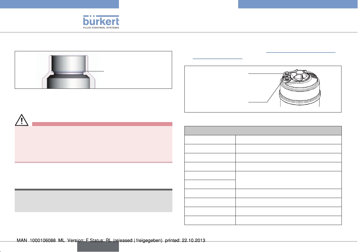
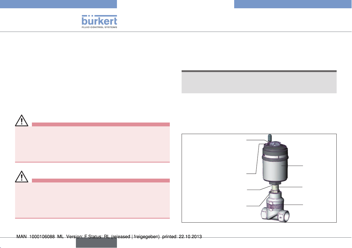
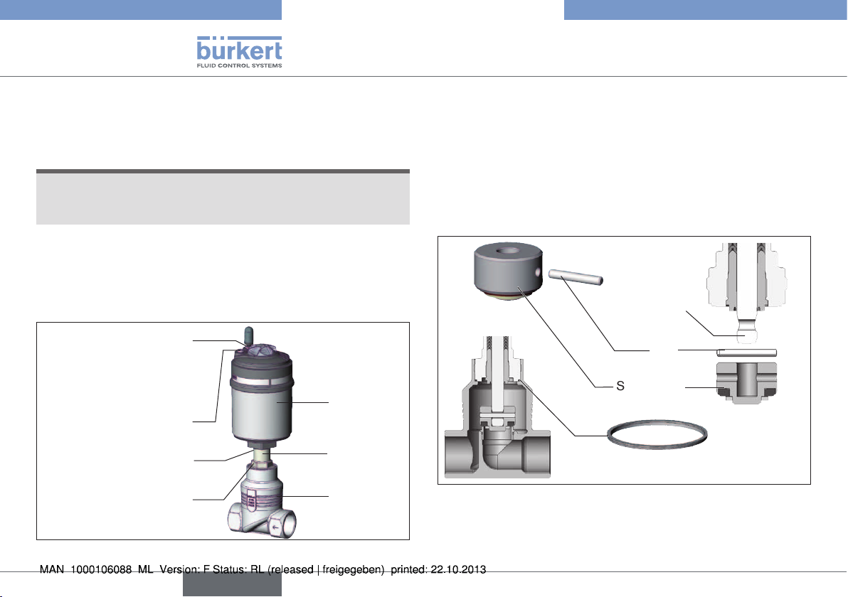
Transparent cap with position indicator
Actuator cover
Actuator body
Globe valve body
Flow direction arrow or
numbers for indicating the
direction of flow
Fig. 1: Globe valve Type 2101, structure and description (1)
The description of the control function (CF) can be found in
chapter entitled “6.2.1 Control functions (CF)”.
Air discharge connection for CFA, CFB
Pilot air port for CFI
Pilot air port for CFA, CFB, CFI
Release bore
Interface actuator/body
with flats
Port connection
Fig. 2: Globe valve Type 2101, Structure and Description (2)
2
1
english
9
Page 10
2(A)
2(B)
2(A)
Type 2101
Structure and function
6.2 Function
Depending on the version, the seat of the valve is closed with or
against the medium flow.
Spring force (CFA) or pneumatic pilot pressure (CFB and CFI) generates the closing force on the swivel plate. The force is transferred
via a spindle which is connected to the actuator piston.
6.2.1 Control functions (CF)
WARNING!
For control function I – Danger if pilot pressure fails!
For control function I control and resetting occur pneumatically. If
the pressure fails, no defined position is reached.
▶ To ensure a controlled restart, first pressurise the device with
pilot pressure, then switch on the medium.
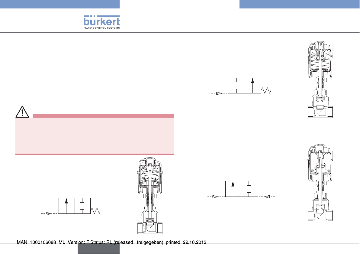
Control function A (CFA)
Normally closed by spring action
1(P)
Control function B (CFB)
Normally open by spring action
1(P)
Control function I (CFI)
Actuating function via reciprocal pressurisation.
1(P)
10
english
Page 11
english
Type 2101
Structure and function
6.2.2 Flow direction below seat
Depending on the version, the valve is closed against the medium
flow with spring force (control function A, CFA) or with pilot
pressure (control function B or I, CFB or CFI).
As the medium pressure is under the swivel plate, this pressure
contributes to the opening of the valve.
WARNING!
Medium may be discharged if minimum pilot pressure is too
low or medium pressure too high!
If the minimum pilot pressure is too low for CFB and CFI or the
permitted medium pressure is exceeded, leaks may occur.
▶ Observe minimum pilot pressure
▶ Do not exceed medium pressure.
▶ See chapter entitled “7.4.1 Temperature ranges”.
CFA CFB /
CFI
6.2.3 Flow direction above seat
The valve is closed by spring force (control function A, CFA) with
the medium flow. As the medium pressure is over the swivel plate, it
supports the closing process of the valve and also contributes to the
sealing of the valve seat. The valve is opened by the pilot pressure.
WARNING!
Risk of injury from water hammer.
A water hammer could crack the lines and device.
Due to the risk of water hammer, valves with a flow direction
above seat must not be used for liquid media.
▶ Consider the type of flow direction and the type of medium for
operation of the device.
To ensure complete opening, the minimum pilot pressure
must be used!
Fig. 3: Flow direction below seat
(Rest open/closed, closing against medium)
Fig. 4: Flow direction above seat (rest closed, closing with
medium)
11
Page 12
Type 2101
Technical data
7 TECHNICAL DATA
7.1 Conformity
Type 2101 conforms with the EC Directives according to the EC
Declaration of Conformity.
7.2 Standards
The applied standards, which verify conformity with the EC Directives, can be found on the EC-Type Examination Certificate and / or
the EC Declaration of Conformity.
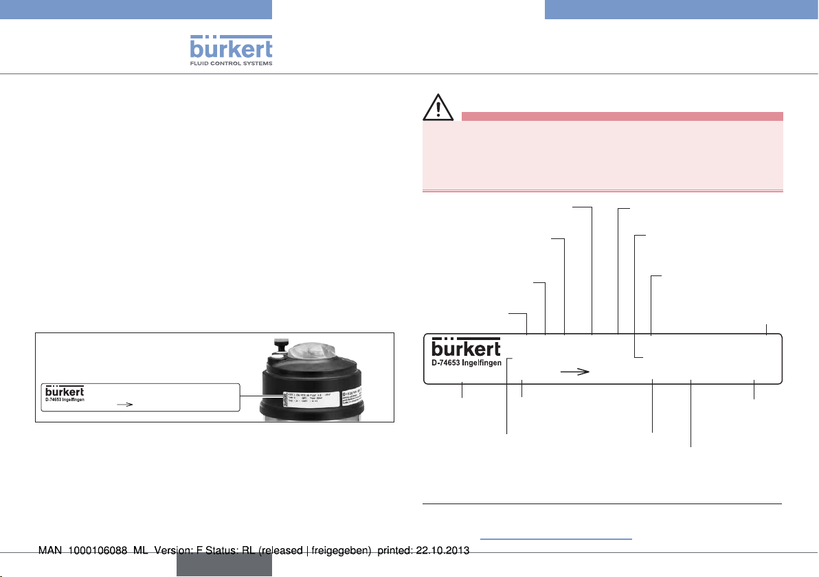
7.3 Type label
Example:
CE
W3ZLT
00189700
2101 A 25M PTFE VA
Tmed -10°C - +180°C
Flow 1 2 DIN
Pilot 4,8-10bar
Pmed 16,0bar
DN25 Kv13,0
Fig. 5: Example of type label
WARNING!
Risk of injury from high pressure!
Important device-specific technical specifications are indicated on
the type label.
▶ Observe permitted pressure range on the type label of the device.
Sealing material
Orifice of the body /
actuator size
Control function
(CF)
Type
00189700
ID number of
the device
Permitted medium
temperature
1)
2101 A 25M PTFE VA
Tmed -10°C - +180°C
Flow 1 2 DIN
Flow direction
Main dimensions
port connection
Body material
Permitted
medium pressure
Pilot 4,8-10bar
Pmed 16,0bar
DN25 Kv13,0
1)
Permitted
pilot pressure
CE identification
W3ZLT
Date of
manufacture
(encoded)
Flow capacity in
standard production
conditions
CE
12
1) For a description of the versions see the following chapter
entitled “7.5 General technical data”.
english
Page 13
Type 2101
Technical data
7.4 Operating conditions
7.4.1 Temperature ranges
Actuator
size
ø 50 mm
ø 70 mm
ø 90 mm
ø 130 mm
Tab. 1: Temperature Ranges
3) Pilot air ports with push-in connector
4) Pilot air ports with threaded bushing
Actuator
material
Medium
(for PTFE seal)
PPS -10 – +185 °C
2) If a pilot valve is used, the max. ambient temperature is
+55 °C.
The globe valve is suitable for steam sterilization.
Environment
0 – +60 °C
0 – +100 °C
7.4.2 Pressure ranges
Actuator size Maximum pilot pressure
ø 50 mm
2)
10 barø 70 mm
ø 90 mm
ø 130 mm 7 bar
3)
4)
Tab. 2: Pressure Ranges
5) For the device version ø 70 / Orifice 50 / MC 13 the
maximum permitted pilot pressure is limited to 7 bar.
5)
english
13
Page 14
Type 2101
Technical data
Medium and pilot pressure for control function A, flow direction
below the seat (standard)
Maximum medium pressure
Orifice
DN
50 70 90 130 50 70 90 130
10/15 25 25
20 16 20
25 9 16
32
40 6 16
50
-
65 5.0 16
100 6
Tab. 3: Medium and pilot pressure for CFA, standard
[bar]
Actuator size ø [mm] Actuator size ø [mm]
-
8.5 16
10 16 5
10
-
Minimum pilot pressure
5.2
-
-
[bar]
-
-
4.8
5
- 5.680
-
Medium and pilot pressure for control function A, flow direction
below the seat reduced pressure spring force (EC04)
Maximum medium pressure
Orifice
DN
50 70 90 130 50 70 90 130
10/15 14 16
20 6 12
25 3 6
32
50
80 5
Tab. 4: Medium and pilot pressure for CFA, reduced pressure
-
spring force (EC04)
[bar]
Actuator size ø [mm] Actuator size ø [mm]
-
-
3.5 9
3.5 10
-
7.5
-
Minimum pilot pressure
[bar]
3.2
2.5
-
-
2.540 2 6 16
-65
- 3.2
-
2.5
14
english
Page 15
Type 2101
Technical data
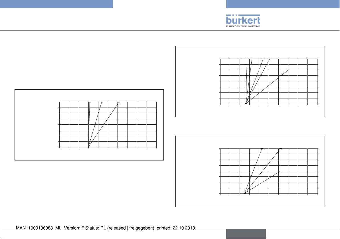
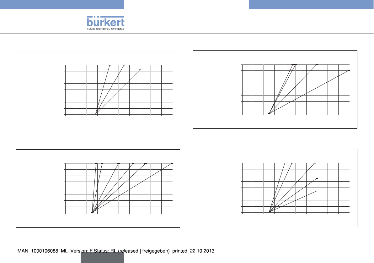
Required minimum pilot pressure depending on medium
pressure
The following graphs illustrate the required minimum pilot pressure
depending on the medium pressure for control functions A, B and I.
Control function A, flow direction above seat
ø 50
CFA above seat
16
14
12
10
8
6
4
2
0
0 1 2 3 4 5 6 7 8 9 10
Medium pressure [bar]
DN15
DN20
DN25
Pilot pressure [bar]
Fig. 6: Pressure graph, actuator ø 50 mm, control function A, flow
direction above seat
ø 70
CFA above seat
16
14
12
10
8
6
4
2
0
0 1 2 3 4 5 6 7 8 9 10
Medium pressure [bar]
DN15
DN20
DN25
DN32
DN40
Pilot pressure [bar]
DN50
Fig. 7: Pressure graph, actuator ø 70 mm, control function A, flow
direction above seat
ø 90
CFA above seat
16
14
12
10
8
6
4
2
0
0 1 2 3 4 5 6 7 8 9 10
Medium pressure [bar]
DN40
DN50
DN65
Pilot pressure [bar]
Fig. 8: Pressure graph, actuator ø 90 mm, control function A, flow
direction above seat
english
15
Page 16
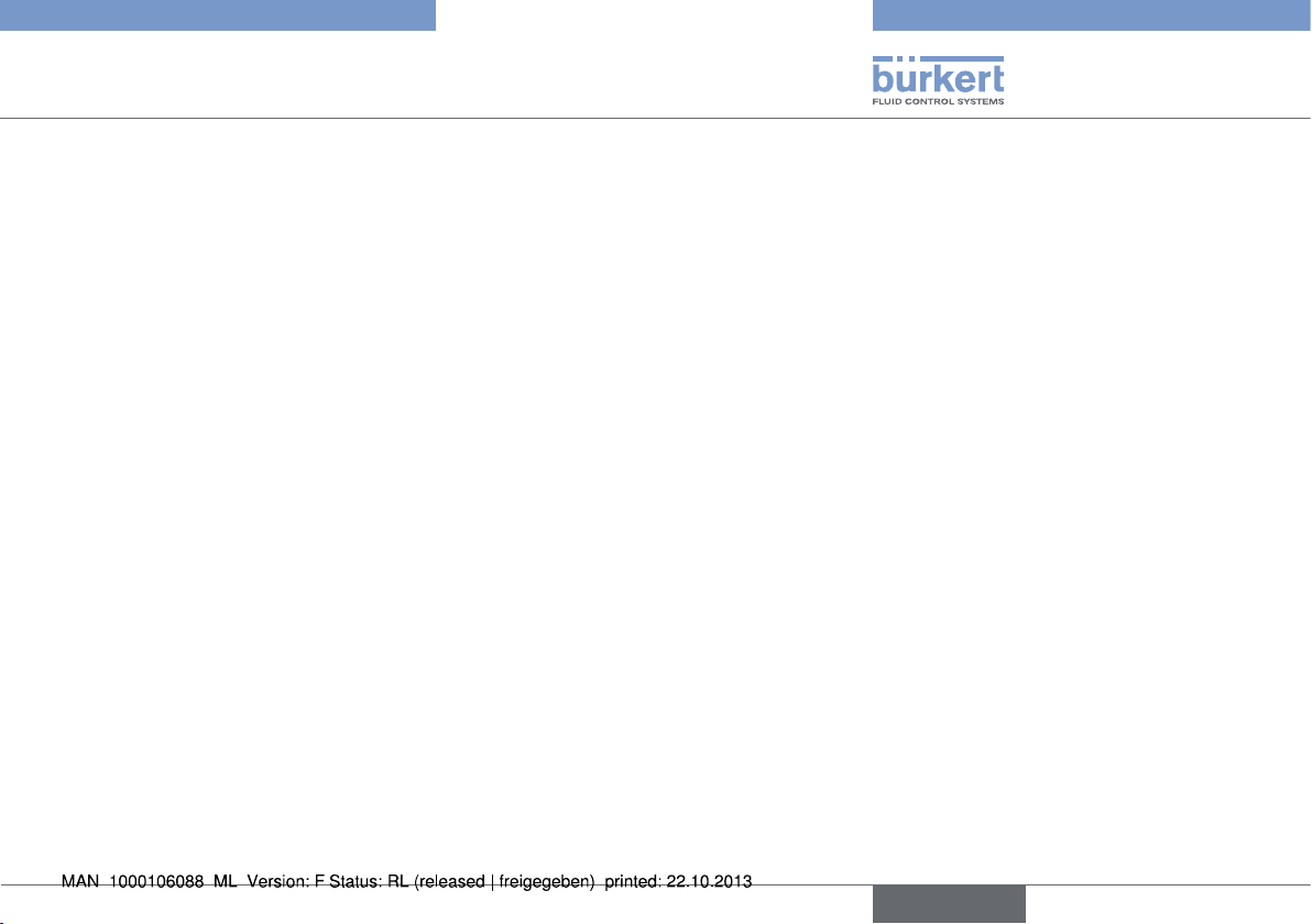
Control functions B and I, flow direction below seat
ø 50 CFB/CFI
below seat
16
14
12
10
8
6
4
2
0
0 1 2 3 4 5 6 7 8 9 10
Medium pressure [bar]
DN15
DN20
DN25
Pilot pressure [bar]
Fig. 9: Pressure graph, actuator ø 50 mm, control functions B and I,
flow direction below seat
Type 2101
Technical data
ø 90 CFB/CFI
below seat
DN32
16
14
12
10
8
6
4
2
0
0 1 2 3 4 5 6 7 8 9 10
Medium pressure [bar]
Pilot pressure [bar]
DN40
DN50
DN65
Fig. 11: Pressure graph, actuator ø 90 mm, control functions B and I,
flow direction below seat
ø 70 CFB/CFI
below seat
DN25
DN32
DN15
16
14
12
10
8
6
4
2
0
0 1 2 3 4 5 6 7 8 9 10
Medium pressure [bar]
DN20
DN40
DN50
Pilot pressure [bar]
Fig. 10: Pressure graph, actuator ø 70 mm, control functions B and I,
flow direction below seat
16
english
ø 130 CFB/CFI
below seat
DN40
16
14
12
10
8
6
4
2
0
0 1 2 3 4 5 6 7 8 9 10
Medium pressure [bar]
DN50
DN65
DN80
DN100
Pilot pressure [bar]
Fig. 12: Pressure graph, actuator ø 130 mm, control functions B and
I, flow direction below seat
Page 17
Type 2101
Technical data
7.5 General technical data
Control functions (CF)
Control function A Normally closed by spring action
Control function B Normally open by spring action
Control function I Actuating function via reciprocal
pressurization
Actuator sizes ø 50 mm
ø 70 mm
ø 90 mm
ø 130 mm
Materials
Body 316L
Actuator PPS and stainless steel
Sealing elements FKM and EPDM
Spindle sealing PTFE V rings with spring compensation
(with silicone grease)
Seat seal PTFE (NBR, EPDM, FKM on request)
Swivel plate
Spindle 1.4401 / 1.4404
Spindle guide
DN10-65 PEEK
DN80-100 1.4401 / 1.4404
Connections
Pilot air port Plug-in connector 6/4 mm or 1/4”
others on request
Medium connection Socket: G ½ – G 4 (NPT, RC on request)
Weld end connection: in accordance with
ISO 4200, DIN 11850 R2
other connections on request
Media
Control medium Neutral gases, air
Flow media Water, alcohol, fuel, hydraulic liquids,
saline solutions, lye, organic solvents
Installation position as required, preferably with actuator in
upright position.
Protection class IP67 in accordance with IEC 529 /
EN 60529
english
17
Page 18
Type 2101
Installation
8 INSTALLATION
8.1 Safety instructions
DANGER!
Risk of injury from high pressure!
▶ Before loosening the lines and valves, turn off the pressure and
vent the lines.
WARNING!
Risk of injury from improper installation!
▶ Installation may be carried out by authorized technicians only
and with the appropriate tools!
Risk of injury from unintentional activation of the system and
an uncontrolled restart!
▶ Secure system from unintentional activation.
▶ Following installation, ensure a controlled restart.
For control function I – Danger if pilot pressure fails!
For control function I control and resetting occur pneumatically. If
the pressure fails, no defined position is reached.
▶ To ensure a controlled restart, first pressurize the device with
pilot pressure, then switch on the medium.
Risk of injury from moving parts in the device!
▶ Do not reach into openings.
8.2 Before installation
• The globe valve can be installed in any installation position, preferably with the actuator face up.
• Before connecting the valve, ensure the lines are flush.
• Observe direction of flow (see type label).
8.2.1 Preparatory work
→ Clean pipelines (sealing material, swarf, etc.).
Devices with welded body
Remove the actuator from the valve body:
→ Clamp the valve body in a holding device.
NOTE!
Damage to the seat seal or the seat contour!
▶ When removing the actuator, ensure that the valve is in open
position.
→ Control function A pressurize the pilot air port 1 with com-
pressed air (5 bar): valve opens.
→ Using a suitable open-end wrench, place the wrench flat on the
tube.
→ Unscrew the actuator from the valve body.
18
english
Page 19

Type 2101
Installation
Air discharge connection
CFA, CFB
Pilot air port
Pilot air port
CFA, CFB, CFI
Release bore
Flats for open-end
wrench
Fig. 13: Installation
Other device versions
2
CFI
1
→ Do not remove actuator unless this is a customer-specific
requirement.
→ Procedure see “Devices with welded body”.
Actuator
Nipple
Valve body
8.3 Installation
WARNING!
Risk of injury from improper assembly!
Assembly with unsuitable tools or non-observance of the tightening torque is dangerous as the device may be damaged.
▶ For installation use an open-end wrench, never a pipe wrench.
▶ Observe the tightening torque (see “Tab. 5: Tightening torques
of valve body / nipples”).
Dirt trap for devices with authorization in accordance with DIN
EN 161
In accordance with DIN EN 161 “Automatic shut-off valves for gas
burners and gas appliances” a dirt trap must be connected upstream
of the valve and prevent the insertion of a 1 mm plug gauge.
→ If the authorisation also applies to stainless steel bodies, the
same type of dirt trap must be attached in front of the globe
valve.
8.3.1 Installation of the valve body
Welded bodies
→ Weld valve body in pipeline system.
Other body versions
→ Connect body to pipeline.
english
19
Page 20
Type 2101
Installation
8.3.2 Install actuator (welded body)
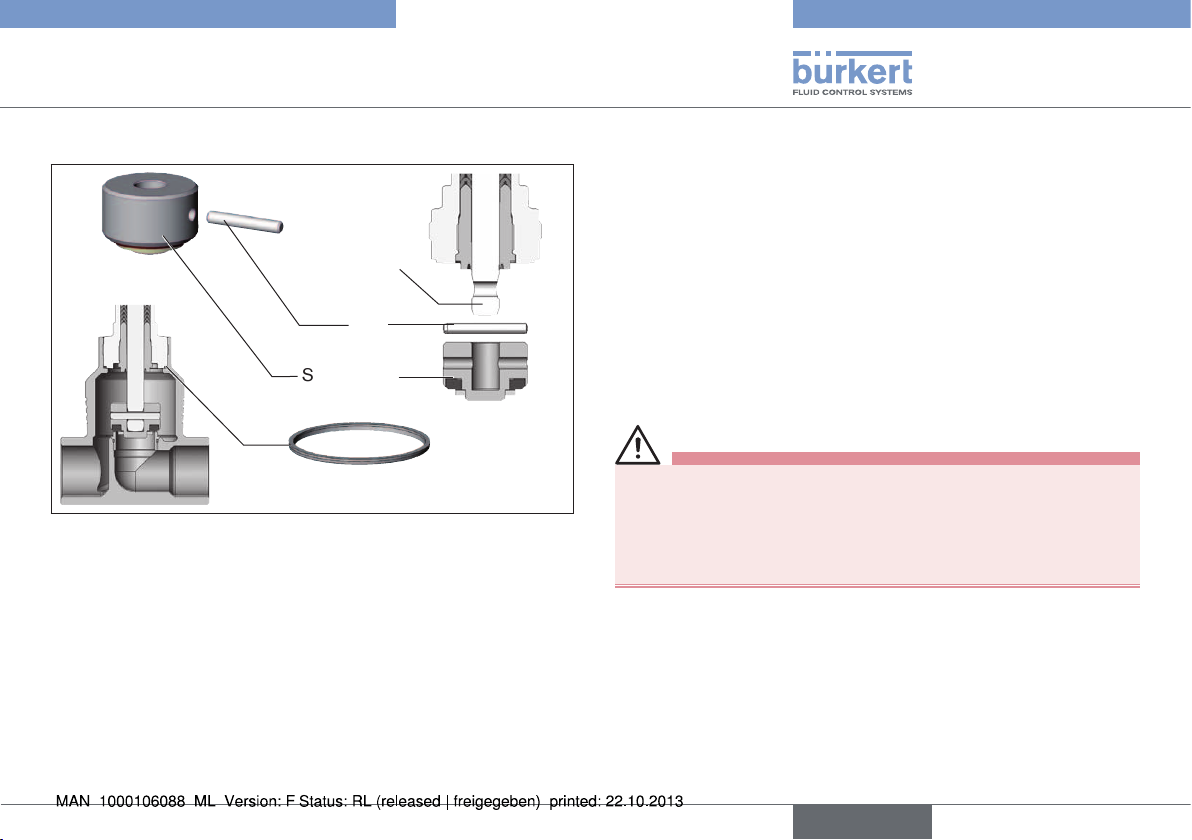
Graphite seal
Fig. 14: Graphite seal
→ Check the graphite seal and if required, replace it.
WARNING!
Danger if incorrect lubricants used!
Unsuitable lubricant may contaminate the medium. In oxygen
applications there is a risk of an explosion!
▶ In specific applications, e.g. oxygen or analysis applications,
use appropriately authorised lubricants only.
→ Grease nipple thread before re-installing the actuator (e.g. with
Klüber paste UH1 96-402 from Klüber).
NOTE!
Damage to the seat seal or the seat contour!
▶ When installing the actuator, ensure that the valve is in open
position.
→ Control function A pressurize the pilot air port 1 with com-
pressed air (5 bar): valve opens.
→ Screw actuator into the valve body.
Observe tightening torque (see “Tab. 5: Tightening torques of
valve body / nipples”).
Air discharge connection
CFA, CFB
Pilot air port
Pilot air port
CFA, CFB, CFI
Fig. 15: Connections
Tightening torques of valve body / nipples
DN Tightening torque [Nm]
13/15 45 ±3
20 50 ±3
25 60 ±3
32
40
50 70 ±3
65 100 ± 3
80 120 ± 5
100 150 ± 5
Tab. 5: Tightening torques of valve body / nipples
2
CFI
1
65 ±3
20
english
Page 21

Type 2101
Installation
8.3.3 Rotating the actuator
The position of the connections can be aligned steplessly by rotating
the actuator through 360°.
NOTE!
Damage to the seat seal or the seat contour!
▶ When rotating the actuator, ensure that the valve is in open
position.
Procedure:
→ Clamp the valve body in a holding device
(applies only to valves which have not yet been installed).
→ Control function A pressurize the pilot air port 1 with com-
pressed air (5 bar): valve opens.
→ Counter on the flats of the nipple with a suitable open-end
wrench.
→ Actuator with hexagon:
Place suitable open-end wrench on the hexagon of the actuator.
→ Actuator without hexagon:
Fit special wrench6) exactly to the underside of the actuator.
6) The special key (identification number 665 702) is available from
your Bürkert sales office.
WARNING!
Risk of injury from discharge of medium and pressure!
If the direction of rotation is wrong, the body interface may
become detached.
▶ Rotate the actuator module in the specified direction only (see
“Fig. 16”)!
→ Actuator with hexagon:
Rotate counter-clockwise (as seen from below) to bring the
actuator module into the required position.
→ Actuator without hexagon:
Rotate clockwise (as seen from below) to bring the actuator
module into the required position.
Open-end wrench
Special key
with hexagon
Fig. 16: Rotating with special key / open-end wrench
without hexagon
english
21
Page 22

Type 2101
Installation
8.4 Pneumatic connection
DANGER!
Danger – high pressure in the equipment!
▶ Before loosening the lines and valves, turn off the pressure and
vent the lines.
WARNING!
Risk of injury from unsuitable connection hoses!
Hoses which cannot withstand the pressure and temperature
range may result in hazardous situations.
▶ Use only hoses which are authorised for the indicated pressure
and temperature range.
▶ Observe the data sheet specifications from the hose
manufacturers.
For control function I – Danger if pilot pressure fails!
For control function I control and resetting occur pneumatically. If
the pressure fails, no defined position is reached.
▶ To ensure a controlled restart, first pressurize the device with
pilot pressure, then switch on the medium.
8.4.1 Connection of the control medium
If the position of the pilot air ports for installation of the
hoses is unfavorable, these can be aligned steplessly by
rotating the actuator through 360°.
The procedure is described in the chapter entitled “8.3.3
Rotating the actuator”.
Air discharge connection
CFA, CFB
Pilot air port CFI
Pilot air port
CFA, CFB, CFI
Fig. 17: Pneumatic connection
Control functions A and B:
2
1
→ Connect the control medium to the pilot air port 1 of the actuator
(see “Fig. 17”).
Silencer
For the versions with a plug-in connection the silencer for reducing
the exhaust air noise is supplied loose.
→ Plug the silencer into the free air discharge connection 2
(see “Fig. 17”).
If used in an aggressive environment, we recommend
conveying all free pneumatic connections into a neutral
atmosphere with the aid of a pneumatic hose.
22
english
Page 23

Type 2101
Installation
Control function I:
→ Connect the control medium to the pilot air port 1 and 2 of the
actuator (see “Fig. 18: Pneumatic connection”)
Pressure on connection 1 opens the valve.
Pressure on connection 2 closes the valve.
Air discharge connection
CFA, CFB
Pilot air port CFI
Pilot air port
CFA, CFB, CFI
Fig. 18: Pneumatic connection
Control air hose:
6/4 mm or 1/4” control air hoses can be used.
Optionally a pilot air port is possible via a G 1/8 thread.
2
1
8.5 Removal
DANGER!
Risk of injury from discharge of medium and pressure!
It is dangerous to remove a device which is under pressure due to
the sudden release of pressure or discharge of medium.
▶ Before removing a device, switch off the pressure and vent the
lines.
Procedure:
→ Loosen the pneumatic connection.
→ Remove the device.
english
23
Page 24

Type 2101
Electrical control unit
9 ELECTRICAL CONTROL UNIT
The valve Type 2101 can be combined with following control units:
• Type 8690 Pneumatic Control Unit
• Type 8691 Control head (actuator size ∅ 70 - ∅ 130)
• Type 8695 Control head (actuator size ∅ 50)
• Type 8645 Automation system FreeLINE
• Type 6012 Pilot valve
• Type 6014 P Pilot valve
The electrical connection of the pilot valve or the control
unit is described in the respective operating instructions for
the pilot valve/control unit.
10 MAINTENANCE, CLEANING
10.1 Safety instructions
DANGER!
Danger – high pressure in the equipment!
▶ Before loosening the lines and valves, turn off the pressure and
vent the lines.
Risk of injury due to electrical shock!
▶ Before reaching into the system, switch off the power supply
and secure to prevent reactivation!
▶ Observe applicable accident prevention and safety regulations
for electrical equipment!
WARNING!
Risk of injury from improper maintenance!
▶ Maintenance may be performed by authorised technicians only!
▶ To screw on or unscrew valve body or actuator, use an open-end
wrench, never a pipe wrench, and observe tightening torques.
Risk of injury from unintentional activation of the system and
an uncontrolled restart!
▶ Secure system from unintentional activation.
▶ Following maintenance, ensure a controlled restart.
24
english
Page 25

Type 2101
Maintenance, Cleaning
WARNING!
For control function I – Danger if pilot pressure fails!
For control function I control and resetting occur pneumatically.
If the pressure fails, no defined position is reached.
▶ To ensure a controlled restart, first pressurize the device with
pilot pressure, then switch on the medium.
Risk of injury from moving parts in the device!
▶ Do not reach into openings.
10.2 Maintenance work
Actuator:
The actuator of the globe valve is maintenance-free provided it is
used according to these operating instructions.
Wearing parts of the globe valve:
Parts which are subject to natural wear:
• Seals
• Swivel plate
→ If leaks occur, replace the particular wearing part with an appro-
priate spare part.
(For spare-part sets and installation tools see chapter entitled
“12 Replacement parts”).
Visual inspection:
Perform regular visual inspections according to the application
conditions:
→ Check media connections for leaks.
→ Check release bore on the tube for leaks.
Release bore
Fig. 19: Release bore
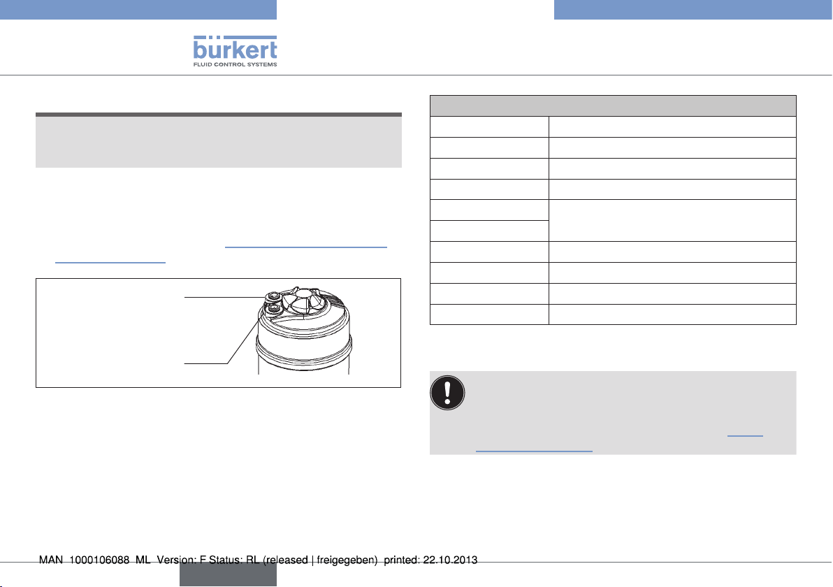
10.2.1 Cleaning
Commercially available cleaning agents can be used to clean the
outside.
NOTE!
Avoid causing damage with cleaning agents.
▶ Before cleaning, check that the cleaning agents are compatible
with the body materials and seals.
The replacing of the wearing parts is described in chapter
“10.3 Replacing the wearing parts”.
english
25
Page 26
Type 2101
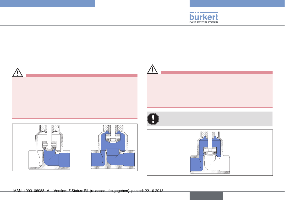
Maintenance, Cleaning
10.3 Replacing the wearing parts
10.3.1 Replacing the valve set
The valve set consists of
• Swivel plate
• Pin
• Graphite seal
Before the valve set can be replaced, the actuator must be removed
from the valve body.
DANGER!
Risk of injury from discharge of medium and pressure!
It is dangerous to remove a device which is under pressure due to
the sudden release of pressure or discharge of medium.
▶ Before removing a device, switch off the pressure and vent the
lines.
WARNING!
Risk of injury if the wrong tools are used!
It is dangerous to use unsuitable tools for installation work as the
device may be damaged.
▶ To remove the actuator from the valve body, use an open-end
wrench, never a pipe wrench.
Remove the actuator from the valve body:
→ Clamp the valve body in a holding device
(applies only to valves which have not yet been installed).
NOTE!
Damage to the seat seal or the seat contour!
▶ When removing the actuator, ensure that the valve is in open
position.
→ Control function A pressurize the pilot air port 1 with com-
pressed air (5 bar): valve opens.
→ Using a suitable open-end wrench, place the wrench flat on the
tube.
→ Unscrew the actuator from the valve body.
CFI
2
1
Actuator
Nipple
Valve body
Air discharge connection
CFA, CFB
Pilot air port
Pilot air port
CFA, CFB, CFI
Release bore
Flats for open-end
wrench
26
Fig. 20: Designation parts
english
Page 27
Type 2101
Maintenance, Cleaning
Replacing valve set
Spindle
Pin
Swivel plate
Graphite seal
Fig. 21: Valve set
Procedure:
→ Support swivel plate on the cylindrical part with the aid of a
prism or something similar.
→ Knock out pin with a suitable pin punch.
Pin punch ø 3 mm, for spindle diameter 10 mm on the swivel
plate.
Pin punch ø 5 mm, for spindle diameter 14 mm on the swivel
plate.
→ Remove swivel plate.
→ Connect new swivel plate to the spindle.
→ Align bores of the swivel plate and spindle.
→ Support swivel plate on the cylindrical part with the aid of a
prism or something similar.
→ Insert pin into the bore.
→ Swage pin bores on both sides of the swivel plate using a chisel
or center punch.
Installing the actuator on the valve body
→ Check the graphite seal and if required, replace it.
WARNING!
Danger if incorrect lubricants used!
Unsuitable lubricant may contaminate the medium. In oxygen
applications there is a risk of an explosion!
▶ In specific applications, e.g. oxygen or analysis applications, use
appropriately authorised lubricants only.
→ Grease nipple thread before re-installing the actuator (e.g. with
Klüber paste UH1 96-402 from Klüber).
english
27
Page 28
Type 2101
Maintenance, Cleaning
NOTE!
Damage to the seat seal or the seat contour!
▶ When installing the actuator, ensure that the valve is in open
position.
→ Control function A pressurize the pilot air port 1 with com-
pressed air (5 bar): valve opens.
→ Screw actuator into the valve body.
Observe tightening torque (see “Tab. 6: Tightening torques of
valve body / nipples”).
Air discharge connection
CFA, CFB
Pilot air port
Pilot air port
CFA, CFB, CFI
Fig. 22: Connections
2
CFI
1
Tightening torques of valve body / nipples
Orifice Tightening torque [Nm]
13/15 45 ±3
20 50 ±3
25 60 ±3
32
40
50 70 ±3
65 100 ±3
80 120 ±5
100 150 ±5
Tab. 6: Tightening torques of valve body / nipples
If the position of the pilot air ports for installation of the
hoses is unfavorable, these can be aligned steplessly by
rotating the actuator through 360°.
The procedure is described in the chapter entitled “8.3.3
Rotating the actuator”.
65 ±3
28
english
Page 29
Type 2101
Maintenance, Cleaning
10.3.2 Replacing the packing gland
The packing gland cannot be replaced for the device
combination ø 70 / orifice 50.
The seal set for the packing gland contains
SP10 / SP14
• 1 support ring
• 7 chevron seals
• 2 pressure rings
• 1 pressure spring
• 1 spindle guide
• 1 graphite seal
• Lubricant
SP22
• 1 support ring
• 7 chevron seals
• 2 pressure rings
• 1 pressure spring
• 1 spacer
• 1 graphite seal
• Lubricant
Fig. 23: Seal set for packing gland
DANGER!
Risk of injury from discharge of medium and pressure!
It is dangerous to remove a device which is under pressure due to
the sudden release of pressure or discharge of medium.
▶ Before removing a device, switch off the pressure and vent the
lines.
WARNING!
Risk of injury if the wrong tools are used!
It is dangerous to use unsuitable tools for installation work as the
device may be damaged.
▶ To remove the actuator from the valve body, use an open-end
wrench, never a pipe wrench.
▶ To replace the packing gland, use a special installation wrench,
modified socket wrench or a socket wrench.
▶ Observe tightening torques.
Before the packing gland can be replaced, the actuator must be
removed from the valve body and the swivel plate removed.
english
29
Page 30
Type 2101
Maintenance, Cleaning
Remove the actuator from the valve body:
→ Clamp the valve body in a holding device
(applies only to valves which have not yet been installed).
NOTE!
Damage to the seat seal or the seat contour!
▶ When removing the actuator, ensure that the valve is in open
position.
→ Control function A pressurize the pilot air port 1 with com-
pressed air (5 bar): valve opens.
→ Using a suitable open-end wrench, place the wrench flat on the
tube.
→ Unscrew the actuator from the valve body.
CFI
2
1
Actuator
Nipple
Valve body
Air discharge connection
CFA, CFB
Pilot air port
Pilot air port
CFA, CFB, CFI
Release bore
Flats for open-end
wrench
Removing the swivel plate
→ Knock out the pin with a suitable pin punch.
Pin punch ø 3 mm, for spindle diameter 10 mm on the swivel
plate.
Pin punch ø 5 mm, for spindle diameter 14 mm on the swivel
plate.
→ Remove swivel plate.
Spindle
Pin
Swivel plate
Graphite seal
Fig. 25: Valve set
Fig. 24: Designation parts
30
english
Page 31

Maintenance, Cleaning
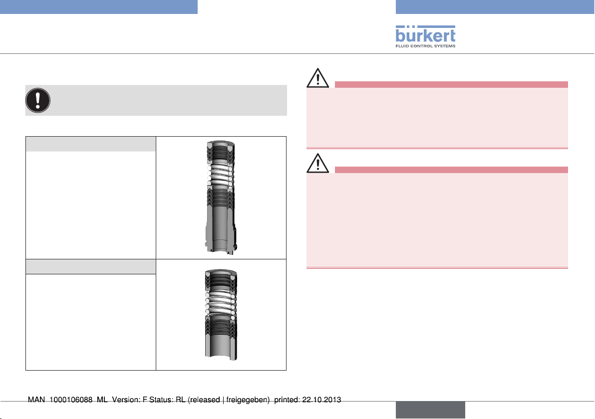
Replacing packing gland
Type 2101
Packing gland tube
Packing gland tube
Packing gland
Spindle guide
Spindle
Series production status
up to January 2013
Fig. 26: Replacing packing gland (series production status up to
January 2013)
Series production status since January 2013
SP10 / SP14
Fig. 27: Replacing packing gland SP10 / SP14 (series production
status since January 2013)
Installation wrench
Packing gland tube
Packing gland
Spindle guide
Spindle
Packing gland
Spacer
Spindle
VA spindle guide
SP22
Fig. 28: Replacing packing gland SP22
Series production status up to January 2013:
→ Unscrew the spindle guide with the aid of the installation
wrench7) and an open-end wrench.
Series production status since January 2013 SP10 / SP14:
→ Unscrew the spindle guide with the aid of a modified socket
wrench7).
SP22:
→ Unscrew the VA spindle guide with the aid of an open-end wrench.
7) The installation wrench or modified socket wrench is available
from your Bürkert sales office.
english
31
Page 32

Type 2101
Maintenance, Cleaning
WARNING!
Risk of injury from parts jumping out!
When the spindle opening is exposed, the individual parts of the
packing gland are pressed out at an undefined speed when the
pilot air ports is pressurized.
▶ Before pressurizing with control air, safeguard the ambient area
of the discharge opening (e.g. place spindle on a firm base).
→ Control function A and I Pressurize pilot air port 1 with 6 – 8
bar (see “Fig. 24: Designation parts”).
→ Control function B Pressurize pilot air port 2 with 6 – 8 bar (see
“Fig. 24: Designation parts”).
→ Grease the individual parts of the new packing gland with the
upplied lubricant.
→ Connect the individual parts to the spindle in the specified
direction and sequence (as illustrated in “Fig. 29: Seal set for
packing gland”).
→ Push packing gland into the packing gland tube.
→ Screw spindle guide / VA spindle guide back in using the socket
wrench / open-end wrench. Observe torque (see “Tab. 7: Tightening torques of spindle”).
Support ring
Upper chevron seals
Upper pressure ring
Pressure spring
Lower pressure ring
Lower chevron seals
Insertion direction
for packing gland parts
SP10 / SP14
Fig. 29: Seal set for packing gland
Tightening torques of spindle
Spindle diameter Tightening torque [Nm]
10 mm 6
14 mm 15
22 mm 60
Tab. 7: Tightening torques of spindle
Spacer
Spindle guide
VA spindle guide
8)
SP22
32
8) Is not included in the seal set
english
Page 33

Type 2101
Maintenance, Cleaning
Installing swivel plate
→ Connect swivel plate to the spindle.
→ Align bores of the swivel plate and spindle.
→ Support swivel plate on the cylindrical part with the aid of a
prism or something similar.
→ Insert pin into the bore.
→ Swage pin bores on both sides of the swivel plate using a chisel
or center punch.
Spindle
Pin
Swivel plate
Fig. 30: Swivel plate
Installing the actuator on the valve body
For description see chapter entitled “Installing the actuator on the
valve body”, page 27.
11 MALFUNCTIONS
Malfunction Remedial action
Actuator does
not switch
Pilot air port interchanged
CFA: → Connecting pilot air port 1
CFB:
CFI:
Pilot pressure too low
→ Connecting pilot air port 1
→ Pilot air port 1: Open
Pilot air port 2: Close
→ Observe pressure specifications on the
type label
Medium pressure too high
→ Observe pressure specifications on the
type label
Flow direction reversed
→ Observe direction arrow on the body
9)
english
33
Page 34

Type 2101
Replacement parts
Malfunction Remedial action
Valve is not
sealed
Dirt between seal and valve seat
→ Installing dirt trap
Seat seal worn
→ Installing new swivel plate
Flow direction reversed
→ Observe direction arrow on the body
Medium pressure too high
→ Observe pressure specifications on the
type label
Pilot pressure too low
→ Observe pressure specifications on the
type label
Valve is leaking on
the release bore
Tab. 8: Malfunctions
9) See “8.4 Pneumatic connection”.
Packing gland worn
→ Renew packing gland or replace actuator
12 REPLACEMENT PARTS
WARNING!
Risk of injury when opening the actuator!
The actuator contains a tensioned spring. If the actuator is
opened, there is a risk of injury from the spring jumping out!
▶ The actuator must not be opened.
CAUTION!
Risk of injury and/or damage by the use of incorrect parts!
Incorrect accessories and unsuitable replacement parts may
cause injuries and damage the device and the surrounding area.
▶ Use only original accessories and original replacement parts
from Bürkert.
12.1 Replacement part sets
The following replacement part sets are available for the globe valve
Type 2101:
• Valve set
consists of swivel plate with seal, pin and graphite seal.
• Sealing set for packing gland
consists of the individual parts of the packing gland, graphite seal
and lubricant
(the (modified) socket wrench is not included in the sealing set).
34
english
Page 35

Type 2101
Replacement parts
Valve set with PTFE seal
Orifice Order no.
15 011 134
20 011 171
25 160 737
32 011 208
40 011 209
50 216 431
65 241 777
80 155 492
100 155 493
Tab. 9: Valve set with PTFE seal
Sealing set for packing gland
Spindle ∅ Orifice
10 15 – 40
14 32 – 65
22 80 – 100 ∅ 130 252 545
Tab. 10: Sealing set for packing gland
Actuator
size
∅ 50
∅ 70
∅ 90
∅ 130
Order no.
216 433
216 435
VA spindle guide for packing gland
Spindle ∅ Orifice
22 80 – 100 ∅ 130 252 543
Tab. 11: VA spindle guide for packing gland
1 Graphite seal
2 Swivel plate
3 Pin
4 Sealing set for
packing gland
SP10 / SP14
5 Sealing set for
packing gland SP22
6 VA spindle guide
SP22
1
2
Fig. 31: Replacement parts
Sealing set
3
Actuator
size
Order no.
4
5
6
english
35
Page 36

Type 2101
Packaging, Transport, Storage
12.2 Installation tools
Installation wrench for packing gland
(Only for removal of packing glands up to January 2013)
Installation wrench Orifice Order no.
Spindle ∅ 10 mm 15 – 40 665 700
Spindle ∅ 14 mm 32 – 65 665 701
Tab. 12: Installation wrench
Modified socket wrench for packing gland
(Series production status since January 2013)
AF
Socket wrench Orifice AF Order no.
Spindle ∅
10 mm
Spindle ∅
14 mm
Tab. 13: Modified socket wrench
Special wrench for rotating the actuator
Order no.
Tab. 14: Special wrench
If you have any queries, please contact your Bürkert sales
office.
15 – 40 19 683 221
32 – 65 21 683 223
665 702
13 PACKAGING, TRANSPORT,
STORAGE
NOTE!
Transport damages!
Inadequately protected equipment may be damaged during transport.
• During transportation protect the device against wet and dirt in
shock-resistant packaging.
• Avoid exceeding or dropping below the permitted storage
temperature.
Incorrect storage may damage the device.
• Store the device in a dry and dust-free location!
• Storage temperature -20 – +65 °C.
Damage to the environment caused by device components
contaminated with media.
▶ Dispose of the device and packaging in an environmentally
friendly manner.
▶ Observe applicable regulations on disposal and the environment.
Note:
Observe national waste disposal regulations.
36
english
Page 37

Typ 2101
Geradsitzventil Typ 2101
1 DIE BEDIENUNGSANLEITUNG .........................................................38
1.1 Darstellungsmittel ....................................................................38
1.2 Begriffsdefinition / Abkürzung ..............................................38
2 BESTIMMUNGSGEMÄSSE VERWENDUNG................................39
2.1 Beschränkungen ......................................................................39
3 GRUNDLEGENDE SICHERHEITSHINWEISE .............................. 39
4 ALLGEMEINE HINWEISE ....................................................................... 41
4.1 Kontaktadresse ........................................................................41
4.2 Gewährleistung ........................................................................41
4.3 Informationen im Internet .......................................................41
5 PRODUKTBESCHREIBUNG ................................................................ 41
5.1 Allgemeine Beschreibung .....................................................41
5.2 Ausführungen ...........................................................................41
5.3 Eigenschaften...........................................................................42
5.4 Vorgesehener Einsatzbereich ...............................................42
6 AUFBAU UND FUNKTION .................................................................... 43
6.1 Aufbau ........................................................................................43
6.2 Funktion .....................................................................................44
7 TECHNISCHE DATEN ............................................................................. 46
7.1 Konformität ................................................................................46
7.2 Normen ......................................................................................46
7.3 Typschild ....................................................................................46
7.4 Betriebsbedingungen .............................................................47
7.5 Allgemeine Technische Daten ..............................................51
8 MONTAGE .....................................................................................................52
8.1 Sicherheitshinweise ................................................................52
8.2 Vor dem Einbau........................................................................52
8.3 Einbau ........................................................................................53
8.4 Pneumatischer Anschluss .....................................................56
8.5 Demontage ...............................................................................57
9 ELEKTRISCHE ANSTEUERUNG ........................................................58
10 WARTUNG, REINIGUNG ........................................................................ 58
10.1 Sicherheitshinweise ................................................................58
10.2 Wartungsarbeiten ....................................................................59
10.3 Austausch Verschleißteile .....................................................60
11 STÖRUNGEN ............................................................................................... 67
12 ERSATZTEILE .............................................................................................. 68
12.1 Ersatzteilsätze...........................................................................68
12.2 Montagewerkzeuge .................................................................70
13 TRANSPORT, LAGERUNG, VERPACKUNG ..................................70
deutsch
37
Page 38

Typ 2101
Die Bedienungsanleitung
1 DIE BEDIENUNGSANLEITUNG
Die Bedienungsanleitung beschreibt den gesamten Lebenszyklus
des Geräts. Bewahren Sie diese Anleitung so auf, dass sie für jeden
Benutzer gut zugänglich ist und jedem neuen Eigentümer des Geräts
wieder zur Verfügung steht.
WARNUNG!
Die Bedienungsanleitung enthält wichtige Informationen zur
Sicherheit!
Das Nichtbeachten dieser Hinweise kann zu gefährlichen Situationen führen.
▶ Die Bedienungsanleitung muss gelesen und verstanden werden.
1.1 Darstellungsmittel
GEFAHR!
Warnt vor einer unmittelbaren Gefahr!
▶ Bei Nichtbeachtung sind Tod oder schwere Verletzungen die
Folge.
WARNUNG!
Warnt vor einer möglicherweise gefährlichen Situation!
▶ Bei Nichtbeachtung drohen schwere Verletzungen oder Tod.
VORSICHT!
Warnt vor einer möglichen Gefährdung!
▶ Nichtbeachtung kann mittelschwere oder leichte Verletzungen
zur Folge haben.
HINWEIS!
Warnt vor Sachschäden!
▶ Bei Nichtbeachtung kann das Gerät oder die Anlage beschädigt
werden.
bezeichnet wichtige Zusatzinformationen, Tipps und
Empfehlungen.
verweist auf Informationen in dieser Bedienungsanleitung
oder in anderen Dokumentationen.
→ markiert einen Arbeitsschritt, den Sie ausführen müssen.
1.2 Begriffsdefinition / Abkürzung
Der in dieser Anleitung verwendeten Begriff „Gerät“ steht immer für
das Geradsitzventil Typ 2101.
Die in dieser Anleitung verwendete Abkürzung „Ex“ steht immer für
„explosionsgeschützt“.
38
deutsch
Page 39

Typ 2101
Bestimmungsgemäße Verwendung
2 BESTIMMUNGSGEMÄSSE
VERWENDUNG
Bei nicht bestimmungsgemäßem Einsatz des Geradsitzventils
Typ 2101 können Gefahren für Personen, Anlagen in der
Umgebung und die Umwelt entstehen.
▶ Das Gerät ist für die Steuerung des Durchflusses von flüssigen
und gasförmigen Medien konzipiert.
▶ Für den Einsatz sind die in den Vertragsdokumenten, der Bedie-
nungsanleitung und auf dem Typschild spezifizierten zulässigen
Daten, Betriebs- und Einsatzbedingungen zu beachten. Die
vorgesehenen Einsatzfälle sind im Kapitel „5 Produktbeschreibung“ aufgeführt.
▶ Das Gerät nur in Verbindung mit von Bürkert empfohlenen bzw.
zugelassenen Fremdgeräten und -komponenten einsetzen.
▶ Voraussetzungen für den sicheren und einwandfreien Betrieb
sind sachgemäßer Transport, sachgemäße Lagerung und Installation sowie sorgfältige Bedienung und Instandhaltung.
▶ Setzen Sie das Gerät nur bestimmungsgemäß ein.
2.1 Beschränkungen
Beachten Sie bei der Ausfuhr des Systems/Geräts gegebenenfalls
bestehende Beschränkungen.
3 GRUNDLEGENDE
SICHERHEITSHINWEISE
Diese Sicherheitshinweise berücksichtigen keine
• Zufälligkeiten und Ereignisse, die bei Montage, Betrieb und Wartung
der Geräte auftreten können.
• ortsbezogenen Sicherheitsbestimmungen, für deren Einhaltung, auch
in Bezug auf das Montagepersonal, der Betreiber verantwortlich ist.
GEFAHR!
Gefahr durch hohen Druck!
▶ Vor dem Lösen von Leitungen und Ventilen den Druck abschal-
ten und Leitungen entlüften.
Gefahr durch elektrische Spannung!
▶ Vor Eingriffen in das Gerät die Spannung abschalten und vor
Wiedereinschalten sichern!
▶ Die geltenden Unfallverhütungs- und Sicherheitsbestimmungen
für elektrische Geräte beachten!
WARNUNG!
Verletzungsgefahr beim Öffnen des Antriebs!
Der Antrieb enthält eine gespannte Feder. Beim Öffnen des Antriebs
kann es durch die herausspringende Feder zu Verletzungen kommen!
▶ Der Antrieb darf nicht geöffnet werden.
Verletzungsgefahr durch sich bewegende Teile im Gerät!
▶ Nicht in Öffnungen fassen.
deutsch
39
Page 40

Typ 2101
Grundlegende Sicherheitshinweise
VORSICHT!
Verbrennungsgefahr!
Bei Dauerbetrieb kann die Geräteoberfläche heiß werden.
▶ Das Gerät nicht mit bloßen Händen berühren.
Allgemeine Gefahrensituationen.
Zum Schutz vor Verletzungen ist zu beachten:
▶ Dass die Anlage nicht unbeabsichtigt betätigt werden kann.
▶ Installations- und Instandhaltungsarbeiten dürfen nur von auto-
risiertem Fachpersonal mit geeignetem Werkzeug ausgeführt
werden.
▶ Nach einer Unterbrechung der elektrischen oder pneumatischen
Versorgung ist ein definierter oder kontrollierter Wiederanlauf des
Prozesses zu gewährleisten.
▶ Das Gerät darf nur in einwandfreiem Zustand und unter Beachtung
der Bedienungsanleitung betrieben werden.
▶ Für die Einsatzplanung und den Betrieb des Geräts müssen die
allgemeinen Regeln der Technik eingehalten werden.
▶ Im explosionsgefährdeten Bereich darf das Geradsitzventil Typ
2101 nur entsprechend der Spezifikation auf dem separaten ExTypschild eingesetzt werden. Für den Einsatz muss die dem Gerät
beiliegende Zusatzinformation mit Sicherheitshinweisen für den
Ex-Bereich beachtet werden.
▶ Geräte ohne separates Ex-Typschild dürfen nicht im explosions-
gefährdeten Bereich eingesetzt werden.
Zum Schutz vor Sachschäden am Gerät ist zu beachten:
• In die Medienanschlüsse nur Medien einspeisen, die im Kapitel „7
Technische Daten“ aufgeführt sind.
• Ventil nicht mechanisch belasten (z. B. durch Ablage von Gegenständen oder als Trittstufe).
• Keine äußerlichen Veränderungen an den Ventilen vornehmen.
Gehäuseteile und Schrauben nicht lackieren.
Das Geradsitzventil Typ 2101 wurde unter Einbeziehung der
anerkannten sicherheitstechnischen Regeln entwickelt und
entspricht dem Stand der Technik. Trotzdem können Gefahren
entstehen.
40
deutsch
Page 41

Typ 2101
Allgemeine Hinweise
4 ALLGEMEINE HINWEISE
4.1 Kontaktadresse
Deutschland
Bürkert Fluid Control System
Sales Center
Chr.-Bürkert-Str. 13-17
D-74653 Ingelfingen
Tel. + 49 (0) 7940 - 10 91 111
Fax + 49 (0) 7940 - 10 91 448
E-mail: info@de.buerkert.com
International
Die Kontaktadressen finden Sie auf den letzten Seiten der
gedruckten Bedienungsanleitung.
Außerdem im Internet unter: www.burkert.com
4.2 Gewährleistung
Voraussetzung für die Gewährleistung ist der bestimmungsgemäße Gebrauch des Geräts unter Beachtung der spezifizierten
Einsatzbedingungen.
4.3 Informationen im Internet
Bedienungsanleitungen und Datenblätter zum Typ 2101 finden Sie im
Internet unter: www.buerkert.de
5 PRODUKTBESCHREIBUNG
5.1 Allgemeine Beschreibung
Das 2/2-Wege-Geradsitzventil Typ 2101 ist geeignet für flüssige
und gasförmige Medien. Es steuert mittels neutraler Gase oder Luft
(Steuermedien) den Durchfluss von Wasser, Alkohol, Öl, Treibstoff,
Hydraulikflüssigkeit, Salzlösung, Lauge, organischem Lösungsmittel
und Dampf (Durchflussmedien).
Ein besonderes Merkmal der Geradsitzventile sind eingeschraubte
Sitze, die insbesondere beim Regelventil (Typ 2301) zur Reduzierung
der Nennweite eingesetzt werden können.
Definition DN
DN bezeichnet die Nennweite des Sitzes, nicht die Nennweite des Leitungsanschlusses.
5.2 Ausführungen
Das Geradsitzventil Typ 2101 gibt es in 2 Ausführungen:
• Standardausführung – ohne separates Ex-Typschild.
Die Standardausführung darf nicht im explosionsgefährdeten
Bereich eingesetzt werden.
• Ex-Ausführung – mit separatem Ex-Typschild.
Die Ex-Ausführung darf im explosionsgefährdeten Bereich
eingesetzt werden. Dabei müssen die Spezifikationen auf dem
separaten Ex-Typschild und die dem Gerät beiliegende Zusatzinformation mit Sicherheitshinweisen für den Ex-Bereich beachtet
werden.
deutsch
41
Page 42

Typ 2101
Produktbeschreibung
5.3 Eigenschaften
• Hohe Dichtheit durch selbstnachstellende Stopfbuchsen
(Spindeldichtelement).
• Hohe Sitzdichtheit durch Pendelteller.
• Antrieb um 360° stufenlos drehbar.
• Unter normalen Bedingungen wartungsfrei.
5.3.1 Optionen
• Ansteuerung
Je nach Anforderung stehen Ansteuerungen verschiedener Ausführungen zu Verfügung.
• Hubbegrenzung
Begrenzung der maximalen Offenstellung / Durchflussmenge
mittels Einstellschraube.
• Rückmelder
Das Gerät gibt es mit mechanischen Endschaltern oder induktiven
Näherungsschaltern.
5.3.2 Gerätevarianten
Das Geradsitzventil ist für folgende Antriebsgrößen lieferbar:
ø 50 mm, ø 70 mm, ø 90 mm, ø 130 mm.
5.3.3 Einschränkungen
WARNUNG!
Verletzungsgefahr durch Schließschlag!
Ein Schließschlag könnte zum Bersten von Leitungen und Gerät
führen.
Wegen Schließschlaggefahr dürfen Ventile mit Anströmung
über Sitz nicht für flüssige Medien eingesetzt werden.
▶ Für den Betrieb des Geräts die Art der Anströmung und die Art
des Mediums beachten.
5.4 Vorgesehener Einsatzbereich
Den maximalen Druckbereich laut Typschild beachten!
• Neutrale Gase und Flüssigkeiten bis 16 bar.
• Dampf bis 11 bar absolut / 185 °C.
• Aggressive Medien.
5.4.1 Anwendungsgebiete
z. B. Anlagenbau
Lebensmittelverarbeitung
Chemische Verfahrenstechnik
Sterilisatorenbau
42
deutsch
Page 43

Typ 2101
Aufbau und Funktion
6 AUFBAU UND FUNKTION
6.1 Aufbau
Das Geradsitzventil besteht aus einem pneumatisch betätigten Kolbenantrieb und einem 2/2-Wege-Ventilgehäuse.
Der Antrieb ist aus Polyphenylensulfid (PPS) gefertigt. Die bewährte,
selbstnachstellende Stopfbuchse gewährleistet hohe Dichtheit. Das
strömungsgünstige Ventilgehäuse aus Edelstahl ermöglicht hohe
Durchflusswerte.
Klarsichthaube mit Stellungsanzeige
Antriebsdeckel
Antriebsgehäuse
Geradsitzgehäuse
Durchflussrichtungspfeil oder
Ziffern zur Kennzeichnung der
Durchflussrichtung
Bild 1: Geradsitzventil Typ 2101, Aufbau und Beschreibung (1)
Die Beschreibung der Steuerfunktionen (SF) finden Sie in
Kapitel „6.2.1 Steuerfunktionen (SF)“
Entlüftungsanschluss für SFA, SFB
Steuerluftanschluss für SFI
Steuerluftanschluss für SFA, SFB, SFI
Entlastungsbohrung
Schnittstelle Antrieb / Gehäuse
mit Schlüsselfläche
Leitungsanschluss
Bild 2: Geradsitzventil Typ 2101, Aufbau und Beschreibung (2)
2
1
deutsch
43
Page 44

2(A)
2(B)
2(A)
Typ 2101
Aufbau und Funktion
6.2 Funktion
Je nach Ausführung wird der Sitz des Ventils mit oder gegen den
Mediumstrom geschlossen.
Federkraft (SFA) oder pneumatischer Steuerdruck (SFB und SFI)
erzeugen die Schließkraft auf den Pendelteller. Über eine Spindel,
die mit dem Antriebskolben verbunden ist, wird die Kraft übertragen.
6.2.1 Steuerfunktionen (SF)
WARNUNG!
Bei Steuerfunktion I – Gefahr bei Steuerdruckausfall!
Bei Steuerfunktion I erfolgt die Ansteuerung und Rückstellung
pneumatisch. Bei Druckausfall wird keine definierte Position erreicht.
▶ Für einen kontrollierten Wiederanlauf, das Gerät zunächst mit
Steuerdruck beaufschlagen, danach erst das Medium aufschalten.
Steuerfunktion A (SFA)
In Ruhestellung durch Federkraft geschlossen
1(P)
Steuerfunktion B (SFB)
In Ruhestellung durch Federkraft geöffnet
1(P)
Steuerfunktion I (SFI)
Stellfunktion über wechselseitige
Druckbeaufschlagung.
1(P)
44
deutsch
Page 45

Typ 2101
deutsch
Aufbau und Funktion
6.2.2 Anströmung unter Sitz
Je nach Ausführung wird das Ventil mit Federkraft (Steuerfunktion A,
SFA) oder mit Steuerdruck (Steuerfunktion B bzw. I, SFB bzw. SFI)
gegen den Mediumstrom geschlossen.
Da unter dem Pendelteller der Mediumsdruck ansteht, trägt dieser
zur Öffnung des Ventils bei.
WARNUNG!
Sitzundichtheit bei zu geringem Mindeststeuerdruck oder zu
hohem Mediumsdruck!
Ein zu geringer Mindeststeuerdruck bei SFB und SFI oder das
Überschreiten des zulässigen Mediumsdrucks kann zu Undichtigkeit am Sitz führen.
▶ Mindeststeuerdruck einhalten
▶ Mediumsdruck nicht überschreiten
▶ Siehe Kapitel „7.4.2 Druckbereiche“.
SFA SFB /
SFI
6.2.3 Anströmung über Sitz
Das Ventil wird durch Federkraft (Steuerfunktion A, SFA) mit dem
Mediumstrom geschlossen. Da der Mediumsdruck über dem Pendelteller ansteht, unterstützt er den Schließvorgang des Ventils und
trägt zusätzlich zum Abdichten des Ventilsitzes bei.
Das Öffnen des Ventils erfolgt durch den Steuerdruck.
WARNUNG!
Verletzungsgefahr durch Schließschlag.
Ein Schließschlag könnte zum Bersten von Leitungen und Gerät
führen. Wegen Schließschlaggefahr dürfen Ventile mit Anströmung
Über Sitz nicht für flüssige Medien eingesetzt werden.
▶ Für den Betrieb des Geräts die Art der Anströmung und die Art
des Mediums beachten.
Um ein vollständiges Öffnen zu gewährleisten, muss der
Mindeststeuerdruck eingesetzt werden!
Bild 3: Anströmung unter Sitz
(Ruhe auf/zu, gegen Medium schließend)
Bild 4: Anströmung über Sitz (Ruhe zu, mit Medium schließend)
45
Page 46

Typ 2101
Technische Daten
7 TECHNISCHE DATEN
7.1 Konformität
Das Geradsitzventil Typ 2101 ist konform zu den EG-Richtlinien entsprechend der EG-Konformitätserklärung.
7.2 Normen
Die angewandten Normen, mit denen die Konformität mit den EG-Richtlinien nachgewiesen wird, sind in der EG-Baumusterprüfbescheinigung
und/oder der EG-Konformitätserklärung nachzulesen.
7.3 Typschild
Beispiel:
CE
W3ZLT
00189700
2101 A 25M PTFE VA
Tmed -10°C - +180°C
Flow 1 2 DIN
Pilot 4,8-10bar
Pmed 16,0bar
DN25 Kv13,0
Bild 5: Typschild Beispiel
WARNUNG!
Verletzungsgefahr durch hohen Druck
Wichtige gerätespezifische technische Angaben sind auf dem
Typschild angegeben.
▶ Zulässiger Druckbereich auf dem Typschild des Geräts beachten.
Beispiel:
Dichtungswerkstoff
Nennweite Gehäuse /
Antriebsgröße
Steuerfunktion (SF)
Typ
2101 A 25M PTFE VA
Tmed -10°C - +180°C
00189700
Identnummer
Flow 1 2 DIN
Durchflussrichtung
des Geräts
Zulässige
Mediumstemperatur
1)
Gehäusewerkstoff
Hauptmaße
Leitungsanschluss
Zulässiger
Mediumsdruck
Zulässiger
Steuerdruck
CE-Kennzeichnung
Pilot 4,8-10bar
Pmed 16,0bar
DN25 Kv13,0
Durchflusskapazität in
Serienbedingungen
1)
CE
W3ZLT
Herstellerdatum
(verschlüsselt)
46
1) Variantenbeschreibung siehe „7.5 Allgemeine Technische Daten“
deutsch
Page 47

Typ 2101
Technische Daten
7.4 Betriebsbedingungen
7.4.1 Temperaturbereiche
Antriebsgröße
ø 50 mm
ø 70 mm
ø 90 mm
ø 130 mm
Tab. 1: Temperaturbereiche
3) Steuerluftanschlüsse als Schlauchsteckverbinder
4) Steuerluftanschlüsse als Gewindebuchse.
Antriebswerkstoff
Medium
(bei PTFE-Dichtung)
PPS -10 ... +185 °C
2) Bei Verwendung eines Vorsteuerventils beträgt die
max. Umgebungstemperatur +55 °C.
Das Geradsitzventil ist für die Dampfsterilisation geeignet.
Umgebung
0 ... +60 °C
0 ... +100 °C
7.4.2 Druckbereiche
Antriebsgröße Maximaler Steuerdruck
ø 50 mm
2)
10 barø 70 mm
ø 90 mm
3)
4)
ø 130 mm 7 bar
Tab. 2: Druckbereiche
5) Für die Gerätevariante ø 70 / DN 50 / MC 13
ist der max. zulässige Steuerdruck auf 7 bar begrenzt.
5)
deutsch
47
Page 48

Typ 2101
Technische Daten
Mediums- und Steuerdruck bei Steuerfunktion A,
Anströmung unter Sitz (Standard)
Nenn-
weite
DN
10/15 25 25
100 6
Tab. 3: Mediums- und Steuerdruck SFA, Standard
Maximaler Mediumsdruck
[bar]
Antriebsgröße ø [mm] Antriebsgröße ø [mm]
50 70 90 130 50 70 90 130
20 16 20
25 9 16
32
40 6 16
50
65 5,0 16
8,5 16
-
-
-
10 16 5
10
-
Minimaler Steuerdruck
[bar]
5,2
4,8
-
- 5,680
Mediums- und Steuerdruck bei Steuerfunktion A,
Anströmung unter Sitz, reduzierte Druckfederkraft (EC04)
Nenn-
weite
DN
10/15 14 16
-
-
5
-
Tab. 4: Mediums- und Steuerdruck SFA, reduzierte
Maximaler Mediumsdruck
[bar]
Antriebsgröße ø [mm] Antriebsgröße ø [mm]
50 70 90 130 50 70 90 130
-
-
-
3,5 10
7,5
-
20 6 12
25 3 6
32
50
80 5
Druckfederkraft (EC04)
3,5 9
-
Minimaler Steuerdruck
[bar]
3,2
2,5
-
-
2,540 2 6 16
-65
- 3,2
-
2,5
48
deutsch
Page 49

Typ 2101
Technische Daten
Erforderlicher Mindeststeuerdruck in Abhängigkeit vom
Mediumsdruck
In den nachfolgenden Diagrammen ist für die Steuerfunktionen A,
B und I der erforderliche Mindeststeuerdruck in Abhängigkeit vom
Mediumsdruck dargestellt.
Steuerfunktion A, Anströmung über Sitz
ø 50
SFA über Sitz
16
14
12
10
8
6
4
2
0
Mediumsdruck [bar]
0 1 2 3 4 5 6 7 8 9 10
DN15
DN20
DN25
Steuerdruck [bar]
Bild 6: Druckdiagramm, Antrieb ø 50 mm, Steuerfunktion A,
Anströmung über Sitz.
ø 70
SFA über Sitz
16
14
12
10
8
6
4
2
0
Mediumsdruck [bar]
0 1 2 3 4 5 6 7 8 9 10
DN15
DN20
DN25
DN32
DN40
DN50
Steuerdruck [bar]
Bild 7: Druckdiagramm, Antrieb ø 70 mm, Steuerfunktion A,
Anströmung über Sitz
ø 90
SFA über Sitz
16
14
12
10
8
6
4
2
0
Mediumsdruck [bar]
0 1 2 3 4 5 6 7 8 9 10
DN40
DN50
DN65
Steuerdruck [bar]
Bild 8: Druckdiagramm, Antrieb ø 90 mm, Steuerfunktion A,
Anströmung über Sitz
deutsch
49
Page 50

Steuerfunktion B und I, Anströmung unter Sitz
ø 50 SFB/SFI
unter Sitz
16
14
12
10
8
6
4
2
0
Mediumsdruck [bar]
0 1 2 3 4 5 6 7 8 9 10
DN15
DN20
DN25
Steuerdruck [bar]
Bild 9: Druckdiagramm, Antrieb ø 50 mm, Steuerfunktionen B und I,
Anströmung unter Sitz
Typ 2101
Technische Daten
ø 90 SFB/SFI
unter Sitz
DN32
16
14
12
10
8
6
4
2
0
Mediumsdruck [bar]
0 1 2 3 4 5 6 7 8 9 10
DN40
DN50
DN65
Steuerdruck [bar]
Bild 11: Druckdiagramm, Antrieb ø 90 mm, Steuerfunktionen B und I,
Anströmung unter Sitz
ø 70 SFB/SFI
unter Sitz
DN25
DN15
16
14
12
10
8
6
4
2
0
Mediumsdruck [bar]
0 1 2 3 4 5 6 7 8 9 10
DN20
DN32
DN40
DN50
Steuerdruck [bar]
Bild 10: Druckdiagramm, Antrieb ø 70 mm, Steuerfunktionen B und I,
Anströmung unter Sitz
50
deutsch
ø 130 SFB/SFI
unter Sitz
DN40
16
14
12
10
8
6
4
2
0
Mediumsdruck [bar]
0 1 2 3 4 5 6 7 8 9 10
DN50
DN65
DN80
DN100
Steuerdruck [bar]
Bild 12: Druckdiagramm, Antrieb ø 130 mm, Steuerfunktionen B und
I, Anströmung unter Sitz
Page 51

Typ 2101
Technische Daten
7.5 Allgemeine Technische Daten
Steuerfunktionen (SF)
Steuerfunktion A In Ruhestellung durch Federkraft
geschlossen
Steuerfunktion B In Ruhestellung durch Federkraft geöffnet
Steuerfunktion I Stellfunktion über wechselseitige
Druckbeaufschlagung
Antriebsgrößen ø 50 mm
ø 70 mm
ø 90 mm
ø 130 mm
Werkstoffe
Ventilgehäuse 316L
Antrieb PPS und Edelstahl
Dichtelemente FKM und EPDM
Spindelabdichtung PTFE-V-Ringe mit Federkompensation
(mit Silikonfett)
Sitzdichtung PTFE (NBR, EPDM, FKM auf Anfrage)
Pendelteller
Spindel 1.4401 / 1.4404
Spindelführung
bis DN65 PEEK
ab DN80 1.4401 / 1.4404
Anschlüsse
Steuerluftanschluss Schlauchsteckverbinder 6/4 mm bzw. 1/4”
weitere auf Anfrage
Mediumsanschluss Muffe: G ½ ... G 4 (NPT, RC auf Anfrage)
Schweißanschluss: nach ISO 4200,
DIN 11850 R2
andere Anschlüsse auf Anfrage
Medien
Steuermedium neutrale Gase, Luft
Durchflussmedien Wasser, Alkohole, Treibstoffe, Hydraulik-
flüssigkeiten, Salzlösungen, Laugen, organische Lösungsmittel
Einbaulage beliebig, vorzugsweise Antrieb nach oben
Schutzart IP67 nach IEC 529/EN 60529
deutsch
51
Page 52

Typ 2101
Montage
8 MONTAGE
8.1 Sicherheitshinweise
GEFAHR!
Verletzungsgefahr durch hohen Druck in der Anlage!
▶ Vor dem Lösen von Leitungen und Ventilen den Druck abschal-
ten und Leitungen entlüften.
WARNUNG!
Verletzungsgefahr bei unsachgemäßer Montage!
▶ Die Montage darf nur autorisiertes Fachpersonal mit geeignetem
Werkzeug durchführen!
Verletzungsgefahr durch ungewolltes Einschalten der Anlage
und unkontrollierten Wiederanlauf!
▶ Anlage vor unbeabsichtigtem Betätigen sichern.
▶ Nach der Montage einen kontrollierten Wiederanlauf gewährleisten.
Bei Steuerfunktion I – Gefahr bei Steuerdruckausfall!
Bei Steuerfunktion I erfolgt die Ansteuerung und Rückstellung
pneumatisch. Bei Druckausfall wird keine definierte Position erreicht.
▶ Für einen kontrollierten Wiederanlauf, das Gerät zunächst mit
Steuerdruck beaufschlagen, danach erst das Medium aufschalten.
Verletzungsgefahr durch sich bewegende Teile im Gerät!
▶ Nicht in Öffnungen fassen.
8.2 Vor dem Einbau
• Die Einbaulage des Geradsitzventils ist beliebig, vorzugsweise
Antrieb nach oben.
• Vor dem Anschluss des Ventils auf fluchtende Rohrleitungen
achten.
• Durchflussrichtung beachten (siehe Typschild).
8.2.1 Vorbereitende Arbeiten
→ Rohrleitungen von Verunreinigungen säubern (Dichtungsmaterial,
Metallspäne etc.).
Geräte mit Schweißgehäuse
Antrieb vom Ventilgehäuse demontieren:
→ Ventilgehäuse in eine Haltevorrichtung einspannen.
HINWEIS!
Beschädigung der Sitzdichtung bzw. der Sitzkontur!
▶ Das Ventil muss sich bei der Demontage des Antriebs in geöff-
neter Stellung befinden.
→ Bei Steuerfunktion A den Steuerluftanschluss 1 mit Druckluft
(5 bar) beaufschlagen: Ventil öffnet.
→ An der Schlüsselfläche des Nippels mit passendem Gabel-
schlüssel ansetzen.
→ Antrieb vom Ventilgehäuse abschrauben.
52
deutsch
Page 53

Typ 2101
Montage
SFI
2
1
Antrieb
Nippel
Ventilgehäuse
Entlüftungsanschluss
SFA, SFB
Steuerluftanschluss
Steuerluftanschluss
SFA, SFB, SFI
Entlastungsbohrung
Schlüsselfläche für
Gabelschlüssel
Bild 13: Einbau
Andere Geräteausführungen
→ Antrieb nur bei kundenspezifischer Erfordernis demontieren.
→ Vorgehensweise siehe „Geräte mit Schweißgehäuse“.
8.3 Einbau
WARNUNG!
Verletzungsgefahr bei unsachgemäßem Einbau!
Der Einbau mit ungeeignetem Werkzeug oder das Nichtbeachten
des Anziehdrehmoments ist wegen der möglichen Beschädigung
des Geräts gefährlich.
▶ Zur Montage einen Gabelschlüssel, keinesfalls eine Rohrzange
verwenden.
▶ Das Anziehdrehmoment beachten (siehe „Tab. 5: Anziehdreh-
momente Ventilgehäuse / Nippel“).
Schmutzfänger für Geräte mit Zulassung nach DIN EN 161
Nach DIN EN 161 „Automatische Absperrventile für Gasbrenner
und Gasgeräte“ muss dem Ventil ein Schmutzfänger vorgeschaltet
werden, der das Eindringen eines 1 mm - Prüfdornes verhindert.
→ Soll die Zulassung auch für Edelstahlgehäuse gelten, ist ein der-
artiger Schmutzfänger vor dem Geradsitzventil anzubringen.
8.3.1 Gehäuse montieren
Schweißgehäuse
→ Ventilgehäuse in Rohrleitungssystem einschweißen.
Andere Gehäuseausführungen
→ Gehäuse mit Rohrleitung verbinden.
deutsch
53
Page 54

Typ 2101
Montage
8.3.2 Antrieb montieren (Schweißgehäuse)
Graphitdichtung
Bild 14: Graphitdichtung
→ Graphitdichtung prüfen und bei Bedarf erneuern.
WARNUNG!
Gefahr durch falsche Schmierstoffe!
Ungeeigneter Schmierstoff kann das Medium verunreinigen. Bei
Sauerstoffanwendungen besteht dadurch Explosionsgefahr!
▶ Bei spezifischen Anwendungen wie z. B. Sauerstoff - oder Ana-
lyseanwendungen nur entsprechend zugelassene Schmierstoffe
verwenden.
→ Nippelgewinde vor Wiedereinbau des Antriebes einfetten (z. B.
mit Klüberpaste UH1 96-402 der Fa. Klüber).
HINWEIS!
Beschädigung der Sitzdichtung bzw. der Sitzkontur!
▶ Das Ventil muss sich bei der Montage des Antriebs in geöffne-
ter Stellung befinden.
→ Bei Steuerfunktion A den Steuerluftanschluss 1 mit Druckluft
(5 bar) beaufschlagen: Ventil öffnet.
→ Antrieb in das Ventilgehäuse einschrauben. Anziehdrehmoment
beachten (siehe „Tab. 5: Anziehdrehmomente Ventilgehäuse /
Nippel“).
Entlüftungsanschluss
SFA, SFB
Steuerluftanschluss
Steuerluftanschluss
SFA, SFB, SFI
Bild 15: Anschlüsse
Anziehdrehmomente Ventilgehäuse / Nippel
DN Anziehdrehmoment [Nm]
13/15 45 ± 3
20 50 ± 3
25 60 ± 3
32
40
50 70 ± 3
65 100 ± 3
80 120 ± 5
100 150 ± 5
Tab. 5: Anziehdrehmomente Ventilgehäuse / Nippel
2
SFI
1
65 ± 3
54
deutsch
Page 55

Typ 2101
Montage
8.3.3 Drehen des Antriebs
Die Position der Anschlüsse kann durch Verdrehen des Antriebs um
360° stufenlos ausgerichtet werden.
HINWEIS!
Beschädigung der Sitzdichtung bzw. der Sitzkontur!
▶ Das Ventil muss sich bei beim Drehen des Antriebs in geöffne-
ter Stellung befinden.
Vorgehensweise:
→ Das Ventilgehäuse in eine Haltevorrichtung einspannen
(gilt nur für noch nicht eingebaute Ventile).
→ Bei Steuerfunktion A den Steuerluftanschluss 1 mit Druckluft
(5 bar) beaufschlagen: Ventil öffnet.
→ An der Schlüsselfläche des Nippels mit passendem Gabel-
schlüssel gegenhalten.
→ Antrieb mit Sechskantkontur:
Passender Gabelschlüssel am Sechskant des Antriebs ansetzen.
→ Antrieb ohne Sechskantkontur:
Spezialschlüssel6) genau an der Unterseite des Antriebs
einpassen.
WARNUNG!
Verletzungsgefahr durch Mediumsaustritt und Druckentladung!
Bei falscher Drehrichtung kann sich die Gehäuseschnittstelle lösen.
▶ Den Antrieb nur im vorgegebenen Richtungssinn drehen
(siehe „Bild 16“)!
→ Antrieb mit Sechskantkontur:
Durch Drehen gegen den Uhrzeigersinn (von unten gesehen)
den Antrieb in die gewünschte Position bringen.
→ Antrieb ohne Sechskantkontur:
Durch Drehen im Uhrzeigersinn (von unten gesehen) den Antrieb
in die gewünschte Position bringen.
Gabelschlüssel
Spezialschlüssel
6) Der Spezialschlüssel (665 702) ist über Ihre Bürkert-
Vertriebsniederlassung erhältlich.
mit Sechskantkontur
Bild 16: Drehen mit Gabelschlüssel / Spezialschlüssel
ohne Sechskantkontur
deutsch
55
Page 56

Typ 2101
Montage
8.4 Pneumatischer Anschluss
GEFAHR!
Verletzungsgefahr durch hohen Druck in der Anlage!
▶ Vor dem Lösen von Leitungen und Ventilen den Druck abschal-
ten und Leitungen entlüften.
WARNUNG!
Verletzungsgefahr durch ungeeignete Anschlussschläuche!
Schläuche die dem Druck- und Temperaturbereich nicht standhalten, können zu gefährlichen Situationen führen.
▶ Nur Schläuche verwenden, die für den angegeben Druck- und
Temperaturbereich zugelassen sind.
▶ Die Datenblattangaben der Schlauchhersteller beachten.
Bei Steuerfunktion I – Gefahr bei Steuerdruckausfall!
Bei Steuerfunktion I erfolgt die Ansteuerung und Rückstellung
pneumatisch. Bei Druckausfall wird keine definierte Position erreicht.
▶ Für einen kontrollierten Wiederanlauf, das Gerät zunächst mit
Steuerdruck beaufschlagen, danach erst das Medium aufschalten.
8.4.1 Anschluss des Steuermediums
Sollte die Position der Steuerluftanschlüsse für die
Montage der Schläuche ungünstig sein, können diese
durch Verdrehen des Antriebs um 360° stufenlos ausgerichtet werden.
Die Vorgehensweise ist im Kapitel „8.3.3 Drehen des
Antriebs“ beschrieben.
Entlüftungsanschluss
SF A, SF B
Steuerluftanschluss
Steuerluftanschluss
SF A, SF B, SF I
Bild 17: Anschlüsse
Steuerfunktion A und B:
2
SF I
1
→ Steuermedium an Steuerluftanschluss 1 des Antriebs anschließen
(siehe „Bild 17“).
Schalldämpfer
Bei den Ausführungen mit Steckanschluss wird der Schalldämpfer
zur Reduzierung der Abluftlautstärke lose mitgeliefert.
→ Schalldämpfer in den freien Entlüftungsanschluss 2 stecken (siehe
„Bild 17“).
Beim Einsatz in aggressiver Umgebung empfehlen wir,
sämtliche freien Pneumatikanschlüsse mit Hilfe eines
Pneumatikschlauchs in neutrale Atmosphäre abzuleiten.
56
deutsch
Page 57

Typ 2101
Montage
Steuerfunktion I:
→ Steuermedium an Steuerluftanschluss 1 und 2 des Antriebs
(siehe „Bild 18: Anschlüsse“)
Druck am Steuerluftanschluss 1 öffnet das Ventil.
Druck am Steuerluftanschluss 2 schließt das Ventil.
Entlüftungsanschluss
SF A, SF B
Steuerluftanschluss
Steuerluftanschluss
SF A, SF B, SF I
Bild 18: Anschlüsse
Steuerluftschlauch:
Es können Steuerluftschläuche der Größen 6/4 mm bzw. 1/4“ verwendet werden.
Optional ist ein Steuerluftanschluss über G 1/8 Gewinde möglich.
2
SF I
1
8.5 Demontage
GEFAHR!
Verletzungsgefahr durch Mediumsaustritt und
Druckentladung!
Der Ausbau eines Geräts das unter Druck steht ist wegen plötzlicher Druckentladung oder Mediumsaustritt gefährlich.
▶ Vor dem Ausbau den Druck abschalten und Leitungen entlüften.
Vorgehensweise:
→ Pneumatischer Anschluss lösen.
→ Gerät demontieren.
deutsch
57
Page 58

Typ 2101
Elektrische Ansteuerung
9 ELEKTRISCHE ANSTEUERUNG
Das Ventil Typ 2101 ist mit folgenden Ansteuerungen kombinierbar:
• Typ 8690 Pneumatische Ansteuerung
• Typ 8691 Steuerkopf (Antriebsgröße ∅ 70 - ∅ 130)
• Typ 8695 Steuerkopf ( Antriebsgröße ∅ 50)
• Typ 8645 Automatisierungssystem FreeLINE
• Typ 6012 Vorsteuerventil
• Typ 6014 P Vorsteuerventil
Der elektrische Anschluss des Vorsteuerventils bzw. der
Ansteuerung ist in der jeweiligen Bedienungsanleitung des
Vorsteuerventils / der Ansteuerung beschrieben.
10 WARTUNG, REINIGUNG
10.1 Sicherheitshinweise
GEFAHR!
Verletzungsgefahr durch hohen Druck in der Anlage!
▶ Vor dem Lösen von Leitungen und Ventilen den Druck abschal-
ten und Leitungen entlüften.
Verletzungsgefahr durch Stromschlag!
▶ Vor Eingriffen in das System die elektrische Spannung abschal-
ten und vor Wiedereinschalten sichern!
▶ Die geltenden Unfallverhütungs- und Sicherheitsbestimmungen
für elektrische Geräte beachten!
WARNUNG!
Verletzungsgefahr bei unsachgemäßen Wartungsarbeiten!
▶ Die Wartung darf nur autorisiertes Fachpersonal durchführen!
▶ Zum Ein- und Ausschrauben von Ventilgehäuse oder Antrieb
einen Gabelschlüssel, keinesfalls eine Rohrzange verwenden
und Anziehdrehmomente beachten.
Verletzungsgefahr durch ungewolltes Einschalten der Anlage
und unkontrollierten Wiederanlauf!
▶ Anlage vor unbeabsichtigtem Betätigen sichern.
▶ Nach der Wartung einen kontrollierten Wiederanlauf
gewährleisten.
58
deutsch
Page 59

Typ 2101
Wartung, Reinigung
WARNUNG!
Bei Steuerfunktion I – Gefahr bei Steuerdruckausfall!
Bei Steuerfunktion I erfolgt die Ansteuerung und Rückstellung
pneumatisch. Bei Druckausfall wird keine definierte Position
erreicht.
▶ Für einen kontrollierten Wiederanlauf, das Gerät zunächst mit
Steuerdruck beaufschlagen, danach erst das Medium aufschalten.
Verletzungsgefahr durch sich bewegende Teile im Gerät!
▶ Nicht in Öffnungen fassen.
10.2 Wartungsarbeiten
Antrieb:
Der Antrieb des Geradsitzventils ist, wenn für den Einsatz die Hinweise dieser Bedienungsanleitung beachtet werden, wartungsfrei.
Verschleißteile des Geradsitzventils:
Teile die einer natürlichen Abnutzung unterliegen sind:
• Dichtungen
• Pendelteller
→ Bei Undichtheiten das jeweilige Verschleißteile gegen ein ent-
sprechendes Ersatzteil austauschen. (Ersatzteilsätze und Montagewerkzeug siehe Kapitel „12 Ersatzteile“).
Sichtkontrolle:
Entsprechend den Einsatzbedingungen regelmäßige Sichtkontrollen
durchführen:
→ Medienanschlüsse auf Dichtheit prüfen.
→ Entlastungsbohrung am Rohr auf Leckage kontrollieren.
Entlastungsbohrung
Bild 19: Entlastungsbohrung
10.2.1 Reinigung
Zur Reinigung von außen können handelsübliche Reinigungsmittel
verwendet werden.
HINWEIS!
Vermeidung von Schäden durch Reinigungsmittel.
▶ Die Verträglichkeit der Mittel mit den Gehäusewerkstoffen und
Dichtungen vor der Reinigung prüfen.
Der Austausch der Verschleißteile ist in Kapitel
„10.3 Austausch Verschleißteile“ beschrieben.
deutsch
59
Page 60

Typ 2101
Wartung, Reinigung
10.3 Austausch Verschleißteile
10.3.1 Austausch des Ventilsatzes
Der Ventilsatz besteht aus
• Pendelteller mit Dichtung
• Steckstift
• Graphitdichtung
Für den Austausch des Ventilsatzes muss zunächst der Antrieb vom
Ventilgehäuse demontiert werden.
GEFAHR!
Verletzungsgefahr durch Mediumsaustritt und
Druckentladung!
Der Ausbau eines Geräts das unter Druck steht ist wegen plötzlicher Druckentladung oder Mediumsaustritt gefährlich.
▶ Vor dem Ausbau den Druck abschalten und Leitungen entlüften.
WARNUNG!
Verletzungsgefahr durch falsches Werkzeug!
Montagearbeiten mit ungeeignetem Werkzeug sind wegen der
möglichen Beschädigung des Geräts gefährlich.
▶ Zur Demontage des Antriebs vom Ventilgehäuse einen Gabel-
schlüssel, keinesfalls eine Rohrzange verwenden.
Antrieb vom Ventilgehäuse demontieren:
→ Ventilgehäuse in eine Haltevorrichtung einspannen
(gilt nur für noch nicht eingebaute Ventile).
HINWEIS!
Beschädigung der Sitzdichtung bzw. der Sitzkontur!
▶ Das Ventil muss sich bei der Demontage des Antriebs in geöff-
neter Stellung befinden.
→ Bei Steuerfunktion A den Steuerluftanschluss 1 mit Druckluft
(5 bar) beaufschlagen: Ventil öffnet.
→ An der Schlüsselfläche des Nippels mit passendem Gabel-
schlüssel ansetzen.
→ Antrieb vom Ventilgehäuse abschrauben.
SFI
2
1
Antrieb
Nippel
Ventilgehäuse
Entlüftungsanschluss
SFA, SFB
Steuerluftanschluss
Steuerluftanschluss
SFA, SFB, SFI
Entlastungsbohrung
Schlüsselfläche für
Gabelschlüssel
Bild 20: Teilebezeichnung
60
deutsch
Page 61

Typ 2101
Wartung, Reinigung
Ventilsatz tauschen
Spindel
Steckstift
Pendelteller
Graphitdichtung
Bild 21: Ventilsatz
→ Pendelteller am zylindrischen Teil mit Hilfe eines Prismas oder
etwas Ähnlichem abstützen.
→ Steckstift mit einem passenden Splinttreiber herausschlagen.
Splinttreiber ø 3 mm, bei Spindeldurchmesser 10 mm am Pendelteller.
Splinttreiber ø 5 mm, bei Spindeldurchmesser 14 mm am
Pendelteller.
→ Pendelteller abziehen.
→ Neuen Pendelteller auf die Spindel stecken.
→ Bohrungen von Pendelteller und Spindel zueinander fluchtend
ausrichten.
→ Pendelteller am zylindrischen Teil mit Hilfe eines Prismas oder
etwas Ähnlichem abstützen.
→ Steckstift in die Bohrung einsetzen.
→ Steckstiftbohrungen am Pendelteller beidseitig mit Meißel oder
Körner verstemmen.
Antrieb auf Ventilgehäuse montieren
→ Die Graphitdichtung bei Bedarf erneuern.
WARNUNG!
Gefahr durch falsche Schmierstoffe!
Ungeeigneter Schmierstoff kann das Medium verunreinigen. Bei
Sauerstoffanwendungen besteht dadurch Explosionsgefahr!
▶ Bei spezifischen Anwendungen wie z. B. Sauerstoff - oder Ana-
lyseanwendungen nur entsprechend zugelassene Schmierstoffe
verwenden.
→ Nippelgewinde vor Wiedereinbau des Antriebs einfetten (z. B.
mit Klüberpaste UH1 96-402 der Fa. Klüber).
deutsch
61
Page 62

Typ 2101
Wartung, Reinigung
HINWEIS!
Beschädigung der Sitzdichtung bzw. der Sitzkontur!
▶ Das Ventil muss sich bei der Montage des Antriebs in geöffne-
ter Stellung befinden.
→ Bei Steuerfunktion A den Steuerluftanschluss 1 mit Druckluft
(5 bar) beaufschlagen: Ventil öffnet.
→ Antrieb in das Ventilgehäuse einschrauben. Anziehdrehmoment
beachten (siehe „Tab. 6: Anziehdrehmomente Ventilgehäuse /
Nippel“).
Entlüftungsanschluss
SFA, SFB
Steuerluftanschluss
Steuerluftanschluss
SFA, SFB, SFI
Bild 22: Anschlüsse
2
SFI
1
Anziehdrehmomente Ventilgehäuse / Nippel
DN Anziehdrehmoment [Nm]
13/15 45 ± 3
20 50 ± 3
25 60 ± 3
32
40
50 70 ± 3
65 100 ±3
80 120 ±5
100 150 ±5
Tab. 6: Anziehdrehmomente Ventilgehäuse / Nippel
Sollte die Position der Steuerluftanschlüsse für die Montage
der Schläuche ungünstig sein, können diese durch Verdrehen
des Antriebs um 360° stufenlos ausgerichtet werden.
Die Vorgehensweise ist in Kapitel „8.3.3 Drehen des
Antriebs“ beschrieben.
65 ± 3
62
deutsch
Page 63

Typ 2101
Wartung, Reinigung
10.3.2 Austausch der Stopfbuchse
Bei der Gerätekombination ø 70 / DN 50 ist der Austausch der Stopfbuchse nicht möglich.
Der Dichtungssatz für die Stopfbuchse enthält
SP10 / SP14
• 1 Stützring
• 7 Dachmanschetten
• 2 Druckringe
• 1 Druckfeder
• 1 Spindelführung
• 1 Graphitdichtung
• Schmierstoff
SP22
• 1 Stützring
• 7 Dachmanschetten
• 2 Druckringe
• 1 Druckfeder
• 1 Abstandshalter
• 1 Graphitdichtung
• Schmierstoff
Tab. 7: Dichtungssatz für Stopfbuchse
GEFAHR!
Verletzungsgefahr durch Mediumsaustritt und
Druckentladung!
Der Ausbau eines Geräts das unter Druck steht ist wegen plötzlicher Druckentladung oder Mediumsaustritt gefährlich.
▶ Vor dem Ausbau den Druck abschalten und Leitungen entlüften.
WARNUNG!
Verletzungsgefahr durch falsches Werkzeug!
Montagearbeiten mit ungeeignetem Werkzeug sind wegen der
möglichen Beschädigung des Geräts gefährlich.
▶ Zur Demontage des Antriebs vom Ventilgehäuse einen Gabel-
schlüssel, keinesfalls eine Rohrzange verwenden.
▶ Für den Austausch der Stopfbuchse speziellen Montage-
schlüssel, modifizierten Steckschlüssel oder Gabelschlüssel
verwenden.
▶ Anziehdrehmomente beachten.
Für den Austausch der Stopfbuchse muss zunächst der Antrieb vom
Ventilgehäuse demontiert und der Pendelteller ausgebaut werden.
deutsch
63
Page 64

Typ 2101
Wartung, Reinigung
Antrieb vom Ventilgehäuse demontieren
→ Ventilgehäuse in eine Haltevorrichtung einspannen
(gilt nur für noch nicht eingebaute Ventile).
HINWEIS!
Beschädigung der Sitzdichtung bzw. der Sitzkontur!
▶ Das Ventil muss sich bei der Demontage des Antriebs in geöff-
neter Stellung befinden.
→ Bei Steuerfunktion A den Steuerluftanschluss 1 mit Druckluft
(5 bar) beaufschlagen: Ventil öffnet.
→ An der Schlüsselfläche des Nippels mit passendem Gabel-
schlüssel ansetzen.
→ Antrieb vom Ventilgehäuse abschrauben.
SFI
2
1
Antrieb
Nippel
Ventilgehäuse
Entlüftungsanschluss
SFA, SFB
Steuerluftanschluss
Steuerluftanschluss
SFA, SFB, SFI
Entlastungsbohrung
Schlüsselfläche für
Gabelschlüssel
Pendelteller demontieren
→ Steckstift mit einem passenden Splinttreiber herausschlagen.
Splinttreiber ø 3 mm, bei Spindeldurchmesser 10 mm am Pendelteller.
Splinttreiber ø 5 mm, bei Spindeldurchmesser 14 mm am
Pendelteller.
→ Pendelteller abziehen.
Spindel
Steckstift
Pendelteller
Graphitdichtung
Bild 24: Ventilsatz
Bild 23: Teilebezeichnung
64
deutsch
Page 65

Typ 2101
Wartung, Reinigung
Stopfbuchse tauschen
Stopfbuchsenrohr
Stopfbuchse
Spindelführung
Spindel
Serienstand
Montageschlüssel
bis Januar 2013
Bild 25: Austausch Stopfbuchse (Serienstand bis Januar 2013)
Stopfbuchsenrohr
Stopfbuchse
Spindelführung
Spindel
Stopfbuchsenrohr
Stopfbuchse
Abstandshalter
Spindel
VA-Spindelführung
SP22
Bild 27: Austausch Stopfbuchse SP22
Serienstand bis Januar 2013:
→ Spindelführung mit Hilfe des Montageschlüssels
7)
und eines Gabel-
schlüssels herausschrauben.
Serienstand ab Januar 2013 SP10 / SP14:
→ Spindelführung mit Hilfe eines modifizierten Steckschlüssels
herausschrauben.
SP22:
→ VA-Spindelführung mit Hilfe eines Gabelschlüssels herausschrauben.
7)
Serienstand ab Januar 2013 SP10 / SP14
Bild 26: Austausch Stopfbuchse SP10 / SP14 (Serienstand ab
Januar 2013)
7) Der Montageschlüssel bzw. modifizierter Steckschlüssel sind
über Ihre Bürkert-Vertriebsniederlassung erhältlich.
deutsch
65
Page 66

Typ 2101
Wartung, Reinigung
WARNUNG!
Verletzungsgefahr durch herausspringende Teile!
Bei freiliegender Spindelöffnung werden beim Beaufschlagen des
Steuerluftanschlusses, die Einzelteile der Stopfbuchse mit undefinierter Geschwindigkeit herausgedrückt.
▶ Vor dem Beaufschlagen mit Steuerluft den Umgebungsbereich der
Austrittsöffnung absichern (z. B. Spindel auf eine feste Unterlage
aufsetzen).
→ Bei Steuerfunktion A und I den Steuerluftanschluss 1 mit 6 ... 8
bar beaufschlagen (siehe „Bild 23: Teilebezeichnung“).
→ Bei Steuerfunktion B den Steuerluftanschluss 2 mit 6 ... 8 bar
beaufschlagen (siehe „Bild 23: Teilebezeichnung“).
→ Die Einzelteile der neuen Stopfbuchse mit dem mitgelieferten
Schmierstoff einfetten.
→ Die Einzelteile in vorgegebener Richtung und Reihenfolge auf die
Spindel stecken (wie im „Bild 28: Dichtungssatz für Stopfbuchse“
dargestellt).
→ Stopfbuchse in das Stopfbuchsenrohr schieben.
→ Spindelführung / VA-Spindelführung unter Verwendung des
Steckschlüssels / Gabelschlüssels wieder einschrauben. Anziehdrehmoment beachten (siehe „Tab. 8: Anziehdrehmomente
Spindelführung“)!
Stützring
obere Dachmanschetten
oberer Druckring
Druckfeder
unterer Druckring
untere Dachmanschetten
Einschieberichtung
für Stopfbuchsenteile
SP10 / SP14
Bild 28: Dichtungssatz für Stopfbuchse
Anziehdrehmomente Spindelführung
Spindeldurchmesser Anziehdrehmoment [Nm]
10 mm 6
14 mm 15
22 mm 60
Tab. 8: Anziehdrehmomente Spindelführung
Abstandshalter
Spindelführung
VA-Spindelführung
8)
SP22
66
8) Ist im Dichtungssatz nicht enthalten.
deutsch
Page 67

Typ 2101
Wartung, Reinigung
Pendelteller montieren
→ Pendelteller auf die Spindel stecken.
→ Bohrungen von Pendelteller und Spindel zueinander fluchtend
ausrichten.
→ Pendelteller am zylindrischen Teil mit Hilfe eines Prismas oder
etwas Ähnlichem abstützen.
→ Steckstift in die Bohrung einsetzen.
→ Steckstiftbohrungen am Pendelteller beidseitig mit Meißel oder
Körner verstemmen.
Spindel
Steckstift
Pendelteller
Bild 29: Pendelteller
Antrieb auf Ventilgehäuse montieren
Beschreibung siehe
„Antrieb auf Ventilgehäuse montieren“ auf Seite 61.
11 STÖRUNGEN
Störung Beseitigung
Antrieb schaltet
nicht
Steuerluftanschluss vertauscht
SFA → Steuerluftanschluss 1 anschließen
SFB
SFI
Steuerdruck zu gering
→ Steuerluftanschluss 1 anschließen
→ Steuerluftanschluss 1: Öffnen
Steuerluftanschluss 2: Schließen
→ Druckangabe auf dem Typschild beachten
Mediumsdruck zu hoch
→ Druckangabe auf dem Typschild beachten
Fließrichtung vertauscht
→ Pfeilrichtung auf dem Typschild beachten
8)
deutsch
67
Page 68

Typ 2101
Ersatzteile
Störung Beseitigung
Ventil ist nicht
dicht
Schmutz zwischen Dichtung und Ventilsitz
→ Schmutzfänger einbauen
Sitzdichtung verschlissen
→ neuen Pendelteller einbauen
Fließrichtung vertauscht
→ Pfeilrichtung auf dem Typschild beachten
Mediumsdruck zu hoch
→ Druckangabe auf dem Typschild beachten
Steuerdruck zu gering
→ Druckangabe auf dem Typschild beachten
Ventil leckt an
der Entlastungsbohrung
Tab. 9: Störungen
9) siehe „8.4 Pneumatischer Anschluss“
Stopfbuchse verschlissen
→ Stopfbuchse erneuern bzw. Antrieb
austauschen
12 ERSATZTEILE
WARNUNG!
Verletzungsgefahr beim Öffnen des Antriebs!
Der Antrieb enthält eine gespannte Feder. Bei Öffnung des Antriebs
kann es durch die herausspringende Feder zu Verletzungen kommen.
▶ Der Antrieb darf nicht geöffnet werden.
VORSICHT!
Verletzungsgefahr, Sachschäden durch falsche Teile!
Falsches Zubehör und ungeeignete Ersatzteile können Verletzungen
und Schäden am Gerät und dessen Umgebung verursachen.
▶ Nur Originalzubehör sowie Originalersatzteile der Fa. Bürkert
verwenden.
12.1 Ersatzteilsätze
Als Ersatzteilsätze für das Geradsitzventil Typ 2101 sind erhältlich:
• Ventilsatz
besteht aus Pendelteller mit Dichtung, Steckstift und
Graphitdichtung.
• Dichtungssatz für Stopfbuchse
besteht aus den Einzelteilen der Stopfbuchse, Graphitdichtung
und Schmierstoff
(der modifizierte Steckschlüssel ist nicht im Dichtungssatz
enthalten).
68
deutsch
Page 69

Typ 2101
Ersatzteile
Ventilsatz mit PTFE Dichtung
DN Bestellnummer
15 011 134
20 011 171
25 160 737
32 011 208
40 011 209
50 216 431
65 241 777
80 155 492
100 155 493
Tab. 10: Ventilsatz mit PTFE Dichtung
Dichtungssatz für Stopfbuchse
Spindel ∅ DN
10 15 - 40
14 32 - 65
22 80 - 100 ∅ 130 252 545
Tab. 11: Dichtungssatz für Stopfbuchse
Antriebsgröße
∅ 50
∅ 70
∅ 90
∅ 130
Bestellnummer
216 433
216 435
VA-Spindelführung für Stopfbuchse
Spindel ∅ DN
22 80 - 100 ∅ 130 252 543
Tab. 12: VA-Spindelführung für Stopfbuchse
1 Graphitdichtung
2 Pendelteller
3 Steckstift
4 Dichtungssatz für
Stopfbuchse
SP10 / SP14
5 Dichtungssatz für
Stopfbuchse SP22
6 VA-Spindelführung
SP22
1
2
Bild 30: Ersatzteile
Ventilsatz
3
Antriebsgröße
Bestellnummer
4
5
6
deutsch
69
Page 70

Typ 2101
Transport, Lagerung, Verpackung
12.2 Montagewerkzeuge
Montageschlüssel für Stopfbuchse
(nur zur Demontage von Stopfbuchse bis Januar 2013)
Montageschlüssel DN Bestellnummer
Spindel ∅ 10 mm 15 - 40 665 700
Spindel ∅ 14 mm 32 - 65 665 701
Tab. 13: Montageschlüssel
Modifizierter Steckschlüssel für Stopfbuchse
(Serienstand ab Januar 2013)
SW
Steckschlüssel DN SW Bestellnummer
Spindel ∅
10 mm
Spindel ∅
14 mm
Tab. 14: Modifizierter Steckschlüssel
Spezialschlüssel zum Drehen des Antriebs
Bestellnummer
Tab. 15: Spezialschlüssel
Wenden Sie sich bei Fragen bitte an Ihre
Bürkert-Vertriebsniederlassung.
15 - 40 19 683 221
32 - 65 21 683 223
665 702
13 TRANSPORT, LAGERUNG,
VERPACKUNG
HINWEIS!
Transportschäden!
Unzureichend geschützte Geräte können durch den Transport
beschädigt werden.
• Gerät vor Nässe und Schmutz geschützt in einer stoßfesten
Verpackung transportieren.
• Eine Über- bzw. Unterschreitung der zulässigen Lagertemperatur vermeiden.
Falsche Lagerung kann Schäden am Gerät verursachen.
• Gerät trocken und staubfrei lagern!
• Lagertemperatur -20 … +65 °C.
Umweltschäden durch von Medien kontaminierte Geräteteile.
• Gerät und Verpackung umweltgerecht entsorgen!
• Geltende Entsorgungsvorschriften und Umweltbestimmungen
einhalten.
Hinweis:
Beachten Sie die nationalen Abfallbeseitigungsvorschriften.
70
deutsch
Page 71

Type 2101
Vanne à siège droit, type 2101
1 A PROPOS DE CE MANUEL ................................................................ 72
1.1 Symboles ...................................................................................72
1.2 Définition du terme / abréviation ..........................................72
2 UTILISATION CONFORME ................................................................... 73
2.1 Restrictions ...............................................................................73
3 CONSIGNES DE SÉCURITÉ FONDAMENTALES......................73
4 INDICATIONS GÉNÉRALES ................................................................. 75
4.1 Adresses ...................................................................................75
4.2 Garantie légale .........................................................................75
4.3 Informations sur Internet ........................................................75
5 DESCRIPTION DU PRODUIT .............................................................. 75
5.1 Description générale ..............................................................75
5.2 Versions .....................................................................................75
5.3 Propriétés ..................................................................................76
5.4 Restrictions ...............................................................................76
5.5 Utilisation prévue .....................................................................76
6 STRUCTURE ET MODE DE FONCTIONNEMENT ..................... 77
6.1 Structure ....................................................................................77
6.2 Fonction .....................................................................................78
7 CARACTÉRISTIQUES TECHNIQUES .............................................80
7.1 Conformité ................................................................................80
7.2 Normes ......................................................................................80
7.3 Plaque signalétique .................................................................80
7.4 Conditions d'exploitation .......................................................81
7.5 Caractéristiques techniques générales..............................85
8 MONTAGE .....................................................................................................86
8.2 Avant le montage .....................................................................86
8.3 Montage.....................................................................................87
8.4 Raccordement pneumatique ................................................90
8.5 Démontage ...............................................................................91
9 TÊTE DE COMMANDE ÉLECTRIQUE .............................................92
10 MAINTENANCE, NETTOYAGE .............................................................92
10.1 Consignes de sécurité ...........................................................92
10.2 Travaux de maintenance.........................................................93
10.3 Remplacement des pièces d’usure .....................................94
11 PANNES ...................................................................................................... 101
12 PIÈCES DE RECHANGE ..................................................................... 102
12.1 Jeux de pièces de rechange .............................................. 102
12.2 Outils de montage ................................................................104
13 EMBALLAGE, TRANSPORT, STOCKAGE ................................... 104
français
71
Page 72

Type 2101
A propos de ce manuel
1 A PROPOS DE CE MANUEL
Ce manuel décrit le cycle de vie complet de l’appareil. Conservez ce
manuel de sorte qu’il soit accessible à tout utilisateur et à disposition
de tout nouveau propriétaire.
AVERTISSEMENT !
Les instructions de service contiennent des informations
importantes sur la sécurité.
Le non-respect de ces consignes peut entraîner des situations
dangereuses.
▶ Les instructions de service doivent être lues et comprises.
1.1 Symboles
DANGER !
Met en garde contre un danger imminent.
▶ Le non-respect peut entraîner la mort ou de graves blessures.
AVERTISSEMENT !
Met en garde contre une situation éventuellement
dangereuse.
▶ Risque de blessures graves, voire la mort en cas de
non-respect.
ATTENTION !
Met en garde contre un risque possible.
▶ Le non-respect peut entraîner des blessures légères ou de
moyenne gravité.
REMARQUE !
Met en garde contre des dommages matériels.
• L’appareil ou l’installation peut être endommagé(e) en cas de
non-respect.
désigne des informations complémentaires importantes, des
conseils et des recommandations.
renvoie à des informations dans ces instructions de service
ou dans d'autres documentations.
→ identifie une opération que vous devez effectuer.
1.2 Définition du terme / abréviation
Le terme « appareil » utilisé dans ce manuel désigne toujours la vanne
à siège droit type 2101.
L’abréviation « Ex » utilisé dans ce manuel désigne toujours «protégée
contre les explosions ».
72
français
Page 73

Type 2101
Utilisation conforme
2 UTILISATION CONFORME
L’utilisation non conforme de la vanne à siège droit type 2101
peut présenter des dangers pour les personnes, les installations proches et l’environnement.
▶ L’appareil a été conçu pour la commande du débit de fluides
liquides et gazeux.
▶ Lors de l’utilisation, il convient de respecter les données et condi-
tions d’utilisation et d’exploitation admissibles spécifiées dans les
documents contractuels, les instructions de service et sur la plaque
signalétique. Les utilisations prévues sont reprises au chapitre
« 5 Description du produit ».
▶ L'appareil peut être utilisé uniquement en association avec les
appareils et composants étrangers recommandés et homologués
par Bürkert.
▶ Les conditions pour l’utilisation sûre et parfaite sont un transport,
un stockage et une installation dans les règles ainsi qu’une parfaite
utilisation et maintenance.
▶ Veillez à ce que l’utilisation de l’appareil soit toujours conforme.
2.1 Restrictions
Lors de l’exportation du système / de l’appareil, veuillez respecter les
limitations éventuelles existantes.
3 CONSIGNES DE SÉCURITÉ
FONDAMENTALES
Ces consignes de sécurité ne tiennent pas compte
• des hasards et des événements pouvant survenir lors du montage,
de l'exploitation et de l'entretien des appareils.
• des prescriptions de sécurité locales que l’exploitant est tenu de
faire respecter par le personnel chargé du montage.
DANGER !
Danger dû à la haute pression.
▶ Avant de desserrer les conduites et les vannes, coupez la pres-
sion et assurez l’échappement de l’air des conduites.
Danger présenté par la tension électrique.
▶ Avant d’intervenir dans l’appareil ou l’installation, coupez la ten-
sion et empêchez toute remise sous tension par inadvertance.
▶ Veuillez respecter les réglementations en vigueur pour les appa-
reils électriques en matière de prévention des accidents ainsi
qu’en matière de sécurité.
AVERTISSEMENT !
Risque de blessures à l'ouverture de l'actionneur.
L'actionneur contient un ressort tendu. Il y a risque de blessures à
l'ouverture de l'actionneur à cause de la sortie du ressort.
▶ L'ouverture de l'actionneur n'est pas autorisée.
Risque de blessures dû aux pièces en mouvement dans l’appareil.
▶ Ne pas intervenir dans les ouvertures.
français
73
Page 74

Type 2101
Consignes de sécurité Fondamentales
ATTENTION !
Risque de brûlures.
La surface de l'appareil peut devenir brûlante en fonctionnement
continu.
▶ Ne pas toucher l'appareil à mains nues.
Situations dangereuses d'ordre général.
Pour prévenir les blessures, respectez ce qui suit :
▶ L'installation ne peut être actionnée par inadvertance.
▶ Les travaux d'installation et de maintenance doivent être effectués
uniquement par des techniciens qualifiés et habilités disposant de
l'outillage approprié.
▶ Après une interruption de l'alimentation électrique ou pneumatique,
un redémarrage défini ou contrôlé du processus doit être garanti.
▶ L'appareil doit être utilisé uniquement en parfait état et en respec-
tant les instructions de service.
▶ Les règles générales de la technique sont d'application pour
planifier l'utilisation et utiliser l'appareil.
▶ Dans une zone exposée à un risque d’explosion, la vanne à siège
droit type 2101 doit impérativement être utilisée conformément à la
spécification indiquée sur la plaque signalétique de sécurité séparée. Lors de l’utilisation, il convient de respecter les informations
supplémentaires fournies avec l’appareil et reprenant les consignes
de sécurité pour la zone exposée à des risques d’explosion.
▶ Les appareils sans plaque signalétique de sécurité séparée ne
doivent pas être installés dans une zone soumise à un risque
d’explosion.
Pour prévenir les dommages matériels, respectez ce qui suit :
• Alimentez les raccords uniquement de fluides repris comme fluides
de débit au chapitre « 7 Caractéristiques techniques ».
• Ne soumettez pas la vanne à des contraintes mécaniques (par ex.
pour déposer des objets ou en l’utilisant comme marche).
• N’apportez pas de modifications à l’extérieur des vannes. Ne laquez
pas les pièces du corps et les vis.
La vanne à siège droit type 2101 a été développée dans
le respect des règles reconnues en matière de sécurité et
correspond à l'état actuel de la technique. Néanmoins, des
risques peuvent se présenter.
74
français
Page 75

Type 2101
Indications générales
4 INDICATIONS GÉNÉRALES
4.1 Adresses
Allemagne
Bürkert Fluid Control Systems
Sales Center
Chr.-Bürkert-Str. 13-17
D-74653 Ingelfingen
Tel. : 07940 - 10 91 111
Fax: 07940 - 10 91 448
E-mail: info@de.burkert.com
International
Les adresses se trouvent aux dernières pages des instructions de
service imprimées.
Egalement sur internet sous : www.burkert.com
4.2 Garantie légale
La condition pour bénéficier de la garantie légale est l‘utilisation
conforme de l‘appareil dans le respect des conditions d‘utilisation
spécifiées.
4.3 Informations sur Internet
Vous trouverez les instructions de service et les fiches techniques
concernant le type 2101 sur Internet sous : www.buerkert.fr
5 DESCRIPTION DU PRODUIT
5.1 Description générale
La vanne à siège droit 2/2 voies type 2101 convient aux fluides
liquides et gazeux.
Au moyen de gaz neutres ou d'air (fluides de pilotage), elle commande
le débit d'eau, d'alcool, d'huile, de carburant, de liquide hydraulique, de
solution saline, de lessive, de solvant organique et de vapeur (fluides
de débit).
La caractéristique particulière des vannes à siège droit est le siège
vissé pouvant être utilisé pour la réduction du diamètre nominal, en
particulier pour la vanne de réglage.
D'après Bürkert, DN désigne le diamètre nominal du siège
et non pas le diamètre nominal du raccord de conduite.
5.2 Versions
La vanne à siège droit type 2101 existe en 2 versions.
• Version standard – sans plaque signalétique de sécurité séparée.
La version standard ne peut pas être utilisée dans la zone à risques
d‘explosion.
• Version Ex – avec plaque signalétique de sécurité séparée. La version
Ex peut être utilisée dans la zone à risques d‘explosion. Ce faisant,
les spécifications sur la plaque signalétique de sécurité séparée et
les informations complémentaires jointes à l‘appareil avec consignes
de sécurité pour la zone Ex doivent être respectées.
français
75
Page 76

Type 2101
Description du produit
5.3 Propriétés
• Presse-étoupe à réglage automatique pour grande étanchéité
(élément d'étanchéité de tige).
• Étanchéité élevée du siège grâce au clapet plat.
• Actionneur orientable en continu de 360 °.
• Ne nécessitant aucun entretien dans des conditions normales.
5.3.1 Options
• Unité de commande
En fonction de la demande, différentes versions d'unité de commande sont à disposition.
• Limitation de course
Limitation de la position d'ouverture maximale / du débit maximal
au moyen de la vis de réglage.
• Organe de réaction
L'appareil est disponible avec des interrupteurs limiteurs mécaniques ou des interrupteurs de proximité inductifs.
5.3.2 Variantes de l'appareil
La vanne à siège droit est disponible pour les tailles d'actionneur
suivantes :
ø 50 mm, ø 70 mm, ø 90 mm, ø 130 mm.
5.4 Restrictions
AVERTISSEMENT !
Risque de blessures dû à des coups de bélier.
Un coup de bélier pourrait entraîner la rupture de conduites et de
l'appareil.
Étant donné le risque de coups de bélier, les vannes avec arrivée
du fluide sur le siège ne doivent pas être utilisées pour les
fluides liquides.
▶ Respectez le type d'arrivée du fluide et le type de fluide pour
l'utilisation de l'appareil.
5.5 Utilisation prévue
Respectez la plage de pression maximale selon la plaque
signalétique !
• Gaz neutres et liquides jusqu'à 16 bars.
• Vapeur jusqu’à 11 bars absolument / 185 °C.
• Fluides agressifs.
5.5.1 Domaines d'application
par ex. construction d'installations
transformation de produits alimentaires
technique des procédés chimique
construction de stérilisateurs
76
français
Page 77

Type 2101
Structure et mode de fonctionnement
6 STRUCTURE ET MODE DE
FONCTIONNEMENT
6.1 Structure
La vanne à siège droit est composée d’un actionneur par piston à
commande pneumatique et d’un corps de vanne 2/2.
L’actionneur est fabriqué en sulfure de polyphénylène (PPS). Le
presse-étoupe à réglage automatique qui a fait ses preuves garantit
une grande étanchéité. Le corps de vanne en acier inoxydable, favorable au débit, permet des valeurs de débit élevées.
Capot transparent avec indicateur de
position
Couvercle d’actionneur
Corps de l’actionneur
Corps de siège droit
Flèche de sens du débit ou
chiffres d’identification du
sens du débit
Fig. 1 : Vanne à siège droit, type 2101, structure et description (1)
Vous trouvez la description de la fonction (CF) au chapitre
« 6.2.1 Fonctions (CF) ».
Raccord de purge d’air pour CFA, CFB
Raccord d’air de pilotage pour CFI
Raccord d’air de pilotage pour
CFA, CFB, CFI
Alésage de décharge
Interface actionneur / corps
avec méplat
Raccordement
Fig. 2 : Vanne à siège droit, type 2101, structure et description (2)
2
1
français
77
Page 78

6.2 Fonction
2(A)
2(B)
2(A)
Selon la version, le siège de la vanne est fermé avec ou contre le flux
de fluide.
L’effet de ressort (CFA) ou la pression de commande pneumatique
(CFB et CFI) génère la force de fermeture sur le clapet plat. La force
est transmise par une tige reliée au piston d’actionneur.
6.2.1 Fonctions (CF)
AVERTISSEMENT !
Avec la fonction I – Danger dû à l'absence de pression de
pilotage.
Avec la fonction I, la commande et le rappel sont pneumatiques. Aucune
position définie n'est atteinte en cas d'absence de pression.
▶ Pour un redémarrage contrôlé, appliquez d'abord la pression de
pilotage sur l'appareil, puis raccordez le fluide.
Fonction A (CFA)
Normalement fermée par action du ressort.
Type 2101
Structure et mode de fonctionnement
Fonction B (CFB)
Normalement ouverte par action du ressort.
1(P)
Fonction I (CFI)
Fonction de réglage par application
alternée de la pression.
78
1(P)
1(P)
français
Page 79

Type 2101
français
Structure et mode de fonctionnement
6.2.2 Arrivée du fluide sous le siège
Selon la version, la vanne est fermée par le ressort
(fonction A, CFA) ou avec la pression de pilotage (fonction B ou I,
CFB ou CFI) contre le flux du fluide.
Étant donné la présence de la pression du fluide sous le clapet plat,
elle contribue à l’ouverture de la vanne.
AVERTISSEMENT !
Sortie de fluide en cas de pression de pilotage minimale trop
faible ou de pression de fluide trop élevée.
Une pression de pilotage minimale trop faible pour CFB et CFI ou
le dépassement de la pression de fluide admissible peut entraîner
une fuite.
▶ Respectez la pression de pilotage minimale.
▶ Ne dépassez pas la pression de fluide.
▶ Voir chapitre« 7.4.2 Plages de pression ».
CFA CFB /
CFI
6.2.3 Arrivée du fluide sur le siège
La vanne est fermée par ressort (fonction A, CFA) dans le sens du flux du
fluide. Étant donné la présence de la pression du fluide en dessous du
clapet plat, elle contribue à la fermeture de la vanne et à l’étanchéité du
siège de vanne. L’ouverture de la vanne se fait par la pression de pilotage.
AVERTISSEMENT !
Risque de blessures dû à des coups de bélier.
Un coup de bélier pourrait entraîner la rupture de conduites et de
l'appareil. Étant donné le risque de coups de bélier, les vannes
avec arrivée du fluide sur le siège ne doivent pas être utilisées pour les fluides liquides.
▶ Respectez le type d'arrivée du fluide et le type de fluide pour
l'utilisation de l'appareil.
Pour garantir l'ouverture complète, il convient d'utiliser la
pression de pilotage minimale.
Fig. 3 : Arrivée du fluide sous le siège
(repos ouvert / fermé, fermeture contre le fluide)
Fig. 4 : Arrivée du fluide sur le siège
(repos fermé, fermeture avec le fluide)
79
Page 80

Type 2101
Caractéristiques techniques
7 CARACTÉRISTIQUES
TECHNIQUES
7.1 Conformité
Le type 2101 est conforme aux directives CE comme stipulé dans la
déclaration de conformité CE.
7.2 Normes
Les normes appliquées justifiant la conformité aux directives CE
peuvent être consultées dans le certificat d’essai de modèle type CE
et / ou la déclaration de Conformité CE.
7.3 Plaque signalétique
Exemple:
CE
W3ZLT
00189700
2101 A 25M PTFE VA
Tmed -10°C - +180°C
Flow 1 2 DIN
Pilot 4,8-10bar
Pmed 16,0bar
DN25 Kv13,0
Fig. 5 : Plaque signalétique (exemple)
AVERTISSEMENT !
Danger dû à la haute pression.
Les indications techniques importantes spécifiques à l'appareil
sont indiquées sur la plaque signalétique.
▶ Respectez la plage de pression admissible indiquée sur la
plaque signalétique de l'appareil.
Matériau du joint
Diamètre du corps /
tailles d’actionneur
Fonction (CF)
Type
00189700
Numéro
1)
2101 A 25M PTFE VA
Tmed -10°C - +180°C
Flow 1 2 DIN
Sens du débit
Matériau du corps
Pression de
fluide admissible
Pression de pilotage
admissible
Pilot 4,8-10bar
Pmed 16,0bar
DN25 Kv13,0
1)
Identification CE
W3ZLT
Date de fabrid‘identification
de l‘appareil
Température du
fluide admissible
Dimensions principales
Raccord du corps
Capacité de débit
dans les conditions
de série
CE
cation
(codée)
80
1) Description de variantes, voir chapitre suivant « 7.5 Caractéris-
tiques techniques générales ».
français
Page 81

Type 2101
Caractéristiques techniques
7.4 Conditions d'exploitation
7.4.1 Plages de température
Taille
d'actionneur
ø 50 mm
ø 70 mm
ø 90 mm
ø 130 mm
Tab. 1 : Plages de température
2) La température ambiante maximale est de +55 °C en
La vanne à siège droit convient à la stérilisation à la vapeur.
3) Raccord d’air de pilotage avec du connecteur de flexible
4) Raccord d’air de pilotage avec de la douille filetée
Matériau de
l'actionneur
Fluide
(avec joint PTFE)
PPS -10 ... +185 °C
cas d'utilisation d'une vanne pilote.
Environnement
0 ... +60 °C
0 ... +100 °C
7.4.2 Plages de pression
Tailles d’actionneur Pression de pilotage maximale
ø 50 mm
2)
10 barsø 70 mm
ø 90 mm
3)
4)
ø 130 mm 7 bars
Tab. 2 : Plages de pression
5) Pour la variante d'appareil ø 70 / Diamètre 50 / MC 13,
la pression de pilotage maximale admissible est limitée
à 7 bars.
5)
français
81
Page 82

Type 2101
Caractéristiques techniques
Pression de fluide et de pilotage pour la fonction A, arrivée du
fluide sous le siège (standard)
Pression de fluide maximale
Diamè
tre
10/15 25 25
100 6
Tab. 3 : Pression de fluide et de pilotage, CFA, standard
Tailles d’actionneur ø [mm] Tailles d’actionneur ø [mm]
50 70 90 130 50 70 90 130
20 16 20
25 9 16
32
40 6 16
50
-
65 5,0 16
[bar]
-
-
8,5 16
10 16 5
10
-
Pression de pilotage
minimale [bar]
5,2
4,8
-
- 5,680
-
-
5
-
Pression de fluide et de pilotage pour la fonction A, arrivée du
fluide sous le siège, effet réduit du ressort de pression (EC04)
Diamètre
10/15 14 16
Tab. 4 : Pression de fluide et de pilotage, CFA, effet réduit du
Pression de fluide maximale
Tailles d’actionneur ø [mm] Tailles d’actionneur ø [mm]
50 70 90 130 50 70 90 130
20 6 12
25 3 6
32
50
80 5
-
ressort de pression (EC04)
[bar]
3,5 9
3,5 10
-
-
-
7,5
-
Pression de pilotage
minimale [bar]
3,2
2,5
2,540 2 6 16
-
-65
-
-
2,5
- 3,2
82
français
Page 83

Type 2101
Caractéristiques techniques
Pression de pilotage minimale nécessaire en fonction de la
pression de fluide
Les diagrammes suivants représentent la pression de pilotage
minimale nécessaire en fonction de la pression de fluide pour les
fonctions A, B et I.
Fonction A, arrivée du fluide sur le siège
ø 50
CFA sur le
siège
16
14
12
10
8
6
4
2
0
0 1 2 3 4 5 6 7 8 9 10
Pression de fluide [bar]
DN15
DN20
DN25
Pression de pilotage [bar]
Fig. 6 : Diagramme de pression, actionneur ø 50 mm, fonction A,
arrivée du fluide sur le siège
ø 70
CFA sur le
siège
16
14
12
10
8
6
4
2
0
0 1 2 3 4 5 6 7 8 9 10
Pression de fluide [bar]
DN15
DN20
DN25
DN32
DN40
Pression de pilotage [bar]
DN50
Fig. 7 : Diagramme de pression, actionneur ø 70 mm, fonction A,
arrivée du fluide sur le siège
ø 90
CFA sur le
siège
16
14
12
10
8
6
4
2
0
0 1 2 3 4 5 6 7 8 9 10
Pression de fluide [bar]
Pression de pilotage [bar]
DN40
DN50
DN65
Fig. 8 : Diagramme de pression, actionneur ø 90 mm, fonction A,
arrivée du fluide sur le siège
français
83
Page 84

Fonctions B et I, arrivée du fluide sous le siège
ø 50 CFB/CFI
sous le siège
16
14
12
10
8
6
4
2
0
0 1 2 3 4 5 6 7 8 9 10
Pression de fluide [bar]
Pression de pilotage [bar]
DN15
DN20
DN25
Fig. 9 : Diagramme de pression, actionneur ø 50 mm, fonctions B et
I, arrivée du fluide sous le siège
Type 2101
Caractéristiques techniques
ø 90 CFB/CFI
sous le siège
DN32
16
14
12
10
8
6
4
2
0
0 1 2 3 4 5 6 7 8 9 10
Pression de fluide [bar]
Pression de pilotage [bar]
DN40
DN50
DN65
Fig. 11 : Diagramme de pression, actionneur ø 90 mm, fonctions B et
I, arrivée du fluide sous le siège
ø 70 CFB/CFI
sous le siège
DN25
DN15
16
14
12
10
8
6
4
2
0
0 1 2 3 4 5 6 7 8 9 10
Pression de fluide [bar]
Pression de pilotage [bar]
DN20
DN32
DN40
DN50
Fig. 10 : Diagramme de pression, actionneur ø 70 mm, fonctions B et
I, arrivée du fluide sous le siège
84
ø 130 CFB/CFI
sous le siège
DN40
16
14
12
10
8
6
4
2
0
0 1 2 3 4 5 6 7 8 9 10
Pression de fluide [bar]
Pression de pilotage [bar]
DN50
DN65
DN80
DN100
Fig. 12 : Diagramme de pression, actionneur ø 130 mm, fonctions B
et I, arrivée du fluide sous le siège
français
Page 85

Type 2101
Caractéristiques techniques
7.5 Caractéristiques techniques
générales
Fonctions
Fonction A Normalement fermée par action du
ressort
Fonction B Normalement ouverte par action du
ressort
Fonction I Fonction de réglage par application
alternée de la pression
Tailles d'actionneur ø 50 mm
ø 70 mm
ø 90 mm
ø 130 mm
Matériaux
Corps 316L
Actionneur PPS et acier inoxydable
Éléments d'étanchéité FKM et EPDM
Joint de tige Joints en V PTFE avec
(avec graisse silicone) compensation ressort
Joint de siège PTFE (NBR, EPDM, FKM sur
clapet plat demande)
Tige 1.4401 / 1.4404
Guidage de tige
DN10-65 PEEK
DN80-100 1.4401 / 1.4404
Raccordements
Raccord d’air de pilotage Connecteur de flexible 6/4 mm ou
1/4”, autres sur demande
Raccord de fluide Taraudé : G ½ - G 4 (NPT, RC sur
demande)
embout à souder : selon ISO 4200,
DIN 11850 R2
autres raccords sur demande
Fluides
Fluide de pilotage gaz neutres, air
Fluides de débit Eau, alcools, carburants, liquides
hydrauliques, solutions salines, lessives, solvants organiques
Position de montage position indifférente, de préférence
actionneur vers le haut
Type de protection IP67 selon CEI 529/EN 60529
français
85
Page 86

Type 2101
Montage
8 MONTAGE
8.1 Consignes de sécurité
DANGER !
Danger dû à la haute pression.
▶ Avant de desserrer les conduites et les vannes, coupez la pres-
sion et assurez l’échappement de l’air des conduites.
AVERTISSEMENT !
Risque de blessures dû à un montage non conforme.
▶ Le montage doit être effectué uniquement par un personnel
qualifié et habilité disposant de l’outillage approprié.
Risque de blessures dû à la mise en marche involontaire de
l’installation et le redémarrage non contrôlé.
▶ Empêchez tout actionnement involontaire de l’installation.
▶ Garantissez un redémarrage contrôlé après le montage.
Avec la fonction I – Danger dû à l’absence de pression de
pilotage.
Avec la fonction I, la commande et le rappel sont pneumatiques.
Aucune position définie n’est atteinte en cas d’absence de
pression.
▶ Pour un redémarrage contrôlé, appliquez d’abord la pression de
pilotage sur l’appareil, puis raccordez le fluide.
Risque de blessures dû aux pièces en mouvement dans l’appareil.
▶ Ne pas intervenir dans les ouvertures.
8.2 Avant le montage
• La position de montage de la vanne à siège droit est au choix, de
préférence actionneur vers le haut.
• Avant de raccorder la vanne, veillez à ce que les tuyauteries soient
correctement alignées.
• Respectez le sens du débit.
8.2.1 Travaux préparatoires
→ Nettoyez les tuyauteries (matériau d’étanchéité, copeaux de
métal, etc.).
Appareils avec corps avec embouts à souder
Démonter l’actionneur du corps de vanne :
→ Serrez le corps de vanne dans un dispositif de maintien.
REMARQUE !
Endommagement du joint ou du contour de siège.
▶ Lors de la démontage de l’actionneur, la vanne doit être en
position ouverte.
→ Avec la fonction A il convient d’appliquer de l’air comprimé (5 bars)
au raccord d’air de pilotage: ouverture da la vanne.
→ Positionner à l’aide d’une clé plate appropriée sur l’embout.
→ Dévisser l’actionneur du corps de vanne.
86
français
Page 87

Type 2101
Montage
CFI
2
1
Actionneur
Embout
Corps de
vanne
Raccord de purge d’air
CFA, CFB
Raccord d’air de pilotage
Raccord d’air de pilotage
CFA, CFB, CFI
Alésage de décharge
Méplat pour
clé à fourche
Fig. 13 : Montage
Autres versions de corps
→ Démonter l’actionneur uniquement en cas de besoin.
→ Procédure à suivre voir « Appareils avec corps avec embouts à
souder ».
8.3 Montage
AVERTISSEMENT !
Risque de blessures dû à un montage non conforme.
Le montage à l'aide d'outils non appropriés ou le non-respect du
couple de serrage est dangereux du fait de l'endommagement
possible de l'appareil.
▶ Utilisez une clé plate pour le montage, en aucun cas une clé à
tubes.
▶ Respectez le couple de serrage (voir « Tab. 5 : Couples de
serrage corps de vanne / embout »).
Panier pour appareils homologués selon DIN EN 161
Selon DIN EN 161 « Vannes d’arrêt automatiques pour brûleurs et
appareils à gaz », il convient de monter un panier en amont de la
vanne qui empêche la pénétration d’un mandrin de contrôle de 1
mm.
→ Si l’homologation doit s’appliquer également aux corps inox, un
tel panier doit être monté en amont de la vanne à siège droit.
8.3.1 Montage du corps de vanne
Corps avec embouts à souder
→ Soudez le corps de vanne dans le système de tuyauterie.
français
Autres versions de corps
Reliez le corps à la tuyauterie.
87
Page 88

Type 2101
Montage
8.3.2 Monter l‘actionneur (corps avec
embouts à souder)
Joint graphite
Fig. 14 : Joint graphite
→ Contrôler le joint graphite et si nécessaire, le remplacer.
AVERTISSEMENT !
Danger dû à de mauvais lubrifiants.
Un lubrifiant non approprié peut encrasser le fluide. En cas d'applications
faisant usage d'oxygène il existe alors un risque d'explosion !
▶ Utilisez uniquement des lubrifiants homologués pour les appli-
cations spécifiques comme par ex. celles faisant usage d'oxygène ou les applications d'analyse.
→ Avant de remonter l‘actionneur, lubrifiez le filet du embout
(par ex. de pâte Klüber UH1 96-402 de la société Klüber).
REMARQUE !
Endommagement du joint ou du contour de siège.
▶ Lors de la montage de l’actionneur, la vanne doit être en posi-
tion ouverte.
→ Avec la fonction A il convient d’appliquer de l’air comprimé (5
bars) au raccord d’air de pilotage: ouverture da la vanne.
→ Vissez l’actionneur dans le corps de vanne. Respectez le couple
de serrage (voir « Tab. 5 : Couples de serrage corps de vanne /
embout »).
Raccord de purge d’air
CFA, CFB
Raccord d’air de pilotage
Raccord d’air de pilotage
CFA, CFB, CFI
Fig. 15 : Raccordements
Couples de serrage corps de vanne / embout
Diamètre Couple de serrage [Nm]
13/15 45 ±3
20 50 ±3
25 60 ±3
32
40
50 70 ±3
65 100 ± 3
80 120 ± 5
100 150 ± 5
Tab. 5 : Couples de serrage corps de vanne / embout
65 ±3
2
CFI
1
88
français
Page 89

Type 2101
Montage
8.3.3 Rotation de l’actionneur
La position des raccords peut être alignée en continu par la rotation
de l’actionneur de 360°.
REMARQUE !
Endommagement du joint ou du contour de siège.
▶ Lors de l’alignement de l’actionneur, la vanne doit être en posi-
tion ouverte.
Procédure à suivre :
→ Serrez le corps de vanne dans un dispositif de maintien
(uniquement valable pour les vannes pas encore montées).
→ Avec la fonction A il convient d’appliquer de l’air comprimé (5
bars) au raccord d’air de pilotage: ouverture da la vanne.
→ Retenez à l’aide d’une clé plate appropriée sur le méplat du
embout.
→ Des actionneurs avec le six pans :
Positionner une clé plate appropriée sur le six pans de
l’actionneur.
→ Des actionneurs sans le six pans :
Positionnez la clé spéciale6) exactement sur le dessous de
l’actionneur.
6) La clé spéciale (numéro d’identification 665 702) est disponible
auprès de votre filiale de distribution Bürkert.
AVERTISSEMENT !
Risque de blessures dû à la sortie de fluide et à la décharge
de pression.
L‘interface du corps peut se détacher si la rotation se fait dans la
mauvaise direction.
▶ Tourner le module actionneur uniquement dans le sens prescrit.
→ Des actionneurs avec le six pans :
Amener le module actionneur dans la position souhaitée en
tournant dans le sens contraire des aiguilles d’une montre (vu de
dessous).
→ Des actionneurs sans le six pans :
Amener le module actionneur dans la position souhaitée en
tournant dans le sens des aiguilles d’une montre (vu de dessous).
Clé plate
Clé spéciale
avec le six pans
Fig. 16 : Tourner avec une clé spéciale / clé plate
sans le six pans
français
89
Page 90

Type 2101
Montage
8.4 Raccordement pneumatique
DANGER !
Risque de blessures dû à la présence de haute pression dans
l'installation.
▶ Avant de desserrer les conduites et les vannes, coupez la pres-
sion et purgez l'air des conduites.
AVERTISSEMENT !
Risque de blessures dû aux tuyaux flexibles de raccordement
non appropriés.
Les tuyaux flexibles ne résistant pas à la plage de pression et de
température peuvent entraîner des situations dangereuses.
▶ Utilisez uniquement des tuyaux flexibles homologués pour la
plage de pression et de température indiquée.
▶ Respectez les indications figurant sur la fiche technique du
fabricant de tuyaux flexibles.
Avec la fonction I – Danger dû à l'absence de pression de
pilotage.
Avec la fonction I, la commande et le rappel sont pneumatiques.
Aucune position définie n'est atteinte en cas d'absence de
pression.
▶ Pour un redémarrage contrôlé, appliquez d'abord la pression de
pilotage sur l'appareil, puis raccordez le fluide.
8.4.1 Raccordement du fluide de pilotage
Si après installation, la position des raccords d’air de pilotage
s’avérait gênante pour le montage des flexibles, il est possible
d’aligner ceux-ci en continu en tournant l’actionneur de 360°.
La procédure à suivre est décrite au chapitre « 8.3.3 Rotation
de l’actionneur »
Raccord de purge d’air
CFA, CFB
raccord d’air de pilotage
Raccord d’air de pilotage
CFA, CFB, CFI
Fig. 17 : Raccordement pneumatique
Fonction A et B :
2
CF I
1
→ Raccorder le fluide de pilotage au raccord d’air de pilotage 1 de
l’actionneur (voir « Fig. 17 : Raccordement pneumatique »).
Silencieux
Pour les versions avec raccord enfichable, le silencieux est fourni
séparément pour réduire l’intensité sonore de l’évacuation d’air.
→ Insérez le silencieux dans le raccord de purge d’air libre 2
(voir « Fig. 17 : Raccordement pneumatique »).
90
français
Page 91

Type 2101
Montage
En cas de montage dans un environnement agressif, nous
recommandons de conduire l’ensemble des raccords
pneumatiques libres dans une atmosphère neutre à l’aide
d’un tuyau pneumatique.
Raccord de purge d’air
CFA, CFB
raccord d’air de pilotage
Raccord d’air de pilotage
CFA, CFB, CFI
Fig. 18 : Raccordement pneumatique
Fonction I :
2
CF I
1
→ Raccorder le fluide de pilotage au raccord d’air de pilotage 1 et
2 de l’actionneur (voir « Fig. 17 : Raccordement pneumatique »)
La pression au raccord 1 ouvre la vanne.
La pression au raccord 2 ferme la vanne.
Tuyau flexible d’air de pilotage :
Il est possible d’utiliser des tuyaux flexibles d’air de pilotage des
tailles 6/4 mm resp. 1/4».
En option, le raccord d’air de pilotage avec filet G 1/8 est possible.
8.5 Démontage
DANGER !
Risque de blessures dû à la sortie de fluide et à la décharge
de pression.
Le démontage d'un appareil sous pression est dangereux du fait
de la décharge de pression ou de la sortie de fluide soudaine.
▶ Avant le démontage, coupez la pression et purgez l'air des
conduites.
Procédure à suivre :
→ Desserrer le raccord pneumatique.
→ Démonter l’appareil.
français
91
Page 92

Type 2101
Tête de commande électrique
9 TÊTE DE COMMANDE
ÉLECTRIQUE
La vanne type 2101 peut être connecté à
• Type 8690 Unité de commande pneumatique
• Type 8691 Tête de commande
(taille d’actionneur � 70 -� 130)
• Type 8695 Tête de commande (taille d’actionneur �)
• Type 8645 Terminaux d‘automation FreeLINE
• Type 6012 Vanne pilote
• Type 6014 P Vanne pilote
Le raccordement électrique de la vanne pilote resp. de la
commande est décrit dans les instructions de service de la
vanne pilote/de la commande.
10 MAINTENANCE, NETTOYAGE
10.1 Consignes de sécurité
DANGER !
Risque de blessures dû à la présence de haute pression dans
l'installation.
▶ Avant de desserrer les conduites et les vannes, coupez la pres-
sion et purgez l'air des conduites.
Risque de choc électrique.
▶ Avant d'intervenir dans le système , coupez la tension et empê-
chez toute remise sous tension par inadvertance.
▶ Veuillez respecter les réglementations en vigueur pour les appa-
reils électriques en matière de prévention des accidents ainsi
qu'en matière de sécurité.
AVERTISSEMENT !
Risque de blessures dû à des travaux de maintenance non
conformes.
▶ La maintenance doit être effectué uniquement par un personnel
qualifié et habilité.
▶ Utilisez une clé plate pour visser et dévisser le corps de vanne
ou l'actionneur, en aucun cas une clé à tubes. Respectez les
couples de serrage.
Risque de blessures dû à la mise en marche involontaire de
l'installation et le redémarrage non contrôlé.
▶ Empêchez tout actionnement involontaire de l'installation.
▶ Garantissez un redémarrage contrôlé après la maintenance.
92
français
Page 93

Type 2101
Maintenance, nettoyage
AVERTISSEMENT !
Avec la fonction I – Danger dû à l'absence de pression de
pilotage.
Avec la fonction I, la commande et le rappel sont pneumatiques.
Aucune position définie n'est atteinte en cas d'absence de pression.
▶ Pour un redémarrage contrôlé, appliquez d'abord la pression de
pilotage sur l'appareil, puis raccordez le fluide.
Risque de blessures dû aux pièces en mouvement dans l’appareil.
▶ Ne pas intervenir dans les ouvertures.
10.2 Travaux de maintenance
Actionneur :
A condition de respecter les consignes de ces instructions de service,
l'actionneur de la vanne à siège droit ne nécessite aucun entretien.
Pièces d'usure de la vanne à siège droit :
Les pièces soumises à une usure naturelle sont les suivantes :
• Joints
• Disque pendulaire
→ En cas de fuites, remplacez la pièce d'usure concernée par une
pièce de rechange correspondante.
(Jeux de pièces de rechange et outil de montage, voir
chapitre « 12 Pièces de rechange »).
Contrôle visuel :
Effectuer des contrôles visuels réguliers conformément aux conditions d’utilisation :
→ Contrôler l‘étanchéité des raccords de fluide.
→ Contrôler la présence de fuites sur l‘alésage de décharge du
tube.
Présence de fuites
Fig. 19 : Présence de fuites
10.2.1 Nettoyage
Pour nettoyer l'extérieur, des produits de nettoyage courants peuvent
être utilisés.
REMARQUE !
Éviter les dommages dus aux produits de nettoyage.
▶ Vérifiez la compatibilité des produits avec les matériaux du
corps et les joints avant d'effectuer le nettoyage.
Pour il replacement des pièces d‘usure voir au chapitre
« 10.3 Remplacement des pièces d’usure ».
français
93
Page 94

Type 2101
Maintenance, nettoyage
10.3 Remplacement des pièces
d’usure
10.3.1 Remplacement du jeu de vannes
Le jeu de vannes comprend
• Clapet plat
• Goupille
• Joint graphite
Le remplacement du jeu de vannes nécessite le démontage de
l’actionneur du corps de vanne.
DANGER !
Risque de blessures dû à la sortie de fluide et à la décharge
de pression.
Le démontage d'un appareil sous pression est dangereux du fait
de la décharge de pression ou de la sortie de fluide soudaine.
▶ Avant le démontage, coupez la pression et purgez l'air des conduites.
AVERTISSEMENT !
Risque de blessures dû à de mauvais outils.
Les travaux de montage effectués avec des outils non appropriés
sont dangereux du fait de l'endommagement possible de l'appareil.
▶ Utilisez une clé plate pour démonter l'actionneur du corps de
vanne, en aucun cas une clé à tubes.
Démonter l’actionneur du corps de vanne :
→ Serrez le corps de vanne dans un dispositif de maintien
(uniquement valable pour les vannes pas encore montées).
REMARQUE !
Endommagement du joint ou du contour de siège.
▶ Lors de la démontage de l’actionneur, la vanne doit être en
position ouverte.
→ Avec la fonction A il convient d’appliquer de l’air comprimé (5 bars)
au raccord d’air de pilotage: ouverture da la vanne.
→ Positionner à l’aide d’une clé plate appropriée sur l’embout.
→ Dévisser l’actionneur du corps de vanne.
CFI
2
1
Actionneur
Embout
Corps de
vanne
Raccord de purge d’air
CFA, CFB
Raccord d’air de pilotage
Raccord d’air de pilotage
CFA, CFB, CFI
Alésage de décharge
Méplat pour
clé à fourche
Fig. 20 : Désignation des pièces
94
français
Page 95

Type 2101
Maintenance, nettoyage
Remplacer le jeu de vannes
Tige
Goupille
Clapet plat
Joint graphite
Fig. 21 : Jeu de vannes
Procédure à suivre :
→ Soutenir le clapet plat au niveau de la partie cylindrique à l‘aide
d‘un prisme ou semblable.
→ Sortir la goupille avec un chasse-goupilles adapté.
Chasse-goupilles ø 3 mm, pour diamètre de tige 10 mm sur le
clapet plat.
Chasse-goupilles ø 5 mm, pour diamètre de tige 14 mm sur le
clapet plat.
→ Retirer le clapet plat.
→ Mettre un nouveau clapet plat sur la tige.
→ Aligner les alésages du clapet plat et de la tige de façon qu’ils
correspondent.
→ Soutenir le clapet plat au niveau de la partie cylindrique à l’aide
d’un prisme ou semblable.
→ Introduire la goupille dans l’alésage.
→ Assurer le blocage des deux côtés des alésages pour goupille
sur le clapet plat avec un burin ou un pointeau.
Monter l’actionneur sur le corps de vanne
→ Contrôler le joint graphite et si nécessaire, le remplacer.
AVERTISSEMENT !
Danger dû à de mauvais lubrifiants.
Un lubrifiant non approprié peut encrasser le fluide. En cas d'applications
faisant usage d'oxygène il existe alors un risque d'explosion !
▶ Utilisez uniquement des lubrifiants homologués pour les appli-
cations spécifiques comme par ex. celles faisant usage d'oxygène ou les applications d'analyse.
→ Avant de remonter l’actionneur, lubrifiez le filet du embout
(par ex. de pâte Klüber UH1 96-402 de la société Klüber).
français
95
Page 96

Type 2101
Maintenance, nettoyage
REMARQUE !
Endommagement du joint ou du contour de siège.
▶ Lors de la montage de l’actionneur, la vanne doit être en posi-
tion ouverte.
→ Avec la fonction A il convient d’appliquer de l’air comprimé (5
bars) au raccord d’air de pilotage: ouverture da la vanne.
→ Vissez l’actionneur dans le corps de vanne. Respectez le couple
de serrage (voir « Tab. 6 : Couples de serrage corps de vanne /
embout »).
Raccord de purge d’air
CFA, CFB
Raccord d’air de pilotage
Raccord d’air de pilotage
CFA, CFB, CFI
Fig. 22 : Raccordements
2
CFI
1
Couples de serrage corps de vanne / embout
Diamètre Couple de serrage [Nm]
13/15 45 ±3
20 50 ±3
25 60 ±3
32
40
50 70 ±3
65 100 ±3
80 120 ±5
100 150 ±5
Tab. 6 : Couples de serrage corps de vanne / embout
Si après installation, la position des raccords d'air de
pilotage s'avérait gênante pour le montage des flexibles,
il est possible d'aligner ceux-ci en continu en tournant
l'actionneur de 360°.
La procédure à suivre est décrite au chapitre « 8.3.3 Rotation
de l’actionneur ».
65 ±3
96
français
Page 97

Type 2101
Maintenance, nettoyage
10.3.2 Remplacement du presse-étoupe
Avec la combinaison d'appareils ø 70 / diamètre 50 , le
remplacement du presse-étoupe n'est pas possible
Le jeu de joints du presse-étoupe comprend
SP10 / SP14
• 1 anneau de support
• 7 joints en V
• 2 bagues de pression
• 1 ressort de pression
• 1 guidage de tige
• 1 Joint graphite
▶ Lubrifiant
SP22
• 1 anneau de support
• 7 joints en V
• 2 bagues de pression
• 1 ressort de pression
• 1 cale de réglage
• 1 Joint graphite
▶ Lubrifiant
Fig. 23 : Jeu de joints du presse-étoupe
DANGER !
Risque de blessures dû à la sortie de fluide et à la décharge
de pression.
Le démontage d'un appareil sous pression est dangereux du fait
de la décharge de pression ou de la sortie de fluide soudaine.
▶ Avant le démontage, coupez la pression et purgez l'air des
conduites.
AVERTISSEMENT !
Risque de blessures dû à de mauvais outils.
Les travaux de montage effectués avec des outils non appropriés
sont dangereux du fait de l'endommagement possible de l'appareil.
▶ Utilisez une clé plate pour démonter l'actionneur du corps de
vanne, en aucun cas une clé à tubes.
▶ Utilisez une clé de montage spéciale, une clé à pipe modifiée ou
une clé plate pour remplacer le presse-étoupe.
▶ Respectez les couples de serrage.
Le remplacement du presse-étoupe nécessite le démontage de
l’actionneur du corps de vanne et du clapet plat.
français
97
Page 98

Type 2101
Maintenance, nettoyage
Démonter l’actionneur du corps de vanne
→ Serrer le corps de vanne dans un dispositif de maintien
(uniquement valable pour les vannes pas encore montées).
REMARQUE !
Endommagement du joint ou du contour de siège.
▶ Lors de la démontage de l’actionneur, la vanne doit être en
position ouverte.
→ Avec la fonction A il convient d’appliquer de l’air comprimé (5
bars) au raccord d’air de pilotage: ouverture da la vanne.
→ Positionner à l’aide d’une clé plate appropriée sur l’embout.
→ Dévisser l’actionneur du corps de vanne.
CFI
2
1
Actionneur
Embout
Corps de
vanne
Raccord de purge d’air
CFA, CFB
Raccord d’air de pilotage
Raccord d’air de pilotage
CFA, CFB, CFI
Alésage de décharge
Méplat pour
clé à fourche
Démonter le clapet plat
→ Sortir la goupille avec un chasse-goupilles adapté.
Chasse-goupilles ø 3 mm, pour diamètre de tige 10 mm sur le
clapet plat.
Chasse-goupilles ø 5 mm, pour diamètre de tige 14 mm sur le
clapet plat.
→ Retirer le clapet plat.
Tige
Goupille
Clapet plat
Joint graphite
Fig. 25 : Jeu de vannes
Fig. 24 : Désignation des pièces
98
français
Page 99

Maintenance, nettoyage
Remplacer le presse-étoupe
Type 2101
Tube presse-étoupe
Tube presse-étoupe
Presse-étoupe
Guidage de tige
Tige
État de série jusqu’en
janvier 2013
Fig. 26 : Remplacement du presse-étoupe (état de série jusqu’en
janvier 2013)
État de série à partir de janvier 2013 SP10 / SP14
Fig. 27 : Remplacement du presse-étoupe SP10 / SP14 (état de
série à partir de janvier 2013)
Clé de montage
Tube presse-étoupe
Presse-étoupe
Guidage de tige
Tige
Presse-étoupe
Cale de réglage
Tige
Guidage de tige VA
SP22
Fig. 28 : Remplacement du presse-étoupe SP22
État de série jusqu’en janvier 2013 :
→ Dévisser le guidage de tige à l’aide d’une clé de montage et
d’une clé plate.
État de série à partir de janvier 2013 SP10 / SP14 :
→ Dévisser le guidage de tige à l’aide d’une clé à pipe modifiée
SP22 :
→ Dévisser le guidage de tige VA à l’aide d’une clé plate.
7) L’outil de montage ou la clé à pipe modifiée est disponible
auprès de votre filiale de distribution Bürkert.
7)
.
français
99
Page 100

Type 2101
Maintenance, nettoyage
AVERTISSEMENT !
Risque de blessures dû à l'éjection de pièces.
Lorsque l'ouverture de tige est libre et la pression est appliquée au
raccord d'air de pilotage, les pièces détachées du presse-étoupe
sortent à une vitesse non définie.
▶ Avant d'appliquer l'air de pilotage, sécurisez l'environnement de
l'ouverture de sortie (par ex. posez la tige sur un support solide).
→ Avec la fonction A et I raccord d‘air de pilotage 1 une pression
de 6 - 8 bars (voir « Fig. 24 : Désignation des pièces »).
→ Avec la fonction B raccord d‘air de pilotage 2 une pression de
6 - 8 bars (voir « Fig. 24 : Désignation des pièces »).
→ Lubrifier les pièces détachées du nouveau presse-étoupe du
lubrifiant fourni.
→ Positionner les pièces détachées dans le sens et l’ordre indiqués
sur la tige (comme cela est représenté sur la « Fig. 29 : Jeu de
joints du presse-étoupe »).
→ Insérer la garniture presse-étoupe dans le tube presse-étoupe.
→ Revisser le guidage de tige / le guidage de tige VA en utilisant
la clé à pipe / la clé plate. Respectez le couple de serrage (voir
tableau « Tab. 7 : Couples de serrage de la tige »).
Anneau de support
Joints en V supérieurs
Bague de pression supérieure
Ressort de pression
Bague de pression inférieure
Joints en V inférieurs
Cale de réglage
Sens d’insertion pour
pièces de presse-étoupe
SP10 / SP14
Fig. 29 : Jeu de joints du presse-étoupe
Couples de serrage de la tige
Diamètre de tige Couple de serrage [Nm]
10 mm 6
14 mm 15
22 mm 60
Tab. 7 : Couples de serrage de la tige
Guidage de tige
Guidage de tige VA
8)
SP22
100
8) Ne fait pas partie du jeu de joints.
français
 Loading...