

Page 1
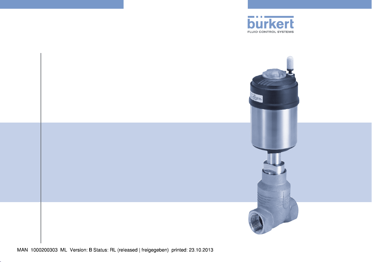
Type 2101
2/2-way Globe valve
2/2-Wege Geradsitzventil
Vanne à siège droit 2/2 voies
Quickstart
English Deutsch Français
Page 2
We reserve the right to make technical changes without notice.
Technische Änderungen vorbehalten.
Sous réserve de modifications techniques.
© 2013 Bürkert Werke GmbH
Operating Instructions 1308/01_EU-ML_00810250 / Original DE
Page 3
Type 2101
Quickstart
1. QUICKSTART .....................................................................................................3
2. SYMBOLS ............................................................................................................4
3. AUTHORIZED USE .........................................................................................4
4. BASIC SAFETY INSTRUCTIONS .............................................................5
5. GENERAL INFORMATION ...........................................................................6
6. TECHNICAL DATA ...........................................................................................7
7. INSTALLATION ..................................................................................................9
8. START-UP ......................................................................................................... 14
9. MAINTENANCE WORK .............................................................................. 15
10. REMOVAL .......................................................................................................15
11. PACKAGING, TRANSPORT, STORAGE .......................................... 15
1. QUICKSTART
The Quickstart describes the entire life cycle of the device. Keep these
instructions in a location which is easily accessible to every user, and
make these instructions available to every new owner of the device.
Important Safety Information!
Read Quickstart carefully and thoroughly. Study in particular the
chapters entitled “Basic safety instructions” and “Authorized use”.
• Quickstart must be read and understood.
Quickstart explains, for example, how to install and start-up the device.
A detailed description of the device can be found in the operating
instructions for Type 2101.
The operating instructions can be found on the Internet at:
www.burkert.com
1.1. Definition of term / abbreviation
The term “device” used in these instructions always stands for the
globe valve Type 2101.
The abbreviation “Ex” used in these instructions always stands for
“explosion-protected”.
english
3
Page 4
Type 2101
Symbols
2. SYMBOLS
DANGER!
Warns of an immediate danger.
• Failure to observe the warning may result in a fatal or serious injury.
WARNING!
Warns of a potentially dangerous situation.
• Failure to observe the warning may result in serious injuries or
death.
CAUTION!
Warns of a possible danger.
• Failure to observe this warning may result in a moderate or minor
injury.
NOTE!
Warns of damage to property.
Important tips and recommendations.
Refers to information in these operating instructions or in
other documentation.
3. AUTHORIZED USE
Non-authorized use of the globe valve Type 2101 may be a
hazard to people, nearby equipment and the environment.
• The device is designed for the controlled flow of liquid and
gaseous media.
• The admissible data, the operating conditions and conditions of
use specified in the contract documents, operating instructions
and on the type label are to be observed during use. These are
described in the chapter entitled “6. Technical data”.
• The device may be used only in conjunction with third-party devices
and components recommended and authorized by Bürkert.
• Correct transportation, correct storage and installation and
careful use and maintenance are essential for reliable and faultless operation.
• Use the device only as intended.
3.1. Restrictions
If exporting the system/device, observe any existing restrictions.
→ Designates a procedure which you must carry out.
4
english
Page 5
Type 2101
Basic safety instructions
4. BASIC SAFETY INSTRUCTIONS
These safety instructions do not make allowance for any
• contingencies and events which may arise during the installation,
operation and maintenance of the devices.
• local safety regulations, whereby the operator is responsible for their
compliance, by the installation personnel too.
DANGER!
Risk of injury from high pressure in the equipment/device!
• Before working on equipment or device, switch off the pressure
and deaerate/drain lines.
Risk of injury due to electrical shock!
• Before reaching into the device, switch off the power supply and
secure to prevent reactivation!
• Observe applicable accident prevention and safety regulations
for electrical equipment!
Risk of burns!
The surface of the device may become hot during long-term
operation.
• Do not touch the device with bare hands.
Risk of injury from moving parts in the device!
• Do not reach into openings.
Risk of injury caused by the spring jumping out when the
actuator is opened.
• The actuator must not be opened.
Risk of injury caused by the lines and device rupturing.
• Due to the risk of water hammer, valves with a flow direction
above the seat must not be used for liquid media.
• Consider the type of flow direction and the type of medium for
operation of the device.
General hazardous situations.
To prevent injury, ensure:
• In the potentially explosion-risk area the globe valve type 2101 may
be used only according to the specification on the separate Ex type
label. For use observe the additional information enclosed with the
device together with safety instructions for the explosion-risk area.
• Devices without a separate Ex type label may not be used in a
potentially explosive area.
• Secure system/equipment from unintentional activation.
• Only trained technicians may perform installation and maintenance
work.
• After an interruption in the power supply or pneumatic supply,
ensure that the process is restarted in a defined or controlled
manner.
• The device may be operated only when in perfect condition and
in consideration of the operating instructions.
• The general rules of technology apply to application planning and
operation of the device.
english
5
Page 6
Type 2101
General information
To prevent damage to property of the device, ensure:
• Supply the media connections only with those media which are
specified as flow media in the chapter entitled “6. Technical data”.
• Do not put any loads on the valve (e.g. by placing objects on it
or standing on it).
• Do not make any external modifications to the valves. Do not paint
the body parts or screws.
5. GENERAL INFORMATION
5.1. Contact address
Germany
Bürkert Fluid Control Systems
Sales Center
Chr.-Bürkert-Str. 13-17
D-74653 Ingelfingen
Tel. : 07940 - 10 91 111
Fax: 07940 - 10 91 448
E-mail: info@de.burkert.com
International
Contact addresses are found on the final pages of the printed operating manual.
You can also find information on the Internet under:
www.burkert.com
5.2. Warranty
The warranty is only valid if the device is used as authorized in accordance with the specified application conditions.
5.3. Information on the Internet
The operating instructions and data sheets for Type 2101 can be found
on the Internet at: www.burkert.com
6
english
Page 7
Type 2101
Technical data
6. TECHNICAL DATA
6.1. Conformity
In accordance with the EC Declaration of conformity, globe valve type
2101 is compliant with the EC Directives.
6.2. Standards
The applied standards, which verify conformity with the EC Directives,
can be found on the EC Type Examination Certificate and / or the EC
Declaration of Conformity.
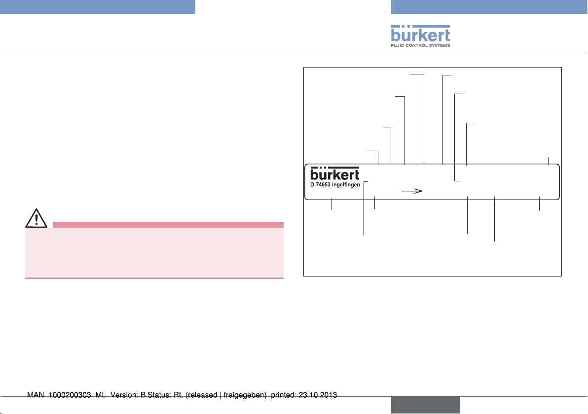
6.3. Type label
WARNING!
Risk of injury from high pressure!
Important device-specific technical specifications are indicated on
the type label.
• Observe permitted pressure range on the type label of the device.
Sealing material
Orifice of the body /
actuator size
Control function
(CF)
Type
2101 A 25M PTFE VA
Tmed -10°C - +180°C
00189700
ID number of
the device
Permitted medium
temperature
Fig. 1: Type label - example
Flow 1 2 DIN
Flow direction
Body material
Permitted medium
pressure
Pilot 4,8-10bar
Pmed 16,0bar
DN25 Kv13,0
Main dimensions
port connection
Permitted pilot
pressure
CE-Identification
CE
W3ZLT
Date of
manufacture
(encoded)
Flow capacity in
standard production
conditions
english
7
Page 8
Type 2101
Technical data
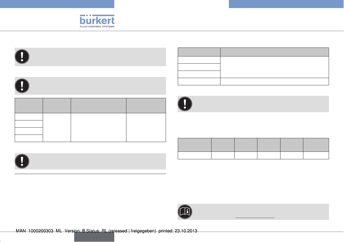
6.4. Operating conditions
Observe permitted ranges on the type label of the device!
6.4.1. Temperature ranges
The globe valve is suitable for steam sterilization.
Actuator
size
ø 50 mm
ø 70 mm
ø 90 mm
ø 130 mm
Tab. 1: Temperature ranges
2) Pilot air ports with push-in connector
3) Pilot air ports with threaded bushing
Actuator
material
Medium
(for PTFE seal)
PPS -10 ... +185 °C
1) If a pilot valve is used, the max. ambient temperature is
+55 °C.
Environment
0 ... +60 °C
0 ... +100 °C
6.4.2. Pressure ranges
Actuator size Maximum pilot pressure
4)
ø 50 mm
10 barø 70 mm
ø 90 mm
ø 130 mm 7 bar
Tab. 2: Pressure ranges
1)
2)
3)
Minimum pilot pressure: flow below the seat
(medium flow against the closing direction of the valve)
Required minimum pilot pressure P
The required minimum pilot pressure P
(flow below the seat) is dependent on the pressure of the medium 5).
4) For the device version ø 70 / Orifice 50 / MC 13 the
max. permitted pilot pressure is limited to 7 bar.
with control function A:
min
Actuator
size [mm]
[bar]
P
min
50 70 90 130
≤ DN 50
5,2 4,8 5,0 5,0 5,6
with control function B and I
min
130
≥ DN 65
Minimum pilot pressure: flow above the seat
(medium flow with the closing direction of the valve)
The required minimum pilot pressure P
(flow above the seat) is dependent on the pressure of the medium 5).
5) The pressure diagrams are in the operating instructions
with control function A
min
on the Internet: www.burkert.com
8
english
Page 9
Type 2101
Installation
6.5. General technical data
Media
Control medium Neutral gases, air
Flow media Water, alcohol, fuel, hydraulic liquids,
saline solutions, lye, organic solvents
Materials and
connections see data sheet or operating instructions
Installation as required, preferably with actuator in
upright position.
Protection class IP67 in accordance with IEC 529 /
EN 60529
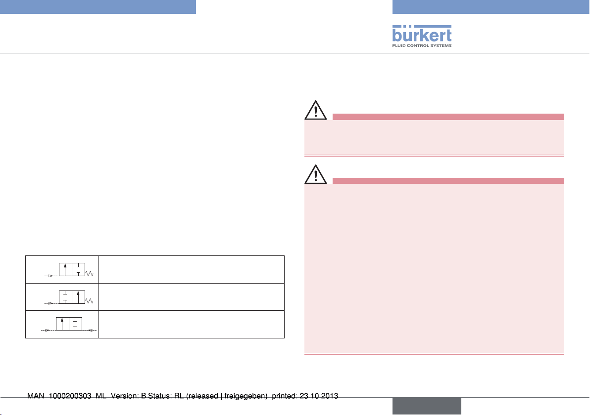
6.6. Control functions (CF)
A
B
I
Tab. 3: Control functions
2(A)
Normally closed by spring action.
1(P)
2(B)
Normally open by spring action.
1(P)
2(A)
Actuating function via reciprocal pressurization.
1(P)
7. INSTALLATION
7.1. Safety instructions
DANGER!
Risk of injury from high pressure!
• Before loosening the lines and valves, turn off the pressure and
vent the lines.
WARNING!
Risk of injury from improper installation!
• Installation may be carried out by authorized technicians only
and with the appropriate tools!
Risk of injury from unintentional activation of the system and
an uncontrolled restart!
• Secure system from unintentional activation.
• Following installation, ensure a controlled restart.
For control function I – Danger if pilot pressure fails!
For control function I control and resetting occur pneumatically. If
the pressure fails, no defined position is reached.
• To ensure a controlled restart, first pressurize the device with
pilot pressure, then switch on the medium.
Risk of injury from moving parts in the device!
• Do not reach into openings.
english
9
Page 10
Type 2101
Installation
7.2. Before installation
• The globe valve can be installed in any installation position, preferably with the actuator face up.
• Before connecting the valve, ensure the lines are flush.
• Observe direction of flow (see type label).
7.2.1. Preparatory work
→ Clean pipelines (sealing material, swarf, etc.).
Devices with welded body
Remove the actuator from the valve body:
→ Clamp the valve body in a holding device.
NOTE!
Damage to the seat seal or the seat contour!
• When removing the actuator, ensure that the valve is in open
position.
→ Control function A pressurize the pilot air port 1 with com-
pressed air (5 bar): valve opens.
→ Using a suitable open-end wrench, place the wrench flat on the
tube.
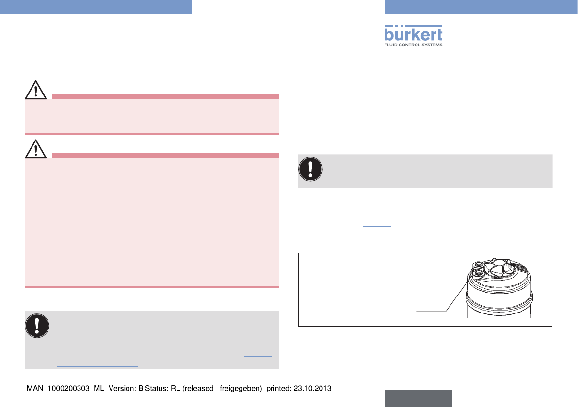
→ Unscrew the actuator from the valve body.
Other device versions
→ Do not remove actuator unless this is a customer-specific
requirement.
→ Procedure see “Devices with welded body”.
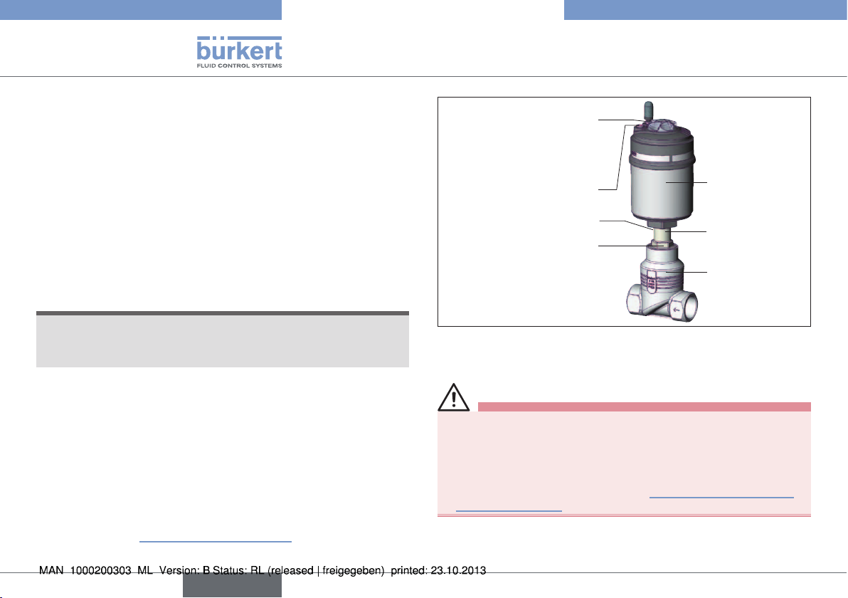
CFI
wrench
2
1
Actuator
Nipple
Valve body
Air discharge connection
CFA, CFB
Pilot air port
Pilot air port
CFA, CFB, CFI
Release bore
Flats for open-end
Fig. 2: Installation
7.3. Installation
WARNING!
Risk of injury from improper assembly!
Assembly with unsuitable tools or non-observance of the tightening torque is dangerous as the device may be damaged.
• For installation use an open-end wrench, never a pipe wrench.
• Observe the tightening torque (see “Tab. 4: Tightening torque
valve body / nipple”).
10
english
Page 11
Type 2101
Installation
Dirt trap for devices with authorization in accordance with DIN
EN 161
In accordance with DIN EN 161 „Automatic shut-off valves for gas
burners and gas appliances“ a dirt trap must be connected upstream
of the valve and prevent the insertion of a 1 mm plug gauge.
→ If the authorisation also applies to stainless steel bodies, the
same type of dirt trap must be attached in front of the globe
valve.
7.3.1. Installation of the valve body
Welded bodies
→ Weld valve body in pipeline system.
Other body versions
→ Connect body to pipeline.
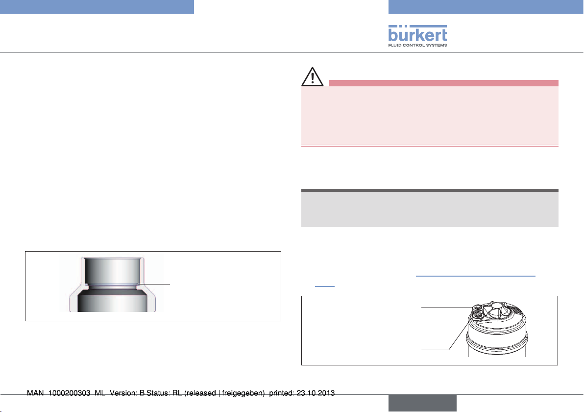
7.3.2. Install actuator (welded body)
Graphite seal
Fig. 3: Graphite seal
→ Check the graphite seal and if required, replace it.
WARNING!
Danger if incorrect lubricants used!
Unsuitable lubricant may contaminate the medium. In oxygen
applications there is a risk of an explosion!
• In specific applications, e.g. oxygen or analysis applications, use
appropriately authorised lubricants only.
→ Grease nipple thread before re-installing the actuator (e.g. with
Klüber paste UH1 96-402 from Klüber).
NOTE!
Damage to the seat seal or the seat contour!
• When installing the actuator, ensure that the valve is in open
position.
→ Control function A pressurize the pilot air port 1 with compressed
air (5 bar): valve opens.
→ Screw actuator into the valve body.
Observe tightening torque “Tab. 1: Temperature ranges Ex
area”).
Air discharge connection
CFA, CFB
Pilot air port CFI
Pilot air port
CFA, CFB, CFI
2
1
Fig. 4: Pneumatic connection
english
11
Page 12
Type 2101
Installation
DN Tightening torque [Nm]
15 45 ± 3
20 50 ± 3
25 60 ± 3
32
40
50 70 ± 3
65 100 ±3
80 120 ± 5
100 150 ± 5
Tab. 4: Tightening torque valve body / nipple
65 ± 3
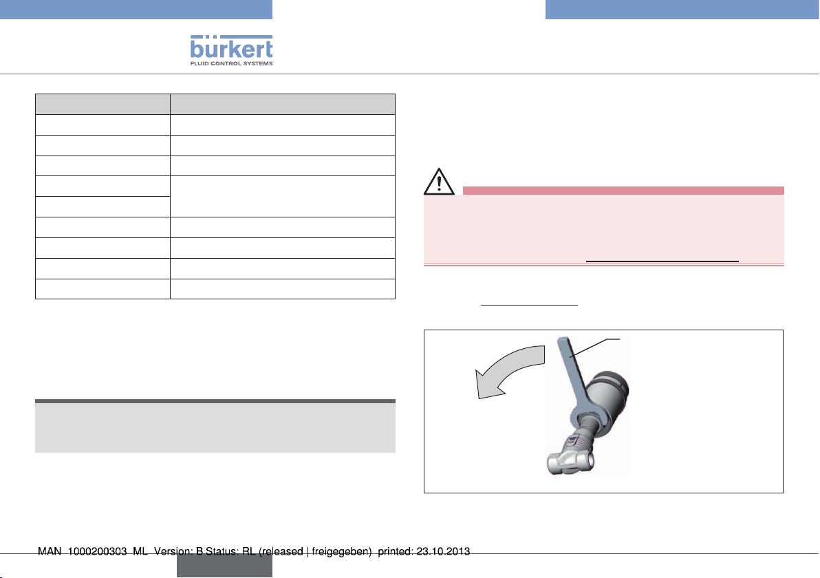
7.3.3. Rotating the actuator
The position of the connections can be aligned steplessly by rotating
the actuator through 360°.
NOTE!
Damage to the seat seal or the seat contour.
• When rotating the actuator, ensure that the valve is in open
position.
Procedure:
→ Clamp the valve body in a holding device
(applies only to valves which have not yet been installed).
→ Control function A pressurize the pilot air port 1 with com-
pressed air (5 bar): valve opens.
→ Counter on the flats of the nipple with a suitable open-end
wrench.
→ Place suitable open-end wrench on the hexagon of the actuator.
WARNING!
Risk of injury from discharge of medium and pressure.
If the direction of rotation is wrong, the body interface may become
detached.
• Rotate the actuator module in the specified direction only.
→ Actuator with hexagon:
Rotate counter-clockwise (as seen from below) to bring the
actuator module into the required position.
Open-end wrench
Fig. 5: Rotating with open-end wrench
12
english
Page 13
Type 2101
Installation
7.4. Pneumatic connection
DANGER!
Danger – high pressure in the equipment.
• Before loosening the lines and valves, turn off the pressure and
vent the lines.
WARNING!
Risk of injury from unsuitable connection hoses.
Hoses which cannot withstand the pressure and temperature range
may result in hazardous situations.
• Use only hoses which are authorised for the indicated pressure
and temperature range.
• Observe the data sheet specifications from the hose manufacturers.
For control function I – Danger if pilot pressure fails.
For control function I control and resetting occur pneumatically. If
the pressure fails, no defined position is reached.
• To ensure a controlled restart, first pressurize the device with
pilot pressure, then switch on the medium.
7.4.1. Connection of the control medium
If the position of the pilot air ports for installation of the
hoses is unfavorable, these can be aligned steplessly by
rotating the actuator through 360°.
The procedure is described in the chapter entitled “7.3.3.
Rotating the actuator”.
Control functions A and B:
→ Connect the control medium to the pilot air port 1 of the
actuator.
Silencer
For the versions with a plug-in connection the silencer for reducing
the exhaust air noise is supplied loose.
→ Plug the silencer into the free air discharge connection 2.
If used in an aggressive environment, we recommend
conveying all free pneumatic connections into a neutral
atmosphere with the aid of a pneumatic hose.
Control function I:
→ Connect the control medium to the pilot air port 1 and 2 of the
actuator (see “Fig. 6”)
Pressure on connection 1 opens the valve.
Pressure on connection 2 closes the valve.
Air discharge connection
CFA, CFB
Pilot air port CFI
Pilot air port
CFA, CFB, CFI
Fig. 6: Pneumatic connection
Control air hose:
6/4 mm or 1/4“ control air hoses can be used.
Optionally a pilot air port is possible via a G 1/8 thread.
2
1
english
13
Page 14
Type 2101
Start-up
8. START-UP
8.1. Safety instructions
WARNING!
Risk of injury from improper operation!
Improper operation may result in injuries as well as damage to the
device and the area around it.
• Before start-up, ensure that the operating personnel are familiar
with and completely understand the contents of the operating
instructions.
• Observe the safety instructions and intended use.
• Only adequately trained personnel may operate the equipment/
the device.
8.2. Pilot pressure
WARNING!
For control function I – Danger if pilot pressure fails!
For control function I control and resetting occur pneumatically. If
the pressure fails, no defined position is reached.
• To ensure a controlled restart, first pressurize the device with
pilot pressure, then switch on the medium.
→ Set the pilot pressure according to the type label specifications,
chapter “5” and flow (chapter “8.3”).
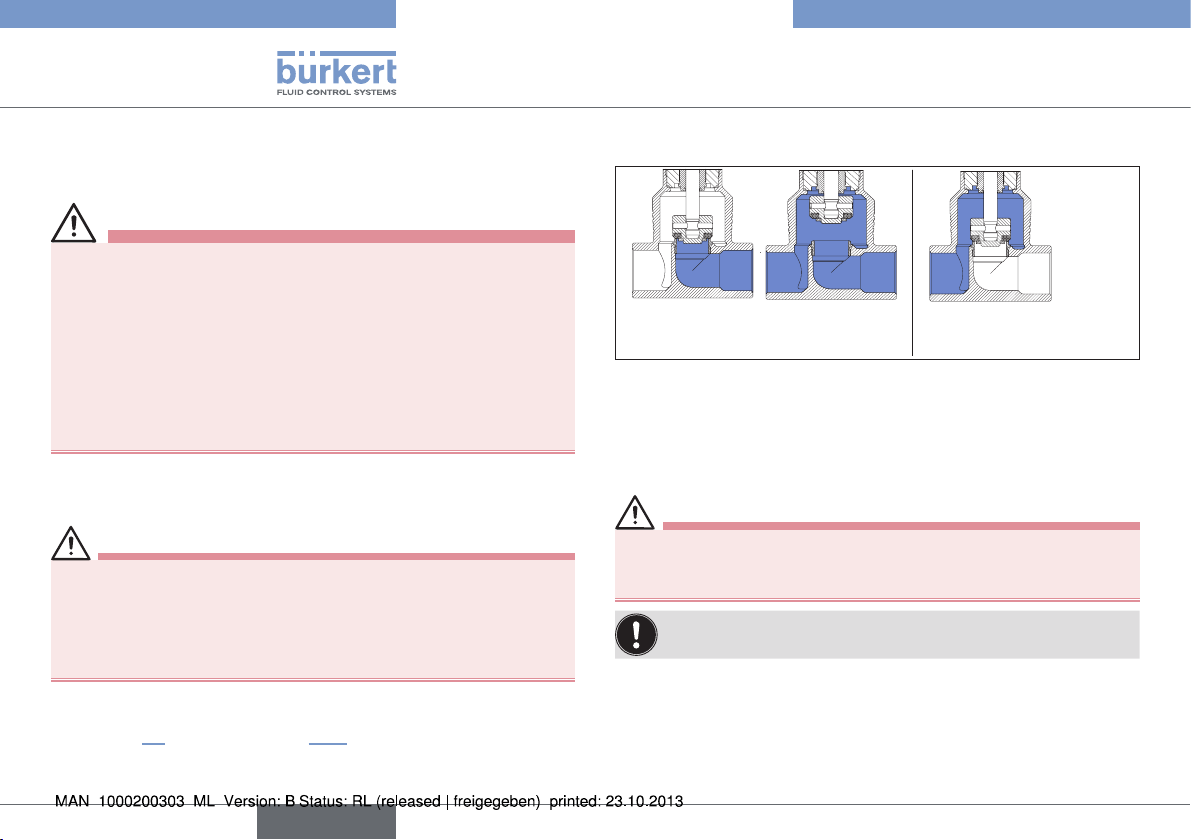
8.3. Flow
CFA
Flow below the seat
(closing against the medium)
Fig. 7: Flow below and above the seat
8.3.1. Flow above the seat
Control function A, CFA: closes by spring force against the medium flow.
Control function B, CFB: closes with the control pressure against the
medium flow. The medium pressure supports the opening of the valve.
WARNING!
Risk of injury caused by the lines and device rupturing.
• Use valves with flow above the seat for gaseous media and
steam only.
To ensure complete opening, the minimum pilot pressure must
be used.
8.3.2. Flow below the seat
Control function A, CFA: closes by spring force against the medium
flow. Control function B, CFB: closes with the control pressure
against the medium flow. The medium pressure supports the
opening of the valve.
CFB/CFI
CFA
Flow above the seat
(closing with the medium)
14
english
Page 15

Type 2101
Removal
WARNING!
Seat leaks caused by the minimum pilot pressure being too
low (on CFB and CFI) or the medium pressure being too high!
• Observe the minimum control pressure and medium pressure
(see “6.4.2”).
9. MAINTENANCE WORK
→ Complete a visual inspection of the equipment once a year. Shorter
maintenance intervals may be recommended depending on the
operating conditions.
9.1. Replacement parts
CAUTION!
Risk of injury and/or damage by the use of incorrect parts!
Incorrect accessories and unsuitable replacement parts may
cause injuries and damage the device and the surrounding area.
• Use only original accessories and original replacement parts
from Bürkert.
Wearing parts: Seals and the swivel plate.
→ In the event of a leak, replace the relevant wear part.
The maintenance and repair instructions are available on the
Internet: www.burkert.com
10. REMOVAL
DANGER!
Risk of injury from discharge of medium and pressure!
It is dangerous to remove a device which is under pressure due to
the sudden release of pressure or discharge of medium.
• Before removing a device, switch off the pressure and vent the lines.
Procedure:
→ Loosen the pneumatic connection.
→ Remove the device.
11. PACKAGING, TRANSPORT,
STORAGE
NOTE!
Transport and storage damage!
• Protect the device against moisture and dirt in shock-resistant
packaging during transportation and storage.
• Permitted storage temperature: -20 – +65°C.
Damage to the environment caused by device components
contaminated with media.
• Ensure the device and packaging are disposed of in an environmentally sound manner.
• Observe applicable regulations on disposal and the
environment.
english
15
Page 16

Type 2101
16
english
Page 17

Typ 2101
Der Quickstart
1. DER QUICKSTART ....................................................................................... 17
2. DARSTELLUNGSMITTEL ..........................................................................18
3. BESTIMMUNGSGEMÄSSE VERWENDUNG ...................................18
4. GRUNDLEGENDE SICHERHEITSHINWEISE ................................. 19
5. ALLGEMEINE HINWEISE .......................................................................... 20
6. TECHNISCHE DATEN ................................................................................ 21
7. MONTAGE ........................................................................................................23
8. INBETRIEBNAHME ......................................................................................28
9. WARTUNGSARBEITEN .............................................................................. 29
10. DEMONTAGE ...............................................................................................29
11. TRANSPORT, LAGERUNG, ENTSORGUNG .................................29
1. DER QUICKSTART
Der Quickstart beschreibt den gesamten Lebenszyklus des Geräts.
Bewahren Sie diese Anleitung so auf, dass sie für jeden Benutzer gut
zugänglich ist und jedem neuen Eigentümer des Geräts wieder zur
Verfügung steht.
Wichtige Informationen zur Sicherheit!
Lesen Sie den Quickstart sorgfältig durch. Beachten Sie vor allem
die Kapitel „Grundlegende Sicherheitshinweise“ und „Bestimmungsgemäße Verwendung“.
• Der Quickstart muss gelesen und verstanden werden.
Der Quickstart erläutert beispielhaft die Montage und Inbetriebnahme
des Geräts.
Die ausführliche Beschreibung des Geräts finden Sie in der Bedienungsanleitung für den Typ 2101.
Die Bedienungsanleitung finden Sie im Internet unter:
www.buerkert.de
1.1. Begriffsdefinition / Abkürzung
Der in dieser Anleitung verwendeten Begriff „Gerät“ steht immer für
das Geradsitzventil Typ 2101.
Die in dieser Anleitung verwendete Abkürzung „Ex“ steht immer für
„explosionsgeschützt“.
deutsch
17
Page 18

Typ 2101
Darstellungsmittel
2. DARSTELLUNGSMITTEL
GEFAHR!
Warnt vor einer unmittelbaren Gefahr!
• Bei Nichtbeachtung sind Tod oder schwere Verletzungen die
Folge.
WARNUNG!
Warnt vor einer möglicherweise gefährlichen Situation!
• Bei Nichtbeachtung können schwere Verletzungen oder Tod die
Folge sein.
VORSICHT!
Warnt vor einer möglichen Gefährdung!
• Nichtbeachtung kann mittelschwere oder leichte Verletzungen
zur Folge haben.
HINWEIS!
Warnt vor Sachschäden!
Wichtige Tipps und Empfehlungen.
verweist auf Informationen in dieser Bedienungsanleitung
oder in anderen Dokumentationen.
3. BESTIMMUNGSGEMÄSSE
VERWENDUNG
Bei nicht bestimmungsgemäßem Einsatz des Geradsitzventils
Typ 2101 können Gefahren für Personen, Anlagen in der
Umgebung und die Umwelt entstehen.
• Das Gerät ist für die Steuerung des Durchflusses von flüssigen
und gasförmigen Medien konzipiert.
• Für den Einsatz die in den Vertragsdokumenten und der Bedienungsanleitung spezifizierten zulässigen Daten, Betriebs- und
Einsatzbedingungen beachten. Diese sind im Kapitel „7. Technische Daten“ beschrieben.
• Das Gerät nur in Verbindung mit von Bürkert empfohlenen bzw.
zugelassenen Fremdgeräten und -komponenten einsetzen.
• Voraussetzungen für den sicheren und einwandfreien Betrieb
sind sachgemäßer Transport, sachgemäße Lagerung und Installation sowie sorgfältige Bedienung und Instandhaltung.
• Das Gerät nur bestimmungsgemäß einsetzen.
3.1. Beschränkungen
Beachten Sie bei der Ausfuhr des Systems/Geräts gegebenenfalls
bestehende Beschränkungen.
→ markiert einen Arbeitsschritt den Sie ausführen müssen.
18
deutsch
Page 19

Typ 2101
Grundlegende Sicherheitshinweise
4. GRUNDLEGENDE
SICHERHEITSHINWEISE
Diese Sicherheitshinweise berücksichtigen keine
• Zufälligkeiten und Ereignisse, die bei Montage, Betrieb und Wartung
der Geräte auftreten können.
• ortsbezogenen Sicherheitsbestimmungen, für deren Einhaltung, auch
in Bezug auf das Montagepersonal, der Betreiber verantwortlich ist.
Verletzungsgefahr durch hohen Druck in Anlage/Gerät!
• Vor Arbeiten an Anlage oder Gerät, den Druck abschalten und
Leitungen entlüften/entleeren.
Verletzungsgefahr durch Stromschlag!
• Vor Arbeiten an Anlage oder Gerät, die Spannung abschalten
und vor Wiedereinschalten sichern.
• Die geltenden Unfallverhütungs- und Sicherheitsbestimmungen
für elektrische Geräte beachten!
Verbrennungsgefahr!
Bei Dauerbetrieb kann die Geräteoberfläche heiß werden.
• Das Gerät nicht mit bloßen Händen berühren.
Verletzungsgefahr durch sich bewegende Teile im Gerät!
• Nicht in Öffnungen fassen.
Verletzungsgefahr durch herausspringende Feder beim Öffnen
des Antriebs!
• Der Antrieb darf nicht geöffnet werden.
Verletzungsgefahr durch Bersten von Leitungen und Gerät.
• Wegen Schließschlaggefahr dürfen Ventile mit Anströmung über
Sitz nicht für flüssige Medien eingesetzt werden.
• Für den Betrieb des Geräts die Art der Anströmung und die Art
des Mediums beachten.
Allgemeine Gefahrensituationen.
Zum Schutz vor Verletzungen beachten:
• Im explosionsgefährdeten Bereich darf das Geradsitzventil Typ
2101 nur entsprechend der Spezifikation auf dem separaten ExTypschild eingesetzt werden. Für den Einsatz muss die dem Gerät
beiliegende Zusatzinformation mit Sicherheitshinweisen für den
Ex-Bereich beachtet werden.
• Geräte ohne separates Ex-Typschild dürfen nicht im explosionsgefährdeten Bereich eingesetzt werden.
• Anlage / Gerät vor unbeabsichtigtem Betätigen sichern.
• Nur geschultes Fachpersonal darf Installations- und Instandhaltungsarbeiten ausführen.
• Nach einer Unterbrechung der elektrischen oder pneumatischen
Versorgung ist ein definierter oder kontrollierter Wiederanlauf
des Prozesses zu gewährleisten.
• Gerät nur in einwandfreiem Zustand und unter Beachtung der
Bedienungsanleitung betreiben.
• Für die Einsatzplanung und den Betrieb des Geräts die allgemeinen
Regeln der Technik einhalten.
deutsch
19
Page 20

Typ 2101
Allgemeine Hinweise
Zum Schutz vor Sachschäden am Gerät ist zu beachten:
• In Medienanschlüsse nur Medien einspeisen, die im Kapitel „7.
Technische Daten“ aufgeführt sind.
• Gerät nicht mechanisch belasten (z. B. durch Ablage von Gegenständen oder als Trittstufe).
• Keine äußerlichen Veränderungen an den Ventilen vornehmen.
Gehäuseteile und Schrauben nicht lackieren.
5. ALLGEMEINE HINWEISE
5.1. Kontaktadresse
Deutschland
Bürkert Fluid Control Systems
Sales Center
Christian-Bürkert-Str. 13-17
D-74653 Ingelfingen
Tel. + 49 (0) 7940 - 10 91 111
Fax + 49 (0) 7940 - 10 91 448
E-mail: info@de.buerkert.com
International
Die Kontaktadressen finden Sie auf den letzten Seiten der
gedruckten Bedienungsanleitung.
Außerdem im Internet unter: www.burkert.com
5.2. Gewährleistung
Voraussetzung für die Gewährleistung ist der bestimmungsgemäße Gebrauch des Geräts unter Beachtung der spezifizierten
Einsatzbedingungen.
5.3. Informationen im Internet
Bedienungsanleitungen und Datenblätter zum Typ 2101 finden Sie im
Internet unter: www.buerkert.de
20
deutsch
Page 21

Typ 2101
Technische Daten
6. TECHNISCHE DATEN
6.1. Konformität
Das Geradsitzventil Typ 2101 ist konform zu den EG-Richtlinien entsprechend der EG-Konformitätserklärung.
6.2. Normen
Die angewandten Normen, mit denen die Konformität mit den EG-Richtlinien nachgewiesen wird, sind in der EG-Baumusterprüfbescheinigung
und/oder der EG-Konformitätserklärung nachzulesen.
6.3. Typschild
WARNUNG!
Verletzungsgefahr durch hohen Druck.
Wichtige gerätespezifische technische Angaben sind auf dem
Typschild angegeben.
• Zulässiger Druckbereich auf dem Typschild des Geräts beachten.
Dichtungswerkstoff
Nennweite Gehäuse /
Antriebsgröße
Steuerfunktion (SF)
Typ
2101 A 25M PTFE VA
Tmed -10°C - +180°C
00189700
Identnummer
des Geräts
Mediumstemperatur
Bild 1: Typschild - Beispiel
Flow 1 2 DIN
Durchflussrichtung
Zulässige
Gehäusewerkstoff
Pilot 4,8-10bar
Pmed 16,0bar
DN25 Kv13,0
Hauptmaße
Leitungsanschluss
Zulässiger
Mediumsdruck
Zulässiger
Steuerdruck
CE-Kennzeichnung
CE
W3ZLT
Herstellerdatum
(verschlüsselt)
Durchflusskapazität in
Serienbedingungen
deutsch
21
Page 22

Typ 2101
Technische Daten
6.4. Betriebsbedingungen
Die zulässigen Bereiche auf dem Typschild des Geräts
beachten!
6.4.1. Temperaturbereiche
Das Geradsitzventil ist für die Dampfsterilisation geeignet.
Antriebs-
größe
ø 50 mm
ø 70 mm
ø 90 mm
ø 130 mm
Tab. 1: Temperaturbereiche
2) Steuerluftanschlüsse als Schlauchsteckverbinder
3) Steuerluftanschlüsse als Gewindebuchse
Antriebswerkstoff
Medium
(bei PTFE-Dichtung)
PPS -10 ... +185 °C
1) Bei Verwendung eines Vorsteuerventils beträgt die max.
Umgebungstemperatur +55 °C.
Umgebung
0 ... +60 °C
0 ... +100 °C
6.4.2. Druckbereiche
Antriebsgröße Maximaler Steuerdruck
4)
ø 50 mm
10 barø 70 mm
ø 90 mm
ø 130 mm 7 bar
Tab. 2: Druckbereiche
1)
2)
Mindeststeuerdrücke: Anströmung unter Sitz
(Mediumsstrom gegen Ventilschließrichtung)
3)
Erforderlicher Mindeststeuerdruck P
Der erforderliche Mindeststeuerdruck P
(Anströmung unter Sitz) ist abhängig vom Mediumsdruck 5).
4) Für die Gerätevariante ø 70 / DN 50 / MC 13
ist der max. zulässige Steuerdruck auf 7 bar begrenzt.
min
Antriebs-
50 70 90 130
größe [mm]
[bar]
P
min
5,2 4,8 5,0 5,0 5,6
bei Steuerfunktion A:
≤ DN 50
bei Steuerfunktion B und I
min
≥ DN 65
130
Mindestdrücke: Anströmung über Sitz
(Mediumsstrom mit Ventilschließrichtung)
Der erforderliche Mindeststeuerdruck P
(Anströmung über Sitz) ist abhängig vom Mediumsdruck 5).
bei Steuerfunktion A
min
22
5) Die Druckdiagramme finden Sie in der Bedienungsanleitung im
Internet unter: www.buerkert.de
deutsch
Page 23

Typ 2101
Montage
6.5. Allgemeine Technische Daten
Medien
Steuermedium neutrale Gase, Luft
Durchflussmedien Wasser, Alkohole, Treibstoffe, Hydraulik-
flüssigkeiten, Salzlösungen, Laugen, organische Lösungsmittel
Werkstoffe und
Anschlüsse siehe Datenblatt oder
Bedienungsanleitung
Einbaulage beliebig, vorzugsweise Antrieb nach oben
Schutzart IP67 nach IEC 529 / EN 60529
6.6. Steuerfunktion (SF)
A
B
I
Tab. 3: Steuerfunktionen
2(A)
In Ruhestellung durch Federkraft geschlossen
1(P)
2(B)
In Ruhestellung durch Federkraft geöffnet
1(P)
2(A)
Stellfunktion über wechselseitige
Druckbeaufschlagung
1(P)
7. MONTAGE
7.1. Sicherheitshinweise
GEFAHR!
Verletzungsgefahr durch hohen Druck in der Anlage!
• Vor dem Lösen von Leitungen und Ventilen den Druck abschalten und Leitungen entlüften.
WARNUNG!
Verletzungsgefahr bei unsachgemäßer Montage!
• Die Montage darf nur autorisiertes Fachpersonal mit geeignetem
Werkzeug durchführen!
Verletzungsgefahr durch ungewolltes Einschalten der Anlage
und unkontrollierten Wiederanlauf!
• Anlage vor unbeabsichtigtem Betätigen sichern.
• Nach der Montage einen kontrollierten Wiederanlauf
gewährleisten.
Bei Steuerfunktion I – Gefahr bei Steuerdruckausfall!
Bei Steuerfunktion I erfolgt die Ansteuerung und Rückstellung
pneumatisch. Bei Druckausfall wird keine definierte Position erreicht.
• Für einen kontrollierten Wiederanlauf das Gerät zunächst mit
Steuerdruck beaufschlagen, danach erst das Medium aufschalten.
Verletzungsgefahr durch sich bewegende Teile im Gerät!
• Nicht in Öffnungen fassen.
deutsch
23
Page 24

Typ 2101
Montage
7.2. Vor dem Einbau
• Die Einbaulage des Geradsitzventils ist beliebig, vorzugsweise
Antrieb nach oben.
• Vor dem Anschluss des Ventils auf fluchtende Rohrleitungen
achten.
• Durchflussrichtung beachten (siehe Typschild).
7.2.1. Vorbereitende Arbeiten
→ Rohrleitungen von Verunreinigungen säubern (Dichtungsmaterial,
Metallspäne, usw.).
Geräte mit Schweißgehäuse
Antrieb vom Ventilgehäuse demontieren:
→ Ventilgehäuse in eine Haltevorrichtung einspannen.
HINWEIS!
Beschädigung der Sitzdichtung bzw. der Sitzkontur!
• Das Ventil muss sich bei der Demontage des Antriebs in geöffneter Stellung befinden.
→ Bei Steuerfunktion A den Steuerluftanschluss 1 mit Druckluft (5 bar)
beaufschlagen: Ventil öffnet.
→ An der Schlüsselfläche des Nippels mit passendem Gabelschlüssel
ansetzen.
→ Antrieb vom Ventilgehäuse abschrauben.
Andere Geräteausführungen
→ Antrieb nur bei kundenspezifischer Erfordernis demontieren.
→ Vorgehensweise siehe „Geräte mit Schweißgehäuse“.
SFI
2
1
Antrieb
Nippel
Ventilgehäuse
Entlüftungsanschluss
SFA, SFB
Steuerluftanschluss
Steuerluftanschluss
SFA, SFB, SFI
Entlastungsbohrung
Schlüsselfläche für
Gabelschlüssel
Bild 2: Einbau
7.3. Einbau
WARNUNG!
Verletzungsgefahr bei unsachgemäßem Einbau!
Der Einbau mit ungeeignetem Werkzeug oder das Nichtbeachten
des Anziehdrehmoments ist wegen der möglichen Beschädigung
des Geräts gefährlich.
• Zur Montage einen Gabelschlüssel, keinesfalls eine Rohrzange
verwenden.
• Anziehdrehmoment beachten (siehe „Tab. 4: Anziehdrehmomente Ventilgehäuse / Nippel“).
24
deutsch
Page 25

Typ 2101
Montage
Schmutzfänger für Geräte mit Zulassung nach DIN EN 161
Nach DIN EN 161 „Automatische Absperrventile für Gasbrenner und
Gasgeräte“ muss dem Ventil ein Schmutzfänger vorgeschaltet werden,
der das Eindringen eines 1 mm - Prüfdorns verhindert.
→ Soll die Zulassung auch für Edelstahlgehäuse gelten, ist ein der-
artiger Schmutzfänger vor dem Geradsitzventil anzubringen.
7.3.1. Gehäuse montieren
Schweißgehäuse
→ Ventilgehäuse in Rohrleitungssystem einschweißen.
Andere Gehäuseausführungen
→ Gehäuse mit Rohrleitung verbinden.
7.3.2. Antrieb montieren (Schweißgehäuse)
Graphitdichtung
Bild 3: Graphitdichtung
→ Graphitdichtung prüfen und bei Bedarf erneuern.
WARNUNG!
Gefahr durch falsche Schmierstoffe!
Ungeeigneter Schmierstoff kann das Medium verunreinigen. Bei
Sauerstoffanwendungen besteht dadurch Explosionsgefahr!
• Bei spezifischen Anwendungen wie z. B. Sauerstoff - oder Analyseanwendungen nur entsprechend zugelassene Schmierstoffe
verwenden.
→ Nippelgewinde vor Wiedereinbau des Antriebes einfetten (z. B.
mit Klüberpaste UH1 96-402 der Fa. Klüber).
HINWEIS!
Beschädigung der Sitzdichtung bzw. der Sitzkontur!
• Das Ventil muss sich bei der Montage des Antriebs in geöffneter Stellung befinden.
→ Bei Steuerfunktion A den Steuerluftanschluss 1 mit Druckluft
(5 bar) beaufschlagen: Ventil öffnet.
→ Antrieb in das Ventilgehäuse einschrauben. Anziehdrehmoment
beachten (siehe „Tab. 4: Anziehdrehmomente Ventilgehäuse /
Nippel“).
Entlüftungsanschluss
SFA, SFB
Steuerluftanschluss
Steuerluftanschluss
SFA, SFB, SFI
2
SFI
1
Bild 4: Anschlüsse
deutsch
25
Page 26

Typ 2101
Montage
DN Anziehdrehmoment [Nm]
15 45 ± 3
20 50 ± 3
25 60 ± 3
32
40
50 70 ± 3
65 100 ±3
80 120 ± 5
100 150 ± 5
Tab. 4: Anziehdrehmomente Ventilgehäuse / Nippel
65 ± 3
7.3.3. Drehen des Antriebs
Die Position der Anschlüsse kann durch Verdrehen des Antriebs um
360° stufenlos ausgerichtet werden.
HINWEIS!
Beschädigung der Sitzdichtung bzw. der Sitzkontur!
• Das Ventil muss sich bei beim Drehen des Antriebs in geöffneter Stellung befinden.
Vorgehensweise:
→ Das Ventilgehäuse in eine Haltevorrichtung einspannen
(gilt nur für noch nicht eingebaute Ventile).
→ Bei Steuerfunktion A den Steuerluftanschluss 1 mit Druckluft
(5 bar) beaufschlagen: Ventil öffnet.
→ An der Schlüsselfläche des Nippels mit passendem Gabelschlüssel
gegenhalten.
→ Antrieb mit Sechskantkontur:
Passender Gabelschlüssel am Sechskant des Antriebs ansetzen.
WARNUNG!
Verletzungsgefahr durch Mediumsaustritt und Druckentladung!
Bei falscher Drehrichtung kann sich die Gehäuseschnittstelle lösen.
• Den Antrieb nur im vorgegebenen Richtungssinn drehen!
→ Antrieb mit Sechskantkontur:
Durch Drehen gegen den Uhrzeigersinn (von unten gesehen)
den Antrieb in die gewünschte Position bringen.
Gabelschlüssel
Bild 5: Drehen mit Gabelschlüssel
26
deutsch
Page 27

Typ 2101
Montage
7.4. Pneumatischer Anschluss
GEFAHR!
Verletzungsgefahr durch hohen Druck in der Anlage!
• Vor dem Lösen von Leitungen und Ventilen den Druck abschalten und Leitungen entlüften.
WARNUNG!
Verletzungsgefahr durch ungeeignete Anschlussschläuche!
Schläuche die dem Druck- und Temperaturbereich nicht standhalten,
können zu gefährlichen Situationen führen.
• Nur Schläuche verwenden, die für den angegeben Druck- und
Temperaturbereich zugelassen sind.
• Die Datenblattangaben der Schlauchhersteller beachten.
Bei Steuerfunktion I – Gefahr bei Steuerdruckausfall!
Bei Steuerfunktion I erfolgt die Ansteuerung und Rückstellung
pneumatisch. Bei Druckausfall wird keine definierte Position erreicht.
• Für einen kontrollierten Wiederanlauf, das Gerät zunächst mit
Steuerdruck beaufschlagen, danach erst das Medium aufschalten.
7.4.1. Anschluss des Steuermediums
Sollte die Position der Steuerluftanschlüsse für die Montage
der Schläuche ungünstig sein, können diese durch Verdrehen
des Antriebs um 360° stufenlos ausgerichtet werden.
Die Vorgehensweise ist im Kapitel „7.3.3. Drehen des
Antriebs“ beschrieben.
Steuerfunktion A und B:
→ Steuermedium an Steuerluftanschluss 1 des Antriebs anschließen.
Schalldämpfer
Bei den Ausführungen mit Steckanschluss wird der Schalldämpfer
zur Reduzierung der Abluftlautstärke lose mitgeliefert.
→ Schalldämpfer in den freien Entlüftungsanschluss 2 stecken.
Beim Einsatz in aggressiver Umgebung empfehlen wir,
sämtliche freien Pneumatikanschlüsse mit Hilfe eines
Pneumatikschlauches in neutrale Atmosphäre abzuleiten.
Steuerfunktion I:
→ Steuermedium an Steuerluftanschluss 1 und 2 des Antriebs
anschließen (siehe „Bild 6“)
Druck am Steuerluftanschluss 1 öffnet das Ventil.
Druck am Steuerluftanschluss 2 schließt das Ventil.
Entlüftungsanschluss
SFA, SFB
Steuerluftanschluss
Steuerluftanschluss
SFA, SFB, SFI
Bild 6: Anschlüsse
Steuerluftschlauch:
Es können Steuerluftschläuche der Größen 6/4 mm bzw. 1/4“ verwendet werden.
Optional ist ein Steuerluftanschluss über G 1/8 Gewinde möglich.
2
SFI
1
deutsch
27
Page 28

Typ 2101
deutsch
Inbetriebnahme
8. INBETRIEBNAHME
8.1. Sicherheitshinweise
WARNUNG!
Verletzungsgefahr bei unsachgemäßem Betrieb!
Nicht sachgemäßer Betrieb kann zu Verletzungen, sowie Schäden
am Gerät und seiner Umgebung führen.
• Vor der Inbetriebnahme muss gewährleistet sein, dass der Inhalt
der Bedienungsanleitung dem Bedienungspersonal bekannt ist
und vollständig verstanden wurde.
• Die Sicherheitshinweise und die bestimmungsgemäße Verwendung müssen beachtet werden.
• Nur ausreichend geschultes Personal darf die Anlage/das Gerät
in Betrieb nehmen.
8.2. Steuerdruck
WARNUNG!
Bei Steuerfunktion I - Gefahr bei Steuerdruckausfall!
Bei Druckausfall wird keine definierte Position erreicht.
• Für einen kontrollierten Wiederanlauf, das Gerät zunächst mit
Steuerdruck beaufschlagen, danach erst das Medium aufschalten.
→ Steuerdruck entprechend Typschildangaben, Kapitel „5“ und
Anströmung (Kapitel „8.3“) einstellen.
8.3. Anströmung
SFA
Anströmung unter Sitz
(gegen Medium schließend)
Bild 7: Anströmung unter und über Sitz
8.3.1. Anströmung über Sitz
Steuerfunktion A, SFA: schließt mit Federkraft mit dem Mediumsstrom. Der
Mediumsdruck unterstützt das Schließen und Abdichten des Ventilsitzes.
Das Öffnen des Ventils erfolgt durch den Steuerdruck.
WARNUNG!
Verletzungsgefahr durch Bersten von Leitungen und Gerät!
• Ventile mit Anströmung über Sitz nur für gasförmige Medien und
Dampf einsetzen.
Um ein vollständiges Öffnen zu gewährleisten, muss der
Mindeststeuerdruck eingesetzt werden!
8.3.2. Anströmung unter Sitz
Steuerfunktion A, SFA: schließt mit Federkraft gegen Mediumsstrom.
Steuerfunktion B, SFB: schließt mit Steuerdruck gegen Mediumsstrom.
Der Mediumsdruck unterstützt das Öffnen des Ventils.
SFB/SFI
SFA
Anströmung über Sitz
(mit Medium schließend)
28
Page 29

Typ 2101
Demontage
WARNUNG!
Sitzundichtheit bei zu geringem Mindeststeuerdruck (bei SFB
und SFI) oder zu hohem Mediumsdruck!
• Mindeststeuerdruck und Mediumsdruck beachten (siehe „6.4.2.
Druckbereiche“.
9. WARTUNGSARBEITEN
→ Sichtkontrolle einmal pro Jahr am Gerät durchführen. Je nach Ein-
satzbedingungen werden kürzere Wartungsintervalle empfohlen.
9.1. Ersatzteile
VORSICHT!
Verletzungsgefahr, Sachschäden durch falsche Teile!
Falsches Zubehör und ungeeignete Ersatzteile können Verletzungen
und Schäden am Gerät und dessen Umgebung verursachen.
• Nur Originalzubehör sowie Originalersatzteile der Firma Bürkert
verwenden.
Verschleißteile: Dichtungen und Pendelteller.
→ Bei Undichtheiten das jeweilige Verschleißteil austauschen.
Die Wartungs- und Reparaturanleitung befindet sich im
Internet: www.buerkert.de
10. DEMONTAGE
GEFAHR!
Verletzungsgefahr durch hohen Druck in der Anlage!
• Vor dem Lösen von Leitungen oder Ventilen den Druck abschalten und Leitungen entlüften.
Verletzungsgefahr durch Stromschlag!
• Vor Eingriffen in das Gerät oder die Anlage, Spannung abschalten und vor Wiedereinschalten sichern!
Vorgehensweise:
→ Pneumatischer Anschluss lösen.
→ Gerät demontieren.
11. TRANSPORT, LAGERUNG,
ENTSORGUNG
HINWEIS!
Transportschäden und Lagerschäden!
• Gerät vor Nässe und Schmutz geschützt in einer stoßfesten
Verpackung transportieren und lagern.
• Lagertemperatur -20 … +65 °C.
Umweltschäden durch von Medien kontaminierte Geräteteile.
• Gerät und Verpackung umweltgerecht entsorgen!
• Geltende Entsorgungsvorschriften und Umweltbestimmungen
einhalten.
deutsch
29
Page 30

Typ 2101
30
deutsch
Page 31

Type 2101
Quickstart
1. QUICKSTART ..................................................................................................31
2. SYMBOLES ...................................................................................................... 32
3. UTILISATION CONFORME.......................................................................32
4. CONSIGNES DE SÉCURITÉ FONDAMENTALES .........................33
5. INDICATIONS GÉNÉRALES .................................................................... 34
6. CARACTÉRISTIQUES TECHNIQUES .................................................. 35
7. MONTAGE ........................................................................................................37
8. MISE EN SERVICE ....................................................................................... 42
9. TRAVAUX DE MAINTENANCE ...............................................................43
10. DÉMONTAGE ...............................................................................................44
11. EMBALLAGE, TRANSPORT, STOCKAGE ...................................... 44
1. QUICKSTART
Quickstart décrit le cycle de vie complet de l’appareil. Conservez ce
manuel de sorte qu’il soit accessible à tout utilisateur et à disposition
de tout nouveau propriétaire.
Informations importantes pour la sécurité.
Lisez attentivement Quickstart. Tenez compte en particulier des
chapitres « Consignes de sécurité fondamentales » et « Utilisation
conforme ».
• Ce manuel Quickstart doit être lu et compris.
Quickstart explique par des exemples le montage et la mise en service
de l’appareil.
Vous trouverez la description détaillée de l’appareil dans le manuel
d’utilisation du type 2101.
Vous trouverez le manuel d’utilisation sur Internet sous :
www.buerkert.fr
1.1. Définition du terme / abréviation
Le terme « appareil » utilisé dans ce manuel désigne toujours la vanne
à siège droit type 2101.
L’abréviation « Ex » utilisé dans ce manuel désigne toujours «protégée
contre les explosions ».
français
31
Page 32

Type 2101
Symboles
2. SYMBOLES
DANGER !
Met en garde contre un danger imminent.
• Le non-respect peut entraîner la mort ou de graves blessures.
AVERTISSEMENT !
Met en garde contre une situation éventuellement
dangereuse.
• Risque de blessures graves, voire la mort en cas de non-respect.
ATTENTION !
Met en garde contre un risque possible.
• Le non-respect peut entraîner des blessures légères ou de
moyenne gravité.
REMARQUE !
Met en garde contre des dommages matériels.
désigne des informations complémentaires importantes, des
conseils et des recommandations.
renvoie à des informations dans ces manuels d’utilisation ou
dans d'autres documentations.
3. UTILISATION CONFORME
L'utilisation non conforme de la vanne à siège droit type 2101
peut présenter des dangers pour les personnes, les installations
proches et l'environnement.
• L'appareil a été conçu pour la commande du débit de fluides
liquides et gazeux.
• Lors de l'utilisation, il convient de respecter les données et conditions d'utilisation et d'exploitation admissibles spécifiées dans les
documents contractuels, les manuels d’utilisation et sur la plaque
signalétique. Celles-ci sont décrites au chapitre « 6. Caractéristiques techniques ».
• L'appareil peut être utilisé uniquement en association avec les
appareils et composants étrangers recommandés et homologués
par Bürkert.
• Les conditions pour l'utilisation sûre et parfaite sont un transport,
un stockage et une installation dans les règles ainsi qu'une parfaite
utilisation et maintenance.
• Veillez à ce que l'utilisation de l'appareil soit toujours conforme.
3.1. Restrictions
Lors de l‘exportation du système/de l‘appareil, veuillez respecter les
limitations éventuelles existantes.
→ identifie une opération que vous devez effectuer.
32
français
Page 33

Type 2101
Consignes de sécurité fondamentales
4. CONSIGNES DE SÉCURITÉ
FONDAMENTALES
Ces consignes de sécurité ne tiennent pas compte
• des hasards et des événements pouvant survenir lors du montage,
de l‘exploitation et de l‘entretien des appareils.
• des prescriptions de sécurité locales que l‘exploitant est tenu de
faire respecter par le personnel chargé du montage.
Risque de blessures dû à la présence de haute pression dans
l‘installation/l‘appareil.
• Avant de travailler sur l’installation ou l’appareil, il convient de
couper la pression et de purger l’air des conduites/de les vider.
Risque de choc électrique.
• Avant d’intervenir dans l’appareil ou l’installation, coupez la tension
et empêchez toute remise sous tension par inadvertance.
• Veuillez respecter les réglementations en vigueur pour les appareils
électriques en matière de prévention des accidents ainsi qu’en
matière de sécurité.
Risque de brûlures.
La surface d’appareil peut devenir brûlante en fonctionnement continu.
• Ne pas toucher l’appareil à mains nues.
Risque de blessures dû aux pièces en mouvement dans l’appareil.
• Ne pas intervenir dans les ouvertures.
Risque de blessures dû la sortie du ressort à l‘ouverture de
l’actionneur.
• L‘ouverture de l‘actionneur n‘est pas autorisée.
Risque de blessures dû à la rupture de conduites et de l‘appareil.
• Étant donné le risque de coups de bélier, les vannes avec arrivée
du fluide sur le siège ne doivent pas être utilisées pour les fluides
liquides.
• Respectez le type d‘arrivée du fluide et le type de fluide pour
l‘utilisation de l‘appareil.
Situations dangereuses d'ordre général.
Pour prévenir les blessures, respectez ce qui suit :
• Dans une zone exposée à un risque d’explosion, le vanne à siège
droit type 2101 doit impérativement être utilisé conformément à la
spécification indiquée sur la plaque signalétique de sécurité séparée. Lors de l’utilisation, il convient de respecter les informations
supplémentaires fournies avec l’appareil et reprenant les consignes
de sécurité pour la zone exposée à des risques d’explosion.
• Les appareils sans plaque signalétique séparée ne doivent pas
être installés dans une zone soumise à un risque d’explosion.
• Empêcher tout actionnement involontaire de l’installation/de
l’appareil.
• Seul du personnel qualifié peut effectuer l’installation et la
maintenance.
• Après une interruption de l'alimentation électrique ou pneumatique,
un redémarrage défini ou contrôlé du processus doit être garanti.
• L'appareil doit être utilisé uniquement en parfait état et en respectant les manuels d’utilisation.
• Les règles générales de la technique sont d'application pour
planifier l'utilisation et utiliser l'appareil.
français
33
Page 34

Type 2101
Indications Générales
Pour prévenir les dommages matériels, respectez ce qui suit :
• Alimentez les raccords uniquement de fluides repris comme fluides
de débit au chapitre « 6. Caractéristiques techniques ».
• Ne soumettez pas la vanne à des contraintes mécaniques (par ex.
pour déposer des objets ou en l’utilisant comme marche).
• N’apportez pas de modifications à l’extérieur des vannes. Ne laquez
pas les pièces du corps et les vis.
5. INDICATIONS GÉNÉRALES
5.1. Adresses
Allemagne
Bürkert Fluid Control Systems
Sales Center
Chr.-Bürkert-Str. 13-17
D-74653 Ingelfingen
Tel. : 07940 - 10 91 111
Fax: 07940 - 10 91 448
E-mail: info@de.burkert.com
International
Les adresses se trouvent aux dernières pages des manuels d’utilisation imprimées.
Également sur internet sous : www.burkert.com
5.2. Garantie légale
La condition pour bénéficier de la garantie légale est l’utilisation
conforme de l’appareil dans le respect des conditions d’utilisation
spécifiées.
5.3. Informations sur Internet
Vous trouverez les manuels d’utilisation et les fiches techniques
concernant le type 2101 sur Internet sous : www.buerkert.fr
34
français
Page 35

Type 2101
Caractéristiques techniques
6. CARACTÉRISTIQUES TECHNIQUES
6.1. Conformité
La vanne à siège droit type 2101 est conforme aux directives CE sur
la base de la déclaration de conformité CE.
6.2. Normes
Les normes appliquées justifiant la conformité aux directives CE
peuvent être consultées dans le certificat d’essai de modèle type CE
et / ou la déclaration de Conformité CE.
6.3. Plaque signalétique
AVERTISSEMENT !
Danger dû à la haute pression.
Les indications techniques importantes spécifiques à l'appareil sont
indiquées sur la plaque signalétique.
• Respecter la plage de pression admissible indiquée sur la plaque
signalétique de l'appareil.
Matériau du joint
Diamètre du corps /
Tailles d’actionneur
Fonction (CF)
Type
2101 A 25M PTFE VA
Tmed -10°C - +180°C
00189700
N° d’identification de
l’appareil
Température du
fluide admissible
Fig. 1 : Plaque signalétique
Flow 1 2 DIN
Sens du débit
Dimensions principales
Matériau du corps
Pression de fluide
admissible
Pilot 4,8-10bar
Pmed 16,0bar
DN25 Kv13,0
Raccord du corps
Pression de pilotage
admissible
Identification CE
CE
W3ZLT
Date de fabri-
cation (codée)
Capacité de débit
dans les conditions
de série
français
35
Page 36

Type 2101
Caractéristiques techniques
6.4. Conditions d’exploitation
Respectez la plage admissible indiquée sur la plaque signalétique de l’appareil.
6.4.1. Plages de température
La vanne à siège droit convient à la stérilisation à la vapeur.
Taille
d'actionneur
ø 50 mm
ø 70 mm
ø 90 mm
ø 130 mm
Tab. 1 : Plages de température
1) La température ambiante maximale est de +55 °C en
2) Raccord d’air de pilotage avec du connecteur de flexible
3) Raccord d’air de pilotage avec de la douille filetée.
Matériau de
l'actionneur
Fluide (avec
joint PTFE)
PPS -10 ... +185 °C
cas d'utilisation d'une vanne pilote.
Environnement
0 ... +60 °C
0 ... +100 °C
6.4.2. Plages de pression
Tailles
d’actionneur
Pression de pilotage maximale
4)
ø 50 mm
10 barsø 70 mm
ø 90 mm
ø 130 mm 7 bars
Tab. 2 : Plages de pression
1)
4) Pour la variante d’appareil ø 70 / Diamètre 50 / MC 13, la
pression de pilotage maximale admissible est limitée à 7 bars.
2)
3)
Pressions de pilotage minimales : arrivée du flux sous le siège
(flux de fluide contre le sens de fermeture de la vanne)
Pression de pilotage minimale nécessaire P
Tailles d’ac-
50 70 90 130
tionneur [mm]
[bar]
P
min
5,2 4,8 5,0 5,0 5,6
La pression de pilotage minimale nécessaire P
et I (arrivée du flux sous le siège) dépend de la pression du fluide 5).
pour la fonction A :
min
≤ DN 50
pour la fonction B
min
≥ DN 65
130
Pressions de pilotage minimales : arrivée du flux au-dessus du
siège (flux de fluide dans le sens de fermeture de la vanne)
La pression de pilotage minimale nécessaire P
(arrivée au-dessus du siège) dépend de la pression du fluide.
pour la fonction A
min
36
5) Vous trouverez les diagrammes de pression dans les
manuels d’utilisation sur Internet sous : www.buerkert.fr
français
Page 37

Type 2101
2(A)
2(A)
Montage
6.5. Caractéristiques techniques
générales
Fluides
Fluide de pilotage gaz neutres, air
Fluides de débit Eau, alcools, carburants, liquides
hydrauliques, solutions salines, lessives, solvants organiques
Matériaux et
Raccordements voir fiches techniques ou manuel
Position de montage position indifférente, de préférence
actionneur vers le haut
Type de protection IP67 selon CEI 529/EN 60529
6.6. Fonctions (CF)
A
B
I
Tab. 3 : Fonction
Normalement fermée par action du ressort.
1(P)
2(B)
Normalement ouverte par action du ressort.
1(P)
Fonction de réglage par application alternée de
la pression.
1(P)
7. MONTAGE
7.1. Consignes de sécurité
DANGER !
Danger dû à la haute pression.
• Avant de desserrer les conduites et les vannes, coupez la pression et assurez l’échappement de l’air des conduites.
AVERTISSEMENT !
Risque de blessures dû à un montage non conforme.
• Le montage doit être effectué uniquement par un personnel
qualifié et habilité disposant de l’outillage approprié.
Risque de blessures dû à la mise en marche involontaire de
l’installation et le redémarrage non contrôlé.
• Empêchez tout actionnement involontaire de l’installation.
• Garantissez un redémarrage contrôlé après le montage.
Avec la fonction I – Danger dû à l’absence de pression de
pilotage.
Avec la fonction I, la commande et le rappel sont pneumatiques.
Aucune position définie n’est atteinte en cas d’absence de
pression.
• Pour un redémarrage contrôlé, appliquez d’abord la pression de
pilotage sur l’appareil, puis raccordez le fluide.
Risque de blessures dû aux pièces en mouvement dans l’appareil.
• Ne pas intervenir dans les ouvertures.
français
37
Page 38

Type 2101
Montage
7.2. Avant le montage
• La position de montage de la vanne à siège droit est au choix, de
préférence actionneur vers le haut.
• Avant de raccorder la vanne, veillez à ce que les tuyauteries soient
correctement alignées.
• Respecter le sens du débit (voir la plaque signalétique).
7.2.1. Travaux préparatoires
→ Nettoyer les tuyauteries (matériau d’étanchéité, copeaux de
métal, etc.).
Appareils avec corps avec embouts à souder
Démonter l’actionneur du corps de vanne :
→ Serrer le corps de vanne dans un dispositif de maintien.
REMARQUE !
Endommagement du joint ou du contour de siège.
• Lors de la démontage de l’actionneur, la vanne doit être en
position ouverte.
→ Avec la fonction A il convient d’appliquer de l’air comprimé (5
bars) au raccord d’air de pilotage: ouverture da la vanne.
→ Positionner à l’aide d’une clé plate appropriée sur l’embout.
→ Dévisser l’actionneur du corps de vanne.
Autres versions de corps
→ Démonter l’actionneur uniquement en cas de besoin.
→ Procédure à suivre voir « Appareils avec corps avec embouts à
souder ».
CFI
2
1
Actionneur
Embout
Corps de
vanne
Raccord de purge d’air
CFA, CFB
Raccord d’air de pilotage
Raccord d’air de pilotage
CFA, CFB, CFI
Alésage de décharge
Méplat pour clé à
fourche
Fig. 2 : Montage
7.3. Montage
AVERTISSEMENT !
Risque de blessures dû à un montage non conforme.
Le montage à l'aide d'outils non appropriés ou le non-respect du
couple de serrage est dangereux du fait de l'endommagement possible de l'appareil.
• Utilisez une clé plate pour le montage, en aucun cas une clé à
tubes.
• Respectez le couple de serrage (voir « Tab. 4 : Couples de
serrage corps de vanne / embout »).
38
français
Page 39

Type 2101
Montage
Panier pour appareils homologués selon DIN EN 161
Selon DIN EN 161 « Vannes d’arrêt automatiques pour brûleurs et
appareils à gaz », il convient de monter un panier en amont de la vanne
qui empêche la pénétration d’un mandrin de contrôle de 1 mm.
→ Si l’homologation doit s’appliquer également aux corps inox, un tel
panier doit être monté en amont de la vanne à siège droit.
7.3.1. Montage du corps de vanne
Corps avec embouts à souder
→ Souder le corps de vanne dans le système de tuyauterie.
Autres versions de corps
→ Relier le corps à la tuyauterie.
7.3.2. Monter l‘actionneur (corps avec
embouts à souder)
Joint graphite
Fig. 3 : Joint graphite
→ Contrôler le joint graphite et si nécessaire, le remplacer.
AVERTISSEMENT !
Danger dû à de mauvais lubrifiants.
Un lubrifiant non approprié peut encrasser le fluide. En cas d'applications
faisant usage d'oxygène il existe alors un risque d'explosion !
• Utilisez uniquement des lubrifiants homologués pour les applications spécifiques comme par ex. celles faisant usage d'oxygène ou les applications d'analyse.
→ Avant de remonter l‘actionneur, lubrifiez le filet du embout
(par ex. de pâte Klüber UH1 96-402 de la société Klüber).
REMARQUE !
Endommagement du joint ou du contour de siège.
• Lors de la montage de l’actionneur, la vanne doit être en position ouverte.
→ Avec la fonction A il convient d’appliquer de l’air comprimé (5 bars)
au raccord d’air de pilotage: ouverture da la vanne.
→ Visser l’actionneur dans le corps de vanne. Respecter le couple
de serrage (voir « Tab. 4 : Couples de serrage corps de vanne /
embout »).
Raccord de purge d’air
CFA, CFB
Raccord d’air de pilotage
Raccord d’air de pilotage
CFA, CFB, CFI
Fig. 4 : Raccordement
2
CFI
1
français
39
Page 40

Type 2101
Montage
Diamètre Couple de serrage [Nm]
15 45 ± 3
20 50 ± 3
25 60 ± 3
32
40
50 70 ± 3
65 100 ±3
80 120 ± 5
100 150 ± 5
Tab. 4 : Couples de serrage corps de vanne / embout
65 ± 3
7.3.3. Rotation de l’actionneur
La position des raccords peut être alignée en continu par la rotation
de l’actionneur de 360°.
REMARQUE !
Endommagement du joint ou du contour de siège.
• Lors de l’alignement de l’actionneur, la vanne doit être en position ouverte.
Procédure à suivre :
→ Serrer le corps de vanne dans un dispositif de maintien
(uniquement valable pour les vannes pas encore montées).
→ Avec la fonction A il convient d’appliquer de l’air comprimé (5
bars) au raccord d’air de pilotage: ouverture da la vanne.
→ Retenir à l’aide d’une clé plate appropriée sur le méplat du embout.
→ Positionner une clé plate appropriée sur le six pans de
l’actionneur.
AVERTISSEMENT !
Risque de blessures dû à la sortie de fluide et à la décharge
de pression.
L‘interface du corps peut se détacher si la rotation se fait dans la
mauvaise direction.
• Tourner le module actionneur uniquement dans le sens prescrit.
→ Des actionneurs avec le six pans :
Amener le module actionneur dans la position souhaitée en
tournant dans le sens contraire des aiguilles d’une montre (vu de
dessous).
Clé plate
Fig. 5 : Tourner avec une clé plate
40
français
Page 41

Type 2101
Montage
7.4. Raccordement pneumatique
DANGER !
Risque de blessures dû à la présence de haute pression dans
l'installation.
• Avant de desserrer les conduites et les vannes, coupez la pression
et purgez l'air des conduites.
AVERTISSEMENT !
Risque de blessures dû aux tuyaux flexibles de raccordement
non appropriés.
Les tuyaux flexibles ne résistant pas à la plage de pression et de
température peuvent entraîner des situations dangereuses.
• Utilisez uniquement des tuyaux flexibles homologués pour la plage
de pression et de température indiquée.
• Respectez les indications figurant sur la fiche technique du fabricant de tuyaux flexibles.
Avec la fonction I – Danger dû à l'absence de pression de pilotage.
Avec la fonction I, la commande et le rappel sont pneumatiques.
Aucune position définie n'est atteinte en cas d'absence de pression.
• Pour un redémarrage contrôlé, appliquez d'abord la pression de
pilotage sur l'appareil, puis raccordez le fluide.
7.4.1. Raccordement du fluide de pilotage
Si après installation, la position des raccords d’air de pilotage
s’avérait gênante pour le montage des flexibles, il est possible
d’aligner ceux-ci en continu en tournant l’actionneur de 360°.
La procédure à suivre est décrite au chapitre « 7.3.3 ».
Fonction A et B :
→ Raccorder le fluide de pilotage au raccord d’air de pilotage 1 de
l’actionneur.
Silencieux
Pour les versions avec raccord enfichable, le silencieux est fourni
séparément pour réduire l’intensité sonore de l’évacuation d’air.
→ Insérer le silencieux dans le raccord de purge d’air libre 2.
En cas de montage dans un environnement agressif, nous
recommandons de conduire l’ensemble des raccords pneumatiques libres dans une atmosphère neutre à l’aide d’un
tuyau pneumatique.
Fonction I :
→ Raccorder le fluide de pilotage au raccord d’air de pilotage 1 et
2 de l’actionneur (voir « Fig. 6 »)
La pression au raccord 1 ouvre la vanne.
La pression au raccord 2 ferme la vanne.
français
41
Page 42

Type 2101
Mise en Service
Raccord de purge d’air CFA,
Raccord d’air de pilotage
Raccord d’air de pilotage
CFA, CFB, CFI
Fig. 6 : Raccordement pneumatique
Tuyau flexible d’air de pilotage :
Il est possible d’utiliser des tuyaux flexibles d’air de pilotage des
tailles 6/4 mm resp. 1/4. En option, le raccord d’air de pilotage avec
filet G 1/8 est possible.
2
CFB
CFI
1
8. MISE EN SERVICE
8.1. Consignes de sécurité
AVERTISSEMENT !
Risque de blessures dû à un montage non conforme.
Une utilisation non conforme peut entraîner des blessures et
endommager l’appareil et son environnement.
• Avant la mise en service, il faut s’assurer que le contenu des
manuels d’utilisation est connu et parfaitement compris par les
opérateurs.
• Respectez les consignes de sécurité et l’utilisation conforme.
• L’appareil/l’installation doit être mis(e) en service uniquement
par un personnel suffisamment formé.
8.2. Pression de pilotage
AVERTISSEMENT !
Avec la fonction I – Danger dû à l‘absence de pression de pilotage.
Aucune position définie n‘est atteinte en cas d‘absence de pression.
• Pour un redémarrage contrôlé, appliquer d‘abord la pression de
pilotage à l‘appareil, puis raccorder le fluide..
→ Régler la pression de pilotage en fonction des indications de la
plaque signalétique, du chapitre « 5 » et de l‘arrivée (chapitre «
8.3 »).
42
français
Page 43

Type 2101
français
Mise en Service
8.3. Arrivée du flux
CFA
Arrivée du flux sous le siège
(fermeture contre le sens du fluide)
Fig. 7 : Arrivée du flux sous et au-dessus du siège
8.3.1. Arrivée du flux au-dessus du siège
Fonction A, CFA : se ferme à l‘aide du ressort dans le sens de flux du
fluide. La pression du fluide soutient la fermeture et l‘étanchéité du siège
de vanne. L‘ouverture de la vanne se fait par la pression de pilotage.
AVERTISSEMENT !
Risque de blessures dû à la rupture de conduites et de l‘appareil.
• Utiliser les vannes avec arrivée du flux au-dessus du siège uniquement pour les fluides gazeux et la vapeur.
Pour garantir l‘ouverture complète, il convient d‘utiliser la
pression de pilotage minimale.
8.3.2. Arrivée du flux sous le siège
Fonction A, CFA : ferme à l‘aide du ressort contre le sens de flux du fluide.
Fonction B, CFB : ferme à l‘aide de la pression de pilotage contre le sens
de flux du fluide. La pression du fluide soutient l‘ouverture de la vanne.
CFB/CFI
CFA
Arrivée du flux au-dessus du siège
(fermeture dans le sens du fluide)
AVERTISSEMENT !
Fuite au niveau du siège en cas de pression de pilotage minimale
trop faible (CFB et CFI) ou de pression de fluide trop élevée.
• Respecter la pression de pilotage minimale et la pression de
fluide (voir « 6.4.2 »).
9. TRAVAUX DE MAINTENANCE
→ Entreprendre un contrôle visuel de l’appareil une fois par an. Des
intervalles de maintenance plus rapprochés sont recommandés en
fonction des conditions d’utilisation.
9.1. Pièces de rechange
ATTENTION !
Risque de blessures, de dommages matériels dus à de mauvaises pièces.
De mauvais accessoires ou des pièces de rechange inadaptées
peuvent provoquer des blessures et endommager l'appareil ou son
environnement.
• Utilisez uniquement des accessoires ainsi que des pièces de
rechange d'origine de la société Bürkert.
Pièces d’usure : Joints et disques pendulaires.
→ En cas de pertes d’étanchéité, remplacer la pièce d’usure
concernée.
Les instructions de maintenance et de réparations se
trouvent sur Internet sous : www.buerkert.fr
43
Page 44

10. DÉMONTAGE
DANGER !
Risque de blessures dû à la sortie de fluide et à la décharge
de pression.
Le démontage d'un appareil sous pression est dangereux du fait
de la décharge de pression ou de la sortie de fluide soudaine.
• Avant le démontage, coupez la pression et purgez l'air des conduites.
Procédure à suivre :
→ Desserrer le raccord pneumatique.
→ Démonter l’appareil.
11. EMBALLAGE, TRANSPORT,
STOCKAGE
REMARQUE !
Dommages dus au transport/au stockage.
• Transporter et stocker l’appareil à l’abri de l’humidité et des impuretés et dans un emballage résistant aux chocs.
• Température de stockage autorisée : -20 … +65 °C.
Dommages à l’environnement causés par des pièces d’appareil contaminées par des fluides.
• Éliminer l’appareil et l’emballage dans le respect de l’environnement.
• Respectez les prescriptions en matière d’élimination des
déchets et de protection de l’environnement en vigueur.
Type 2101
Démontage
44
français
Page 45

Page 46

www.burkert.com
 Loading...