

Page 1
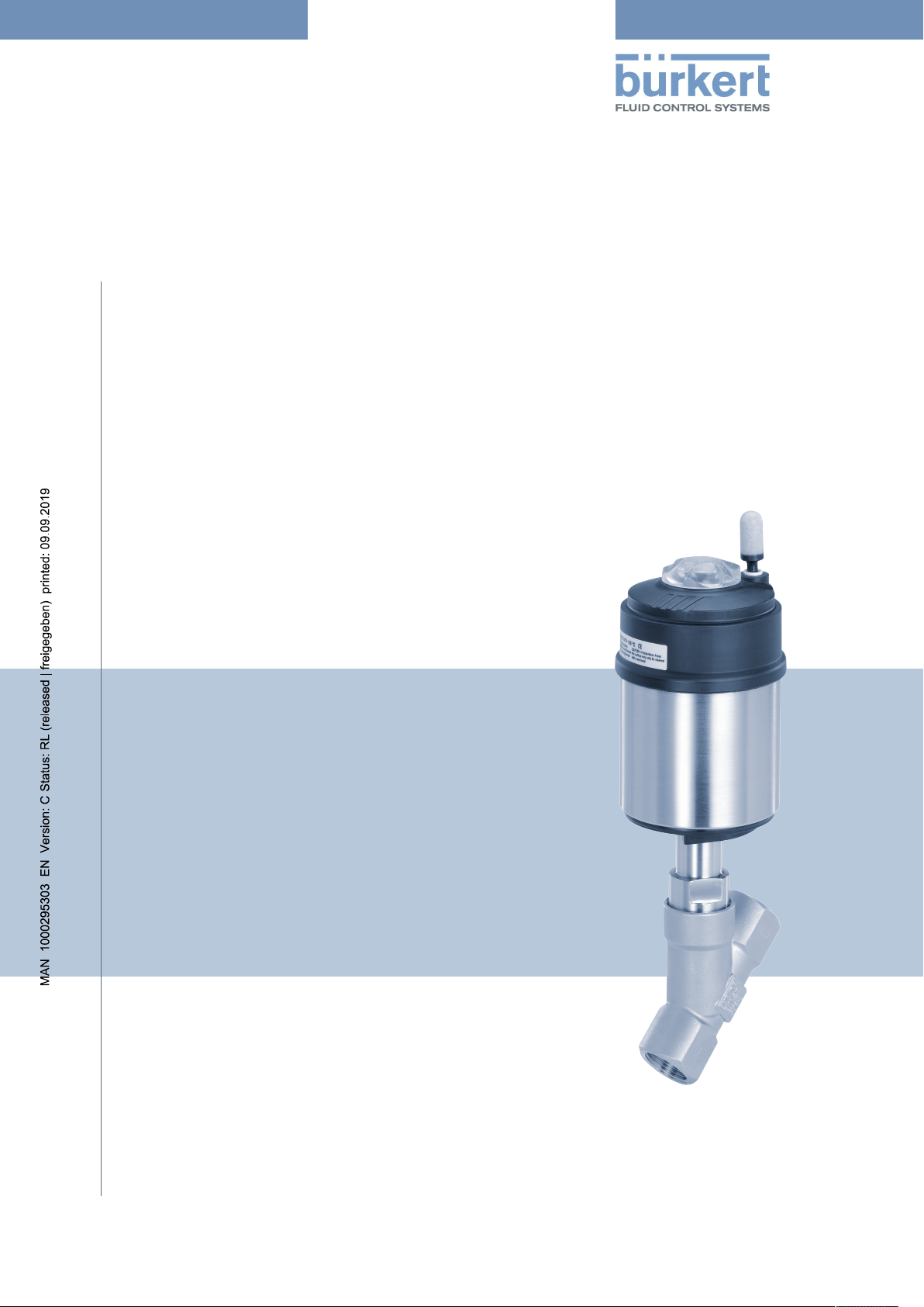
Type 2100
2/2 and 2/3-way angle seat valve
Operating Instructions
Page 2
We reserve the right to make technical changes without notice.
© Bürkert Werke GmbH & Co. KG, 2008 - 2019
Operating Instructions 1903/10_EUml 00805596 / Original DE
Page 3
Type 2100
Contents
CONTENTS
1 About these instructions ............................................................................................................................5
1.1 Symbols............................................................................................................................................ 5
1.2 Definition of terms ............................................................................................................................ 5
2 Intended use ...............................................................................................................................................7
3 Basic safety instructions............................................................................................................................8
4 General information..................................................................................................................................10
4.1 Contact address ............................................................................................................................. 10
4.2 Warranty ......................................................................................................................................... 10
4.3 Information on the Internet ............................................................................................................. 10
5 Product description..................................................................................................................................11
5.1 Features.......................................................................................................................................... 11
5.2 Structure and function.................................................................................................................... 11
5.2.1 Control functions ...............................................................................................................12
5.2.2 Flow direction below seat ..................................................................................................13
5.2.3 Flow direction above the seat............................................................................................13
5.3 Variant 3-position actuator ............................................................................................................. 13
5.3.1 Control function variant 3-position actuator ...................................................................... 14
5.4 Device options................................................................................................................................ 14
5.5 Variants........................................................................................................................................... 15
6 Technical data ..........................................................................................................................................16
6.1 Conformity ...................................................................................................................................... 16
6.2 Standards ....................................................................................................................................... 16
6.3 Type label ....................................................................................................................................... 16
6.3.1 Designation of the actuator size ........................................................................................16
6.4 Operating conditions ...................................................................................................................... 17
6.4.1 Temperature ranges...........................................................................................................17
6.4.2 Pressure ranges 2/2-way valve..........................................................................................17
6.4.3 Pressure ranges 2/3-way valve..........................................................................................21
6.5 Flow values and characteristics 2/3-way valve .............................................................................. 22
6.6 Mechanical data ............................................................................................................................. 28
7 Installation ................................................................................................................................................29
7.1 Safety instructions installation........................................................................................................ 29
7.2 Preparatory work ............................................................................................................................ 30
7.2.1 Attach dirt trap ...................................................................................................................30
7.3 Installing valve body ....................................................................................................................... 30
7.4 Installing devices with welded connection ..................................................................................... 30
7.4.1 Removing actuator from the valve body for devices without control unit .........................30
7.4.2 Removing actuator from the valve body for devices with installed control unit ................31
7.4.3 Installing actuator on valve body .......................................................................................31
7.5 Installing control unit ...................................................................................................................... 32
3
Page 4
Type 2100
Contents
7.6 Turning actuator ............................................................................................................................. 32
7.6.1 Turning the actuator, devices with hexagon nut................................................................32
7.6.2 Turning actuator, devices without hexagon head..............................................................33
7.7 Connecting device pneumatically .................................................................................................. 35
7.7.1 Connecting control medium ..............................................................................................35
8 Start-up .....................................................................................................................................................37
8.1 Set middle position on 3-position actuator .................................................................................... 37
9 Deinstallation ............................................................................................................................................39
10 Maintenance .............................................................................................................................................40
10.1 Safety instructions maintenance .................................................................................................... 40
10.2 Maintenance work .......................................................................................................................... 40
10.2.1 Actuator .............................................................................................................................40
10.2.2 Wearing parts.....................................................................................................................40
10.2.3 Visual inspection ................................................................................................................41
10.2.4 Cleaning .............................................................................................................................41
10.3 Changing the valve set ................................................................................................................... 41
10.3.1 Removing actuator from the valve body for devices without control unit ......................... 42
10.3.2 Changing the valve set ......................................................................................................43
10.3.3 Installing actuator on valve body .......................................................................................43
10.4 Changing the packing gland........................................................................................................... 44
10.4.1 Removing actuator from the valve body for devices without control unit ......................... 45
10.4.2 Removing swivel plate ....................................................................................................... 45
10.4.3 Changing packing gland ....................................................................................................46
10.4.4 Installing swivel plate .........................................................................................................48
10.4.5 Installing actuator on valve body .......................................................................................48
11 Faults ........................................................................................................................................................50
12 Replacement parts, accessories .............................................................................................................51
12.1 Replacement part set ..................................................................................................................... 51
12.2 Installation tools.............................................................................................................................. 52
13 Transportation, storage, disposal............................................................................................................53
4
Page 5
Type 2100
About these instructions
1 ABOUT THESE INSTRUCTIONS
The operating instructions describe the entire life cycle of the device.
Keep these instructions ready to hand at the operation site.
Important safety information.
▶ Carefully read these instructions.
▶ Observe in particular the safety instructions, intended use and operating conditions.
▶ Persons, who work on the device, must read and understand these instructions.
1.1 Symbols
DANGER!
Warns of an immediate danger.
▶ Failure to observe the warning will result in fatal or serious injuries.
WARNING!
Warns of a potentially dangerous situation.
▶ Failure to observe the warning may result in serious or fatal injuries.
CAUTION!
Warns of a possible danger.
▶ Failure to observe the warning may result in moderate or minor injuries.
ATTENTION!
Warns of damage to property.
▶ Failure to observe the warning may result in damage to the device or system.
Indicates important additional information, tips and recommendations.
Refers to information in these instructions or in other documentation.
Designates an instruction for risk prevention.
Designates a procedure which you must carry out.
Indicates a result.
1.2 Definition of terms
In these instructions the term "device" denotes the following device types:
Angle seat valve Type 2100
The abbreviation “Ex” used in these instructions always stands for “potentially explosive atmosphere”.
5
Page 6

Type 2100
About these instructions
The term “büS” (Bürkert system bus) used in this manual refers to the communication bus developed by
Bürkert, based on the CANopen protocol.
6
Page 7
Type 2100
Intended use
2 INTENDED USE
The angle seat valve Type 2100 is designed to control the flow rate of media. The permitted media are listed in the "Technical data [}16]".
▶ Use the device for its intended purpose only. Non-intended use of the device may be dangerous to
people, nearby equipment and the environment.
▶ Correct transportation, correct storage as well as correct installation, commissioning, operation and
maintenance are essential for reliable and problem-free operation.
▶ When using the device, observe the permitted data, operating conditions and application conditions.
This information can be found in the contractual documents, the operating instructions and on the type
label.
▶ Use the device only in conjunction with third-party devices and components recommended and author-
ized by Bürkert.
▶ In potentially explosive atmospheres, only use devices approved for use in those areas. These devices
are labeled with a separate Ex type label. For such use, note the information provided on the separate
Ex type label and the additional explosion-related information or separate explosion-related operating instructions.
▶ Protect device from environmental influences (e.g. radiation, air humidity, fumes). If you have any ques-
tions, contact your Bürkert sales department.
7
Page 8
Type 2100
Basic safety instructions
3 BASIC SAFETY INSTRUCTIONS
These safety instructions do not take into account any unforeseen circumstances and events which occur
during installation, operation and maintenance.
The operator is responsible for observing the location-specific safety regulations, also with reference to the
personnel.
DANGER!
Risk of injury from high pressure and discharge of medium.
▶ Before working on the device or system, switch off the pressure. Vent or drain lines.
DANGER!
Electric shock due to installed electrical component.
▶ Before working on the device or system, switch off the power supply. Secure against reactivation.
▶ Observe the applicable accident prevention and safety regulations for electrical devices.
WARNING!
Risk of injury when opening the actuator.
The actuator contains a spring under tension. When the actuator is opened, the spring will jump out and
may cause injuries.
▶ Do not open the actuator.
WARNING!
Risk of injury due to moving parts.
▶ Do not reach into openings in the device.
▶ Operate 3-position actuator with transparent cap only.
WARNING!
Danger of burns and risk of fire.
Quickly switching actuators or hot medium may cause the surface of the device to become hot.
▶ Only touch the device while wearing protective gloves.
▶ Keep the device away from highly flammable substances and media.
WARNING!
Danger due to loud noises.
Depending on the usage conditions, the device may generate loud noises. Detailed information on the
probability of loud noises is available from the respective sales department.
▶ Wear hearing protection when in the vicinity of the device.
WARNING!
Discharge of medium if packing gland worn.
▶ If media are hazardous, safeguard the environment around the discharge point.
8
Page 9
Type 2100
Basic safety instructions
To prevent injuries, observe the following:
▶ Secure device or plant to prevent unintentional activation.
▶ Only trained technicians may perform installation and maintenance work.
▶ Perform installation and maintenance with suitable tools only.
▶ Transport, install and remove heavy device only with the aid of a second person and using suitable tools.
▶ Following interruption of the process, ensure that the process is restarted in a controlled manner.
Observe sequence:
1. Apply electrical or pneumatic supply.
2. Charge with medium.
▶ Do not make any changes to the device and do not subject it to mechanical stress.
▶ Feed only those media, which are listed in the chapter "Technical data", into the medium ports.
▶ Operate the device only in perfect state and in consideration of the operating instructions.
▶ For applications planning and operation of the device, observe the plant-specific safety regulations.
▶ Observe the general rules of technology.
▶ The plant owner is responsible for the safe operation and handling of the plant.
To protect the environment, observe the following:
▶ The pilot exhaust air of the device may be contaminated by lubricants.
9
Page 10
4 GENERAL INFORMATION
4.1 Contact address
Germany
Bürkert Fluid Control Systems
Sales Center
Christian-Bürkert-Str. 13−17
D-74653 Ingelfingen
Phone: + 49 (0) 7940 - 10 91 111
Fax: + 49 (0) 7940 - 10 91 448
E-mail: info@burkert.com
Type 2100
General information
International
The contact addresses can be found on the back pages of the printed Quickstart. Also on the Internet at:
http://www.burkert.com
4.2 Warranty
A precondition for the warranty is that the device is used as intended in consideration of the specified usage conditions.
4.3 Information on the Internet
Operating instructions and data sheets for the Bürkert products can be found on the Internet at:
https://www.burkert.com/en
10
Page 11

Type 2100
Product description
5 PRODUCT DESCRIPTION
The device is specially optimised for decentralised process automation and meets all the relevant requirements, even under difficult usage conditions.
Its design enables the easy integration of automation modules in all extension stages, whether they are
electrical/optical position feedback, pneumatic control units, or even an integrated fieldbus interface. Long
service life and high tightness are achieved by the tried and tested self-adjusting packing gland. The system, consisting of valve and automation module is distinguished by a compact and sleek design, integrated
pilot air ducts, a high chemical resistance, the degrees of protection IP65 or IP67 as well as the NEMA protection class 4X.
The device uses neutral gases or air to control the flow rate of liquid or gaseous media, such as water, alcohol, oil, fuel, saline solution, lye, organic solvent or vapour.
5.1 Features
▪ Body made of stainless steel with threaded connection, clamp connection or welded connection
▪ Easy integration of automation modules
▪ Actuator can be rotated steplessly by 360°
▪ High chemical resistance
▪ High flow values through flow rate-optimised valve body made of stainless steel
▪ High seat tightness by swivel plate
▪ Integrated pilot air duct in combination with a Bürkert automation module
▪ High tightness and long service life due to self-adjusting packing gland
▪ Maintenance-free under normal conditions
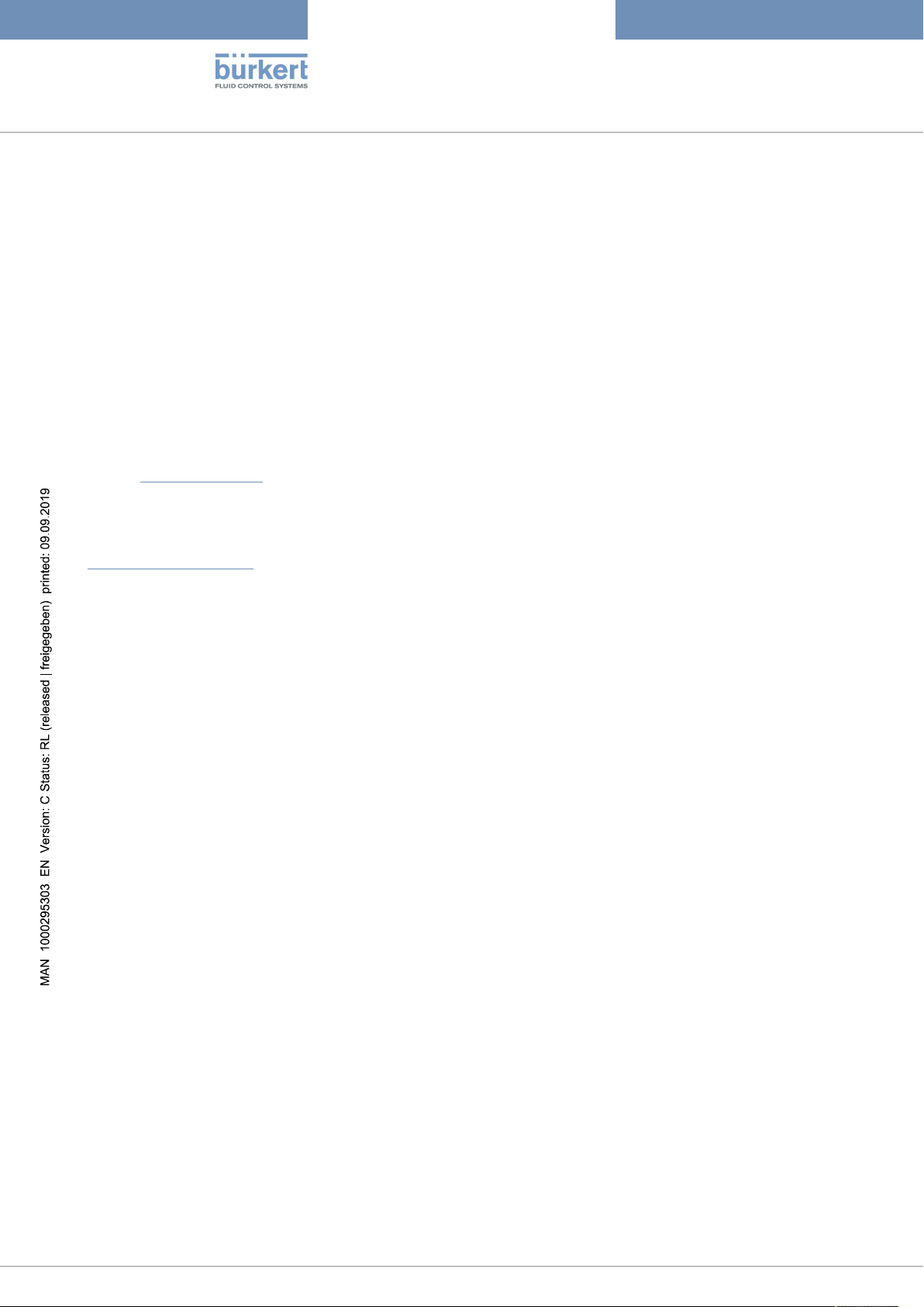
5.2 Structure and function
The device consists of a pneumatically actuated piston actuator and a 2-way valve body. The actuator is
manufactured from polyphenylene sulphide (PPS). Valve body and actuator housing made of stainless steel.
Spring force or pneumatic pilot pressure generate the closing force on the swivel plate. The closing force is
transferred by a spindle connected to the actuator piston.
11
Page 12
Type 2100
Exhaust port for CFA, CFB
Pilot air port for CFI
(with collet)
2
Pilot air port
for CFA, CFB, CFI
(with collet)
Body connection
with wrench flat
1
Digits for indicating the flow
direction
Transparent cap with position
indicator
Actuator cover
Actuator housing
Angle seat body
Port connection
2 (A),(P)
1 (P),(A)
up
down
2 (B),(P)
1 (P),(B)
up
down
2(A),(P)
1(P),(A)
up
down
Product description
Fig.1: Structure and description of the device
5.2.1 Control functions
Control function Definition Circuit symbol Figure
A (CFA) Closed by spring force in
rest position.
B (CFB) Opened by spring force
in rest position.
I (CFI) Actuating function via re-
ciprocal pressurisation.
Tab.1: Control functions
12
Page 13
Type 2100
CFA /
CFI
CFB /
CFI
Product description
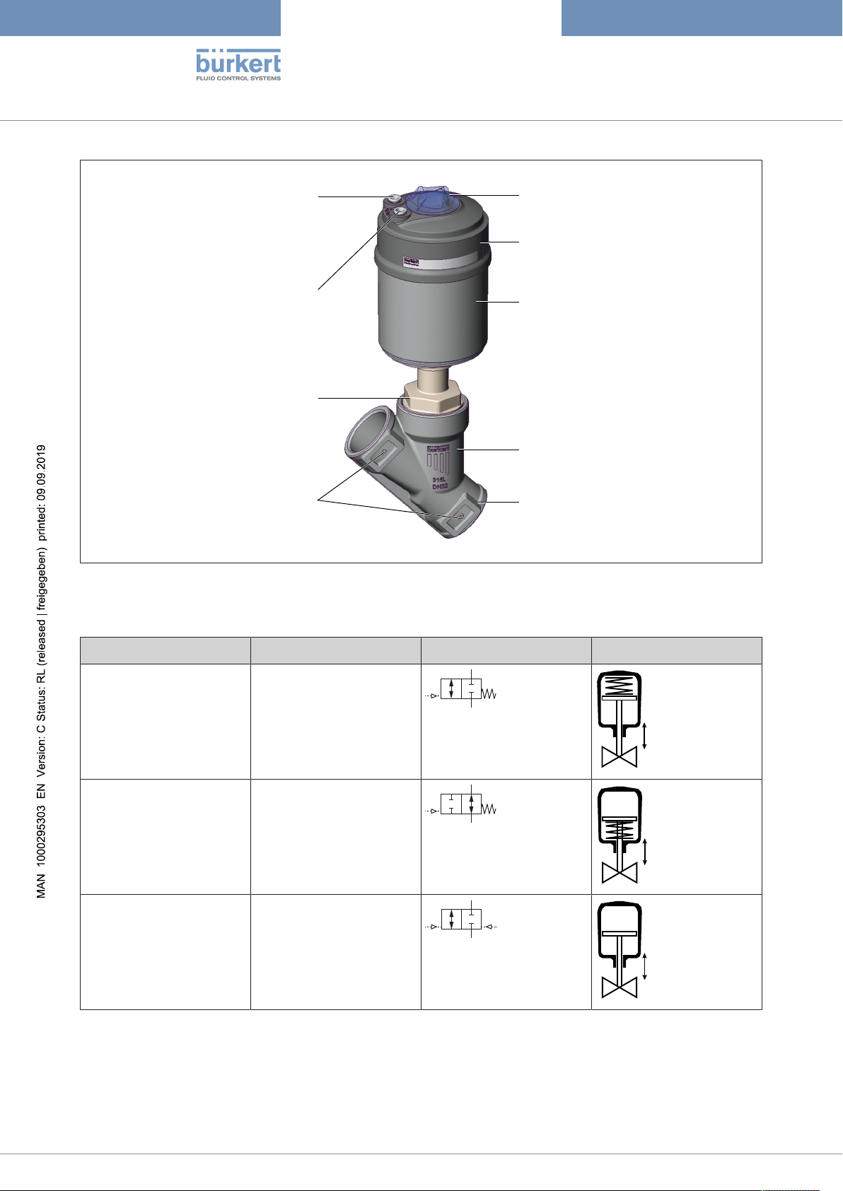
5.2.2 Flow direction below seat
WARNING!
Valve seat leaking when control pressure is too low or medium pressure is too high.
If control pressure is too low for control function B and control function I or medium pressure is too high,
the valve seat may leak.
▶ Observe values for minimum control pressure and maximum medium pressure.
Depending on the control function, the valve closes by spring force (control function A) or pilot pressure
(control function B and I) against the medium flow.
As the medium is present under the swivel plate, the medium pressure contributes to the opening of the
valve.
Fig.2: Flow direction below seat, valve closes against medium flow
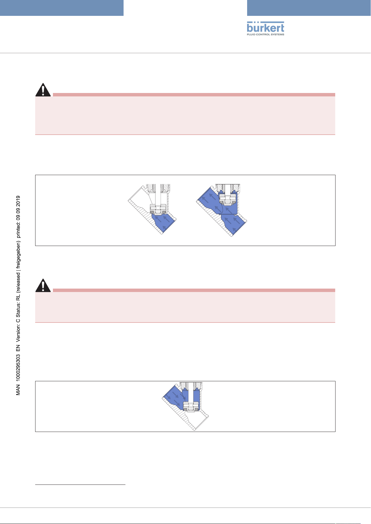
5.2.3 Flow direction above the seat
DANGER!
Risk of injury from rupturing lines and device when flow direction above the seat.
A pressure surge of liquid media may cause the lines and device to rupture.
▶ Do not use valves with flow direction above the seat for liquid media.
Flow direction above the seat is possible only on valves with control function A (closed by spring force in
rest position)1.
The valve closes by spring force with the medium flow. As the medium is present above the swivel plate,
the medium pressure contributes to the closing of the valve. The medium pressure also supports the sealing of the valve seat.
The valve opens by the pilot pressure.
Fig.3: Flow direction above the seat, valve closes with medium flow
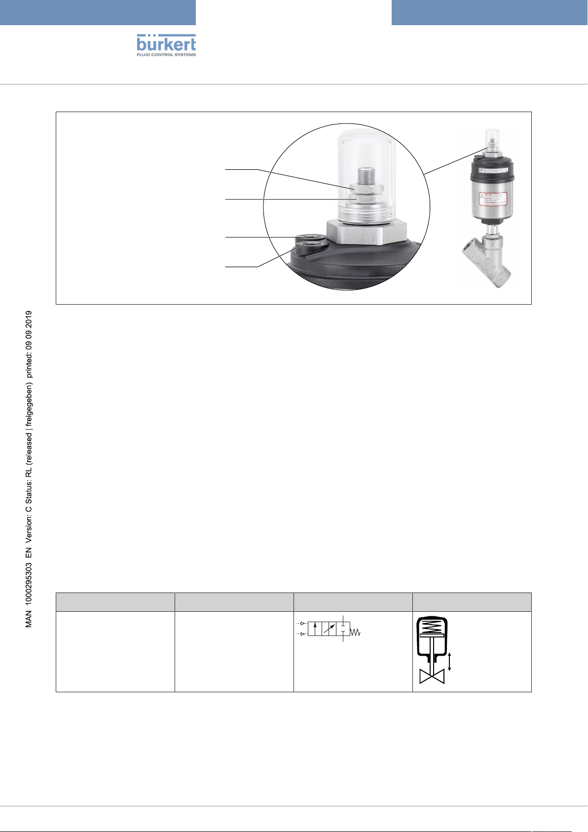
5.3 Variant 3-position actuator
With the 3-position actuator the valve can have a middle position. This variant is available only in control
function A (closed by spring force in rest position).
1
Not for seat size 80
13
Page 14
Type 2100
Pilot air port 1
Nut for setting the middle position
Lock nut
Pilot air port 2
2 (A)
1 (P)
up
down
Product description
Fig.4: Variant 3-position actuator
The closing force on the swivel plate is transferred by a spindle. The spindle is connected to the actuator
piston.
Middle position
The middle position corresponds to a specific, adjustable flow rate of the medium. It is reached by an additional piston in the upper part of the actuator. The middle position is set with a nut (see figure).
The additional piston is used as a stop for the actuator piston. If pilot air port 2 is pressurised, the additional
piston moves downwards to the set position. If pilot air port 1 is then pressurised, the actuator piston
moves upwards until it hits the additional piston and stops.
Maximum stroke
If the upper air chamber is vented by pilot air port 2, both pistons move upwards. As a result, the maximum
stroke is reached.
Closing the valve
If the lower air chamber is vented by pilot air port 1, the spring force acts on the actuator piston. The spring
force moves the actuator piston downwards until the valve is closed (rest position).
5.3.1 Control function variant 3-position actuator
Control function Definition Circuit symbol Figure
A (CFA) Closed by spring force in
rest position.
Tab.2: Control functions
The inflow (2->1; 1->2) depends on the flow direction.
5.4 Device options
14
▪ Stroke limit
Page 15
Type 2100
Product description
Limiting the maximum or minimum flow rate volume with an adjusting screw.
▪ Position feedback sensors and control units
Different variants are available depending on the requirement.
5.5 Variants
Information on the variants of the device can be found in the data sheet at https://www.burkert.com/en or in your sales department.
15
Page 16
Type 2100
2100 A 32M PTFE VA
Pilot 4.8-10bar
Tmed -10°C - +185°C
Flow 1
Pmed 8.5 bar
2 Da=42.4 s=2.0 Kv 27 W31MS
00188096
Identification for food contact
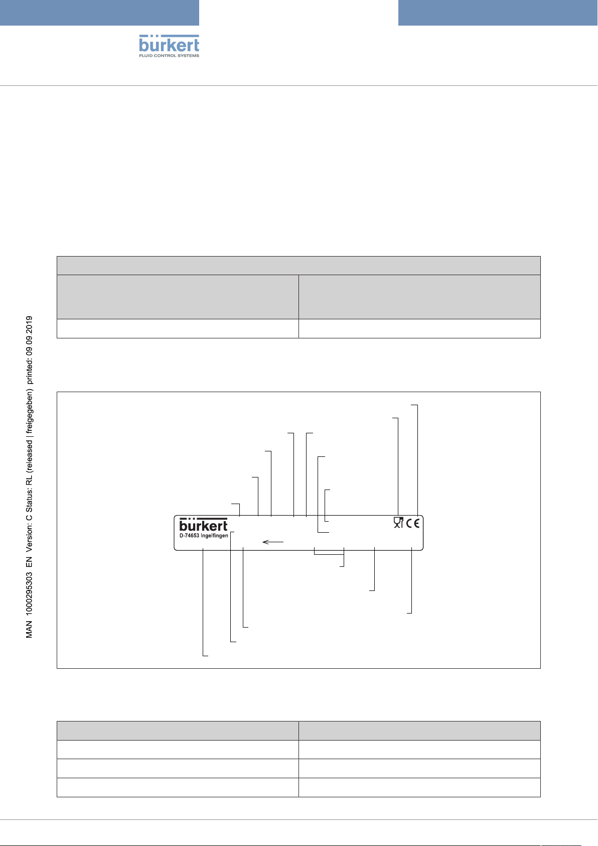
Type
Control function
Nominal diameter /
actuator size
Manufacture code
CE label
Permitted pilot
pressure
Permitted
medium
pressure
Body material
Seal material
Dimensions port
connection
Flow capacity
Permitted medium temperature
Flow direction
Order number of the device
Technical data
6 TECHNICAL DATA
6.1 Conformity
The device conforms to the EC directives as per the EC Declaration of Conformity (if applicable).
6.2 Standards
The applied standards, which are used to demonstrate conformity with the directives, are listed in the EU
type examination certificate and/or the EU Declaration of Conformity (if applicable).
According to Pressure Equipment Directive observe the following operating conditions:
Nominal diameter port connection Maximum pressure for compressible fluids of Group
1 (dangerous gases and vapours according to Art.
3, No. 1.3, letter a, first dash)
DN65 15 bar
Tab.3: Maximum pressure for compressible fluids of Group 1
6.3 Type label
Fig.5: Example of a type label
16
6.3.1 Designation of the actuator size
Actuator size [mm] Designation
ø50 D
ø70 M
ø90 N
Page 17

Type 2100
Technical data
Actuator size [mm] Designation
ø130 P
Tab.4: Designation of the actuator size
6.4 Operating conditions
Degree of protection IP67 according to IEC 529 / DIN EN 60529
Flow media Water, alcohols, oils, fuels, hydraulic fluids, saline solutions,
lyes, organic solvents, vapour, air, neutral gases
Control media Neutral gases, air
Sound pressure level <70dB(A)
The sound pressure level may be higher depending on the usage conditions
6.4.1 Temperature ranges
Medium
Actuator size [mm] Actuator material Medium temperature (for
PTFE seal) [°C]
2
Ambient temperature
[°C]
ø 50 PPS −10...+185 0...+60
ø 70
0...+100
ø 90
ø 130
Tab.5: Temperature range of medium
Environment
Pilot air port Ambient temperature [°C]
6
Push-in connector –10...+60
Threaded bushing –10...+100
Tab.6: Temperature range of environment
6.4.2 Pressure ranges 2/2-way valve
Maximum pilot pressure
3
4
5
Actuator size [mm] Maximum pilot pressure [bar]
ø50 10
2
For applications at Tmax > 130 °C a PEEK seal is recommended.
3
When using a pilot valve the maximum ambient temperature is +55 °C
4
Pilot air connector as push-in connector.
5
Control air connector as threaded bushing.
6
When using an attachment part, observe its temperature range.
17
Page 18

Type 2100
Technical data
Actuator size [mm] Maximum pilot pressure [bar]
ø70 10
7
ø90 10
ø130 7
Tab.7: Maximum pilot pressure
Medium pressure and pilot pressure for control function A, flow direction below seat (standard)
Seat size Maximum medium pressure [bar] Minimum pilot pressure [bar]
Actuator size [mm] Actuator size [mm]
ø50 ø70 ø90 ø130 ø50 ø70 ø90 ø130
15 25 25 - - 5.2 4.8 - -
20 16 20
25 9 16
32 - 8.5 16 - - 4.8 5 -
40 6 16
50 - 4 10 16 - 4.8 5 5
65 - 5 16 (158) - 5 5.6
80 - - - 10 - - - 5.6
Tab.8: Medium pressure and pilot pressure, control functionA, standard
Medium pressure and pilot pressure for control function A, flow direction below seat, reduced spring
force (EC04)
Seat size Maximum medium pressure [bar] Minimum pilot pressure [bar]
Actuator size [mm] Actuator size [mm]
ø50 ø70 ø90 ø130 ø50 ø70 ø90 ø130
15 14 16 - - 3.2 2.5 - -
20 6 12
25 3 6
32 - 3.5 9 - - 2.5 2.5 -
18
40 2 6 16 2.5
50 - - 3.5 11 - - 2.5 2.5
65 - 7.5 - - 3.2
Tab.9: Medium pressure and pilot pressure, control function A, reduced spring force (EC04)
7
The maximum permitted pilot pressure is limited to 7 bar for the following device variant: Actuator size ø70, seat size
50, flow direction above the seat
8
According to Pressure Equipment Directive for compressible fluids of Group 1 (dangerous gases and vapours accord-
ing to Art. 3, No. 1.3, letter a, first dash)
Page 19

Type 2100
16
12
14
0
0
2
4
6
8
10
1 98765432 10
Medium pressure [bar]
Pilot pressure [bar]
ø50
CFA
DN25
DN20
DN15
16
12
14
0
0
2
4
6
8
10
1 98765432 10
Medium pressure [bar]
Pilot pressure [bar]
ø70
CFA
DN32
DN20
DN40
DN50
DN25
DN15
16
12
14
0
0
2
4
6
8
10
1 98765432 10
Medium pressure [bar]
Pilot pressure [bar]
ø90
CFA
DN40
DN65
DN50
Technical data
Required minimum control pressure depending on the medium pressure
In the following graphs the required minimum control pressure is shown for the respective control function
depending on the medium pressure.
Control function A (CFA), flow direction above the seat
Fig.6: Actuator ø50 mm, CFA, flow direction above the seat
Fig.7: Actuator ø70 mm, CFA, flow direction above the seat
Fig.8: Actuator ø90 mm, CFA, flow direction above the seat
19
Page 20

Control function B and I, flow direction below seat
16
12
14
0
0
2
4
6
8
10
1 98765432 10
Medium pressure [bar]
Pilot pressure [bar]
ø50
CFB/CFI
DN25
DN20
DN15
16
12
14
0
0
2
4
6
8
10
1 98765432 10
Medium pressure [bar]
Pilot pressure [bar]
ø70
CFB/CFI
DN25
DN20
DN40
DN50
DN32
DN15
16
12
14
0
0
2
4
6
8
10
1 98765432 10
Medium pressure [bar]
Pilot pressure [bar]
ø90
CFB/CFI
DN40
DN50
DN65
DN32
16
12
14
0
0
2
4
6
8
10
1 98765432 10
Medium pressure [bar]
Pilot pressure [bar]
ø130
CFB/CFI
DN40
DN50
DN65
DN80
Fig.9: Actuator ø50 mm, CFB and CFI, flow direction below seat
Type 2100
Technical data
20
Fig.10: Actuator ø70 mm, CFB and CFI, flow direction below seat
Fig.11: Actuator ø90 mm, CFB and CFI, flow direction below seat
Fig.12: Actuator ø130 mm, CFB and CFI, flow direction below seat
Page 21

Type 2100
16
12
14
0
0
2
4
6
8
10
642
Medium pressure [bar]
Pilot pressure [bar]
ø50
CFA
DN15
DN25
DN20
Technical data
6.4.3 Pressure ranges 2/3-way valve
Maximum pilot pressure
Actuator size [mm] Maximum pilot pressure [bar]
ø50 7
ø70
ø90
Tab.10: Maximum pilot pressure
Medium pressure and pilot pressure for control function A, flow direction below seat (standard)
Seat size Maximum medium pressure [bar] Minimum pilot pressure [bar]
Actuator size [mm] Actuator size [mm]
ø50 ø70 ø90 ø50 ø70 ø90
15 16 16 - 5 5 -
20 10 16
25 5 12
32 - 8.5 16 - 5 5
40 5 12
50 - - 7 - - 5
Tab.11: Medium pressure and pilot pressure, control functionA, standard
Variants with lower pilot pressure (reduced spring force) are available on request. Contact your
Bürkert sales department or the Bürkert Sales Center (info@burkert.com
).
Required minimum control pressure depending on the medium pressure
In the following graphs the required minimum control pressure is shown for control function A depending on
the medium pressure.
Fig.13: Actuator ø50 mm, control function A, flow direction above the seat
21
Page 22

16
12
14
0
0
2
4
6
8
10
642
Medium pressure [bar]
Pilot pressure [bar]
ø70
CFA
DN15
DN25
DN20
DN32
DN40
Fig.14: Actuator ø70 mm, control function A, flow direction above the seat
16
12
14
0
0
2
4
6
8
10
642
Medium pressure [bar]
Pilot pressure [bar]
ø90
CFA
DN32
DN50
DN40
Type 2100
Technical data
Fig.15: Actuator ø90 mm, control function A, flow direction above the seat
6.5 Flow values and characteristics 2/3-way valve
Seat size 15
Stroke [%] Flow coefficient [m3/h] Stroke [%] Flow coefficient [m3/h]
0 0 60 4.25
10 1.75 70 4.50
20 2.50 80 4.65
30 3.10 90 4.80
40 3.60 100 5.00
50 4.00
Tab.12: Flow values seat size 15, actuator size D (ø50)
22
Page 23

Type 2100
5
4.5
4
3.5
3
2.5
2
1.5
1
0.5
0
0 20 40 60 80 100
Stroke [%]
Flow coefficient [m³/h]
5
4.5
4
3.5
3
2.5
2
1.5
1
0.5
0
0 20 40 60 80 100
Stroke [%]
Flow coefficient [m³/h]
Technical data
Fig.16: Flow characteristics seat size 15, actuator size D (ø50)
Stroke [%] Flow coefficient [m3/h] Stroke [%] Flow coefficient [m3/h]
0 0 60 3.80
10 1.00 70 4.10
20 1.80 80 4.50
30 2.50 90 4.80
40 3.00 100 5.00
50 3.40
Tab.13: Flow values seat size 15, actuator size M (ø70)
Fig.17: Flow characteristics seat size 15, actuator size M (ø70)
Seat size 20
Stroke [%] Flow coefficient [m3/h] Stroke [%] Flow coefficient [m3/h]
0 0 60 8.30
10 2.60 70 8.80
20 4.50 80 9.20
30 5.80 90 9.60
40 6.80 100 10.00
50 7.70
Tab.14: Flow values seat size 20, actuator size D (ø50)
23
Page 24

Type 2100
10
9
8
7
6
5
4
3
2
1
0
0 20 40 60 80 100
Stroke [%]
Flow coefficient [m³/h]
12
10
0
0 20 40 60 80 100
Stroke [%]
Flow coefficient [m³/h]
8
6
4
2
Technical data
Fig.18: Flow characteristics seat size 20, actuator size D (ø50)
Stroke [%] Flow coefficient [m3/h] Stroke [%] Flow coefficient [m3/h]
0 0 60 8.90
10 1.50 70 9.40
20 4.30 80 10.00
30 6.40 90 10.60
40 7.50 100 11.00
50 8.20
Tab.15: Flow values seat size 20, actuator size M (ø70)
Fig.19: Flow characteristics seat size 20, actuator size M (ø70)
Seat size 25
Stroke [%] Flow coefficient [m3/h] Stroke [%] Flow coefficient [m3/h]
0 0 60 12.20
10 3.00 70 13.10
20 5.80 80 13.80
30 7.90 90 14.40
40 9.90 100 15.00
50 11.10
Tab.16: Flow values seat size 25, actuator size D (ø50)
24
Page 25

Type 2100
16
0
0 20 40 60 80 100
Stroke [%]
Flow coefficient [m³/h]
14
12
10
8
6
4
2
18
0
0 20 40 60 80 100
Stroke [%]
Flow coefficient [m³/h]
8
10
12
14
16
2
6
4
Technical data
Fig.20: Flow characteristics seat size 25, actuator size D (ø50)
Stroke [%] Flow coefficient [m3/h] Stroke [%] Flow coefficient [m3/h]
0 0 60 13.50
10 1.50 70 14.80
20 4.40 80 15.70
30 7.80 90 16.50
40 10.30 100 18.00
50 12.10
Tab.17: Flow values seat size 25, actuator size M (ø70)
Fig.21: Flow characteristics seat size 25, actuator size M (ø70)
Seat size 32
Stroke [%] Flow coefficient [m3/h] Stroke [%] Flow coefficient [m3/h]
0 0 60 19.70
10 5.20 70 21.80
20 9.40 80 23.70
30 12.50 90 25.00
40 15.00 100 26.00
50 17.40
Tab.18: Flow values seat size 32, actuator size M (ø70)
25
Page 26

Type 2100
28
0
0 20 40 60 80 100
Stroke [%]
Flow coefficient [m³/h]
8
12
16
20
24
4
28
0
0 20 40 60 80 100
Stroke [%]
Flow coefficient [m³/h]
8
12
16
20
24
4
Technical data
Fig.22: Flow characteristics seat size 32, actuator size M (ø70)
Stroke [%] Flow coefficient [m3/h] Stroke [%] Flow coefficient [m3/h]
0 0 60 21.00
10 5.40 70 23.10
20 10.10 80 24.80
30 13.20 90 26.10
40 16.20 100 27.00
50 18.70
Tab.19: Flow values seat size 32, actuator size N (ø90)
Fig.23: Flow characteristics seat size 32, actuator size N (ø90)
Seat size 40
Stroke [%] Flow coefficient [m3/h] Stroke [%] Flow coefficient [m3/h]
0 0 60 25.40
10 5.50 70 28.30
20 10.50 80 31.10
30 14.90 90 33.80
40 18.80 100 36.00
50 22.30
Tab.20: Flow values seat size 40, actuator size M (ø70)
26
Page 27

Type 2100
40
0
0 20 40 60 80 100
Stroke [%]
Flow coefficient [m³/h]
10
15
20
25
30
35
5
40
0
0 20 40 60 80 100
Stroke [%]
Flow coefficient [m³/h]
10
15
20
25
30
35
5
Technical data
Fig.24: Flow characteristics seat size 40, actuator size M (ø70)
Stroke [%] Flow coefficient [m3/h] Stroke [%] Flow coefficient [m3/h]
0 0 60 27.30
10 6.20 70 30.60
20 11.60 80 33.60
30 16.10 90 36.30
40 20.00 100 38.00
50 23.70
Tab.21: Flow values seat size 40, actuator size N (ø90)
Fig.25: Flow characteristics seat size 40, actuator size N (ø90)
Seat size 50
Stroke [%] Flow coefficient [m3/h] Stroke [%] Flow coefficient [m3/h]
0 0 60 32.10
10 8.10 70 35.90
20 13.50 80 40.20
30 18.60 90 44.70
40 23.00 100 49.00
50 28.00
Tab.22: Flow values seat size 50, actuator size N (ø90)
27
Page 28

50
0
0 20 40 60 80 100
Stroke [%]
Flow coefficient [m³/h]
5
10
15
20
25
30
35
40
45
Fig.26: Flow characteristics seat size 50, actuator size N (ø90)
6.6 Mechanical data
Actuator size See type label
Type 2100
Technical data
Installation position any, preferably actuator face up
Materials
Valve body 316L
Actuator PPS and stainless steel
Sealing elements FKM and EPDM
Spindle seal (with silicone grease) PTFE V-rings with spring compensation
Spindle 1.4401, 1.4404
Spindle guide PEEK
Seat seal swivel plate PTFE, PEEK
Optional: EPDM, NBR, FKM
Ports
Pilot air port Push-in connector 6/4 mm or threaded connection ¼"
More on request
Port connection G½...G3 (NPT, RC on request)
Welded connection as per ISO 4200, DIN 11850 R2
Others on request
28
Page 29

Type 2100
Installation
7 INSTALLATION
7.1 Safety instructions installation
DANGER!
Risk of injury from high pressure and discharge of medium.
▶ Before working on the device or system, switch off the pressure. Vent or drain lines.
WARNING!
Risk of injury due to improper installation.
▶ Only trained technicians may perform installations.
▶ Perform installations with suitable tools only.
WARNING!
Risk of injury due to unintentional activation of the system and uncontrolled restart.
▶ Secure plant to prevent unintentional activation..
▶ Ensure that the plant starts up in a controlled manner only.
DANGER!
For control function I: Danger due to the control pressure failing.
If the control pressure fails, the valve remains in an undefined position.
▶ For a controlled restart, pressurize the device with control pressure and then connect the medium.
WARNING!
Risk of injury due to moving parts.
▶ Do not reach into openings in the device.
▶ Operate 3-position actuator with transparent cap only.
CAUTION!
Risk of injury from heavy device.
During transportation or installation work, a heavy device may fall down and cause injuries.
▶ Transport, install and remove heavy device with the aid of a second person only.
▶ Use suitable tools.
WARNING!
Valve seat leaking when control pressure is too low or medium pressure is too high.
If control pressure is too low for control function B and control function I or medium pressure is too high,
the valve seat may leak.
▶ Observe values for minimum control pressure and maximum medium pressure.
29
Page 30

Type 2100
Installation
DANGER!
Risk of injury from rupturing lines and device when flow direction above the seat.
A pressure surge of liquid media may cause the lines and device to rupture.
▶ Do not use valves with flow direction above the seat for liquid media.
7.2 Preparatory work
Observe flow direction on the type label.
Remove soiling from pipelines.
Ensure that pipelines are in alignment.
7.2.1 Attach dirt trap
Dirt trap for devices with approval according to DIN EN 161
According to DIN EN 161 "Automatic shut-off valves for gas burners and gas appliances", a dirt trap, which
prevents the penetration of a 1 mm test pin, must be installed upstream of the valve.
Attach dirt trap upstream of the valve.
7.3 Installing valve body
Connect valve body to pipeline.
Devices with welded connection: Weld valve body into pipeline. To do this, observe chapter "Installing
devices with welded connection".
7.4 Installing devices with welded connection
ATTENTION!
Damage to the actuator when welding the valve body into the pipeline.
▶ Before welding into the pipeline, remove the actuator.
7.4.1 Removing actuator from the valve body for devices without control unit
Clamp valve body into a holding device.
Devices with collet
30
ATTENTION!
Damage to the valve seat seal or seat contour.
▶ When removing the actuator, the valve must be in the open position.
For control function A pressurise the pilot air port 1 with compressed air (5 bar). Valve opens.
Place a suitable open-end wrench on the wrench flat of the body connection.
Unscrew actuator from the valve body.
Page 31

Type 2100
Seal
Installation
Devices without collet
For control function A: Install control unit. To do this, follow the operating instructions for the control
unit.
ATTENTION!
Damage to the valve seat seal or seat contour.
▶ When removing the actuator, the valve must be in the open position.
For control function A pressurise the pilot air port 1 with compressed air (5 bar). Valve opens.
For control function A with pilot valve: Manually switch device with pilot valve. To do this, follow the operating instructions for the control unit. Valve opens.
Place a suitable open-end wrench on the wrench flat of the body connection.
Unscrew actuator from the valve body.
7.4.2 Removing actuator from the valve body for devices with installed control unit
Clamp valve body into a holding device.
ATTENTION!
Damage to the valve seat seal or seat contour.
▶ When removing the actuator, the valve must be in the open position.
For control function A pressurise the pilot air port 1 with compressed air (5 bar). Valve opens.
For control function A with pilot valve: Manually switch device with pilot valve. To do this, follow the operating instructions for the control unit. Valve opens.
Place a suitable open-end wrench on the wrench flat of the body connection.
Unscrew actuator from the valve body.
7.4.3 Installing actuator on valve body
Fig.27: Seal
Check seal and replace if required.
31
Page 32

Type 2100
Installation
DANGER!
Danger due to lubricant.
Lubricant may contaminate the medium. There is a risk of explosion in oxygen applications.
▶ For specific applications use only approved lubricants (e.g. for oxygen applications or analysis applica-
tions).
Before re-installation, grease the thread of the body connection (e.g. with Klüberpaste UH1 96-402 from
Klüber).
ATTENTION!
Damage to the valve seat seal or seat contour.
▶ When installing the actuator, the valve must be in the open position.
For control function A pressurise the pilot air port 1 with compressed air (5 bar): Valve opens.
Screw actuator into the valve body. Observe tightening torques of the following table.
Seat size Tightening torque [Nm]
15 45 ±3
20 50 ±3
25 60 ±3
32 65 ±3
40 65 ±3
50 70 ±3
65 100 ±3
80 120 ±5
Tab.23: Tightening torques valve body and body connection
7.5 Installing control unit
Description see chapter "Installation" in the operating instructions for the corresponding control
unit.
7.6 Turning actuator
32
7.6.1 Turning the actuator, devices with hexagon nut
The following description applies only to devices with a hexagon head on the actuator.
For devices without a hexagon head on the actuator: in the operating instructions observe the
chapter "Turning actuator, devices without a hexagon head".
The position of the ports can be steplessly aligned by turning the actuator through 360°.
Page 33

Type 2100
Key contour
Body connection
Actuator
Valve body
Installation
Fig.28: Turn actuator (1)
Clamp valve body in a holding device (only for valves which have not yet been installed).
ATTENTION!
Damage to the seat seal or seat contour.
▶ When turning the actuator, the valve must be in the open position.
For control function A und I9:
pressurise the pilot air port 1 with compressed air. Valve opens.
For devices with control unit and pilot valve: Manually switch device with pilot valve (see operating instructions for the control unit).
Counter with a suitable open-end wrench on the wrench flat of the body connection.
Place a suitable open-end wrench on the hexagon head of the actuator.
DANGER!
Risk of injury from high pressure and discharge of medium.
If the direction of rotation is wrong, the body connection may become detached.
▶ Only turn the actuator is the prescribed direction.
Move the actuator into the required position by turning it counterclockwise (seen from below).
Fig.29: Turn actuator (2)
7.6.2 Turning actuator, devices without hexagon head
The position of the ports can be steplessly aligned by turning the actuator through 360°.
9
If variant available
33
Page 34

Type 2100
Key contour
Body connection
Actuator
Valve body
Installation
Fig.30: Turn actuator (1), devices without hexagon head
Clamp valve body in a holding device (only for valves which have not yet been installed).
ATTENTION!
Damage to the seat seal or seat contour.
▶ When turning the actuator, the valve must be in the open position.
For control function A und I10:
pressurise the pilot air port 1 with compressed air. Valve opens.
Counter with a suitable open-end wrench on the wrench flat of the body connection.
Place special wrench11 in the key contour of the actuator.
DANGER!
Risk of injury from high pressure and discharge of medium.
If the direction of rotation is wrong, the body connection may become detached.
▶ Only turn the actuator is the prescribed direction.
Move the actuator into the required position by turning it clockwise (seen from below).
34
Fig.31: Turn actuator (2), devices without hexagon head
10
11
If variant available
The special wrench (00665702) is available from your Bürkert sales department.
Page 35

Type 2100
Exhaust port CFA, CFB
Pilot air port CFI
Pilot air port CFA, CFB,
CFI
2
1
Installation
7.7 Connecting device pneumatically
DANGER!
Risk of injury due to connection of unsuitable hoses.
▶ Use only hoses which can withstand the pressure and temperature of the medium.
▶ Observe technical data of the hose manufacturer.
DANGER!
For control function I: Danger due to the control pressure failing.
If the control pressure fails, the valve remains in an undefined position.
▶ For a controlled restart, pressurize the device with control pressure and then connect the medium.
For devices with control unit follow the operating instructions for the corresponding control unit.
7.7.1 Connecting control medium
The position of the ports can be steplessly aligned by turning the actuator through 360°. The procedure is described in the chapter "Turning actuator".
Fig.32: Pneumatic ports
Control function A and B:
Connect control medium to pilot air port 1 of the actuator.
Control function A, 3-position actuator:
Connect control medium to pilot air port 1 and 2 of the actuator.
Pressure on pilot air port 1: Valve opens.
Pressure on pilot air port 1 and 2: Valve in middle position.
Control function I:
Connect control medium to pilot air port 1 and 2 of the actuator.
Pressure on pilot air port 1: Valve opens.
Pressure on pilot air port 2: Valve closes.
Silencer
For devices with push-in connection, the silencer to reduce the exhaust air volume is loosely supplied.
Connect the silencer to the free exhaust port 2.
35
Page 36

When operating in an aggressive environment, divert free pneumatic ports into a neutral atmosphere
using a pneumatic hose.
Pilot air hose
Pilot air hoses of sizes 6/4mm or ¼" can be used.
Type 2100
Installation
36
Page 37

Type 2100
Exhaust
H
Transparent
cap
Lock nut
Nut
0 % stroke
100 % stroke
Kv-
Kv+
Position of the nut
Stro
ke
Middle position
Start-up
8 START-UP
WARNING!
Risk of injury from high pressure or hot medium.
Excessively high pressure or temperatures may damage the device and cause leaks.
▶ Observe values for pressure and medium temperature indicated on the type label.
In the case of devices with control unit, observe start-up in the operating instructions for the corresponding control unit.
8.1 Set middle position on 3-position actuator
Open position [100 % stroke]
Pilot air port 1: 5...7 bar
Pilot air port 2: 0 bar
Middle position [0...100 % stroke]
Pilot air port 1: 5...7 bar
Pilot air port 2: 5...7 bar
Fig.33: Setting middle position
Unscrewing transparent cap: Actuator sizes ø50, ø70 and ø90: Width across flats 28.
Pressurise pilot air port 1 of the actuator with compressed air (5 bar).
Loosening lock nut: Actuator size ø50: Width across flats 13; actuator size ø70 and ø90: Width across
flats 17.
Adjust the middle position with the nut.
Retightening lock nut: Actuator size ø50 max. 20+5 Nm; actuator size ø70 max. 30+5 Nm; actuator size
ø90 max. 45+5 Nm.
Screw transparent cap back on.
To limit the middle position to 50 % of the total stroke, set dimension H on the nuts.
37
Page 38

Type 2100
Start-up
Actuator size [mm] Seat size Dimension H ±0.3 [mm] Total stroke [mm]
ø50 15 10.4 10.8
20 8.4 14.8
25 6.4 18.8
ø70 15 12.9 10
20 8.9 18
25 8.9 18
32 8.9 18
40 8.9 18
ø90 32 10.6 20.4
40 10.6 20.4
50 10.6 20.4
Tab.24: Setting the middle position to 50 % of the total stroke
38
Page 39

Type 2100
Deinstallation
9 DEINSTALLATION
DANGER!
Risk of injury from high pressure and discharge of medium.
▶ Before working on the device or system, switch off the pressure. Vent or drain lines.
Loosen pneumatic connection.
Disassemble the device.
39
Page 40

Type 2100
Maintenance
10 MAINTENANCE
10.1 Safety instructions maintenance
DANGER!
Risk of injury from high pressure and discharge of medium.
▶ Before working on the device or system, switch off the pressure. Vent or drain lines.
DANGER!
For control function I: Danger due to the control pressure failing.
If the control pressure fails, the valve remains in an undefined position.
▶ For a controlled restart, pressurize the device with control pressure and then connect the medium.
DANGER!
Risk of injury due to electric shock.
▶ Before working on the device or system, switch off the power supply. Secure against reactivation.
▶ Observe the applicable accident prevention and safety regulations for electrical devices.
WARNING!
Risk of injury due to unintentional activation of the system and uncontrolled restart.
▶ Secure plant to prevent unintentional activation..
▶ Ensure that the plant starts up in a controlled manner only.
WARNING!
Risk of injury due to moving parts.
▶ Do not reach into openings in the device.
▶ Operate 3-position actuator with transparent cap only.
DANGER!
Risk of injury due to improper maintenance.
▶ Only trained technicians may perform maintenance work.
▶ Perform maintenance work using suitable tools only.
40
10.2 Maintenance work
The maintenance work is described in the separate service instructions. These instructions can be found on
our homepage at www.buerkert.de
10.2.1 Actuator
When used in accordance with these operating instructions, the actuator is maintenance-free.
10.2.2 Wearing parts
The following parts are subject to natural wear:
.
Page 41

Type 2100
Relief bore
Maintenance
▪ Seal
▪ Swivel plate with seal
If leaks occur, replace the respective wearing part.
10.2.3 Visual inspection
According to the usage conditions, perform regular visual inspections:
Check medium ports for tightness.
Check relief bore on the pipe for leaks.
Fig.34: Relief bore
10.2.4 Cleaning
Commercially available cleaning agents can be used to clean the outside.
ATTENTION!
Avoid causing damage with cleaning agents.
▶ Before cleaning, check that the cleaning agents are compatible with body materials and seals.
10.3 Changing the valve set
The valve set consists of:
▪ Swivel plate with seal
▪ Pin
▪ Seal
To change the valve set, first remove the actuator from the valve body.
DANGER!
Risk of injury from high pressure and discharge of medium.
▶ Before working on the device or system, switch off the pressure. Vent or drain lines.
DANGER!
Risk of injury due to improper maintenance.
▶ Only trained technicians may perform maintenance work.
▶ Perform maintenance work using suitable tools only.
41
Page 42

Type 2100
Maintenance
10.3.1 Removing actuator from the valve body for devices without control unit
Clamp valve body into a holding device.
Devices with collet
ATTENTION!
Damage to the valve seat seal or seat contour.
▶ When removing the actuator, the valve must be in the open position.
For control function A pressurise the pilot air port 1 with compressed air (5 bar). Valve opens.
Place a suitable open-end wrench on the wrench flat of the body connection.
Unscrew actuator from the valve body.
Devices without collet
For control function A: Install control unit. To do this, follow the operating instructions for the control
unit.
ATTENTION!
Damage to the valve seat seal or seat contour.
▶ When removing the actuator, the valve must be in the open position.
For control function A pressurise the pilot air port 1 with compressed air (5 bar). Valve opens.
For control function A with pilot valve: Manually switch device with pilot valve. To do this, follow the operating instructions for the control unit. Valve opens.
Place a suitable open-end wrench on the wrench flat of the body connection.
Unscrew actuator from the valve body.
42
Page 43

Type 2100
Spindle
Pin
Swivel plate
Seal
Seal
Seal
Maintenance
10.3.2 Changing the valve set
Fig.35: Valve set
Support swivel plate on the cylindrical part using a prism or something similar.
Knock out pin using a suitable pin punch. Pin punch ø3mm, for 10mm spindle diameter on the swivel
plate. Pin punch ø5mm, for 14mm spindle diameter on the swivel plate.
Remove swivel plate.
Connect new swivel plate to the spindle.
Align boreholes in the swivel plate and spindle.
Support swivel plate on the cylindrical part using a prism or something similar.
Insert pin into the borehole.
Caulk pin boreholes on both sides of the swivel plate using a chisel or centre punch.
10.3.3 Installing actuator on valve body
Fig.36: Seal
Check seal and replace if required.
43
Page 44

Type 2100
Maintenance
DANGER!
Danger due to lubricant.
Lubricant may contaminate the medium. There is a risk of explosion in oxygen applications.
▶ For specific applications use only approved lubricants (e.g. for oxygen applications or analysis applica-
tions).
Before re-installation, grease the thread of the body connection (e.g. with Klüberpaste UH1 96-402 from
Klüber).
ATTENTION!
Damage to the valve seat seal or seat contour.
▶ When installing the actuator, the valve must be in the open position.
For control function A pressurise the pilot air port 1 with compressed air (5 bar): Valve opens.
Screw actuator into the valve body. Observe tightening torques of the following table.
Seat size Tightening torque [Nm]
15 45 ±3
20 50 ±3
25 60 ±3
32 65 ±3
40 65 ±3
50 70 ±3
65 100 ±3
80 120 ±5
Tab.25: Tightening torques valve body and body connection
10.4 Changing the packing gland
The seal set for the packing gland includes
▪ 1 support ring
▪ 7 chevron seals
▪ 2 thrust collars
▪ 1 compression spring
▪ 1 spindle guide
▪ Seal
▪ Lubricant
44
For devices of actuator size ø70 with seat size 50 the packing gland can be changed as of seriesproduction status January 2017.
DANGER!
Risk of injury from high pressure and discharge of medium.
▶ Before working on the device or system, switch off the pressure. Vent or drain lines.
Page 45

Type 2100
Maintenance
DANGER!
Risk of injury due to improper maintenance.
▶ Only trained technicians may perform maintenance work.
▶ Perform maintenance work using suitable tools only.
WARNING!
Risk of injury due to using wrong tool.
▶ To replace the packing gland, use special installation wrench or socket wrench.
▶ Observe tightening torques.
To change the packing gland, first remove the actuator from the valve body and remove the swivel plate.
10.4.1 Removing actuator from the valve body for devices without control unit
Clamp valve body into a holding device.
Devices with collet
ATTENTION!
Damage to the valve seat seal or seat contour.
▶ When removing the actuator, the valve must be in the open position.
For control function A pressurise the pilot air port 1 with compressed air (5 bar). Valve opens.
Place a suitable open-end wrench on the wrench flat of the body connection.
Unscrew actuator from the valve body.
Devices without collet
For control function A: Install control unit. To do this, follow the operating instructions for the control
unit.
ATTENTION!
Damage to the valve seat seal or seat contour.
▶ When removing the actuator, the valve must be in the open position.
For control function A pressurise the pilot air port 1 with compressed air (5 bar). Valve opens.
For control function A with pilot valve: Manually switch device with pilot valve. To do this, follow the operating instructions for the control unit. Valve opens.
Place a suitable open-end wrench on the wrench flat of the body connection.
Unscrew actuator from the valve body.
10.4.2 Removing swivel plate
Knock out pin using a suitable pin punch. Pin punch ø3mm, for 10mm spindle diameter on the swivel
plate. Pin punch ø5mm, for 14mm spindle diameter on the swivel plate.
Remove swivel plate.
45
Page 46

Spindle
Pin
Swivel plate
Fig.37: Removing the swivel plate
Series-production status
up to January 2013
Packing gland
Spindle guide
Spindle
Installation wrench
Packing gland tube
Packing gland tube
Packing gland
Spindle guide
Spindle
10.4.3 Changing packing gland
Type 2100
Maintenance
Fig.38: Changing packing gland (series-production status up to January 2013)
Fig.39: Changing packing gland (series-production status since January 2013)
46
Page 47

Type 2100
Support ring
Upper chevron seals
Upper thrust collar
Compression spring
Lower thrust collar
Lower chevron seals
Spindle guide
Insertion direction for packing gland parts
Maintenance
Series-production status up to January 2013:
Unscrew spindle guide using the installation wrench12, simultaneously countering with an open-end
wrench on the hexagon head of the valve body.
Series-production status as of January 2013:
Unscrew spindle guide using the modified socket wrench13.
WARNING!
Risk of injury due to parts being ejected.
When the spindle opening is exposed, the individual parts of the packing gland will be pressed out at an
undefined speed when the pilot air port is pressurised.
▶ Before pressurising with pilot air, safeguard the area around the outlet, e.g. place the spindle on a firm
surface.
For control function A and I pressurise the pilot air port 1 with 6...8bar of compressed air.
For control function B pressurise the pilot air port 2 with 6...8bar of compressed air.
Grease individual parts of the new packing gland with the supplied lubricant.
Place individual parts on the spindle in the specified direction and sequence.
Fig.40: Seal set for packing gland
Push the packing gland pack into the packing gland tube.
Screw the spindle guide back in using the socket wrench. Observe tightening torque.
Tightening torques spindle guide
Spindle diameter [mm] Tightening torque [Nm]
ø10 6
ø14 15
Tab.26: Tightening torques spindle guide
12
The installation wrench is available from your Bürkert sales department.
13
The modified socket wrench is available from your Bürkert sales department.
47
Page 48

Type 2100
Spindle
Pin
Swivel plate
Seal
Maintenance
10.4.4 Installing swivel plate
Connect swivel plate to the spindle.
Align boreholes in the swivel plate and spindle.
Support swivel plate on the cylindrical part using a prism or similar object.
Insert pin into the borehole.
Caulk pin boreholes on both sides of the swivel plate using a chisel or centre punch.
Fig.41: Swivel plate
10.4.5 Installing actuator on valve body
Fig.42: Seal
Check seal and replace if required.
DANGER!
Danger due to lubricant.
Lubricant may contaminate the medium. There is a risk of explosion in oxygen applications.
▶ For specific applications use only approved lubricants (e.g. for oxygen applications or analysis applica-
tions).
48
Before re-installation, grease the thread of the body connection (e.g. with Klüberpaste UH1 96-402 from
Klüber).
ATTENTION!
Damage to the valve seat seal or seat contour.
▶ When installing the actuator, the valve must be in the open position.
For control function A pressurise the pilot air port 1 with compressed air (5 bar): Valve opens.
Page 49

Type 2100
Maintenance
Screw actuator into the valve body. Observe tightening torques of the following table.
Seat size Tightening torque [Nm]
15 45 ±3
20 50 ±3
25 60 ±3
32 65 ±3
40 65 ±3
50 70 ±3
65 100 ±3
80 120 ±5
Tab.27: Tightening torques valve body and body connection
49
Page 50

11 FAULTS
Fault Cause Elimination
Type 2100
Faults
Actuator does not switch Pilot air port inter-
changed
Pilot pressure too low Observe pressure specifications on the type label
Medium pressure too
high
Flow direction interchanged
Valve is not tight Dirt between seal and
valve seat
Seal on the swivel plate
worn
Flow direction interchanged
Medium pressure too
high
CFA (2/2-way valve) Connect pilot air port 1
CFB Connect pilot air port 1
CFI Pilot air port 1: Opening;
pilot air port 2: Closing
CFA (2/3-way valve) Pilot air port 1: Opening;
pilot air port 2: Middle
position
Observe direction of arrow on the type label
Install dirt trap
Install new swivel plate
Observe direction of arrow on the type label
Observe pressure specifications on the type label
Valve is leaking on the
relief bore
Tab.28: Faults
Pilot pressure too low
Packing gland worn Replace packing gland or actuator
50
Page 51

Type 2100
1
2
3
4
Replacement parts, accessories
12 REPLACEMENT PARTS, ACCESSORIES
CAUTION!
Risk of injury and/or damage due to the use of incorrect parts.
Incorrect accessories and unsuitable spare parts may cause injuries and damage the device and its environment.
▶ Use original accessories and original spare parts from Bürkert only.
12.1 Replacement part set
The following replacement part sets are available for the angle seat valve:
▪ Valve set consists of swivel plate with seal, pin and seal.
▪ Seal set for packing gland consists of the individual parts of the packing gland, seal and lubricant. The
modified socket wrench is not included in the seal set.
Fig.43: Replacement parts
Item Description
1 Seal Valve set
2 Swivel plate with seal
3 Pin
4 Seal set for packing gland
Tab.29: Legend
Seal set for valve set
Seat size valve Order No.
15 011134
20 011171
25 160737
32 011208
51
Page 52

Type 2100
Replacement parts, accessories
Seat size valve Order No.
40 011209
50 216431
50 (actuator size ø70)
14
307392
65 241777
80 350831
Tab.30: Seal set for valve set
Seal set for packing gland
Spindle [mm] Seat size Actuator size [mm] Order No.
ø10 15...50
15
ø50 216433
ø70
ø14 32...80 ø90 216435
ø130
Tab.31: Seal set for packing gland
12.2 Installation tools
Installation wrench for packing gland (series-production status up to January 2013)
Spindle [mm] Seat size Order No.
ø10 15...40 665700
ø14 32...65 665701
Tab.32: Installation wrench
Modified socket wrench for packing gland (series-production status as of January 2013)
Spindle [mm] Seat size Width across flats Order No.
ø10 15...50
ø14 32...80 21 683223
Tab.33: Modified socket wrench
Special wrench for turning the actuator (series-production status up to end of 2011)
16
19 683221
52
Order No. 665702
Tab.34: Special wrench
If you have any questions, contact your Bürkert sales department.
14
As of series-production status January 2017 change also possible for seat size 50, spindle ø10 mm.
15
As of series-production status January 2017 change also possible for seat size 50, spindle ø10 mm.
16
As of series-production status January 2017 also for seat size 50
Page 53

Type 2100
Transportation, storage, disposal
13 TRANSPORTATION, STORAGE, DISPOSAL
ATTENTION!
Damage in transit due to inadequately protected devices.
▶ Protect the device against moisture and dirt in shock-resistant packaging during transportation.
▶ Observe permitted storage temperature.
ATTENTION!
Incorrect storage may damage the device.
▶ Store the device in a dry and dust-free location.
▶ Storage temperature: -20 to +65 °C
ATTENTION!
Damage to the environment caused by device components contaminated with media.
▶ Dispose of the device and packaging in an environmentally friendly manner.
▶ Observe applicable disposal and environmental regulations.
Observe national regulations on the disposal of waste.
53
 Loading...