

Page 1

Austauschanleitung
Instructions de remplacement
Replacement Instructions
Type 2100
2/2-way Angle Seat Valve
2/2-Wege Schrägsitzventil
Vanne à siège incliné 2/2 voies
Address / Adresse
Germany / Deutschland / Allemagne
Bürkert Fluid Control Systems
Sales Center
Christian-Bürkert-Str. 13-17
D-74653 Ingelfingen
Tel. + 49 (0) 7940 - 10 91 111
Fax + 49 (0) 7940 - 10 91 448
E-mail: info@de.buerkert.com
International
www.burkert.com
Manuals and data sheets on the Internet:
www.burkert.com
Bedienungsanleitungen und Datenblätter im Internet:
www.buerkert.de
Instructions de service et fiches techniques sur Internet :
www.buerkert.fr
© Bürker t Werke GmbH, 2013
Replacement Instructions 1309/01_EU-ml_00810231 /
Original DE
www.burkert.com
Page 2
SYMBOLS
→ designates a procedure which you must carry out.
Warning of serious or fatal injuries:
DANGER!
In case of imminent danger.
WARNING!
In case of potential danger.
Warning of minor or moderately severe injuries:
CAUTION!
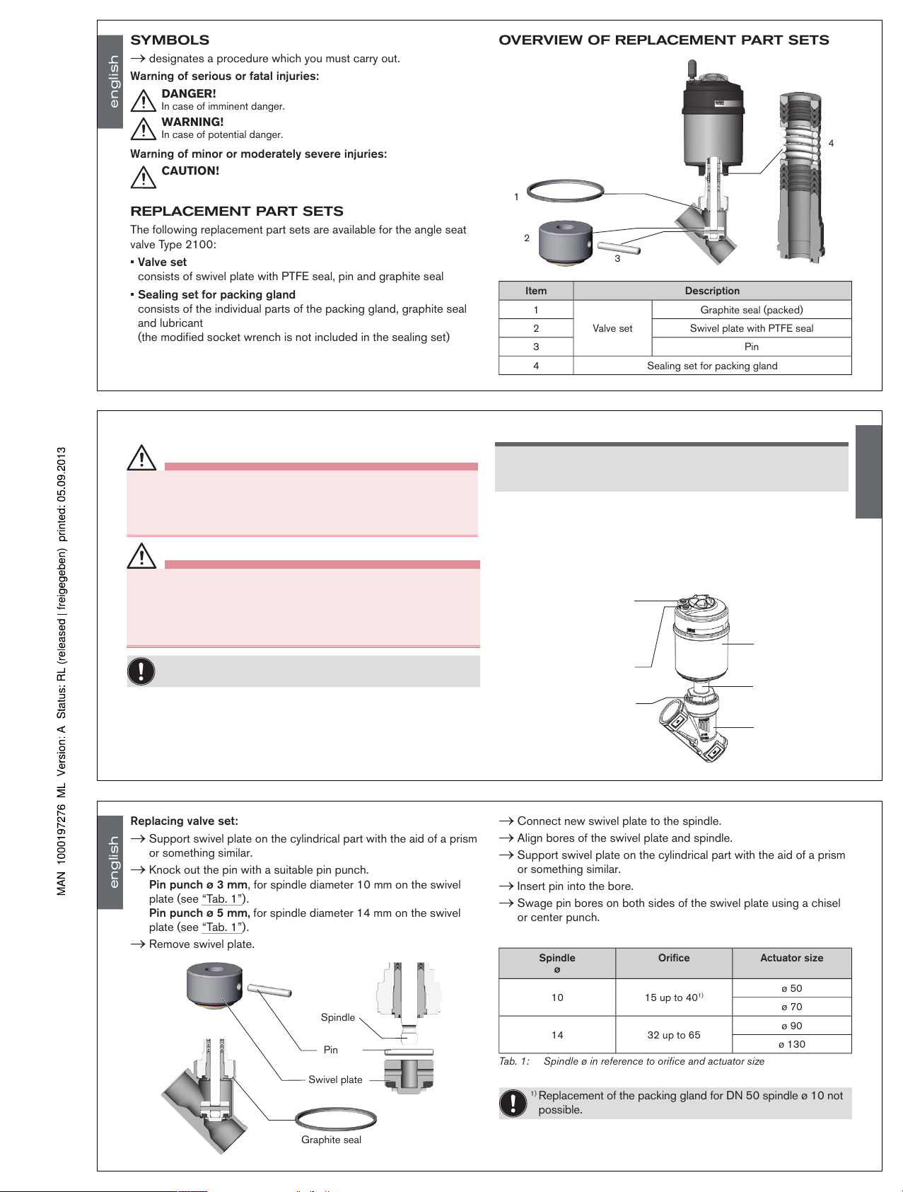
REPLACEMENT PART SETS
The following replacement part sets are available for the angle seat
valve Type 2100:
• Valve set
consists of swivel plate with PTFE seal, pin and graphite seal
• Sealing set for packing gland
consists of the individual parts of the packing gland, graphite seal
and lubricant
(the modified socket wrench is not included in the sealing set)
OVERVIEW OF REPLACEMENT PART SETS
1
2
3
4
Item Description
1
Valve set
Graphite seal (packed)
2 Swivel plate with PTFE seal
3 Pin
4 Sealing set for packing gland
english
NOTE!
Damage to the seat seal or the seat contour!
• When removing the actuator, ensure that the valve is in open
position.
→ Control function A pressurize the pilot air port 1 with compressed
air (5 bar): valve opens.
→ Using a suitable open-end wrench, place the wrench flat on the
tube.
→ Unscrew the actuator from the valve body.
Actuator
Nipple
Valve body
Flats for open-end
wrench
Pilot air port
CFA, CFB, CFI
Air discharge connection
CFA, CFB
Pilot air port
CFI
2
1
REPLACING THE VALVE SET
DANGER!
Risk of injury from discharge of medium and pressure!
It is dangerous to remove a device which is under pressure due to
the sudden release of pressure or discharge of medium.
• Before removing a device, switch off the pressure and vent the lines.
WARNING!
Risk of injury if the wrong tools are used!
It is dangerous to use unsuitable tools for installation work as the
device may be damaged.
• To remove the actuator from the valve body, use an open-end wrench,
never a pipe wrench.
Before the valve set can be replaced, the actuator must be
removed from the valve body.
Remove the actuator from the valve body:
→ Clamp the valve body in a holding device
(applies only to valves which have not yet been installed).
english
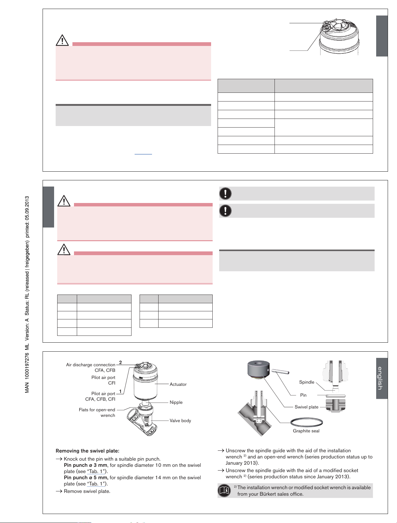
Replacing valve set:
→ Support swivel plate on the cylindrical part with the aid of a prism
or something similar.
→ Knock out the pin with a suitable pin punch.
Pin punch ø 3 mm, for spindle diameter 10 mm on the swivel
plate (see “Tab. 1”).
Pin punch ø 5 mm, for spindle diameter 14 mm on the swivel
plate (see “Tab. 1”).
→ Remove swivel plate.
Spindle
Pin
Swivel plate
Graphite seal
→ Connect new swivel plate to the spindle.
→ Align bores of the swivel plate and spindle.
→ Support swivel plate on the cylindrical part with the aid of a prism
or something similar.
→ Insert pin into the bore.
→ Swage pin bores on both sides of the swivel plate using a chisel
or center punch.
Spindle
ø
Orifice Actuator size
10 15 up to 40
1)
ø 50
ø 70
14 32 up to 65
ø 90
ø 130
Tab. 1: Spindle ø in reference to orifice and actuator size
1)
Replacement of the packing gland for DN 50 spindle ø 10 not
possible.
english
Type 2100
Page 3
Installing the actuator on the valve body:
→ Check the graphite seal and if required, replace it.
WARNING!
Danger if incorrect lubricants used!
Unsuitable lubricant may contaminate the medium. In oxygen applications there is a risk of an explosion!
• In specific applications, e.g. oxygen or analysis applications, use
appropriately authorised lubricants only.
→ Grease nipple thread before re-installing the actuator (e.g. with
Klüber paste UH1 96-402 from Klüber).
NOTE!
Damage to the seat seal or the seat contour!
• When installing the actuator, ensure that the valve is in open
position.
→ Control function A pressurize the pilot air port 1 with compressed
air (5 bar): valve opens.
→ Screw actuator into the valve body.
Observe tightening torque (see “Tab. 2”).
1
2
Pilot air port
CFA, CFB, CFI
Air discharge connection
CFA, CFB
Pilot air port
CFI
Tightening torque
Orifice
(mm)
Tightening torque
[Nm]
15 45 ± 3
20 50 ± 3
25 60 ± 3
32
65 ± 3
40
50
70 ± 3
65
100 ±3
Tab. 2: Tightening torque of valve body / nipples
english
CHANGING THE SEAL SET
WARNING!
Risk of injury if the wrong tools are used!
It is dangerous to use unsuitable tools for installation work as the
device may be damaged.
• To remove the actuator from the valve body, use an open-end
wrench, never a pipe wrench.
DANGER!
Risk of injury from discharge of medium and pressure!
It is dangerous to remove a device which is under pressure due to
the sudden release of pressure or discharge of medium.
• Before removing a device, switch off the pressure and vent the lines.
The seal set for the packing gland contains:
Item Description Item Description
1 1 Support ring 5 1 Spindle guide
2 7 Chevron seals 6 Graphite seal
3 2 Pressure rings 7 Lubricant
4 1 Pressure spring
The packing gland cannot be replaced for the device
combination ø 70 / orifice 50.
Before the packing gland can be replaced, the actuator must
be removed from the valve body and the swivel plate removed.
Remove the actuator from the valve body:
→ Clamp the valve body in a holding device
(applies only to valves which have not yet been installed).
NOTE!
Damage to the seat seal or the seat contour!
• When removing the actuator, ensure that the valve is in open
position.
→ Control function A pressurize the pilot air port 1 with compressed
air (5 bar): valve opens.
→ Using a suitable open-end wrench, place the wrench flat on the
tube.
→ Unscrew the actuator from the valve body.
english
Actuator
Nipple
Valve body
Flats for open-end
wrench
Pilot air port
CFA, CFB, CFI
Air discharge connection
CFA, CFB
Pilot air port
CFI
2
1
Removing the swivel plate:
→ Knock out the pin with a suitable pin punch.
Pin punch ø 3 mm, for spindle diameter 10 mm on the swivel
plate (see “Tab. 1”).
Pin punch ø 5 mm, for spindle diameter 14 mm on the swivel
plate (see “Tab. 1”).
→ Remove swivel plate.
Spindle
Pin
Swivel plate
Graphite seal
→ Unscrew the spindle guide with the aid of the installation
wrench 2) and an open-end wrench (series production status up to
January 2013).
→ Unscrew the spindle guide with the aid of a modified socket
wrench 2) (series production status since January 2013).
2)
The installation wrench or modified socket wrench is available
from your Bürkert sales office.
english
Type 2100
Page 4
Installation wrench
Packing gland
Spindle guide
Spindle
Packing gland tube
Series production
status up to January
2013
Packing gland
Spindle guide
Spindle
Packing gland tube
Series production
status since January
2013
WARNING!
Risk of injury from parts jumping out!
When the spindle opening is exposed, the individual parts of the
packing gland are pressed out at an undefined speed when the
pilot air ports is pressurized.
• Before pressurizing with control air, safeguard the ambient area of
the discharge opening (e.g. place spindle on a firm base).
→ Control function A and I Pressurize pilot air port 1 with 6 – 8 bar.
→ Control function B Pressurize pilot air port 2 with 6 – 8 bar.
→ Grease the individual parts of the new packing gland with the
upplied lubricant.
→ Connect the individual parts to the spindle in the specified
direction and sequence.
→ Push packing gland into the packing gland tube.
→ Screw spindle guide back in using the installation tool. Observe
torque (see “Tab. 3”)!
english
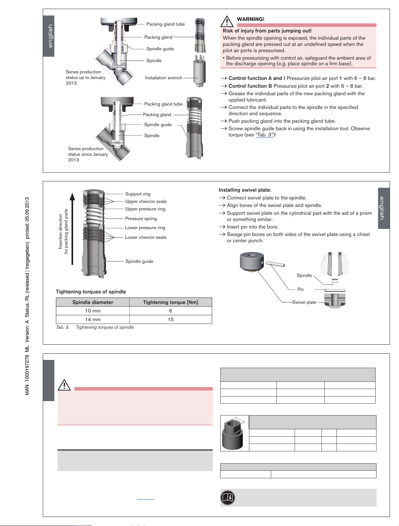
Support ring
Upper chevron seals
Upper pressure ring
Pressure spring
Lower pressure ring
Lower chevron seals
Spindle guide
Insertion direction
for packing gland parts
Tightening torques of spindle
Spindle diameter Tightening torque [Nm]
10 mm 6
14 mm 15
Tab. 3: Tightening torques of spindle
Installing swivel plate:
→ Connect swivel plate to the spindle.
→ Align bores of the swivel plate and spindle.
→ Support swivel plate on the cylindrical part with the aid of a prism
or something similar.
→ Insert pin into the bore.
→ Swage pin bores on both sides of the swivel plate using a chisel
or center punch.
Spindle
Pin
Swivel plate
english
Installing the actuator on the valve body:
→ Check the graphite seal and if required, replace it.
WARNING!
Danger if incorrect lubricants used!
Unsuitable lubricant may contaminate the medium. In oxygen applications there is a risk of an explosion!
• In specific applications, e.g. oxygen or analysis applications, use
appropriately authorised lubricants only.
→ Grease nipple thread before re-installing the actuator (e.g. with
Klüber paste UH1 96-402 from Klüber).
NOTE!
Damage to the seat seal or the seat contour!
• When installing the actuator, ensure that the valve is in open
position.
→ Control function A pressurize the pilot air port 1 with compressed
air (5 bar): valve opens.
→ Screw actuator into the valve body.
Observe tightening torque (see “Tab. 2”).
INSTALLATION TOOLS
Installation wrench for packing gland
(Only for removal of packing glands up to January 2013)
Installation wrench Orifice Order no.
Spindle ∅ 10 mm 15 - 40 665 700
Spindle ∅ 14 mm 32 - 65 665 701
Tab. 4: Installation wrench
SW
Modified socket wrench for packing gland
(Series production status since January 2013)
Socket wrench Orifice SW Order no.
Spindle ∅ 10 mm 15 - 40 19 683 221
Spindle ∅ 14 mm
32 - 65 21 683 223
Tab. 5: Modified socket wrench
Special wrench for rotating the actuator
Order no.
665 702
Tab. 6: Special wrench
If you have any queries, please contact your Bürkert sales
office.
english
Type 2100
Page 5

Austauschanleitung
Instructions de remplacement
Replacement Instructions
Type 2100
2/2-way Angle Seat Valve
2/2-Wege Schrägsitzventil
Vanne à siège incliné 2/2 voies
Address / Adresse
Germany / Deutschland / Allemagne
Bürkert Fluid Control Systems
Sales Center
Christian-Bürkert-Str. 13-17
D-74653 Ingelfingen
Tel. + 49 (0) 7940 - 10 91 111
Fax + 49 (0) 7940 - 10 91 448
E-mail: info@de.buerkert.com
International
www.burkert.com
Manuals and data sheets on the Internet:
www.burkert.com
Bedienungsanleitungen und Datenblätter im Internet:
www.buerkert.de
Instructions de service et fiches techniques sur Internet :
www.buerkert.fr
© Bürker t Werke GmbH, 2013
Replacement Instructions 1309/01_EU-ml_00810231 /
Original DE
www.burkert.com
Page 6

DARSTELLUNGSMITTEL
→ markiert einen Arbeitsschritt, den Sie ausführen müssen.
Warnung vor schweren oder tödlichen Verletzungen:
GEFAHR!
Bei unmittelbarer Gefahr.
WARNUNG!
Bei möglicher Gefahr.
Warnung vor leichten oder mittelschweren Verletzungen:
VORSICHT!
ERSATZTEILSÄTZE
Als Ersatzteilsätze für das Schrägsitzventil Typ 2100 sind erhältlich:
• Ventilsatz
besteht aus Pendelteller mit PTFE Dichtung, Steckstift und
Graphitdichtung
• Dichtungssatz für Stopfbuchse
besteht aus den Einzelteilen der Stopfbuchse, Graphitdichtung und
Schmierstoff
(der modifizierte Steckschlüssel ist nicht im Dichtungssatz enthalten)
ÜBERSICHT ERSATZTEILSÄTZE
1
2
3
4
Pos. Beschreibung
1
Ventilsatz
Graphitdichtung (verpackt)
2 Pendelteller mit PTFE Dichtung
3 Steckstift
4 Dichtungssatz für Stopfbuchse
deutsch
HINWEIS!
Beschädigung der Sitzdichtung bzw. der Sitzkontur!
• Das Ventil muss sich bei der Demontage des Antriebs in geöffneter
Stellung befinden.
→ Bei Steuerfunktion A (SFA): den Steuerluftanschluss 1 mit Druckluft
(5 bar) beaufschlagen: Ventil öffnet.
→ An der Schlüsselfläche des Nippels mit passendem Gabelschlüssel
ansetzen.
→ Antrieb vom Ventilgehäuse abschrauben.
Antrieb
Nippel
Ventilgehäuse
Schlüsselfläche
für Gabelschlüssel
Steuerluftanschluss
SFA, SFB, SFI
Entlüftungsanschluss
SFA, SFB
Steuerluftanschluss
SFI
2
1
WECHSEL DES VENTILSATZES
GEFAHR!
Verletzungsgefahr durch Mediumsaustritt und Druckentladung!
Der Ausbau eines Geräts das unter Druck steht ist wegen plötzlicher
Druckentladung oder Mediumsaustritt gefährlich.
• Vor dem Ausbau den Druck abschalten und Leitungen entlüften.
WARNUNG!
Verletzungsgefahr durch falsches Werkzeug!
Montagearbeiten mit ungeeignetem Werkzeug sind wegen der möglichen Beschädigung des Geräts gefährlich.
• Zur Demontage des Antriebs vom Ventilgehäuse einen Gabelschlüssel, keinesfalls eine Rohrzange verwenden.
Für den Austausch des Ventilsatzes muss zunächst der Antrieb
vom Ventilgehäuse demontiert werden.
Antrieb vom Ventilgehäuse demontieren:
→ Ventilgehäuse in eine Haltevorrichtung einspannen (gilt nur für
noch nicht eingebaute Ventile).
deutsch
Ventilsatz tauschen:
→ Pendelteller am zylindrischen Teil mit Hilfe eines Prismas oder etwas
Ähnlichem abstützen.
→ Steckstift mit einem passenden Splinttreiber herausschlagen.
Splinttreiber ø 3 mm, bei Spindeldurchmesser 10 mm am
Pendelteller (siehe „Tab. 1“).
Splinttreiber ø 5 mm, bei Spindeldurchmesser 14 mm am
Pendelteller (siehe „Tab. 1“).
→ Pendelteller abziehen.
Spindel
Steckstift
Pendelteller
Graphitdichtung
→ Neuen Pendelteller auf die Spindel stecken.
→ Bohrungen von Pendelteller und Spindel zueinander fluchtend
ausrichten.
→ Pendelteller am zylindrischen Teil mit Hilfe eines Prismas oder
etwas Ähnlichem abstützen.
→ Steckstift in die Bohrung einsetzen.
→ Steckstiftbohrungen am Pendelteller beidseitig mit Meißel oder
Körner verstemmen.
Spindel
ø
DN Antriebsgröße
10 15 bis 40
1)
ø 50
ø 70
14 32 bis 65
ø 90
ø 130
Tab. 1: Spindel ø in Bezug zu DN und Antriebsgröße
1)
Austausch der Stopfbuchse für DN 50 Spindel ø 10 nicht
möglich.
deutsch
Typ 2100
Page 7

Antrieb auf Ventilgehäuse montieren:
→ Graphitdichtung prüfen und bei Bedarf erneuern.
WARNUNG!
Gefahr durch falsche Schmierstoffe!
Ungeeigneter Schmierstoff kann das Medium verunreinigen. Bei
Sauerstoffanwendungen besteht dadurch Explosionsgefahr!
• Bei spezifischen Anwendungen wie z. B. Sauerstoff- oder Analyseanwendungen nur entsprechend zugelassene Schmierstoffe
verwenden.
→ Nippelgewinde vor Wiedereinbau des Antriebs einfetten (z. B. mit
Klüberpaste UH1 96-402 der Fa. Klüber).
HINWEIS!
Beschädigung der Sitzdichtung bzw. der Sitzkontur!
• Das Ventil muss sich bei der Montage des Antriebs in geöffneter
Stellung befinden.
→ Bei Steuerfunktion A den Steuerluftanschluss 1 mit Druckluft (5 bar)
beaufschlagen: Ventil öffnet.
→ Antrieb in das Ventilgehäuse einschrauben. Anziehdrehmoment
beachten (siehe „Tab. 2“).
1
2
Steuerluftanschluss
SFA, SFB, SFI
Entlüftungsanschluss
SFA, SFB
Steuerluftanschluss
SFI
Anziehdrehmomente
DN
(mm)
Anziehdrehmomente
[Nm]
15 45 ± 3
20 50 ± 3
25 60 ± 3
32
65 ± 3
40
50
70 ± 3
65
100 ±3
Tab. 2: Anziehdrehmomente Ventilgehäuse / Nippel
deutsch
WECHSEL DES DICHTUNGSSATZES
WARNUNG!
Verletzungsgefahr durch falsches Werkzeug!
Montagearbeiten mit ungeeignetem Werkzeug sind wegen der möglichen Beschädigung des Geräts gefährlich.
• Zur Demontage des Antriebs vom Ventilgehäuse einen Gabelschlüssel, keinesfalls eine Rohrzange verwenden.
GEFAHR!
Verletzungsgefahr durch Mediumsaustritt und Druckentladung!
Der Ausbau eines Geräts das unter Druck steht ist wegen plötzlicher
Druckentladung oder Mediumsaustritt gefährlich.
• Vor dem Ausbau den Druck abschalten und Leitungen entlüften.
Der Dichtungssatz für die Stopfbuchse enthält:
Pos. Beschreibung Pos. Beschreibung
1 1 Stützring 5 1 Spindelführung
2 7 Dachmanschetten 6 Graphitdichtung
3 2 Druckringe 7 Schmierstoff
4 1 Druckfeder
Bei der Gerätekombination ø 70 / DN 50 ist der Austausch der
Stopfbuchse nicht möglich.
Für den Austausch der Stopfbuchse muss zunächst der
Antrieb vom Ventilgehäuse demontiert und der Pendelteller
ausgebaut werden.
Antrieb vom Ventilgehäuse demontieren:
→ Ventilgehäuse in eine Haltevorrichtung einspannen (gilt nur für
noch nicht eingebaute Ventile).
HINWEIS!
Beschädigung der Sitzdichtung bzw. der Sitzkontur!
• Das Ventil muss sich bei der Demontage des Antriebs in geöffneter
Stellung befinden.
→ Bei Steuerfunktion A den Steuerluftanschluss 1 mit Druckluft (5
bar) beaufschlagen: Ventil öffnet.
→ An der Schlüsselfläche des Nippels mit passendem Gabelschlüssel
ansetzen.
→ Antrieb vom Ventilgehäuse abschrauben.
deutsch
Antrieb
Nippel
Ventilgehäuse
Schlüsselfläche
für Gabelschlüssel
Steuerluftanschluss
SFA, SFB, SFI
Entlüftungsanschluss
SFA, SFB
Steuerluftanschluss
SFI
2
1
Pendelteller demontieren:
→ Steckstift mit einem passenden Splinttreiber herausschlagen.
Splinttreiber ø 3 mm, bei Spindeldurchmesser 10 mm am
Pendelteller (siehe „Tab. 1“).
Splinttreiber ø 5 mm, bei Spindeldurchmesser 14 mm am
Pendelteller (siehe „Tab. 1“).
→ Pendelteller abziehen.
Spindel
Steckstift
Pendelteller
Graphitdichtung
→ Spindelführung mit Hilfe des Montageschlüssels
2)
und eines Gabel-
schlüssels herausschrauben (Serienstand bis Januar 2013).
→ Spindelführung mit Hilfe eines modifizierten Steckschlüssels
2)
herausschrauben (Serienstand ab Januar 2013).
2)
Der Montageschlüssel bzw. modifizierter Steckschlüssel
sind über Ihre Bürkert-Vertriebsniederlassung erhältlich.
deutsch
Typ 2100
Page 8

Montageschlüssel
Stopfbuchse
Spindelführung
Spindel
Stopfbuchsenrohr
Serienstand
bis Januar 2013
Stopfbuchse
Spindelführung
Spindel
Stopfbuchsenrohr
Serienstand
ab Januar 2013
WARNUNG!
Verletzungsgefahr durch herausspringende Teile!
Bei freiliegender Spindelöffnung werden beim Beaufschlagen des
Steuerluftanschlusses die Einzelteile der Stopfbuchse mit undefinierter
Geschwindigkeit herausgedrückt.
• Vor dem Beaufschlagen mit Steuerluft den Umgebungsbereich der
Austrittsöffnung absichern (z. B. Spindel auf eine feste Unterlage
aufsetzen).
→ Bei Steuerfunktion A und I den Steuerluftanschluss 1 mit 6 ... 8
bar beaufschlagen.
→ Bei Steuerfunktion B den Steuerluftanschluss 2 mit 6 ... 8 bar
beaufschlagen.
→ Die Einzelteile der neuen Stopfbuchse mit dem mitgelieferten
Schmierstoff einfetten.
→ Die Einzelteile in vorgegebener Richtung und Reihenfolge auf die
Spindel stecken.
→ Stopfbuchsenpackung in das Stopfbuchsenrohr schieben.
→ Spindelführung unter Verwendung des Steckschlüssels wieder
einschrauben. Anziehdrehmoment beachten (siehe „Tab. 3“)!
deutsch
Stützring
obere Dachmanschetten
oberer Druckring
Druckfeder
unterer Druckring
untere Dachmanschetten
Spindelführung
Einschieberichtung
für Stopfbuchsenteile
Anziehdrehmomente Spindelführung
Spindeldurchmesser Anziehdrehmoment [Nm]
10 mm 6
14 mm 15
Tab. 3: Anziehdrehmomente Spindelführung
Pendelteller montieren:
→ Pendelteller auf die Spindel stecken.
→ Bohrungen von Pendelteller und Spindel zueinander fluchtend
ausrichten.
→ Pendelteller am zylindrischen Teil mit Hilfe eines Prismas oder etwas
Ähnlichem abstützen.
→ Steckstift in die Bohrung einsetzen.
→ Steckstiftbohrungen am Pendelteller beidseitig mit Meißel oder
Körner verstemmen.
Spindel
Steckstift
Pendelteller
deutsch
Antrieb auf Ventilgehäuse montieren:
→ Graphitdichtung prüfen und bei Bedarf erneuern.
WARNUNG!
Gefahr durch falsche Schmierstoffe!
Ungeeigneter Schmierstoff kann das Medium verunreinigen. Bei
Sauerstoffanwendungen besteht dadurch Explosionsgefahr!
• Bei spezifischen Anwendungen wie z. B. Sauerstoff- oder Analyseanwendungen nur entsprechend zugelassene Schmierstoffe
verwenden.
→ Nippelgewinde vor Wiedereinbau des Antriebs einfetten (z. B. mit
Klüberpaste UH1 96-402 der Fa. Klüber).
HINWEIS!
Beschädigung der Sitzdichtung bzw. der Sitzkontur!
• Das Ventil muss sich bei der Montage des Antriebs in geöffneter
Stellung befinden.
→ Bei Steuerfunktion A den Steuerluftanschluss 1 mit Druckluft (5 bar)
beaufschlagen: Ventil öffnet.
→ Antrieb in das Ventilgehäuse einschrauben. Anziehdrehmoment
beachten (siehe „Tab. 2“).
MONTAGEWERKZEUGE
Montageschlüssel für Stopfbuchse
(nur zur Demontage von Stopfbuchsen bis Januar 2013)
Montageschlüssel DN Bestellnummer
Spindel ∅ 10 mm 15 - 40 665 700
Spindel ∅ 14 mm 32 - 65 665 701
Tab. 4: Montageschlüssel
SW
Modifizierter Steckschlüssel für Stopfbuchse
(Serienstand ab Januar 2013)
Steckschlüssel DN SW Bestellnummer
Spindel ∅ 10 mm 15 - 40 19 683 221
Spindel ∅ 14 mm
32 - 65 21 683 223
Tab. 5: Modifizierter Steckschlüssel
Spezialschlüssel zum Drehen des Antriebs
Bestellnummer
665 702
Tab. 6: Spezialschlüssel
Wenden Sie sich bei Fragen bitte an Ihre
Bürkert-Vertriebsniederlassung.
deutsch
Typ 2100
Page 9

Austauschanleitung
Instructions de remplacement
Replacement Instructions
Type 2100
2/2-way Angle Seat Valve
2/2-Wege Schrägsitzventil
Vanne à siège incliné 2/2 voies
Address / Adresse
Germany / Deutschland / Allemagne
Bürkert Fluid Control Systems
Sales Center
Christian-Bürkert-Str. 13-17
D-74653 Ingelfingen
Tel. + 49 (0) 7940 - 10 91 111
Fax + 49 (0) 7940 - 10 91 448
E-mail: info@de.buerkert.com
International
www.burkert.com
Manuals and data sheets on the Internet:
www.burkert.com
Bedienungsanleitungen und Datenblätter im Internet:
www.buerkert.de
Instructions de service et fiches techniques sur Internet :
www.buerkert.fr
© Bürker t Werke GmbH, 2013
Replacement Instructions 1309/01_EU-ml_00810231 /
Original DE
www.burkert.com
Page 10

SYMBOLES
→ Identifie une opération que vous devez effectuer.
Mise en garde contre les blessures graves ou mortelles :
DANGER !
En cas de danger imminent.
AVERTISSEMENT !
En cas de danger possible.
Mise en garde contre les blessures légères ou moyennement graves :
PRUDENCE !
JEUX DE PIÈCES DE RECHANGE
Les jeux de pièces de rechange suivants sont disponibles pour la
vanne à siège incliné type 2100 :
• Jeu de vannes
comprenant le clapet plat avec joint PTFE, la goupille et le joint
graphite.
• Jeu de joints pour presse-étoupe
comprenant les pièces détachées du pack presse-étoupe, le joint
graphite et le lubrifiant
(la clé à pipe modifiée n’est pas comprise dans le jeu de joints).
VUE D’ENSEMBLE DES JEUX DE PIÈCES DE
RECHANGE
1
2
3
4
Pos. Description
1
Jeu de vannes
Joint graphite (emballé)
2 Clapet plat avec joint PTFE
3 Goupille
4 Jeu de joints pour presse-étoupe
français
REMARQUE !
Endommagement du joint ou du contour de siège.
• Lors de la démontage de l’actionneur, la vanne doit être en position
ouverte.
→ Avec la fonction A il convient d’appliquer de l’air comprimé
(5 bars) au raccord d’air de pilotage: ouverture da la vanne.
→ Positionner à l’aide d’une clé plate appropriée sur l’embout.
→ Dévisser l’actionneur du corps de vanne.
Actionneur
Embout
Corps de vanne
Méplat pour
clé à fourche
Raccord d’air de pilotage
CFA, CFB, CFI
Raccord de purge d’air
CFA, CFB
Raccord d’air de pilotage
CFI
2
1
REMPLACEMENT DU JEU DE VANNES
DANGER !
Risque de blessures dû à la sortie de fluide et à la décharge de
pression !
Le démontage d’un appareil sous pression est dangereux du fait de
la décharge de pression ou de la sortie de fluide soudaine.
• Avant le démontage, coupez la pression et purgez l’air des conduites.
AVERTISSEMENT !
Risque de blessures dû à de mauvais outils !
Les travaux de montage effectués avec des outils non appropriés
sont dangereux du fait de l’endommagement possible de l’appareil.
• Utilisez une clé plate pour démonter l’actionneur du corps de vanne,
en aucun cas une clé à tubes.
Le remplacement du jeu de vannes nécessite le démontage de
l’actionneur du corps de vanne.
Démonter l’actionneur du corps de vanne :
→ Serrer le corps de vanne dans un dispositif de maintien
(uniquement valable pour les vannes pas encore montées).
français
Remplacer le jeu de vannes :
→ Soutenir le clapet plat au niveau de la partie cylindrique à l‘aide
d‘un prisme ou semblable.
→ Sortir la goupille avec un chasse-goupilles adapté.
Chasse-goupilles ø 3 mm, pour diamètre de tige 10 mm sur le
clapet plat (voir « Tab. 1 »).
Chasse-goupilles ø 5 mm, pour diamètre de tige 14 mm sur le
clapet plat (voir « Tab. 1 »).
→ Retirer le clapet plat.
Tige
Goupille
Clapet plat
Joint graphite
→ Mettre un nouveau clapet plat sur la tige.
→ Aligner les alésages du clapet plat et de la tige de façon qu’ils
correspondent.
→ Soutenir le clapet plat au niveau de la partie cylindrique à l’aide
d’un prisme ou semblable.
→ Introduire la goupille dans l’alésage.
→ Assurer le blocage des deux côtés des alésages pour goupille sur
le disque pendulaire avec un burin ou un pointeau.
Tige
ø
Diamètre Taille de
l’actionneur
10 15 - 40
1)
ø 50
ø 70
14 32 - 65
ø 90
ø 130
Tab. 1 : Tige ø par référence à diamètre et taille de l’actionneur
1)
Impossible de remplacer le presse-étoupe de la broche DN 50
de ø 10.
français
Type 2100
Page 11

Monter l’actionneur sur le corps de vanne :
→ Contrôler le joint graphite et si nécessaire, le remplacer.
AVERTISSEMENT !
Danger dû à de mauvais lubrifiants !
Un lubrifiant non approprié peut encrasser le fluide. En cas d’applications
faisant usage d’oxygène il existe alors un risque d’explosion.
• Utilisez uniquement des lubrifiants homologués pour les applications
spécifiques comme par ex. celles faisant usage d’oxygène ou les
applications d’analyse.
→ Avant de remonter l’actionneur, lubrifiez le filet du embout
(par ex. de pâte Klüber UH1 96-402 de la société Klüber).
REMARQUE !
Endommagement du joint ou du contour de siège.
• Lors de la montage de l’actionneur, la vanne doit être en position
ouverte.
→ Avec la fonction A il convient d’appliquer de l’air comprimé (5
bars) au raccord d’air de pilotage: ouverture da la vanne.
→ Visser l’actionneur dans le corps de vanne. Respecter le couple de
serrage (voir « Tab. 2 »).
1
2
Raccord d’air de pilotage
CFA, CFB, CFI
Raccord de purge d’air
CFA, CFB
Raccord d’air de pilotage
CFI
Couples de serrage
Diamètre
(mm)
Couples de serrage
[Nm]
15 45 ± 3
20 50 ± 3
25 60 ± 3
32
65 ± 3
40
50
70 ± 3
65
100 ±3
Tab. 2 : Couples de serrage corps de vanne / embout
français
REMPLACEMENT DU JEU DE JOINTS
AVERTISSEMENT !
Risque de blessures dû à de mauvais outils !
Les travaux de montage effectués avec des outils non appropriés
sont dangereux du fait de l’endommagement possible de l’appareil.
• Utilisez une clé plate pour démonter l’actionneur du corps de vanne,
en aucun cas une clé à tubes.
DANGER !
Risque de blessures dû à la sortie de fluide et à la décharge de
pression !
Le démontage d’un appareil sous pression est dangereux du fait de
la décharge de pression ou de la sortie de fluide soudaine.
• Avant le démontage, coupez la pression et purgez l’air des conduites.
Le jeu de joints du presse-étoupe comprend :
Pos. Description Pos. Description
1 1 anneau de support 5 1 ressort de pression
2 7 manchettes de toit 6 Joint graphite
3 2 bagues de pression 7 Lubrifiant
4 1 guidage de tige
Avec la combinaison d’appareils ø 70 / diamètre 50 , le remplacement du presse-étoupe n’est pas possible.
Le remplacement du presse-étoupe nécessite le démontage
de l’actionneur du corps de vanne et du clapet plat.
Démonter l’actionneur du corps de vanne :
→ Serrer le corps de vanne dans un dispositif de maintien
(uniquement valable pour les vannes pas encore montées).
REMARQUE !
Endommagement du joint ou du contour de siège.
• Lors de la démontage de l’actionneur, la vanne doit être en position ouverte.
→ Avec la fonction A il convient d’appliquer de l’air comprimé (5 bars)
au raccord d’air de pilotage: ouverture da la vanne.
→ Positionner à l’aide d’une clé plate appropriée sur l’embout.
→ Dévisser l’actionneur du corps de vanne.
français
Actionneur
Embout
Corps de vanne
Méplat pour
clé à fourche
Raccord d’air de pilotage
CFA, CFB, CFI
Raccord de purge d’air
CFA, CFB
Raccord d’air de pilotage
CFI
2
1
Démonter le clapet plat :
→ Sortir la goupille avec un chasse-goupilles adapté.
Chasse-goupilles ø 3 mm, pour diamètre de tige 10 mm sur le
clapet plat (voir « Tab. 1 »).
Chasse-goupilles ø 5 mm, pour diamètre de tige 14 mm sur le
clapet plat (voir « Tab. 1 »).
→ Retirer le clapet plat.
Tige
Goupille
Clapet plat
Joint graphite
→ Dévisser le guidage de tige à l’aide d’un outil de montage et d’une
clé plate 2) (etat de série jusqu’en janvier 2013).
→ Dévisser le guidage de tige à l’aide d’une clé à pipe modifiée
2)
(etat de série à partir de janvier 2013).
2)
L’outil de montage ou la clé à pipe modifiée est disponible
auprès de votre filiale de distribution Bürkert.
français
Type 2100
Page 12

Clé de montage
Presse-étoupe
Guidage de tige
Tige
Tube presse-étoupe
Etat de série jusqu’en
janvier 2013
Presse-étoupe
Guidage de tige
Tige
Tube presse-étoupe
Etat de série
à partir de janvier
2013
AVERTISSEMENT !
Risque de blessures dû à l’éjection de pièces.
Lorsque l’ouverture de tige est libre et la pression est appliquée au
raccord d’air de pilotage, les pièces détachées du presse-étoupe
sortent à une vitesse non définie.
• Avant d’appliquer l’air de pilotage, sécurisez l’environnement de
l’ouverture de sortie (par ex. posez la tige sur un support solide).
→ Avec la fonction A et I raccord d‘air de pilotage 1 une pression
de 6 - 8 bars.
→ Avec la fonction B raccord d‘air de pilotage 2 une pression de
6 - 8 bars.
→ Lubrifier les pièces détachées du nouveau presse-étoupe du
lubrifiant fourni.
→ Positionner les pièces détachées dans le sens et l’ordre indiqués
sur la tige.
→ Insérer la garniture presse-étoupe dans le tube presse-étoupe.
→ Revisser le guidage de tige en utilisant l’outil de montage.
Respectez le couple de serrage (voir « Tab. 3 »)!
français
Anneau de support
Manchettes de toit supérieures
Bague de pression supérieure
Ressort de pression
Bague de pression inférieure
Manchettes de toit inférieures
Guidage de tige
Sens d’insertion pour
pièces de presse-étoupe
Couples de serrage de la tige
Diamètre de tige Couple de serrage [Nm]
10 mm 6
14 mm 15
Tab. 3 : Couples de serrage de la tige
Monter le clapet plat :
→ Mettre le clapet plat sur la tige.
→ Aligner les alésages du clapet plat et de la tige de façon qu’ils
correspondent.
→ Soutenir le clapet plat au niveau de la partie cylindrique à l’aide
d’un prisme ou semblable.
→ Introduire la goupille dans l’alésage.
→ Assurer le blocage des deux côtés des alésages pour goupille sur
le clapet plat avec un burin ou un pointeau.
Tige
Goupille
Clapet plat
français
Monter l’actionneur sur le corps de vanne :
→ Contrôler le joint graphite et si nécessaire, le remplacer.
AVERTISSEMENT !
Danger dû à de mauvais lubrifiants !
Un lubrifiant non approprié peut encrasser le fluide. En cas d’applications
faisant usage d’oxygène il existe alors un risque d’explosion.
• Utilisez uniquement des lubrifiants homologués pour les applications
spécifiques comme par ex. celles faisant usage d’oxygène ou les
applications d’analyse.
→ Avant de remonter l’actionneur, lubrifiez le filet du embout
(par ex. de pâte Klüber UH1 96-402 de la société Klüber).
REMARQUE !
Endommagement du joint ou du contour de siège.
• Lors de la montage de l’actionneur, la vanne doit être en position
ouverte.
→ Avec la fonction A il convient d’appliquer de l’air comprimé
(5 bars) au raccord d’air de pilotage: ouverture da la vanne.
→ Visser l’actionneur dans le corps de vanne. Respecter le couple de
serrage (voir « Tab. 2 »).
OUTILS DE MONTAGE
Clé de montage pour presse-étoupe
(Uniquement pour le démontage des presse-étoupe jusqu’en janvier 2013)
Clé de montage Diamètre Numéro de commande
Tige ∅ 10 mm 15 - 40 665 700
Tige ∅ 14 mm 32 - 65 665 701
Tab. 4 : Clé de montage
SW
Clé à pipe modifiée pour presse-étoupe
(Etat de série à partir de janvier 2013)
Clé à pipe
modifiée
Diamètre SW
Numéro de
commande
Tige ∅ 10 mm 15 - 40 19 683 221
Tige ∅ 14 mm 32 - 65 21 683 223
Tab. 5 : Clé à pipe modifiée
Clé spéciale pour la rotation de l’actionneur
Numéro de commande
665 702
Tab. 6 : Clé spéciale
Si vous avez des questions, veuillez contacter votre filiale de
distribution Bürkert.
français
Type 2100
 Loading...