

Page 1
www.burkert.com
We reserve the right to make
technical changes without notice.
Technische Änderungen
vorbehalten.
Sous resérve de modification
techniques.
© 2008 - 2011 Bürkert Werke GmbH
Operating Instructions 1107/03_EU-ml_00805824
Operating Instructions
Bedienungsanleitung
Manuel d‘utilisation
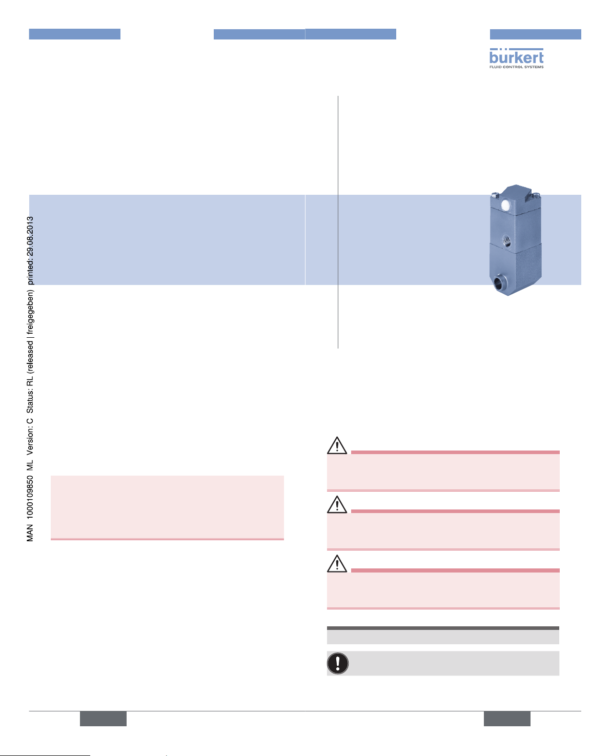
Type 2080
BELLOWS VALVE
2/2-way valve with piston actuator and PTFE bellows
2/2-Wege Ventil mit Kolbenantrieb und PTFE-Faltenbalg
Vanne 2/2 voies avec entraînement à piston et soufflet PTFE
english
2
1. OPERATING INSTRUCTIONS
The operating instructions describe the entire life cycle of the
device. Keep these instructions in a location which is easily
accessible to every user and make these instructions available
to every new owner of the device.
The operating instructions contain important safety
information!
Failure to observe these instructions may result in hazardous
situations.
• The operating instructions must be read and understood.
english
3
2. SYMBOLS
The following symbols are used in these instructions.
DANGER!
Warns of an immediate danger!
• Failure to observe the warning may result in a fatal or
serious injury.
WARNING!
Warns of a potentially dangerous situation!
• Failure to observe the warning may result in a serious or
fatal injury.
CAUTION!
Warns of a possible danger!
• Failure to observe this warning may result in a medium
or minor injury.
NOTE!
Warns of damage to property!
Important tips and recommendations.
→ designates a procedure which you must carry out.
Page 2
english
4
3. INTENDED USE
WARNING!
Incorrect use of the bellows valve Type 2080 can
be dangerous to people, nearby equipment and the
environment.
• The device is designed for the controlled flow of liquid
and gaseous media.
• For use observe the permitted data, operating and application conditions which are described in the contract
documents as well as on the type plate and in the operating instructions in the chapters entitled “Structure and
Function” and “Technical Data”.
• The device may be used only in conjunction with thirdparty devices and components recommended and authorised by Bürkert.
• Correct transport, correct storage and installation and
careful use and maintenance are essential for reliable and
problem-free operation.
• Use the bellows valve Type 2080 only as intended.
english
5
3.1. Possible errors in use
• Do not place any loads on the body (e.g. by placing
objects on it or standing on it).
• Do not make any external modifications to the valve
bodies.
• Do not introduce any aggressive or flammable media into
the pilot air connections of the system.
• Supply the media connections only with those media
which are specified as flow media in the chapter entitled
“Technical Data”.
english
6
4. BASIC SAFETY
INSTRUCTIONS
These safety instructions do not make allowance for any:
• Contingencies and events which may arise during the installation, operation and maintenance of the devices.
• Local safety regulations – the operator is responsible for
observing these regulations, also with reference to the
installation personnel.
DANGER!
Risk of injury from high pressure.
• Before loosening the lines and valves, turn off the pressure and vent the lines!
Risk of burns/fire from continuous operation!
When metering hot media, the device may become very
hot.
• Always wear protective gloves when handling a device
which controls hot media.
• Keep readily flammable materials and media away from
the device.
english
7
General hazardous situations.
To prevent injury, ensure that:
• The system cannot be activated unintentionally.
• Installation and repair work may be carried out by authorized technicians only and with the appropriate tools.
• After an interruption in the power supply or pneumatic
supply, ensure that the process is restarted in a defined
or controlled manner.
• The device may be operated only when in perfect condition and in consideration of the operating instructions.
• The general rules of technology apply to application planning and operation of the device.
Failure to observe this operating manual and its
operating instructions as well as unauthorized tampering with the device release us from any liability
and also invalidate the warranty covering the device
and accessories!
Type 2080
Page 3

english
8
5. GENERAL INFORMATION
5.1. Contact address
Germany
Bürkert Fluid Control Systems
Sales Center
Chr.-Bürkert-Str. 13-17
D-74653 Ingelfingen
Tel.: +49 (0)7940 - 10 91 111
Fax: +49 (0)7940 - 10 91 448
E-mail: info@de.burkert.com
International
Contact addresses can be found on the final pages of the
printed operating instructions.
And also on the internet at: www.burkert.com
5.2. Warranty
The warranty is only valid if the device valve Type 2080 is
used as intended in accordance with the specified application
conditions.
5.3. Information on the Internet
The operating instructions and data sheets for Type 2080 can
be found on the Internet at: www.burkert.com
english
9
6. STRUCTURE AND FUNCTION
6.1. Modularity
The valve is modular in design and can be supplied with
different media connections (also customized) and actuator
versions according to the application case. It can be used
individually and also in blocks.
6.2. Structure
The valve consists of a pneumatically actuated piston actuator
with return spring, a stainless steel body and PTFE bellows.
The bellows are used to separate media. If the installation
location is appropriate, the valve is self-draining.
The materials used and the inner contours facilitate cleaning
(CIP/SIP).
The pneumatic actuator must be controlled externally via a
pilot valve or a valve island.
english
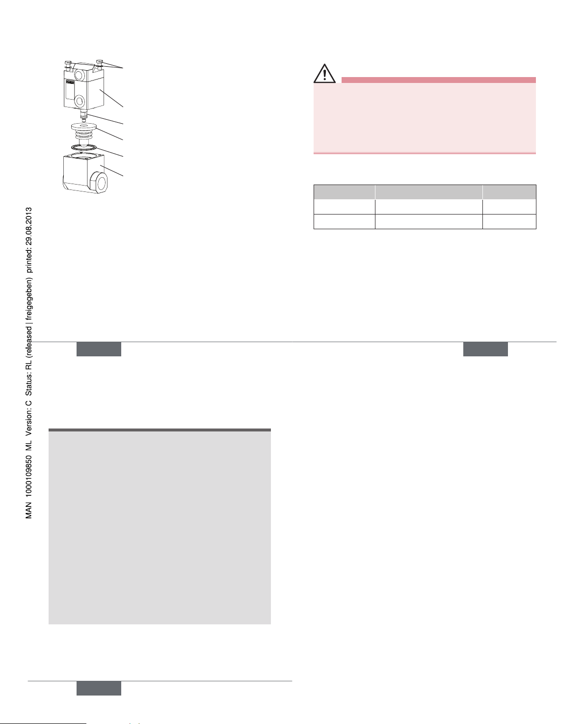
10
Bolts for attaching the
actuator to the body
Pilot air connections
Threaded ports G 1/8
Connection CF B (NO)
Connection CF A (NC)
Flange Threaded port Welded end
G 3/8
Media connections
Notch for monitoring of
bellow leakage
english
11
7. TECHNICAL DATA
7.1. Operating Conditions
Ambient temperature -10 ... +90 °C
Medium temperature -30 ... +150 °C
(see PT graph)
Media Neutral to aggressive gases
and liquids, technical vacuum
7.2. Restrictions
For Valves with a flow inlet over seat:
WARNING!
Risk of injury from water hammer.
If flow inlet over seat with liquid media, water hammers may
occur. As a consequence, lines or the device may burst
and medium flow out.
• Consider the type of flow inlet and the type of medium
for operation of the device.
• If flow inlet over seat before the use of liquid media,
to avoid water hammers, in case of doubt, clarify the
application conditions (medium, line length and crosssection) with the Bürkert sales office.
Type 2080
Page 4
english
12
7.3. Conformity
The device conforms to the EC directives according to the
EC Declaration of Conformity.
7.4. Standards
The conformity with EC guidelines is guaranteed in accordance with standards:
• EN 13463-1, EN 13463-5
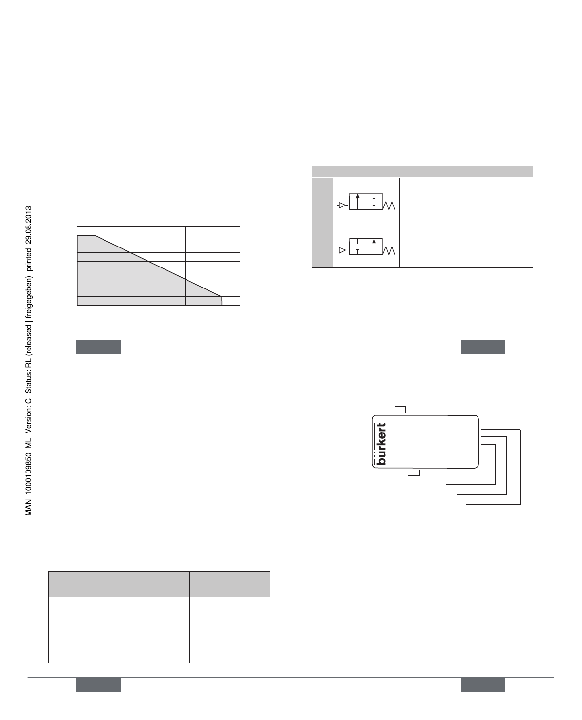
7.5. PT graph
Permitted pressure-temperature compatibility of the PTFE
bellows
(Pressure value [bar]: Measured as overpressure to the
atmospheric pressure)
0
0 20 40 60 80 100 120
140
160 180
1
2
3
4
5
6
7
8
9
Permitted
range
P [bar]
T [°C]
english
13
7.6. Mechanical Data
Dimensions See data sheet
Body material
Fitting Stainless steel 316L (1.4404)
Actuator Stainless steel 304 (1.4301)
Bellows PTFE
Bellows stroke 2.5 mm
Internal surface finish Ra = 0.8 µm
7.7. Fluidic data
Circuit functions
A
A
P
2/2-way valve, servo-assisted,
closed without pilot air pressure
by spring force, actuation with
pilot valve, valve island or similar.
B
B
P
2/2-way valve, servo-assisted,
opened without pilot air pressure
by spring force, actuation with
pilot valve, valve island or similar.
Fitting
Pressure range of medium Vacuum ... 8 bar
(see PT graph)
Back pressure tightness up to 8 bar
english
14
Orifice DN 4 to DN 10
Line connections
Threaded port G 3/8
Welded ends
13.5 x 1.6 in accordance with ISO 4200
13 x 1.5 in accordance with DIN 1850-2
12.7 x 1.2 in accordance with BS 4825
Flange connection or
customized line connections
Actuator
Pilot air medium Compressed air 4.5 – 10 bar
(dry and filtered)
neutral gases
Pilot air connections Threaded port G 1/8
7.8. Actuator versions
Version
Operating
principle
Actuator Open - Closed CF A and CF B
Actuator Open - Closed
with position indicator
CF A and CF B
3 position actuator (with adjustable
intermediate position)
CF A
english
15
7.9. Label (example)
Made in Germany
00450000
W14UN
CE
Bellows valve
Type 2080 NC DN10
Pmax 8bar
Ppilot 4-10bar
Ident. no.
Nominal pressure
Type, Circuit function, Orifice
Description
Nominal pressure of pilot valve
Type 2080
Page 5
english
16
8. INSTALLATION
8.1. Safety Instructions
WARNING!
Risk of injury from improper installation!
• Installation may be carried out by authorized technicians
only and with the appropriate tools!
Risk of injury from unintentional activation of the
system and an uncontrolled restart!
• Secure system from unintentional activation.
• Following installation, ensure a controlled restart.
8.2. Fluid Installation
DANGER!
Danger – high pressure!
Serious risk of injury when reaching into the equipment.
• Before loosening the lines and valves, turn off the pressure and vent the lines.
Check that the operating conditions correspond
with the performance data of the device.
english
17
Installation position:
Installation can be in any position.
→ Install upright for self-draining (body to bottom and in
the case of threaded port and welded ends install at a
min. gradient of 1° for drainage of media).
Installation
→ Before installation, clean any possible dirt off the pipelines
and flange connections.
→ If necessary, install a dirt trap in front of the valve to protect
it from malfunctions.
Mesh size:
0.1 ... 0.4 mm
WARNING!
Danger - escaping medium!
Leaky connections with seals not properly seated.
• Fit all connections carefully and seal properly.
Seal the threaded port with a suitable sealing
material (PTFE tape is recommended).
english
18
Use the correct size of open-ended wrench to
screw in the pipelines; do not use the valve actuator
as a screwdriver!
The device must not be subject to any lateral
tension forces. The device connections must be in
alignment with the lines!
→ Attach the valve according to the connections:
Threaded port by screwing in the pipes,
Welded connection by welding,
Flange by screwing on.
Flange interface on the valve
16 16
Ø 4.5
Ø 3.1; 6 deep;
Option for positioning pin ø 3
(ensure correct location for installation)
16
16
13
english
19
8.3. Option: Valve with 3 position
actuator (with adjustable
intermediate position)
Functions of the valve:
• Closed (without pilot air, by spring force),
• Partial stroke (pilot air simultaneously on X and Y),
• Full stroke (pilot air on X only).
Adjusting spindle
Lock nut
Stroke setting on the spindle
Flange version
Y
X
Flow plus minus
Type 2080
Page 6

english
20
Setting the intermediate position:
→ attach a suitable flow measuring device (measuring
cup, flow meter, etc.),
→ loosen the lock nut,
→ connect pilot air to X and Y,
→ open the medium supply,
→ set the required flow on the adjusting spindle
stroke range = 0 to 2.5 mm (rotating the spindle
clockwise reduces the flow),
→ switch off the pilot air,
→ tighten the lock nut.
english
21
9. MAINTENANCE,
MALFUNCTIONS
9.1. Safety Instructions
DANGER!
Danger – high pressure in the equipment!
There is a serious risk of injury when reaching into the
equipment.
• Before loosening the lines and valves, turn off the
pressure and vent the lines.
WARNING!
Danger due to improper maintenance work!
Improper maintenance may result in injuries as well as
damage to the device and the surrounding area.
• Maintenance work may be carried out by authorised
technicians only and with the appropriate tools!
Danger due to unintentional activation of the equipment!
Unintentional activation of the equipment during maintenance
and repair work may result in injuries and/or damage.
• Take appropriate measures to prevent the equipment
from being unintentionally activated.
english
22
9.2. Maintenance / Cleaning
The bellows situated between the medium compartment and
actuator ensure that the valve switches reliably and protect
the medium from contaminants coming from the actuator
side. These bellows are subject to symptoms of fatigue. If the
bellows are defective, medium will escape out of the leakage
detection opening. To prevent them from being destroyed,
the bellows should be changed prophylactically at regular
intervals (see instructions on changing the bellows). The valve
interior has no gaps and the inner compartment and bellows
have been designed with very smooth contours (surface
roughness max. 0.8 µm). The valve is CIP compatible (CIP =
cleaning in process) and SIP compatible (SIP = sterilization
in process).
9.3. Changing the bellows
Removing the actuator
→ Provide the required spare parts and a size 7 open-
ended wrench,
→ Interrupt the pilot air supply, vent and disconnect the
lines,
→ Interrupt the medium supply and vent the lines,
→ Loosen both fastening screws,
→ Remove the actuator.
english
23
Changing the bellows
→ Unscrew the bellows from the spindle,
→ Clean the inner compartment of the body,
→ Manually screw the new bellows onto the spindle and
tighten them hand-tight.
Attaching the actuator
→ Clean the O-ring 25 x 2 FKM 70 in the body, check
whether it can be re-used and, if required, replace it
with a new O-ring
→ Place the actuator with new bellows on the body;
ensure that the bores in the actuator are correctly
aligned with the thread in the body
→ Attach the actuator to the body with the fastening
screws (tightening torque from 2 to 2.2 Nm).
Restarting the bellows valve
→ Connect the pilot air line,
→ Open the pilot air,
→ Open the medium supply,
→ Conduct a function and leak test,,
→ If the valve functions reliably, it can be restarted.
Type 2080
Page 7
english
24
Exploded drawing of changing spare parts, Type 2080
Hexagon screws M4 x 50 in accordance with DIN 933-A4 for attaching
the actuator to the body
Actuator
Spindle
PTFE bellows
O-ring 25 x 2 FKM 70
Body (threaded port version)
9.4. Malfunctions
If malfunctions occur, check:
→ the line connections,
→ the operating pressure,
→ the pilot air supply which actuates the valve,
→ the bellows and, if required, change them (see chapter
9.3).
If the valve still does not switch, please contact your
Bürkert Service.
english
25
10. REPLACEMENT PARTS
CAUTION!
Risk of injury and/or damage by the use of incorrect
parts!
Incorrect accessories and unsuitable spare parts may cause
injuries and damage the device and the surrounding area.
• Use only original accessories and original replacement
parts from Bürkert.
Order table of spare parts
Spare part Description Order no.
Bellows Material PTFE 799 845
O-ring 25 x 2.0 N-FKM 70 914 378
english
26
11. TRANSPORT, STORAGE,
DISPOSAL
NOTE!
Transport damages!
Inadequately protected equipment may be damaged
during transport.
• During transportation protect the device against wet
and dirt in shock-resistant packaging.
• Avoid exceeding or dropping below the allowable
storage temperature.
Incorrect storage may damage the device.
• Store the device in a dry and dust-free location!
• Storage temperature: -20 ... +65 °C.
Damage to the environment caused by device components contaminated with media.
• Observe applicable regulations on disposal and the
environment.
• Dispose of the device and packaging in an environmentally friendly manner.
Page 8

www.burkert.com
We reserve the right to make
technical changes without notice.
Technische Änderungen
vorbehalten.
Sous resérve de modification
techniques.
© 2008 - 2011 Bürkert Werke GmbH
Operating Instructions 1107/03_EU-ml_00805824
Bedienungsanleitung
Deutsch
Type 2080
FALTENBALGVENTIL
2/2-Wege Ventil mit Kolbenantrieb und PTFE-Faltenbalg
deutsch
28
1. DIE BEDIENUNGSANLEITUNG
Die Bedienungsanleitung beschreibt den gesamten Lebenszyklus des Gerätes. Bewahren Sie diese Anleitung so auf,
dass sie für jeden Benutzer gut zugänglich ist und jedem
neuen Eigentümer des Gerätes wieder zur Verfügung steht.
Die Bedienungsanleitung enthält wichtige Informationen zur Sicherheit!
Das Nichtbeachten dieser Hinweise kann zu gefährlichen
Situationen führen.
• Die Bedienungsanleitung muss gelesen und verstanden
werden.
29
deutsch
2. DARSTELLUNGSMITTEL
In dieser Anleitung werden folgende Darstellungsmittel
verwendet.
GEFAHR!
Warnt vor einer unmittelbaren Gefahr!
• Bei Nichtbeachtung sind Tod oder schwere Verletzungen die Folge.
WARNUNG!
Warnt vor einer möglicherweise gefährlichen Situation!
• Bei Nichtbeachtung können schwere Verletzungen oder
Tod die Folge sein.
VORSICHT!
Warnt vor einer möglichen Gefährdung!
• Nichtbeachtung kann mittelschwere oder leichte Verletzungen zur Folge haben.
HINWEIS!
Warnt vor Sachschäden!
Wichtige Tipps und Empfehlungen.
→ markiert einen Arbeitsschritt den Sie ausführen müssen.
Page 9

deutsch
30
3. BESTIMMUNGSGEMÄSSE
VERWENDUNG
Bei nicht bestimmungsgemäßem Einsatz des Faltenbalgventils Typ 2080 können Gefahren für Personen,
Anlagen in der Umgebung und die Umwelt entstehen.
• Das Gerät ist zur Regelung des Durchflusses von flüssigen und gasförmigen Medien konzipiert.
• Für den Einsatz sind die zulässigen Daten, Betriebs- und
Einsatzbedingungen zu beachten, die in den Vertragsdokumenten, sowie auf dem Typenschild und in der Bedienungsanleitung in den Kapiteln „Aufbau und Funktion“
und „Technische Daten“ beschrieben sind.
• Das Gerät nur in Verbindung mit von Bürkert empfohlenen bzw. zugelassenen Fremdgeräten und -komponenten
einsetzen.
• Voraussetzungen für den sicheren und einwandfreien
Betrieb sind sachgemäßer Transport, sachgemäße
Lagerung und Installation sowie sorgfältige Bedienung
und Instandhaltung.
• Das Gerät nur bestimmungsgemäß einsetzen.
31
deutsch
3.1. Vorhersehbarer Fehlgebrauch
• Das Gehäuse nicht mechanisch belasten (z. B. durch
Ablage von Gegenständen oder als Trittstufe).
• Keine äußerlichen Veränderungen an den Ventilgehäusen
vornehmen.
• In die Steueranschlüsse des Systems keine aggressiven
oder brennbaren Medien einspeisen.
• In die Medienanschlüsse nur Medien einspeisen, die im
Kapitel „Technische Daten“ als Durchflussmedien aufgeführt sind.
deutsch
32
4. GRUNDLEGENDE
SICHERHEITSHINWEISE
Diese Sicherheitshinweise berücksichtigen keine
• Zufälligkeiten und Ereignisse, die bei Montage, Betrieb
und Wartung der Geräte auftreten können.
• ortsbezogenen Sicherheitsbestimmungen, für deren
Einhaltung, auch in Bezug auf das Montagepersonal, der
Betreiber verantwortlich ist.
GEFAHR!
Verletzungsgefahr durch hohen Druck!
• Vor dem Lösen von Leitungen und Ventilen, den Druck
abschalten und Leitungen entlüften!
Verbrennungsgefahr/Brandgefahr bei Dauerbetrieb!
Das Gerät kann bei Dosierung heißer Medien sehr heiß
werden.
• Das Gerät steuert heiße Medien und darf nur mit Schutzhandschuhen angefasst werden.
• Leicht brennbare Stoffe und Medien vom Gerät fernhalten.
33
deutsch
Allgemeine Gefahrensituationen.
Zum Schutz vor Verletzungen ist zu beachten:
• Dass die Anlage nicht unbeabsichtigt betätigt werden
kann.
• Installations- und Instandhaltungsarbeiten dürfen nur von
autorisiertem Fachpersonal mit geeignetem Werkzeug
ausgeführt werden.
• Nach einer Unterbrechung der elektrischen Versorgung
ist ein definierter oder kontrollierter Wiederanlauf des
Prozesses zu gewährleisten.
• Das Gerät darf nur in einwandfreiem Zustand und unter
Beachtung der Bedienungsanleitung betrieben werden.
• Für die Einsatzplanung und den Betrieb des Gerätes
müssen die allgemeinen Regeln der Technik eingehalten
werden.
Bei Nichtbeachtung dieser Bedienungsanleitung
und ihrer Hinweise sowie bei unzulässigen Eingriffen
in das Gerät entfällt jegliche Haftung unsererseits,
ebenso erlischt die Gewährleistung auf Geräte und
Zubehörteile!
Typ 2080
Page 10

deutsch
34
5. ALLGEMEINE HINWEISE
5.1. Kontaktadresse
Deutschland
Bürkert Fluid Control Systems
Sales Center
Chr.-Bürkert-Str. 13-17
D-74653 Ingelfingen
Tel. : + 49 (0)7940 - 10 91 111
Fax: + 49 (0)7940 - 10 91 448
E-mail: info@de.burkert.com
International
Die Kontaktadressen finden Sie auf den letzten Seiten der
gedruckten Bedienungsanleitung.
Außerdem im Internet unter: www.burkert.com
5.2. Gewährleistung
Voraussetzung für die Gewährleistung ist der bestimmungsgemäße Gebrauch des Magnetventils Typ 2080 unter
Beachtung der spezifizierten Einsatzbedingungen.
5.3. Informationen im Internet
Bedienungsanleitungen und Datenblätter zum Typ 2080
finden Sie im Internet unter: www.buerkert.de
35
deutsch
6. AUFBAU UND FUNKTION
6.1. Modularität
Das Ventil ist modular aufgebaut und kann je nach Einsatzfall
mit verschiedenen Medienanschlüssen (auch kundenspezifisch) und Antriebsversionen geliefert werden.
Es ist einzeln und auch auf Blöcken einsetzbar.
6.2. Aufbau
Das Ventil besteht aus einem pneumatisch betätigten Kolbenantrieb mit Rückstellfeder, einem Edelstahlgehäuse und
einem PTFE-Faltenbalg. Der Faltenbalg dient zur Medientrennung. Bei entsprechender Einbaulage arbeitet das Ventil
selbstentleerend.
Die eingesetzten Materialien und die Innenkonturen ermöglichen eine einfache Reinigung (CIP/SIP).
Der pneumatische Antrieb muss extern über ein Pilotventil
oder eine Ventilinsel gesteuert werden.
deutsch
36
Schrauben zur Befestigung
des Antriebs am Gehäuse
Steuerluftanschlüsse
Muffen G 1/8
Anschluss WWB (NO)
Anschluss WWA (NC)
Flansch Muffe G 3/8 Schweißende
Medienanschlüsse
Öffnung zur Leckagekontrolle am Faltenbalg
37
deutsch
7. TECHNISCHE DATEN
7.1. Betriebsbedingungen
Umgebungstemperatur -10 ... +90 °C
Mediumstemperatur -30 ... +150 °C
(siehe PT-Diagramm)
Medien Neutrale bis aggressive Gase
und Flüssigkeiten,
technisches Vakuum
7.2. Einschränkungen
Für Ventile mit Anströmung über Sitz:
WARNUNG!
Verletzungsgefahr durch Schließschlag!
Bei Anströmung über Sitz mit flüssigen Medien kann es
zu Schließschlägen kommen. Als Folge davon können
Leitungen oder Gerät bersten und Medium ausströmen.
• Für den Betrieb des Gerätes die Art der Anströmung und
die Art des Mediums beachten.
• Bei Anströmung über Sitz vor dem Einsatz flüssiger
Medien, zur Vermeidung von Schließschlägen, im Zweifelsfall die Einsatzbedingungen (Medium, Leitungslängeund Querschnitt) mit der Bürkert Vertriebsniederlassung
abklären.
Typ 2080
Page 11

deutsch
38
7.3. Konformität
Das Faltenbalgventil Typ 2080 ist konform zu den EG-Richtlinien entsprechend der EG-Konformitätserklärung.
7.4. Normen
Durch folgende Normen wird die Konformität mit den EGRichtlinien erfüllt:
• EN 13463-1, EN 13463-5
7.5. PT-Diagramm
Zulässige Druck-Temperatur-Verträglichhkeit des PTFEFaltenbalges
(Druckangabe [bar]: Überdruck zum Atmosphärendruck).
0
0 20 40 60 80 100 120
140
160 180
1
2
3
4
5
6
7
8
9
Zulässiger
Bereich
P [bar]
T [°C]
39
deutsch
7.6. Mechanische Daten
Maße siehe Datenblatt
Gehäusematerial
Armatur Edelstahl 316L (1.4404)
Antrieb Edelstahl 304 (1.4301)
Faltenbalg PTFE
Hub Faltenbalg 2,5 mm
Oberflächengüte innen Ra = 0,8 µm
7.7. Fluidische Daten
Wirkungsweisen
A
A
P
2/2 Wege-Ventil, fremdgesteuert,
ohne Steuerdruck durch Federkraft geschlossen, Betätigung mit
Pilotventil, Ventilinsel o.ä.
B
B
P
2/2 Wege-Ventil, fremdgesteuert,
ohne Steuerdruck durch Federkraft geöffnet, Betätigung mit
Pilotventil, Ventilinsel o.ä.
Armatur
Druckbereich Medium Vakuum ... 8 bar
(siehe PT-Diagramm)
Rückdruckdichtheit bis 8 bar
deutsch
40
Nennweite DN 4 bis DN 10
Leitungsanschlüsse Muffenanschluss G 3/8
Schweißenden
13,5 x 1,6 nach ISO 4200
13 x 1,5 nach DIN 11850-2
12,7 x 1,2 nach BS 4825
Flanschanschluss oder
kundenspezifische Leitungsanschlüsse
Antrieb
Steuermedium Druckluft 4,5 ... 10 bar
(getrocknet und gefiltert)
neutrale Gase
Steuerluftanschlüsse Muffenanschluss G 1/8
7.8. Antriebsversionen
Version Wirkungsweise
Antrieb Auf - Zu WWA und WWB
Antrieb Auf - Zu
mit Stellungserfassung
WWA und WWB
3-Positions-Antrieb
(mit einstellbarer Zwischenposition)
WWA
41
deutsch
7.9. Typenschild (Beispiel)
Made in Germany
00450000
W14UN
CE
Faltenbalgventil
Typ 2080 NC DN10
Pmax 8bar
Ppilot 4-10bar
Ident-Nr.
Nenndruck
Typ, Wirkungsweise, Nennweite
Beschreibung
Nenndruck Pilotventil
Typ 2080
Page 12

deutsch
42
8. MONTAGE
8.1. Sicherheitshinweise
WARNUNG!
Verletzungsgefahr bei unsachgemäßer Montage!
• Die Montage darf nur autorisiertes Fachpersonal mit
geeignetem Werkzeug durchführen!
Verletzungsgefahr durch ungewolltes Einschalten der
Anlage und unkontrollierten Wiederanlauf!
• Anlage vor unbeabsichtigtem Betätigen sichern.
• Nach der Montage einen kontrollierten Wiederanlauf
gewährleisten.
8.2. Fluidische Installation
GEFAHR!
Gefahr durch hohen Druck!
Akute Verletzungsgefahr bei Eingriffen in die Anlage.
• Vor dem Lösen von Leitungen und Ventilen den Druck
abschalten und Leitungen entlüften.
Überprüfen Sie die Übereinstimmung der Betriebsbedingungen mit den Leistungsdaten des Gerätes.
43
deutsch
Einbaulage:
Die Einbaulage ist beliebig.
→ Für Selbstentleerung stehend einbauen (Armatur nach
unten und bei Muffenanschluss und Schweißenden
mindestens 1° geneigt für den Medienablauf einbauen).
Montage:
→ Vor der Montage Rohrleitungen und Flanschanschlüsse
von eventuellen Verschmutzungen säubern.
→ Zum Schutz vor Störungen gegebenenfalls einen
Schmutzfänger vor das Ventil einbauen.
Maschenweite:
0,1 ... 0,4 mm
WARNUNG!
Gefahr durch Mediumsaustritt!
Undichte Anschlüsse bei ungenauem Sitz der Dichtungen.
• Alle Anschlüsse sorgfältig und gut dichtend ausführen.
Zum Abdichten der Muffenanschlüsse geeignetes
Dichtmaterial verwenden (empfohlen wird
PTFE-Band).
deutsch
44
Zum Einschrauben der Rohrleitungen Gabelschlüssel
der passenden Schlüsselweite verwenden und den
Ventilantrieb nicht als Einschraubhebel benutzen!
Auf die Anschlüsse des Gerätes dürfen keine seitlichen Verspannungskräfte auftreten. Die Anschlüsse
des Gerätes und die Leitungen müssen fluchten!
→ Ventil entsprechend der Anschlüsse befestigen:
Muffenanschluss durch Einschrauben der Rohre,
Schweißanschluss durch Verschweißen,
Flansch durch Aufschrauben.
Flanschbild am Ventil
16 16
Ø 4,5
Ø 3,1; 6 tief;
Option für Positionierstift Ø 3 (Sicherstellung
der richtigen Lage beim Einbau)
16
16
13
45
deutsch
8.3. Option: Ventil mit 3-PositionsAntrieb (mit einstellbarer
Zwischenposition)
Funktionen des Ventils:
• Geschlossen (ohne Steuerluft, durch Federkraft),
• Teilhub - Position 1 (Steuerluft gleichzeitig an X und Y),
• Vollhub - Position 2 (Steuerluft nur an X).
Stellspindel
Kontermutter
Hubeinstellung an der Stellspindel
Flanschversion
Y
X
Durchfluss plus minus
Typ 2080
Page 13

deutsch
46
Einstellung der Zwischenposition:
→ Geeignete Durchflussmessung anbringen (Mess-
becher, Durchflussmesser o.ä.),
→ Kontermutter lösen,
→ Steuerluft an X und Y anschließen,
→ Medienzufuhr öffnen,
→ An der Stellspindel den gewünschten Durchfluss ein-
stellen
Hubbereich = 0 bis 2,5 mm (beim Drehen der Spindel
im Uhrzeigersinn wird der Durchfluss kleiner),
→ Steuerluft abstellen,
→ Kontermutter festziehen.
47
deutsch
9. WARTUNG, STÖRUNGEN
9.1. Sicherheitshinweise
GEFAHR!
Gefahr durch hohen Druck in der Anlage!
Bei Eingriffen in die Anlage besteht akute Verletzungsgefahr.
• Vor dem Lösen von Leitungen und Ventilen den Druck
abschalten und Leitungen entlüften.
WARNUNG!
Gefahr durch unsachgemäße Wartungsarbeiten!
Unsachgemäße Wartung kann zu Verletzungen sowie zu
Schäden am Gerät und seiner Umgebung führen.
• Wartungsarbeiten dürfen nur durch autorisiertes Fachpersonal und mit geeignetem Werkzeug durchgeführt
werden!
Gefahr durch unbeabsichtigte Betätigung der Anlage!
Ungewolltes Ingangsetzen der Anlage bei Wartungsund Reparaturarbeiten kann zu Verletzungen und Sachschäden führen.
• Verhindern Sie durch geeignete Maßnahmen, dass die
Anlage unbeabsichtigt betätigt werden kann.
deutsch
48
9.2. Wartung / Reinigung
Der Faltenbalg zwischen Medienraum und Antrieb ermöglicht
ein funktionssicheres Schalten des Ventils und schützt das
Medium vor Verunreinigungen aus der Antriebsseite. Dieser
Faltenbalg unterliegt Ermüdungserscheinungen. Bei defektem
Faltenbalg tritt Medium aus der Öffnung zur Leckagekontrolle.
Zur Vermeidung einer Zerstörung sollte der Faltenbalg in
einem regelmäßigem Zyklus prophylaktisch ausgewechselt
werden (siehe Kapitel 9.3). Das Ventil ist innen spaltfrei und
mit sehr glatten Konturen des Innenraumes sowie des Faltenbalges ausgeführt (Oberflächenrauhtiefe max. 0,8 µm). Das
Ventil ist CIP-fähig (CIP = cleaning in process) und SIP-fähig
(SIP = sterilization in process).
9.3. Wechseln des Faltenbalges
Antrieb demontieren
→ Erforderliche Ersatzteile und einen Gabelschlüssel
SW 7 bereit legen,
→ Steuerluftzufuhr unterbrechen, die Leitungen entlüften
und lösen,
→ Medienzufuhr unterbrechen und die Leitungen entlüften,
→ Beide Befestigungsschrauben lösen,
→ Antrieb abnehmen.
49
deutsch
Faltenbalg wechseln
→ Faltenbalg von der Spindel abschrauben,
→ Innenraum des Gehäuses säubern,
→ Neuen Faltenbalg von Hand auf die Spindel schrauben
und handfest anziehen.
Antrieb montieren
→ O-Ring 25 x 2 FKM 70 im Gehäuse säubern und auf
Wiederverwendung prüfen, falls erforderlich, durch
einen neuen O-Ring ersetzen
→ Antrieb mit neuem Faltenbalg auf das Gehäuse setzen;
achten Sie dabei auf die richtige Ausrichtung der Bohrungen des Antriebs zum Gewinde im Gehäuse
→ Antrieb mit den Befestigungsschrauben am Gehäuse
befestigen
(Anzugsmoment von 2 bis 2,2 Nm).
Wiederinbetriebnahme des Faltenbalgventils
→ Steuerluftleitungen anschließen,
→ Steuerluft öffnen,
→ Medienzufuhr öffnen,
→ Funktions- und Dichtheitstest durchführen,
→ bei Funktionssicherheit kann das Ventil wieder in
Betrieb genommen werden.
Typ 2080
Page 14

deutsch
50
Explosionszeichnung Ersatzteilwechsel Typ 2080
Sechskantschrauben M4 x 50
nach DIN 933-A4 zur Montage des
Antriebs am Gehäuse
Antrieb
Spindel
PTFE-Faltenbalg
O-Ring 25 x 2 FKM 70
Gehäuse (Muffenversion)
9.4. Störungen
Überprüfen Sie bei Störungen:
→ die Leitungsanschlüsse,
→ den Betriebsdruck,
→ die Steuerluftversorgung der Ventilansteuerung,
→ den Faltenbalg und wenn erforderlich wechseln (siehe
Kapitel 9.3).
Falls das Ventil dennoch nicht schaltet, wenden Sie sich
bitte an Ihren Bürkert-Service.
51
deutsch
10. ERSATZTEILE
VORSICHT!
Verletzungsgefahr, Sachschäden durch falsche Teile!
Falsches Zubehör und ungeeignete Ersatzteile können
Verletzungen und Schäden am Gerät und dessen
Umgebung verursachen.
• Verwenden Sie nur Originalzubehör sowie Originalersatzteile der Fa. Bürkert.
Bestelltabelle Ersatzteile
Ersatzteil Beschreibung Bestell-Nr.
Faltenbalg Werkstoff PTFE 799 845
O-Ring 25 x 2,0 N-FKM 70 914 378
deutsch
52
11. TRANSPORT, LAGERUNG,
ENTSORGUNG
HINWEIS!
Transportschäden!
Unzureichend geschützte Geräte können durch den
Transport beschädigt werden.
• Gerät vor Nässe und Schmutz geschützt in einer stoßfesten Verpackung transportieren.
• Eine Über- bzw. Unterschreitung der zulässigen Lagertemperatur vermeiden.
Falsche Lagerung kann Schäden am Gerät
verursachen.
• Gerät trocken und staubfrei lagern!
• Lagertemperatur. -20 … +65 °C.
Umweltschäden durch von Medien kontaminierte
Geräteteile.
• Gerät und Verpackung umweltgerecht entsorgen!
• Geltende Entsorgungsvorschriften und Umweltbestimmungen einhalten.
Page 15

www.burkert.com
We reserve the right to make
technical changes without notice.
Technische Änderungen
vorbehalten.
Sous resérve de modification
techniques.
© 2008 - 2011 Bürkert Werke GmbH
Operating Instructions 1107/03_EU-ml_00805824
Manuel d‘utilisation
Français
Type 2080
VANNE A SOUFFLET
Vanne 2/2 voies avec entraînement à piston et soufflet PTFE
français
54
1. LES INSTRUCTIONS DE
SERVICE
Les instructions de service décrivent le cycle de vie complet
de l‘appareil. Conservez ces instructions de sorte qu‘elles
soient accessibles à tout utilisateur et à disposition de tout
nouveau propriétaire.
Les instructions de service contiennent des informations importantes sur la sécurité!
Le non-respect de ces consignes peut entraîner des situations dangereuses.
• Les instructions de service doivent être lues et
comprises.
55
français
2. SYMBOLES
Les moyens de représentation suivants sont utilisés dans
les présentes instructions de service.
DANGER !
Met en garde contre un danger imminent !
• Le non-respect peut entraîner la mort ou de graves
blessures.
AVERTISSEMENT !
Met en garde contre une situation éventuellement
dangereuse !
• Le non-respect peut entraîner de graves blessures ou
la mort.
ATTENTION !
Met en garde contre un risque possible !
• Le non-respect peut entraîner des blessures légères ou
de moyenne gravité.
REMARQUE !
Met en garde contre des dommages matériels !
Conseils et recommandations importants.
→ identifie une opération que vous devez effectuer.
Page 16

français
56
3. UTILISATION CONFORME
AVERTISSEMENT !
L’utilisation non conforme de la vanne à soufflet, type
2080 peut présenter des dangers pour les personnes,
les installations proches et l’environnement.
• L’appareil a été conçu pour la commande du débit de
fluides liquides et gazeux.
• Concernant l’utilisation, il convient d’observer les caractéristiques, conditions d’exploitation et d’utilisation autorisées qui sont décrites dans les documents contractuels,
ainsi que sur la plaque signalétique et dans le mode
d’emploi aux chapitres « Structure et mode de fonction-
nement » et « Caractéristiques techniques ».
• L’appareil peut être utilisé uniquement en association avec
les appareils et composants étrangers recommandés et
homologués par Bürkert.
• Les conditions pour l’utilisation sûre et parfaite sont un
transport, un stockage et une installation dans les règles
ainsi qu’une parfaite utilisation et maintenance.
• Utilisez la vanne à soufflet, type 2080 conformément à
sa destination.
57
français
3.1. Mauvaise utilisation prévisible
• Ne soumettez pas le corps à des contraintes mécaniques
(par ex. pour déposer des objets ou comme marche).
• N’apportez pas de modifications à l’extérieur du corps.
• N'alimentez pas les raccords de commande du système
en fluides agressifs ou inflammables.
• Alimentez les raccords uniquement de fluides repris comme
fluides de débit au chapitre « Caractéristiques techniques ».
français
58
4. CONSIGNES DE SÉCURITÉ
FONDAMENTALES
Ces consignes de sécurité ne tiennent pas compte :
• Des hasards et des événements pouvant survenir lors du
montage, de l‘exploitation et de l‘entretien des appareils.
• Des prescriptions de sécurité locales que l‘exploitant est
tenu de faire respecter par le personnel chargé du montage.
DANGER !
Danger dû à la haute pression !
• Avant de desserrer les conduites et les vannes, coupez
la pression et purgez l’air des conduites !
Risque de brûlures/d'incendie en fonctionnement
continu !
L’appareil peut devenir très chaud suite au dosage de fluides
très chauds.
• Un appareil transportant des fluides très chauds ne peut
être touché qu’avec des gants de protection.
• Tenez les substances et les fluides facilement inflammables
à l'écart de l'appareil.
59
français
Situations dangereuses d’ordre général.
Pour prévenir les blessures, respectez ce qui suit :
• L’installation ne peut pas être actionnée par
inadvertance.
• Les travaux d’installation et de maintenance doivent être
effectués uniquement par des techniciens qualifiés et
habilités disposant de l’outillage approprié.
• Après une interruption de l’alimentation électrique ou
du fluide, un redémarrage défini ou contrôlé du process
doit être garanti.
• L’appareil doit être utilisé uniquement en parfait état et
en respectant les instructions de service.
• Les règles générales de la technique sont à appliquer
pour l’opérationnel et l’utilisation de l’appareil.
Le non-respect de ces instructions de service avec
ses consignes ainsi que les interventions non autorisées sur l’appareil excluent toute responsabilité de
notre part et entraînent la nullité de la garantie légale
concernant les appareils et les accessoires !
Type 2080
Page 17

français
60
5. INDICATIONS GÉNÉRALES
5.1. Adresses
Allemagne
Bürkert Fluid Control Systems
Sales Center
Chr.-Bürkert-Str. 13-17
D-74653 Ingelfingen
Tél. : +49 (0)7940 - 10 91 111
Fax : +49 (0)7940 - 10 91 448
E-mail : info@de.burkert.com
International
Les adresses se trouvent aux dernières pages des instructions de service imprimées.
Egalement sur internet sous : www.burkert.com
5.2. Garantie légale
La condition pour bénéficier de la garantie légale est l’utilisation conforme de l’appareil type 2080, dans le respect des
conditions d’utilisation spécifiées.
5.3. Informations sur Internet
Vous trouverez les instructions de service et les fiches
techniques concernant le type 2080 sur Internet sous :
www.buerkert.fr
61
français
6. STRUCTURE ET MODE DE
FONCTIONNEMENT
6.1. Modularité
La vanne est de construction modulaire et peut être fournie
selon l’utilisation prévue avec différents raccords de fluides
(également ceux spécifiques du client) et versions d’entraînement. Elle peut être utilisée seule et également sur des
blocs.
6.2. Structure
La vanne est composée d’un entraînement par piston à
commande pneumatique avec ressort de rappel, d’un corps
en acier inoxydable et d’un soufflet en PTFE. Le soufflet sert
à la séparation des fluides. La vanne se vide d’elle-même si
sa position de montage est adaptée.
Les matériaux utilisés et les contours internes permettent un
nettoyage simple (CIP/SIP).
L’entraînement pneumatique doit être commandé de l’extérieur
à l’aide d’une vanne pilote ou d’un îlot de vannes.
français
62
Vis pour la fixation de l’entraînement
sur le corps
Raccords air commande
Manchons G 1/8
Raccord fonction B (NO)
Raccord fonction A (NF)
Bride Manchon G 3/8 Extrémité soudée
Raccords de fluides
Ouverture de contrôle
de fuite sur le soufflet
63
français
7. CARACTÉRISTIQUES
TECHNIQUES
7.1. Conditions d’exploitation
Température ambiante -10 à +90 °C
Température du fluide -30 à +150 °C (voir diagramme PT)
Fluides Gaz neutres à agressifs et liquides,
vide technique
7.2. Limitations
Pour les vannes avec arrivée du flux au-dessus du siège :
AVERTISSEMENT !
Risque de blessures dû à des coups de bélier.
En cas d’arrivée du flux au-dessus du siège avec des produits liquides, des coups de bélier peuvent se produire.
Ceci peut alors faire éclater les conduites ou l’appareil et
provoquer des fuites.
• Respectez le type d’arrivée du flux et le type de fluide
pour l’utilisation de l’appareil.
• En cas d’arrivée du flux au-dessus du siège avant l’utilisation de produits liquides, pour éviter les coups de
bélier, il convient de contacter, en cas de doute, la filiale
de distribution Bürkert pour connaître les conditions
d’utilisation (produit, longueur et section de conduite).
Type 2080
Page 18

français
64
7.3. Conformité
L’appareil est conforme aux directives CE conformément à la
déclaration de conformité CE.
7.4. Normes
La conformité avec les directives CE est satisfaite par les
normes suivantes :
• EN 13463-1, 13463-5
7.5. Diagramme PT
Pression et température admissibles supportées par le
soufflet PTFE
(Indication de la pression [bar]: surpression à la pression
atmosphérique.)
0
0 20 40 60 80 100 120
140
160 180
1
2
3
4
5
6
7
8
9
Plage
admissible
P [bars]
T [°C]
65
français
7.6. Caractéristiques mécaniques
Dimensions voir fiche technique
Matériau du corps
Robinetterie Acier inoxydable 316L (1.4404)
Entraînement Acier inoxydable 304 (1.4301)
Soufflet PTFE
Course du soufflet 2,5 mm
Qualité de surface interne Ra = 0,8 µm
7.7. Données du fluide
Modes de fonctionnement
A
A
P
Vanne 2/2 voies à commande
pilotée, fermée par ressort sans
pression de commande, commande avec vanne pilote, îlot de
vannes ou dispositif semblable
B
B
P
Vanne 2/2 voies pilotée, ouverte
par ressort sans pression de
commande, commande avec
vanne pilote, îlot de vannes ou
dispositif semblable
Robinetterie
Plage de pression fluide Vide … 8 bars
(voir diagramme PT)
français
66
Étanchéité de pression
en retour jusqu’à 8 bars
Diamètre nominal DN 4 à DN 10
Raccords de conduite
Raccord à manchon G 3/8
Extrémités soudées 13,5 x 1,6 selon ISO 4200
13 x 1,5 selon DIN 11850-2
12,7 x 1,2 selon BS 4825
Raccordement bride ou
raccords de conduite spécifiques
au client
Entraînement
Fluide de commande Air comprimé 4,5 à 10 bars
(sec et filtré)
gaz neutre
Raccords d’air de commande Raccord à manchon G 1/8
7.8. Versions d'entraînement
Version Fonctionnement
Entraînement Marche - Arrêt A et B
Entraînement Marche - Arrêt avec
saisie de position
A et B
Entraînement 3 positions
(avec position intermédiaire réglable)
A
67
français
7.9. Plaque signalétique (exemple)
Made in Germany
00450000
W14UN
CE
Vanne à soufflet
Type 2080 NC DN10
Pmax 8bar
Ppilot 4-10bar
N° d’identification
Pression nominale
Type, Mode d’action, Diamètre nominal
Description
Pression nominale vanne pilote
Type 2080
Page 19

français
68
8. MONTAGE
8.1. Consignes de sécurité
AVERTISSEMENT !
Risque de blessures pour montage non conforme !
• Le montage doit être effectué uniquement par un personnel qualifié et habilité disposant de l’outillage approprié !
Risque de blessures dû à la mise en marche involontaire de l’installation et le redémarrage non contrôlé !
• Empêchez tout actionnement involontaire de l’installation.
• Garantissez un redémarrage contrôlé après le montage.
8.2. Installation fluide
DANGER !
Danger dû à la haute pression !
Risque important de blessures en cas d'interventions
dans l'installation.
• Avant de desserrer les conduites et les vannes, coupez
la pression et purgez l’air des conduites.
Vérifiez la concordance des conditions d’exploitation
avec les performances de l’appareil.
69
français
Position de montage:
Position de montage indifférente.
→ Monter verticalement pour la vidange automatique (monter
la robinetterie vers le bas, le raccord à manchon et les
extrémités soudées avec une pente d’au moins 1° pour
l’écoulement du fluide).
Montage
→ Avant le montage, nettoyer la tuyauterie et les raccorde-
ments à bride afin d'enlever les éventuelles saletés.
→ Monter éventuellement un panier en amont de la vanne
pour protéger des dysfonctionnements.
Ouverture de maille:
0,1 à 0,4 mm
AVERTISSEMENT !
Danger dû à la sortie de fluide !
Raccordements non étanches suite au mauvais positionnement des joints.
• Exécutez les raccords avec soin et avec une bonne
étanchéité.
Pour l’étanchéité des raccords à manchon, utilisez
un matériau d’étanchéité approprié (bande PFTE
recommandée).
français
70
Vissez la tuyauterie avec des clés d’ouverture appropriée et n’utilisez pas l’entraînement de vanne comme
levier !
Aucune contrainte latérale ne doit survenir sur les
raccords de l’appareil. Les raccords de l’appareil et
les conduites doivent correspondre !
→ Fixez la vanne conformément aux raccords:
Raccord à manchon par vissage des tuyaux,
Raccord soudé par soudage
Bride par vissage.
Représentation de la bride sur la vanne
16 16
Ø 4,5
Ø 3,1; 6 de profondeur ;
option pour axe de positionnement Ø 3
(garantit la bonne position lors du montage)
16
16
13
71
français
8.3. Option: vanne avec
entraînement 3 positions (avec
position intermédiaire réglable)
Fonctions de la vanne:
• Fermée (sans air de commande, par ressort),
• Course partielle (air de commande en même temps en X
et Y),
• Course complète (air de commande uniquement en X).
Broche d’ajustage
Contre-écrou
Réglage de la course sur la broche
Version à bride
Y
X
Débit plus moins
Type 2080
Page 20

français
72
Réglage de la position intermédiaire:
→ effectuez une nouvelle mesure de débit appropriée
(gobelet gradué, débitmètre, ou semblable),
→ desserrez le contre-écrou,
→ raccordez l’air de commande en X et en Y,
→ ouvrez l’alimentation en fluide,
→ réglez le débit souhaité sur la broche d’ajustage,
→ Course = de 0 à 2,5 mm (le débit diminue en tournant
la broche dans le sens des aiguilles d’une montre),
→ coupez l’air de commande,
→ serrez le contre-écrou à fond.
73
français
9. MAINTENANCE, DÉPANNAGE
9.1. Consignes de sécurité
DANGER !
Danger dû à la présence de haute pression dans
l'installation !
Il y a risque important de blessures lors d’interventions
sur l’installation.
• Avant de desserrer les conduites et les vannes, coupez
la pression et purgez l’air des conduites.
AVERTISSEMENT !
Danger en cas de travaux d’entretien non conformes !
Un entretien non conforme peut entraîner des blessures et
endommager l’appareil et son environnement.
• Ces travaux doivent être effectués uniquement par des
techniciens qualifiés et habilités disposant de l’outillage
approprié !
Danger du fait de l’actionnement involontaire de l’installation !
La mise en marche involontaire de l’installation lors des
travaux d’entretien et de réparation peut entraîner des
blessures et des dommages matériels.
• Evitez l’actionnement involontaire de l’installation par
des mesures appropriées.
français
74
9.2. Entretien / Nettoyage
Le soufflet entre l’espace du fluide et l'entraînement permet
une mise en marche sûre de la vanne et protège le fluide des
impuretés du côté entraînement. Ce soufflet est sujet à des
symptômes de fatigue. Lorsque le soufflet est défectueux, du
fluide sort de l’ouverture de contrôle de fuite. Pour éviter la
destruction, le soufflet devrait être remplacé à titre préventif
et à intervalle régulier (voir instructions pour le remplacement
du soufflet). L'intérieur de la vanne ne présente pas de fente.
Les contours intérieurs sont très lisses ainsi que le soufflet
(rugosité de la surface 0,8 µm maxi). La vanne est compatible
CIP (CIP = cleaning in process) et est compatible SIP (SIP
= sterilization in process).
9.3. Remplacement du soufflet
Démonter l’entraînement
→ préparez les pièces de rechange et une clé plate de 7,
→ coupez l’alimentation en air de commande, purgez l’air
et dévissez la ou les conduites,
→ interrompez l’alimentation en fluide et purgez l’air des
conduites,
→ desserrez les deux vis de fixation,
→ retirez l’entraînement.
75
français
Remplacer le soufflet
→ dévissez le soufflet de la broche,
→ nettoyez l’intérieur du corps,
→ vissez le soufflet neuf à la main sur la broche et serrez-
le à la main.
Monter l’entraînement
→ nettoyez le joint torique 25 x 2 FKM 70 dans le corps,
vérifiez s’il peut être réutilisé et remplacez-le si nécessaire
par un neuf,
→ placez l’entraînement avec le soufflet neuf sur le corps ;
veillez au bon alignement des alésages de l’entraînement
par rapport au filetage dans le corps,
→ fixez l’entraînement au corps avec les vis (couple de 2
à 2,2 Nm).
Remise en service de la vanne à soufflet
→ raccordez la ou les conduites d'air de commande,
→ ouvrez l’alimentation en air de commande,
→ ouvrez l’alimentation en fluide,
→ effectuez un test de fonctionnement et d’étanchéité,
→ lorsque la sécurité de fonctionnement est constatée, la
vanne peut être remise en service.
Type 2080
Page 21

français
76
Vue éclatée du remplacement des pièces de rechange,
type 2080
Vis six pans M4 x 50 selon
DIN 933-A4 pour le montage de
l’entraînement sur le corps
Entraînement
Broche
Soufflet PTFE
Joint torique 25 x 2 FKM 70
Corps (version à manchon)
9.4. Pannes
En présence de pannes, vérifiez:
→ les raccords de câbles,
→ la pression de service,
→ l’alimentation en air de la commande de la vanne,
→ le soufflet, et si nécessaire, remplacez (voir chapitre
9.3),
Si malgré tout la vanne ne fonctionne pas, veuillez contacter
votre service après-vente Bürkert.
77
français
10. PIÈCES DE RECHANGE
ATTENTION !
Risque de blessures, de dommages matériels dus à
de mauvaises pièces !
De mauvais accessoires ou des pièces de rechange inadaptées peuvent provoquer des blessures et endommager
l'appareil ou son environnement.
• Utilisez uniquement des accessoires d'origine de la
société Bürkert.
Tableau de commande des pièces de rechange
Pièce de
rechange
Description Réf. :
Soufflet Matériau PFTE 799 845
Joint torique 25 x 2,0 N-FKM 70 914 378
français
78
11. TRANSPORT, STOCKAGE,
ELIMINATION
REMARQUE !
Dommages dus au transport !
Les appareils insuffisamment protégés peuvent être
endommagés pendant le transport.
• Transportez l'appareil à l'abri de l'humidité et des impuretés et dans un emballage résistant aux chocs.
• Evitez le dépassement vers le haut ou le bas de la température de stockage admissible.
Un mauvais stockage peut endommager l'appareil.
• Stockez l'appareil au sec et à l'abri des poussières !
• Température de stockage: -20 - +65 °C.
Dommages à l’environnement causés par des pièces
d’appareil contaminées par des fluides.
• Respectez les prescriptions en matière d’élimination
des déchets et de protection de l’environnement en
vigueur.
• Eliminez l‘appareil et l‘emballage dans le respect de
l‘environnement.
 Loading...