

Page 1
INSTALLATION
OWNERS MANUAL V 2.0
Current as of WatchDog software version: 1.1.0.3
Part 1: Physical Installation (pg. 4-15)
Part 2: Operations (16-57)
Part 3: Internet Updates (58-61)
Appendix: Trouble Shooting, and other topics (62-67)
1
Page 2
INSTALLATION
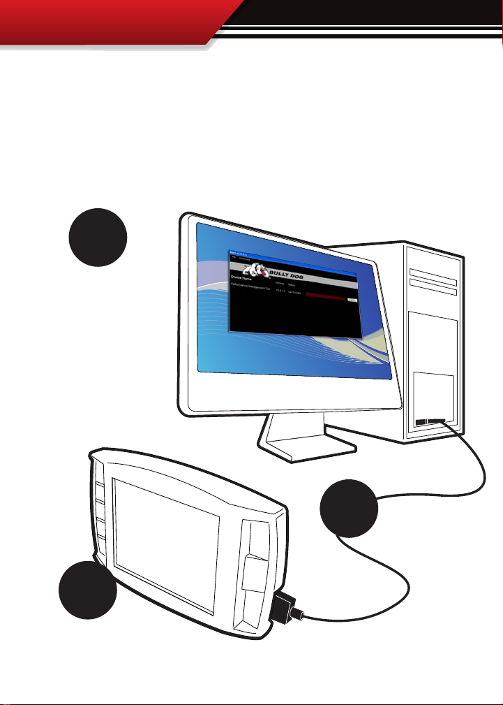
REMEMBER TO UPDATE!
Always update the Watchdog before installing on a vehicle using our Update Agent
internet update software. Visit www.bullydog.com to download the Update Agent
and get installation instructions for the Update Agent. The diagram below shows just
how easy it is to update any of our electronic products. For detailed update instructions
check the internet update instructions in Part 3 of your owners manual.
3.
Use the Update Agent
to update the Watchdog
software before installation on any vehicle.
This will ensure that the
Watchdog has the latest
programming available
from Bully Dog.
2.
Plug the USB cable
into a PC that has
the Bully Dog Internet
Update software: The
Update Agent.
1.
Plug in the Watchdog
to the USB Cable. SD card
must be installed in the Watchdog.
2
Page 3
INSTALLATION
INTRODUCTION
Congratulations on purchasing the Watchdog. This is one of the most technologically advanced
vehicle monitoring devices available in the market place. The Watchdog includes our patent
pending feature called the Driving Coach which assists users in maximizing driving eciency.
Using the Driving Coach feature end users can see improvements in fuel economy that will
completely oset the cost of the Watchdog itself.
This product is a relatively easy product to install, if installation assistance is required this product can be installed by any Bully Dog dealer and can also be installed using the assistance of
our technical support team.
At any time during installation and for operating or updating questions please call our technical support line: (866)-285-5936.
For other information visit our web site: www.bullydog.com
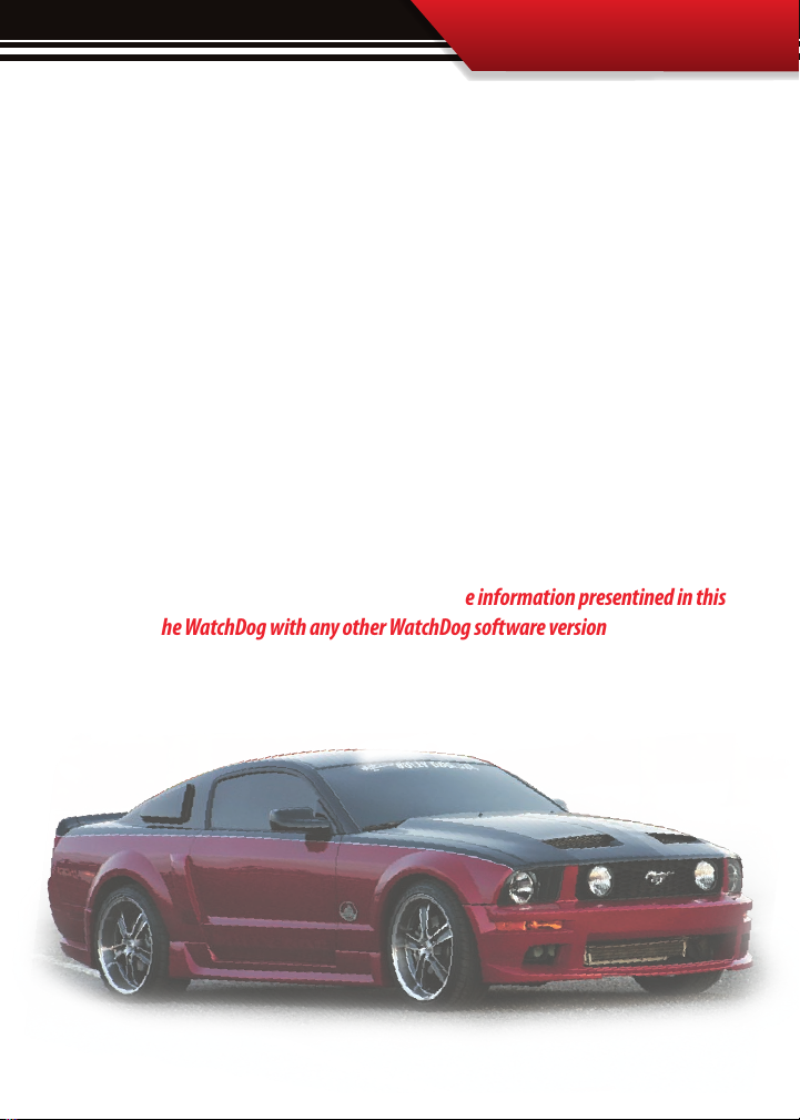
This instruction set has been written for WatchDog software version 1.1.0.3. There
may exist, distinct operating dierences between the information presentined in this
manual and the WatchDog with any other WatchDog software version
The WatchDog works with
most ‘96 & newer vehicles
3
Page 4

INSTALLATION
PART 1
Physical Installation
PHYSICAL INSTALLATION ............................................................................PGS. 515
SECTION 1: Parts Included ................................................................................. PG.5
SECTION 2: Parts Description .........................................................................PGS. 69
Watchdog Head Unit .......................................................................................pg. 6
OBDII Adapter Plug .........................................................................................pg. 7
Main Wiring Harness .......................................................................................pg. 8
Power Wire .....................................................................................................pg. 8
Micro SD Card ..................................................................................................pg. 9
Universal Windshield Mount ............................................................................pg. 9
Mini USB Cable ................................................................................................pg. 9
SECTION 3: Installation Overview ...................................................................... PG.10
SECTION 4: Installation .............................................................................. PG.1115
Part 1: Connecting the OBDII Adapter to the OBDII Port ..................................pg. 12
Part 2: Connecting the Power Wire .................................................................pg. 13
Part 3: Running the Main Wire Harness ..........................................................pg. 14
Part 4: Mounting the Watchdog using the windshield mount ......................... pg.15
4
Page 5
INSTALLATION
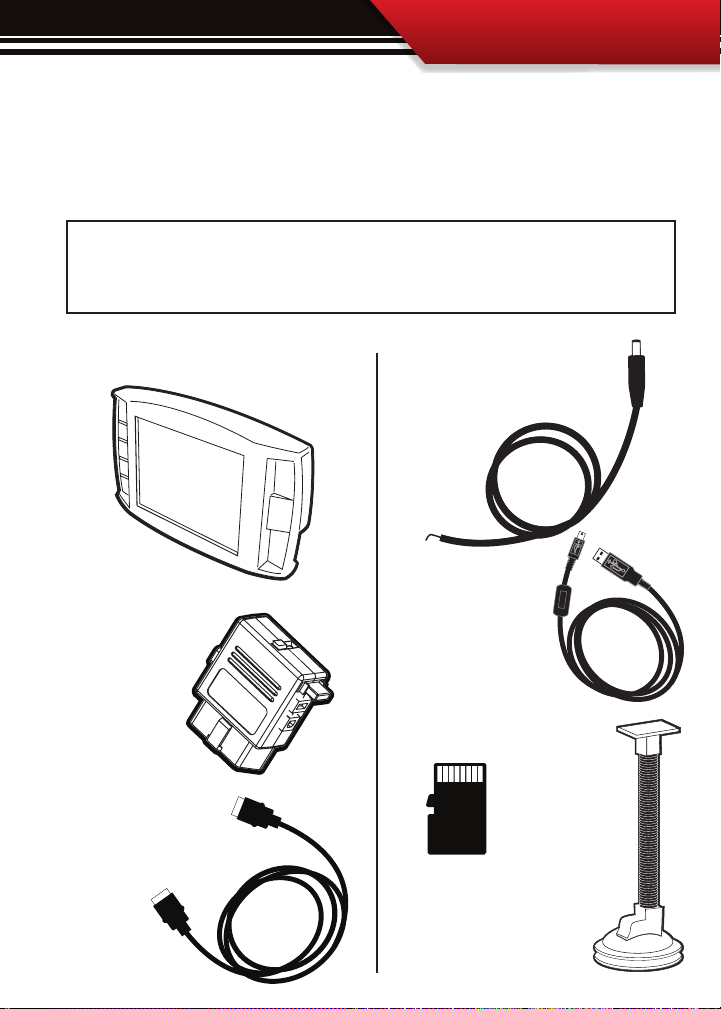
SECTION 1: Parts Included
The list below includes the major parts included in your Watchdog package. The tools list
indicates all of the tools necessary to complete the Watchdog install.
TOOLS NEEDED
• Fuse Puller
• Voltage Meter (optional)
THE WATCHDOG HEAD UNIT
OBDII ADAPTER PLUG
MAIN WIRE HARNESS
EXTRA PARTS (optional)
• Fuse Jack
• Spade connector
THE POWER WIRE
MINI USB CABLE
MICRO SD CARD
WINDSHIELD MOUNT
5
Page 6
INSTALLATION
SECTION 2: Parts Description
This section describes each of the parts in the Parts List, each description provides a physical set of attributes and a purpose for each part.
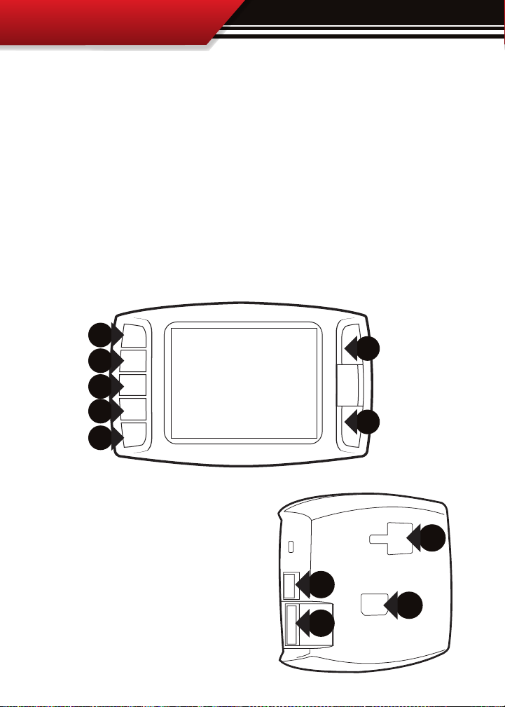
THE WATCHDOG HEAD UNIT:
The Head Unit is the interface through which all operating functions take place including:
Monitoring functions, the Driving Coach feature, and performance tests.
Watchdog Front Side: The Watchdog has seven capacitive touch buttons. Capacitive touch buttons are a
button style that is sensitive to the presence of your nger. Capacitive buttons do not need to be pushed,
only touched to activate. The Watchdog interface features a 2.4” LCD screen.
2.4” LCD
Watchdog Parts (Back side):
1. T-slot Mount Socket, this will work with a large range of
o the shelve mounting options.
2. Main harness port, elec tronic port for the main harness
with HDMI style plugs ends.
3. Micro SD Card Slot
4. Mini USB port
6
1
4
2
3
Page 7
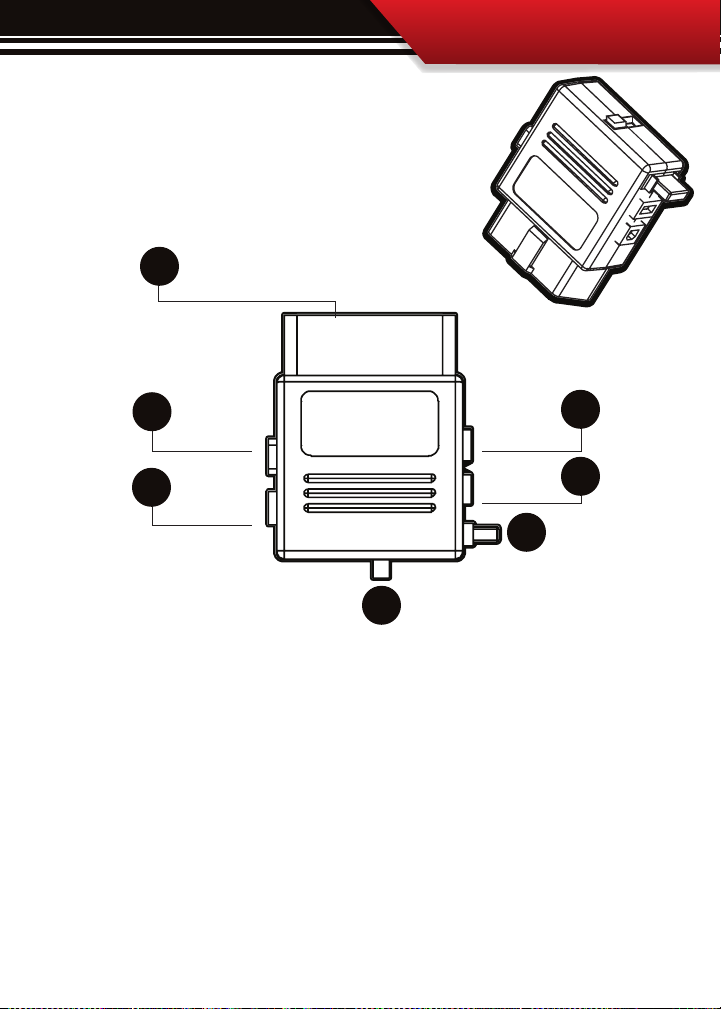
OBDII ADAPTER PLUG
The OBDII Adapter is a communication hub for the Watchdog.
The OBD ll Adaptor plugs directly into the vehicle OBD ll port. The
diagram below illustrates all of the OBDII parts and ports.
1
INSTALLATION
2
3
5
6
7
4
1. OBD ll Male End: this is the part of the adapter plug that plugs into the vehicle OBDll port.
2. Main Harness port: the main harness will plug into the Watchdog and into this port during installation.
3. Power wire port: the power wire will run from this port to the vehicle fuse pox during installation.
4. Power Supply Switch: use this switch to change power from running o of the Power Wire to OBD ll power
as a power supply for the Watchdog.
5. Four Pin USB: This port is used if a Bully Dog pyrometer kit is purchased for the Watchdog.
6. Five Pin USB
7. Adapter Plug 2 amp fuse, (do not unplug unless replacing)
7
Page 8
INSTALLATION
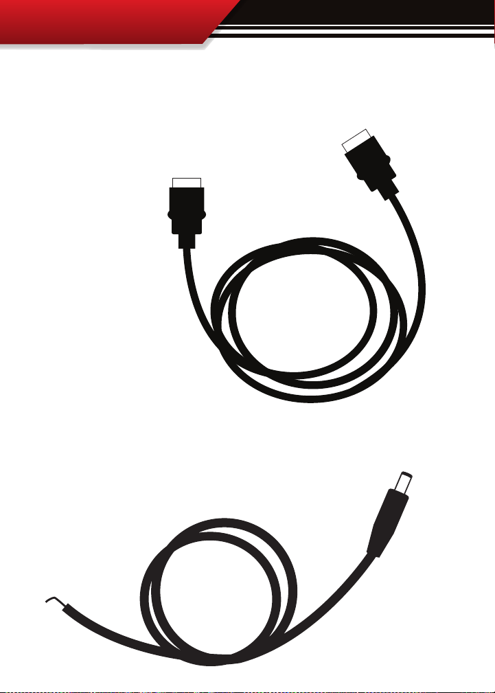
WATCHDOG MAIN WIRE HARNESS
The main harness connects the Watchdog to the OBD ll Adapter Plug and acts as the main line
of communication for the Watchdog. This harness is 5 ft in length.
POWER WIRE
The Power wire connects the OBD ll Adaptor Plug to the vehicle fuse box
to supply power to the Watchdog.
8
Page 9
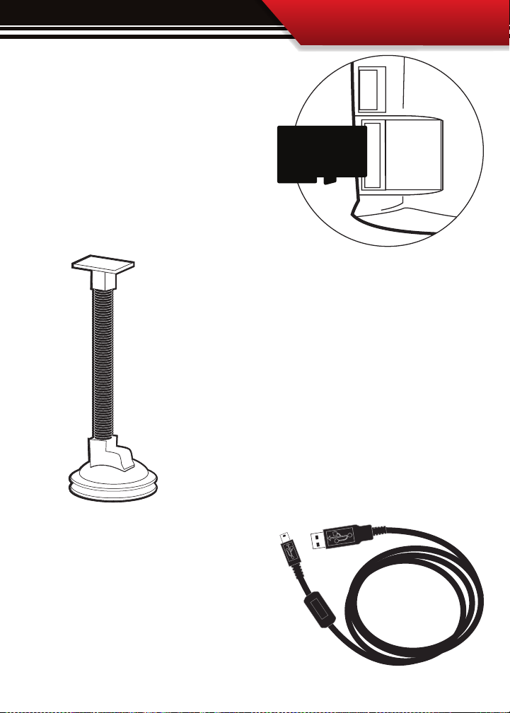
MICRO SD CARD
The Micro SD Card holds all of the electronic
les necessary to properly start up the
Watchdog, the SD card must be installed
into the micro SD card slot on the side of the
Watchdog at all times. The micro SD card
will even remain in the SD card slot during
internet updates.
UNIVERSAL WINDSHIELD MOUNT
This universal windshield mount is used to install the Watchdog rmly
onto the windshield, it is a suction cup mount that will work on any
vehicle windshield. We also oer a pillar pod mounting style, check our
web site for details.
INSTALLATION
MINI USB CABLE
The mini USB cable is a standard o the shelf mini
USB cable. It serves two purposes for the WatchDog:
1. Internet Updates
2. Downloading performance tests to a PC from the
WatchDog.
9
Page 10
INSTALLATION
Watchdog & Windshield Mount
OBDII Adapter Plug
OBDII Port
Power Wire
Fuse Box
Fire wall grommet
(optional)
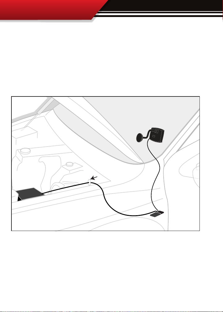
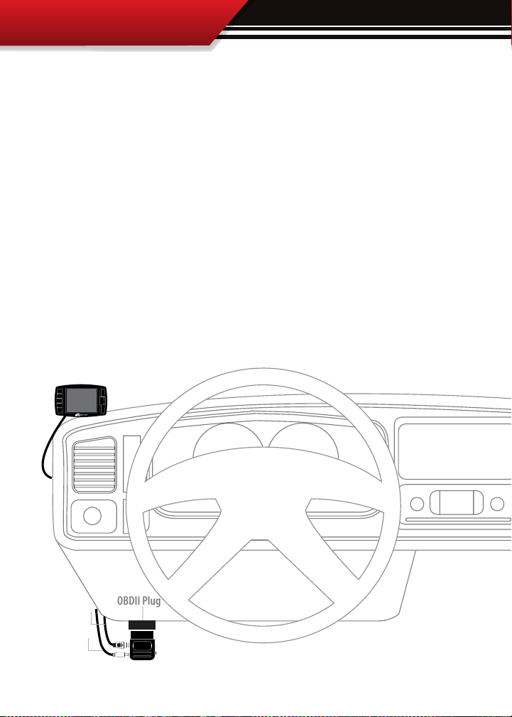
SECTION 3: Installation Overview
The installation overview diagram below illustrates a properly installed Watchdog. This
overview is meant to help reference the general location of installed parts and pieces of the
Watchdog. Note that some fuse boxes will be located inside the cab of the vehicle and will
not require that the power wire go through the vehicle fire wall. For ease of installation,
look for an in cab fuse box before going through the fire wall.
10
Page 11
INSTALLATION
SECTION 4: Installation
These installation instructions are split into four easy installation parts or activities. Each
part contains a small set of instructions to complete the part. Complete each part in order in
which they appear in this section for the easiest installation of this product. The installation
tasks start on the following page.
QUICK TIP: be sure that the switch on the OBD ll adapter plug is in the “down,” position. This will ensure
that the WatchDog is running o of power supplied from the power wire. The end result is that the Watch
Dog will only turn on when the ignition is turned on.
Reference “Notch” is up
Switch is down
11
Page 12
Possible OBDII Port Locations
(location may vary)
OBDII Plug
Main Cable
Power Wire
OBDII Adapter Plug Installation Diagram
GT
INSTALLATION
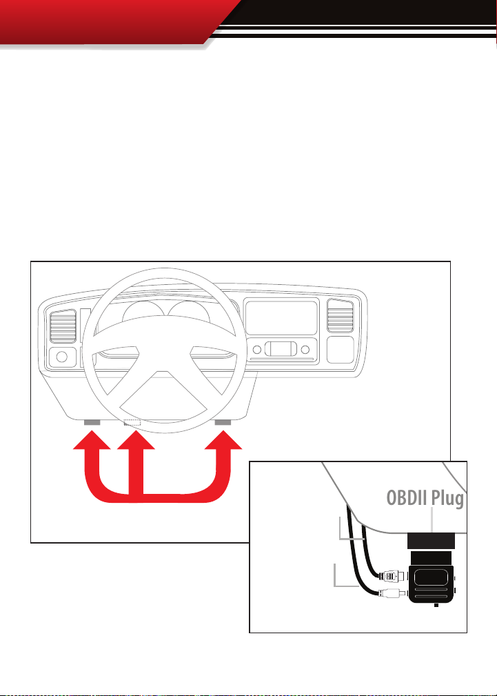
PART 1: CONNECT THE OBD ll ADAPTER TO THE VEHICLE OBD ll PORT
This part involves locating the vehicle’s OBD ll port and then simply plugging the OBD ll Adapter Plug
into the OBD ll port.
1. As the illustration below shows, OBD ll ports are always located somewhere under the drivers side
dash. The OBD ll port is a male receiver that will have the same shape as the end of the OBD ll Adaptor
plug.
2. Once the OBD ll port is located, then simply plug the OBD ll Adaptor plug into the OBD ll port.
12
Page 13
INSTALLATION
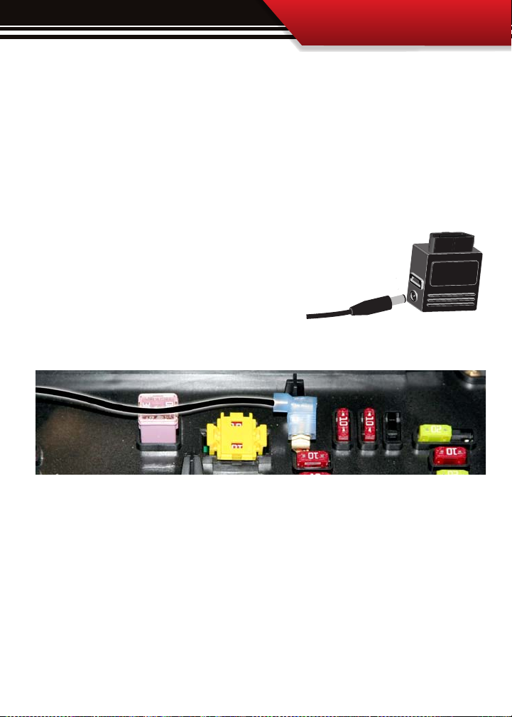
PART 2: INSTALLING THE POWER WIRE
Part 2 involves locating the correct fuse within the vehicle fuse box, and connecting the power wire
from the OBD ll Adaptor plug to the fuse in the fuse box.
Pre Installation: Locate the vehicle fuse box; the vehicle owners manual will indicate where the fuse box is
located within the vehicle. Open the fuse box and identify a fuse that has “key on power.” To identify the correct
fuse, nd an accessory fuse using the fuse diagram in the vehicle owners manual. If the vehicle manual does
not help identify an accessory fuse use a voltage meter to identify a fuse that supplies power only when the key
is in the on position.
Installation:
1. See the diagram to the right, simply plug the end of the power wire into the OBD
ll block before running the opposite end to fuse box.
Quick Tip: For the cleanest install of the power wire to a fuse
location use a spade connector and a fuse tap even though you
could just stu the Power wire into the fuse hole.
2. Run the end of the wire to the location of the fuse box. It may be necessary to go through the re wall to get
to the fuse box, if this is the case it may be easier to run through an existing grommet rather than drilling a new
hole.
3. Prepare the end of the power wire by attaching a spade connector to the end of the wire.
4. Remove the selected fuse from its location and then place a fuse tap that is made for that size of fuse
into that selected fuse location along with the original fuse.
5. Connect the spade connector to the end of the fuse tap.
6. Use zip ties to secure any loose wire left hanging from excess slack in the power wire.
13
Page 14
OBDII Plug
Main Cable
Power Wire
OBDII Adapter Plug Installation Diagram
Watchdog
INSTALLATION
INSTALLATION
PART 3: RUN WATCHDOG MAIN WIRE HARNESS
In this section you will connect the Watchdog Main Harness to the OBD ll Adaptor and then run
the other end of the main harness up the side of the vehicle dash and connect it to the back of
the Watchdog.
1. Plug one end of the Main Harness into the Main Harness port on the OBD ll adapter plug.
2. Run the other end of the harness up through the vehicle dash on the driver’s side so that the
end of the harness emerges from the dash near the vehicle A-pillar. It may be necessary to temporarily remove the vehicle weather stripping and dash panel to achieve an installation where
the Main Harness cannot be seen when the driver’s door is opened.
3. Plug the Main Harness into the back side of the Watchdog, make sure that there is enough
slack in the main harness to accommodate mounting the Watchdog.
14
Page 15
INSTALLATION
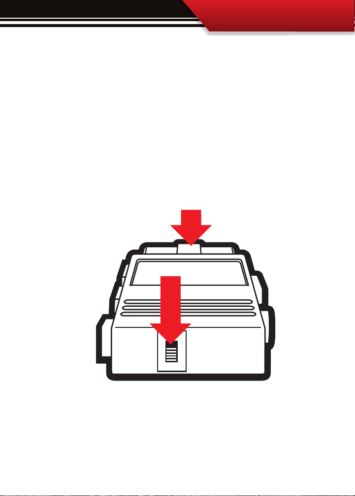
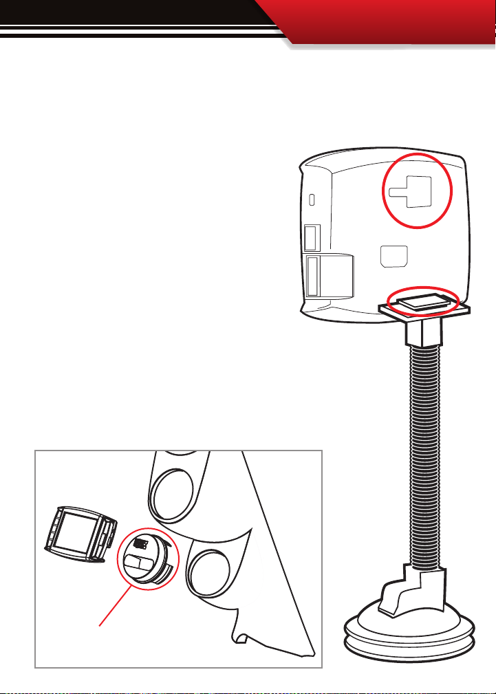
PART 4: MOUNTING THE WATCHDOG
The nal step to installation is mounting the Watchdog to the windshield using the universal
windshield mount.
1. Locate the T-shaped mount socket on the back side of
the Watchdog.
2. Notice that the top of the universal mount will t
into T-shaped socket and slide forward to secure the
Watchdog to the mount.
3. With the Watchdog connected to the mount use the
windshield mount to secure the Watchdog to the windshield. Be sure that the position of the Watchdog does
not obstruct the view of the road or distract the driver
from their primary responsibility, which is careful driving.
Also available is our 2 1/16” universal gauge mount.
Available on our website or through a Bully Dog Dealer.
PN: 30420
15
Page 16

OPERATION
PART 2
Operating Instructions
OPERATING INSTRUCTIONS ...................................................................... PGS. 1657
SECTION 1: Button Navigation ........................................................................................... pg. 18
SECTION 2: Setting up the WatchDog ...........................................................................pgs. 19-26
Part 1. Vehicle Setup Wizard..................................................................................................pgs. 19-22
Step 1: Detect Vehicle Protocol
Step 2: Choose Engine Displacement/Size
Step 3: Choose Vehicle Weight
Step 4: Choose Fuel Type ............................................................................................................................ pg. 21
Step 5: Choose Economy Goal
Step 6: Adjust Sensitivity Setting ............................................................................................................... pg. 21
Step 7: Turn the Driving Coach On or Off .................................................................................................... pg. 22
Step 8: Verify Settings
Step 9: Learning Instruction ....................................................................................................................... pg. 22
Part 2. Check Speed and Economy for accuracy
.................................................................................................................. pg. 20
................................................................................................. pg. 20
................................................................................................................... pg. 20
.................................................................................................................... pg. 21
................................................................................................................................ pg. 22
............................................................ pg. 23-26
SECTION 3: Exploring the Main Screen ..........................................................................pgs. 27-29
Parts of the Main Screen ..................................................................................................pg. 27
Four Button Functions of the Main Screen ........................................................................pg. 28
Large Gauge Style Options
SECTION 4: The Driving Coach ......................................................................................pgs. 20-33
Introduction .................................................................................................................... pg. 30
Activation
Proper setup
Interpreting the information
The Driving Coach Driving Tips
16
....................................................................................................................... pg. 30
................................................................................................................... pg. 30
...............................................................................................pg. 29
.....................................................................................pgs. 31-32
......................................................................................... pg. 33
Page 17

OPERATION
SECTION 5: Exploring the Main Menu & Sub Menus .......................................................pgs. 34-57
Gauge Setup .............................................................................................................. pg. 35-37
Performance Testing ................................................................................................... pg. 38-42
~ Performance Test ................................................................................................................................... pg. 39
~ 0-100kph Test ....................................................................................................................................... pg. 40
~ Performance Test Results ....................................................................................................................... pg. 41
~ Save Test Data to SD Card ...................................................................................................................... pg. 41
~Fastest Times .......................................................................................................................................... pg. 42
~ Performance Testing Setup .................................................................................................................... pg. 42
Driving Coach Setup ..................................................................................................pgs. 43-45
~ Display Driving Coach ............................................................................................................................ pg. 44
~ Set Economy Goal .................................................................................................................................. pg. 44
~ Reset Average Economy ......................................................................................................................... pg. 44
~ Adjust Acceleration ................................................................................................................................ pg. 45
~ Coach Sound Setup ................................................................................................................................ pg. 45
Vehicle Setup .............................................................................................................pg. 46-50
~Vehicle Setup Wizard .............................................................................................................................. pg. 47
~ Set Engine Size ....................................................................................................................................... pg. 47
~ Set Vehicle Weight ................................................................................................................................. pg. 48
~ Set Fuel Type .......................................................................................................................................... pg. 48
~Select Pyro Source ................................................................................................................................... pg. 48
~ Set Warning Levels ................................................................................................................................ pg. 49
~ Adjust Speed Display ............................................................................................................................. pg. 50
~ Adjust Economy Display ........................................................................................................................ pg. 50
User Options ..............................................................................................................pgs. 51-53
~ Color Theme Setup ................................................................................................................................. pg. 52
~ Backlight Setup ..................................................................................................................................... pg. 52
~ Animation Setup ................................................................................................................................... pg. 53
~ US/Metric units ..................................................................................................................................... pg. 53
~ Reset to Defaults .................................................................................................................................... pg. 53
Diagnostics ..................................................................................................................... pg. 54
Show Settings .................................................................................................................pg. 55
Update Software ....................................................................................................... pgs.56-57
17
Page 18
OPERATION
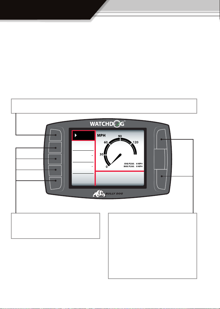
SECTION 1: Button Navigation
The buttons used on the Watchdog are Capacitive touch. Capacitive touch buttons only require
a touch on the button area rather than a push like regular buttons require. It is not necessary to
apply any significant force to the button while navigating through the various menus.
Press the top left button to enter the Main Menu, also use this button to exit menus.
Menu
RPM
rpm
00
Coolant
Intake
Economy
32
32
25
F
F
mpg
Press any of the four buttons on the left to
select items on the screen that are adjacent to
the button position.
18
While in the main screen, as is seen in the diagram above, these two buttons on the right side
of the WatchDog activate Day Mode and Night
Mode settings. Press the top button to activate
Day Mode and the bottom to activate Night
Mode. While in main menus and sub menus, in
general, these buttons work as up and down
buttons, they may also be used to select items
on the screen adjacent to these buttons.
Page 19
OPERATION
SECTION 2: Setting up the WatchDog (Very Important)
Proper setup of the WatchDog ensures that the accuracy of the information displayed by the
WatchDog will be reliable. This section is split into two different parts, these two different parts
should be performed in the order in which they appear in this manual to achieve proper setup.
The two parts involved are: Part 1 The Vehicle Setup Wizard, and Part 2 Checking vehicle Speed
and Economy read outs for accuracy.
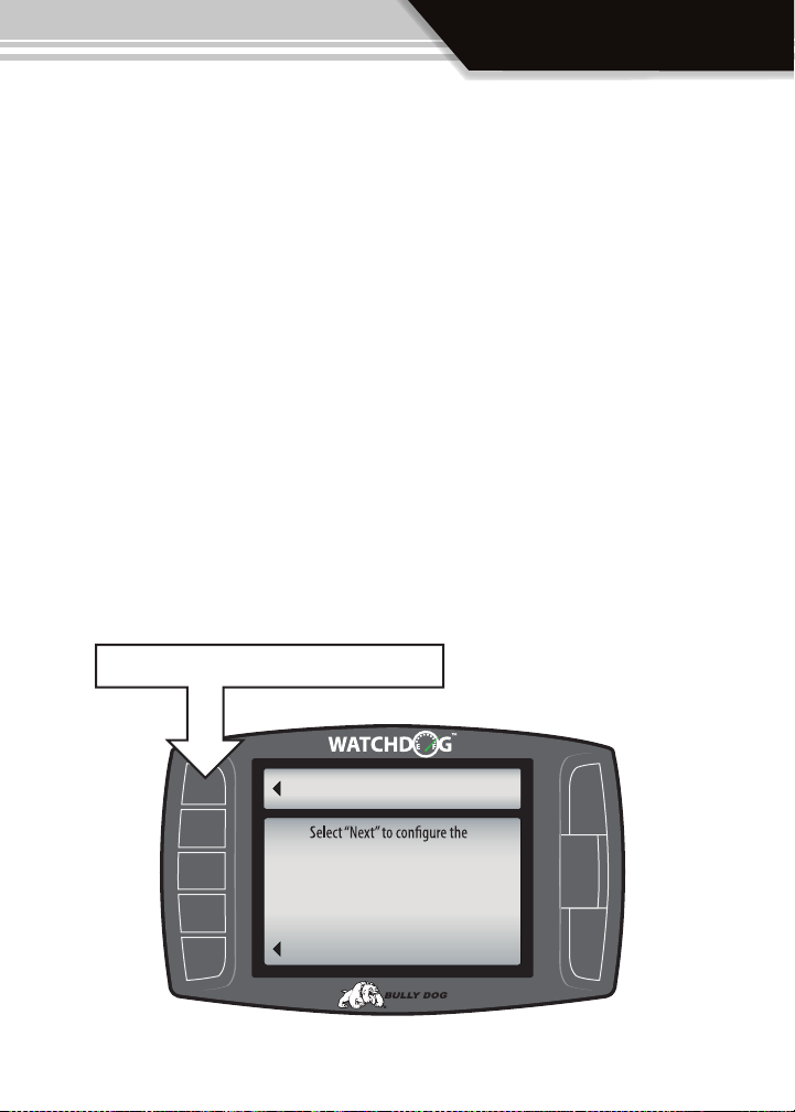
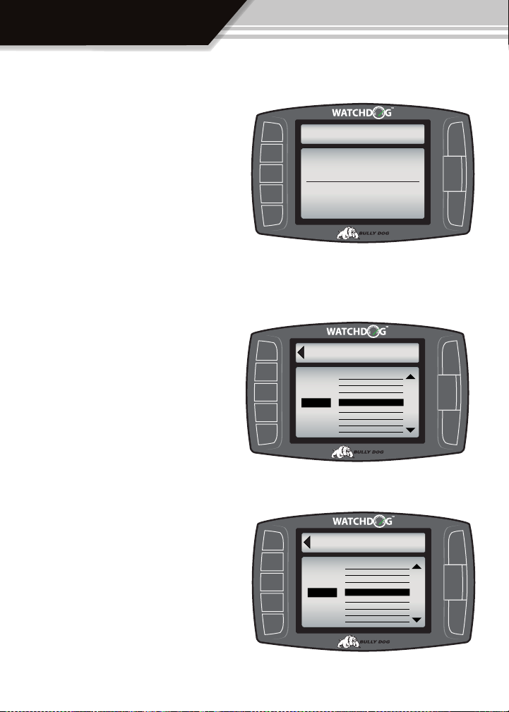
PART 1: VEHICLE SETUP WIZARD AUTO STARTUP, 9 STEPS
The vehicle setup wizard will appear on the WatchDog screen automatically upon initial use of
the WatchDog and subsequently every time the software version is updated. The diagram below shows an example of the Setup Wizard welcome screen, when this screen appears press the
“Next,” button to begin or press the “Exit,” button to perform the Setup Wizard at a later time.
The Setup Wizard involves nine easy steps that take less than ve minutes to complete.
While performing the Setup Wizard the vehicle’s engine should be on and running.
To begin the Setup Wizard press the “Next,” button.
Next
WatchDog for your vehicle.
Make sure the WachDog is connected to
the vehicle’s OBDII port and turn the
key to the RUN position.
Exit
SETUP WIZARD
19
Page 20
OPERATION
STEP 1: Detect Vehicle Protocol (auto function):
Once the Vehicle Setup Wizard begins it will automatically detect the vehicles communication
protocol. The WatchDog will not be able to detect
vehicle protocol on some vehicles if the engine is
not running.
Special Note: If an error screen appears while the
WatchDog is detecting the communication protocol it means that the WatchDog is not installed
properly or the engine needs to be turned on. See
the appendix for further detail.
STEP 2: ENGINE Size:
Choose engine size or displacement in liters, refer
to vehicle owners manual or the engine information sticker located near the top of the radiator
and fan.
CONNECT TO VEHICLE
The WatchDog is determining the
communication protocol used by
your vehicles ECM.
Connecting to vehicle:
Next
Select engine
displacement
Engine Sizes
4.2L
ENGINE SIZE
Engine Sizes
3.9
4.0
4.1
4.2
4.3
4.4
4.5
4.6
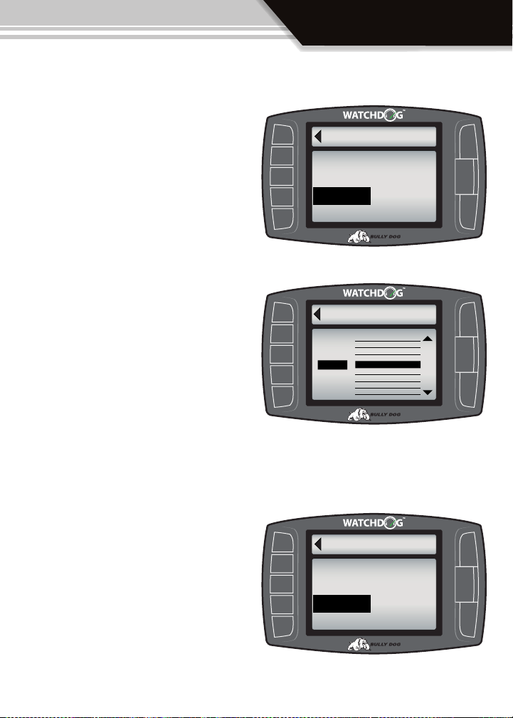
Step 3: Choose curb weight of vehicle
The curb weight of a vehicle is usually posted on a
sticker on the inside of the drivers door jam. If the
curb weight cannot be found on the door jam, refer
to the vehicle owners manual or look for the curb
weight on the internet. The vehicle can also be
weighed on a vehicle scale.
20
Next
Select engine
displacement
Selected
7100 lbs
Pounds
SET WEIGHT
6,800 lbs
6,900 lbs
7,000 lbs
7,100 lbs
7,200 lbs
7,300 lbs
7,400 lbs
7,500 lbs
Page 21
Step 4: Select vehicle fuel type
In step four simply select the vehicle fuel type, gasoline or diesel, and then press “Next,” to continue.
Step 5: Choose Economy Goal:
Choose the desired fuel economy goal. The Driving
Coach uses this goal to help determine if you are
meeting your fuel economy goals. It will compare
your average economy and Trip economy to your
goal to help determine your Average Grade and
your Trip Grade. Try choosing a reasonable goal to
start and then choose a more dicult goal “down
the road,” as you improve your personal driving
skill.
FUEL TYPE
Next
Select your vehicle’s fuel type.
GASOLINE
DIESEL
Next
Select a fuel economy
Economy
goal
Selected:
20 MPG
OPERATION
ECONOMY GOAL
17 mpg
18mpg
19mpg
20 mpg
21mpg
22mpg
23mpg
24mpg
Step 6: Adjust Sensitivity Setting
The sensitivity setting determines the degree to
which the Acceleration and Deceleration bar on the
Driving Coach interface react to actual vehicle acceleration and deceleration.
A new user will want to start with a low or medium
sensitivity setting and work up from there as their
driving improves and they are able to hold a high
letter grade for average and trip economy.
SENSITIVITY
Next
Adjust Accel/Decel Sensitivity.
LOW
MEDIUM
HIGH
21
Page 22

OPERATION
Step 7: Turn the Driving Coach on or off
The Driving Coach can only be displayed on the
main screen if it is turned on either during the Vehicle Setup Wizard or by entering the Driving Coach
Setup menu. In this step select whether you want
the Driving Coach On or O after nishing the Vehicle Setup Wizard.
Step 8: Verify settings/ setup complete
In this step the Watchdog displays the options you
have selected in the previous steps. Simply verify
that the information is correct by Selecting “Yes,” or
Select “No,” to restart the Vehicle Setup Wizard.
Next
Turn the Driving Coach Display On or
OFF by making your selection below.
Driving Coach ON
Driving Coach OFF
Yes
Accept Settings
Engine Size: 5.7Liters
Fuel Type: Gasoline
Econ Goal: 20 mpg
Accel/Decel: Medium Sensitivity
No
Start Over
DISPLAY COACH
SETUP WIZARD
Are these settings correct?
Step 9: Load Learning Instructions
Carefully read the on screen instructions before ex-
Exit
iting the Vehicle Setup Wizard. Once you have read
the on screen instruction, which is also displayed in
this screen to the right, exit into the WatchDog Main
Screen.
Special Note: Do not make any changes to the
LEARNING
The WatchDog is must ‘learn’ the
correct ranges of THROTTLE
and LOAD for your vehicle.
When it is safe to do so accelerate at
full throttle for several seconds to tlearn
the throttle and load ranges.
WatchDog before performing step 9
The WatchDog is waiting to obser ve 2-3 seconds of
full throttle, changing parameters before performing this step may interrupt the process and result in
inaccurate readings. To successfully perform this test nd a safe setting and time to run your vehicle
at full throttle for 2-3 seconds and do so when convenient. Once this step is complete move on to part
2, testing for speed accuracy, of the WatchDog Setup.
22
Page 23

OPERATION
Part 2: Check Speed and Fuel Economy Accuracy
The accuracy of the speed read out and fuel economy read out are two items that can be
adjusted within the WatchDog menu system. It is important that these two parameters are
accurate for most of the information output by the WatchDog and the Driving Coach to be
reliable. Follow the easy steps below to check and adjust these two important parameters.
Checking WatchDog Speed Read out Accuracy:
1. Make sure that speed is displayed in one of the four gauge locations along the left side of the
WatchDog while viewing the Main Screen. If Speed is not displayed then simply enter into the Gauge
Setup menu and highlight speed for any one of the four gauge locations.
2. With speed displayed on the Main Screen prepare to go out on the road and perform a speed test.
There are two reliable ways to test for speed accuracy: Method 1 is using a GPS and Method 2 is using
a stop watch.
Method 1 GPS: Use a GPS device to compare the speed displayed on the GPS device with the speed
that was displayed on the WatchDog at the same time. At any one time, if the speed displayed on the
WatchDog is more than 1 mph dierent than the GPS device then the WatchDog should be adjusted,
but rst, calculate the percent dierence plus or minus.
To calculate the percent dierence use this formula:
Percent dierence =
WatchDog speed - GPS Speed
GPS Speed
Example 1: A GPS device reads 65 mph and the Watch Dog reads 62 mph at a single moment
1. Percent dierence =
2. Percent dierence =
3. Percent dierence =
Once you have your answer move to step 3.
-.046 or -4.6% then round up to -5%
62 - 65
65
-3
65
23
Page 24

OPERATION
Method 2 Stop Watch: Use a Stop Watch to measure how long it takes to travel one mile while trav-
eling at 60 mph according to the WatchDog. To perform this method accelerate up to a speed of 60
mph according to the WatchDog and then set the vehicle speed control at that speed. While traveling
at that constant speed record the amount of time in seconds that it takes to travel exactly one mile.
Use highway mile markers to ensure that your one mile measurement is correct. If it takes 60 seconds
to travel one mile at a speed of 60 mph then the WatchDog is reading accurately. If it takes at least 2
seconds more or less than 60 seconds then you will want to record that dierence and use the formula
below to calculate the percent dierence before moving to step 3.
To calculate the percent dierence use this formula:
Percent dierence =
Example 1: Using a stop watch the actual time it took to drive one mile while traveling at 60 mph
according the WatchDog was 63 seconds.
1. Percent dierence =
2. Percent dierence =
Recorded Time - 60 seconds
60 seconds
63 - 60
60
3
60
3. Percent dierence =
Once you have your answer move on to step 3.
3. If the WatchDog is reading accurately according to either method then there is no need to adjust
the WatchDog speed display. If the WatchDog reads inaccurately then you will want to adjust the
speed display. To adjust speed for an inaccurate read out on the WatchDog enter the Main Menu
then navigate to the Vehicle Setup menu and enter into the Adjust Speed Display menu.
Once in the Speed Display menu adjust the speed by the exact opposite percent dierence that you
calculated to correct the WatchDog’s speed. So if the percent dierence was equal to 5.0% then adjust
the Speed Display to -5.0% to counterbalance the eect of the 5.0% inaccuracy. See the diagram on
the next page that illustrates the dierence.
24
.05 or 5.0%
Page 25

OPERATION
3 continued. The diagram below illustrates the Adjust Speed Display menu, on the screen is an example of how to make an adjustment for a percent dierence of 5.0% that was calculated using
either the GPS method or the Stop Watch method.
Go Back
to Vehicle Setup
Select the percentage
to adjust speed by.
Selected:
-5%
SPEED DISPLAY
Adjustment %
-8%
-7%
-6%
-5 %
-4%
-3%
-2%
-1%
Checking WatchDog Fuel Economy Read out Accuracy:
The actual fuel economy of a vehicle changes all the time, it is important to check the accuracy of the
average economy readout on the WatchDog at least once every changing season. Just to illustrate one
example of why fuel economy needs to be adjusted: did you know that fuel delivered to gas stations
during the winter months on average contains 1.3% less energy than in warmer seasons. That means
the same amount of liquid is going into the tank, but it is 1.3% less aective, on average. There are
many outside factors like this that you don’t control and the WatchDog doesn’t know the dierence
so that’s why it is important to adjust the fuel economy of the WatchDog every once in a while. Follow
the Steps in this section to adjust the Watch Dog Fuel Economy Read Out.
1. Go to the gas station and get a full tank of gas.
2. Before you start driving again reset the WatchDog’s average economy and rest your vehicles trip
odometer. Keep in mind that if the vehicles speedometer is o then the odometer will also be o. You
will need to be able to calculate the exact amount of miles driven before your next rell.
3. Drive the vehicle for an entire tank or two and then calculate your vehicles fuel economy by hand
which is simply miles driven divided by the gallons used to ll the tank back up.
25
Page 26

OPERATION
4. Now compare your calculated fuel economy to the average economy readout on the WatchDog’s
Driving Coach. Are they the same? If they are dierent use the formula below to calculate the percent
dierence so that the fuel economy readout on the WatchDog can be adjusted. If they are the same or
within 2% of each other then adjusting the fuel economy readout is pretty trivial.
To calculate the percent dierence use this formula:
Percent dierence =
Example 1: Assume the WatchDog Average Economy is 24 mpg and the Calculated Economy is 21.
WatchDog Average Economy - Calculated Average Economy
Calculated Average Economy
1. Percent dierence =
24 - 21
21
2. Percent dierence =
3
21
3. Percent dierence =
.142 or 14.2% round down to 14%
5. Once a percent dierence has been calculated and it is signicant as in the example above the
WatchDog fuel economy read out can be accurately adjusted. To adjust economy for an inaccurate
read out on the WatchDog enter the Main Menu then navigate to the Vehicle Setup menu and
enter into the Adjust Economy Display menu. The diagram below illustrates the Adjust Economy
Display menu, on the screen is an example of how to make an adjustment for a percent dierence
of 14.0%.
Go Back
to Vehicle Setup
Select the percentage
to adjust economy by.
Selected:
-14%
ECON DISPLAY
Adjustment %
-17%
-16%
-15%
-14%
-13%
-12%
-11%
-10%
26
Page 27

OPERATION
SECTION 3: Exploring the Main Screen
The Main Screen is the screen that displays vehicle ac tivity, it is also the screen from which the
main menu is accessed. The Main Screen has a multitude of different functions; the diagrams
in this section fully explain each function accessed from the Main Screen. The first diagram displayed names all the parts of the Main Screen.
Parts of the Main Screen:
The Diagram directly below describes all of the on screen parts of the Main Screen.
Menu button: press to enter the main menu.
Menu
RPM
00
Coolant
32
Intake
32
Economy
25
Vehicle parameters: To change which
vehicle parameter is displayed in the
large gauge area simply press one of
the four buttons next the preferred
vehicle parameter.
rpm
Large
F
F
mpg
Gauge
Area
Large Gauge Area: The large gauge area can
display an expanded version of a vehicle
parameter or it will display the Driving
Coach if the driving coach has been turned
on from inside the menu system.
27
Page 28

OPERATION
Four Button Functions of the Main Screen:
The diagram below shows the main four functions performed on the main screen.
FUNC TION 1: Press the top left button to enter the Main Menu, also use this button to exit menus.
Menu
RPM
rpm
00
Coolant
F
32
Intake
F
32
Economy
mpg
25
FUNCTION 2: Press any of the four buttons on
the left side of the Watchdog adjacent to one of
the vehicle parameters on the screen, and that
vehicle parameter will then display in the large
gauge area. This function will only work if the
Driving Coach is turned o.
FUNCTION 3: Continuously holding any of the
four buttons identied above, while the Driving
Coach is O, will change the gauge style that ap-
pears in the large gauge area for the vehicle parameter that is displayed next to the button that
is being touched. See the three dierent gauge
style options on the next page.
Large
Gauge
Area
FUNCTION 4: Press the top button to change the
screen theme into the Day Mode setting, press
the bottom button to switch to Night Mode.
28
Page 29

OPERATION
Large Gauge Styles:
The Large Gauge Area can display three dierent gauge styles. These gauge styles can be
displayed on the main screen. These gauge styles can only be used and viewed when the driving coach is not activated in which case it would be displayed on the main screen. Use Button
Function 3 while in the Main Screen to rotate through the dierent gauge styles.
Analog gauge with Average and Peak readings
RPM
Coolant
Intake
Economy
Menu
00
25
32
32
Large
rpm
Gauge
F
F
Area
mpg
Analog gauge with mini graph
29
Large Graph
Page 30

OPERATION
SECTION 4: The Driving Coach
The Driving Coach is a special feature designed to help a driver operate their vehicle more
efficiently. It coaches drivers into better driving habits by providing real time visual feedback and audio feedback as to how efficient they are driving.
DRIVING COACH ACTIVATION:
To display the Driving Coach on the Main
Screen, navigate into the “Display Driving
Coach,” menu.
Go Back
to Drv. Coach Setup
Turn the Driving Coach Display On or
OFF by making your selection below.
DISPLAY COACH
Main Menu > Driving Coach Setup > Display
Driving Coach > Driving Coach On or Off.
Driving Coach ON
Driving Coach OFF
DRIVING COACH AUDIO FEED BACK:
To turn the Driving coach audio feedback
on and o navigate into the, “ Sound Setup”, menu.
Main Menu > Driving Coach Setup > Sound
Setup > Sound On or O.
Go Back
to Drv. Coach Setup
Turn the Driving Coach Sound On or
OFF by making your selection below.
Coach Sound ON
Coach Sound OFF
COACH SOUND
PROPER SETUP VERY IMPORTANT
Before the driving coach will display accurate information it must be setup for the particular
vehicle in which it will be used. To achieve proper setup run though
Wizard) of the Operating Instructions.
Section 2 (Vehicle Setup
30
Page 31

OPERATION
Menu
Coolant
RPM
Intake
Economy
00
rpm
25
mpg
25
23
25
2138
B-
B
32
F
32
F
Wasted Energy
Dec. Acc.
Low
Average Mpg
Instant Mpg
Trip Mpg
Trip Grade
Gallons Grade
High
Menu
Coolant
RPM
Intake
Economy
00
rpm
25
mpg
25
23
25
2138
B-
B
32
F
32
F
Wasted Energy
Dec. Acc.
Low
Average Mpg
Instant Mpg
Trip Mpg
Trip Grade
Gallons Grade
High
THE DRIVING COACH DISPLAY DIAGRAMS:
The Large Gauge Area is where the Driving Coach information is displayed. The diagrams
below, and on the following page, illustrate the information that is collected and displayed
by the Driving Coach. There are four dierent Driving Coach diagrams below that will breakdown and describe the information displayed in the Driving Coach.
Diagram 1: Driving Coach Location
Wasted Energy
Dec. Acc.
Low
Average Mpg
23
Instant Mpg
25
Gallons Grade
2138
Trip Mpg
Trip Grade
High
B
25
B-
Diagram 2: Wasted Energy and Driving Efficiency Bars
Wasted Energy
Dec. Acc.
LowHigh
Driving Efficiency: This bar indicates a level of consistent driving, if a
driver varies between acceleration and deceleration frequently then
this bar will be negatively aected. Additionally heavy acceleration
and deceleration can have a very negative eect. This bar will help
a driver drive at more consistent speeds which will positively aect
their fuel economy.
The D riving Coach: The highlighted area on the WatchDog
screen represents the Driving
Coach information display. All
of the highlighted information
makes up the Driving Coach.
Wasted Energy: The waste energy graph, displays acceleration and deceleration. The center line of this graph represents
zero wasted energy. If a driver
accelerates too quickly or decelerates too quickly they will
see a bar extend outward from
zero indicating an amount of
energy wasted. The sensitivity
of the wasted energy bar can
be adjusted in the “Adjust Acceleration”, menu.
31
Page 32

OPERATION
Menu
Coolant
RPM
Intake
Economy
00
rpm
25
mpg
25
23
25
2138
B-
B
32
F
32
F
Wasted Energy
Dec. Acc.
Low
Average Mpg
Instant Mpg
Trip Mpg
Trip Grade
Gallons Grade
High
Menu
Coolant
RPM
Intake
Economy
00
rpm
25
mpg
25
23
25
2138
B-
B
32
F
32
F
Wasted Energy
Dec. Acc.
Low
Average Mpg
Instant Mpg
Trip Mpg
Trip Grade
Gallons Grade
High
Diagram 3: Average Mileage Line
Average MpgGallons Grade
23
Average MPG: This number represents overall
average economy. All driving activity continues
to accumulate and gets averaged into this number until it is reset. This number can only be reset
within the “Driving Coach Setup” menu.
Diagram 4: Instant economy and Trip Info
The Grade: This grade
is based on the drivers
overall average perfor-
2138
B
mance, this grade will
remain a cumulative
indicator of drivers performance until it is reset
by resetting “Average
Economy.”
Gallons: This number represents an estimated total
number of gallons used. This number will reset back
to zero if, “Average Economy,” is reset.
Instant Mpg
25
Instant Mpg: This number represents the calculated fuel economy for
a vehicle at an instantaneous point or moment in time. It can be used
as an instant indicator of driving performance.
Trip Mpg
Trip Grade
32
25
B-
Trip Mpg: This is a cumulative
average economy that resets
each time the WatchDog is
turned o.
Trip Grade: This is a cumulative grade that indicates driver
performance over a single trip.
This grade resets each time the
WatchDog is turned o.
Page 33

OPERATION
THE DRIVING COACH ON SCREEN DRIVING TIPS
While parked or after a period of idle the driving coach will post driving tips that will help
the driver improve their own driving eciency. The tips will appear based on drivers previous performance, they aren’t just randomly posted.
Econ Tip 1: Acceleration: Accelerate Gradually to save fuel
Econ Tip 2: Slowing/Stopping: Coast as long as possible and then brake smoothly
ECON TIP 3: Idling: Spend less time idling to save fuel
ECON TIP 4: Control Speed: Keep your speed steady to save fuel
ECON TIP 5: Speed Limit: Drive the speed limit or 5 to 10 MPH slower to save fuel
ECON TIP 6: More Tips: For more Econ Tips visit: www.fueleconomy.gov
ECON TIP 7: Econ Goal: Set a more achievable fuel economy goal
ECON TIP 8: Econ Goal: Consider increasing your fuel economy goal
Econ Tip 9: Idle Time: Idling wastes fuel. Shut o your engine when possible
33
Page 34

OPERATION
SECTION 5: Exploring the Main Menu and submenu systems
The diagram below shows all of the main menu items. Section 5 includes a diagram and a
comprehensive description of each ain menu item and all sub menus.
Go Back
to General Disp
Gauge Setup
Performance Testing
Driving Coach Setup
Vehicle Setup
User Options
Diagnostics
Show Settings
Update Software
MAIN MENU
34
Page 35

OPERATION
GAUGE SETUP: PGS 3537
Enter the Gauge Setup menu to change the vehicle parameters (PIDs) displayed on the four
gauge locations in the Main Screen. See a complete list and description of all of the potential
displayable vehicle parameters on the following page.
Special Note: The WatchDog relies primarily on gathering vehicle information through the
OBD ll port. Earlier model year vehicles generally do not display as many vehicle parameters
as newer model vehicles. Technology advances in later model vehicles have brought more
vehicle sensors and so they are able to broadcast more vehicle parameters that the WatchDog can receive and display. As long as the WatchDog is properly connected to the vehicle,
while browsing the Gauge Setup menu, the WatchDog will only display those parameters
that are available for the vehicle it is installed on.
Notice that upon entering the gauge setup menu that, Set Gauge 1, is highlighted in black. When a gauge location
is selected it is highlighted in black on the left and it also appears above the vehicle parameter selection box.
Go Back
Speed
Set Gauge 1
Boost
Set Gauge 2
RPM
Set Gauge 3
Coolant
Set Gauge 4
To highlight a dierent gauge location to change
the parameter in that gauge location press the selection button that coincides with that gauge location. For example select gauge location 1, press the
second button down on the left side of the Watchdog. Once the desired gauge location is highlighted
you can scroll through vehicle parameters to set
the desired parameter in that location.
GAUGE SETUP
Gauge 1
Use the Up & Down Arrows
to change the gauge function.
Pyro 2
Speed
Boost
Use the large Up Down Buttons to highlight a
particular vehicle parameter for any of the gauge
locations.
35
Page 36

OPERATION
Vehicle Parameters:
The list of vehicle parameters below, which also extends onto the next page shows vehicle parameters
which can potentially be displayed on the Watchdog. Due to vehicle specic availability not all of the
parameters displayed below will be available on every vehicle and some vehicles will have signicantly
fewer parameters which can be viewed. Only the parameters that are available for a particular vehicle
will show up in the Gauge Setup menu once the WatchDog has been fully installed.
• Pyro 1 and Pyro 2: These gauge options will display EGTs or exhaust gas temperatures. What is dis-
played on the main screen of the WatchDog actually depends on the “Pyro Source,” that is selected from
the “Select Pyro Source,” menu which is in the Vehicle Setup Menu.
Special Note: Some diesel and gas vehicles have OEM temperature sensors in their exhaust systems
which will display their temperature reading in the pyro 1 and or pyro 2 locations as long as the “Pyro
Source,” is set to “Factory Pyros.” Within the Vehicle Setup menu is a menu item, “Select Pyro Source,”
that allows you to switch betwee n looking at OEM pyros and looking at an aftermarket Bully Dog
Pyrometer. The correct source must be selected to view the desired pyrometer source.
• Speed: Display the vehicle speed in either miles per hour or kilometers per hour depending on what
units of measurement has been selected.
Special Note: If speed is reading inaccurately then the speed displayed can be adjusted, read Section 2
of the operating instructions to find out how to correctly calibrate the speed display.
• Boost: Boost is a measure of pressure in lbs. that a vehicles turbo charger is generating. It is possible that
this parameter will also show a manifold pressure reading on non turbo charged vehicles.
• RPM: Revolutions per minute of the vehicles crank shaft.
• Coolant: Display coolant temperature in Fahrenheit or Celsius depending on what units of measure-
ment has been selected.
• Throttle: Display throttle position as a percentage where an idle position equals 0% and full throttle
equals 100%.
• Intake: Display the intake temperature at the point where the OEM temperature sensor is installed
within the air intake stream. Displays temperature in Fahrenheit or Celsius depending on what units of
measurement has been selected.
• Barometer: Display atmospheric pressure in PSI (pounds per square inch) or in KPA (kilopascals) de-
pending on what units of measurement has been selected.
36
Page 37

OPERATION
• Battery: Current battery output voltage in volts.
• Fuel Pressure: Display fuel rail pressure on most common rail fuel systems or just lift pressure on some
non-common rail fuel systems.
• Load: Display calculated engine load displayed as a percentage from 0% for no load to 100% for maxi-
mum load capacity.
• Timing: Display ignition timing on a gasoline fueled vehicle and injection timing on a diesel.
• MAF: Display mass air ow in grams per second. MAF is a measure of how much air is coming into the
air intake stream.
• Fuel Econ.: Display the vehicles instant fuel economy in miles per gallon or liters per 100 kilometers
depending on what units of measurement has been selected
Special Note: If Fuel Econ. is reading inaccurately then the economy dis played can be adjusted, read
Section 2 of the operating instructions to find out how to correctly calibrate the Fuel Econ. display.
• Fuel Flow: Display a calculated amount of instant fuel ow through the fuel system. Units will display in
gallons per hour or liters per hour depending on what units of measurement have been selected.
37
Page 38

OPERATION
PERFORMANCE TESTING: PGS 3842
Our performance testing feature is a great feature that oers drag racers the ability to record 1/4
mile runs. All of the performance testing information gathered can be transferred to a PC using
our Performance Testing Analysis Software. See the Appendix for information on the Performance Testing Analysis Software. Follow the next few pages for a detailed description of each
performance testing submenu.
Go Back
PERFORMANCE TEST
to Main Menu
Performance Test
0-100 Kph Test
Performance Tests Results
Save Test Data to SD card
Fastest Times
Performance Testing Setup
38
Page 39

OPERATION
Performance Test:
Selecting “Performance Test” will initiate a 1/4 mile test. The test will appear dierently based on the
type of Performance Testing style that is selected. There are two dierent types of performance tests
that can be ran. Those two types of the tests are displayed below. To select the preferred performance
test type select that in the Performance Testing Setup menu.
Special Note: This performance racing function should only be used on a sanctioned 1/4 mile
drag racing track. Street racing is illegal and extremely unsafe.
• Speed Sensitive Performance Test: Once initiated
this test type will instruct the end user to rst bring
the vehicle to a stop. Once the vehicle is at zero
miles per hour the WatchDog will instruct the driver
that the test will begin once the WatchDog detects
Speed.
• Race Tree Performance Test: Before initiating the
Race Tree style performance test it is important that
the vehicle should already be at a complete stop.
Once initiated the WatchDog will display a classic
drag race tree on the screen. As soon as the lights
on the drag race tree turn green the WatchDog will
begin to record the vehicles time. It will not wait to
detect speed before it starts recording.
• Results Screen: Once a complete 1/4 mile has been completed the WatchDog will display the results
screen. If the user wants to save the test so it can be displayed and analyzed on a PC then the run can be
saved to the SD card by immediately going to the Save Test To SD Card Menu.
Go Back
PERFORMANCE TEST
TEST STARTS
WHEN VEHICLES READS
SPEED
39
Page 40

OPERATION
0-100 KPH Test:
Selecting 0-100 KPH test will initiate a 0-100 kilometer per hour test which is the equivalent to about
62 miles per hour. This is a standard test that is popular in countries that measure distances in kilometers. The test will appear dierently based on the type of Performance Testing style that is selected.
There are two dierent types of performance tests that can be ran. Those two types of the tests are
displayed below. To select the preferred performance test type select that in the Performance Testing
Setup menu.
Special Note: This 0-100 KPH racing function should only be used on a sanctioned 1/4 mile
drag racing track. Street racing is illegal and extremely unsafe.
• Speed Sensitive Performance Test: Once
initiated this test type will instruct the end user to
rst bring the vehicle to a stop. Once the vehicle
is at zero kilometers per hour the WatchDog will
instruct the driver that the test will begin once the
WatchDog detects Speed.
Go Back
PERFORMANCE TEST
TEST STARTS
WHEN VEHICLES READS
SPEED
• Race Tree Performance Test: Before initiat-
ing the Race Tree style performance test it is
important that the vehicle should already be at a
complete stop. Once initiated the WatchDog will
display a classic drag race tree on the screen. As
soon as the lights on the drag race tree turn green
the WatchDog will begin to record the vehicles
time. It will not wait to detect speed before it
starts recording.
• Results Screen:
screen. If the user wants to save the test so it can be displayed and analyzed on a PC then the run can be
saved to the SD card by immediately going to the Save Test To SD Card Menu.
40
Once a complete 1/4 mile has been completed the WatchDog will display the results
Page 41

OPERATION
Performance Test Results:
View the results for the last performance test that was run.
Save Test Data to SD Card:
Save the results for the last run to the WatchDog SD Card. All runs that are saved to the SD Card can be
transferred to our Performance Testing Analysis software. For more information on our Performance
Testing Analysis software see the appendix of this manual or visit our website: www.bullydog.com.
Press “Yes,” to save the currently displayed run results
to the SD Card.
Press “No,” to exit the menu
without saving the run.
41
Page 42

OPERATION
Fastest Times:
View the results for the quickest 1/4 mile ever recorded.
Performance Testing Setup:
Choose the initiation method for a performance test. The two dierent types available are the Drag Tree
method and the Speed detection method. See descriptions below.
Use these two buttons to toggle
between Speed Sense and Race
Tree starting methods, press “Go
Back.” when finished.
42
Go Back
to Main Memu
Current:
SPEED SENSE
SPEED SENSE
RACE TREE
TEST START
Page 43

OPERATION
DRIVING COACH SETUP: PGS 4345
This is the menu where modications for the Driving Coach can be made that will directly
eect the way the driving coach behaves. Read section 2 of the operating instructions
to nd out how to completely setup the WatchDog and the Driving Coach. The next two
pages will describe the function for each of the menu items listed in the diagram below.
Go Back
to Main Menu
Display Driving Coach
Set Economy Goal
Reset Average Economy
Adjust Acceleration
Coach Sound Setup
COACH SETUP
43
Page 44

OPERATION
Display Driving Coach:
Turning the Driving Coach On or O will determine whether the Driving Coach is displayed in
the large Gauge Area in the Main Screen of the
WatchDog.
Go Back
to Drv. Coach Setup
Turn the Driving Coach Display On or
OFF by making your selection below.
DISPLAY COACH
Use these two buttons to toggle between
on and off, press “Go Back.” when finished.
Driving Coach ON
Driving Coach OFF
Set Economy Goal:
If the current economy goal that is set in the Driving Coach is resulting with Grades that are too high
or too low the economy goal can be adjusted within this menu. It is important to set an economy
goal that is reasonable for the type of vehicle and the typically expected driving conditions.
Press the “Go Back”
button when the
desired goal has
been highlighted.
Go Back
to Drv. Coach Setup
Select a fuel economy
goal
Selected:
20 MPG
ECONOMY GOAL
Economy
17 mpg
18mpg
19mpg
20 mpg
21mpg
22mpg
23mpg
24mpg
Scroll up or down
using the indicated
buttons to highlight the desired
goal.
Reset Average Economy:
The Average Economy readout, the Gallons
readout, and the Average grade readout can
all be reset in this menu. Note that by resetting it will reset all three parameters.
44
Page 45

OPERATION
Adjust Acceleration:
The sensitivity setting determines the degree to which the Acceleration and Deceleration bar on the
Driving Coach interface react to actual vehicle acceleration and deceleration.
A new user will want to start with a low or medium sensitivity setting and work up from there as
their driving improves and they are able to hold a high letter grade for average and trip economy.
• Recommended Sensitivity Selections: Not quite sure which setting to use, try the recomended
uses below until you become comfortable and condent with using the settings under more challenging conditions.
Low Setting: City Driving and beginners in any driving circumstances.
Med Setting: Rural for beginners and some city driving for more advanced users.
High Setting: Rural Only.
Press the “Go Back” button when the desired
sensitivity level has been highlighted.
Use these two buttons to toggle between
Low, Medium, High sensitivity levels.
Coach sound setup:
The Audio feedback provided by the Driving
Coach can be turned On or O. This only aects
the sound feedback provided by the Driving
Coach, it does not aect button feedback or
vehicle warnings.
Use these two buttons to toggle between
On and Off, press “Go Back.” when finished.
Go Back
SENSITIVITY
to Drv. Coach Setup
Adjust Accel/Decel Sensitivity.
LOW
MEDIUM
HIGH
Go Back
to Drv. Coach Setup
Turn the Driving Coach Sound On or
OFF by making your selection below.
Coach Sound ON
Coach Sound OFF
COACH SOUND
45
Page 46

OPERATION
VEHICLE SETUP: PGS 4650
This menu includes everything related directly to the vehicle, mostly making up input points
for vehicle information to make sure the WatchDog knows what it is running on. This menu
also includes the Vehicle Setup Wizard and the Speed and Economy Adjustment menus.
Go Back
to Main Menu
Vehicle Setup Wizard
Set Engine Size
Set Vehicle Weight
Set Fuel Type
Select Pyro Source
Set Warning Levels
Adjust Speed Display
Adjust Economy Display
VEHICLE SETUP
46
Page 47

OPERATION
Vehicle Setup wizard
The Vehicle Setup Wizard appears the very rst time the WatchDog is setup. The Setup Wizard can
be activated at any time by entering this menu. The Setup Wizard process is described in detail in
section 2 of the operation part of the manual.
Press the “Next” button to start the
Setup Wizard.
Hint: This option is very useful if the
WatchDog is ever transferred to a new
vehicle.
Next
Make sure the WachDog is connected to
the vehicle’s OBDII port and turn the
Exit
SETUP WIZARD
WatchDog for your vehicle.
key to the RUN position.
Set Engine Size (Displacement)
Choose a correct engine size (displacement) in liters for the vehicle that the WatchDog is installed
on. Refer to vehicle owners manual or the engine information sticker located near the top of the
radiator and fan to nd the correct size (displacement) for the vehicle.
Press the “Go Back”
button when the
correct size has
been highlighted.
Go Back
to Vehicle Setup
Select engine
displacement
Engine Sizes
4.2L
ENGINE SIZE
Engine Sizes
Scroll up or down
3.9
4.0
4.1
4.2
4.3
4.4
4.5
4.6
using the indicated
buttons to highlight the correct
engine size.
47
Page 48

OPERATION
Set Vehicle weight
Choosing the correct vehicle weight will help the WatchDog to provide accurate information for that
vehicle application.
The curb weight of a vehicle is usually posted on a sticker on the inside of the drivers door jam. If the
curb weight cannot be found on the door jam, refer to the vehicle owners manual or look for it on
the internet. The vehicle can also be weighed on a vehicle scale.
Press the “Go Back”
button when the
correct vehicle
weight has been
highlighted.
Go Back
to Vehicle Setup
Select engine
displacement
Selected
7100 lbs
Pounds
Set Fuel Type
Set or change the fuel type in accordance with the
fuel used in the vehicle. The WatchDog will not behave correctly if the correct fuel type is not selected.
Use these two buttons to toggle between gasoline
or diesel, press “Go Back,” when finished.
Select Pyro Source
Choose between attempting to pickup a stock
exhaust temperature sensor (OEM), or using a Bully
Dog pyrometer.
SET WEIGHT
6,800 lbs
6,900 lbs
7,000 lbs
7,100 lbs
7,200 lbs
7,300 lbs
7,400 lbs
7,500 lbs
Go Back
FUEL TYPE
to Vehicle Setup
Select your vehicle’s fuel type.
GASOLINE
DIESEL
Scroll up or down
using the indicated
buttons to highlight the correct
vehicle weight.
Use these two buttons to toggle between gasoline
or diesel, press “Go Back,” when finished.
48
Page 49

OPERATION
Set Warning Levels
This very impor tant feature will trigger an audio and visual warning on the WatchDog main screen
during normal operation if a set warning level breaches the user set levels. The two diagrams below
describe the process of setting up a warning level.
Press the button next to the Warning Parameter to edit the warning settings for
that parameter. The diagram directly below
displays how to edit an one of the Warning
Parameters.
Press the “Go Back” button when the correct
Go Back
SET WARNINGS
to Vehicle Setup
Pryro 1 Temperature Level
Setting: 1250ºF
Pryro 2 Temperature Level
Setting: OFF
Engine Coolant Temperature Level
Setting: OFF
Boost Level
Setting: OFF
levels have been set.
Once you select a parameter from the menu above the WatchDog will display the diagram below
where you will actually set the warning level values and turn warning levels on and o.
Press the “Go Back”
button when the
correct warning
settings have been
selected.
Use these two buttons to toggle turn
the warning notices
On or Off for a particular parameter.
Go Back
to Warning Menu
The selected warning
value Pyro 1 Displayed
in the box below
Selected:
20 MPG
WARNING ON
WARNING OFF
PYRO 1
Set warning level
Warning Levels
1100
1150
1200
1250
1300
1350
1400
1450
Scroll up or down
using the indicated
buttons to highlight the optimal
warning level.
49
Page 50

OPERATION
Adjust speed Display
Changing this setting will directly aect the speed readout on the WatchDog Main Screen.
The speed readout has a dramatic aect how the Driving Coach works; it is important to read Section
2 of the operating instructions. Section 2 describes how to properly check the accuracy of the speed
display and overall how to setup the WatchDog. The Speed Display should only be adjusted if the
actual vehicle speed is dierent from the speed displayed on the WatchDog Screen.
Press the “Go Back”
button when the
correct percent has
been highlighted.
Go Back
to Vehicle Setup
Select the percentage
to adjust speed by.
Selected:
0%
SPEED DISPLAY
Adjustment %
-3%
-2%
-1%
0 %
1%
2%
3%
4%
Scroll up or down using
the indicated buttons to
highlight the percentage differentiation be tween the WatchDog’s
displayed speed and
measured speed.
Adjust Economy Display
Changing this setting will directly aect the Instant Economy readout on the WatchDog Main Screen
and on the Driving Coach Screen.
The Instant Economy readout has a dramatic aect how the Driving Coach works; it is important to
read Section 2 of the operating instructions. Section 2 describes how to properly check the accuracy
of the economy display and overall how to setup the WatchDog. The Speed Display should only be
adjusted if the actual vehicle speed is dierent from the speed displayed on the WatchDog Screen.
Press the “Go Back”
button when the
correct percent has
been highlighted.
Go Back
to Vehicle Setup
Select the percentage
to adjust economy by.
Selected:
0%
ECON DISPLAY
Adjustment %
-3%
-2%
-1%
0 %
1%
2%
3%
4%
Scroll up or down using
the indicated buttons to
highlight the percentage differentiation be tween the WatchDog’s
displayed economy and
measured economy.
50
Page 51

OPERATION
USER OPTIONS: PGS 5153
In this sub menu you can personalize the Watchdog. A detailed description of each User
Option submenu item is on the following pages.
Go Back
to Main Menu
Color Theme Setup
Backlight Setup
Animation Setup
US/Metric Units
Reset to Default
USER OPTIONS
51
Page 52

OPERATION
Color theme setup
There are many color themes to choose from, choose a color theme for both day and night time use.
Each color theme can be previewed as they are highlighted. Switch between day and night time
mode on the main screen by pressing the up/down buttons on the right side of the WatchDog.
Press “Go Back”
when finished.
Toggle between day
and night theme to
activate them and
then make changes
to each setting.
Backlighting Adjustment
Choose a backlighting intensity setting for both day and night use. Switch between day and
night time mode on the main screen by pressing the up/down buttons on the right side of the
WatchDog.
Scroll up or down
using the indicated
buttons to highlight the desired
color theme for
either day or night
driving .
Press “Go Back”
when finished.
Toggle between day
and night theme to
activate them and
then make changes
to each setting.
52
Go Back
to user opts
Day
Brightness 100%
Night
Brightness 60%
SET BACKLIGHT
Day Setting Keypad
Backlight
Adjust brightness from
0-100% using / keys
0 50 100
Scroll up or down
using the indicated
buttons to highlight the desired
back lighting intensity either day
or night driving .
Page 53

OPERATION
Animation Setup
Choose to have animated button feedback each time a button is pressed.
Press “Go Back” when finished.
Press “Wave Effect ” to turn the animation On or Off.
English/ Metric Units
The Watchdog contains the ability to display vehicle parameters and fuel economy in either
Metric units or US standard units.
Press “Go Back” when finished.
Select the Units you wish to see
displayed.
Reset to factory defaults
Reset all of the user options back to factory settings.
Press “ Yes,” to reset the current settings back to default
settings.
Press “No,” to exit the menu
without resetting.
53
Page 54

OPERATION
DIAGNOSTICS: PG 54
This sub menu allows you to check vehicle Diagnostic Trouble Codes
(DTCS). Upon entering this menu, the Watchdog will automatically
begin to check the vehicle for DTCs and it will then display those
DTCs on the Watchdog screen. Once it displays the DTCs value
and description on the screen it will allow you to erase the DTCs
from the vehicle.
Special Note: The vehicle key must at least be in the “ON,” position,
some vehicles may requre that the engine is running.
If no DTCs are displayed you can simply press the Go Back button to return to the main menu.
If DTCs do appear on the screen the WatchDog will provide a DTC code value and a description. At that point the DTCs can be writen down and then erased from the vehicle computer.
DTC
Diagnostic Trouble Codes
54
There are no DTCs Detected
®
Page 55

OPERATION
SHOW SETTINGS: PG 55
The Show Settings Menu is a helpfull feature that will allow you to see vehicle information
and most of the settings that have been specied during the vehicle setup and user specication. See the diagram below to see everything that is listed in this menu.
Go Back
to Main Menu
System Info/Settings
HW Version: 2.3
SW Version: 1.1.0.3
Serial #: 0000000000000
Application: WatchDog
Untis: US Standard
Vehicle Info/Settings
Vehicle: #####
VIN: 1.10.2
Com Protocol:
Engine Size: 5.7 Liters
Vehicle Weight: 7100 Lbs
Fuel Type: Gasoline
Economy Adj: 0%
Speed Adj: 0%
Driving Coach Settings
Driving Coach: ON
Economy Goal: 20 MPG
Acc Sensitivity: MEDIUM
Avg. Economy: 17 MPG
Gallons: 100
Grade: A+
Warning Settings
Pyro 1: 1250˚
Pyro 2: 1250˚
Coolant: 230˚
Boost: OFF
VIEW SETTINGS
DOWN
55
Page 56

OPERATION
UPDATE WATCHDOG SOFTWARE: PGS 5657
This sub menu is only used when a new internet update becomes available or if an installation issue needs to be trouble shot. Before using this function an internet update must
be performed through the Bully Dog Update Agent. As this feature is useful only after an
internet update has been performed. See the internet updating instructions in the appendix
of this manual.
Go Back
to Main Menu
Application:
WatchDog
UPDATE
YES
Press “Yes,” to load the files
upload the files from the SD
card to the WatchDog and
complete the update process.
(Press ‘Y” to start update)
The Watchdog will take a minute to update the software, please wait patiently while the
applications loads into memory. If there are new features available look on our web site for
a description of those features.
LOADING IMAGE 25%
Loading Application File Into Memory
56
Page 57

OPERATION
The scenario below depicts a common errors seen when updating the Watchdog software. It is important the SD card is always left in the WatchDog.
No SD Card Notice: The screen capture below illustrates what will be seen on the screen if an update is
attempted without the Watchdog micro SD card in the SD card slot.
Go Back
Missing SD card
Insert card and try again.
SD Card
57
Page 58

UPDATES
PART 3
Internet Updating
PART 3 INTERNET UPDATING ...................................... PGS. 5861
SECTION 1: WatchDog Version Information ........................................ pg. 59
SECTION 2: Getting the Update Agent ..............................................pgs. 60
SECTION 3: The Update Process ........................................................pgs. 61
58
Page 59

UPDATES
SECTION 1: Watchdog Version Information
The only time a Watchdog needs to be updated is when a new version comes available on
the Update Agent. Before going through the updating process go to the Bully Dog web
site and check the latest version available for the watchdog and compare that version
number to the software version currently loaded on the Watch Dog. The current software
version loaded on the Watch Dog can be found in the show settings menu located in the
main menu.
The Watchdog software versions contain four digits as seen below:
Show Settings Menu: Navigate to the show settings menu in the Watchdog main menu to nd and
view the Software Version currently loaded on the Watchdog.
Go Back
to Main Menu
System Info/Settings
HW Version: 2.3
SW Version: 1.1.0.3
Serial #: 0000000000000
Application: W atchDog
Untis: US Standard
VIEW SETTINGS
DOWN
Go to the Show Setting
Menu to view current installed Watchdog software
version.
59
Page 60

UPDATES
SECTION 2: The Update Agent
The Watchdog can only receive internet updates through the Update Agent. Therefore, internet updates must be performed on a PC with a strong internet connection. The Update Agent
is a software program developed by Bully Dog Technologies specifically designed to update
Bully Dog products. The Update Agent is easy to use, it can be loaded on any windows based
PC running Windows XP or newer. The Update Agent is attainable free of charge at the Bully
Dog Download Center or by ordering a CD ROM through a Bully Dog distributor.
HOW TO GET THE UPDATE AGENT:
1. To download the Update Agent through our web site visit: www.bullydog.com/download_
center.php . This address will take you to the Bully Dog download center where a free copy of the
Update Agent can be downloaded.
2. A free copy of the Update agent can also obtained by requesting an Update Agent CD.
3. For assistance with downloading or installing the Update Agent call technical support at:
866-285-5936.
60
Page 61

UPDATES
SECTION 3: The Update Process
Follow the steps listed below to update the
Watchdog software to the latest version.
1. Plug the Watchdog into a PC that has a high
speed internet and is loaded with the Update
Agent 2.0 using a mini USB cable.
2. Wait for the Update Agent to automatically
recognize the SD card and open the screen
shot below on your computer screen.
3. From this screen there is only one simple
thing to do; press the update button on the right hand side of the screen and the Update
Agent will automatically update the Watchdog software.
4. When the Update Agent
nishes updating the Watchdog software the Watchdog
can be remove from the PC
and the USB cable.
5. Reinstall the Watchdog into
the vehicle via the Main Harness and mounting device.
6. Once installed start the
vehicles engine. The Watchdog will light up to display the main screen.
7. Navigate from the main screen > Main Menu > Update Software.
7. Follow the screen prompts to update the Watchdog, do not unplug while performing the
Watchdog update.
8. Once the Update Software function has completed, the WatchDog will have to be set up for
the vehicle like is described in Section 2 of the Operating Instructions.
61
Page 62

APPENDIX
PART 4
Appendix
The appendix contains important information for the Watchdog and is split into three
sections.
APPENDIX .................................................................... PGS. 6267
Section 1: Communication Error Screen ............................................. pg. 62
Section 2: Troubleshooting/Error Codes ...............................................pg.64
Section 3: Formatting SD Card .....................................................pgs. 65-66
Section 4: Performance Testing Analysis Software .............................pgs. 67
62
Page 63

APPENDIX
SECTION 1: Communication Error Screen
The Communication Error Screen illustrated in the diagram below appears when the
WatchDog is unable to establish communication with the vehicle. See the instructions
below to trouble shoot the potential causes and what can be done.
REASONS WHY THIS SCREEN APPEARS:
1. The WatchDog may not be correctly plugged into the vehicle OBD ll block.
2. The WatchDog cannot communicate with most vehicles unless the engine is running and
any other vehicle must have the key in the ON position.
3. If the WatchDog is transferred to a new vehicle then this screen will appear because the
WatchDog is looking for information on the previous vehicle.
If the key was in the off position,
turn the vehicle engine on and
press the retry connection.
If the WatchDog does not detect
the vehicle protocol because the
WatchDog has just been installed
on a new vehicle select “Setup
New Vehicle.
CONNECT TO VEHICLE
Unable to connect to vehicle!
Select an option below to continue:
Retry Connection
Setup New Vehicle
Do Not Connect
If this screen appears when the
WatchDog is plugged in via USB
and you simply want to browse
the screens then select “Do Not
Connect.”
63
Page 64

APPENDIX
SECTION 2: Watchdog Troubleshooting/error codes
CONDITION POSSIBLE SOURCES ACTION
Make sure that the fuse jack is securely fastened
to the fuse socket.
Watchdog will not turn on
Back light quit working Loose Connections
Installation/ Connections
For more information on up-to-date troubleshooting guide for the Watchdog, go to
www.bullydog.com and or contact our technical support team.
Check that the fuse is working properly.
Make sure that all of the harnesses are properly
installed. If still not working, one of the harnesses
could be defective.
Contact Technical Support if the Watchdog is
otherwise functioning normal.
64
Page 65

APPENDIX
SECTION 3: Formatting a new Micro SD card
In case an SD Card is lost or broken, a new micro SD Card can be purchased and used to
update the Watchdog. However, the new card will need to be formatted to work with
our internet update software, The Update Agent. The reason a new SD card needs to be
formatted is so that the Update Agent will automatically recognize that SD Card when the
SD card is plugged into a PC. Below are steps and diagrams showing how to format a new
SD Card:
1. Plug the SD Card into a PC via the USB to SD Card Reader.
2. Open the My Computer function in Microsoft windows to see all of the devices and drives
on that PC. Find the new SD Card in the list under the heading, “Devices with removable
storage.”
3. Right click on the SD Card to show a drop down menu of options. In the drop down menu
click on Format.
65
Page 66

APPENDIX
4. With the formatting dialog box open click the drop down men for “File System.” Highlight
and click on FAT.
5. Then change the Volume Label to read “WDCARD,” by typing it into the dialog box below
that title.
6 Click “Start” to reformat the card with the new information.
7. After the reformat process is complete you can place a call or go onto our online chat option
to contact a technical support associate who can get you the correct les.
8. Now unplug the card reader and plug it back into the PC and the Update Agent should
recognize this SD Card.
Now whenever this card is plugged into any PC that has the Bully Dog Update Agent installed
the Agent will automatically recognize the SD Card.
66
Page 67

APPENDIX
SECTION 4: Performance Testing Analysis Software
If you are a drag racer using the WatchDog for on track use then you must check out the
Performance Testing Analysis Software. This free software package takes all of the performance testing runs that have been collected on the SD card and makes them viewable on
your PC. Go to our website and download the software free of charge and start using it
right away. The diagram below shows just a small example of what the software can do.
SOFTWARE CAPABILITIES:
• Display Speed, RPM, Estimated Horsepower, and Estimated Torque during runs plotted on a
histogram.
• Overlay multiple runs to cross compare two dierent recorded runs.
• Print out time slips that display all the information displayed on an ocial time slip, also
create images that can be emailed.
• Export horsepower and Torque graphs into images that can be saved, printed and even
emailed.
• Export raw data into excel.
67
Page 68

UPDATES
The Watchdog featuring The Driving Coach
Check out the interactive Driving Coach displayed below. The Driving Coach Software is a
specialized program designed to make you a more ecient and safer driver. You might be
surprised to hear that aggressive drivers can save upwards of 37%* on their fuel consumption by adopting better driving habits. So ask your self if your lead foot could use a little
improvement. You might save more than you think using the Driving Coach.
Wasted Energy
Menu
RPM
Coolant
Intake
Economy
00
32
32
25
rpm
F
Average Mpg
F
23
Instant Mpg
mpg
25
Dec. Acc.
Low
Wasted Energy
Gallons Grade
Dec. Acc.
2138
B
Trip Mpg
25
Trip Grade
Low
B-
Average Mpg
23
Instant Mpg
25
High
Gallons Grade
2138
Trip Mpg
Trip Grade
B
25
B-
High
View Wasted Energy Indicator•
Monitor Your Driving Eciency•
Display Average Economy•
Display Trip Economy•
Display Gallons Used•
Display Instant Economy•
Set Your Own Economy Goal•
Choose your Sensitivity Level•
The WatchDog works with
most ‘96 & newer vehicles
Special Note: The WatchDog relies primarily on gathering vehicle information through the
OBD ll port. Earlier model year vehicles generally do not display as much information as
newer model vehicles. Technology advances in later model vehicles have brought more vehicle sensors and so they are able to broadcast more information to the vehicle OBD ll port.
The more information that is displayed over the vehicle communication lines and to the OBD
ll port, the more information that the WatchDog is able to display.
*Source: Edmunds.com, The Edmunds.com study results sited above have no relation to any studies performed using the
WatchDog. Bully Dog and Edmunds.com share no aliation.
68
 Loading...