

Page 1

INSTALLATION MANUAL
Rapid Flow Induction Cold Air Intake
Applications Rapid Power Module Number
Nissan 5.6L Titan and Armada ‘04-’09 54100
Page 2

Table of Contents
TROUBLESHOOTING:
Technical support is available by calling 866-bullydog
(866-285-5936).
Tech support by phone is available Monday-Friday 8am5pm Mountain Standard Time.
TABLE OF CONTENTS
INTRODUCTION ..........................................................................................................PG. 1
PARTS INCLUDED ........................................................................................................PG. 2
PARTS DESCRIPTION ..............................................................................................PGS. 35
INSTALLATION .................................................................................................... PGS. 620
REMOVING THE STOCK AIR INTAKE ................................................................ PGS. 610
PREPARING TO INSTALL THE RFI INTAKE ...................................................... PGS. 1114
INSTALLING THE RFI ON THE VEHICLE .......................................................... PGS. 1520
FILTER MAINTENANCE ..............................................................................................PG. 21
PREFILTERS ..............................................................................................................PG. 22
INTRODUCTION
This instruction set outlines the description and installation of the Injection molded RFI intake for the
Nissan 5.6L Titan and Armada ‘04-’09. Installation of this intake takes about 20 minutes and requires
only basic tools. This installation can performed by the inexperienced mechanic and by those who have
never installed an intake on a vehicle before; it is a very simple process.
For additional question or product information visit our website www.bullydog.com or call Bully Dog
technical support.
1
Page 3
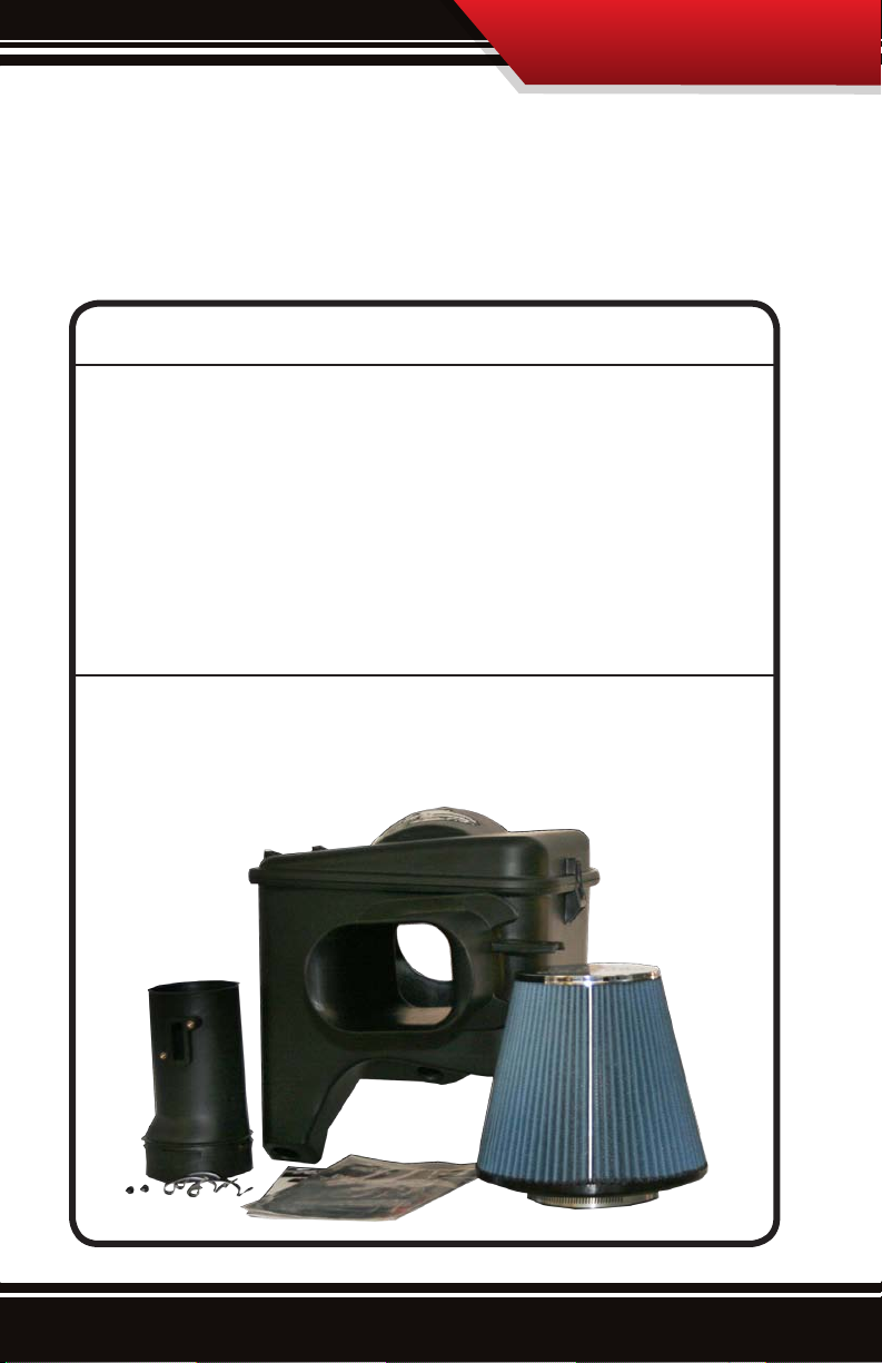
Parts Included
Parts Included and Tools Needed:
This section displays the parts included in the package and the tools needed to properly
install the system.
Parts Included
RFI Base
RFI Lid
(3) Pre-Attached Lid Latches
Air Filter Tube with MAF mount
(2) Stainless black oxide MAF screws
Air Filter
Air filter Band clamp
Product Information Packet
TOOLS NEEDED
Flat head screw driver
Phillips screw driver
Bit driver
2
Page 4
Parts Description
Parts Description:
This section describes each part and any special features of each part that need to be noted
to assist with installation. All parts will be referred to during installation by the names used
in this section.
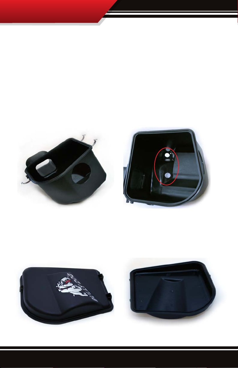
The RFI base: The base to the enclosure that holds the lter has a couple of features to
note. The rst is the circular hole on the back of the base, this hole is where the RFI tube
will snap into the base and hold secure the air lter. The second important part of the base
are the two circular holes, the rubber grommets from the stock intake will be placed there
during installation.
The RFI Lid: The lid is very easy to remove for lter maintenance, be aware that the tongue
and grove formed between the housing base and the lid needs to be properly lined up for a
good seal. The latch mounts on the lid should always match up with the latch mounts on the
base.
3
Page 5
Parts Description
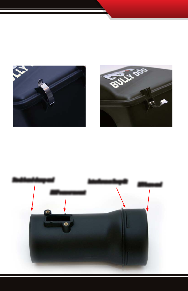
Lid Latches: The lid latches come pre-assembled onto the RFI base and are used to secure
the lid to the base. This latch system is typical of many OEM style systems and allows for
quick and easy access to the air lter for maintenance and to clean out any debris which
may have collected inside of the lter housing.
Air Intake Tube with MAF mount: The injection molded tube comes with a precisely
manufactured Mass Air Flow sensor mount with inset screw mounts. The tube also has a
unique interference snap t feature that will tightly secure the intake tube to the RFI base.
Notice in the diagram below which end of this tube goes into the RFI base.
Stock band clamp end
MAF sensor mount
Interference Snap t
RFI base end
4
Page 6
Parts Description
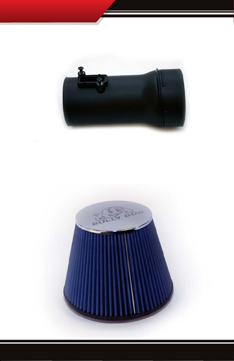
Stainless black oxide screws: The two Phillips style stainless black oxide screws included
with the kit are used to secure the MAF sensor to the air intake tube.
Air lter and clamp: The air lter included is an ISO 5011 certied eight layer oil lter. The
air lter is secured onto the end of the air intake tube using the lter clamp and a at head
screw driver.
5
Page 7
Stock Removal
Installation Overview:
Installation is very simple, it is separated into three parts: Removing the Stock Intake,
Preparing the RFI intake for installation, and Installing the RFI intake system. The complete
installation of the RFI intake system should total about 20 minutes.
Removing the Stock Air Intake:
Follow the steps in this section for guidance on how to remove the stock air intake.
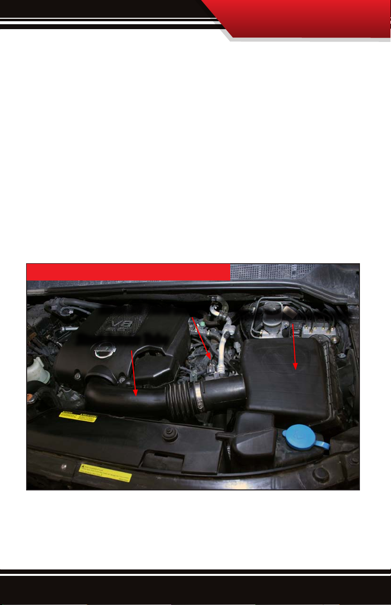
Stock intake Overview Diagram: The stock intake can be seen in the picture below.
Notice the important parts of the stock air intake that are noted in the diagram below. These
items are referred to throughout these instructions.
Stock Intake overview 5.6L Nissan
Mass Air Flow sensor
Stock Intake Tube
Stock Intake enclosure
6
Page 8
Stock Removal
Removing the stock intake continued:
1. Unplug the Mass Air Flow sensor: before going right for the sensor use a at head screw
driver to remove the harness clip from the stock intake enclosure.
Once the clip is removed unplug the mass air from harness from the mass air ow sensor.
Move the harness to an area where it will not get damaged during installation.
7
Page 9

Stock Removal
2. Start removing the stock intake by rst removing the 10mm screw/bolt that is located
over the fender well of the vehicle; the screw/bolt can be removed with a Phillips head
screw driver or a 10mm socket and driver.
3. Use a at head screw driver to loosen the band clamp that holds the stock intake tube
onto the stock lid. Once the clamp is loose, separate the stock tube from the lid.
8
Page 10

Stock Removal
4. Disconnect the stock lid from the base, remove the lid and the stock air lter so that all
that remains is the bottom portion of the stock air lter enclosure.
5. Locate and loosen the two
10mm bolts that are visible in
the intake bottom. Once both
bolts are loose remove the stock
intake bottom by carefully pulling upward and outward on the
intake.
9
Page 11

Stock Removal
6. The bolts that hold the intake in place may come out along with the intake. Remove the
bolts from the rubber grommet and reinstall the bolts onto the fender well.
7. Once those two bolts have been replaced the removal of the stock intake is complete.
Move to the next section.
10
Page 12

RFI Prep
Preparing the RFI intake for installation:
The steps in this section will prepare the RFI intake for installation. This section includes
steps that are necessary or easier to complete with the intake outside of the vehicle.
1. Remove the rubber grommets from bottom portion of the of the stock intake and transfer
them over to the RFI.
The picture below shows the RFI with the stock grommets installed.
11
Page 13

RFI Prep
2. Remove the rubber grommet and metal insert on the stock enclosure base. Transfer the
those parts over to the RFI base. It is easier to remove the metal insert and then the rubber
part rather then attempting to remove the entire piece at one time.
When placing this part onto the RFI base, rst put the rubber part into position and then
push the metal insert up through the rubber from the bottom so that the at side of the
metal insert sits at the bottom.
12
Page 14

RFI Prep
3. Carefully remove the foam from the stock
intake. The foam has some glue holding it
in place so the foam may rip if it is pulled o
too quickly.
4. Replace the foam onto the RFI. This foam
will create a seal against the fender well to
help ensure that no hot air travels from the
engine bay to the fender well.
5. Remove the MAF sensor from the stock intake using a phillips head screw driver. Place the
MAF sensor into the RFI tube and secure it using phillips head screw driver and the stainless
black oxide screws. See the installed picture on the following page.
13
Page 15

RFI Prep
6. The nal step in preparing the RFI for installation is to insert the RFI tube into the RFI
enclosure. Insert the RFI tube into the hole on the RFI base and then press inward until the
tube snaps into place. If the tube is properly in place then all of the interference snap ts
will be on the inside of the RFI base and the tube will actually rotate fairly easily.
14
Page 16

RFI Installation
Installing the RFI intake:
With the intake now prepared for installation move to the vehicle and prepare to install.
1. Start by taking the RFI base with the intake tube attached and place it into the engine
bay. When setting it into place, as the picture illustrates below, point it downward to get
the fender tube to go through the hole that leads into the fender well. It is a tight angle so
do not try to force the tube through the fender well. Once the tube is into the fender well
set the intake down into the intake cavity of the vehicle, note that the Stock Intake tube will
need to be moved to the side a bit.
15
Page 17

RFI Installation
2. When setting the intake in place make sure that the grommets in the bottom of the
intake are lined up with the bolts that are installed in the intake cavity. Push downward on
the intake until the head of each bolt is on top of each of the two grommets.
16
Page 18

RFI Installation
3. With the intake secure connect the stock intake tube to the RFI tube.
4. Before securing the connection between the stock tube and the RFI intake tube make sure
that the RFI intake tube lines up the way it does in this picture with the MAF sensor pointing
outward toward the wind shield. Then secure the tube by tightening the stock clamp with a
at head screw driver.
17
Page 19

RFI Installation
8. The nal step in securing the RFI base is to insert the screw/bolt that goes into the back of
the intake base situated over the fender well. This can either be screwed in using a phillips
head screw driver or using a 10mm socket.
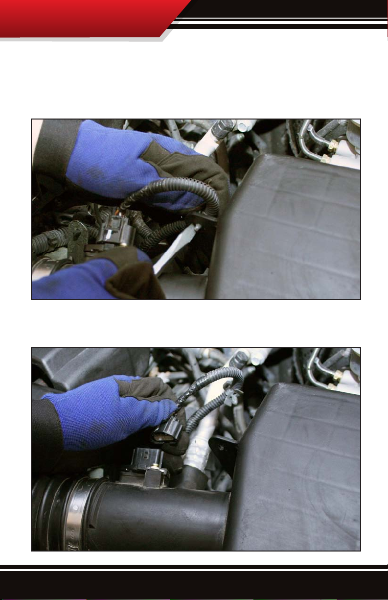
9. Once the intake base is secure the MAF sensor can be plugged in, but before plugging the
MAF sensor in the sensor harness needs to be moved. Unclip the harness from the metal
post that is situated just behind the stock intake tube as in the picture below.
18
Page 20

RFI Installation
10. Notice once the clip is undone that there is an identical clip that is closer to the end of
the harness. Insert that clip into the metal post and then plug the harness into the MAF sensor which is attached to the RFI intake tube.
9. Install the air lter onto the RFI intake tube. Secure the air lter by tightening the lter
band clamp using a at head screw driver.
19
Page 21

RFI Installation
10. The nal step in installation is to secure the lid by pulling the latches over the latch
mounts on the lid. Then go for a drive and enjoy the ride!
For Filter Maintenance and Prelter information check the next page.
20
Page 22

Filter Maintenance
Filter Maintenance:
The intake system should be cleaned at least once every three months; in dusty climates the lter
should be cleaned more often. Use a Prelter to extend time between cleaning. Cleaning the intake
is a two part process, the rst part of the process involves the physical cleaning of the lter with soap
and water and the second part involves oiling the lter. To properly clean the lter, a Bully Dog cleaning kit should be used. Cleaning kits are available at any Bully Dog
dealer.
PART 1, CLEANING THE FILTER:
1. Remove lter from lter housing. Clean the lter housing if
necessary.
2. Begin the cleaning process by ridding the lter of any dirt by
lightly tapping it. Then brush away any loose particles with a
soft-bristle brush. This step can usually be avoided with the
use of a prelter.
3. Spray cleaner generously over entire lter and let soak for
10 minutes.
4. Thoroughly rinse the lter with regular tap water (avoid
high-pressure hoses). Flush from the inside out or clean side
to the dirty side to prevent dirt from entering the lter.
5. Let the lter air dry before oiling, do not use any method to speed up the drying process. Using
a blow dryer or compressed air can cause the lter to disgure which would then allow particles
to pass through the lter.
PART 2, OILING THE FILTER:
1. Apply a small amount of oil to the soft bristle brush and spread the oil over the lter. Be sure to
apply a small amount of force so not to damage the lter element.
2. Continue applying oil to the lter using a soft bristle brush until the entire lter is covered in an
even amount of oil, just enough to give the lter a solid blue color. Apply enough oil to make the
lter a solid and uniform blue, but do not go beyond that.
3. Allow oil to sit for 20 minutes. Re-oil any dry spots that appear. Do not oil lter excessively. Excessive oiling can cause damage to intake sensors.
21
Page 23

Prelter
Bully Dog PreFilter
The time between scheduled lter maintenance can be extended. Using a Prelter will prevent all
large debris from getting into the ribs of the lter. When using the prelter only ne dust particles
make it through the prelter and onto the exterior of the lter. Thus when using a prelter,
scheduled cleaning easy much easier and lter life is even positively eected.
AIR FILTER PREFILTER
• Extend Time Between Cleanings
• Hydrophobic Material Repels Water
• Protects Cone Filter from Large Debris
• Maintains Filter Airow Between Cleanings
22
Page 24

Bully Dog Technologies, LLC is a team built on integrity that is dedicated to leading the vehicle performance
industry with an uncompromising code of ethics demonstrated in the soundness of its employees, excellent
customer service and superior products.
UNLEASH THE POWER
WITH BULLY DOG PERFORMANCE PRODUCTS
Triple Dog GT Fuel Reformulator
Nissan Aluminized single and dual
3.5” Exhaust systems
See More at: bullydog.com
For a full listing of Diagnostic Trouble Codes go to: www.bullydog.com/DTC.php
Clothing
Doc.# 54100-99 v1
®
For Free Technical Support
Call: 866-bullydog (866-285-5936)
 Loading...