

Page 1

INSTALLATION MANUAL
Vehicle Application Part #
Ford (6.0L) ‘03-’07 40300
GM (6.6.0 L) ‘01-’07 40300
Dodge (5.9 L) ‘03-’07 40300
Page 2

1
Parts Description PMT Installation Operating Instructions Internet Updates Appendix
TROUBLESHOOTING:
If you have questions during the installation of this product,
please visit www.bullydog.com/Product_Updates.php.
The latest version of these instructions can be found at the
same location. Please review the Troubleshooting section on
page 66 before calling technical support to cover most common issues.Technical support is available by calling 866bullydog (866-285-5936).
TABLE OF CONTENTS
INTRODUCTION ..........................................................................................................PG. 3
BILL OF MATERIALS.....................................................................................................PG. 4
PARTS DESCRIPTIONS ..............................................................................................PG. 57
PMT INSTALLATION ..............................................................................................PGS. 827
Installation Overview .............................................................................................pg. 8-9
Section 1: Mounting the Cradle........................................................................... pg. 10-18
Custom A-Pillar mounting........................................................................................................................11-13
Dash mounting .........................................................................................................................................14-17
Windshield mounting .................................................................................................................................... 18
Section 2: Pyrometer and Pyrometer Connection Head ........................................ pg. 19-23
Installing the pyrometer ...........................................................................................................................20-22
Installing the PCH .......................................................................................................................................... 23
Section 3: OBDII Adapter Plug ............................................................................. pg. 24-25
Section 4: Power Wire .............................................................................................. pg. 26
Section 5: Proper PMT Docking into the Cradle ......................................................... pg. 27
OPERATING INSTRUCTIONS ................................................................................ PGS. 2844
Section 1: Button Navigation ................................................................................... pg. 28
Section 2: PMT Setup Wizard .............................................................................. pg. 29-31
Section 3: Exploring the Main Screen .................................................................. pg. 32-34
Main screen navigation ................................................................................................................................. 32
Main screen parts description ....................................................................................................................... 33
Large gauge display types ............................................................................................................................. 34
INTRODUCTION
Introduction
Page 3

2
Parts Description PMT Installation Operating Instructions Internet Updates Appendix
INTRODUCTION
Introduction
OPERATING INSTRUCTIONS (continued) ................................................................ PGS. 2844
Section 4: Exploring the Menu System................................................................ pg. 35-58
Main menu description/navigation .............................................................................................................. 35
Change vehicle ............................................................................................................................................... 36
Install download .......................................................................................................................................37-41
Gauge setup ................................................................................................................................................... 44
Vehicle parameters ...................................................................................................................................43-44
User Options .....................................................................................................pgs. 45-50
Adjust backlight ............................................................................................................................................. 46
Adjust background color ................................................................................................................................ 47
Adjust volume ................................................................................................................................................ 48
Adjust time/date ............................................................................................................................................ 49
Reset to default .............................................................................................................................................. 50
Defueling Parameters .......................................................................................pgs. 51-52
Set defuel levels ............................................................................................................................................. 52
Transmission Tune (6.0L Only) .................................................................................pgs. 53
Adjust Tire Size .......................................................................................................pgs. 54
Diagnostics ............................................................................................................pgs. 55
Show Settings ........................................................................................................ pgs. 56
Update PMT Software........................................................................................pgs. 57-58
PMT INTERNET UPDATE INSTRUCTIONS .............................................................. PGS. 5962
Section 1: PMT Version Information ......................................................................... pg. 60
Section 2: The Update Agent ..................................................................................... pg.61
Section 3: The Update Process ...................................................................................pg.62
APPENDIX ......................................................................................................... PGS. 6367
Section 1: Pyrometer Calibration ............................................................................. pg. 63
Section 2: Transmission Relearn Procedure............................................................... pg. 64
GM Duramax 6.6L .......................................................................................................................................... 64
Ford Power Stroke 6.0L .................................................................................................................................. 64
Section 3: Custom A-Pillar Information .................................................................... pg. 65
Section 4: Troubleshooting/Error Codes .................................................................... pg. 66
Section 5: Formatting SD Card ...........................................................................pgs. 67-68
Section 6: Warranty and Disclaimer ......................................................................... pg. 67
Page 4
3
Parts Description PMT Installation Operating Instructions Internet Updates Appendix
Be sure to update the PMT through
the Update Agent before installing
on your vehicle.
INTRODUCTION
INTRODUCTION
The PMT is the most advanced vehicle downloader, controller, monitor and gauge in a single unit. This
product is engineered to provide the most benets and the greatest features of any combination of engine performance and monitoring enhancements in the automotive aftermarket. This product is easy
to install on any applicable vehicle; all operations of the PMT take place in-cab and feature on-the-y
adjustments. This owners manual comes with both installation instructions and operating instructions.
For free technical support and all product related questions call: 866-285-5936.
This instruction set outlines how to install and operate the PMT on the following:
Dodge 5.9L Cummins
‘03-’07
Ford 6.0L Power Stroke
‘03-’07
GM 6.6L Duramax
‘01-’07
Introduction
Page 5
4
Parts Description PMT Installation Operating Instructions Internet Updates Appendix
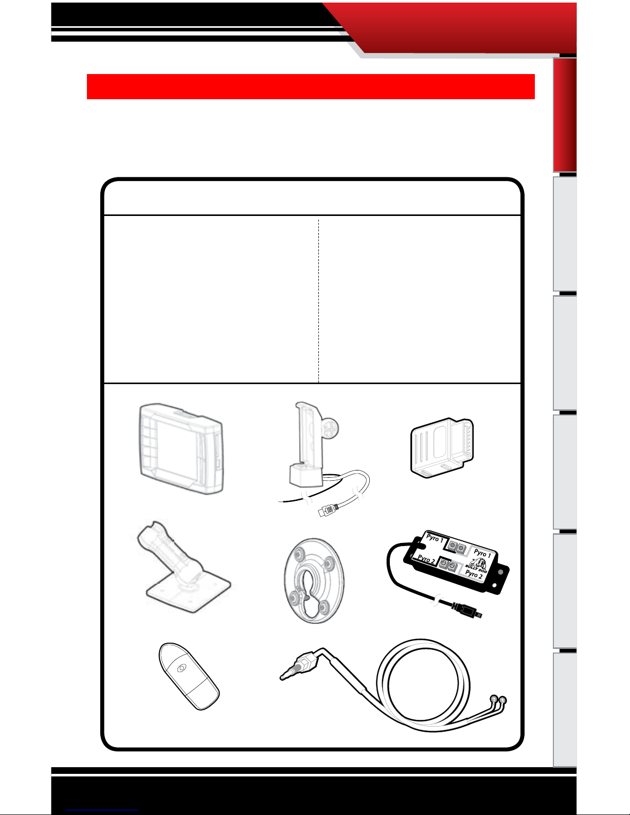
BILL OF MATERIALS
The PMT Head Unit
PMT Cradle w/ Cradle Cable & Power Wire
OBDII Adapter Plug
Dash Mount Assembly
Custom A-Pillar Mount Assembly
PCH Assembly w/PCH Cable
Pyrometer Cable
SD Card Reader
TOOLS NEEDED
• Flat Head Screwdriver
• Phillips Head Screwdriver
• Wire Strippers
• Electric Drill
• 5/16” Drill Bit
• 1/8” Pipe Tap
• 9/16” Wrench
• 5/8” Wrench
• Fuse Puller
BILL OF MATERIALS
The list below includes by name the major parts included in your PMT package. The tools list indicates all of
the tools necessary to complete the PMT install.
BILL OF MATERIALS
Introduction
Page 6
5
Introduction PMT Installation Operating Instructions Internet Updates Appendix
PARTS DESCRIPTION
Parts Description
PARTS DESCRIPTION
This section describes each of the parts in the Bill of Materials, the descriptions provide a physical set of
attributes and a purpose for each part. The parts descriptions also list everything that is included in each
assembly.
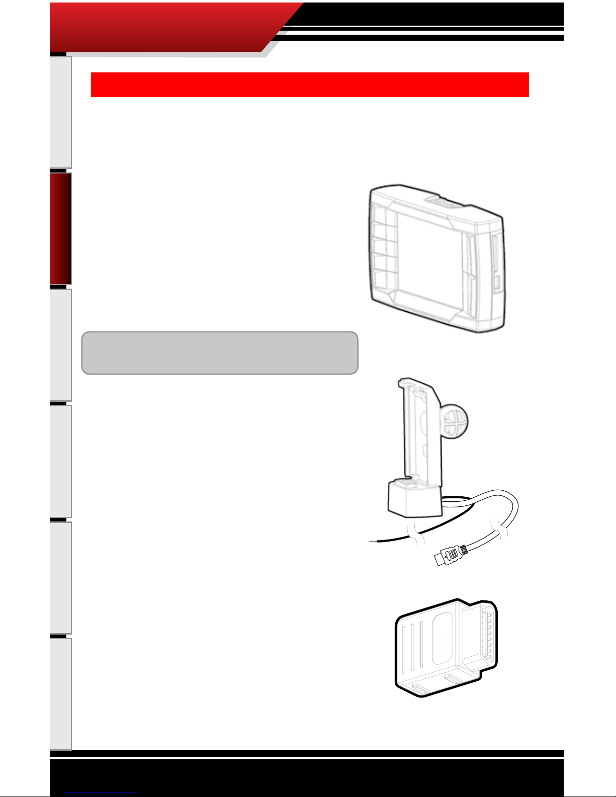
The PMT Head Unit
The main component is the PMT Head Unit. The Head Unit is
the interface in which you control vehicle performance parameters. It is also the brains that will save vehicle activity
and defuel a vehicle. Notice that the head unit has: seven total buttons, ve on the left side and two on the right, a large
color screen, an electronic plug for docking on the bottom and
a snap hinge on the top also used for docking. Note that this is
the last piece that you will install.
Note: PMT includes a SD card inserted in the side of
the
Head Unit.
PMT Cradle with Cradle Cable and Power Wire
The cradle itself is the docking station for the PMT Head
Unit. It acts as the means of communication for the PMT.
Notice that two wires come out of the bottom back side of
the cradle, the Cradle Cable and the Power Wire. During the
installation, the Cradle Cable runs to the OBDII Adapter Plug
and the Power Wire runs to the vehicle fuse box.
OBDI
I Adapter Plug
The OBDII Adapter is rectangular and has a total of four
electronic ports. The largest port on the top of the adapter
plugs into the vehicle OBDII port. The three smaller ports on
the sides include: a Cradle Cable port on one side, and on the
opposite side a 4 Pin PCH Cable port and a 5 Pin Peripheral
port. The main purpose of the OBDII Adapter Plug is to act
as a hub for all communication lines between the PMT and
the vehicle.
Page 7
6
Introduction PMT Installation Operating Instructions Internet Updates Appendix
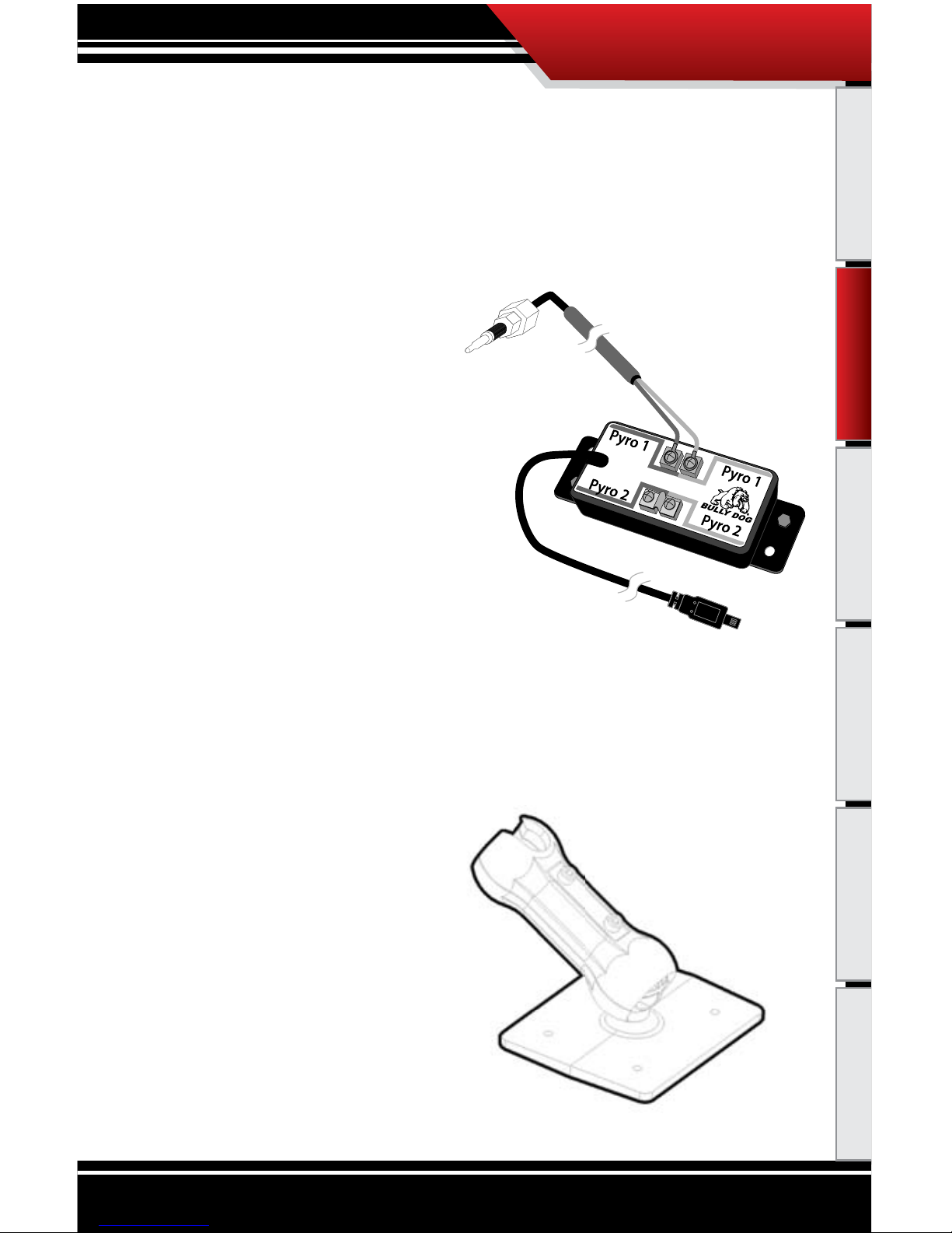
Pyrometer Connection Head (PCH) Board Assembly
The PCH Board or Pyrometer Connection Head serves as a dock to connect the pyrometers into the PMT
system. The PCH Board includes the ability to connect two pyrometers. Attached to the PCH Board housing
is a cable with four pin plug which connects to the OBDII Adapter Plug. The list below includes all separate
parts that make up the entire PCH Board Assembly.
• PCH Board
• Velcro
• (2) Self-tapping Sheet Metal Screws
• Pyrometer Cable
Dash
/Windshield Mounting Assembly
This mounting assembly is recommended mainly for use on the dash of the vehicle, but can also be used in
the same manner on the windshield of the vehicle. The assembly includes all parts and pieces necessary to
mount the cradle, along with the PMT to the vehicle dash or windshield. The list below includes all parts and
pieces of this assembly (must be assembled by installer):
• Mounting Base
• Top Cradle Arm
• Bottom Cradle Arm
• Top Aluminum Plate
• Bottom Steel Plate (threaded)
• (2) Flat-head Screws
• Double Stick Foam Tape.
PARTS DESCRIPTION
Parts Description
Page 8
7
Introduction PMT Installation Operating Instructions Internet Updates Appendix
Custom A-Pillar Mount Assembly
This mounting assembly enables the PMT to be mounted on the Custom A-Pillar Pod on the driver’s side of
the vehicle. Using this mounting style does require that a Custom A-Pillar Pod be purchased from Bully Dog,
but it also oers the cleanest install.
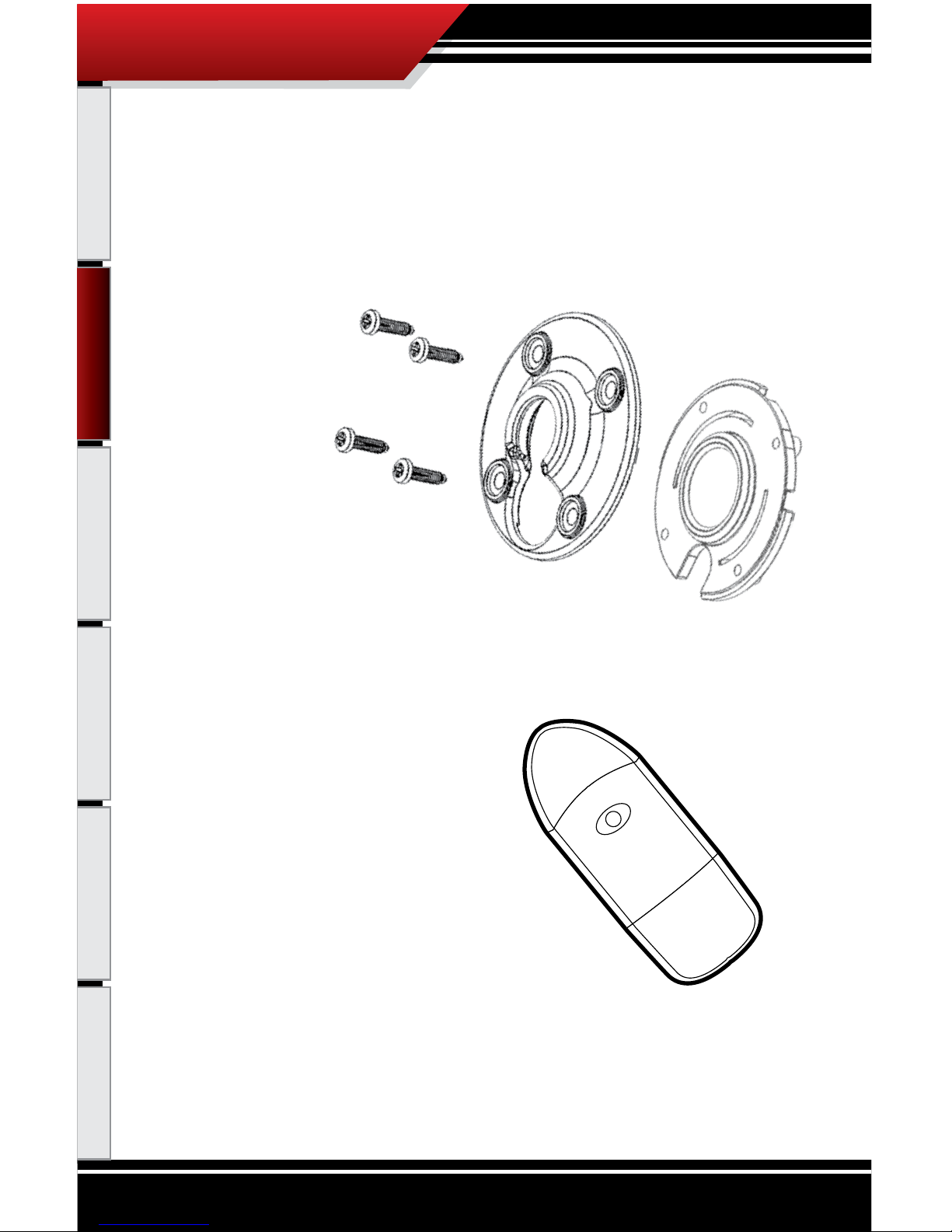
The Custom A-Pillar Mount Assembly includes:
• Front Mounting Plate
• Back Mounting Plate
• (4) Mounting Screws
USB
to
SD Card Adapter
This Card Reader is used to update the PMT’s SD memory card . It is used primarily for internet updates.
PARTS DESCRIPTION
Parts Description
Page 9
8
Introduction Parts Description Operating Instructions Internet Updates Appendix
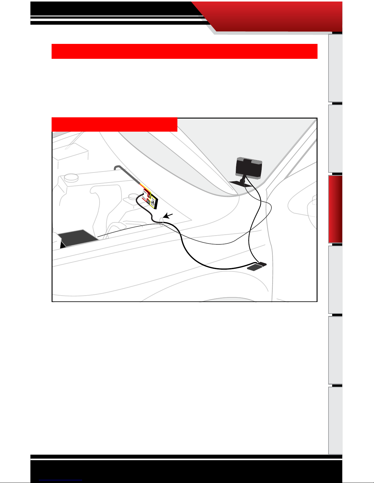
Installation Overview
PMT & Cradle
OBDII Adapter Plug
OBDII Port
Pyrometer Connection Head
Pyrometer Probe
Cradle Cable
Power Wire
PCH Cable
Fuse Box
Fire wall grommet
(to exhaust manifold)
DODGE CUMMINS ‘03’07
INSTALLATION OVERVIEW
The installation overview illustrates a totally installed and functional PMT system. This overview is meant
to help reference the general location of installed parts and pieces of the PMT. Notice that there are three
dierent overview diagrams. Each diagram is vehicle specic; one for Dodge, Ford and GM. The rest of the
installation instructions will instruct how to install the PMT in detail.
PMT INSTALLATION
PMT Installation
Page 10
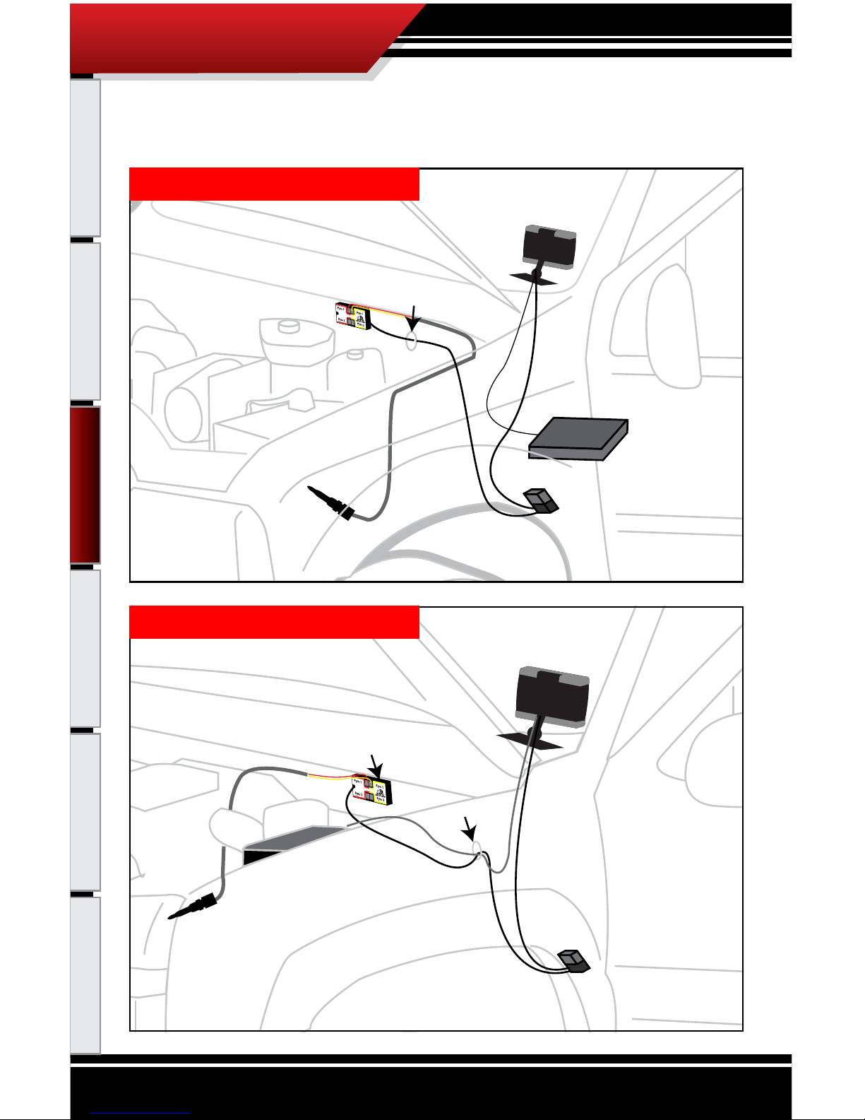
9
PMT INSTALLATION
Introduction Parts Description Operating Instructions Internet Updates Appendix
OBDII Port
OBDII Adapter Plug
Cradle Cable
Power Wire
PCH Cable
PMT & Cradle
Pyrometer Connection
Head
fuse box
Pyrometer Probe
(to exhaust manifold)
Fire wall grommet
FORD POWER STROKE ‘0307
OBDII Port
OBDII Adapter Plug
Cradle Cable
PCH Cable
(to exhaust manifold)
Fire wall grommet
fuse box
Pyrometer Probe
Pyrometer Connection
Head
PMT & Cradle
Power Wire
GM DURAMAX ‘02’07
PMT Installation
Page 11

10
PMT INSTALLATION
Introduction Parts Description Operating Instructions Internet Updates Appendix
PMT INSTALLATION INSTRUCTIONS
These installation instructions are split into ve sections. Each section provides a comprehensive description
of installation for all vehicle applications. The ve sections are:
• SECTION 1: Mounting the Cradle
•
SECTION 2: Installing the Pyrometer and the PCH Board
•
SECTION 3: Installing the OBDII Adapter
•
SECTION 4: Installing the Power Wire
•
SECTION 5: Proper docking and removal of the PMT from the Cradle
SEC
TION 1: MOUNTING THE CRADLE
In this section you will decide where to mount the PMT Cradle, so you are essentially choosing the location
for the PMT inside the vehicle cab. First, decide which mounting style you will choose for the PMT; we oer
three dierent styles of mounting:
1. Cus
tom A-Pillar mounting (most recommended)
2. Dash mounting
3. Windshield mounting
The following mounting instructions outline how to mount the PMT, explaining each mounting style
individually.
PMT Installation
Page 12
11
PMT INSTALLATION
Introduction Parts Description Operating Instructions Internet Updates Appendix
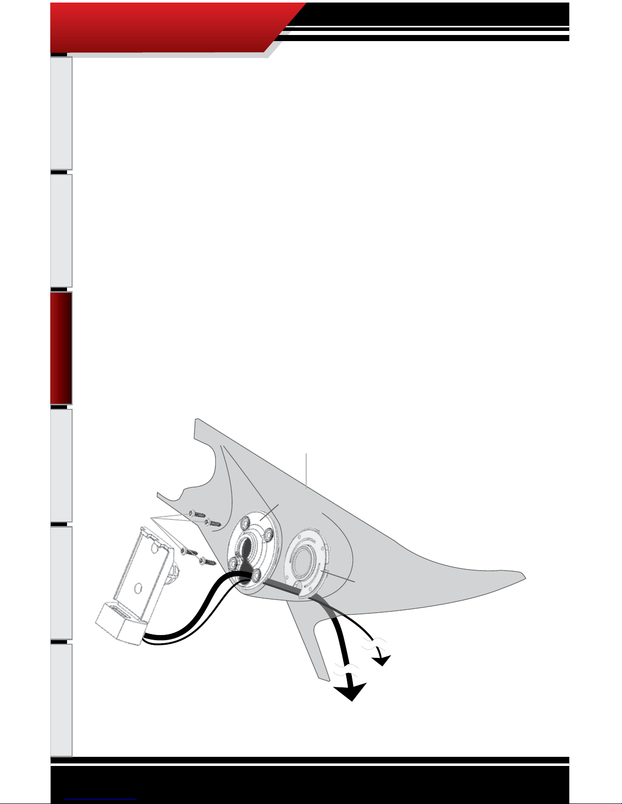
CUSTOM APILLAR MOUNTING
We recommend the Custom A-Pillar mounting style, because it makes for the best looking, most convenient and least intrusive mounting style. The Custom A-Pillar mounting style does require that a Custom
A-Pillar Pod be purchased from Bully Dog; see part numbers and vehicle applications for a Custom A-Pillar Pod in the appendix. The Custom A-Pillar mounting assembly comes in separate pieces and rst needs
to be assembled before it is installed.
TO ASSEMBLE:
1. Gather the following parts to begin assembly:
• PMT Cradle with Cradle Cable and Power Wire
• Four Mounting Screws
• Front Mounting Plate
• Back Mounting Plate
• Vehicle Specic A-Pillar Pod
PMT Cradle
Front Mounting Plate
Back Mounting Plate
(Threaded Screw Holes)
Mounting Screws
Custom A-Pillar Pod
(Not Included)
Custom A-Pillar Pod Mount Assembly Diagram
(To OBDII Adapter Plug)
(To Vehicle Fuse Box)
Cradle Cable
Ignition Fuse Wire
PMT Installation
Page 13

12
PMT INSTALLATION
Introduction Parts Description Operating Instructions Internet Updates Appendix
2. With all assembly pieces gathered, refer to the Pillar Pod Mount Assembly Diagram for a visual
reference on how the assembly ts together. Steps 3 through 6 explain how to assemble the pieces,
the A Pillar Mount Diagram shows what the assembled mounting style looks like.
Note that installation instructions for each vehicle specic Custom A-Pillar Pod are included
with the Custom A-Pillar Pod, and are not described here.
3. Insert the ball that is on the back of the cradle into the lower hole on the front of the Front Mounting Plate and then shift the ball into the center of the Front Mounting Plate. Make sure that the
extruded part of the Front Mounting Plate is facing the cradle when inserting the ball.
4. Run the Cradle Cable and Power Wire through the lower hole on the front of the Front Mounting
Plate and then through the hole on the front side of the Custom A-Pillar Pod. Pull all of the slack in
the Cradle Cable and Power Wire through the Front Mounting Plate and the Custom A-Pillar Pod.
5. With the Cradle still attached, put the Front Mounting Plate up to the hole on the Custom A-Pillar
Pod, then place the Back Mounting Plate up to the backside of the of the hole on the Custom A-Pillar
Pod. Make sure that the slot on the Back Mounting Plate is pointing downward like in the Custom
A-Pillar Pod Mount Assembly Diagram so the Cradle Cable and Power Wire can get through the
mount and down to the OBDII Adapter Plug and vehicle fuse box.
6
. Use
the four mounting screws to secure the connection of all pieces in the assembly. Tighten the
screws all the way down. See the Custom A-Pillar Pod mount diagram, nished assembly should
look identical.
7. To install the A-Pillar Pod Mount assembly on a vehicle refer to the instructions included with the
Cus
tom A-Pillar Pod.
8. Run the end of the Cradle Cable and Power Wire down through the driver’s side of the vehicle
dash and pull
all of the extra slack in the cable down also. The Cradle Cable plug will need to be
connected to the OBDII Adapter Plug and the Power Wire will need to be hooked to a fuse in the
vehicle fuse box.
PMT Installation
Page 14
13
PMT INSTALLATION
Introduction Parts Description Operating Instructions Internet Updates Appendix
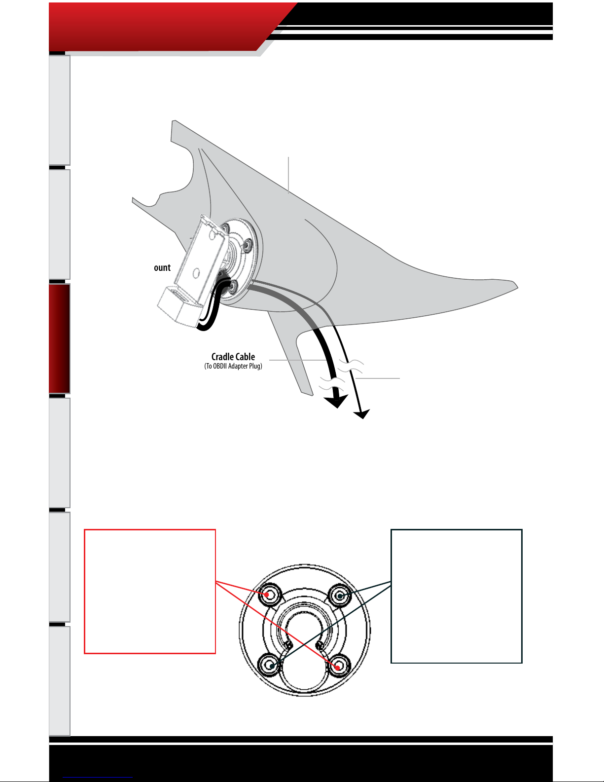
(To OBDII Adapter Plug)
(To Vehicle Fuse Box)
Cradle Cable
Custom A-Pillar Mount
with Cradle
Custom A-Pillar Pod Mount Diagram
Power Wire
Custom A-Pillar Pod
(Not Included)
TIGHTENING THE CUSTOM APILLAR MOUNT SCREWS TIP
The four screws included with the Custom A-Pillar Mount work in pairs to perform two dierent
functions in securing the cradle to the Custom A-Pillar Mount. See the diagram below for details in
tightening the screws properly.
These two screw locations
tighten the mount to the APillar itself. Only completely
tighten these screws down
when the mount is in the
A-pillar and the A-pillar is
installed on the vehicle.
These two screw locations
tighten the front and back
mounting plates together
to create a tight t over the
cradle ball. Use these two
screws to adjust the tightness of the swivel eect of
the cradle in the mount.
PMT Installation
Page 15

14
PMT INSTALLATION
Introduction Parts Description Operating Instructions Internet Updates Appendix
DASH MOUNTING
Dash mounting is a quick and easy way to mount the PMT. The dash mounting pieces do require some assembly. Dash mounting requires all parts in the dash mount assembly diagram (pg. 15).
TO ASSEMBLE:
1. Gather the Dash Mounting assembly pieces:
• Top Mounting Arm
• Bottom Mounting Arm
• The Cradle with Cradle Cable
• Dash Mounting Base with Foam Tape
• Top Plate
• Bottom plate (with threads)
• (2) Flat-Head Screws
2. Insert the metal top plate into the recessed area on top of the top mounting arm and hold it in place
while inserting the bottom plate into the bottom mounting arm (note: the bottom plate has threaded
screw holes).
3. Bring the arms together with the ends of the arms covering the ball on the cradle back and the ball on
the mounting base. When together they will form two ball joints connected by a single arm.
4. Insert the two Flat-Head screws in the two holes in the top plate and then thread them into the bottom
plate through both arm pieces. Hand tighten the screws just enough so that the assembly stays in one
piece. You will fully tighten the screws once a mounting location on the dash has been located and a
desired angle for mounting is chosen.
PMT Installation
Page 16
15
PMT INSTALLATION
Introduction Parts Description Operating Instructions Internet Updates Appendix
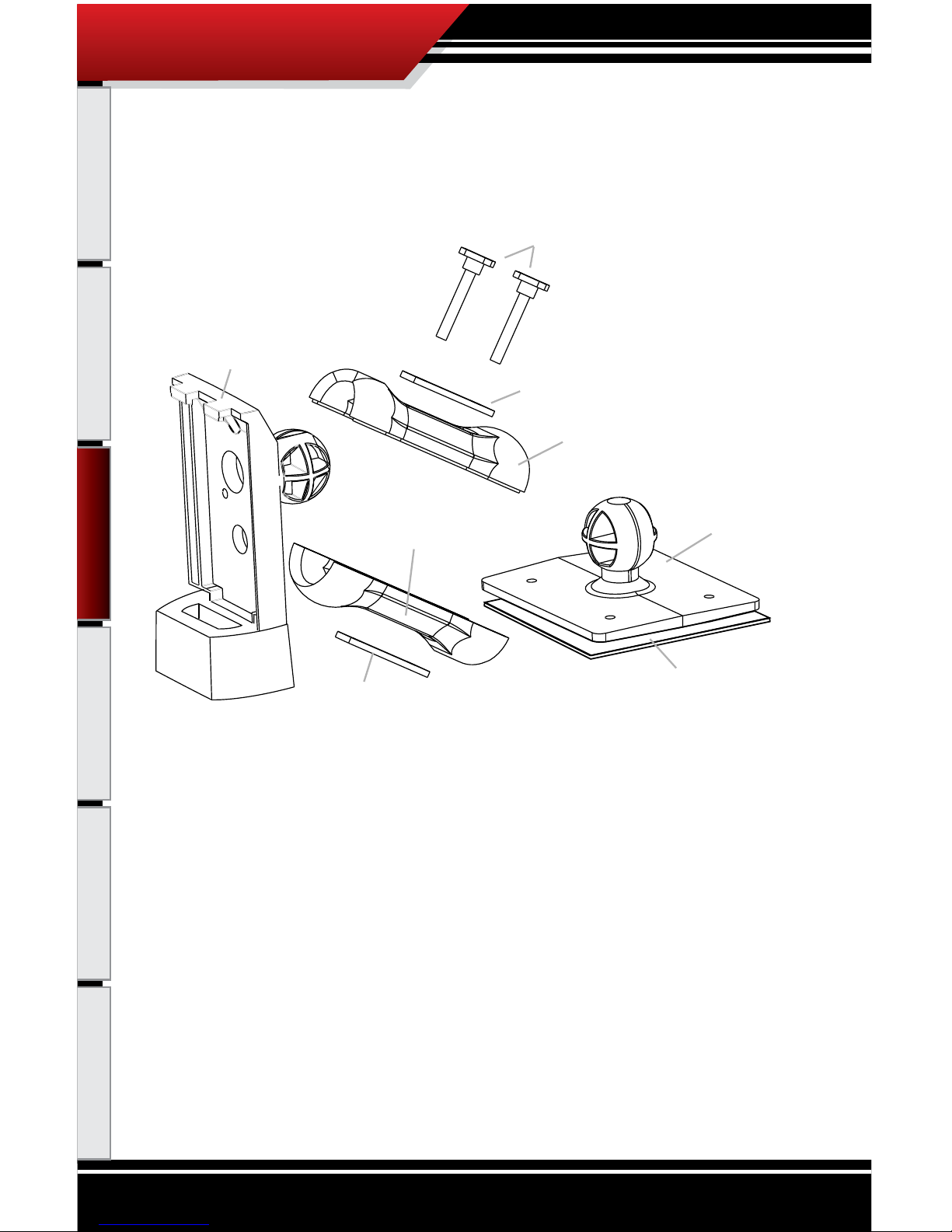
Flat Head Screws
Top Plate
Top Mounting Arm
Mounting Base
Double Stick Foam Tape
Cradle
Bottom Mounting Arm
Bottom Plate
(Threaded Screw Holes)
Dash Mount Assembly Diagram
PMT Installation
Page 17
16
PMT INSTALLATION
Introduction Parts Description Operating Instructions Internet Updates Appendix
TO MOUNT THE DASH ASSEMBLY:
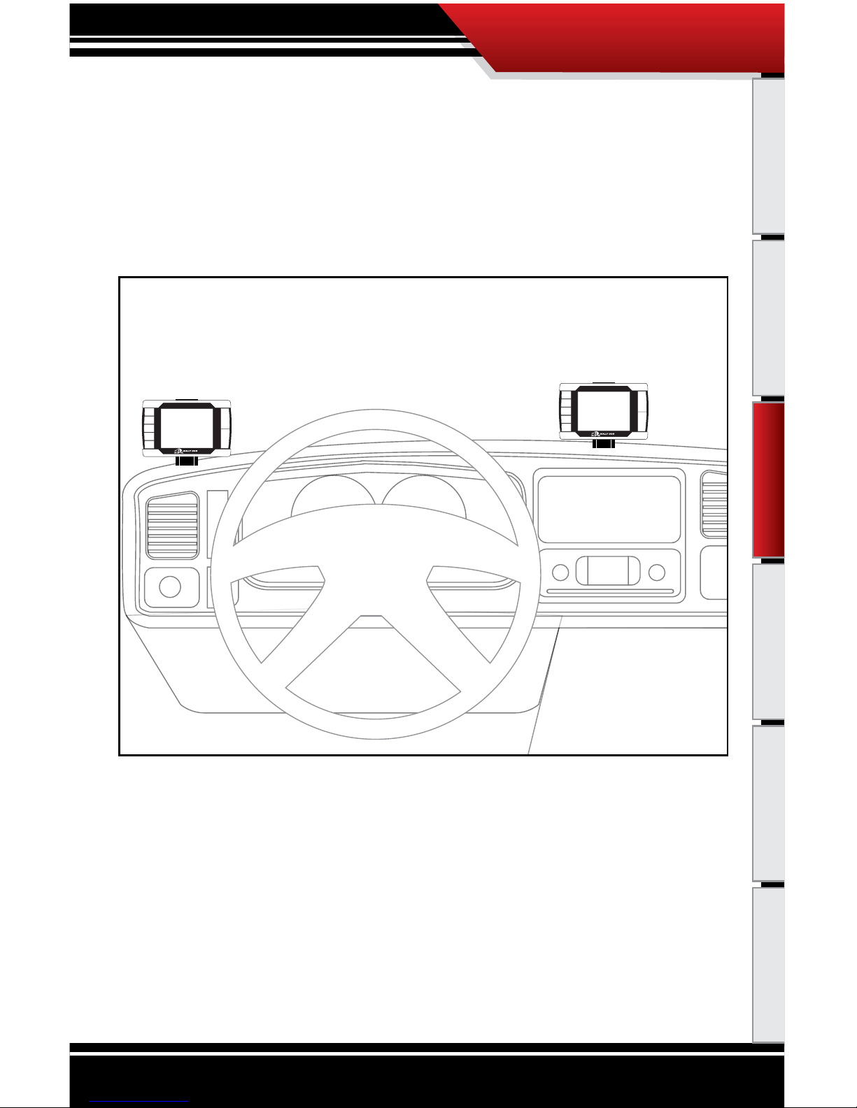
1. Use the PMT to gauge where on the dash of the vehicle you want the PMT to sit. See the dash mounting
diagram for a quick example of the two recommended dash mounting locations.
PMT Dash Mount Recommended Locations
PMT and Cradle
PMT and Cradle
PMT Installation
Page 18
17
PMT INSTALLATION
Introduction Parts Description Operating Instructions Internet Updates Appendix
TO MOUNT THE DASH ASSEMBLY: CONTINUED
2. Once a mounting location is chosen, determine the position of the PMT and direction the PMT will
face by moving the ball and socket joints of the dash mount assembly. Once you nd the right position
tighten down the two Flat-Head screws to secure that position, the screws must be tightened sufciently to hold the PMT in position.
3. Make sure that the mounting location on the dash is cleaned, preferably with isopropyl alcohol. Peal
the backing o of the double stick foam tape on the bottom of the dash mounting base and stick the
dash mount assembly along with the cradle to the dash. Press down rmly to ensure that the adhesive
reaches full contact with the dash.
4. Run
the end of the Cradle Cable down through the driver’s side of the vehicle dash and pull all of the
extra slack in the cable down also. The Cradle Cable Plug will need to be connected to the OBDII Adapter
Plug and the Power Wire will need to be hooked to a fuse in the vehicle fuse box.
Dash Mount Diagram
Dash Mount Assembly
with Cradle
Cradle Cable
(To OBDll Adapter Plug)
(To Vehicle Fuse Box)
Power Wire
PMT Installation
Page 19

18
PMT INSTALLATION
Introduction Parts Description Operating Instructions Internet Updates Appendix
WINDSHIELD MOUNTING
Follow the same instructions for the dash mount procedure; apply the same instructions to the windshield
of the vehicle rather than the dash.
PMT Installation
Page 20
19
PMT INSTALLATION
Introduction Parts Description Operating Instructions Internet Updates Appendix
SECTION 2: INSTALLING THE PYROMETER AND THE PYROMETER CONNECTION HEAD PCH
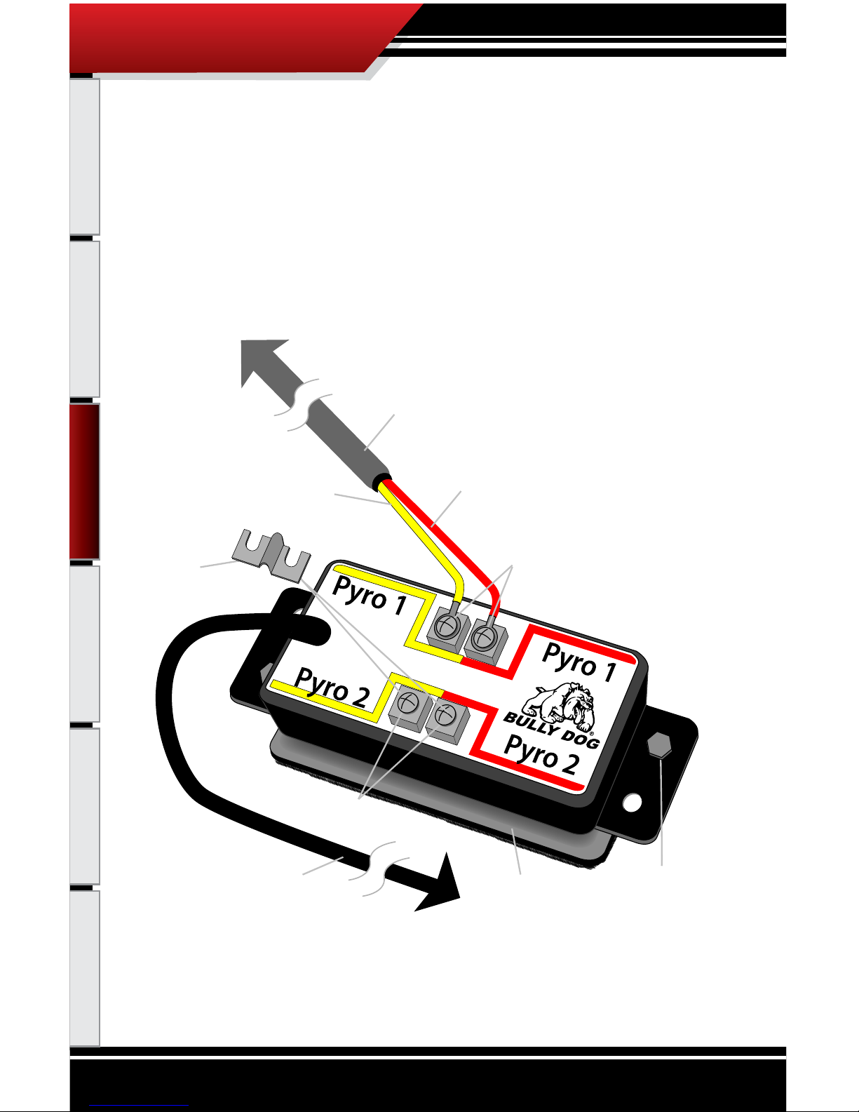
The PCH Assembly Diagram provides a quick visual description of all parts and pieces needed to acquire
pyrometer temperatures. The parts described in the diagram below will be referred to in this section of the
installation instructions.
Pyrometer Lead (Red)
(Longest of the two leads)
Pyrometer Lead Terminals (Pyro 1)
(Red on right, Yellow on left)
Pyrometer Lead Terminals (Pyro 2)
(Red on right, Yellow on left)
PCH Cable
(To OBDll Adapter Plug)
Pyrometer Lead (Yellow)
(Shortest of the two leads)
Pyrometer Cable
(To Pyrometer Probe)
Velcro Strip
(Mounting Option)
Jumper
(Connects to Pyro 2)
Sheet Metal Screw
(Mounting Option)
PCH Assembly Diagram
PMT Installation
Page 21

20
PMT INSTALLATION
Introduction Parts Description Operating Instructions Internet Updates Appendix
INSTALLING THE PYROMETER PROBE
In this section you will drill and tap the Pyrometer Probe in the exhaust, either pre-turbo or
post-turbo as a means to collect exhaust gas temperatures (EGT). Exhaust gas temperatures
indicate how hot the motor is getting and can be used to set safety defueling parameters (see
Operating Instructions Set Pyrometer defuel Level on pgs. 51-52).
POSTTURBO VS. PRETURBO
You must decide between mounting the Pyro Probe either post-turbo or pre-turbo. The dierence
in location determines what temperatures will read on your PMT. Pre-turbo mounting is generally
recommended because it provides more accurate EGT readings; the PMT is also capable of running
both pre and post-turbo pyrometers simultaneously.
It is recommended that you mount both a pre-turbo and a post-turbo Pyrometer Probe if a vehicle
is running more than 50 horsepower over stock. On screen, the PMT can display Pyro 1 and Pyro 2
which correspond to the Pyro 1 and 2 locations on the PCH board. It is very important to note if Pyro
1 is displaying pre or post-turbo exhaust gas temperatures, and the same for Pyro 2.
If installing a single Pyrometer Probe it is recommended that you install the probe pre-turbo on the
Ford Power Stroke and GM Duramax, and post-turbo on the Dodge Cummins.
Whether you mount post-turbo or pre-turbo, you need to monitor your temperatures; know what
is safe and when to back o. Use the Pyrometer Calibration Procedure in the Appendix for these
instructions to gure out what your safety limits are.
PMT Installation
Page 22
21
PMT INSTALLATION
Introduction Parts Description Operating Instructions Internet Updates Appendix
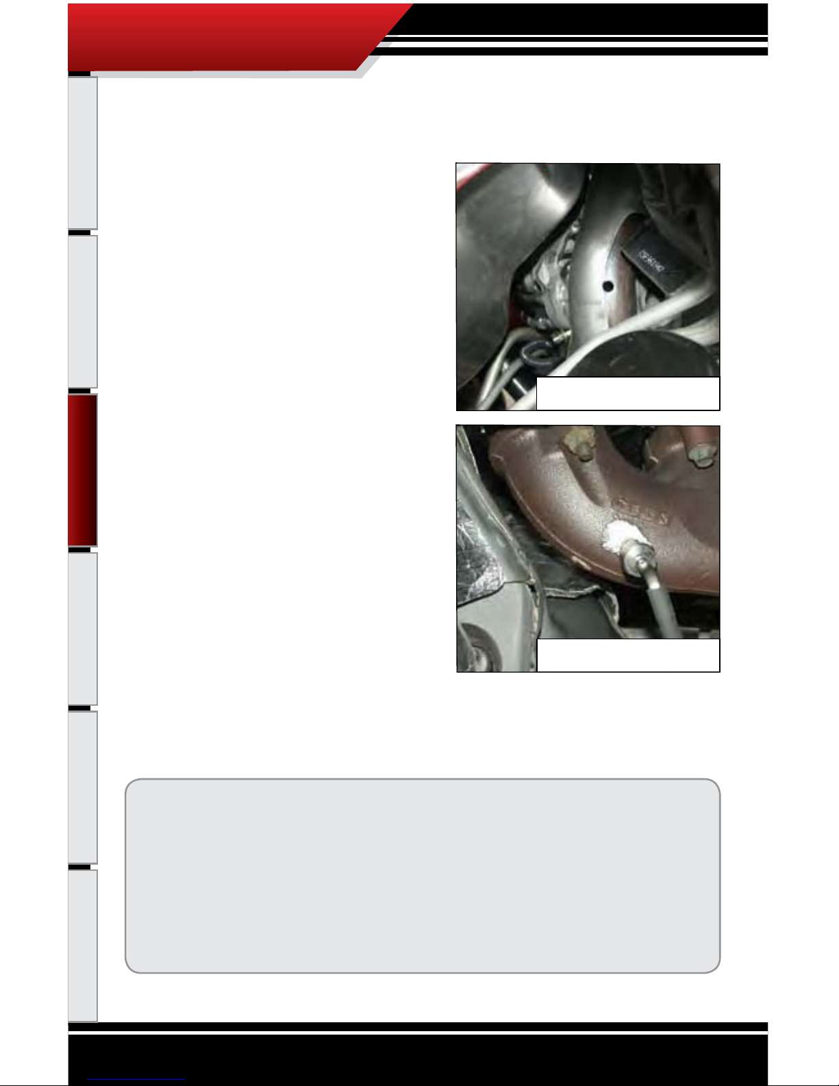
PRETURBO MOUNT:
1. Drill a 5/16” hole into the exhaust manifold where
all the exhaust runners of the manifold come together, just before the turbo exhaust inlet. Then
tap the hole with a 1/8” pipe tap and mount the
Pyrometer Probe in the hole. Use a 9/16” wrench
to tighten the probe holder or tube tting to the
down tube. Then tighten the Pyro Probe Cap to
the holder using a 5/8” wrench.
2. Run the Pyro Cable up to engine bay; let the end
of the cable sit while installing the PCH Board.
WARNING: If any debris such as drill bits and
metal
shavings drop inside the manifold, we
advise that the manifold be removed from the
vehicle so that the debris can be removed before
starting the vehicle again.
Ford Pre-turbo Mount
GM Pre-turbo Mount
TOOL TIP, PRETURBO MOUNT
When drilling into the exhaust manifold, metal spews, shavings, and broken drill bits can fall inside. This
can be hazardous to your turbo when the engine starts. Try doing four things to avoid this possible problem. One, use a high quality twist bit and a slow speed drill, about 500-800 rpm. Two, start with a small
pilot bit about 1/8”, then use the full 5/16” bit after the smaller one has punched through. Three, grease your
drill bit in addition to the normal lubricant, this will catch ying spews as they are cut. Four, just prior to
punching through into the inside of the manifold, start the engine and build up exhaust pressure on the
inside of the manifold (blows spews outside the manifold instead of letting them fall inside).
PMT Installation
Page 23
22
PMT INSTALLATION
Introduction Parts Description Operating Instructions Internet Updates Appendix
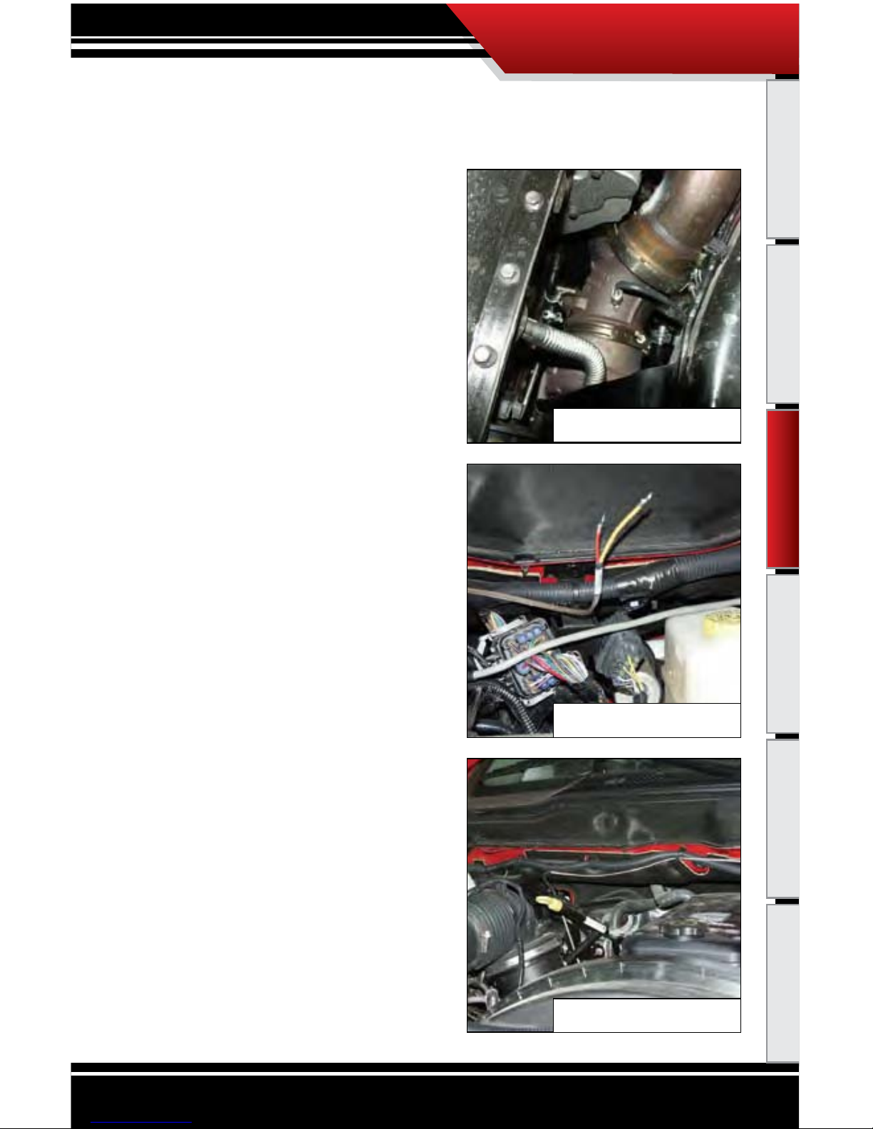
POSTTURBO MOUNT
1. Find a location on the exhaust pipe that is 3-6”
downstream from the turbo charger output. Then
drill a 5/16” hole and run a 1/8” pipe tap into the hole.
Mount the Pyrometer Probe in the threaded hole
using a 9/16” wrench to tighten the probe holder or
tube tting to the down tube. Then tighten the
Pyro Probe Cap to the holder using a 5/8” wrench.
2. Run the Pyro Cable along the brim of the engine
bay, and then let the end sit when installing the
PCH Board.
Dodge Post-turbo Mount
Securing pyro line
Pyro line secured
PMT Installation
Page 24
23
PMT INSTALLATION
Introduction Parts Description Operating Instructions Internet Updates Appendix
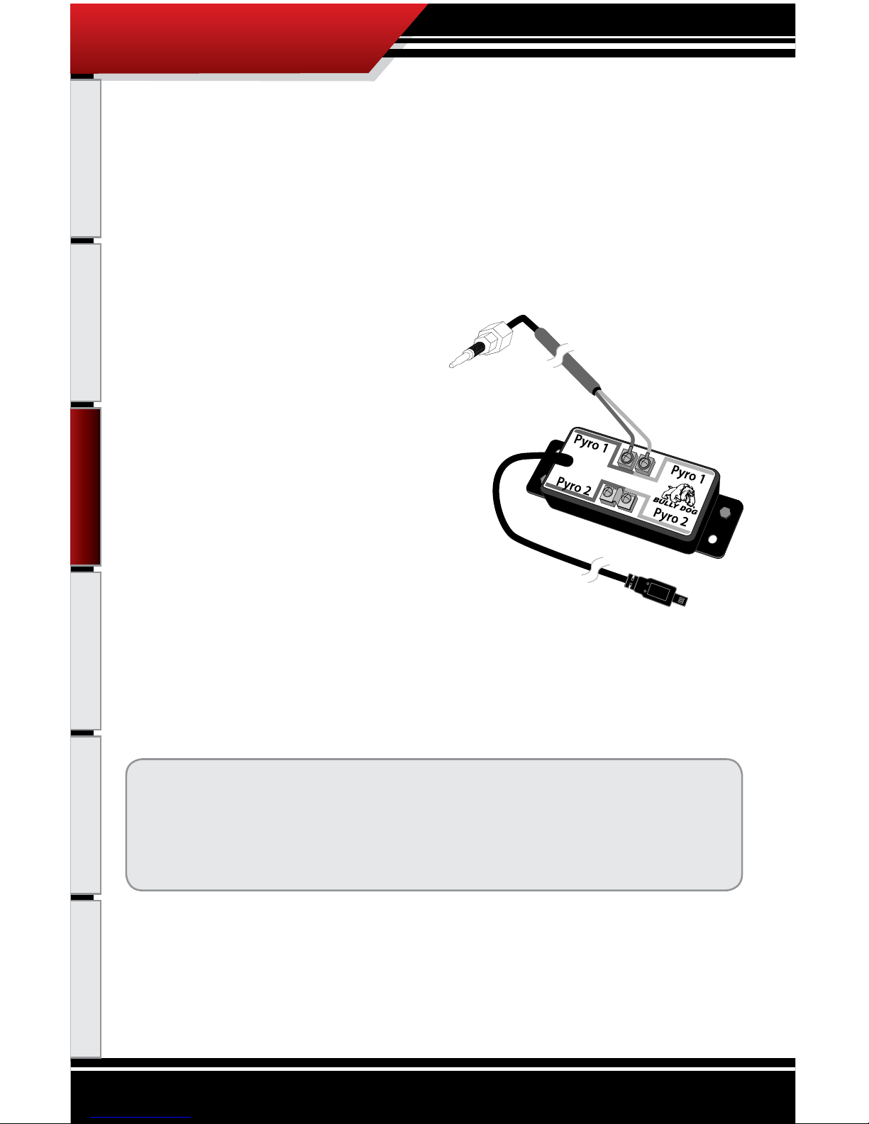
INSTALLING THE PCH BOARD
The pyrometer that was installed will now have to be connected to the PCH Board, but rst the PCH
Board needs to be mounted in a secure location that both of the pyrometer ends can reach.
1. Gather all of the parts of the PCH Board assembly:
• Pyrometer Connection Head with PCH Cable
• Self-tapping Sheet Metal Screws
• Velcro
• Jumper
• Zip Ties
2. The PCH Board needs to be mounted in a location
that is secure (away from extreme heat and moving parts), and in a location in which the end of
the Pyrometer Cable can easily reach.
3
. Use
the sheet metal screws or Velcro, or both to
securely attach the PCH Board to a safe location
within the engine bay.
4. To c
onnect the end of the Pyrometer Cable to the PCH Board, rst remove the screw and nut on
the end of the pyrometer leads, then remove the screws from the Pyro 1 heads on the PCH Board.
Use those screws to secure the Pyrometer Cable leads to the PCH Pyro 1 heads, see the PCH Assembly Diagram (pg. 19) for a visual reference when connecting the pyrometer leads to the PCH
Board.
Notice: Do not
remove the jumper from the Pyrometer 2 location unless you are
installing a second pyrometer.
If connecting t
wo pyrometers keep track of which location, Pyro 1 or 2, each
pyrometer w
as attached to on the PCH Board
5. Once the PCH Board is secure and the pyrometer(s) is/are connected to the PCH Board, use zip ties to
secure the pyrometer cables away from extreme heat and moving parts.
6. Run
the end of the PCH Cable through the re wall. It will need to be connected to the OBDII Adapter
Plug. Use zip ties to secure all remaining cable left inside the engine bay.
PMT Installation
Page 25
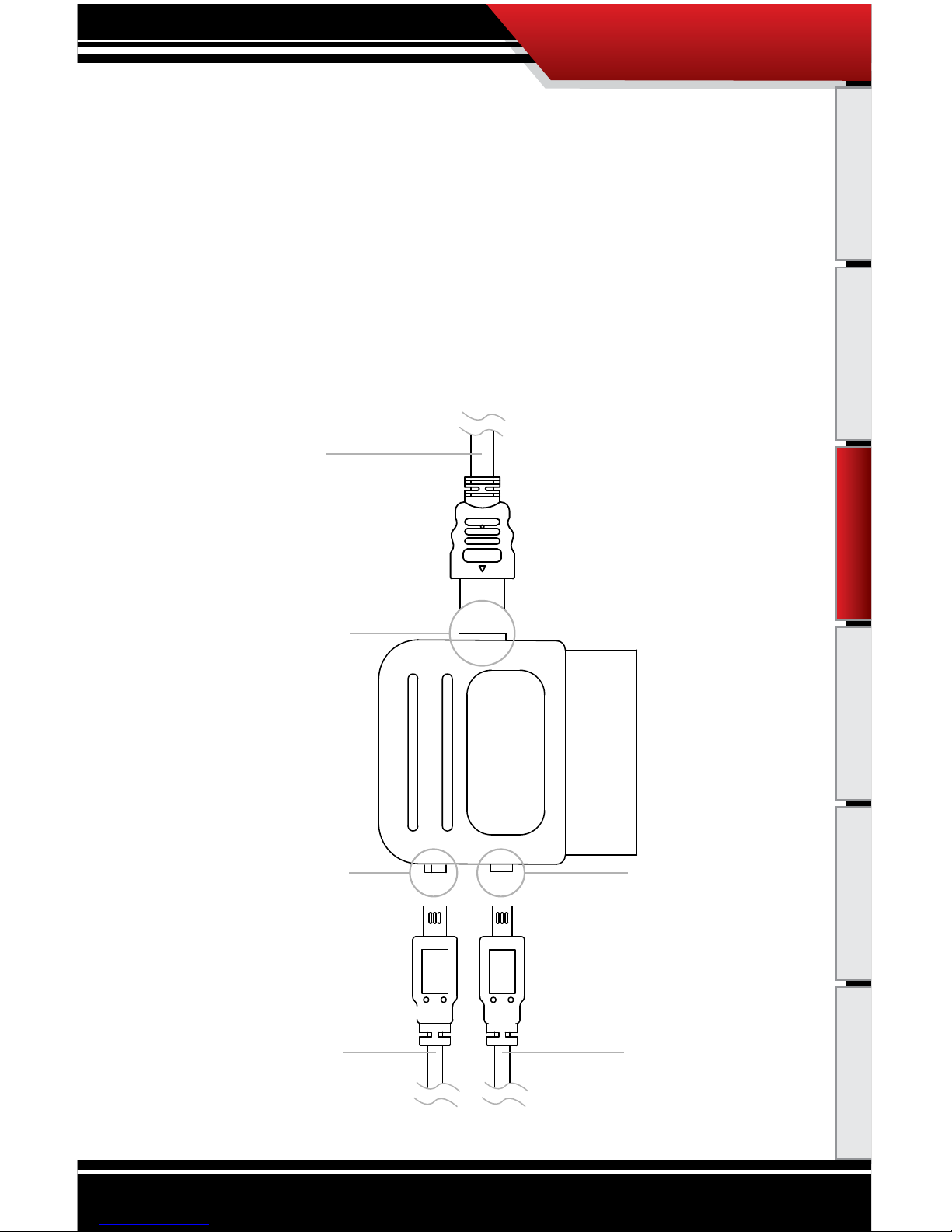
24
PMT INSTALLATION
Introduction Parts Description Operating Instructions Internet Updates Appendix
Peripheral Cable Port
Used for Bully Dog Peripherals Only
Cradle Cable Port
Used for PMT Cradle Cable
Cradle Cable
Coming from PMT Cradle
PCH Cable
Coming from Pyrometer Connection Head
* do not plug into Peripheral
Cable Port
Peripheral Cable
Used for Bully Dog Peripherals Only
PCH Port
Used for Pyrometer
Connection Head
OBDII Adapter Plug Diagram
SECTION 3: INSTALLING THE OBDII ADAPTER PLUG
In this step you will connect the Cradle Cable and the PCH Cable to the OBDII Adapter Plug and then plug
the OBDII Adapter plug into the to the Vehicle OBDII port.
1. Locate the OBDII Adapter Plug.
2
. Plu
g the Cradle Cable and the PCH Cable into the OBDII Adapter Plug. See the OBDII Adapter Plug Dia-
gram for a visual description.
PMT Installation
Page 26

25
PMT INSTALLATION
Introduction Parts Description Operating Instructions Internet Updates Appendix
SECTION 3: INSTALLING THE OBDII ADAPTER PLUG
3. Locate the OBDII port on the vehicle; OBDII ports are located under the dash on the driver’s side. These
ports are located in dierent areas under the dash for dierent vehicle applications; see the OBDII port
locations diagram.
4. Plug the OBDII Adapter Plug into the OBDII port; see the Installed OBDII Adapter Plug diagram for an
example of the nished install.
OBDII Adapter Plug
OBDII Plug
PCH Cable
Peripheral Cable Port
Cradle Cable
OBDII Adapter Plug Installation Diagram
PMT & Cradle
OBDII Port Locations Diagram
OBDII Port Locations
FordDodgeGM
PMT Installation
Page 27

26
PMT INSTALLATION
Introduction Parts Description Operating Instructions Internet Updates Appendix
SECTION 4: INSTALLING THE POWER WIRE
In this section you will run the Power Wire coming from the PMT Cradle to the vehicle fuse box and
connect it to the fuse locations specied below. The fuse location for the Power Wire is dierent on
each vehicle application.
CONNECTING THE POWER WIRE:
1. Locate the fuse box: Ford fuse boxes are located under the dash inside the cab of the vehicle; Dodge
and GM fuse boxes are located on the driver’s side of the vehicle inside the engine bay. Please see your
owner’s manual for more details on fuse box locations. Once inside the fuse box, locate the appropriate
fuse depicted in the vehicle-specic pictures below.
2. Remove the fuse, indicated in the pictures, and insert the fuse jack. Make sure that the fuse jack
is placed on the dead side of the fuse to ensure that the PMT is protected by the fuse. Use a volt
meter to verify the dead side of the fuse. With the fuse pulled and the truck powered on but not
started, the volt meter should read 0 volts on the fuse jack to ground. Problems that can occur
if the incorrect fuse is used for this connection: the power may stay on continuously even with
the key o; or, the PMT can receive power at the incorrect time of the power-on/starting cycle
of the vehicle.
3. If installing on a Dodge or a GM, run the power wire through the re wall before preparing the
Power Wire. Prepare the Power Wire by stripping the end of the wire about ¼”. Connect the blue
90° connector to the end of the Power Wire using crimping pliers.
4. Connect the Power Wire to the fuse jack, place the fuse back into the slot, and close the fuse box.
‘03-’07 Dodge: Fuse #28
‘03-’05 Ford: Fuse #33
‘01-’07 GM: Fuse “ING E”
‘06-’07 Ford: Fuse #26
Power Wire w/90º Connector
PMT Installation
Page 28

27
PMT INSTALLATION
Introduction Parts Description Operating Instructions Internet Updates Appendix
SECTION 5: HOW TO DOCK THE PMT (make sure that the vehicle key is o)
The PMT and cradle can be damaged if the PMT is not carefully placed onto the cradle. See the
diagrams below for proper installation. Note that the diagrams show the PMT being docked on to
the dash/windshield mounting styles, but the PMT docking instructions are the same for the A-Pillar
mount as well.
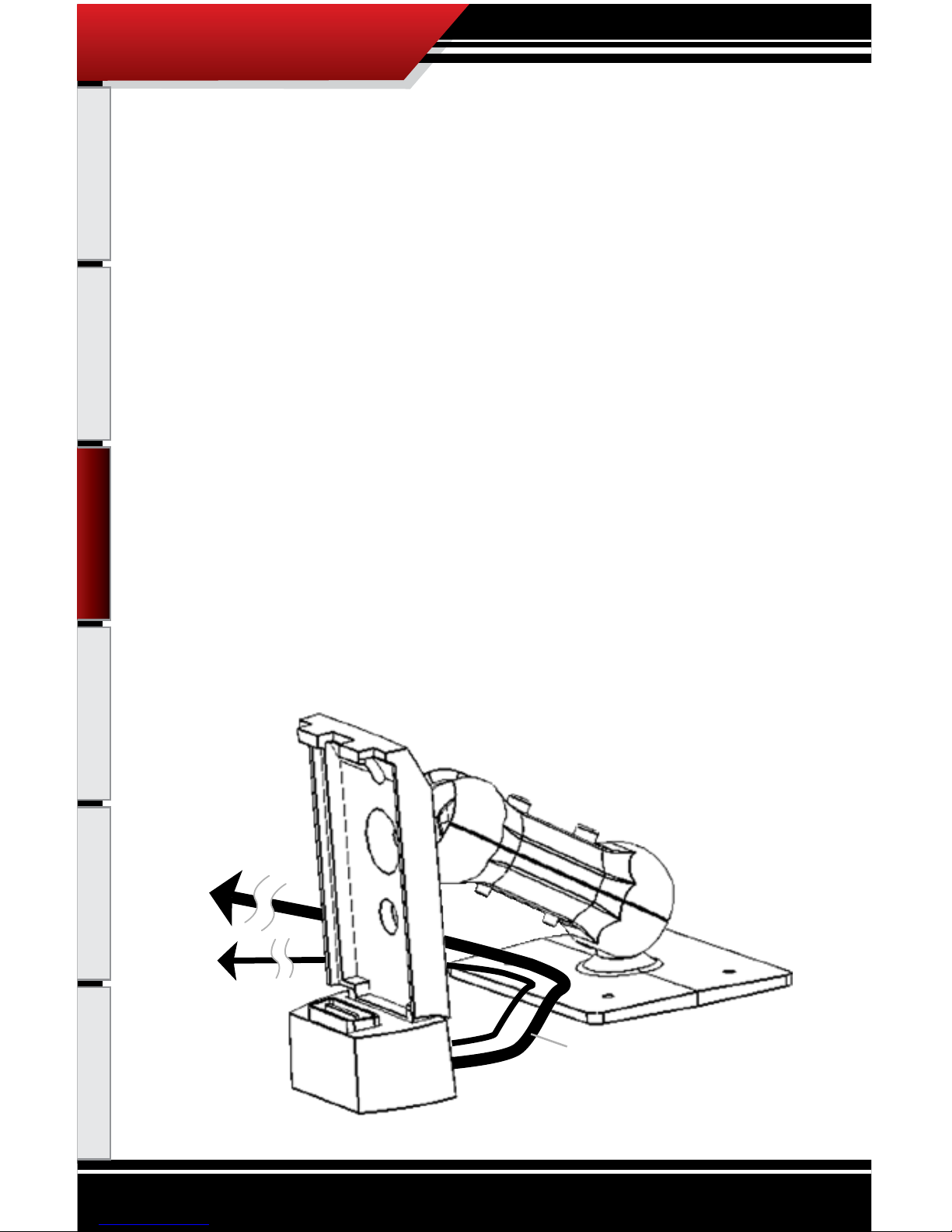
1. Make sure that the docking port on the bottom
part of the cradle is ipped forward as far as it
will go.
2. Doc
k the PMT onto the cradle.
3. Once docked, rotate the PMT back and snap it
into the cradle.
Removing the PMT:
1. When removing the PMT, simply press down on the top part of the PMT that snaps into the top of
the cradle.
2. Rot
ate the PMT forward on the docking port.
3. Pull the PMT up and out of the cradle.
Note: Check the cradle swivel to make sure that
it is connecting up to the PMT correctly. The bottom of the swivel should be ush with the bottom
of the PMT.
PMT Installation
Page 29

28
Introduction Parts Description PMT Installation Internet Updates Appendix
PMT OPERATING INSTRUCTIONS
These operating instructions are split into four sections:
• SECTION 1: Button Navigation
•
SECTION 2: Set up Wizard
•
SECTION 3: Exploring the General Display
•
SECTION 4: Main Menu and Sub Menus
SEC
TION 1: BUTTON NA
VIGATION
Speed
MPH
RPM
RPM
Coolant
ºF
Throttle
X
Menu
Power Level:
EXTREME
12:00:00 AM
Press the top left button to enter the Main Menu, also use this button to exit menus.
Press any of the four buttons on the left to
select items on the screen that coincide with
the button position.
In general these buttons work as up and
down buttons, they may also be used to
select items on the screen which coincide
with the buttons.
OPERATING INSTRUCTIONS
Operating Instructions
Page 30

29
Introduction Parts Description PMT Installation Internet Updates Appendix
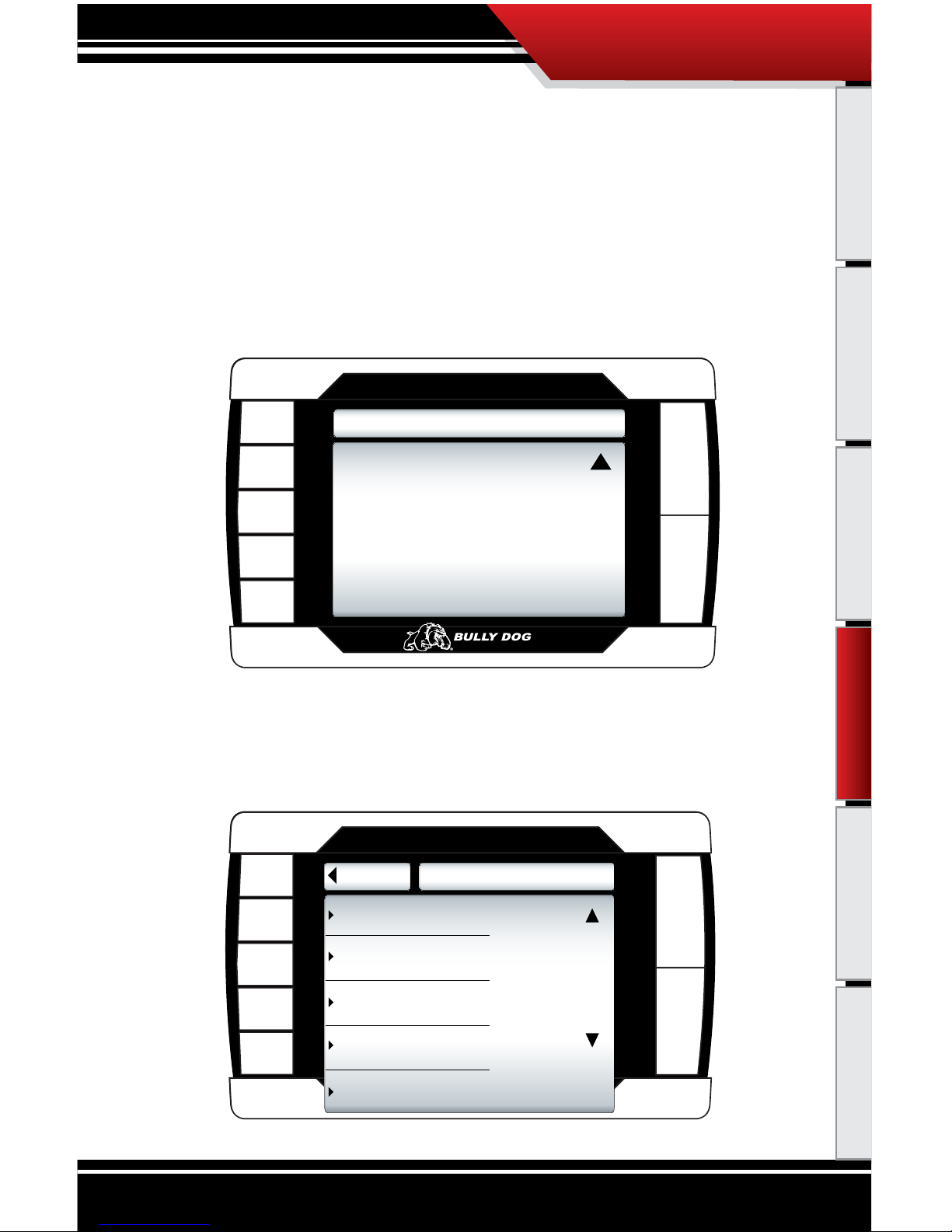
SECTION 2: SETUP WIZARD
The Setup Wizard will take you step by step through the vehicle selection process and download process. To start the setup wizard follow these three steps:
1. Pro
perly dock the PMT onto the cradle as explained in Section 5 of the installation instructions.
2. Insert the key into the vehicle ignition and turn it to the run position. Do not turn the engine on
at this point.
3. The
PMT screen will now light up and the Setup Wizard will appear on the screen.
NOTICE: If this PMT has been previously installed on another vehicle the PMT will not go through the
setup wizard, it will go strait to the Main Screen. To download under this situation you will need to navigate through the Main Menu to the Change Vehicle menu, select the correct vehicle, and then go into
the Install Download screen to initiate a download.
It is important that the information displayed throughout the setup wizard is read carefully before proceeding to the download process.
WELCOME
We l c o m e to the PMT Wizard.
Th e nex t f e w steps wi l l t ake you
through th e i n itial se t u p and
download p ro c e s s .
(
Pr ess MO RE to co nt inu e t o the ne xt sc ree n)
MO RE
OPERATING INSTRUCTIONS
Operating Instructions
Page 31
30
Introduction Parts Description PMT Installation Internet Updates Appendix
SETUP WIZARD STEP 1
VEHICLE SELECTION: What type of vehicle are you installing the Performance Management Tool on?
You will need to know the make, model, year, engine type and engine displacement. Important, if
you are not sure about the vehicle type, seek help from a certied Bully Dog products dealer or our
in house technical support sta to identify the correct vehicle. The PMT will not be able to perform a
download and will not monitor correctly if the correct vehicle type is not specied.
This diagram shows the vehicle selection screen, you should be able to identify your vehicle type
in this menu.
SETUP WIZARD STEP1
Th e followi n g m enu will a s k you
to choose w h a t vehicle t y p e the
PM T is conn e c ted to.
Be cer t a in of th e y e a r as well
as the m a k e of the veh i c l e that you
select.
(
Pr ess MO RE to co nt inu e t o the ne xt sc ree n)
MO RE
‘06-’07 Dodge 5.9L Cummins
‘01-’05 GM 6.6L Duramax
Go Back
VEHICLES
‘06-’07 GM 6.6L Duramax
‘03-’07 Ford 6.0L Power Stroke
‘03-’05 Dodge 5.9L Cummins
to Main Menu
OPERATING INSTRUCTIONS
Operating Instructions
Page 32

31
Introduction Parts Description PMT Installation Internet Updates Appendix
SETUP WIZARD STEP 2
THE DOWNLOAD: You will need to decide whether to download now or later. When installing a
download we recommend that you have access to technical assistance. Downloading the program
later is not an issue, it is very easy to load and unload the download tunes from the vehicle at your
convenience.
SETUP WIZARD STEP 2
Do you want t o d ownload?
You can e i t h er insta l l a download
now or ins t a l l later from t h e main
menu.
Your PMT will o n l y be ab l e t o run
monitorin g f e a t u res until t h e
download i s c o m pleted.
(
Pr ess MO RE to co nt inu e t o the ne xt sc ree n)
MO RE
INSTALL DOWNLOAD?
Th e downl o a d process ca n t a ke
up to twent y minutes to n ish.
We r e c o m mend th a t d o w nloading
only be d o n e when tec h i n c al
assistan ce i s avaiable.
Do you want t o i nstall n o w ?
YE S= I w a n t t o install n o w.
NO= I wi l l i nstall l a t e r.
Yes
No
Opt out: If you choose to not download at this time you will still have monitoring capabilities even though
no download has been entered into the vehicle. To download at a later time see the Install Download
instructions when ready.
Opt in: To complete the download in the setup wizard process simply press the up arrow button to
select “Yes.” Then simply follow the on screen instructions to complete a download.
OPERATING INSTRUCTIONS
Operating Instructions
Page 33

32
Introduction Parts Description PMT Installation Internet Updates Appendix
SECTION 3: EXPLORING THE MAIN SCREEN
The Main Screen is where you view all of the vehicle activity. In this section you will
learn how to navigate the Main Screen and learn about all of the dierent parts of the
Main Screen.
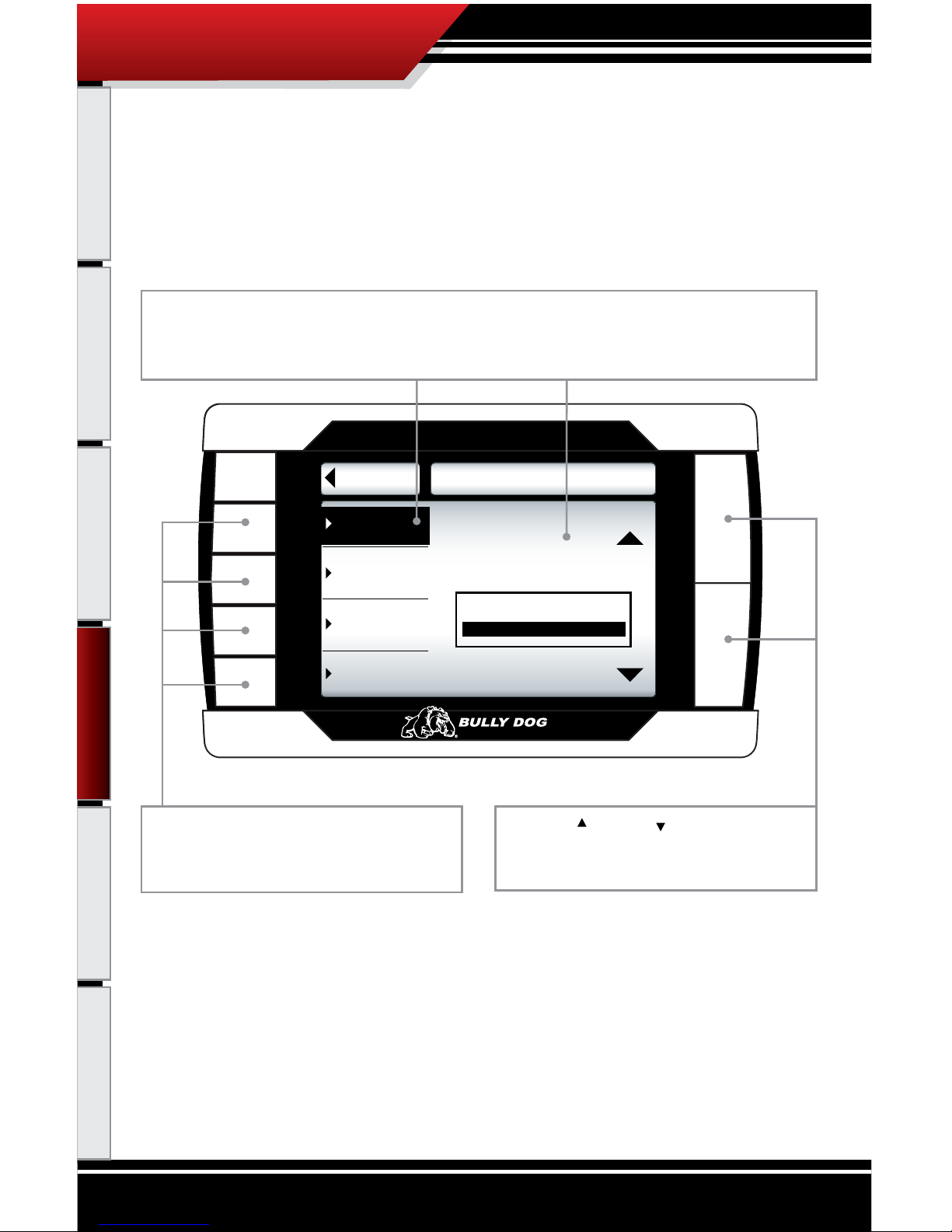
MAIN SCREEN NAVIGATION
Below are descriptions of how all of the PMT buttons work and what they do while in the Main Screen. The
buttons perform dierent functions while in a menu or submenu.
Speed
MPH
RPM
RPM
Coolant
ºF
Throttle
X
Menu
MPH
0
30
60 120
90
Power Level:
EXTREME
12:00:00 AM
Press the top left button to enter the Main Menu, also use this button to exit menus.
Press any of the four buttons on the left that
coincide with the four vehicle parameters
to display that particular vehicle parameter
on the large gauge in the upper right side of
the screen. Hold a button down to view the
dierent graph types for the large gauge. See
the dierent graph types on page 34.
Power Level Up
Power Level Down
Use the power level buttons to control power
levels on-the-y only while in the main screen
OPERATING INSTRUCTIONS
Operating Instructions
Page 34

33
Introduction Parts Description PMT Installation Internet Updates Appendix
MAIN SCREEN PARTS DESCRIPTION
This section will describe all of the dierent parts of the Main Screen.
Speed
MPH
RPM
RPM
Coolant
ºF
Throttle
X
Menu
MPH
0
30
60 120
90
Power Level:
EXTREME
12:00:00 AM
Large Gauge
Vehicle parameters: To change which vehicle
parameter is displayed in the large gauge
area simply press one of the four buttons
next the preferred vehicle parameter.
Menu button: press to enter the main menu.
Power bar: indicates power
Power level text: Displays which power level
is active, whether it be: Stock, Tow, Performance, Extreme, or Crazy Larry.
Time Clock
The black bar: The black bar highlights the title of one of the four displayed vehicle parameters to
indicate that vehicle parameter is also being displayed on the large gauge.
OPERATING INSTRUCTIONS
Operating Instructions
Page 35

34
Introduction Parts Description PMT Installation Internet Updates Appendix
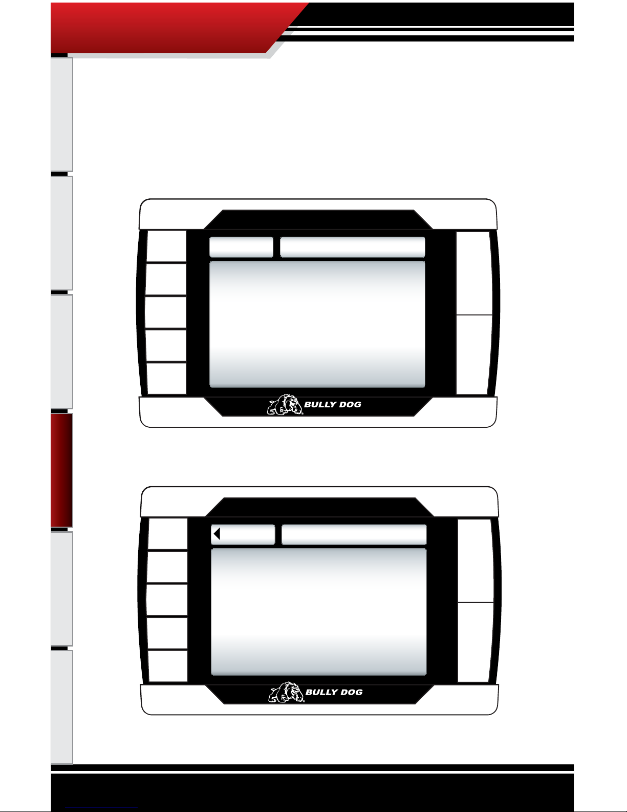
LARGE GAUGE DISPLAY TYPES
The large gauge area can be displayed in four dierent views.
Speed
MPH
RPM
RPM
Coolant
ºF
Throttle
X
Menu
Power Level:
EXTREME
12:00:00 AM
1. 2.
3. 4.
Analog gauge
with mini graph
Analog gauge
with average
and max peaks
Analog gauge
display only
Large real time
graph
Hold the button down next to the vehicle parameter currently displayed in the
large gauge area to switch between the dierent large gauge display types.
OPERATING INSTRUCTIONS
Operating Instructions
Page 36
35
Introduction Parts Description PMT Installation Internet Updates Appendix
SECTION 4: EXPLORING THE MENU SYSTEM
EXPLORING THE MAIN MENU
Section 4 will explore the entire menu system including: each main menu item and all of the sub
menus to those main menu items.
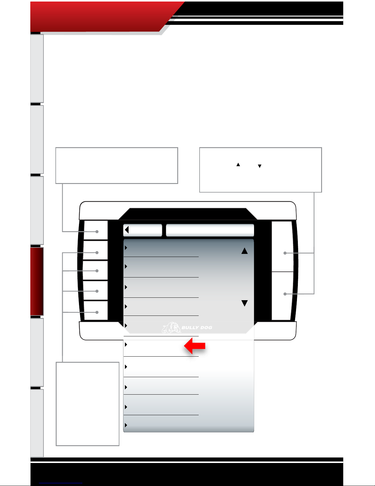
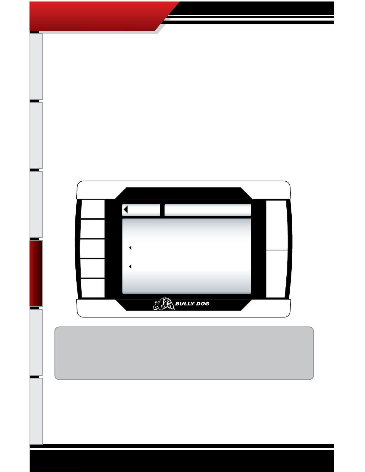
MAIN MENU DESCRIPTION/NA
VIGATION
Thediagram below shows all of the Main Menu items and explains the Main Menu navigation.
Go Back
MAIN MENU
to Main Screen
Gauge Set Up
Set User Options
Set Defuel Levels
Transmission Tune
Adjust Tire Size
Diagnostics
Show Settings
Update PMT Software
Change Vehicle
Install Download
Appears only on
Ford Power Stroke
vehicle Selection
Navigation through the main menu: Use
the large Up Down Buttons to page up
and page down through all the Main Menu
options.
These buttons are
used to enter into
the sub menus from
the main menu and
may also be used
to select additional
items when in the sub
menus.
This button is used to enter into the Main
Menu from the main screen. While in any of
the menus this button works as a back button.
Operating Instructions
OPERATING INSTRUCTIONS
Page 37
36
Introduction Parts Description PMT Installation Internet Updates Appendix
CHANGE VEHICLE:
The Vehicles Menu is only used for two reasons:
1. The PMT is being transferred to a new vehicle, in which case it is very important that you make sure that
the last vehicle was completely returned to stock before the transfer. The PMT will not work on the new
vehicle unless the last vehicle was returned to stock.
2. If
the wrong vehicle is selected when performing an install on a new vehicle during the Setup Wizard,
you will have to use the Vehicles Menu to select the correct vehicle.
When you select a new vehicle type in the Change Vehicle Menu and intend to install a download into the vehicle you will need to do so through the Install Download Submenu from the
Main Menu.
THE SD CARD MUST BE INSERTED IN THE SIDE OF THE PMT TO CHANGE VEHICLES.
‘06-’07 Dodge 5.9L Cummins
‘01-’05 GM 6.6L Duramax
Go Back
VEHICLES
‘06-’07 GM 6.6L Duramax
‘03-’07 Ford 6.0L Power Stroke
‘03-’05 Dodge 5.9L Cummins
to Main Menu
Use the large Up Down Buttons to move
between dierent vehicles.
To select a dierent vehicle, press the selection button that coincides with that vehicle
location.
Operating Instructions
OPERATING INSTRUCTIONS
Page 38
37
Introduction Parts Description PMT Installation Internet Updates Appendix
INSTALL DOWNLOAD:
The install download option comes in use for three dierent reasons:
1. Ins
tall a download onto a stock vehicle: If the vehicle is stock and you enter the install download
menu, simply follow the screen prompts to install a download on the vehicle.
2. Cha
nge Download Settings: If the vehicle already has a download on it from the PMT that is currently
installed on that vehicle. You can perform another download to change the vehicle specic options
contained in a download.
3. Ret
urn a vehicle to stock: To completely return a vehicle to its factory stock conditions you need to
select this option. This is highly recommended when taking the vehicle in for any kind of service.
This PMT screen shot shows what you will see if a download has already been entered into a vehicle.
Note before installing a download:
• Make sure that the PMT is properly docked in the cradle.
• Make sure that the harnesses have been properly installed.
• Make sure that the vehicle battery is fully charged.
THE SD CARD MUST BE INSERTED IN THE SIDE OF THE PMT TO DOWNLOAD TO A VEHICLE.
Go Back
DOWNLOAD INSTALLED
Return to Stock
Change Settings
Download Already Installed
Operating Instructions
OPERATING INSTRUCTIONS
Page 39

38
Introduction Parts Description PMT Installation Internet Updates Appendix
DOWNLOADING VEHICLE SPECIFIC FEATURES:
Each vehicle make has vehicle specic features that prompt you to opt into or opt out of during
the download process. Those vehicle specic features are described for Ford, GM and Dodge in this
section.
‘03’07 FORD 6.0L SPECIFIC FEA
TURE
SPEED LIMITER FORD 6.0L
The PMT gives racing enthusiasts the option to remove the OEM speed limiter. This allows the vehicle to reach speeds in
excess of where the OEM speed limiter was set. By selecting yes to remove the speed limiter you agree that your vehicle
has tires rated for speeds in excess of 140 mph.
SPEED LIMITER
Wo uld y o u L i ke t o Re m ove
Your Spee d Li m iter ?
YE S
NO
OPERATING INSTRUCTIONS
Operating Instructions
Page 40

39
Introduction Parts Description PMT Installation Internet Updates Appendix
‘02’07 GM 6.6L SPECIFIC FEATURES (not applicable for 2001 model years)
SPEED LIMITER GM 6.6L
The PMT gives racing enthusiasts the option to adjust the OEM speed limiter. This allows the vehicle to reach
speeds in excess of where the OEM speed limiter was set. By selecting yes to remove the speed limiter you agree
that your vehicle has tires rated for speeds in excess of 140 mph. Use the up and down arrows to set the speed
limiter to the desired mph in 5 mph increments from 50 mph to 135 mph.
SPEED LIMITER
Do yo u want t o adj u st
the S p eed L imiter ? -Y / N
DO N OT U NPLUG
YE S
NO
SPEED LIMITER
Using the U p /Down Arrows
enter the d e sired s peed
limi t e r- 9 5 M P H
Pr ess Yes to accept
Yes
Up
Do wn
OPERATING INSTRUCTIONS
Operating Instructions
Page 41

40
Introduction Parts Description PMT Installation Internet Updates Appendix
CALIBRATING THE OEM SPEEDOMETER GM 6.6L
Program in the vehicle’s exact tire size to adjust the OEM speedometer so that it will correctly display vehicle
speeds. The downloader can adjust for tires ranging from 25” to 45”.
Note that adjusting the tire size over 35” may result in an ABS light turning on in the vehicle dash.
CALIBRATE SPEEDOMETER
Using the U p/Down Ar rows
Enter Tire diameter
in inches - 33.25”
Press Yes to Accept
Yes
Ag ree
Di sagr ee
CALIBRATE SPEEDOMETER
Do yo u want t o adj u st
for T i re Si z e ? -Y /N
DO N OT U NPLUG
YE S
NO
OPERATING INSTRUCTIONS
Operating Instructions
Page 42

41
Introduction Parts Description PMT Installation Internet Updates Appendix
LOW-END POWER OPTION
Would yo u like to add
low- end power?
NOT RECOMMENDED
FO R STANDARD TRANSMISSIONS
YE S
NO
‘03’07 DODGE 5.9L SPECIFIC FEATURES (Recommended for automatic transmissions only)
LOW END POWER (Dodge 5.9L)
For improved throttle response on the bottom end of the rpm range.
LOW-END POWER OPTION
Would yo u like to add
low- end power?
NOT RECOMMENDED
FO R STANDARD TRANSMISSIONS
YE S
NO
Operating Instructions
OPERATING INSTRUCTIONS
Page 43

42
Introduction Parts Description PMT Installation Internet Updates Appendix
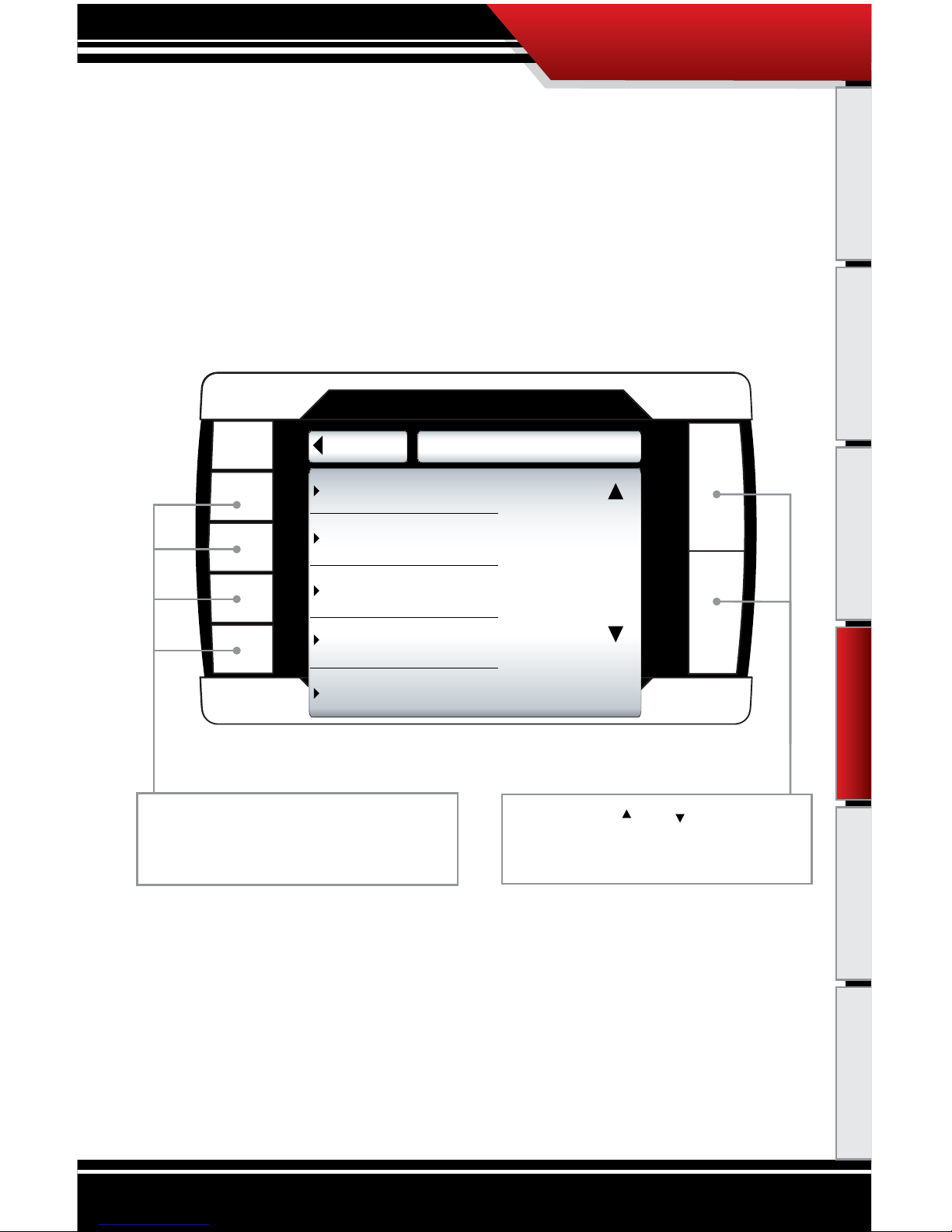
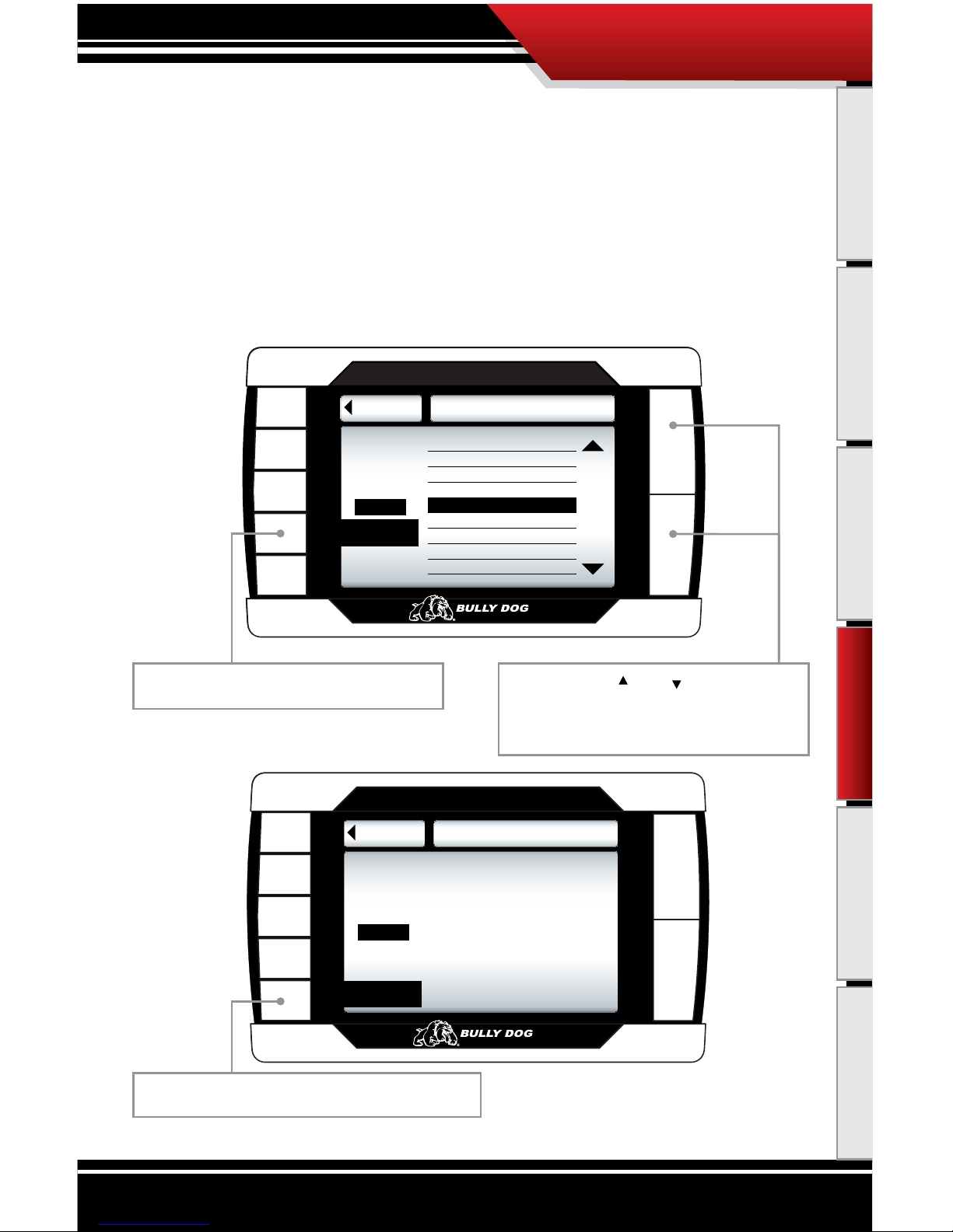
GAUGE SETUP
Enter to change the vehicle parameters displayed on the four gauge locations in the Main
Screen. This is also where you can see all of the most up-to-date vehicle parameters available
to your vehicle make and model after running an internet upgrade.
Selecting a vehicle parameter to display in a particular location is done by highlighting the gauge
location and then highlighting the desired vehicle parameter.
Once the correct vehicle parameter for a gauge
location has been highlighted, you do not need to
press another button to select that vehicle parameter. Simply highlighting the vehicle parameter
makes it active in that location.
Set Gauge 2
Set Gauge 3
Set Gauge 4
Go Back
GAUGE SETUP
Set Gauge 1
Speed
RPM
Throttle
Coolant
Gauge 1
Use the Up and Down Arrows
to Change the Gauge Function
Pyro 2
Speed
Boost
to Main Menu
To highlight a dierent gauge location press
the selection button that coincides with that
gauge location. So to select gauge location
1, press the second button down on the left
hand side of the PMT. To select the 4th gauge
location press the bottom button or the 5th
button down on the left side.
Use the large Up Down Buttons to
highlight a particular vehicle parameter for
any of the gauge locations.
Notice that upon entering the gauge setup menu that, Set Gauge 1, is highlighted in black. When a
gauge location is selected it is highlighted in black on the left and it also appears above the vehicle
parameter selection box.
Operating Instructions
OPERATING INSTRUCTIONS
Page 44

43
Introduction Parts Description PMT Installation Internet Updates Appendix
VEHICLE PARAMETERS
This diagram shows vehicle parameters which can be displayed on the PMT. Due to vehicle
specic availability the diagram also indicates which vehicle parameters are available to each
vehicle application.
FEATURES
FORD
‘03’07
GM
‘06’07
GM
‘01’05
DODGE
‘06’07
DODGE
‘03’05
Pyro 1 X X X X X
Pyro 2 X X X X X
Boost Pressure X X X X X
Speed X X X X X
RPM X X X X X
Coolant X X X X X
IPW (injection pulse width) X
Throttle Position X X X X X
Intake Temperature X X X
Barometer X
Battery Voltage X X
Oil Temperature X
ICP (injection control pressure) X X X X X
Transmission Temperature X X X
OPERATING INSTRUCTIONS
Operating Instructions
Page 45

44
Introduction Parts Description PMT Installation Internet Updates Appendix
PYRO 1:
Reads the signal received from the Pyro 1 connection on the OutLook Main harness. This measurement is used to defuel the engine based on the
Pyrometer Probe Calibration Procedure listed previously in the manual. This measurement is permanently displayed in the bottom left quadrant of the
OutLook Screen.
PYRO 2:
Reads the signal received from the Pyro 2 connection
on the OutLook Main harness. Use this feature to display EGT measurements from Pyro 2 on the screen.
SPEED:
Vehicle rate of travel in miles per hour. This feature
does not change the OEM speedometer.
BOOST PRESSURE:
A measure of air pressure generated by the turbo
that is being forced into the engine cylinder. Knowing the pressure will indicate how much stress is
being put on the turbo and the engine itself. On a
stock pickup at high acceleration, a turbo will generate 18 to 40 lbs. of boost depending upon year
and make of vehicle.
ENGINE RPM:
Number of crank revolutions per minute.
COOLANT TEMPERATURE:
Temperature of the vehicle coolant.
INJECTION PULSE WIDTH:
Amount of microseconds that the injectors are
engaged to deliver fuel to the engine.
THROTTLE POSITION:
Display real-time percentage between idle and full
throttle.
INTAKE TEMPERATURE:
Air temperature after it has passed through the air l-
ter and before it has entered the engine turbo.
BAROMETER:
Outside atmospheric pressure.
BATTERY VOLTAGE:
Current measurement of battery volts.
OIL TEMPERATURE:
Temperature of the vehicle’s motor oil.
INJECTION CONTROL PRESSURE:
Amount of pressure used to deliver fuel to the engine through the injectors.
TRANSMISSION TEMPERATURE:
Temperature of the vehicle’s transmission uid.
PMT VEHICLE PARAMETER DESCRIPTIONS
The following is a general list of vehicle parameters the PMT can display.
OPERATING INSTRUCTIONS
Operating Instructions
Page 46

45
Introduction Parts Description PMT Installation Internet Updates Appendix
USER OPTIONS
In this sub menu you get to personalize your PMT. The descriptions for all the user options are
below. A more detailed description of each is on the following pages.
• ADJUST BACKLIGHT: Change screen backligh
ting and button backlighting.
• SET BACKGROUND CO
LOR: Choose between sixteen dierent colors for the menu.
• ADJUST VOLUME: Set button f
eedback volume.
• SET CLOCK/DATE: C
hange time and date that is displayed in the general view.
• RESET TO DEFAU
LT SETTING: Revert back to Bully Dog factory settings.
Go Back
USER OPTS
to Main Menu
Adjust Volume
Set Clock/Date
Reset to Default Settings
Adjust Backlight
Set Background Color
OPERATING INSTRUCTIONS
Operating Instructions
Page 47

46
Introduction Parts Description PMT Installation Internet Updates Appendix
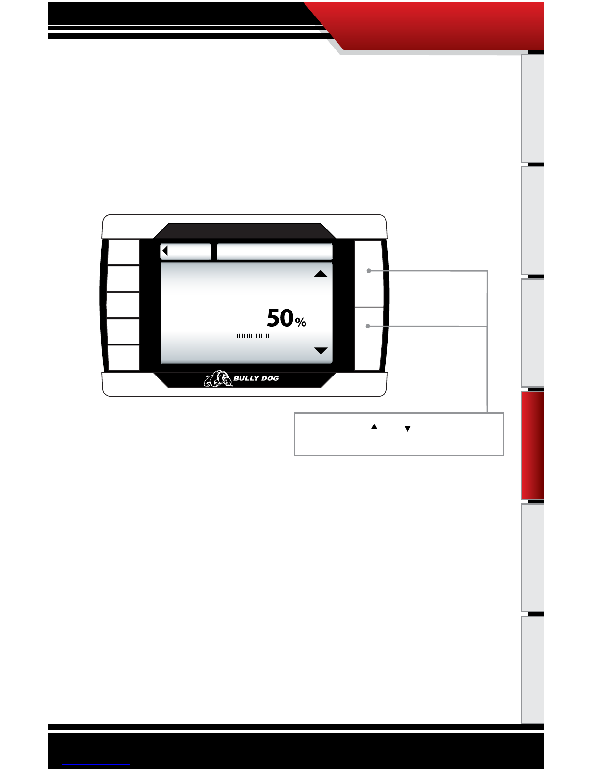
ADJUST BACKLIGHT
Highlight either keypad or screen and use the up and down buttons to adjust the lighting
to your preference.
Go Back
BACKLIGHTING
to User Opts
0 50 100
Screen
Key Pads
Brightness 50%
Brightness 100%
Keypad Backlight
Select 0 to 100% using and
to set desired light level
Go Back
BACKLIGHTING
to User Opts
0 50 100
Key
Brightness 100%
Brightness 100%
Screen Backlight
Select 0 to 100% using and
to set desired light level
Screen
Use this button to select the Key Pads option.
Use this button select the ‘Screen’ option.
Use these
buttons to
adjust the
backlight
brightness
level.
OPERATING INSTRUCTIONS
Operating Instructions
Page 48

47
Introduction Parts Description PMT Installation Internet Updates Appendix
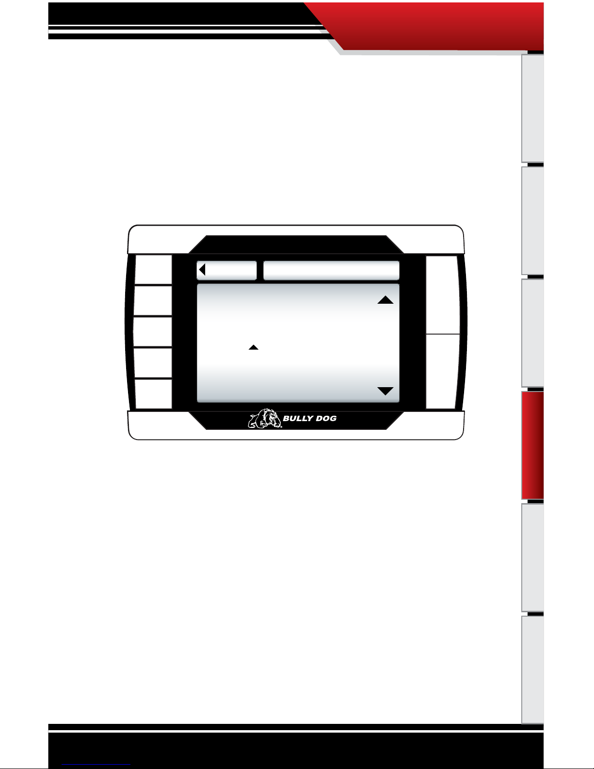
ADJUST BACKGROUND COLOR
Use the up and down buttons to select a background color. The PMT background will preview each color background as you scroll up and down through the color options. When
the preferred color is highlighted, exit the color menu to select the color.
Go Back
COLOR SETUP
to User Opts
Background
Black
Background
Use the up and down arrows
to change the gauge function
Black
Red
Use the large Up Down Buttons to scroll up and
down through the color options.
Red
Orange
Yellow
Yellow Green
Green
Light Blue
Blue
Indigo
Violet
Gold
Clay
Brown
Olive
Sky
Black
Available Color Backgrounds
OPERATING INSTRUCTIONS
Operating Instructions
Page 49
48
Introduction Parts Description PMT Installation Internet Updates Appendix
ADJUST VOLUME SETTING
To adjust the sound volume for button feedback and voice calls, simply scroll up and down
to adjust the volume from zero to one hundred.
Go Back
SET VOLUME
to User Opts
0 50 100
Volume
Use the up and down arrows
to adjust the volume
Use the large Up Down Buttons to scroll up and
down through the color options.
OPERATING INSTRUCTIONS
Operating Instructions
Page 50

49
Introduction Parts Description PMT Installation Internet Updates Appendix
ADJUST TIME AND DATE SETTING
When the correct time is specified use the go right button to highlight SET, and then press
the up button to set either the time or date.
Go Right
Go Left
Go Back
SET CLOCK
Date
Time
Date
Use the Up and Down Arrows
to Change time/date
to User Opts
Month Day Year
Go Right
Go Left
Go Back
SET CLOCK
Time
Date
Time
Use the Up and Down Arrows
to Change time/date
to User Opts
Press Go Left to move the selection box to
the left.
Use these buttons to select
either time or
date in order
to change that
information.
Press Go Right
to move the
selection box
to the right.
To set Time & Date highlight SET and press the
‘up button.
Use these
buttons to
move the
selected
values up
and down.
OPERATING INSTRUCTIONS
Operating Instructions
Page 51
50
Introduction Parts Description PMT Installation Internet Updates Appendix
RESET TO DEFAULT SETTING
To reset the PMT to Bully Dog factory settings press the up button to select yes, to keep current
settings back out of this menu by pressing the go back button or by pressing the down button
to select no.
Go Back
GO TO DEFAULT
to user opts
Selecting YES will reset user
preferences to factory set values.
Are you sure you want to do this at
this time? ( for YES)
yes
no
OPERATING INSTRUCTIONS
Operating Instructions
Page 52

51
Introduction Parts Description PMT Installation Internet Updates Appendix
DEFUELING PARAMETERS
Set up defueling parameters based on a number of dierent vehicle parameters. In this menu
you can also turn vehicle parameters o. The defueling parameters available are vehicle specic, so not all defueling parameters are available for every make and model.
Below is a list of all of the defueling capabilities for the PMT. All defueling options can be activated at
the same time, all can be turned o, or a mix of on and o. Each defueling option is adjusted individually to be on or o and set to a particular defueling temperature.
Engine Coolant Temp Level
Boost Level
Go Back
DEFUEL MENU
Transmission Temperature
Oil Temperature
Pyro 1 Temperature Level
Pyro 2 Temperature Level
to Main Menu
Setting: 600˚F
Setting: 1250˚F
Setting: 210˚F
Setting: 260˚F
Setting: 210˚F
Setting: 23PSI
Use the Up Down Buttons to scroll up and
down through the dierent sub menu items.
Press to enter set up menu for defuel items.
Default Defueling Settings
Pyro 1 Temperature Level 1250˚F
Pyro 2 Temperature Level OFF
Engine Coolant Temp Level 220°F
Boost Level OFF
Transmission Temp Level OFF
Oil Temperature OFF
OPERATING INSTRUCTIONS
Operating Instructions
Current setting are displayed in Defuel Menu
Page 53
52
Introduction Parts Description PMT Installation Internet Updates Appendix
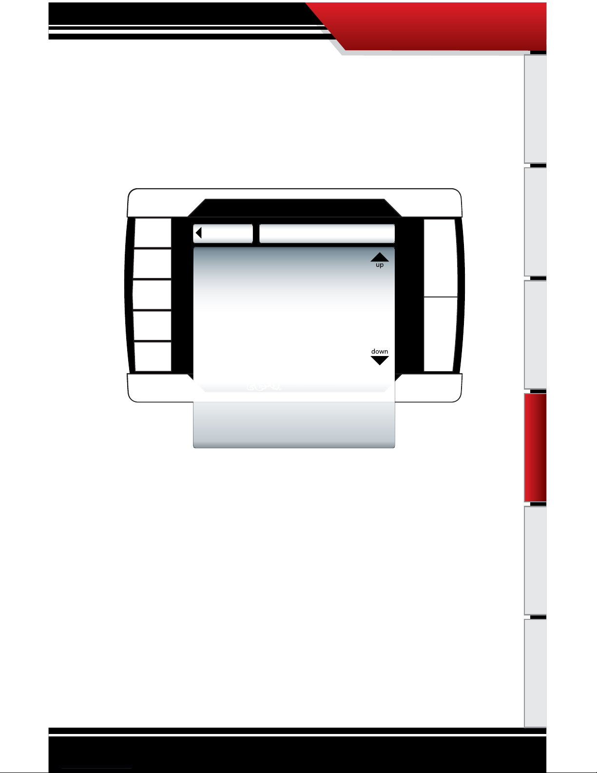
SET DEFUEL LEVELS:
When entering a setup menu for any of the defuel options the menu will have a list of defuel levels
to select from based on that specic defuel parameter. The selected value is displayed on the left, to
select a defuel level you need only highlight the amount and then exit the setup menu. To turn any
particular defuel parameter o press the bottom left button.
Go Back
PYRO1
to Defuel Menu Set Deful Level
The sel ected de fuel val ue
for PYR O 1 is d isplayed
in the box bel ow:
Selected
OFF
DEFUEL OFF
DEFUEL ON
Go Back
PYRO1
to Defuel Menu Set Deful Level
up
down
Defueling Levels
1250
1300
1350
1400
1450
1500
1550
1600
The selected Defuel value
for PYRO 1 is displayed
in the box below:
Selected
1400º F
DEFUEL ON
DEFUEL OFF
Use the large Up Down Buttons to scroll up
and down through the dierent sub menu
items.
Use this button to turn the defueling on.
Use this button to turn the defueling off.
OPERATING INSTRUCTIONS
Operating Instructions
Page 54
53
Introduction Parts Description PMT Installation Internet Updates Appendix
TRANSMISSION TUNE: FORD 6.0L ONLY
This allows you to set a specic transmission tune style for each on-the-y power setting. There
are three transmission tune styles available: stock, smooth, and aggressive. Not all of the tunes
are available for every power setting.
Stock
Go Back
TRANSMISSION TUNE
Tow
PERFORMANCE
Smooth
Stock
Extreme
Use the Up and Down Arrows
to Change the tranny tune.
Smooth
Aggressive
EXTREME
Aggressive
Use these buttons to select the power level for
which you want to set the transmission tune.
Use the Up and Down buttons to highlight
the transmission tune that you would like to
Use for each power level.
Notice that upon entering the transmission tune menu that, Extreme, is highlighted in black. When
a Power level location is selected it is highlighted in black on the left and it also appears above the
transmission tune selection box.
OPERATING INSTRUCTIONS
Operating Instructions
Page 55

54
Introduction Parts Description PMT Installation Internet Updates Appendix
ADJUST TIRE SIZE
The tire size function allows you to adjust the speed that the PMT will display in one of the
gauge locations to account for larger or smaller than stock tire sizes. The range of tire sizes that
the PMT will adjust for starts at 28” and goes up to 39” and it adjusts in increments of .25”.
* Accurate only if
ECM tire size
setting are at
default factory
values.
DEFAULT
31.0
31.25
31.50
32.0
32.25
32.50
32.75
DEFAULT
Use the Up and Down buttons to scroll
through the available tire sizes; highlight the
tire size that ts what is currently mounted
on the vehicle to display the speed accurately.
Notice that the selected tire size is displayed
in the box on the left side of the screen.
Once the correct speed is highlighted simply
press the go back button to exit. Your selection will automatically be saved.
Notice that if a speedometer calibration has been performed on the vehicle that it will aect the
value displayed on the PMT.
OPERATING INSTRUCTIONS
Operating Instructions
Default setting:
The default setting reads the speed directly o of the vehicle’s computer. Use this setting if you have
already calibrated the speedometer for larger or smaller aftermarket tires.
Page 56
55
Introduction Parts Description PMT Installation Internet Updates Appendix
DIAGNOSTICS
This sub menu allows you to check vehicle Diagnostic Trouble Codes (DTCS). Upon entering this
menu, the PMT will automatically begin to check the vehicle for DTCs and it will then display
those DTCs on the PMT screen. Once it displays the DTCs value and description on the screen it
will allow you to erase the DTCs from the vehicle.
If no DTCs are displayed you can simply press the Go Back button to return to the main menu.
THE SD CARD MUST BE INSERTED IN THE SIDE OF THE PMT TO READ AND ERASE DTCS
DTC
Diagnostic Trouble Codes
Establishing communication
with the vehicle
Go Back
DTC
to Main Menu
Diagnostic Trouble Codes
There are no DTCs Detected
OPERATING INSTRUCTIONS
Operating Instructions
Page 57
56
Introduction Parts Description PMT Installation Internet Updates Appendix
SHOW SETTINGS:
The Show Settings Menu will allow you to see vehicle information and also defuel settings. See
the diagram below to see everything that is listed in this menu.
Go Back
SETTINGS
to Main Menu
Vehicle Info:
Vehicle: ‘06 Ford Power Stroke
Vin#: 123456789101112131415
Part#:
PMT Info:
HV: 2.2
SV: 1.0.0.2
Serial:
Download: Not Installed
Defuel:
Pyro 1: 1250º
Pyro 2: OFF
Coolant: 230º
Boost: OFF
Transmission: 260º
Oil: OFF
OPERATING INSTRUCTIONS
Operating Instructions
Page 58

57
Introduction Parts Description PMT Installation Internet Updates Appendix
UPDATE PMT SOFTWARE
This sub menu is only used when a new internet update becomes available through our Update
Agent, in which case you need to remove the SD Card and update it with the new information
provided by the Update Agent. Once an SD Card has updated le information can be put back
into the PMT and the PMT can be updated by entering into this sub menu.
Some updates will require that the PMT be returned to stock before the SD Card is removed and updated by the
Update Agent. See the Version Information section in the Internet Updates portion for instruction on when it is
necessary to return to stock and when updates can be performed without returning to stock.
Go Back
UPDATE PMT
to Main Menu
Reading File...
Verify Checksum
Checksum Verified.
New Image Found.
Do you want to load this file now?
(Press Y to complete update.)
YES
UPDATE:
UPDATE PMT
Loading application file into the memory.
Screen will darken and the keys
will blink for 3 seconds.
So not Unplug or cycle key.
OPERATING INSTRUCTIONS
Operating Instructions
THE SD CARD MUST BE INSERTED IN THE SIDE OF THE PMT TO UPDATE THE PMT SOFTWARE
Page 59

58
Introduction Parts Description PMT Installation Internet Updates Appendix
Go Back
UPDATE PMT
to Main Menu
SD card not found.
Press a key to continue.
Go Back
UPDATE PMT
to Main Menu
Reading File...
Verify Checksum
Checksum Verified.
Same Image Loaded.
NO SD CARD NOTICE: Screen capture below illustrates what will be seen on the screen when you try to update
the PMT software without an SD card inserted.
IDENTICAL FILE NOTICE: This is what you will see when the information on the SD card matches the current le
information on the PMT. If you are attempting to update the PMT, check the software versions and try again.
OPERATING INSTRUCTIONS
Operating Instructions
Page 60

59
Introduction Parts Description PMT Installation Operating Instructions Appendix
PMT INTERNET UPDATE INSTRUCTIONS
Internet Updates: There are three sections in the internet updates portion of this manual, each section is
important to understanding and performing internet updates on the PMT.
• SECTION 1: PMT VERSI
ON INFORMATION: Before performing an internet update it is
important to know how the version system works. You may or may not have to download the
PMT/vehicle back to stock before performing an internet upgrade based on the version number.
• SECTION 2: THE
UPDATE AGENT: This is Bully Dog’s exclusive software program developed to
update Bully Dog products via the internet. This software is required to update the PMT. This section will explain how to use the Update Agent to check product version info and where to obtain
the Update Agent.
• SECTION 3: THE
UPDATE PROCESS: This section explains how to update the PMT step by
step using the SD card and the SD Card reader.
INTERNET UPDATES
Internet Updates
Page 61

60
Introduction Parts Description PMT Installation Operating Instructions Appendix
SECTION 1: PMT VERSION INFORMATION
You may have to download the PMT/vehicle back to stock before performing an internet update.
The change in the version number for any new update issued on the Update Agent can be checked
and compared to the last version to tell if the vehicle needs to be returned to stock before an update
is performed.
The PMT software versions contain four digits as seen below:
1.0.0.0
Go Back
SETTINGS
to Main Menu
Vehicle Info:
Vehicle: ‘06 Ford Power Stroke
Vin#: 123456789101112131415
Part#:
PMT Info:
HV: 2.2
SV: 1.0.0.2
Serial:
Download: Not Installed
Defuel:
Pyro 1: 1250º
Pyro 2: OFF
Coolant: 230º
Boost: OFF
Transmission: 260º
Oil: OFF
Go to the Show Setting Menu to view current
installed PMT software version.
If any of the rst three digits change in the PMT,
then the PMT/vehicle must be downloaded back
to stock before an internet update is possible.
If the fourth digit is the only digit
that changes on a newly issued
PMT version then it is not necessary to return the vehicle to stock.
INTERNET UPDATES
Internet Updates
Page 62

61
Introduction Parts Description PMT Installation Operating Instructions Appendix
SECTION 2: THE UPDATE AGENT
The PMT can only receive internet updates through the Update Agent. Therefore, internet updates
must be performed on a PC with a strong internet connection.
To install the Update Agent on a PC visit: www.bullydog.com/download_center.php . This address will take
you to the Bully Dog download center where a free copy of the Update Agent can be downloaded.
Besides updating the les on the PMT SD Card, the Update Agent can be used as a resource for checking
software version information for the PMT. This information can be used to determine if an internet update is
necessary for your particular vehicle.
USE THE UPDATE AGENT TO IDENTIFY THE LATEST PMT SOFTWARE VERSION:
To identify the latest software version available through the Update Agent, maximize the Update Agent to
see the interface. Click on the View menu item on the Update Agent interface and then click on Latest Product
Versions in the View menu. This will open a Notepad le which displays all of the version information on all
of Bully Dog’s electronic products. Use the le to compare the PMT version listed in that le to the version
displayed on the PMT in the Show Settings sub menu.
USE THE UPDATE AGENT TO SEE WHAT CHANGED IN THE BETWEEN PMT SOFTWARE VERSIONS:
To see the version history, which is a summary of changes, scroll over the Version History tab and then select
PMT in the drop down menu. That will then display a summary of changes that have taken place throughout
the life of the PMT based upon version number.
INTERNET UPDATES
Internet Updates
Page 63

62
Introduction Parts Description PMT Installation Operating Instructions Appendix
SECTION 3: THE UPDATE PROCESS
Once you have checked the version history and downloaded the PMT/Vehicle back to stock, if
needed, you are ready to perform the update to get the latest PMT software. Follow the process
listed below to update the PMT software to the latest version.
1. Remove the SD Card from the PMT and gather the SD Card Reader. Insert the SD Card into the SD Card Reader.
2. Plug the SD Card Reader into a PC that has the Update Agent installed and the latest PMT software version
downloaded. Note that the Update Agent will not automatically recognize the SD Card unless it is inserted
into the SD Card Reader before the SD Card Reader is plugged into a PC.
3. Allow the Update Agent at least 10-20 seconds to auto recognize the SD Card. Once the Update Agent
recognizes the SD Card and the Update Agent expands to display the software interface, highlight the PMT
displayed in the devices menu and select Update.
4. With the SD Card updated, rst remove the SD card reader from the PC, then remove the SD card from the SD
card reader and return it to the PMT. Insert the SD Card into the SD Card slot on the PMT.
5. With the PMT docked to the PMT cradle turn the ignition to the on position, but do not start the engine.
6. On the PMT interface, navigate into the Main Menu and select the Update PMT Software sub menu.
7. Follow the screen prompts to update the PMT, do not unplug while performing the PMT update.
8. Once complete, depending on the change in version number, you may now need to install a download back
onto the vehicle.
INTERNET UPDATES
Internet Updates
Page 64

63
Introduction Parts Description PMT Installation Operating Instructions
APPENDIX:
The appendix contains important information for the PMT and is split into ve sections.
• SECTION 1: PYRO
METER CALIBRATION PROCEDURE
• SECTION 2: TRANSMIS
SION RELEARN PROCEDURES: FORD AND GM
• SECTION 3: CUSTO
M APILLAR PART NUMBER INFORMATION
• SECTION 4: TRO
UBLESHOOTING/ERROR CODES
• SECTION 5: FO
RMATTING SD CARD
• SECTION 6: WAR
RANTY/DISCLAIMER
SECTION 1: PYROMETER CALIBRATION PROCEDURE
BEFORE THIS STEP CAN BE COMPLETED, COMPLETELY INSTALL THE PMT AND ALL OF ITS COMPONENTS.
1. Vehicle must be set to Stock HP/TQ levels-meaning no HP/TQ modications of any kind (downloader or plug-in
modules).
2. Engine must be put under full load for as long as possible on the hottest day possible. It is suggested to drive up a
hill or pull a trailer.
3. During a heavy load pull, record the highest reading.
4. Take that reading and add 150° to the high number and that will be your new defuel number that you do not
want to exceed.
APPENDIX
Internet Updates Appendix
Page 65

64
Introduction Parts Description PMT Installation Operating Instructions
SECTION 2: TRANSMISSION RELEARN PROCESS
After completing the download process, it is recommended on a 6.6L Durmax with an automatic Allison and a 6.0L Ford Power Stroke with an automatic Torque Shift transmission, that the transmission be relearned. Relearning the transmission can help the transmission adjust to the higher levels
of power oered by the PMT resulting in a better shifting transmission. Follow the vehicle specic
procedures below to relearn the following transmissions.
GM 6.6L DURAMAX WITH ALLISON TRANSMISSION
1. At a ¼ throttle get up into 5th gear. Once you are in 5th gear, apply light pressure to the brake pedal until the truck
is stopped.
2. At a ½ throttle get up into 5th gear. Once you are in 5th gear, apply light pressure to the brake pedal until the truck
is stopped.
3. At ¾ throttle get up into 5th gear. Once you are in 5th gear, apply light pressure to the brake pedal until the truck
is stopped.
4. At full throttle get up into 5th gear. Once you are in 5th gear, apply light pressure to the brake pedal until the truck
is stopped.
5. Go through the same process with the Tow Haul button on.
FORD 6.0L POWER STROKE AUTOMATIC TORQUE SHIFT TRANSMISSION
1. Come to a complete stop and put the downloader on its highest setting.
2. Moderately accelerate to 55 mph.
3. Allow the vehicle to shift into overdrive and while in overdrive, maintain a speed of 55 mph for 15 seconds.
4. Lightly apply the brake just enough to engage the brake lights, hold brake lights on while maintaining
55 mph for another 15 seconds.
5. Come to a complete stop for 20 seconds.
6. Repeat steps 3 through 5 ve additional times.
7. Drive normally and enjoy.
APPENDIX
Internet Updates Appendix
Page 66

65
Introduction Parts Description PMT Installation Operating Instructions Internet Updates
SECTION 3 CUSTOM A PILLAR PART NUMBER INFORMATION
A-Pillar Pod Mount
DESCRIPTION PART #
A-Pillar Pod Mount ‘03-’07 Ford 31302
A- Pillar Pod Mount ‘03-’07 Dodge Ram 32303
A- Pillar Pod Mount ‘01-’07 GM with Speaker 33303
A- Pillar Pod Mount ‘01-’07 GM without Speaker 33302
APPENDIX
Appendix
Page 67

66
Introduction Parts Description PMT Installation Operating Instructions Internet Updates
SECTION 4: PMT TROUBLESHOOTING
CONDITION POSSIBLE SOURCES ACTION
PMT will not turn on Installation/ Connections
Make sure that the fuse jack is securely fastened to the
fuse socket.
Check that the fuse is working properly.
Make sure that all of the harnesses are properly installed. If
still not working, one of the harnesses could be defective.
Will only display pyrometer Improper Truck Selection
Check and ensure the proper truck is selected.
Make sure you have proper connections everywhere.
Also, make sure that there are no bent pins in any of the
connectors.
Will not adjust horsepower Improper Truck Selection Check and ensure the proper truck is selected.
Back light quit working Loose Connections
Contact Technical Support if the PMT is otherwise functioning normal.
PMT will not display proper
temperature EGTs
Pyrometer Probe
Connections Incorrect
Check the orientation of the Pyrometer connections on
the PCH to ensure that the Pyrometer leads are properly
connected.
For more information on up-to-date troubleshooting guide for the PMT, go to
www.bullydog.com/Product_Updates.php
PMT ERROR CODES:
For
error code information regarding any error codes that appear while operating the PMT visit the
web address below:
www.bullydog.com/PMT_Tech.php
APPENDIX
Appendix
Page 68
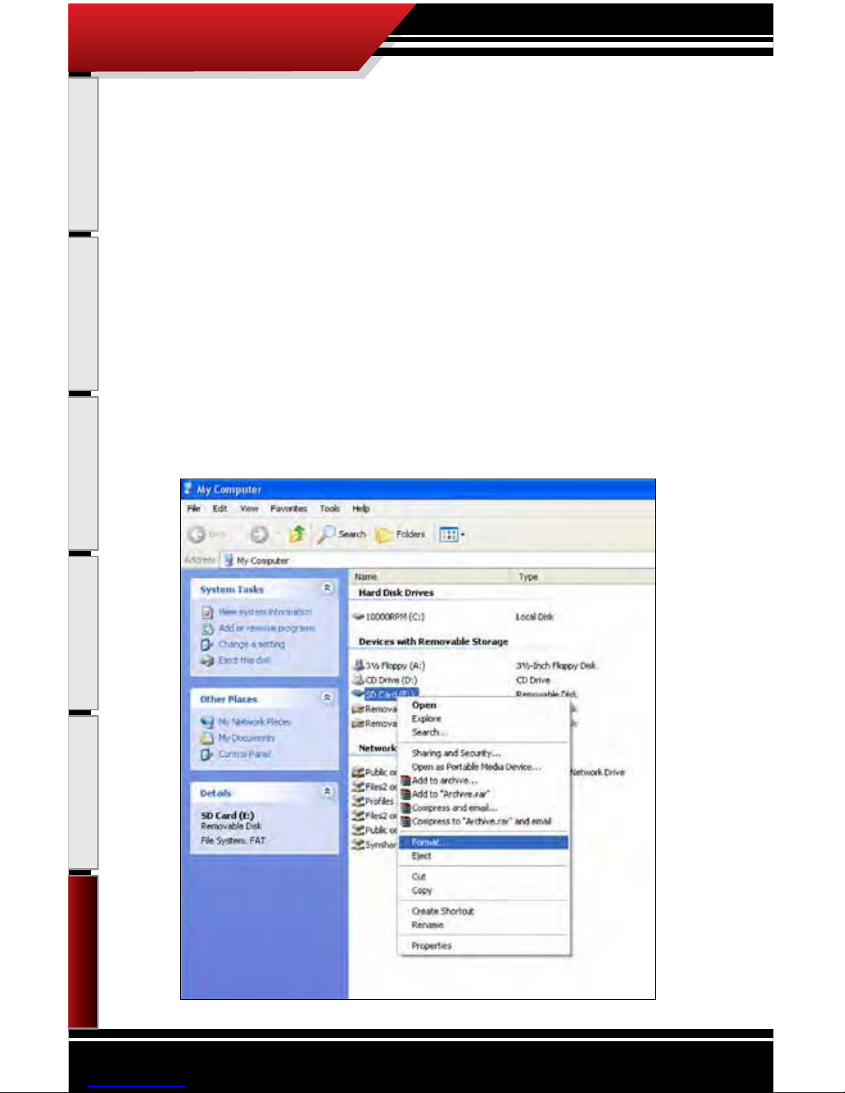
67
Introduction Parts Description PMT Installation Operating Instructions Internet Updates
APPENDIX
Appendix
SECTION 5: FORMATTING SD CARD
The SD card should only be taken out of the PMT to perform internet upgrades. It is the primary
means of performing internet upgrades for the PMT.
In case an SD Card is lost or broken, a new SD Card can be purchased and used to update the PMT.
However, the new card will need to be formatted to work with our internet update software, The
Update Agent. The reason a new SD card needs to be formatted is so that the Update Agent will
automatically recognize that SD Card when the SD card is plugged into a PC. Below are steps and
diagrams showing how to format a new SD Card:
1. Plug the SD Card into a PC via the USB to SD Card Reader.
2. Open the My Computer function in Microsoft windows to see all of the devices and drives on that PC. Find
the new SD Card in the list under the heading, “Devices with removable storage.”
3. Right click on the SD Card to show a drop down menu of options. In the drop down menu click on Format.
Page 69
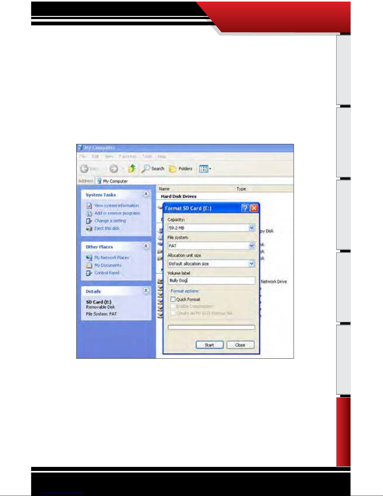
68
Introduction Parts Description PMT Installation Operating Instructions Internet Updates
APPENDIX
Appendix
4. With the formatting dialog box open click the drop down men for “File System.” Highlight and click on FAT.
5. Then change the Volume Label to read “Bully Dog,” by typing it into the dialog box below that title.
6 Click “Start” to reformat the card with the new information.
Page 70

69
Introduction Parts Description PMT Installation Operating Instructions Internet Updates
APPENDIX
Appendix
7. After the reformat process is complete you need to visit our website to download a le that must be saved
to the SD card. Visit http://www.bullydog.com/Updateagent.php and click on the link that says “SD Card
ID le.”
8. When prompted save this le to the SD card.
9. Now unplug the card reader and plug it back into the PC and the Update Agent should recognize this SD
Card.
Now whenever this card is plugged into any PC that has the Bully Dog Update Agent installed the
Agent will automatically recognize the SD Card.
Page 71

70
Introduction Parts Description PMT Installation Operating Instructions Internet Updates
SECTION 6: WARRANTY & DISCLAIMER
REMEMBER, THIS IS A PERFORMANCE PRODUCT, USE AT YOUR OWN RISK.
This product is not intended to be used to break the law.
Do not use this product until you have carefully read the following agreement. This agreement sets forth the terms and conditions
for the use of this product. The installation of this product indicates that the buyer has read and understands this agreement and
accepts the terms and conditions. Never exceed recommended vehicle or tire top speed ratings.
DISCLAIMER OF LIABILITY
Bully Dog Technologies, LLC. Its distributors, jobbers, and dealers (hereafter Seller) shall be in no way responsible for the product’s
proper use and service. THE BUYER HERBY WAIVES ALL LIABILITY CLAIMS.
The Buyer acknowledges that he is not relying on the Sellers skill or judgment to select or furnish goods suitable for any particular
purpose and that there are no liabilities which extend beyond the description on the face hereof, and the Buyers hereby waivers
all remedies or liabilities expressed or implied, arising by law or otherwise, (including without any obligation of the Seller with
respect tness, merchantability and consequential damages) or whether or not occasioned by the Seller’s negligence.
The Seller disclaims any warranty and expressly disclaims any liability for personal injury or damages. The Buyer acknowledges
and agrees that the disclaimer of any liability for personal injury is a material term for this agreement and the Buyer agrees to
indemnify the Seller and to hold the Seller harmless from any claim related to the item of the equipment purchased. Under no
circumstances will the Seller be liable for any damages or expenses by reason of use or sale of any such equipment.
The Seller assumes no liability regarding the improper installation or misapplication of its products. It is the installer’s responsibility to check for proper installation and if in doubt contact the manufacturer.
The Buyer is solely responsible for all warranty issues from the manufacturer.
LIMITATION OF WARRANTY
BULLY DOG TECHNOLOGIES, LLC. (Hereafter “Seller”) gives Limited Warranty as to description, quality, merchantability, and tness
for any particular purpose, productiveness, or any other matter of Seller’s product sold herewith. The Seller shall be in no way responsible for the products proper use and service and the Buyer hereby waives all rights other than those expressly written herein.
This warranty shall not be extended, altered or varied except be a written instrument signed by Seller and Buyer.
The Warranty is Limited to one (1) year from the date of sale and limited solely to the parts contained within the products kit. All
products that are in question of Warranty must be returned prepaid to the Seller and must be accompanied by a dated proof of
purchase receipt. All Warranty claims are subject to approval by BULLY DOG TECHNOLOGIES, LLC.
Under no circumstances will the Seller be liable for any labor charged or travel time incurred in diagnosis for defects, removal, or
reinstallation of this product or any other contingent expenses.
Under no circumstances will the Seller be liable for any damage or expenses incurred by reason of the use or sale of any such equipment.
IN THE EVENT THAT THE BUYER DOES NOT AGREE WITH THIS AGREEMENT: THE BUYER MAY PROMPTLY RETURN THIS PRODUCT, IN
A NEW AND UNUSED CONDITION, WITH A DATED PROOF OF PURCHASE TO THE PLACE OF PURCHASE WITHIN THIRTY (30) DAYS
FROM DATE OF PURCHASE FOR A FULL REFUND.
THE INSTALLATION OF THIS PRODUCT INDICATES THAT THE BUYER HAS READ AND UNDERSTANDS THIS AGREEMENT AND ACCEPTS
ITS TERMS AND CONDITIONS.
APPENDIX
Appendix
Page 72
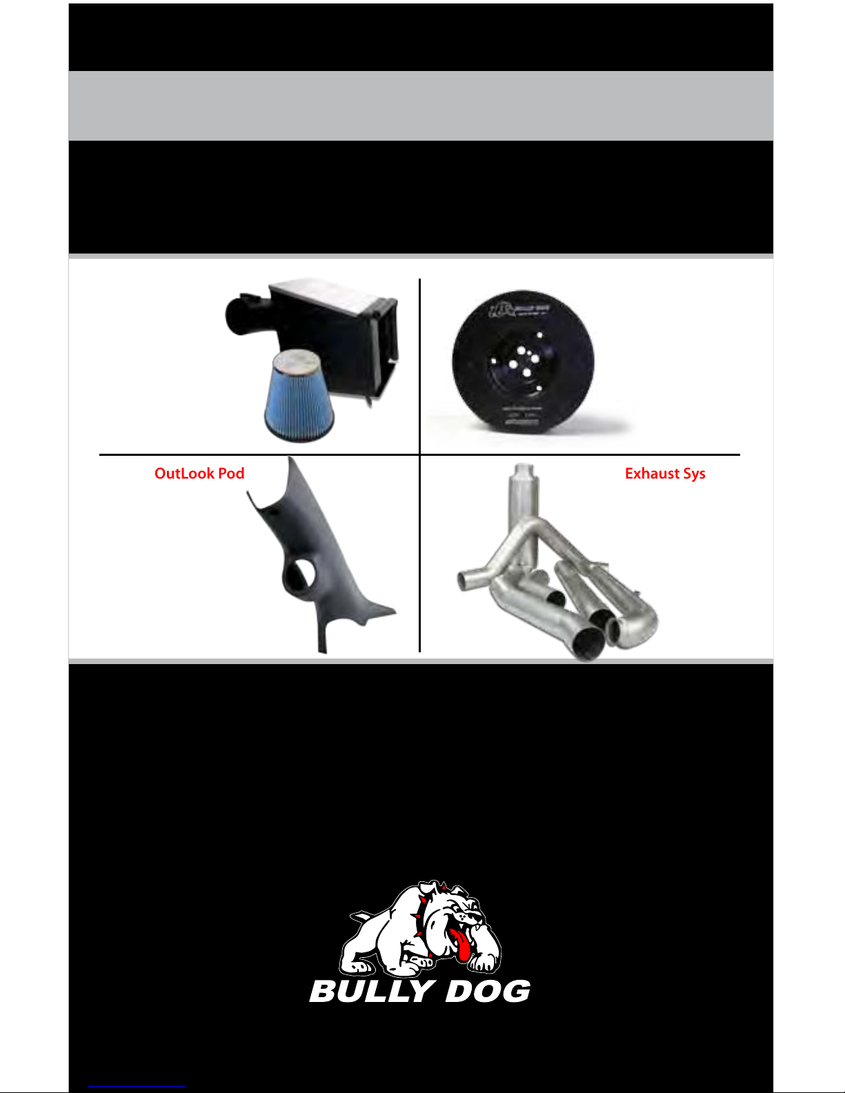
For Free Technical Support
Call: 866-bullydog (866-285-5936)
®
See more at: bullydog.com
Doc.# BD46010 v1.0.1
For a full listing of Diagnostic Trouble Codes go to: www.bullydog.com/DTC.php
Fluid Damper
Exhaust SystemsCustom OutLook Pod
Cold Air Intakes
UNLEASH THE POWER
WITH BULLY DOG PERFORMANCE PRODUCTS
Bully Dog Technologies, LLC is a team built on integrity that is dedicated to leading the vehicle performance
industry with an uncompromising code of ethics demonstrated in the soundness of its employees, excellent
customer service and superior products.
 Loading...