

Page 1

INSTALLATION
Part 1
Physical Installation
PHYSICAL INSTALLATION ............................................................................PGS. 515
SECTION 1: Parts Included ................................................................................. PG.5
SECTION 2: Parts Description .........................................................................PGS. 69
Watchdog Head Unit .......................................................................................pg. 6
OBDII Adapter Plug .........................................................................................pg. 7
Main Wiring Harness .......................................................................................pg. 8
Power Wire .....................................................................................................pg. 8
Micro SD Card ..................................................................................................pg. 9
Universal Windshield Mount ............................................................................pg. 9
Mini USB Cable ................................................................................................pg. 9
SECTION 3: Installation Overview ...................................................................... PG.10
SECTION 4: Installation .............................................................................. PG.1115
Part 1: Connecting the OBDII Adapter to the OBDII Port ..................................pg. 12
Part 2: Connecting the Power Wire .................................................................pg. 13
Part 3: Running the Main Wire Harness ..........................................................pg. 14
Part 4: Mounting the Watchdog using the windshield mount ......................... pg.15
4
Page 2
INSTALLATION
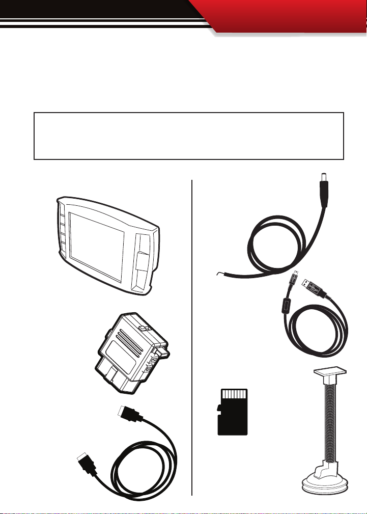
SECTION 1: Parts Included
The list below includes the major parts included in your Watchdog package. The tools list
indicates all of the tools necessary to complete the Watchdog install.
TOOLS NEEDED
• Fuse Puller
• Voltage Meter (optional)
THE WATCHDOG HEAD UNIT
OBDII ADAPTER PLUG
MAIN WIRE HARNESS
EXTRA PARTS (optional)
• Fuse Jack
• Spade connector
THE POWER WIRE
MINI USB CABLE
MICRO SD CARD
WINDSHIELD MOUNT
5
Page 3
INSTALLATION
SECTION 2: Parts Description
This section describes each of the parts in the Parts List, each description provides a physical set of attributes and a purpose for each part.
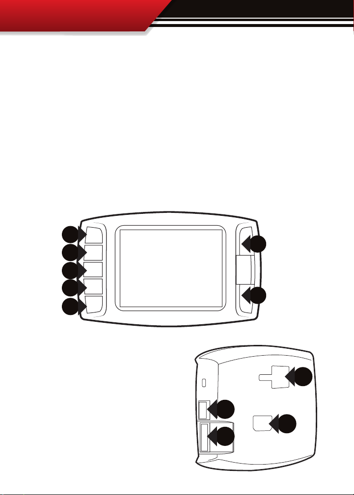
THE WATCHDOG HEAD UNIT:
The Head Unit is the interface through which all operating functions take place including:
Monitoring functions, the Driving Coach feature, and performance tests.
Watchdog Front Side: The Watchdog has seven capacitive touch buttons. Capacitive touch buttons are a
button style that is sensitive to the presence of your nger. Capacitive buttons do not need to be pushed,
only touched to activate. The Watchdog interface features a 2.4” LCD screen.
2.4” LCD
Watchdog Parts (Back side):
1. T-slot Mount Socket, this will work with a large range of
o the shelve mounting options.
2. Main harness port, elec tronic port for the main harness
with HDMI style plugs ends.
3. Micro SD Card Slot
4. Mini USB port
6
1
4
2
3
Page 4
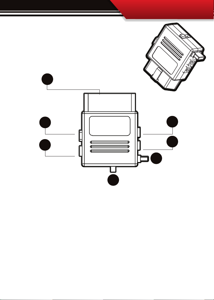
OBDII ADAPTER PLUG
The OBDII Adapter is a communication hub for the Watchdog.
The OBD ll Adaptor plugs directly into the vehicle OBD ll port. The
diagram below illustrates all of the OBDII parts and ports.
1
INSTALLATION
2
3
5
6
7
4
1. OBD ll Male End: this is the part of the adapter plug that plugs into the vehicle OBDll port.
2. Main Harness port: the main harness will plug into the Watchdog and into this port during installation.
3. Power wire port: the power wire will run from this port to the vehicle fuse pox during installation.
4. Power Supply Switch: use this switch to change power from running o of the Power Wire to OBD ll power
as a power supply for the Watchdog.
5. Four Pin USB: This port is used if a Bully Dog pyrometer kit is purchased for the Watchdog.
6. Five Pin USB
7. Adapter Plug 2 amp fuse, (do not unplug unless replacing)
7
Page 5

INSTALLATION
WATCHDOG MAIN WIRE HARNESS
The main harness connects the Watchdog to the OBD ll Adapter Plug and acts as the main line
of communication for the Watchdog. This harness is 5 ft in length.
POWER WIRE
The Power wire connects the OBD ll Adaptor Plug to the vehicle fuse box
to supply power to the Watchdog.
8
Page 6

MICRO SD CARD
The Micro SD Card holds all of the electronic
les necessary to properly start up the
Watchdog, the SD card must be installed
into the micro SD card slot on the side of the
Watchdog at all times. The micro SD card
will even remain in the SD card slot during
internet updates.
UNIVERSAL WINDSHIELD MOUNT
This universal windshield mount is used to install the Watchdog rmly
onto the windshield, it is a suction cup mount that will work on any
vehicle windshield. We also oer a pillar pod mounting style, check our
web site for details.
INSTALLATION
MINI USB CABLE
The mini USB cable is a standard o the shelf mini
USB cable. It serves two purposes for the WatchDog:
1. Internet Updates
2. Downloading performance tests to a PC from the
WatchDog.
9
Page 7

INSTALLATION
Watchdog & Windshield Mount
OBDII Adapter Plug
OBDII Port
Power Wire
Fuse Box
Fire wall grommet
(optional)
SECTION 3: Installation Overview
The installation overview diagram below illustrates a properly installed Watchdog. This
overview is meant to help reference the general location of installed parts and pieces of the
Watchdog. Note that some fuse boxes will be located inside the cab of the vehicle and will
not require that the power wire go through the vehicle fire wall. For ease of installation,
look for an in cab fuse box before going through the fire wall.
10
Page 8

INSTALLATION
SECTION 4: Installation
These installation instructions are split into four easy installation parts or activities. Each
part contains a small set of instructions to complete the part. Complete each part in order in
which they appear in this section for the easiest installation of this product. The installation
tasks start on the following page.
QUICK TIP: be sure that the switch on the OBD ll adapter plug is in the “down,” position. This will ensure
that the WatchDog is running o of power supplied from the power wire. The end result is that the Watch
Dog will only turn on when the ignition is turned on.
Reference “Notch” is up
Switch is down
11
Page 9

Possible OBDII Port Locations
(location may vary)
OBDII Plug
Main Cable
Power Wire
OBDII Adapter Plug Installation Diagram
GT
INSTALLATION
PART 1: CONNECT THE OBD ll ADAPTER TO THE VEHICLE OBD ll PORT
This part involves locating the vehicle’s OBD ll port and then simply plugging the OBD ll Adapter Plug
into the OBD ll port.
1. As the illustration below shows, OBD ll ports are always located somewhere under the drivers side
dash. The OBD ll port is a male receiver that will have the same shape as the end of the OBD ll Adaptor
plug.
2. Once the OBD ll port is located, then simply plug the OBD ll Adaptor plug into the OBD ll port.
12
Page 10

INSTALLATION
PART 2: INSTALLING THE POWER WIRE
Part 2 involves locating the correct fuse within the vehicle fuse box, and connecting the power wire
from the OBD ll Adaptor plug to the fuse in the fuse box.
Pre Installation: Locate the vehicle fuse box; the vehicle owners manual will indicate where the fuse box is
located within the vehicle. Open the fuse box and identify a fuse that has “key on power.” To identify the correct
fuse, nd an accessory fuse using the fuse diagram in the vehicle owners manual. If the vehicle manual does
not help identify an accessory fuse use a voltage meter to identify a fuse that supplies power only when the key
is in the on position.
Installation:
1. See the diagram to the right, simply plug the end of the power wire into the OBD
ll block before running the opposite end to fuse box.
Quick Tip: For the cleanest install of the power wire to a fuse
location use a spade connector and a fuse tap even though you
could just stu the Power wire into the fuse hole.
2. Run the end of the wire to the location of the fuse box. It may be necessary to go through the re wall to get
to the fuse box, if this is the case it may be easier to run through an existing grommet rather than drilling a new
hole.
3. Prepare the end of the power wire by attaching a spade connector to the end of the wire.
4. Remove the selected fuse from its location and then place a fuse tap that is made for that size of fuse
into that selected fuse location along with the original fuse.
5. Connect the spade connector to the end of the fuse tap.
6. Use zip ties to secure any loose wire left hanging from excess slack in the power wire.
13
Page 11

OBDII Plug
Main Cable
Power Wire
OBDII Adapter Plug Installation Diagram
Watchdog
INSTALLATION
INSTALLATION
PART 3: RUN WATCHDOG MAIN WIRE HARNESS
In this section you will connect the Watchdog Main Harness to the OBD ll Adaptor and then run
the other end of the main harness up the side of the vehicle dash and connect it to the back of
the Watchdog.
1. Plug one end of the Main Harness into the Main Harness port on the OBD ll adapter plug.
2. Run the other end of the harness up through the vehicle dash on the driver’s side so that the
end of the harness emerges from the dash near the vehicle A-pillar. It may be necessary to temporarily remove the vehicle weather stripping and dash panel to achieve an installation where
the Main Harness cannot be seen when the driver’s door is opened.
3. Plug the Main Harness into the back side of the Watchdog, make sure that there is enough
slack in the main harness to accommodate mounting the Watchdog.
14
Page 12
INSTALLATION
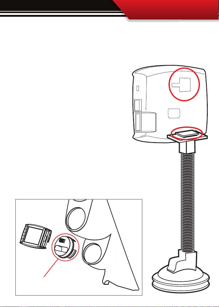
PART 4: MOUNTING THE WATCHDOG
The nal step to installation is mounting the Watchdog to the windshield using the universal
windshield mount.
1. Locate the T-shaped mount socket on the back side of
the Watchdog.
2. Notice that the top of the universal mount will t
into T-shaped socket and slide forward to secure the
Watchdog to the mount.
3. With the Watchdog connected to the mount use the
windshield mount to secure the Watchdog to the windshield. Be sure that the position of the Watchdog does
not obstruct the view of the road or distract the driver
from their primary responsibility, which is careful driving.
Also available is our 2 1/16” universal gauge mount.
Available on our website or through a Bully Dog Dealer.
PN: 30420
15
 Loading...