

Page 1

OWNER’S MANUAL
Nitrous Kit
Part #47000
Page 2
NITROUS KIT
Introduction
The Bully Dog Nitrous Kit allows you to control an
electromechanical solenoid with a GT™ or WatchDog™; it
automatically activates the solenoid if adjustable conditions
like throttle position, rpm and/or speed are met.
Table of Contents
Parts ..................................................................... 1-2
Physical Installation .............................................. 2-4
GT/WatchDog Setup ............................................ 5-6
Menu Blowout ...................................................... 7
Contacting Technical Support.............................. 8
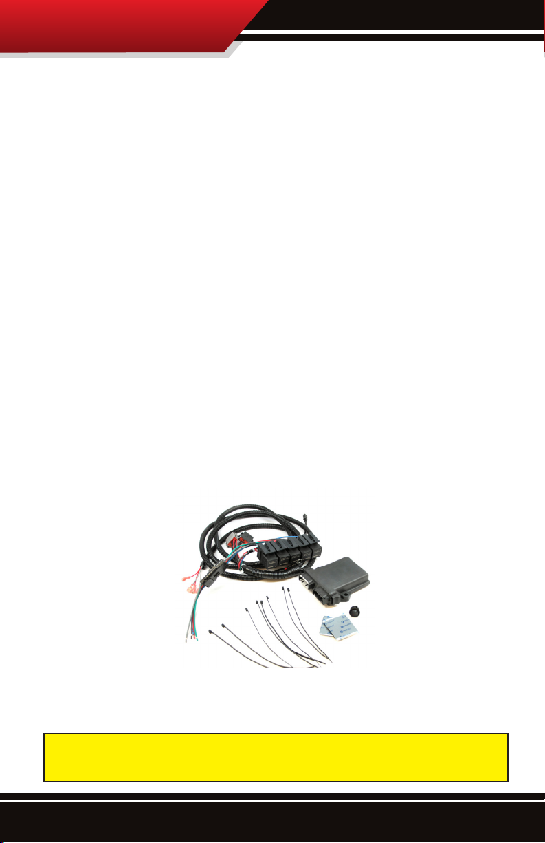
Parts Included
Control Module ....................................................(47020)
Wiring Harness .................................................... (47020-98)
Master Switch ...................................................... (47020-6)
Hook and Loop Fastener ..................................... (40390-94)
Zip ties ................................................................. (1-NYTIE8)
Fuse Tap ............................................................... (PART #)
Tools Needed
• Wire crimper
Up to ve standard wire crimps are also required for
installation; the crimps are not included in the Nitrous Kit.
1
Page 3
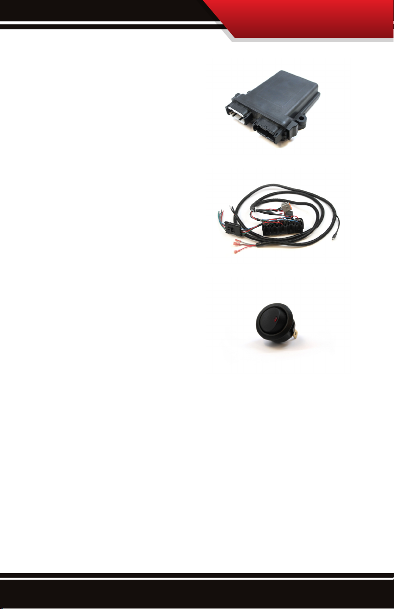
Parts Description
Control Module
The control module interprets
the signals from the GT or
WatchDog and controls the
solenoids.
Wiring Harness
The wiring harness contains
multiple wires and connects all
of the parts of the Nitrous Kit
with the vehicle and the GT or
WatchDog.
Master Switch
A safety measure, the master
switch will turn the Nitrous Kit
o regardless of key position
and GT or WatchDog settings.
NITROUS KIT
Installation
1. Locate a key-on fuse.
‣ It only has power when the key is in the “on” (or
“run”) position.
‣ Use a 12 volt test light or your vehicle owner’s
manual to locate one.
‣ 12 volts at 15 – 20 amps.
2. Choose the control module location:
‣ Away from extreme heat and moving parts
‣ All wires must reach and connect without straining
2
Page 4
NITROUS KIT
3. Mount the control module (use the hook and loop
fastener and/or zip ties to secure it in place).
4. IMPORTANT: Before beginning installation, disconnect
your battery at the negative terminal. Failure to
disconnect the battery could result in personal injury
and/or damage to your vehicle.
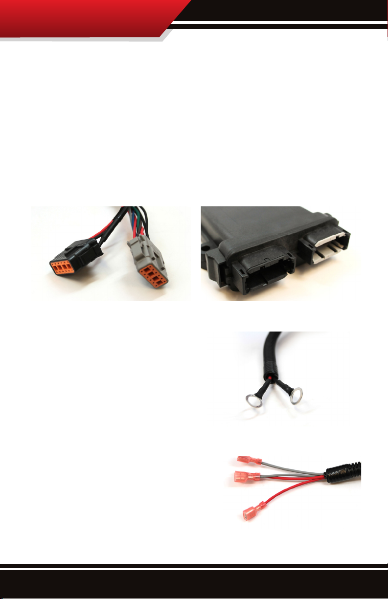
5. Connect the wiring harness to the control module.
‣ Plug set A
‣ The connections are color coded
(black to black and gray to gray).
A
6. Connect the ground wire to the vehicle frame.
‣ Wire C (black wire).
‣ Use the designated
ground bolt.
‣ If the designated
ground bolt is not
available, use a
stock frame bolt.
7. Connect the power wires:
‣ Wire D connects to the
key-on fuse located in
step 1.
‣ Wire B connects to the
positive battery terminal.
3
B C
E & F
D
Page 5

NITROUS KIT
8. Install the Master Switch.
‣ Make sure the switch is in the
OFF position.
The Master Switch should remain in
the OFF position until the Nitrous Kit
installation is complete.
a. Connect the two silver wires (E
& F) to the silver prongs on the switch.
b. Connect the COLOR battery power wire to the gold
prong on the switch.
9. Connect the Mini-USB cable to
the adapter plug on the GT or
WatchDog.
‣ Do not connect it directly to
the GT or WatchDog.
10. Connect the solenoids
to the wiring harness.
‣ Wire set G
‣ The wires are
color-coded:
G
◦ Gray: Master Relay
◦ Blue: Relay 1
◦ Brown: Relay 2
◦ Red: Relay 3
◦ Green: Relay 4
‣ Use standard
crimp connectors.
11. Reconnect the battery.
12. Set up the GT or WatchDog (see pages 5-6).
CAUTION! Prevent possible
engine damage by keeping
track of which relay wire
is used to connect each
solenoid.
4
Page 6

NITROUS KIT
GT/WatchDog Setup
Control the Nitrous Kit with a Bully Dog GT or WatchDog unit;
congure up to ve dierent setting combinations (stages).
A stage will only activate when the vehicle reaches both the
parameter range (Pyrometer temperature, speed, boost or
RPM) and the throttle position that are selected for that stage.
To support the Nitrous Kit, all GTs and Watchdogs must be updated to
software version 1.1.4.3 or newer.
See page 7 for a menu blowout.
1. Go to the Main Menu
(top left button).
2. Select Nitrous/Methanol Setup.
3. Select the stage (1-5).
Go Back
NIT/METH SETUP
to Main Menu
Stage 1
Stage 2
Stage 3
Stage 4
4. Select the parameter.
a. Press the Parameter button.
b. Highlight the desired parameter.
◦ Use the buttons on the
right to scroll up and
down the parameter list.
◦ Press the button on the
left that lines up with the
desired parameter.
Go Back
MAIN MENU
to General Disp
Vehicle Setup
User Options
Performance Testing
Nitrous/Methanol Setup
Go Back
STAGE 1
to NIT/METH Menu
Parameter: Boost
Lower Limit: 5
Upper Limit: 25
Throttle Position: 90
Go Back
NIT PARAMETER
to Stage Menu
None
Pyro 1
Pyro 2
Speed
◦ Choosing None will disable the stage.
c. Press Go Back (top left button).
5
Page 7

NITROUS KIT
5. Congure the requirements for solenoid activation
(nitrous burn).
a. Press the button to the left of the setting that you
want to change.
Go Back
STAGE 1
to NIT/METH Menu
Parameter: Speed
Lower Limit: 22
Upper Limit: 90
Throttle Position: 90
b. Use the buttons on the right
to change the value of the
selected setting.
Go Back
LOWER LIMIT
to Stage Menu
Use UP and DOWN arrows
to congure MIN On value
c. Press Go Back (top left
MPH
button) to save the change(s)
45
(1 to 90)
and return to the previous
screen.
6. Repeat steps 3-5 to congure additional stages
(if desired).
It is also possible to turn individual solenoids on or o:
7. Choose Solenoid Setup.
8. Highlight the desired solenoid by pressing the button
directly to the left of it.
9. Use the button(s) on the right to switch between ON
and OFF.
10. To save the current settings and return to the previous
screen, press Go Back (top left button).
UP
DOWN
6
Page 8

NITROUS KIT
Menu Blowout
Main Menu
Nitrous/Methane Setup
Stage 1 Stage 2 Stage 3
Options are the same for all ve stages.
Parameter
None
Pyro 1
Pyro 2
Speed
Boost
RPM
Lower Limit
Upper Limit
Set the desired value.
Stage 4 Stage 5
Throttle Position
Turn Solenoids (1-5) ON or OFF
Solenoid Setup
7
Page 9

NITROUS KIT
More Information
Contacting Technical Support
Technical support is open Monday-Friday 8 a.m. − 5 p.m.,
Mountain Standard Time.
Reduced level services are available for emergencies after
hours.
Phone number: (940)783-9915
You should have all of the following items available when
contacting technical support:
• Nitrous Kit
• GT or WatchDog
• Vehicle
• A computer with Internet access
It is important to NOT be doing the following when contacting
technical support:
• Driving
• Drinking
• Denitely don’t be doing both of the above…
that’s dangerous and illegal.
8
Page 10

NITROUS KIT
NOTES
9
Page 11

NOTES
NITROUS KIT
10
Page 12

Doc.# 47000-99 v1
Check out more of our ADRENALIN PUMPING products!
Sensor Docking Station
Connect and control
aftermarket
sensors
Compatible with
GT and WatchDog
NItrous Fogger Nozzles
Kit Part #: 47021
10’ HDMI Cable with
Mini-USB pigtail
Connect both the
Nitrous Kit and the
Sensor Docking
Station to a
GT or WatchDog.
Accessories
T-shirts
Hoodies
Hats
Etc.
Free Technical Support at: 1-940-783-9915
See More at: bullydog.com
 Loading...