

Bully Dog GT, Gauge GT Owner's Manual

INSTALLATION
1
OWNERS MANUAL
Part 1: Physical Installation
Part 2: Operations and Downloading
Part 3: Internet Updates
Appendix: OEM pyrometers, pyrometer calibration, and other topics.
INSTALLATION
2
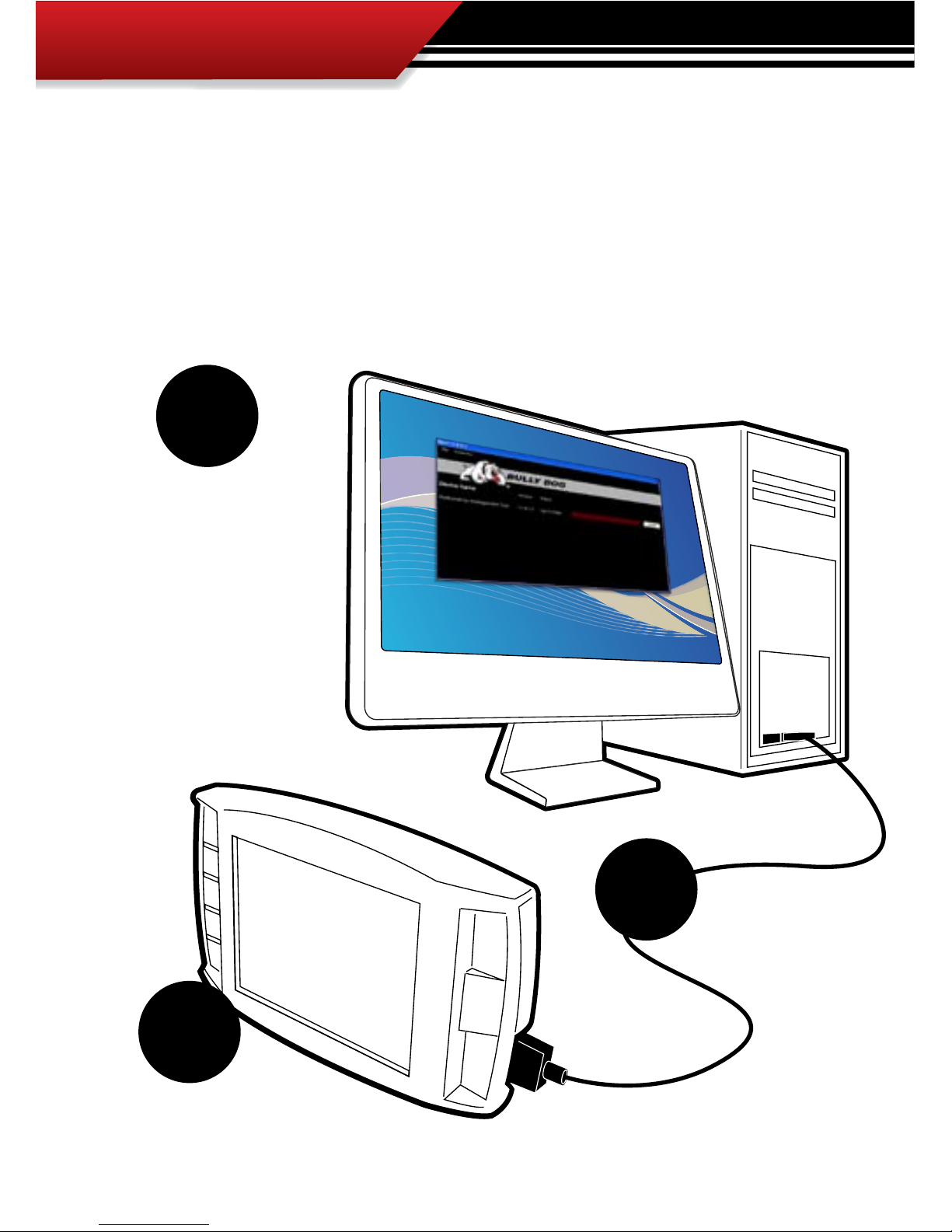
REMEMBER TO UPDATE!!!
Always update the GT before installing on a vehicle using the Update Agent internet
update software. Visit www.bullydog.com to download the Update Agent and get installation instructions for the Update Agent. The diagram below shows just how easy
it is to update any of our electronic products. For detailed update instructions check the
operating instructions.
Use the Update Agent to
update the GT software
before installation on
vehicle. This will ensure
that the GT has the latest programming available from Bully Dog.
Plug in the GT to the
USB Cable. SD card must be
installed in the GT.
Plug the USB cable
into a PC that has
the Bully Dog Internet
Update software: The
Update Agent.
1.
2.
3.

INSTALLATION
3
INTRODUCTION
Congratulations on the purchasing of the GT. The GT is one of the most technologically
advanced tuning and monitoring devices available in the market place, second only to our
Performance Management Tool (GT). The GT includes our Patent pending feature called the
Driving coach which assist users in maximizing driving eciency. Using the driving coach
feature end users can see improvements in fuel economy that will save enough money on
their monthly bill to completely oset the cost of the GT itself.
This product is a relatively easy product to install, if installation assistance is required this product can be installed by any Bully Dog dealer and can also be installed using the assistance of
our technical support team.
At any time during installation and for operating or updating questions please call our technical support line: (866)-285-5936.
For other information visit our web site: www.bullydog.com
This instruction set outlines how to install and operate the GT gauge Tuner.

INSTALLATION
4
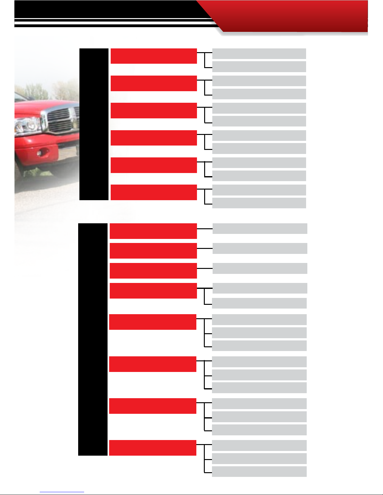
DODGE
5.9L Cummins ‘03-’07 2500
5.9L Cummins ‘03-’07 3500
6.7L Cummins ‘07-’09 2500
6.7L Cummins ‘07-’09 3500
6.7L Cummins ‘07-’09 4500
6.7L Cummins ‘07-’09 5500
RAM
DIESEL applications
INSTALLATION
5
CHEVROLET/GMC
6.6L Duramax ’06-’09 2500
6.6L Duramax ’06-’09 3500
EXPRESS
6.6L Duramax ’06-’09 2500
6.6L Duramax ’06-’09 3500
SAVANNAH
6.6L Duramax ’01-’09 2500
6.6L Duramax ’01-’09 3500
SILVERADO
6.6L Duramax ’01-’09 2500
6.6L Duramax ’01-’09 3500
SIERRA
6.6L Duramax ’06-’09 4500
6.6L Duramax ’06-’09 5500
KODIAK
6.6L Duramax ’06-’09 4500
6.6L Duramax ’06-’09 5500
TOPKICK
FORD
6.0L Power Stroke ’03-’07
6.4L Power Stroke ’08-’09
7.3L Power Stroke ’99-’03
7.3L Power Stroke ’99-’03
7.3L Power Stroke ’99-’03
7.3L Power Stroke ’99-’03
7.3L Power Stroke ’99-’03
F250
6.0L Power Stroke ’03-’07
6.4L Power Stroke ’08-’09
F350
6.0L Power Stroke ’03-’07
6.4L Power Stroke ’08-’09
F450
6.0L Power Stroke ’03-’07
6.4L Power Stroke ’08-’09
F550
6.0L Power Stroke ’03-’07
E250
6.0L Power Stroke ’03-’09
E350
6.0L Power Stroke ’03-’09
E450
6.0L Power Stroke ’03-’06
EXCURSION
Coming Soon
Coming Soon
Coming Soon
Coming Soon
Coming Soon

INSTALLATION
6
CHEVROLET/GMC/CADILLAC
EXPRESS /SAVANNAH
5.3L V8 ‘03-’09 1500
5.3L V8 ‘03-’05 2500
6.0L V8 ‘03-’04 1500
6.0L V8 ‘03-’08 2500
6.0L V8 ‘03-’08 3500
8.1L V8 ‘01-’03 3500
4.8L V8 ‘03-’09 2500
4.8L V8 ‘04-’09 3500
TAHOE
5.3L V8 ‘00-’09
4.8L V8 ‘00-’09
SIERRA/SILVERADO
5.3L V8 ‘99-’09 1500
8.1L V8 ‘01 1500
4.8L V8 ‘99-’09 1500
6.0L V8 ‘02-’07 Denali
6.0L V8 ‘07-’08 Vortec
6.0L V8 ‘99-’08 2500
6.2L V8 ‘07-’09 Denali
6.0L V8 ‘01-’07 Classic
5.3L V8 ‘99-’00 2500
8.1L V8 ‘01-’07 2500
YUKON/SUBURBAN
5.3L V8 ‘00-’09
5.3L V8 ‘00-’09 XL
4.8L V8 ‘00-’09
6.2L V8 ‘07-’09 Denali XL
6.2L V8 ‘01-’06 XL
6.0L V8 ‘01-’06 Denali
6.0L V8 ‘00-’08 Suburban
6.0L V8 ‘01-’06 Denali XL
6.2L V8 ‘07-’09 Denali
6.0L V8 ‘01-’06 XL
8.1L V8 ‘01-’06 Suburban
ESCALADE
5.3L V8 ‘02-’05
6.0L V8 ‘02-’06
6.2L V8 ‘07-’09
AVALANCHE
5.3L V8 ‘02-’09
6.0L V8 ‘07-’08
8.1L V8 ‘02-’06
GAS applications

INSTALLATION
7
5.7L V8 Hemi‘03-’08 1500
5.7L V8 Hemi‘03-’08 2500
5.7L V8 Hemi‘03-’08 3500
DODGE
RAM
FORD/LINCOLN
F150 / E150
4.6L V8 ‘04-’08
5.4L V8 ‘04-’08
F250 / E250
4.6L V8 ‘04-’05
5.4L V8 ‘04-’08
6.8L V10 ‘04-’08
F350 / E350
5.4L V8 ‘04-’08
6.8L V10 ‘04-’08
MOTORHOME
5.4L V8 ‘04
6.8L V10 ‘04-’08
EXCURSION
5.4L V8 ‘04-’05
6.8L V10 ‘04-’05
EXPEDITION
4.6L V8 ‘04-’05
5.4L V8‘05-’07
EXPLORER
4.6L V8 ‘07
5.4L V8‘05-’07
MARK LT
5.4L V8‘05-’07
MUSTANG
4.0L V6 ‘07-’08
4.6L V8 ‘05-’08
6.8L V10 ‘04-’08
F450 / E450
F550 / E550
6.8L V10 ‘04-’08
NISSAN/INFINITY
TITAN
5.6L V8‘05-’09
ARMADA
QX56
PATHFINDER
FRONTIER
PATHFINDER
5.6L V8‘05-’09
5.6L V8‘05-’09
5.6L V8‘08-’09
4.0L V6‘05-’09
4.0L V6‘05-’09
4.0L V6‘05-’09

INSTALLATION
8
PART 1
Physical Installation
These operating instructions are split into four sections:
SECTION 1: Parts Included
SECTION 2: Parts Description
SECTION 3: Installation Overview
SECTION 4: Installation
SECTION 5: Mounting the GT using the Windshield mount

INSTALLATION
9
PART 1 PHYSICAL INSTALLATION CONTENTS
ONLINE UPDATES .............................................................................................. PG.2
INTRODUCTION ............................................................................................... PG. 3
GT DIESEL APPLICATIONS .............................................................................PGS. 45
GT GAS APPLICATIONS..................................................................................PGS. 67
TABLE OF CONTENTS ........................................................................................ PG. 9
BILL OF MATERIALS ........................................................................................PG. 10
PARTS DESCRIPTION ................................................................................PGS. 1114
GT Head Unit .................................................................................................pg. 11
OBD II Adapter Plug .....................................................................................pg. 512
GT Main Wire Harness .................................................................................... pg.13
Power Wire ...................................................................................................pg. 13
Micro SD Card ................................................................................................pg. 14
Universal Windshield Mount ..........................................................................pg. 14
INSTALLATION ......................................................................................... PGS. 1520
Installation Overview ....................................................................................pg. 15
Installation ..................................................................................................pg. 16
Step 1: Connecting the OBDII ........................................................................pg. 16
Step 2: Connecting the Power Wire ..............................................................pg. 17
Step 3: Running GT Main Wire Harness .........................................................pg. 19
Mounting GT to Windshield Mount ................................................................pg. 20
INSTALLATION
10
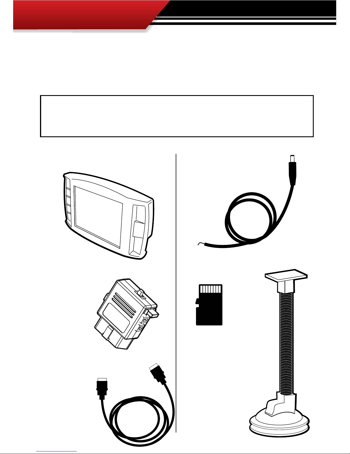
SECTION 1: Parts Included
The list below includes by name the major parts included in your GT package. The tools list
indicates all of the tools necessary to complete the GT install.
1. The GT/Watch Dog Head Unit
3. Main Wire Harness
5. Micro SD Card
3. Windshield Mount
4. The GT/Watch Power Wire
2. OBDII Adapter Plug
TOOLS NEEDED
• Fuse Puller
• Voltage Meter (optional)
EXTRA PARTS (optional)
• Fuse Jack
• Spade connector
INSTALLATION
11
SECTION 2: Parts Description
This section describes each of the parts in the Parts List, each description provides a physical
set of attributes and a purpose for each part. The parts descriptions also list everything that is
included in each assembly.
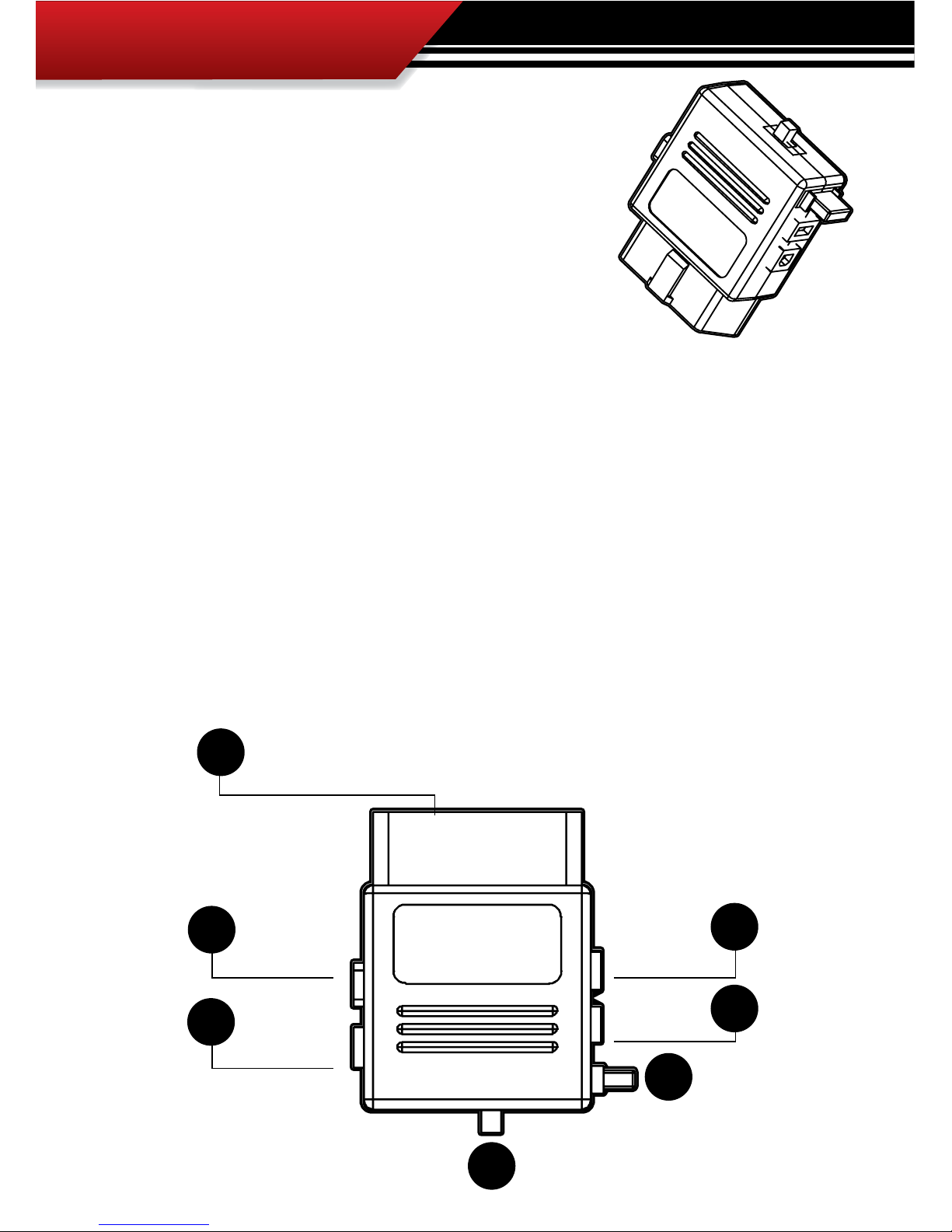
THE GAUGE TUNER:
The main component is the GT Head Unit. The Head Unit is the interface through which all operating functions take place including: Downloading, Monitoring, and the Driving Coach feature.
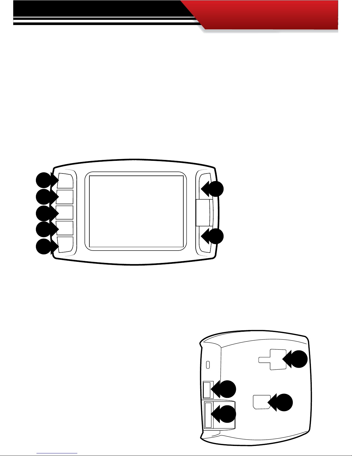
GT Front Side:
The GT has seven capacitive
touch buttons. Capacitive
touch buttons are a button
style that is sensitive to the
presence of your nger. Capacitive buttons do not need
to be pushed, only touched to
activate. The GT interface features a 2.4” LCD screen.
1
2
4
3
GT Parts Back side:
1. T-slot Mount Socket, this will work with a large
range of o the shelve mounting options.
2. Main harness port, electronic port for the main
harness.
3. Micro SD Card Slot
4. Mini USB port
INSTALLATION
12
OBDII ADAPTER PLUG
The OBDII Adapter is a communication hub for the GT. The OBD
ll Adaptor plugs directly into the vehicle OBD ll port. Notice the
OBD ll Adaptor has many ports to support various other functions of the GT. The diagram below illustrates all of the OBDII
parts and ports.
1
5
6
7
2
3
4
1. OBD ll Male End: this is the part of the adapter plug that plugs into the vehicle OBDll port.
2. Main Harness port: the main harness will plug into the GT and into this port during installation.
3. Power wire port: the power wire will run from this port to the vehicle fuse pox during instal-
lation. Plug into the GT and into this port during installation.
4. Power Supply Switch: use this switch to change power from running o of the Power Wire
to OBD ll power as a power supply for the GT.
5. Four Pin USB: This port is used if a Bully Dog pyrometer kit is purchased for the GT.
6. Five Pin USB
7. Adapter Plug Fuse
INSTALLATION
13
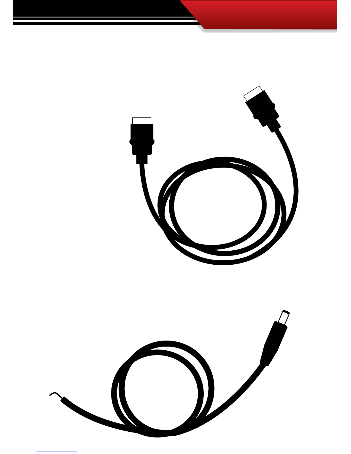
GT MAIN WIRE HARNESS
The main harness connects the GT to the OBD ll Adapter Plug and acts as the main line of communication for the GT.
POWER WIRE
The Power wire connects the OBD ll Adaptor Plug to the vehicle fuse box to
supply power to the GT.
INSTALLATION
14
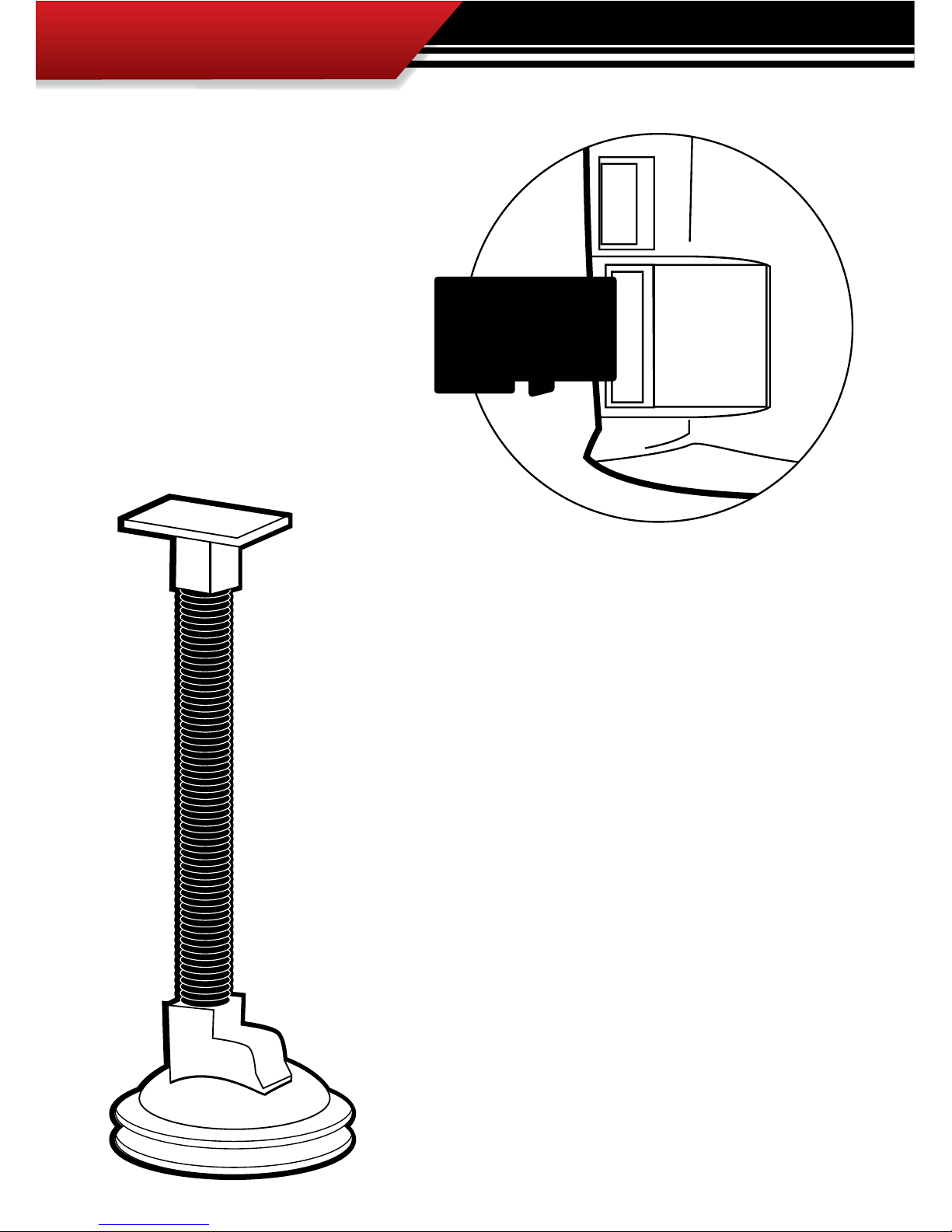
MICRO SD CARD
The Micro SD Card holds all of the electronic les necessary to properly start up
the GT, the SD card must be installed into
the micro SD card slot on the side of the
GT at all times.
UNIVERSAL WINDSHIELD MOUNT
This universal windshield mount is used to install the GT rmly onto
the windshield, it is a suction cup mount that will work on any vehicle
windshield. Check our web site for other mounting options, the GT is
adaptable to a range of other mounting styles.
INSTALLATION
15
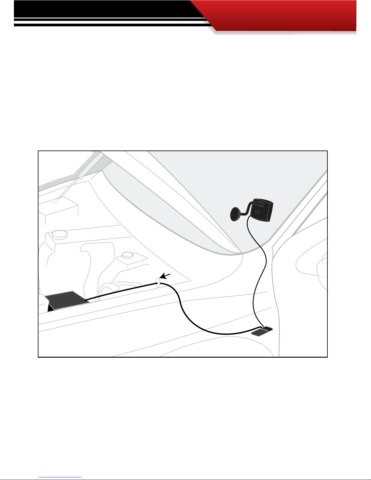
GT & Windshield Mount
OBDII Adapter Plug
OBDII Port
Power Cable
Fuse Box
Fire wall grommet
SECTION 3: Installation Overview
The installation overview illustrates a properly installed GT. This overview is meant to help reference the general location of installed parts and pieces of the GT. Note that some fuse boxes will
be located inside the cab of the vehicle and will not require that the power wire go through the
vehicle re wall.

INSTALLATION
16
SECTION 4: Installation
These installation instructions are split into ve Easy Steps. Follow the steps for the easiest installation of this product.
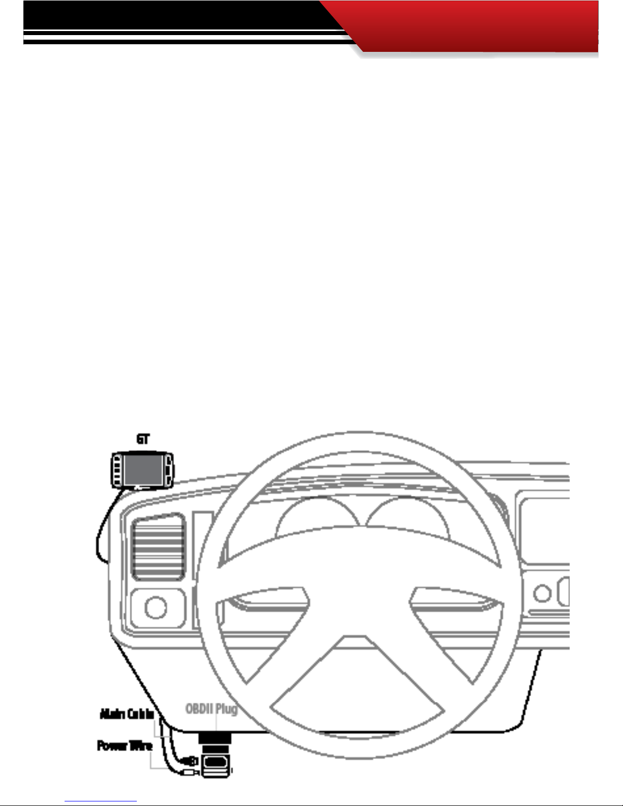
STEP 1: CONNECT THE OBD ll ADAPTER TO THE VEHICLE OBD ll PORT
This step involves locating the vehicle’s OBD ll port and then simply plugging the OBD ll Adapter
Plug into the OBD ll port.
1. As the illustration below shows, OBD ll ports are always located somewhere under the drivers
side dash. The OBD ll port is a male receiver that will have the same shape as the end of the
OBD ll Adaptor plug.
2. Once the OBD ll port is located, then simply plug the OBD ll Adaptor plug into the OBD ll port.
Possible OBDII Port Locations
(location may vary)
INSTALLATION
17
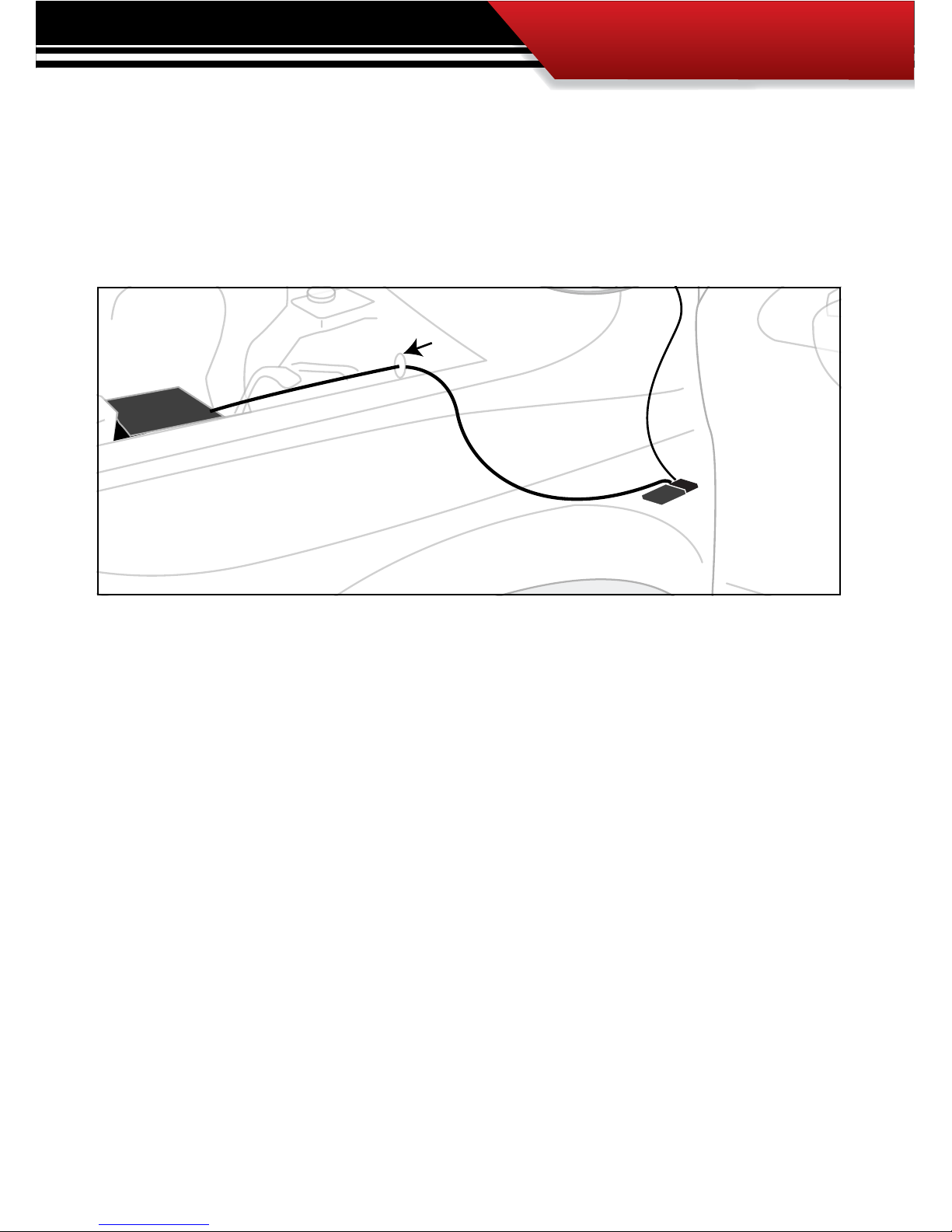
STEP 2: CONNECT THE POWER WIRE TO THE VEHICLE FUSE BOX
Step two involves locating the correct fuse within the vehicle fuse box, and connecting the power
wire from the OBD ll Adaptor plug to the fuse in the fuse box.
IDENTIFY THE CORRECT FUSE:
1. Locate the vehicle fuse box; the vehicle owners manual will indicate where the fuse box is located
within the vehicle.
2. Open the fuse box and identify a fuse that has “key on power.” To identify the correct fuse, nd an
accessory fuse using the fuse diagram in the vehicle owners manual. If the vehicle manual does not
help identify an accessory fuse use a voltage meter to identify a fuse that supplies power only when
the key is in the on position.
CONNECT THE POWER WIRE FROM THE OBD II BLOCK TO THE CORRECT VEHICLE FUSE:
1. Connect the power wire to the power wire port on the OBD ll Adaptor plug.
2. Run the raw end of the power wire to the vehicle fuse box, in many cases this will mean taking the
power wire through the vehicle re wall. On most vehicles the power wire can run through an existing port, it is not necessary to drill.
3. Remove the correct fuse from the fuse box and plug the fuse back into its original location along
with the power wire. For a the cleanest install see our clean install instructions on the next page.
GT & Windshield Mount
OBDII Adapter Plug
OBDII Port
Power Cable
Fuse Box
Fire wall grommet

18
INSTALLATION
FOR A CLEAN INSTALL INTO THE FUSE LOCATIONS:
There are multiple dierent fuse types in OEM vehicles. For a clean install, use a fuse tap and
spade connector that will work with the specic fuse being used for this install.
1. Once the end of the power wire is near the fuse box, prepare the end of the power wire by attaching
a spade connector to the end of the wire.
2. Remove the correct fuse from its location and then replace that fuse with a fuse tap that is made
for that size of fuse.
3. Connect the spade connect to the end of the fuse tap.
4. Use zip ties to secure any loose wire left hanging from excess slack in the power wire.
INSTALLATION
19
STEP 3: RUN GT MAIN WIRE HARNESS
In this section you will connect the GT Main Harness to the OBD ll Adaptor plug and then run the
other end of the main harness up the side of the vehicle dash and connect it to the back of the GT.
1. Plug one end of the Main Harness into the Main Harness port on the OBD ll adapter plug.
2. Run the other end of the harness up through the vehicle dash on the driver’s side so that the end of the
harness emerges from the dash near the vehicle A-pillar. It may be necessary to temporarily remove
the vehicle weather stripping and dash panel to achieve an installation where the Main Harness cannot be seen.
3. Plug the Main Harness into the back side of the GT, make sure that there is enough slack in the main
harness to accommodate mounting the GT to the windshield.
INSTALLATION
20
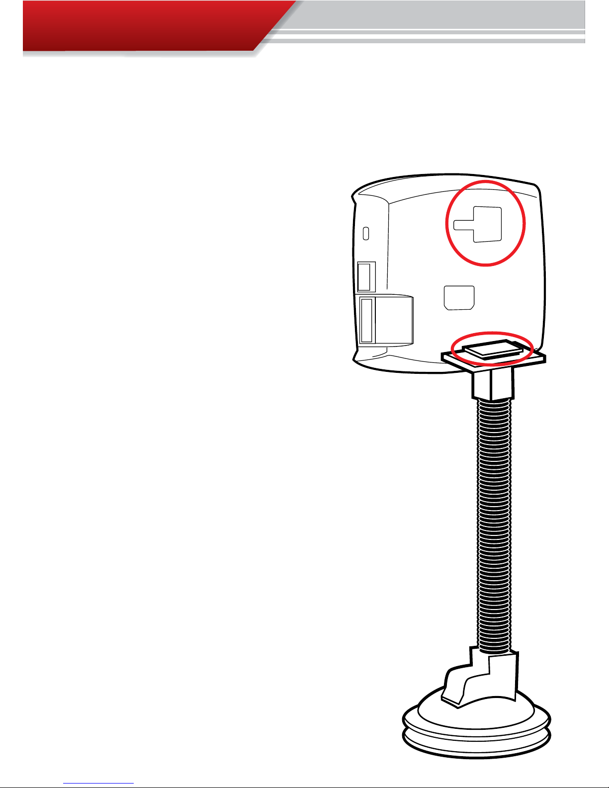
SECTION 5: Mounting the GT using the Windshield mount
The final step to installation is mounting the GT to the windshield using the universal windshield mount.
1. Locate the T-shaped mount socket on the back
side of the GT.
2. Notice that the top of the universal mount will t
into T-shaped socket and slide forward to secure
the GT to the mount.
3. With the GT connected to the mount use the
windshield mount to secure the GT to the windshield. Be sure that the position of the GT does
not obstruct the view of the road or distract the
driver from their primary responsibility, which is
driving responsible.
INSTALLATION

OPERATION
21
PART 2
Operating Instructions
These operating instructions are split into four sections:
SECTION 1: Button Navigation
SECTION 2: Set up Wizard for installing download
SECTION 3: Exploring the General Display
SECTION 4: The Driving Coach
SECTION 5: Main Menu and Sub Menus

OPERATION
22
OPERATING INSTRUCTIONS ................................PGS. 2844
SECTION 1: Button Navigation ................................................pg. 23
SECTION 2: GT Setup Wizard for Installing Download ........ pgs. 24-26
Step 1: The Setup Wizard .................................................................................. 24
Step 2: Vehicle Selection ................................................................................... 25
Step 3: The Download ....................................................................................... 34
SECTION 3: Exploring the Menu System ........................... pgs. 27-29
Five Button Functions of the Main Screen .................................................. pg. 28
Large Gauge Styles/The Driving Coach ......................................................pg. 29
SECTION 4: The Driving Coach .......................................... pgs. 30-31
Driving Coach Setup Wizard ........................................................................pg. 30
Driving Coach Display ................................................................................. pg. 31
SECTION 5: Main Menu & Sub-menus ............................... pgs. 32-52
Change Vehicle ............................................................................................pg. 33
Install download .........................................................................................pg. 34
Gauge Setup ................................................................................................pg. 47
Driving Coach Setup Wizard ........................................................................pg. 49
User options ................................................................................................pg. 53
Vehicle Options ...........................................................................................pg. 57
OPERATION
23
®
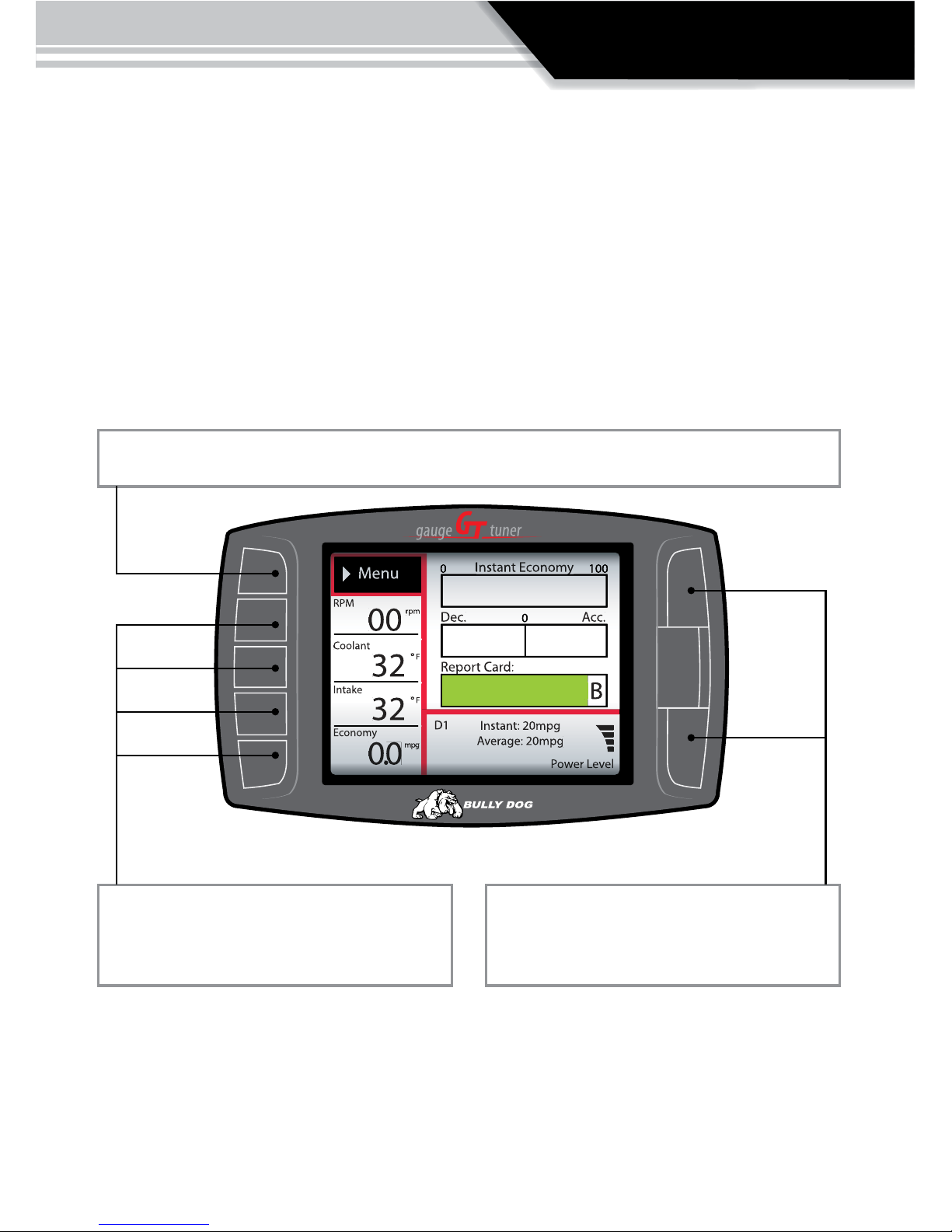
SECTION 1: Button Navigation
Capacitive Touch Buttons: The buttons used on the GT are Capacitive touch. Capacitive touch buttons only require a touch on the button area rather than a push like
regular buttons require. It is not necessary to apply any significant force to the button while navigating through product screens.
Press the top left button to enter the Main Menu, also use this button to exit menus.
Press any of the four buttons on the left to
select items on the screen that are adjacent to
the button position.
In general these buttons work as up and down
buttons, they may also be used to select items
on the screen adjacent to these buttons.
OPERATION
24
SECTION 2: Set up Wizard for installing download
The Setup Wizard is a step by step process through the vehicle selection process and
download process. The Setup Wizard appears on the screen automatically and will
only appear the very first time the GT is installed. Opting out of the Setup Wizard
is OK, the vehicle selection process and download process can also be performed
through the main menu.
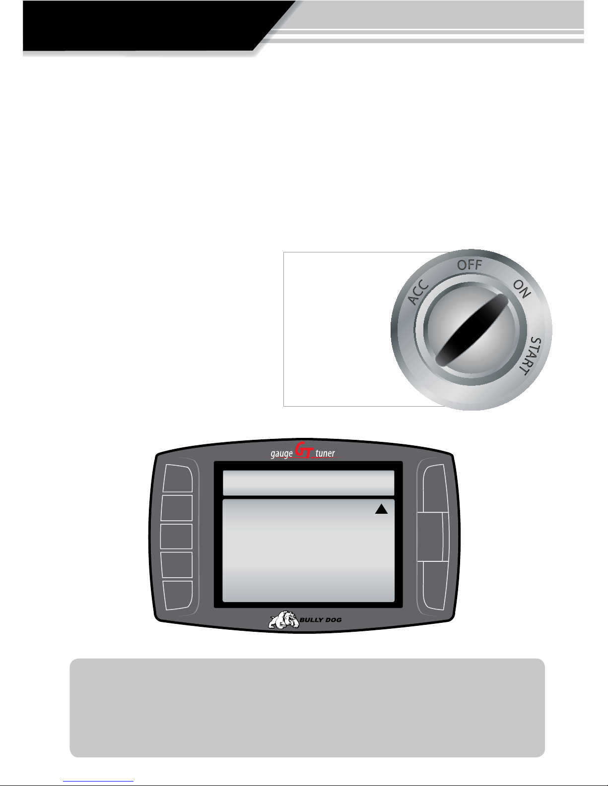
STEP 1: THE SETUP WIZARD:
1. Once physical installation is complete
insert the key into the vehicle ignition
and turn it to the on/run position.
2. The GT screen will now light up and
the Setup Wizard will appear on the
screen.
Turn key to the “ON” position
when the Tuner
calls for it.
Do not start
the engine unless
the instructions or the
tuner specically
calls for it.
®
WELCOME
Welco me t o the GT Wizard.
Th e ne xt f ew ste ps will t ake you
throu gh the in it ial se tu p and
downl oa d proc es s .
(
Pres s MOR E to co nt inu e to th e ne x t s cre en )
MORE
TROUBLE SHOOTING: If the Setup Wizard does not appear automatically and the GT displays
the Main Screen then the vehicle selection process and download process will have to be
performed through the main menu. From the main screen enter the main menu and navigate
to the Change Vehicle screen. Once the correct vehicle is selected, enter the download menu
from the main menu.
OPERATION
25
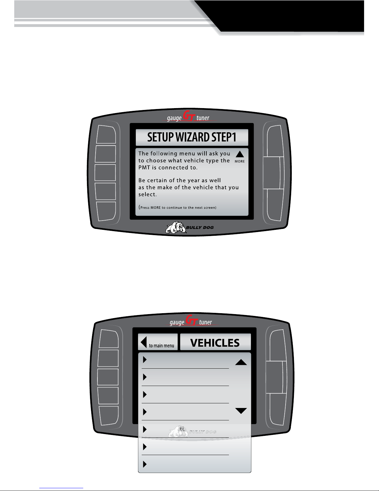
STEP 2: VEHICLE SELECTION
Select the option from the vehicle selection screen that most matches the vehicle in use; the GT will
not be able to perform a download or monitor correctly if the correct vehicle type is not specied.
The list of vehicles in the illustration below demonstrate the vehicle selection list for the Diesel
version of the GT; the Gasoline version will have a completely dierent list.
‘03-’07 Ford 6.0L Power Stroke
‘08 Ford 6.4L Power Stroke
‘06-’07 Dodge 5.9L Cummins
‘08 Dodge 6.7L Cummin
‘01-’05 GM 6.6L Duramax
‘06-’07 GM 6.6L Duramax
‘08 GM 6.6L Duramax
Go Back
OPERATION
26
®
INSTALL DOWNLOAD?
YES
NO
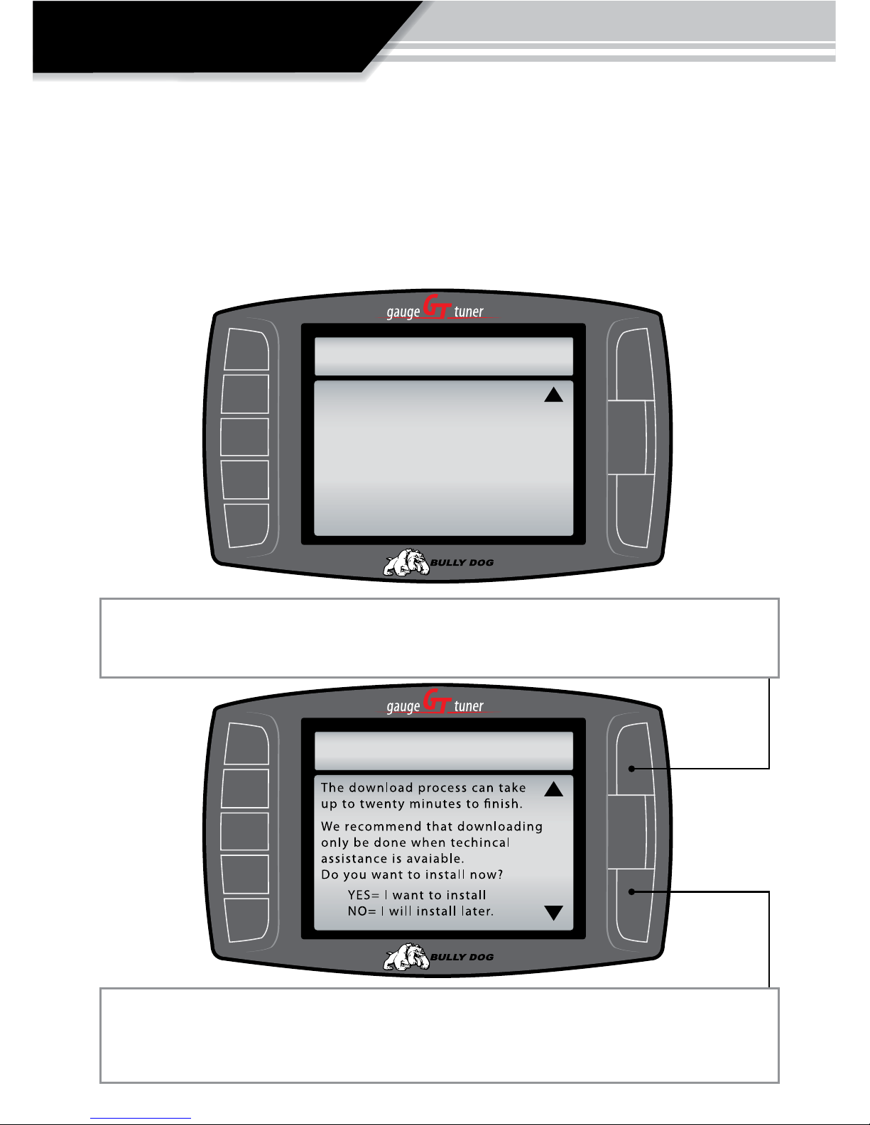
STEP 3 THE DOWNLOAD:
In Step 2, select whether to install a performance download now or later. The setup wizard
will initiate the download. For details on the download process see the Install download section on page 34. It is OK to opt out of the Download at this point in the setup wizard. It is very
easy to load and unload the download from the main menu.
Opt in: To complete the download in the setup wizard process simply press the up arrow button to select
“Yes.” Then simply follow the on screen instructions to complete a download.
Opt out: If you choose to not download at this time you will still have monitoring capabilities even though
no download has been entered into the vehicle. To download at a later time see the Install Download
instructions when ready.
®
SETUP WIZARD STEP2
Do you want to download?
You can either install a download
now or install later from the main
menu.
Your GT will only be able to run
monitoring features until the
download is completed.
(Press MORE to continue to the next screen)
MORE
 Loading...