

Page 1

1
BÜCHI Vac V-500/V-501/V-502/V-503 Table of Contents
Table of Contents
en, Version I (32 pages) Order No.
V-500 Operating Instructions 96696
1 Scope of Delivery 2
1.1 Büchi Vac V-500 2
1.2 Büchi Vac V-501 3
1.3 Büchi Vac V-502 4
1.4 Büchi Vac V-503 5
2 Safety 6
3 Function 9
3.1 Büchi Vac V-500 9
3.2 Büchi Vac V-501 10
3.3 Büchi Vac V-502 11
3.4 Büchi Vac V-503 12
4 Putting into Operation 14
4.3 Büchi Vac V-500 15
4.4 Büchi Vac V-501 15
4.5 Büchi Vac V-502 16
4.6 Büchi Vac V-503 17
4.7 V-500 with more Vacuum Controllers V-800 18
5 Operation 19
6 Maintenance 22
7 Putting out of Operation 28
8 Spare Parts 29
9 Appendix 31
Please read these operating instructions carefully before using
the BÜCHI Vac V-500/501/502/503
..
..
. Keep these
instructions in the proximity of the device so that you can
consult them immediately whenever necessary.
Chapter 2 contains important safety instructions. Read them
carefully; they are essential for the safe operation of the
device.
Technical changes may be made without prior notice. These
operating instructions may not, either wholly or in part, be reproduced or rewritten by the use of electronic or optical systems,
copied, or distributed without the express written permission of
the firm BÜCHI Labortechnik AG. All rights reserved.
Copyright © BÜCHI Labortechnik AG 1998, 1999, 2000
Page 2
2
1 Scope of Delivery
1 Scope of Delivery BÜCHI Vac V-500/V-501/V-502/V-503
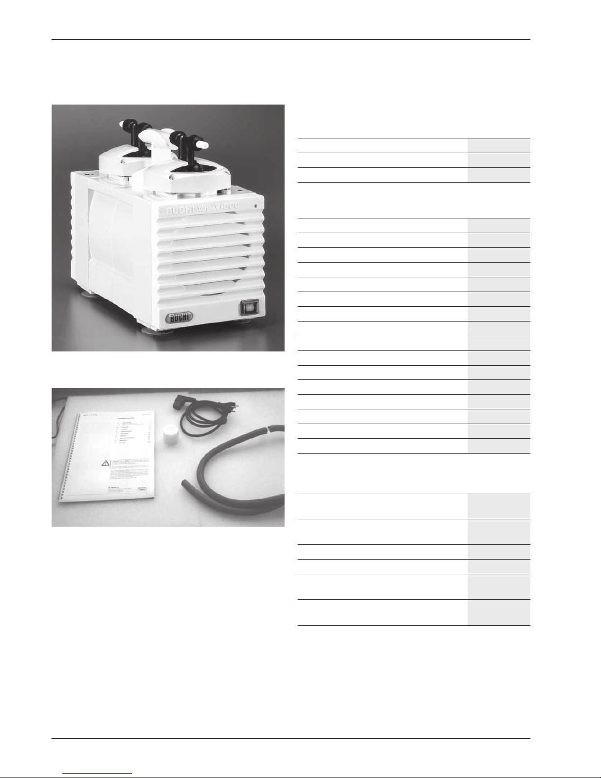
Fig 1: Vac V-500
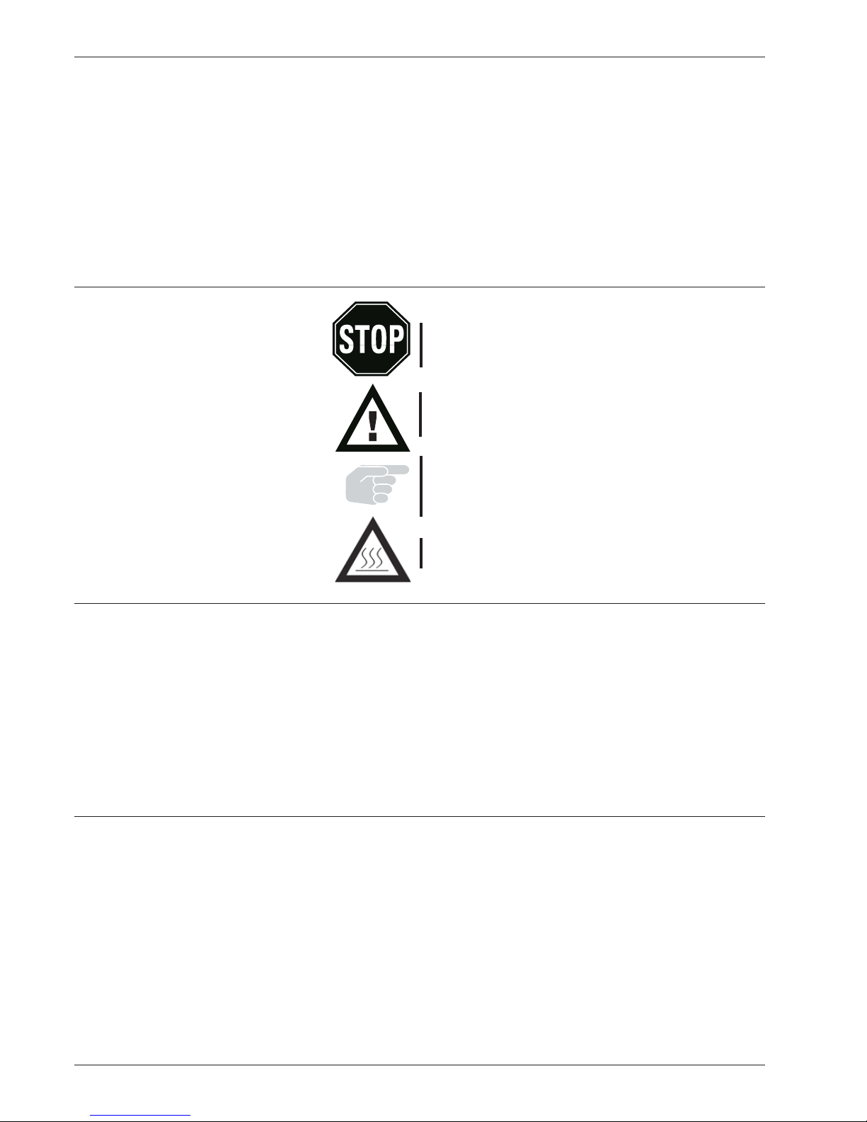
Fig 2: Enclosed parts Büchi Vac V-500
1.1 Büchi Vac V-500
Description Order No.
Büchi Vac V-500 230 V 50 Hz 37340
Büchi Vac V-500 120 V 50/60 Hz 37339
Büchi Vac V-500 100 V 50/60 Hz 38050
Enclosed parts
1 Sound absorber 37947
2 m Vacuum hose 17622
1 Power cable PNE, 1.5m
Type CH 10010
Type Schuko 10016
Type GB 17835
Type USA 10020
Type AUS 17836
1 Operating instructions:
German 96695
English 96696
French 96697
Italian 96698
Spanish 96699
1 Hose connection GL-14 straight
1 Hose connection GL-14 bent
Table 1: Enclosed parts Büchi Vac V-500
Optional accessories
1 Stand with holder for valve unit, 38021
secondary condenser
1 Secondary condenser complete 38022
with collecting tank
1 Vacuum Controller V-800 230 V 40736
1 Vacuum Controller V-800 120 V 40737
1 Spare parts set consisting of 38120
2 diaphragms, 2 valve heads complete
1 Connecting cable 38010
Vacuum controller to the pump
Table 2: Optinal accessories for Büchi Vac V-500
Page 3

3
BÜCHI Vac V-500/V-501/V-502/V-503 1 Scope of Delivery
Fig 3: Vac V-501 with secondary condenser
Fig 4: Enclosed parts Büchi Vac V-501 with secondary condenser
1.2 Büchi Vac V-501 with secondary condenser
Description Order No.
Büchi Vac V-501 with 38001
secondary condenser 230 V 50 Hz
Büchi Vac V-501 with 38006
secondary condenser 120 V 50/60 Hz
Büchi Vac V-501 with 38051
secondary condenser 100 V 50/60 Hz
Enclosed parts
1 Secondary condenser 37775
1 Collecting tank for 37949
secondary condenser
1 Gasket for secondary condenser 37873
1 Holder for secondary condenser 38086
and collecting tank
1 Stand with holder for 38021
secondary condenser
2 m Vacuum hose 17622
1 Power cable PNE, 1.5 m
(see 1.1 for article number)
1 Operating instructions
(see 1.1 for article number)
1 Hose connection GL-14 straight
1 Hose connection GL-14 bent
1 Spring lock washer 37872
1 Silicone hose 04133
Table 3: Enclosed parts Büchi Vac V-501 with secondary condenser
Optional accessories
1 Vacuum Controller V-800 230 V 40736
1 Vacuum Controller V-800 120 V 40737
1 Valve unit compl. 37968
1 Cooling water valve 31356
1 Control cable for R-134/R-144 31466
to V-500
1 Special cable for KNF controller 38015
1 Special cable for Vacuubrand 38014
1 Thermostatic jacket for 37616
secondary condenser
1 Spare parts set consisting of 2 dia- 38120
phragms, 2 valve heads complete
1 Connecting cable 38010
Vacuum controller to the pump
Table 4: Optional Accessories Büchi Vac V-501 with add. condenser
Page 4

4
1 Scope of Delivery BÜCHI Vac V-500/V-501/V-502/V-503
Fig 5: Vac V-502 with Vacuum Controller
1.3 Büchi Vac V-502 with Vacuum Controller
V-800
Description Order No.
Büchi Vac V-502 with Vacuum 38650
Controller V-800 230 V 50 Hz
Büchi Vac V-502 with Vacuum 38652
Controller V-800 120 V 50/60 Hz
Büchi Vac V-502 with Vacuum 38653
Controller V-800 100 V 50/60 Hz
Enclosed parts
1 Sound absorber 37947
1 Vacuum Controller V-800 230 V 40736
Vacuum Controller V-800 120 V 40737
1 Stand with holder for valve unit, 38021
secondary condenser
1 Valve unit, complete 37968
1 Connecting cable 38010
Vacuum controller to the pump
2 m Vacuum hose 17622
1 Power cable PNE 1.5m
(see 1.1 for article number)
1 Operating instructions:
(see 1.1 for article number)
1 Hose connection GL-14 straight
1 Hose connection GL-14 bent
Table 5: Enclosed parts Vac V-502 with Vacuum Controller
Optional accessories
1 Secondary condenser complete 38022
with collecting tank
1 Cooling water valve 31356
1 Spare parts set consisting of 2 38120
diaphragms, 2 valve heads complete
Table 6: Optional Accessories Vac V-502 mit Vacuum Controller
Page 5

5
BÜCHI Vac V-500/V-501/V-502/V-503 1 Scope of Delivery
Fig 6: Vac V-503 with Vacuum Controller and secondary condenser
Fig 7: Enclosed parts Vac V-503 with Vacuum Controller and
secondary condenser
1.4 Büchi Vac V-503 with secondary condenser
and Vacuum Controller V-800
Description Order No.
Büchi Vac V-503 with Vacuum 38654
Controller V-800 230 V 50 Hz
Büchi Vac V-503 with Vacuum 38656
Controller V-800 120 V 50/60 Hz
Büchi Vac V-503 with Vacuum 38657
Controller V-800 100 V 50/60 Hz
Enclosed parts
1 Vacuum Controller V-800 40736
1 Vacuum Controller V-800 40737
1 Connecting cable 38010
Vacuum controller to the pump
1 Valve unit, complete 37968
1 Secondary condenser 37775
1 Collecting tank for 38949
Secondary condenser
1 Gasket for secondary condenser 37873
1 Holder for secondary condenser 38086
and collecting tank
1 Stand with holder for valve unit, 38021
secondary condenser
2 mVacuum hose 17622
1 Power cable PNE 1.5m
(see 1.1 for article number)
1 Operating instructions
(see 1.1 for article number)
1 Hose connection GL-14 straight
1 Hose connection GL-14 bent
1 Spring lock washer 37872
3m Silicone hose 04133
Table 7: Enclosed parts Büchi Vac V-503 with vacuum controller and
secondary condenser
Optional accessories
1 Thermostatic jacket for 37616
secondary condenser
1 Cooling water valve 24V AC 31356
1 m Vacuum hose 17622
Table 8: Optional Accessories Büchi Vac V-503 with vacuum controller
and secondary condenser
Page 6
6
2 Safety
2 Safety BÜCHI Vac V-500/V-501/V-502/V-503
The device is built with state-of-the-art technology and according
to recognized safety regulations. Nevertheless, using this device
can lead to certain risks and dangers:
• If the device is not used according to these instructions.
• If the device is used by personnel who have not been properly
trained..
2.1 Symbols
Stop
Information about risks which can lead to extensive property
damage or to serious or life-threatening personal injury.
Warning
Information about risks which can lead to damage to one’s
health or to property damage.
Reference
Information which refers to technical requirements. Failure
to heed these requirements can lead to malfunctions, poor
economic performance, and production losses.
Warning
Surface temperature more than 60°C.
2.2 Requirements for the Operator
The device may be used only by laboratory personnel or other
persons who, due to their training or professional experience,
are capable of recognizing possible dangers which might arise
from the use of the device.
Personnel who do not have this training or who are presently
in training must be given careful and exact instruction. These
operating instructions are intended for use as a basis for such
instruction.
2.3 Proper Use
The device was designed and built for laboratory use. Its proper use is the evacuation of laboratory vacuum devices up to
10 mbar. This is done by means of a PTFE diaphragm pump,
with or without regulation through one or more vacuum
controllers.
Uses:
• Evacuation of distillation apparatus, in particular rotation
evaporators.
• Vacuum filtrations
• Vacuum drying cabinets
• Drying ovens
Page 7

7
BÜCHI Vac V-500/V-501/V-502/V-503 2 Safety
2.4 Safety Features
Two fuses (3.15 AT) have been built into the device to protect
it from a short circuit. The pump motor is protected from
overheating by a temperature governor. The pump is 100%
free of oil. The bearings do not require lubrication. All
bearings are completed sealed and self-lubricating.
2.5 Improper Use
Any use of the device other than those given above or any
use of the device which is not in accordance with the
technical data shall be regarded as a misuse. The operator
bears the sole responsibility for any and all damage which
may result from such misuse. The device is not suitable for
pumping liquids or solid particles. The result of such a use
would be the destruction of the pump or a loss in
performance capability.
In particular, the device must not be used in the following ways:
• Use of the device in rooms which require ex-protected
apparatus.
• Processing of samples which can explode or ignite due to
a blow, friction, heat, or sparks (e.g., explosives, etc.).
• Use of the device for digestions (e.g., Kjeldahl)
• Use of the pump to produce over-pressure
• Operation of the device in a surrounding temperature
of > 40° C.
2.6 General Risks
In general, risks can arise from
• Glass parts which are not suitable for use under vacuum
conditions
• Solvents which can react with one another if they mix in
the pump or in the secondary condenser.
• Ignition sources in the immediate vicinity of the pump/
pump system outlet.
• Flammable gases or solvent vapors in the immediate
vicinity of the device.
• Damaged glass equipment
• Bent hoses on the outlet side
Page 8
8
2 Safety BÜCHI Vac V-500/V-501/V-502/V-503
2.7 Safety Measures
Protective clothing such as goggles and laboratory coats
must be worn during operation of the device.
These operating instructions must be available at all times
to operating personnel at the place of operation of the device
and should be regarded as an integral part of the Büchi
Vac V-500-503. Instructions in other languages, which may
be ordered separately, must also be kept with the device.
Modifications
Modifications of the device or of spare parts or of
accessories as well as the use of spare parts or accessories
other than those mentioned in these operating instructions
is allowed only with the prior written permission of BÜCHI
Labortechnik AG.
Responsibility for the operator
The operator is responsible for the instruction of his
personnel. Copies of these operating instructions in various
languages can be ordered for this purpose.
The operator shall inform the manufacturer without delay of
any safety-related events which might occur during operation
of the device.
Regional and local statutes and regulations must be observed.
It is forbidden for anyone other than authorized maintenance
personnel to remove the front or back plate using standard
tools. Damaged glass equipment may not be used under
vacuum conditions.
Touching any parts of the device carrying electrical current
can result in fatal injury!
Page 9
9
BÜCHI Vac V-500/V-501/V-502/V-503 3 Function
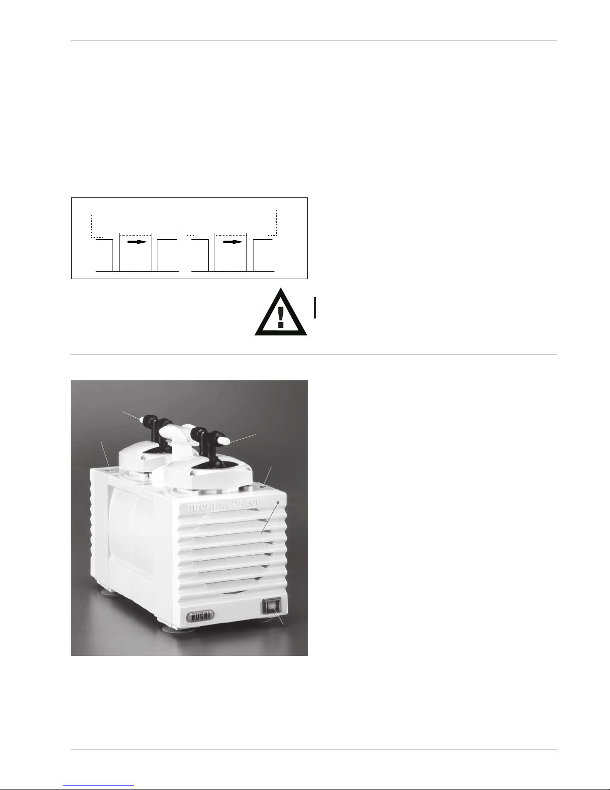
Fig. 9a: Vac V-500 front view
3 Function
The Büchi Vac V-500 is a vacuum pump suitable for evacuating
laboratory equipment to a vacuum of <10 mbar. This is done
with a PTFE diaphragm pump. The pump can be used as an
individual device to create a vacuum and can be expanded to
a complete vacuum system by means of the optional
accessories such as secondary condenser and vacuum
controllers (V-501/502/503).
In the following pages, reference will often be made to pump
inlet and pump outlet.
This distinction is important and can be recognized on the
valve heads as follows. Arrows on both valve heads show the
direction of the gas flow.
The pump inlet , is at the beginning of the arrow, the tip of
the arrow is the pump outlet .
Never turn the valve heads so that the arrows point to one
another!
3.1 Function of the Büchi Vac V-500
PTFE diaphragm pump: vacuum pump suitable for evacuating
laboratory devices <10 mbar.
Main switch
Pump outlet GL-14
Pump inlet GL-14
Rod fastening
Stand rod socket, front
Stand rod socket, rear
Fig. 8: Gas flow: valve heads
Pump inlet
Pump outlet
(Direction main switch)
Page 10
10
3 Function BÜCHI Vac V-500/V-501/V-502/V-503
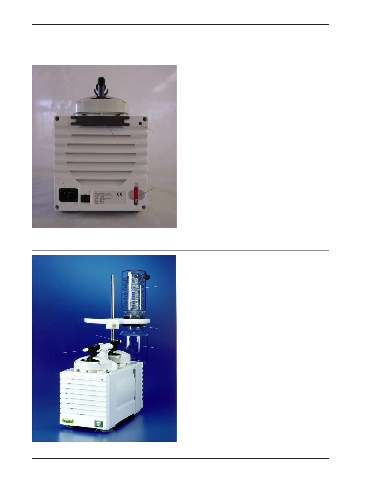
Fig. 10: Vac V 501 with secondary condenser
Fig. 9b: Vac V-500 rear view
Allen wrench
Rod fastening
Connection 24 V ~= Switchbox
Power connection
Installation tool
In case a control cable is connected to the 24V connection
the switchbox switches automatically to external.
The main switch has to be ON (EIN) and can only be
switched ON or OFF via the controller.
3.2 Function of the Büchi Vac V-501
Vacuum system with PTFE diaphragm pump V-500 and
secondary condenser, suitable for evacuating laboratory
equipment to a vacuum of <10 mbar. The secondary
condenser removes any solvent vapors following the pump
(to the physical minimum).
Main switch
Pump outlet
Pump inlet
Secondary condenser
Collecting tank
Supporting ring
Page 11

11
3.3 Function of the Büchi Vac V-502
Vacuum system with PTFE diaphragm pump V-500 and vacuum
controller, suitable for controlled evacuation of laboratory
devices to a vacuum of <10 mbar. This system creates,
regulates, and maintains a vacuum at a constant level by
automatically resuming operation in the event of a vacuum
loss and restoring the vacuum to the set level. To achieve
this, the vacuum pump is turned on and off directly.
The vacuum, selected for the specific solvent, permits almost
100% condensation in the condenser of the distilling device.
This permits a massive reduction of solvent emissions. In
addition, the flow of the cooling water can be controlled during
the distillation process by an optional cooling water valve. 95%
of the cooling water can be saved in this way. The vacuum
controller turns the pump on and off as required by means of
the integrated switchbox.
Main switch
Pump inlet
Sound absorber
Vacuum Controller V-800
Valve unit
Holder
Stand
The sound absorber does not prevent emissions into the
laboratory air. For this reason, the pump must be placed
under a fume hood when the sound absorber is used.
Fig. 11: Vac V-502 with vacuum controller V-800
BÜCHI Vac V-500/V-501/V-502/V-503 3 Function
Page 12

12
Fig. 12: Vac V-503
3 Function BÜCHI Vac V-500/V-501/V-502/V-503
3.4 Function of the Büchi Vac V-503
Vacuum system with PTFE diaphragm pump V-500 and vacuum
controller, suitable for controlled evacuation of laboratory
devices to a vacuum of <10 mbar. This system creates,
regulates, and maintains a vacuum at a constant level by
automatically resuming operation in the event of a vacuum
loss and restoring the vacuum to the set level. To achieve
this, the vacuum pump is turned on and off directly.
The vacuum, selected for the specific solvent, permits almost
100% condensation in the condenser of the distilling device.
This permits a massive reduction of solvent emissions. The
vacuum controller turns the pump on and off as required by
means of the integrated switchbox. The secondary condenser
removes any solvent vapors following the pump. In addition,
the flow of the cooling water can be controlled during the
distillation process by an optional cooling water valve. 95% of
the cooling water can be saved in this way.
Main switch
Pump inlet GL-14
Pump outlet GL-14 – connect to secondary condenser
using vacuum hose (see 3.5)
Secondary condenser
Collecting tank
Vacuum Controller V-800
Valve unit
Holder
Stand
Elastic ring
3.5 Function of the secondary condenser
Cooling water inlet
Cooling water outlet
Intake for exhaust gases from the pump
Outlet for exhaust gases
Assembly:
• Mount gasket in holding ring
• Click holding ring into white holder
• Place the supporting ring on the holding ring and secure
the secondary condenser by pressing down lightly and
turning 60°.
• Mount collecting tank
Fig. 13: Secondary condenser
Page 13

13
BÜCHI Vac V-500/V-501/V-502/V-503 3 Function
3.6 Function of the Vacuum Controllers
See separate operating instructions.
3.7 Function of the valve unit
Hose connection to 1
st
rotation evaporator
Hose connection to 2nd valve unit
Hose connection to vacuum controller
Hose connection to pump inlet (intake end)
Connecting cable to vacuum controller
When the unit is operated with only one rotation evaporator,
the outlet R2 is closed with a cap.
During operation, the valve unit is in a vacuum. Please
examine glass parts for splinters, cracks, stars.
Fig. 14: Valve unit
Page 14

14
4 Putting into operaton BÜCHI Vac V-500/V-501/V-502/V-503
4 Putting into operation
Please check all parts for damage when unpacking. It is
important that any transport damage be discovered when
the parts are unpacked. If necessary, a record of the
condition of the parts should be made immediately (report
to postal service, railway service, or shipping company).
Keep the original packaging for the event of a later transport.
4.1 Placement
The device must be set up on a stable, clean, and level
surface. The surrounding temperature may not exceed 40°
C. Proper air circulation is necessary.
The device must be placed at a minimum of 20 cm from
walls and other objects in order to prevent damage. Containers, chemicals, or other devices may not be placed
behind the pump.
4.2 Connections
4.2.1 Electrical connections
Ensure that the electric current available from the location’s
outlets is the same voltage as that indicated by the label
on the apparatus. The device must always be connected
to a grounded outlet. External couplings and extension cords
must have a protective conductor (3-pin couplings, cables,
or plug and socket connections). There must be no break
in any part of the protective conductor. This will avoid risks
resulting from internal defects.
Connect the pump to the power source with the enclosed
cable.
4.2.2 Other connections
Before putting the device into operation, the screw caps
on the connections must be replaced by GL-14 connections
or sound absorbers.
Please be sure that none of the hoses are bent closed
(bends, the device is resting on the hose).
Replace brittle hoses.
The hoses should be secured with standard hose clamps
or cable binders for safety.
The device must never be put into operation without an
exhaust hose. The exhaust hose must not be pointed
towards hot objects or towards objects which produce
sparks.
The exhaust hose must end in a fume hood so that none of
the vapors from the solvents can be released in the room.
Page 15

15
4.3 Büchi Vac V-500
Sound absorber
Vacuum connection to valve unit
• Screw the sound absorber onto the pump outlet.
• Connect the pump inlet to the rotation evaporator valve
unit using the vacuum hose, as shown in the drawing.
• Connect the power cable.
4.4 Büchi Vac V-501 with secondary condenser
Stand
Holder
Secondary condenser
Collecting tank
Mechanical and electrical connections
• Insert the stand into the desired socket of the pump
and secure it with an allen wrench.
• Secure the white plastic holder to the stand using
an allen wrench.
• Connect the power cable.
Vacuum connections
Connect the pump inlet to the valve unit as shown in the
drawing.
Connect the secondary condenser to the pump outlet.
Secondary condenser
• Secure the secondary condenser and the collecting
tank to the holder. Make sure that the gasket has
been placed between the two glass parts.
• Connect the secondary condenser to the condenser of
the Rotavapor with hoses. The cooling water should flow
first through the secondary condenser, then through the
Rotavapor’s condenser.
• Connect an exhaust hose to the outlet of the secondary
condenser . This hose should run into a fume hood.
Fig. 16: VAC V-501 with secondary condenser
BÜCHI Vac V-500/V-501/V-502/V-503
4 Putting into operaton
Fig. 15: V-500 connection to Rotavapor
Fig. 17: V-501 with secondary condenser connection to Rotavapor
Page 16

16
Fig. 19: Installation Vac V-502 with V-800 with Rotavapor
4 Putting into operation BÜCHI Vac V-500/V-501/V-502/V-503
4.5 Büchi Vac V-502
Stand
Valve unit
Holder
Vacuum Controller V-800
Sound absorber
Mechanical and electrical connections
• Screw sound absorber onto pump outlet
• Insert the stand into the desired socket on the pump
and secure it.
• Secure the white plastic holder to the stand .
• Fasten the vacuum controller V-800 to the stand .
• Insert the valve unit into the holder .
• Attach the cable from the valve unit to the vacuum
controller connection „V“ (Connection A).
• Join the connection Pump of the vacuum controller to the
24 V ~= on the V-500 with the control cable (Connection B).
• Connect the power cable.
Vacuum connections
The following vacuum connections are made using the
vacuum hose:
Pump inlet to the valve unit (via the connection “Pump”).
• Rotation evaporator to the valve unit
(via the connection “R1”).
• Vacuum controller V-800 to the valve unit
(via the connection “V.Contr.”).
• Fit sealing cap on connection R2.
The pump will now be turned on and off by the V-800.
Fig. 18: VAC-502
B
Pump
V. Contr.
R1
R2
A
Page 17

17
4.6 Büchi Vac V-503
Stand
Valve unit
Holder
Vacuum Controller V-800
Secondary condenser
Collecting tank
Mechanical and electrical connections
• Insert the stand into the desired socket on the pump
and secure it.
• Secure the white plastic holder to the stand .
• Fasten the vacuum controller V-800 to the stand .
• Insert the valve unit into the holder .
• Attach the cable from the valve unit to the vacuum
controller connection „V“ (Connection A).
• Join the connection Pump of the vacuum controller to the
24 V ~= on the V-500 with the control cable (Connection B).
• Connect the power cable.
Vacuum connections
The following vacuum connections are made using the vacuum
hose:
•• Pump inlet to the valve unit (via the connection “pump”).
•• Rotation evaporator to the valve unit
(via the connection “R1”).
•• Vacuum controller V-800 to the valve unit
(via the connection “V.Contr.”).
• Fit sealing cap on connection R2.
Secondary condenser
• Secure the secondary condenser and the collecting tank
to the holder as shown in the diagram. Make sure that
the gasket has been placed between the two glass parts.
•• Connect the secondary condenser to the condenser
of the Rotavapor with hoses. The cooling water should
flow first through the secondary condenser, then through
the Rotavapor’s condenser.
•• Connect the pump outlet to the secondary condenser, see
3.5.
•• Connect an exhaust hose to the outlet of the secondary
condenser. This hose should run into a fume hood.
See Section 3.5 for the connections for the secondary
condenser.
Fig. 20: Büchi Vac V-503
BÜCHI Vac V-500/V-501/V-502/V-503 4 Putting into operation
Fig. 21: Installation Vac V-503 with V-800 with Rotavapor
B
Pump
V. Contr.
R1
R2
A
Page 18

18
4 Putting into operation BÜCHI Vac V-500/V-501/V-502/V-503
4.7 Büchi Vac V-500 with multiple Vacuum
Controllers V-800
The vacuum pump and the vacuum system can both be fitted
with 2 or more vacuum controllers at any time.
Hose connections:
R1 to the vacuum connection of the respective rotation
evaporator
Contr. to the respective vacuum controller V-800
Pump first valve unit to the V-500 pump inlet
(intake end)
second “pump” valve unit to R2 on first valve unit
(see A)
fit sealing cap on R2 of the second valve unit
A connection between first valve unit and second valve
unit
B to rotation evaporator 1
C to rotation evaporator 2
Electrical connections:
Valve units connect to Plug „V“ of the respective
vacuum controller
Control cable 1. V-800 join to connection Pump of the first
V-800 and to connection 24 V ~= on
the rear side of the V-500
Control cable 2. V-800 join to connection Pump of the se-
cond V-800 and to the double plug of
the control cable of the first V-800.
Using the same method, additional users can be connected
to each other via valve units.
R1
R2
Pump
Controller
Fig. 22: Connection of multiple vacuum controllers V-800
1. Ventileinheit
B
2. Ventileinheit
C
A
Page 19

19
BÜCHI Vac V-500/V-501/V-502/V-503 5 Operation
Fig. 23: Vac V-501 with secondary condenser
5 Operation
Please be sure that the device has been properly installed
according to the instructions in Chapter 4, Installation.
5.1 Description of the operation features on the
Büchi Vac V-501 with secondary condenser
Main switch
Glass pump heads
Inlet valves
Outlet valves
Pump outlet
Pump inlet (intake end)
Additinal condenser
Collecting tank
5.1.1 Working with the Büchi Vac V-500 with
secondary condenser
Start the pump by using the main switch . If pressure
conditions are too low, the secondary condenser condenses
out the solvent vapors and collects them in the collecting
tank. By twisting this tank clockwise, it can be removed,
emptied, and then returned to operating position.
5.1.2 Adding a vacuum controller to the Büchi
Vac V-500
If you wish to ensure that both the pump and the vacuum
connection to the user are interrupted when the desired
vacuum has been reached, we recommend that you
supplement the vacuum system with a vacuum controller.
Page 20

20
5 Operation BÜCHI Vac V-500/V-501/V-502/V-503
There are several possiblities how the Vacuum System can
be used with a Vacuum Controller.
The most important are:
• 1 Rotavapor with 1 V-800
• 1 Rotavapor with 1 B-168
• 2 Rotavapor with 2 V-800
• 2 Rotavapor with 2 B-168
• 1 Rotavapor with integrated Controller
• 2 Rotavapor with 1 V-800 and 1 B-168
• 1 Rotavapor Vacuum Controller not from Büchi
Connection of vacuum pump to the V-800 controller, valve unit and rotation evaporator
Connection of vacuum pump to the B-168 controller, valve unit and rotation evaporator
Page 21

21
5.2 Description of the integrated switchbox
The integrated switchbox allows particularly quiet and
environmentally-friendly operation. When the desired vacuum
has been reached, the pump is turned off and does not run
again unless the hysteresis set on the V-800 is exceeded.
BÜCHI Vac V-500/V-501/V-502/V-503 5 Operation
Page 22

22
6 Maintenance BÜCHI Vac V-500/V-501/V-502/V-503
6 Maintenance
6.1 Cleaning
Valve head
If the end vacuum of the pump can not be reached the
problem is often caused by stuck valve plates. To clean them
do the following steps:
1) remove all of the connections to the pump and the sound
absorber
2) switch the pump on
3) inject a small amount of about max. 10 ml at one time of
acetone at the inlet side of the pump and wait till the pump
makes the same sound as before injecting the solvent.
The injection should only be done with safety washing bottles
as seen on the picture.
4) Repeat point 3) four to five times
5) Leave the pump running for about 2 minutes and check
then if the end vacuum can be reached.
6) If the end vacuum can not be reached after this cleaning
procedure, repeat it again before going on with Chapter
6.2.
Housing
Before cleaning, please disconnect the apparatus from the
power source.
The housing is made of plastic. Drops of acid must be wiped
away immediately with a damp cloth. Using organic solutions
for cleaning (exception: ethanol) can cause damage and is
not allowed.
Glass parts can be rinsed out with standard cleaning agents
(e.g., mild soap solutions). After they have been cleaned and
dried thoroughly, they must be examined visually for splintered
places or cracks. As the valve unit is in a vacuum during operation, this examination must be carried out conscientiously.
Hoses and gaskets must also be examined visually; if cracks
have developed or if they have become brittle, they must be
replaced with suitable new hoses.
Büchi offers sets of spare parts which make it easier for the
user to obtain spare parts.
The necessary articles can be found in Chapter 8.1, Spare
Parts.
Fig. 24: Cleaning Valve head
Page 23

23
6.2 Removal and Assembly of the Pump Heads,
Valve Heads and Diaphragms
Under conditions of normal usage, the diaphragms and the
valve plates will rarely require replacement.
If the benchmarks of the function checkup (6.1) are not met,
the pump heads, diaphragms, and valve heads should be
cleaned.
If the pump’s performance does not improve, the valve heads
(38025) and possibly the diaphragms must be replaced
(Spare Parts Set 38120).
Attention: Before replacing the diaphragms, please disconnect
the apparatus from the power source.
The parts of the pump head are delicate. Pay close attention
to ensure that the glass head, the valve head, and the diaphragms are not subjected to mechanical damage. Before
assembly, the parts must be examined for nicks, chips, or
deformation.
BÜCHI Vac V-500/V-501/V-502/V-503 6 Maintenance
Page 24

24
6 Maintenance BÜCHI Vac V-500/V-501/V-502/V-503
Removal and cleaning of valve head
1. Release both of the black hose couplings GL-14 between
the pump heads.
2. Using the allen wrench provided, loosen crosswise with a
quarter-turn each and remove the 4 screws on the valve
head top.
3. Carefully remove the valve head top with the valve head
and glass head.
4. Place the entire part on a soft surface. The glass head
can now be removed by applying light pressure to the
valve head.
The valve head, glass head, and diaphragms can now be
cleaned with a suitable cleansing agent (e.g., acetone), or
defective parts can be replaced. The valves of the valve head
can be cleaned by putting the whole valve head into an acetone
bath. If they are still contaminated, use an ultrasonic bath.
Avoid hitting the sides and edges of the glass head. A glass
head which has been dropped may not suffer any apparent
damage, but could break if used again!
Removal of the diaphragms
Only remove the diaphragms if they are broken or can not be
cleaned in a mounted way. They can be released by turning
them counterclockwise.
Replacement of the diaphragms
Before you replace the diaphragm make sure, that the
diaphragm holder fits tight on the lower side of the diaphragm.
There must be no
gap between holder and diaphragm
The diaphragm and the diaphragm holder can then carefully
be screwed on and tightened by hand with the same force as
your have needed to detache it before! Check again if there is
no
gap between diaphragm and holder after replacing the
diaphragm.
Page 25

25
Replacement of the pump head and assembling
1. Before replacing the valve head check if the valves are
not stuck together by holding the head between two fingers.
You should hear a soft clicking while shaking it carefully.
2. Place the valve head into the valve head top. Check if the
rubber sealing is symmetrical placed in the metal part of
the valve head top. Then snap the glass head into the top
so that the knobs on the glass head fit into the spaces on
the valve head. Place the assembled pump head on the
diaphragms.
Pay careful attention to the arrows on the upper part of the
valve heads. They must point in the same direction on both
pump heads.
3. Place the setting gauge side number 1 between the metal
top and thread and screw the first screw (a) in so that
the setting gauge can be removed without force. After
the first screw do the same procedure with the screw
(b) and then with the screw (c) and last but not least
again with the screw (d) (Crosswise).
4. If all screws are on the level 1 change to the side 2 of the
setting gauge. Place this side between metal top and
thread and screw the first screw (a) one quarter-turn in.
After this change the setting gauge to screw (b) and
screw this one also a quarter-turn in. Go on with the
screw (c) and (d) in the same way and repeat this
procedure till you can’t remove the setting gauge without
force. Loosen the screw a little bit to take out the setting
gauge and leave the screw on this position.
Hold the short red part of the allen wrench to tighten the
screws, which will provide for the correct tightness.
You should only use screws with a blue spot on the thread.
The blue spot is a Tufloc coating which prevents the screw
from loosening during operation or transportation of the
pump. If you are using a new screw it could be possible
that you need a slightly higher force to screw this in. This
doesn’t matter and doesn’t influence the result of your work.
BÜCHI Vac V-500/V-501/V-502/V-503 6 Maintenance
Page 26

26
6 Maintenance BÜCHI Vac V-500/V-501/V-502/V-503
5. Now connect the connecting hose, tighten the hose connections, and then assemble the second pump head the
same way as the first one.
6. If the vacuum is not achieved, it may be necessary to
replace or clean the valve head seals. To do this, remove
the valve heads as indicated in 6.2. 1-4.
Carefully take the white sealing rings out of the retainer using
the valve reed and place them in an ultrasonic bath (if possible).
Refit the cleaned individual parts or replacement parts as
shown in the diagram.
6.3 Function control
The function control should be done each year according this
instruction:
• Cleaning (see Chapter 6.1 and 6.2)
• Visual control of the device, connection cable, glass parts
and tube connection.
Deviations:
Suction time of a volume of 3 lt on end vacuum of 20 mbar is
longer than 60 seconds.
Valve head without valves
Insert the valves
Valve head with inserted valves
Page 27

27
BÜCHI Vac V-500/V-501/V-502/V-503 6 Maintenance
6.4 Customer Service
Work on or in the apparatus may be carried out only by authorized service personnel. These are people with sound technical vocational training and knowledge of the risks which result when safety measures are disregarded. BÜCHI customer
service offices have service manuals specific to the various
apparatus; these manuals can be obtained only by authorized
personnel.
The addresses of the official BÜCHI customer service offices
are listed on the last cover page of these operating instructions.
If malfunctions arise or if you have technical questions or problems in operating the apparatus, please turn to these offices.
BÜCHI’s customer service provides the following services:
•• Spare parts service
•• Repair service
•• Maintenance service
•• Technical consulting.
6.5 Working with strong acids / bases on Büchi
VAC V-500 – 513
If strong acids or bases are removed with a Vacuum pump,
protecting clothing such as goggles and laboratory coats must
be worn during operation of the device.
If strong acids or bases are distillated we highly recommend
to rinse the pump after the application to increase the lifetime
of the instrument.
That means 5-10 ml of water should be sucked in trough the
pump inlet and collected directly after the pump outlet. This
process should be repeated as long as the pH of the liquids
coming out of the pump outlet, is between 3-9.
After that the pump is been dried, by sucking air through the
pump for 2-3 min.
Page 28

28
7 Putting out of order BÜCHI Vac V-500/V-501/V-502/V-503
7 Putting out of order
Before the device can be moved, the power cable must be
disconnected and all hoses taken off.
7.1 Storage/Transport
Clean the device thoroughly (see 6.1). Any chemicals
remaining in the device must be removed completely and
the glass parts must be washed. Return the device to the
original packaging for storage and transport.
7.2 Disposal
Chapter 9, Appendix, contains a list of the materials used
in manufacturing the device so that it can be disposed of
in accordance with environmental regulations. This ensures
that the various parts can be separated and recycled properly.
Please observe the valid regional and local statutes in disposing
of the device.
Page 29

29
BÜCHI Vac V-500/V-501/V-502/V-503 8 Spare parts
Only original spare parts and accessories from BÜCHI guarantee that the device will function properly and safely. Spare parts
and accessories from other manufacturers may be used only
with the express permission of BÜCHI AG. General safety
regulations and Chapter 6 must be observed when assembling
or dismantling the device. Before putting the device into
operation, please check that it is fully functional as described in
Chapter 6.2. Production according to this manual is forbidden.
The copyright is owned by the firm Büchi Labortechnik AG.
8.1 Spare parts
1 Spare parts set with 2 valve heads 38120
and 2 diaphragms
1 Glass head set (with 1 glass head) 37966
1 Valve head set (with 2 valve heads) 38025
1 Diaphragm set (with 1 diaphragm) 38020
1 Set of hose connections (2 x bent / 37999
2 x straight / 6 x screw caps)
2 Sealing caps
1 PTFE hose
1 Set of hose connections (4 x bent / 38000
2 x straight / 6 x screw caps)
1 Control cable Vacuum Controller 38010
V-800 to V-500, or B-721 zu 721
1 Secondary condenser 37775
1 Holder for secondary condenser 38086
and collecting tank
1 Collecting tank for secondary condenser 37949
1 Spring lock washer 37872
1 Gasket for secondary condenser 37873
or valve unit
1 Collecting beaker for valve unit 38005
1 Signal cable for KNF vacuum 38015
controller
1 Signal cable for Vacuubrand 38014
vacuum controller
1 Sound absorber 37947
1 Rubber vacuum hose 17622
1 PVC vacuum hose 04113
1 Cooling water hose 04133
1 Stand with holder for valve unit/ 38021
secondary condenser
Table 9a: Spare parts
8 Spare parts
37966
38000
38025
38020
37999
Fig. 25a: Spare parts
Page 30

30
8 Spare parts BÜCHI Vac V-500/V-501/V-502/V-503
1 Valve unit complete 37968
1 Cable set for combination with 31466
Rotavapor R-134/144 or B-168
1 Cooling water valve 31356
1 Thermostatic jacket for 37616
secondary condenser
1 Installation tool 38614
1 Valve set 41977
Table 9b: Spare parts
38614
Fig. 25b: Spare parts
Page 31

31
BÜCHI Vac V-500/V-501/V-502/V-503 9 Appendix
9 Appendix
9.1 Technical data
V-500 V-501 / V-502 / V-503
Measurements (L x B x H) 150 x 294 x 236 mm 230 x 420 x 400 mm
Weight 8 kg 9-11 kg
Electrical supply 230 VAC 50 Hz, +/-10 % 230 VAC 50 Hz, +/-10 %
220 VAC 60 Hz, +/-10 % 220 VAC 60 Hz, +/-10 %
120 VAC 50/60 Hz,+/-10 % 120 VAC 50/60 Hz, +/-10 %
100 VAC 50/60 Hz,+/-10 % 100 VAC 50/60 Hz, +/-10 %
Power consumption 240 W 240 W
Surrounding temperature 5 - 40 °C 5 - 40 °C
Environmental conditions for indoor use only, altitude up to 2000 m.
maximum relativ humidity 80% for temperatures up to 30°C
Final vacuum possible < 10 mbar < 10 mbar
Pumping volume 1.6 m3/h 1.6 m3/h
Relative humidity max. 80% max. 80%
Excess voltage category II II
Degree of contamination 2 2
V-800 see Operating instructions V-800
Connection 24V-Switchbox DC
24V / 30 mA
Table 10: Technical data
Description Material Material code
Pump heads Glas 3.3
Housing Aluminium
Housing cover PBT
Diaphragms PTFE / rubber
Valve plate PEEK
Valve head PEEK
Vacuum hoses PTFE / rubber
Gasket rings valves ETFE
Diaphragms, valve unit Perfluorelastomer
Gasket secondary condenser / valve unit PTFE / PEEK
Table 11: Materials
9.2 Materials used
Page 32

32
9 Appendix BÜCHI Vac V-500/V-501/V-502/V-503
9.3 FCC requirements (for USA and Canada)
English:
This equipment has been tested and found to comply with the limits for a Class A digital device, pusuant to both Part
15 of the FCC Rules and the radio interference regulations of the Canadian Department of Communications. These
limits are designed to provide reasonable protection against harmful interference when the equipment is operated in
a commercial environment.
This equipment generates, uses and can radiate radio frequency energy and, if not installed and used in accordance
with the instruction manual, may cause harmful interference to radio communications. Operation of this equipment
in a residential area is like to cause harmful interference in which case the user will be required to correct the
interference at his own expense.
Français:
Cet appareil a été testé et s'est avéré conforme aux limites prévues pour les appareils numériques de classe A et à
la partie 15 des règlementation FCC à la règlementation des radio-interférences du Canadian Department of
communications. Ces limites sont destinées à fournir une protection odéquate contre les interférences nétastes
lorsque l'appareil est utilisé dans un environnement commercial.
Cet appareil génère, utilise et peut radier une énergie à fréquence radioélectrique, il est en outre susceprible d'engendrer
des interferences avec les communications radio, s'il n'est pas installé et utilisé conformément aux instructions du
mode d'emploi. L'utilisation de cet appareil dans les zones résidentielles peut causer des interférences nèfastes,
auquel cas l'exploitant sera amené à prendre les dispositions utiles pour polier aux interférences à ses propres frais.
9.4 Declaration of conformity
We Büchi Labortechnik AG
Postfach, CH-9230 Flawil
Switzerland
do hereby declare on our responsibility that the product:
BÜCHI VAC V-500 / V-501 / V-502 / V-503
which is the object of this certification, is in accordance with the following norms:
EN 61010-1:1993 (~ IEC 1010-1, VDE 0411-1)
Safety regulations for electrical measuring, control, regulation, and laboratory devices: general requirements
EN 55011:1991/B (~ VDE 0875/B, VDE 0871/B)
Limits and measuring procedures for interference from industrial, scientific, and medical high-frequency devices
EN 61000-3-2: 1995/1996
Limits for harmonic current emissions
EN 61000-3-3: 1995
Limitation of voltage fluctuations and flicker
In accordance with the regulations of the EU guidelines
73/23/EWG (electrical operating equipment/low-voltage guidelines)
89/336/EWG electromagnetic compatibility)
Flawil, 11.07.2005
BÜCHI Labortechnik AG
Meierseggstrasse 40
9230 Flawil
Schweiz
Tel +41 (0)71 394 63 63 Guido Worch
Fax +41 (0)71 394 65 65 Qualitymanager
buchi@buchi.com
www.buchi.com
 Loading...