


user manual
&
user's guide
v3.20z8JD10/03/2005EN
BTL - 09 |
user manual & user's guide |
|
Content: |
|
|
I. |
USER MANUAL ............................................................................................................................................... |
3 |
Controls and displays............................................................................................................................................... |
3 |
|
Outward appearance................................................................................................................................................ |
3 |
|
Principles of safety operation ................................................................................................................................... |
3 |
|
Initial switching-on.................................................................................................................................................... |
4 |
|
Connecting applicators............................................................................................................................................. |
4 |
|
Description ............................................................................................................................................................... |
4 |
|
Setting channels ...................................................................................................................................................... |
4 |
|
Program setting........................................................................................................................................................ |
5 |
|
Frequency setting .................................................................................................................................................... |
5 |
|
Time setting ............................................................................................................................................................. |
5 |
|
Intensity setting ........................................................................................................................................................ |
5 |
|
Limits to maximum intensity and therapy time.......................................................................................................... |
5 |
|
Magnetic induction if adapter plug is used ............................................................................................................... |
5 |
|
To start and interrupt therapy................................................................................................................................... |
6 |
|
To reset values of the last therapy ........................................................................................................................... |
6 |
|
Short instructions for use ......................................................................................................................................... |
6 |
|
Fuse replacement .................................................................................................................................................... |
6 |
|
Maintenance and transport ...................................................................................................................................... |
6 |
|
Trouble shooting ...................................................................................................................................................... |
7 |
|
Technical specifications ........................................................................................................................................... |
7 |
|
Warranty .................................................................................................................................................................. |
8 |
|
II. |
APPLICATORS ................................................................................................................................................ |
9 |
Instructions for use................................................................................................................................................... |
9 |
|
Technical data.......................................................................................................................................................... |
9 |
|
Field outside application area .................................................................................................................................. |
9 |
|
Used material........................................................................................................................................................... |
9 |
|
Big solenoid (1) ...................................................................................................................................................... |
10 |
|
Small solenoid (2) .................................................................................................................................................. |
11 |
|
Ring (3) .................................................................................................................................................................. |
12 |
|
Disc (4) .................................................................................................................................................................. |
13 |
|
Double cover (5) .................................................................................................................................................... |
14 |
|
Triple cover (6)....................................................................................................................................................... |
16 |
|
III. |
USER'S GUIDE .............................................................................................................................................. |
17 |
Introduction ............................................................................................................................................................ |
17 |
|
The effect of a pulse magnetic field on a living organism....................................................................................... |
17 |
|
Main effects of a pulse magnetic field on living tissue............................................................................................ |
17 |
|
The main medical fields indicated for magnetotherapy .......................................................................................... |
17 |
|
Rehabilitation ......................................................................................................................................................... |
17 |
|
Orthopedics............................................................................................................................................................ |
18 |
|
Neurology............................................................................................................................................................... |
18 |
|
Dermatology........................................................................................................................................................... |
18 |
|
Further positive effects of a pulse magnetic field ................................................................................................... |
18 |
|
Applicators ............................................................................................................................................................. |
19 |
|
Magnetic field......................................................................................................................................................... |
19 |
|
Contraindications ................................................................................................................................................... |
19 |
|
Combination with other physical methods .............................................................................................................. |
19 |
|
Methodology .......................................................................................................................................................... |
19 |
|
IV. BASIC INDICATORS AND COMMENTS ON THERAPY............................................................................... |
21 |
|
List of giagnoses .................................................................................................................................................... |
21 |
|
Stomatology ........................................................................................................................................................... |
22 |
|
Use of Applicators.................................................................................................................................................. |
29 |
|
V. |
LIST OF PROGRAMS .................................................................................................................................... |
30 |
page 2 of 42

BTL - 09 |
user manual & user's guide |
I. USER MANUAL
CONTROLS AND DISPLAYS
1.Output connectors to connect applicators.
2.Push-button to change mode ("Program" – "Frequency").
3.Two push-buttons to set program or frequency.
4.Displays set mode, number of program or frequency.
5.Push-button to change channels.
6.Control lights to signal channel in use.
7.Push buttons to set time in "Program" mode or time and frequency change (wave swing) in „Frequency„ mode.
8.Displays time or frequency change. Two control lights below signal mode in use.
9.Push-button to switch to „Frequency„ mode.
10.Two push buttons for intensity of magnetic field.
11.Push-button to start and interrupt therapy.
12.Displays intensity of magnetic field. Intensity is shown in mT if one applicator is used, and in % if adapter plug is used (signaled by LED diodes under the display). Also displays code of applicator when an applicator is connected to the instrument.
13.Push-button to set parameters of the last therapy.
14.Column bar-graph to display output.
15.Control lights to signal output failure.
OUTWARD APPEARANCE
BTL-09 is built in a lacquered metal box. Signals, displays, controls and connectors for applicators or adapter plug are located on the front panel. The mains connector, power switch, fuses and cooling ventilator are located on rear panel. Serial number, model number, and date of production are also located on the rear panel.
PRINCIPLES OF SAFETY OPERATION
1.Read carefully user manual before initial switching-on.
2.Check the parameters of mains (230V / 50Hz).
3.Check proper installation of electrical mains.
4.Place the instrument on an even hard board to assure its proper cooling.
5.Do not use the unit if the cooling fan does not start working after the instrument is switched on.
6.NEVER use damaged applicators. Electrical current damage to persons may be caused.
7.Stop the therapy at once in case of any failure.
8.Check all parameters before you start the therapy.
9.Attending personnel should keep in 1 meter distance from the applicators in use. Relevant channel should be switched off during necessary manipulation.
10.Watches, electronic devices and magnetic recording carriers can be damaged when exposed closely to applicators and cables.
page 3 of 42
BTL - 09 |
user manual & user's guide |
11.Do not connect anything else into connectors – there is a danger of injury by electric current and/or serious damage to instrument.
12.Instrument must not be used in presence of pregnant women!

 At connectors marked with this sign, current or voltage may exceed safe values. This is an instrument with BF protection. The manufacturer assures BF protection grade BF only if the instrument is used in accordance with this manual and with instructions for safety operation, and provided that only applicators supplied by the manufacturer are attached.
INITIAL SWITCHING-ON
Place BTL-09 on a level, hard surface. Make sure that switch is in 0 position. Put connecting cable into output connector on rear panel. Plug connecting cable to a mains socket 230V / 50Hz. Switch the instrument on by pressing the power switch to position 1. The cooling fan starts to work right after initial switching-on.
Do not use the instrument if the cooling fan does not work properly!
When BTL-09 is switched on, the channel A is set: led diode A (6) is on. Program No. 9 is set – "Program / Frequency" display (4) shows "P-09". Therapy time for both channels is set at 30 min. -- Time display /8/ shows "30". Intensity display (12) shows "..." If an applicator is connected, its code is displayed. After a few seconds, the code is replaced by "00".
CONNECTING APPLICATORS
Only original applicators supplied by manufacturer may be used with BTL -09!
The table below gives a list of applicators that can be used with the BTL-09 unit. Detailed technical descriptions are given later in this manual.
Code
Description
1Big solenoid, 50 cm diam.
2Small solenoid, 30 cm diam.
3Ring, 30 cm diam.
4Disc, 24x24 cm
5Double cover, 2x24x17 cm
6Triple cover, 59x28 cm
7Adapter plug
Plug an applicator into connectors (1) or to adapter plug attached to connector (1). Turn the socket clockwise about 30 degrees to ensure proper contact.
If the unit is on, applicators may be changed only in set-up mode (bar-graph shows no activity).
If no applicator is connected to the instrument, "Intensity„ displays of both channels show "--". If an applicator is connected to a connector, relevant display will for about 3 seconds show its code. If adapter plug is connected to the instrument but both applicators are not connected to it, "Error" light (15) turns red. After display of code, "Intensity„ display shows intensity (in mT).
If adapter plug is used, intensity is set in %. Table of conversion of set intensity in % and mT intensity for a relevant applicator is given later in this manual.
Using adapter plug allows you to combine any of these applicators: small solenoid, ring, disc and double cover. If you use serial sequencing of triple cover and big solenoid, the driving current remains the same, but because of increased induction of these applicators the impulses are getting slower. Therefore we recommend to increase intensity in about 30%, if a combination of any of the two applicators and any of the four applicators mentioned above is used. We cannot recommend that serial sequencing of 2x triple cover, 2x big solenoid or the combination of the two be used.
SETTING CHANNELS
BTL-09 has two identical channel outputs. Select channel by push-button (5). Selected channel is indicated by control lights (6). Therapy time and intensity is set separately for each channel.
page 4 of 42
BTL - 09 |
user manual & user's guide |
PROGRAM SETTING
The programs are set in "Program" mode indicated by "P" letter displayed at "Program / Frequency„ display (4). The instrument is automatically set up in this mode after initialization. You can also switch to this mode by pressing "P/F" push-button (2). Press push-button (3) to set A program. Hold the push-button pressed to speed up adjustment.
FREQUENCY SETTING
Set the frequency in 'Frequency" mode indicated by letter "F" displayed at "Program / Frequency" display (4). Press "P/F" push-button (2) to enter this mode. Press push-buttons (3) to set frequency in the range of 1.0 - 60 Hz. Keep push-button pressed to change data continually. Up to 20 Hz you can set frequency in steps of 0.1 Hz, above 20 Hz you can set frequency in steps of 1 Hz.
BTL-09 enables you to generate pulses with fixed and varying frequency. Average value of generated frequency is seen on "Program/Frequency" display (4). If you wish to generate pulses of stable frequency, continue directly to set therapy time. When pulses with variable frequency are needed, set magnitude of frequency change:
Press "Select" push-button (9) to get to frequency change mode (wave swing). The control light under Time / WS display (8) indicates Hz. Press push-buttons (7) to set frequency on Time / WS display, in 0.1 Hz steps for up to 10 Hz, and 1 Hz steps from 10 Hz. During generation the frequency changes around average value of about set value with the period of 90 sec. maximum. Generated frequency is moving between 1 - 60 Hz.
TIME SETTING
Therapy time is shown on Time / WS (8) display; the control light "min" below is on. If the control light "Hz" is on, switch the instrument into the time setting mode by pressing "Select" (9) push-button. To set the time (in steps of 5 minutes), press push-buttons (7). Maximum therapy time is 90 minutes (with limits described in the section "Limits to maximum intensity and therapy time"). During generation the time is counted-down in steps of 1 minute. The unit makes a sound signal when the set time has elapsed.
INTENSITY SETTING |
|
|
|
|
Intensity of magnetic |
field is shown on "Intensity„ display (12). Intensity |
displayed is the |
maximum |
intensity |
at applicator’s surface. |
Intensity around individual applicator is described |
below. Maximum |
reachable |
intensity |
depends on the type of applicator, program and therapy time set – see the "Limits to maximum intensity and therapy time“ section. If solenoids are used, maximum intensity is around 12 mT, with other applicators the intensity is at maximum of 20 mT.
Solenoids have lower maximum intensity values, yet the set intensity is spread nearly everywhere inside solenoid. Other applicators have higher intensity limits but the intensity is concentrated solely around surface and further from the surface (around 10 cm) it rapidly decreases.
Set the intensity by pressing push-buttons (10). Intensity is set in steps of 1mT (or 5% in case of use of adapter plug). Keep the push-buttons pressed to decrease or increase value continuously. When intensity value is set (either in mT or in %), signal light under "Intensity„ display (12) is on. You cannot set intensity if an applicator is not connected or if both applicators are not connected to adapter plug.
Limits to maximum intensity and therapy time
Maximum intensity depends on type of applicator, program and therapy time. Some of the combinations do not allow setting maximum intensity. If higher intensity is required, decrease the time of therapy or use a different program. Intensity can be set during short or zero time period. If -- during the intensity increase -- an acoustic signal is heard and yellow control signal at the top of bar-graph is alight (14), the therapy time will be limited, i.e. the therapy period cannot be set to maximum possible value.
Magnetic induction if adapter plug is used
If you use adapter plug, up to 4 applicators can be connected to the unit. If you connect two applicators to one channel, the limits described above have to be taken into account. Two applicators connected to one outlet have the same program (frequency) set. Also the intensity of magnetic field (in %) is set for both applicators. However, intensity in mT does not have to be, in case of use of two different applicators, identical!
page 5 of 42
BTL - 09 |
user manual & user's guide |
The table below shows the transfer of set intensity of magnetic induction (in %) to mT value for an individual applicator:
Intensity set |
Big solenoid |
Small solenoid |
Ring |
Single cover |
Double cover |
Triple cover |
[%] |
[mT] |
[mT] |
[mT] |
[mT] |
[mT] |
[mT] |
0 |
0.0 |
0.0 |
0.0 |
0.0 |
0.0 |
0.0 |
10 |
0.6 |
0.8 |
1.2 |
1.3 |
1.2 |
1.2 |
20 |
1.2 |
1.6 |
2.4 |
2.6 |
2.4 |
2.4 |
30 |
1.8 |
2.4 |
3.6 |
3.9 |
3.6 |
3.6 |
40 |
2.4 |
3.2 |
4.8 |
5.2 |
4.8 |
4.8 |
50 |
3.0 |
4.0 |
6.0 |
6.5 |
6.0 |
6.0 |
60 |
3.6 |
4.8 |
7.2 |
7.8 |
7.2 |
7.2 |
70 |
4.2 |
5.6 |
8.4 |
9.1 |
8.4 |
8.4 |
80 |
4.8 |
6.4 |
9.6 |
10.4 |
9.6 |
9.6 |
90 |
5.4 |
7.2 |
10.8 |
11.7 |
10.8 |
10.8 |
100 |
6.0 |
8.0 |
12.0 |
13.0 |
12.0 |
12.0 |
TO START AND INTERRUPT THERAPY
Start the therapy by pressing the "Start/Pause" push-button (11). The bar-graph (14) is blinking during therapy.
You cannot change parameters during therapy. The therapy ends automatically when the pre-set time has elapsed. Press "Start/Pause" push-button (11) repeatedly to interrupt the therapy at any time. You may change the parameters or applicators during an interruption. Press "Start/Pause" push-button (11) again to continue therapy.
If an applicator is completely covered (e.g. by patient’s body), it can become -- particularly during higher intensities -- overheated (above 40°C). This is signaled by yellow control light on top of bar-graph (14). Disconnect the applicator and let it cool down.
TO RESET VALUES OF THE LAST THERAPY
Press the push-button with arrow (13) to set values of the last therapy. To use the push-button, there may not be any therapy going on, and the control light "Channel„ (6) of relevant channel must be on. To switch to another channel, press the push-button (5).
SHORT INSTRUCTIONS FOR USE
1.Connect the instrument to mains.
2.Set the power switch into position 1.
3.Connect applicator(s).
4.Press push-button (5) to select between channels "A" and „B".
5.Press push-button "P/F"(2) to select "Program" or "Frequency" mode.
6.Press buttons (3) to select required program or frequency.
7.Set therapy time by push-buttons (7).
8.Press push-buttons (9) and (7) to set value of variable part of frequency.
9.Set intensity of magnetic field by push-button (10).
10.Start therapy with "Start/Pause" push-button (11).
11.Interrupt therapy at any time by "Start/Pause" push-button (11).
12.Press push-button (13) to reset values of the last therapy.
FUSE REPLACEMENT
Fuses are located on the rear panel in black round cases. Make sure that power switch is set to “0“. Unplug the mains cable from the instrument and from the mains plug. Use an appropriate screwdriver to rotate the inner segment of the fuse case anti clockwise to remove and replace the fuse. Do not use fuses other than those stated in the label below the fuse cases. Only qualified personnel should do this procedure.
MAINTENANCE AND TRANSPORT
The unit may be cleaned by wiping over with a damp cloth. Do not use alcohol-based solutions. Clean applicators when disconnected from instrument. Use sponge with a cleaning agent. Disinfect applicators using 10% solution of e.g., Persteril.
Transport the instrument in original packaging. Remove power cable and aplicators. Avoid rough handling.
page 6 of 42

BTL - 09 |
user manual & user's guide |
TROUBLE SHOOTING
This section will try to anticipate potential problems that you may encounter in the day-to-day use of the product. Included is information which should help you solve these problems. If after trying suggested solutions, the product still does not function properly, please contact your service center.
Symptom: |
Solution: |
|
|
"Intensity" display (12) shows "--". |
Check connection of applicators; connect different |
|
applicator. |
|
|
Red control light "Error A" or "Error B" (15) is on and |
Connect both applicators to adapter plug; connect |
"Intensity" display (12) does not show "Er". |
different applicator. |
Power switch is on, front panel is dark. |
Check the power connection to the instrument and to |
|
the mains socket; check the voltage in socket; check |
|
fuses. |
Red control light "Error A" or "Error B" (15) is on, |
Check connection of applicators; connect different |
"Intensity" display (12) shows "Er" and "Time / WS" |
applicator. |
display (8) does not show "05". |
|
Red control lights "Error A" or "Error B" (15) are on, |
Switch the instrument off and on again after around 5 |
"Intensity" display (12) shows "Er" and "Time / WS" |
sec. If defect remains only at one channel, you can use |
display (8) does not show "05". |
the second channel as an emergency. No applicator |
|
may be connected to the faulty outlet! |
TECHNICAL SPECIFICATIONS
Number of independent outputs:
Magnetic induction max:
Time of therapy max:
Accuracy of time therapy:
Magnetic field frequency: Accuracy of generated frequency:
Mains voltage:
Power input:
Operating environmental conditions: temperature:
relative humidity: atmospheric pressure:
Storage/transport environmental conditions: temperature:
relative humidity: atmospheric pressure:
Dimensions:
Weight: Noise level:
The unit is designed to comply with: Equipment Class:
Type B applied part:
Protection:
Mains transformer fuses used: primary side (external):
ON indication (green colour):
In-use indication:
2
depends on the type of applicator and type of current)
5 to 90 min. (depends on the type of applicator and type of current)
± 3 %
1 Hz to 60 Hz
± 3 %
198 V to 252 V (complies with EN)
50 Hz ± 10 %
350 VA typical
650 VA max
+ 15°C to + 40°C 30 % to 75 %
700 hPa to 1060 hPa
- 10°C to + 55°C 5 % to 85 %
650 hPa to 1100 hPa
375x110x225 mm 8.5 kg approx.
54 dB max (measured in the acoustic tile room 300 m3 min) IEC 601-1 (1994), IEC 601-1 +A1, A11, A12 (1995), CISPR 14 Class I
BF (symbol  ) - This parameter is guaranteed only with original BTL applicators)
IP 20
2x T6.3A for 230 V / 2x T10A for 115V
LED indicator POWER
A and B channel bar-graphs
page 7 of 42
BTL - 09 |
user manual & user's guide |
Error indication: |
ERROR A or ERROR B red indicators |
ON/OFF switch marking: |
0 / 1 |
Standard accessories: |
2 spare fuses |
|
Magnetic applicators (not incl. in price) |
|
user manual |
Useful addresses
The product is manufactured in accordance with the EU Medical Devices Directive by :
BTL Industries Ltd.
Suite 401 Albany House
324-326 Regents Street
London, W1B 3BL United Kingdom E-mail: sales@btlnet.com http://www.btlnet.com
For service, please contact service department at service@btlnet.com.
Warranty
The Manufacturer of this product warrants the product to be free from defects in workmanship and material for a period of twelve months after the date of shipment from the factory. This warranty excludes any disposable items and accessories, including, but not limited to cables or leads, power cords and electrodes. The manufacturer agrees to correct such defects without charge, or at its option to replace the item with a comparable model. To register and be eligible for warranty service, you must send or fax the fully completed warranty registration form within 30 days of installation. All costs of shipment are the responsibility of the purchaser. Damage to any part such as by accident or misuse or improper installation or by use of any accessories or abrasive material not produced by the Manufacturer is not covered by this warranty. Because of varying climatic conditions, this warranty does not cover any changes in finish, including rusting, pitting, corrosion, tarnishing or peeling. Servicing performed by unauthorized persons render this warranty invalid. There is no other express warranty. The Manufacturer hereby disclaims any and all warranties, including but not limited to, those of merchantability and fitness for a particular purpose to the extent permitted by law. The duration of any implied warranty which cannot be disclaimed is limited to the time period as specified in the express warranty. The Manufacturer shall not be liable for incidental, consequential, or special damages arising out of, or in connection with product use or performance except as may be otherwise accorded by law.
This warranty may differ from the warranty terms and conditions provided by your supplier and by applicable laws in your country.
page 8 of 42
BTL - 09 |
user manual & user's guide |
II. APPLICATORS
INSTRUCTIONS FOR USE
•Connect / disconnect applicators only when the unit is switched off.
•Avoid direct contact between patient and applicator.
•Do not strain mechanically movable inlet cable and connector.
•Protect applicator’s surface against mechanical damage.
•Always check applicator, movable cable and connector before use. Do not use applicator in case of any damage to prevent injury with electrical current.
•If adapter plug is not used, "Intensity" (12) display shows the highest value of magnetic induction intensity (mT).
•If adapter plug is used, "Intensity" (12) display shows the intensity of magnetic induction in %.
•Pulse magnetic field can cause disturbances, and in extreme case damage, to electronic instruments exposed to it.
•Check applicator’s temperature after termination of therapy. If the temperature is around 40°C or more, let the applicator cool down before another use.
•Have the applicator checked every 6 months by a qualified service person.
TECHNICAL DATA
Field outside application area
The cylinder coils, i.e. both solenoids and ring, do not have their corresponding levels of magnetic induction stated outside the coils due to the fact that nearly all intensity of magnetic field is concentrated into the inner area of coil. A significant value of magnetic induction outside coil can be also found very close to the coil´s surface.
Since flat coils´ magnetic field is symmetrical according the middle plane of coil, the diagrams of magnetic induction levels show just one half of it. The other half is symmetrical. Generally speaking, value of magnetic induction drops with the square of distance from coil. When it is clear from a diagram that the value of 2 mT is in the l10 cm distance, then in the distance of 100 cm the magnetic induction is (10/100)2 = 0.02 mT. This value has, due to short application period, neglecting biological effects.
Used material
Upholstering material used for applicators is high quality inflammable artificial leather. All material used is harmless to human health.
page 9 of 42
BTL - 09 |
user manual & user's guide |
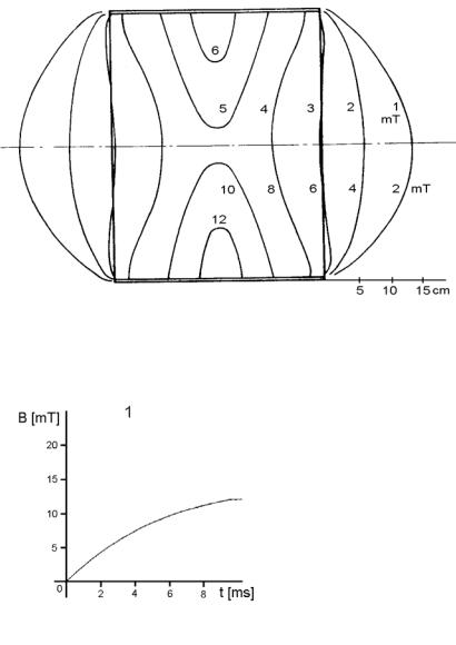
BIG SOLENOID (1) |
|
Dimensions: |
500x330 mm diam. |
Weight: |
6.1 kg |
Inductance: |
48 mH |
Resistance: |
7.8 Ω |
Max. voltage: |
80 V |
Max. current: |
8 A |
Max. power: |
100 VA |
Max. temperature: |
45 C |
Insulation: |
class II |
Environment: |
standard |
The applicator is constructed as cylindrical coil. Chassis and cover are made of hard polystyrene that forms additional insulation. Internal part of applicator is upholstered. Movable outlet is provided by rubber outlet.
Fig. 1 shows levels of magnetic induction, valid for all intensity values. The numbers relate to maximum actuation of applicator. The higher values relate to use without adapter plug, the lower values relate to use with adapter plug. Electrical current induced in tissues is in direct relation to speed of change of magnetic induction shown at fig. 2.
Fig. 1: Big solenoid
Fig. 2: Big solenoid
page 10 of 42
BTL - 09 |
user manual & user's guide |
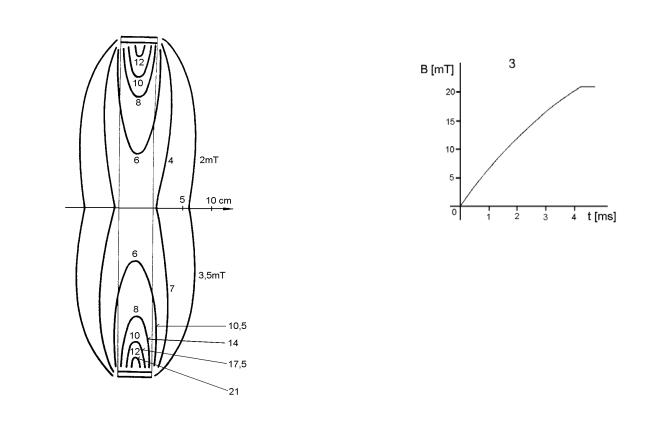
SMALL SOLENOID (2) |
|
Dimensions: |
300x330 mm diam. |
Weight: |
5.2 kg |
Inductance: |
23 mH |
Resistance: |
5.3 Ω |
Max. voltage: |
80 V |
Max. current: |
8 A |
Max. power: |
85 VA |
Max. temperature: |
45 C |
Insulation: |
class II |
Environment: |
standard |
The applicator is constructed as cylindrical coil. Chassis and cover are made of hard polystyrene that forms additional insulation. Internal part of applicator is upholstered. Movable outlet is provided by rubber outlet.
Fig. 1 shows levels of magnetic induction, valid for all intensity values. The numbers relate to maximum actuation of applicator. The higher values relate to use without adapter plug, the lower values relate to use with adapter plug. Electrical current induced in tissues is in direct relation to speed of change of magnetic induction shown at fig. 2.
Fig. 1: Small solenoid
Fig. 2: Small solenoid
page 11 of 42
BTL - 09 |
user manual & user's guide |
RING (3) |
|
Dimensions: |
300x60 mm diam. |
Weight: |
2.7 kg |
Inductance: |
36 mH |
Resistance: |
4.2 Ω |
Max. voltage: |
80 V |
Max. current: |
7 A |
Max. power: |
33 VA |
Max. temperature: |
45 C |
Insulation: |
class II |
Environment: |
standard |
The applicator is constructed as self-supporting coil with double insulation.
Fig. 1 shows setting of levels of magnetic induction, valid for all intensity values. The numbers relate to maximum actuation of applicator. The higher values relate to use without adapter plug, the lower values relate to use with adapter plug.
Electrical current induced in tissues is in direct relation to speed of change of magnetic induction shown at fig. 2.
Fig. 1: Ring
max. intensity if adapter plug is used
max. intensity
Fig. 2: Ring
page 12 of 42
BTL - 09 |
user manual & user's guide |
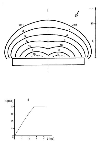
DISC (4) |
|
Dimensions: |
240x240 mm |
Weight: |
2.1 kg |
Inductance: |
29 mH |
Resistance: |
3.2 Ω |
Max. voltage: |
80 V |
Max. current: |
6 A |
Max. power: |
22 VA |
Max. temperature: |
45 C |
Insulation: |
class II |
Environment: |
standard |
The applicator is constructed as self-supporting flat coil built-in to both-side upholstered pillow.
Fig. 1 shows setting of levels of magnetic induction, valid for all intensity values. The numbers relate to maximum actuation of applicator. The higher values relate to use without adapter plug, the lower values relate to use with adapter plug.
Electrical current induced in tissues is in direct relation to speed of change of magnetic induction shown at fig. 2.
max. intensity |
max. intensity if adapter plug is used |
Fig. 1: Disc
Fig. 2: Disc
page 13 of 42
 Loading...