


BTL-5000 SWT Series
SERVICE USER GUIDE
101PL01/12/2008EN

CONTENT |
|
|
1 |
USER'S MANUAL.................................................................................................................................. |
3 |
2 |
THERAPEUTIC ENCYCLOPAEDIA.................................................................................................... |
50 |
3 |
SERVICE MENU MANUAL.................................................................................................................. |
65 |
4 |
TROUBLE-SHOOTING........................................................................................................................ |
86 |
5 |
PROCESS OF UPLOAD OF APPLICATIONS FROM PC BY SERIAL LINE |
|
|
- FOR END USERS ............................................................................................................................. |
89 |
6 |
PROCESS OF UPLOAD OF APPLICATIONS FROM PC BY SERIAL LINE |
|
|
- FOR SERVICE................................................................................................................................... |
94 |
7 |
PROCESS OF UPLOAD OF APPLICATION IN THE SWT COMPRESSOR UNIT FROM PC BY |
|
|
SERIAL LINE - FOR SERVICE......................................................................................................... |
100 |
8 |
OUTPUT CONTROL.......................................................................................................................... |
106 |
9 |
BLOCK DIAGRAM............................................................................................................................. |
110 |
10 |
CABLES............................................................................................................................................. |
113 |
11 |
LIST OF COMPONENTS................................................................................................................... |
127 |
12 |
ELECTRICAL SHEETS AND DRAWINGS........................................................................................ |
130 |
13 |
ASSEMBLY DRAWINGS................................................................................................................... |
137 |

BTL-5000
Shockwave Series
USER‘S MANUAL
101IE30/07/2008EN

BEFORE YOU START
Thank you for showing your interest and buying our device the BTL5000 SWT Series. We hope you will be satisfied and thanks to you, this device will help many patients.
All of us at BTL wish you every success with your BTL5000 SWT Series. We pride ourselves on being as responsive as possible to our customers’ needs. Your suggestions and comments are always welcome since we believe an ongoing relationship with our customers is critically important to our future product line. Please call or email us your suggestions.
While we would like you to start using your equipment right away, we encourage you to thoroughly read this manual in order to fully understand the operational features of the BTL-5000 SWT system.
Again, thank you for being a BTL customer. In the event of any problem, or if you require service, please make an initial call to your local distributor, who will decide whether to refer the problem to our office.
PAGE 2 OF 47

CONTENTS
1 |
|
GENERAL CHARACTERISTICS OF THE DEVICE....................................................................................... |
5 |
1.1 |
BTL – 5000 SWT System Series .................................................................................................................. |
6 |
|
1.2 |
Shockwave and Its Character....................................................................................................................... |
6 |
|
1.3 |
|
Shockwave Generation................................................................................................................................. |
7 |
1.3.1 |
Ballistic Principle of the Shockwave Generation ...................................................................................... |
7 |
|
1.4 |
Biological Effects of the Shockwave ............................................................................................................. |
7 |
|
1.5 |
Advantages of the Shockwave Treatment .................................................................................................... |
8 |
|
1.6 |
Possible Side Effects After the Shockwave Treatment................................................................................. |
8 |
|
1.7 |
Indications for the Shockwave Treatment..................................................................................................... |
8 |
|
1.8 |
Contraindications to the Shockwave Treatment ........................................................................................... |
9 |
|
2 |
|
INSTRUCTIONS FOR USE.......................................................................................................................... |
10 |
2.1 |
Front Panel of the BTL5000 SWT............................................................................................................. |
10 |
|
2.2 |
Rear Panel of the BTL5000 SWT ............................................................................................................. |
11 |
|
2.3 |
Assembly and Putting into Operation.......................................................................................................... |
12 |
|
2.4 |
|
OPERATING THE DEVICE ........................................................................................................................ |
14 |
2.4.1 |
Touch Screen......................................................................................................................................... |
14 |
|
2.4.2 |
Numeric Keypad..................................................................................................................................... |
15 |
|
2.5 |
|
Therapy (Setting Principle) ......................................................................................................................... |
16 |
2.5.1 |
Diagram of the Therapy Setting Process................................................................................................ |
16 |
|
2.5.2 |
Welcome Screen and Selection of Channels, Tabs and Accessories .................................................... |
17 |
|
2.5.3 |
Setting Therapy Parameters Via the ‘diag’ Button.................................................................................. |
18 |
|
2.5.4 |
Setting Therapy Parameters Via the 'prog' Button ................................................................................. |
18 |
|
2.5.5 |
Setting Therapy Parameters Manually (User Setup) Via the ‘man' Button ............................................. |
19 |
|
2.5.6 |
Therapy Parameters Screen – Ergonomic, Standard and Expert Mode................................................. |
20 |
|
2.5.7 |
Setting Number of Shocks...................................................................................................................... |
20 |
|
2.5.8 |
Setting Therapy Intensity........................................................................................................................ |
20 |
|
2.6 |
|
Course of Therapy...................................................................................................................................... |
20 |
2.6.1 |
Start - Interruption - End of Therapy....................................................................................................... |
20 |
|
2.6.2 |
Running Therapy Screen ....................................................................................................................... |
22 |
|
2.7 |
|
Therapy Parameters................................................................................................................................... |
22 |
2.8 |
|
Encyclopaedia ............................................................................................................................................ |
22 |
2.9 |
|
Therapy Saving .......................................................................................................................................... |
23 |
2.9.1 |
Save Therapy and Add It to the Client Data ........................................................................................... |
24 |
|
2.9.2 |
End of Therapy / Shock Generation ....................................................................................................... |
25 |
|
3 |
|
DEVICE MENU............................................................................................................................................. |
26 |
3.1 |
|
Accessories ................................................................................................................................................ |
26 |
3.1.1 |
Installation of Accessories...................................................................................................................... |
26 |
|
3.1.2 |
Information about Accessories ............................................................................................................... |
26 |
|
PAGE 3 OF 47

3.1.3 |
|
Information about Connectors ................................................................................................................ |
26 |
|
3.2 |
|
|
Unit Settings ............................................................................................................................................... |
27 |
3.2.1 |
|
Password Setting ................................................................................................................................... |
27 |
|
3.2.2 |
|
Sound Setting......................................................................................................................................... |
27 |
|
3.2.3 |
|
Screen Saver and Auto Switch-Off......................................................................................................... |
28 |
|
3.2.4 |
|
Colour Setting ........................................................................................................................................ |
28 |
|
3.2.5 |
|
Setting of Display Contrast..................................................................................................................... |
28 |
|
3.2.6 |
|
Date and Time Setting............................................................................................................................ |
28 |
|
3.2.7 |
|
Language Setting ................................................................................................................................... |
28 |
|
3.2.8 |
|
Operation Mode...................................................................................................................................... |
28 |
|
3.2.9 |
|
Touch Panel Calibration......................................................................................................................... |
28 |
|
3.2.10 |
User Options .......................................................................................................................................... |
28 |
||
3.2.11 |
Style of Operation................................................................................................................................... |
29 |
||
3.2.12 Setting of HW Key.................................................................................................................................. |
29 |
|||
3.2.13 |
Unit Information...................................................................................................................................... |
29 |
||
3.2.14 |
Unlock Code........................................................................................................................................... |
29 |
||
3.2.15 |
Service Functions................................................................................................................................... |
29 |
||
3.3 |
|
|
Specific Settings ......................................................................................................................................... |
30 |
3.3.1 |
|
Shockwave Setting................................................................................................................................. |
30 |
|
3.3.2 |
|
Applicator Kit Replacement Wizard........................................................................................................ |
31 |
|
4 |
|
USER OPTIONS........................................................................................................................................... |
32 |
|
4.1 |
|
|
Clients......................................................................................................................................................... |
32 |
4.2 |
|
|
User Sequences ......................................................................................................................................... |
32 |
4.3 |
|
|
User Diagnoses/Programs.......................................................................................................................... |
33 |
4.4 |
List of Recent Therapies............................................................................................................................. |
33 |
||
5 |
|
APPLICATION OF SHOCKWAVES............................................................................................................. |
34 |
|
6 |
|
ACCESSORIES............................................................................................................................................ |
36 |
|
7 |
|
MAINTENANCE AND SAFETY INSTRUCTIONS........................................................................................ |
37 |
|
7.1.1 |
|
Shock Transmitter Replacement Procedure........................................................................................... |
38 |
|
7.1.2 |
|
Procedure of Worn-out Tube and Projectile Replacement ..................................................................... |
39 |
|
7.2 |
Safety of the Device.................................................................................................................................... |
42 |
||
7.3 |
|
|
Warranty Conditions ................................................................................................................................... |
43 |
8 |
|
TECHNICAL PARAMETERS ....................................................................................................................... |
44 |
|
8.1 |
|
|
Applicable Standards.................................................................................................................................. |
45 |
8.2 |
|
|
Manufacturer .............................................................................................................................................. |
46 |
9 |
|
DEVICE CONFIGURATION ......................................................................................................................... |
47 |
|
PAGE 4 OF 47

1GENERAL CHARACTERISTICS OF THE DEVICE
The BTL -5000 SWT Series is a modern device enabling the application of therapies by using no invasive shockwaves. Shockwaves are one of the most effective ways of treatment of pain connected to the musculoskeletal system. Today, this is the second most frequent reason of absence from work.
The devices are equipped with a colour touch screen on the main unit, and considerably simplifies the use of the device. The touch screen is equipped with a touch pen for easy operation of the device. A vertically positioned device enables you to see the information on the screen clearly from different servicing positions. In addition, the brightness of the display can be adjusted to suit the light conditions in the office or the health centre. The information displayed on the screen will guide you throughout the whole therapy, simply adjust the parameters by pressing the touch screen buttons and turning the knobs on the device.
Selecting a diagnosis from a list of alphabetically organized treatment protocols, or selecting a program, will make an easy and efficient start to the therapy. You can adjust any treatment parameter manually by the simple use of the touch screen buttons. Throughout the whole therapy, the device informs you about the therapeutical method used, type of treatment, number of applied shocks, total and remaining shocks, frequency used, intensity and other necessary data.
Save your time by using the predefined programs of the main unit. Based on detailed research and practical use of the device, the well-organized predefined protocols will present recommendations for treatment of various conditions.
The BTL5000 SWT allows you to insert the names of your clients and other relevant information into the internal memory of the device and connect the client data with predefined or your own protocols. When your clients call again, simply recall their name and apply the pre-set therapy.
With every BTL-5000 SWT you can purchase a trolley specially designed for the BTL products. Its design offers maximum comfort of storage and use of the device. Four steady wheels provide simple movement of the device in the office or the health care centre.
The trolley includes a range of accessory containers and baskets.
Please visit our corporate website at http://www.btlnet.com for the latest information on BTL products and services.
GENERAL CHARACTERISTICS OF THE DEVICE | PAGE 5 OF 47

1.1BTL – 5000 SWT SYSTEM SERIES
The device consists of three units: the main unit, the compressor unit and the applicator.
Main system – BTL5000 unit, which includes the main microcomputer and software for control of the whole equipment, including user encyclopaedia and the therapy guide.
Compressor – apart from the compressor there is also the complete electronics attached for the regulation of the ballistic pressure.
Applicator – ergonomical applicator simplifies the „course of" the therapy, following the instructions of the main unit.
The system enables the connection of two applicators. Each applicator can contain a different transmission element, differing in its size and characteristic. Thereby the system features an advantage of service abilities for two different therapies, with no need to change the transmission elements. However, only one applicator can be active at a time. It is not possible to use two applicators together, at the same time.
1.2SHOCKWAVE AND ITS CHARACTER
The shockwave is defined as a wave with a rapid increase of pressure in a very short time and gradual decline with a phase of small negative pressure.
Shockwaves are aimed at the affected areas that are the cause of chronic pain. The influence of shockwaves leads to for example dissolution of calcic deposits and better vascularisation, and in its final effect it causes relief of pain.
Outside the client's body (extracorporeally), a pressure pulse with a high amplitude is generated, and its energy is concentrated into the target area in the body. The pressure pulse without major losses travels through a water medium to the client and penetrates soft tissue.
The pressure course of the shockwave in time expressively differs from the pressure course of the harmonic sound wave. The shockwave is compared to the ultrasonic waves particularly characterized by a pressure jump change, higher amplitude and non-periodicity.
In the shockwave, the positive amplitude is generally much bigger than the negative amplitude. The frequency rate of the shockwaves is usually low (Hz units) and eventual cavitation (disturbance of material consistency – rise of cavities) will relax. Consequently there is no threat of energy exhaustion on cavitations as in the case of continuous ultrasound.
A substantial part of the shockwave energy penetrates into liquid (of the organism) with a great positive pressure pulse. Its diffusion is only limited by the actual tissue absorption and eventual reflections on acoustic inhomogeneities.
The shockwave is defined as a pressure pulse with these characteristics:
•High positive pressure amplitude – 10 to 1000 MPa = 100 to 1000 Bar (100x atmospheric pressure)
•Low negative pressure amplitude – 1 to 10 MPa
•Short time duration – 1 μs to 20 μs
•Rapid pressure increase – < 100 ns
•Broad frequency spectrum – 1 Hz to 1 MHz
GENERAL CHARACTERISTICS OF THE DEVICE | PAGE 6 OF 47

For therapeutical application, these values are lower, especially the maximum pressure amplitude, which is about 15 MPa, pulse length is 10 to 20 μs, and frequency of the applied shockwave is 1 to 25Hz. The treatment is generally carried out without local anaesthetic and lasts about 15 to 30 minutes. During the first week after the treatment, the client should avoid all activities that could excessively strain the treated area.
1.3SHOCKWAVE GENERATION
Several types of generators were developed for the shockwave therapy, providing shockwaves with varied characteristics. Shockwaves in their time span and spatial arrangement carry the imprint of the generation method.
The BTL 5000 SWT uses the ballistic principle of the shockwave generation.
1.3.1BALLISTIC PRINCIPLE OF THE SHOCKWAVE GENERATION
A pressure wave is formed via a projectile by accelerated compressed air, which is generated by an electronically controlled ballistic-pressure compressor. Using elastic impact, the kinetic energy of the projectile is transferred into a probe of the applicator and into the client's body via this probe. Consequently, during the treatment, the end of the applicator must be in immediate contact with the skin and subcutaneous tissue.
1.4BIOLOGICAL EFFECTS OF THE SHOCKWAVE
The shockwave effects mainly occur at sites, where there is a change in impedance, such as the bone-soft tissue interface.
There is an improvement of regeneration and repair of tissues in the following areas and achievement of the following effects:
cellular effect – increase in transmittance of a cell membrane (improvement of ionic channels activity), stimulation of cell division, stimulation of cellular cytokines production,
reproduction of vessels in the area of tendons and muscles, improvement of blood circulation and MTBincrease in concentration of growth factor beta 1 – chemotactic and mitogenic effect on osteoblasts,
effect on nitrogen oxide system (bone healing and re-modelling),
improvement of micro - circulation and metabolism,
dissolution of calcic fibroblasts,
support of collagen production,
reduction of tissue tension,
analgetic effect:
destruction of afferent nerves and nerve receptors,
CNS stimulants, sensed as pain; are also inflammation transmitter substances,
regression of pain caused by local ischemia,
gate control theory of pain.
GENERAL CHARACTERISTICS OF THE DEVICE | PAGE 7 OF 47

1.5ADVANTAGES OF THE SHOCKWAVE TREATMENT
by targeted operation of the shockwave, strain of surrounding tissues is quite insignificant
the body is not strained by pharmaceuticals (except a short term effect of local anaesthesia)
possibility to prevent from necessity of surgical intervention and relevant hazard
thanks to ambulatory treatment the absence from work reduces to a minimum, as well as the absence from training routine of sportsmen
for some indications (e.g. tennis elbow) there is basically no other effective treatment
1.6POSSIBLE SIDE EFFECTS AFTER THE SHOCKWAVE TREATMENT
erythema or swelling can temporarily occur in the treated area
loss of bodily sensation or itching can temporarily occur in the treated area
momentary increase of pain can appear immediately after the treatment
haematoma
petechia
skin damage after previous corticoid therapy
shockwave application can cause undesirable heart activity
1.7INDICATIONS FOR THE SHOCKWAVE TREATMENT
plantar fasciitis
achillodynia – achillobursitis
inflammations and calcification of shoulder joint tendons
pain in the groin area
epicondylitis (tennis and golf elbow)
the apex patellae syndrome and tibial stress syndrome
pain in the area of the hip and the iliotibial tract
jumper's knee / patellar tendinitis
pain in the hamstring insertions
pain on the palmar side of the wrist
exostoses of small hand joints in case of grade 1 arthrosis
acupuncture
pain trigger points - painful points in muscles
GENERAL CHARACTERISTICS OF THE DEVICE | PAGE 8 OF 47
1.8CONTRAINDICATIONS TO THE SHOCKWAVE TREATMENT
application to certain tissues (eyes and their surroundings, myocardium, spinal cord, gonad, kidneys, liver)
coagulation of blood disorders
polypus in the area of treatment
pregnancy
coagulation of blood disorders and the use of anticoagulants
thrombosis
tumour disease
polyneuropathy
acute inflammation
growing cartilage in children
therapy using corticoids
inapplicable in areas and organs with possible gas content
inapplicable on areas in proximity to large nerves, vessels, spinal cord and head
GENERAL CHARACTERISTICS OF THE DEVICE | PAGE 9 OF 47
2INSTRUCTIONS FOR USE
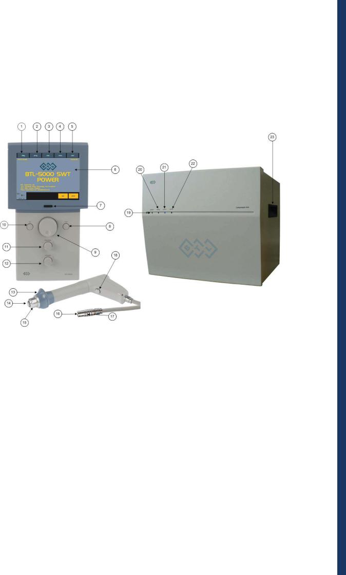
2.1FRONT PANEL OF THE BTL5000 SWT
1.diag button to select diagnosis
2.prog button to select therapy program
3.man button to set therapy parameters manually
4.menu button (to set date, time, language, display contrast, sounds, user options, etc.)
5.user button (lists of clients, user diagnoses, programs and sequences, recent therapies, etc.)
6.touch screen
7.ON/OFF power switch (“ON” status indicated by the blue backlight)
8.enter key (to confirm selection or setting)
9.select knob (to select and set individual parameters)
10.esc key (to cancel selection or setting and return to the previous status)
11.time / stop knob (to set therapy time, and to start and stop therapy)
12.intensity knob (to set intensity)
13.hand rest of the applicator
14.shock transmitter of the applicator
15.shock transmitter screw cap of the applicator
16.connector of the applicator
17.guide mark of the connector
18.applicator button for therapy start
19.power activation indicator of the compressor
20.indicator signalling - ready to generate shockwaves ready
21.active tab indicator for the applicator output out A
22.active tab indicator for the applicator output out B
23.handles for easy transport of the compressor unit
BTL-5000 SWT USER’S MANUAL | PAGE 10 OF 47

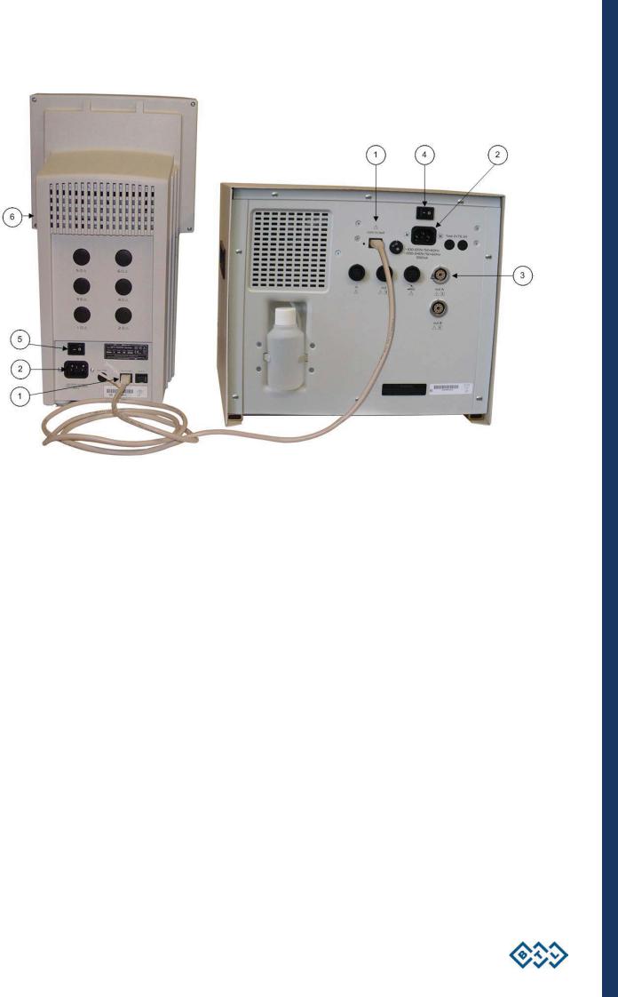
2.2REAR PANEL OF THE BTL5000 SWT
24.dummy plugs of the connectors
25.mains switch to switch the main unit on/off
26.socket for connection of the mains cable 230 V (or115 V) to the main unit
27.line fuse of the main unit
28.power switch 230V / 115V (bottom part of the main unit)
29.label with serial number and production date
30.com in - communication link input for the main unit (for servicing purposes only)
31.com in / out - communication link connector between the main unit and the compressor
32.type plate - showing device type, manufacturer and safety precautions and warning signs
33.ventilation louver
34.communication link input / output for the compressor unit
35.ON / OFF power switch for the compressor unit
36.socket to connect the mains cable 230 V (or 115 V) to the compressor unit
37.line fuses of the compressor unit
38.power switch 230V / 115V of the compressor unit
39.connectors for the shockwave applicators
40.input for connection of foot pedal
41.communication connectors (for servicing only)
42.catchment container
INSTRUCTIONS FOR USE | PAGE 11 OF 47

2.3ASSEMBLY AND PUTTING INTO OPERATION
Inspect the package and in case of any damage report it to the delivery service or your distributor. Do not proceed with installation or assembly if the package is damaged.
Unpack the device and place it on a stable horizontal surface suitable for the weight of the device. Always position the unit out of direct sunlight. The device heats up therefore it must be placed away from a direct heat sources such as radiators or room heaters. Cooling of the equipment is provided for by forced air circulation. Cooling vents are located on the rear panel and at the bottom of the BTL-5000 SWT and must not be covered. Do not position the device on a soft surface as it may obstruct the air flow to the bottom cooling vents. Do not put any objects producing heat or containing water or other liquid on the top of the device. Do not place the device close to equipment producing strong electromagnetic, electric or magnetic field (diathermy, X-rays, etc.), as the electronic systems of the device could be undesirably influenced. In case of any questions please call your authorised BTL distributor.
Retain the original packaging to ensure the eventual safe transportation of the device.
Attaching the accessory holder:
Remove the protective caps from the holes on a side of the device. Use a screwdriver to gently slide the blade under the cap and take it out. Align the accessory holder and secure it with two screws from below.
Installation of supports on the compressor unit:
The supports are only installed if the compressor unit will not sit on the cart (different legs are supplied with the cart).
The BTL-5000 e-stim SWT package includes compressor unit legs, which prevent the unit from moving during therapy.
Screw the supports according to the following picture.
.
INSTRUCTIONS FOR USE | PAGE 12 OF 47
1. Connection of the BTL -5000 SWT main unit with the compressor is accomplished by connecting the communication cable to the input/output of the communication link on the relevant unit. Plug the communication cable into the link connector on the main unit (31) and into the link connector (34) on the unit of the compressor.
2. At first connect the shockwave compressor to the socket and then the main unit of the BTL -5000 SWT device.
Plug the device directly into the mains socket. Do not use any multi-connection extension cables or
adapters.
Check the correct mains voltage - 230 V (or 115 V)
Before the first connection of the device to the mains, it is necessary to check if both the mains voltage switches (26 and 28) are in the position corresponding to local voltage standards, (either in the position 230V or 115V). For details, see the note “Switching the device to different mains voltage“ in the chapter
MAINTENANCE AND SAFETY INSTRUCTIONS. In case of any questions please call your BTL distributor.
3. Connect the supplied accessories step by step to the output connectors (39) on the rear panel of the shockwave compressor as follows (item No. 3 on the picture):
Turn the connector of the applicator so the red spot on its end is in direct line with the red spot on the output connector of the shockwave compressor and then plug the connector in.
INSTRUCTIONS FOR USE | PAGE 13 OF 47

WHEN DISCONNECTING THE CONNECTOR, hold the grooved end part of the
applicator of the connector with your fingers, slowly pull the connector towards you
and disconnect it carefully.
WARNING!!! DO NOT TURN THE WHOLE CONNECTED CONNECTOR BY
FORCE, AS IT CAN DAMAGE THE DEVICE!!!
The device detects the accessories, specifies the type and displays it on the screen in the appropriate tab. In the case of connecting improper accessories by mistake, a warning and help will display on the screen with instructions where to connect the appropriate accessories.
4. Activate the ON / OFF power switch of the compressor unit (35).
5. Then turn the power supply switch to switch the main unit ON/ OFF (25)
6. Press the ON /OFF switch placed on the front panel of the main unit (7)
Note:
After switching on, the device will test all its internal circuits and functions (about 10 - 15 secs) and in the case of any fault the system will signalize it and 'lock' itself into a secure mode. If this situation occurs, please call your authorised BTL distributor.
2.4OPERATING THE DEVICE
2.4.1TOUCH SCREEN
The touch screen can display several graphic items, some of them are only informative, some can be pressed and thereby activated. See the following basic items:
soft buttons (can be pressed to change the indicated values )
informative text
channels tabs (switching between the channels and selection)
The items on the touch screen can be pressed by a finger or by using a special pointer with a soft tip, so - called touchpen, which is included in the accessories of the device. The touch screen must not come in contact with any sharp objects, ball pens etc.
Selected channel
The BTL -5000 SWT Series allows the connection of up to two applicators, but only one can be active. Only one so-called "selected channel" can be operated at a time. The selected channel has a light tab. All information on the screen and all control elements relate to this channel. The most important information about therapies on the other channels can be viewed on their tabs.
INSTRUCTIONS FOR USE | PAGE 14 OF 47
The BTL 5000 SWT does not allow the use of two applicators at the same time. Each applicator can contain a different transmission item, differing in its size. This brings the advantage of applicability for two different therapies without the need to change the transmission elements.
Information
Channel marking: W = shockwave
1 = No. of generator
Tab of the selected channel
Information about connected accessories
Soft buttons of the menu
Soft buttons (for therapy on the selected channel)
Buttons with the same function as (8) and (10)
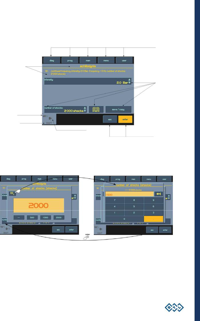
2.4.2NUMERIC KEYPAD
In addition to setting the numerical values with the select knob (9) on all the screens, you can also use the „numeric keypad" for quicker setting.
Icon to open the window with the numeric keypad: 
Press the numeric keypad button to display the window with the numeric keypad for the parameter with the light button (on the picture: the button - number of shocks - 2000). Set the required values and return to the previous screen by pressing the enter (8) button. If you do not want to enter any values or change the selected parameter, leave the window with the numeric keypad by pressing the esc (10) button.
If you enter a value out of the allowed range of values (stated above the entering box) or the device cannot set it, then the value is rounded to the nearest lower allowed value.
INSTRUCTIONS FOR USE | PAGE 15 OF 47
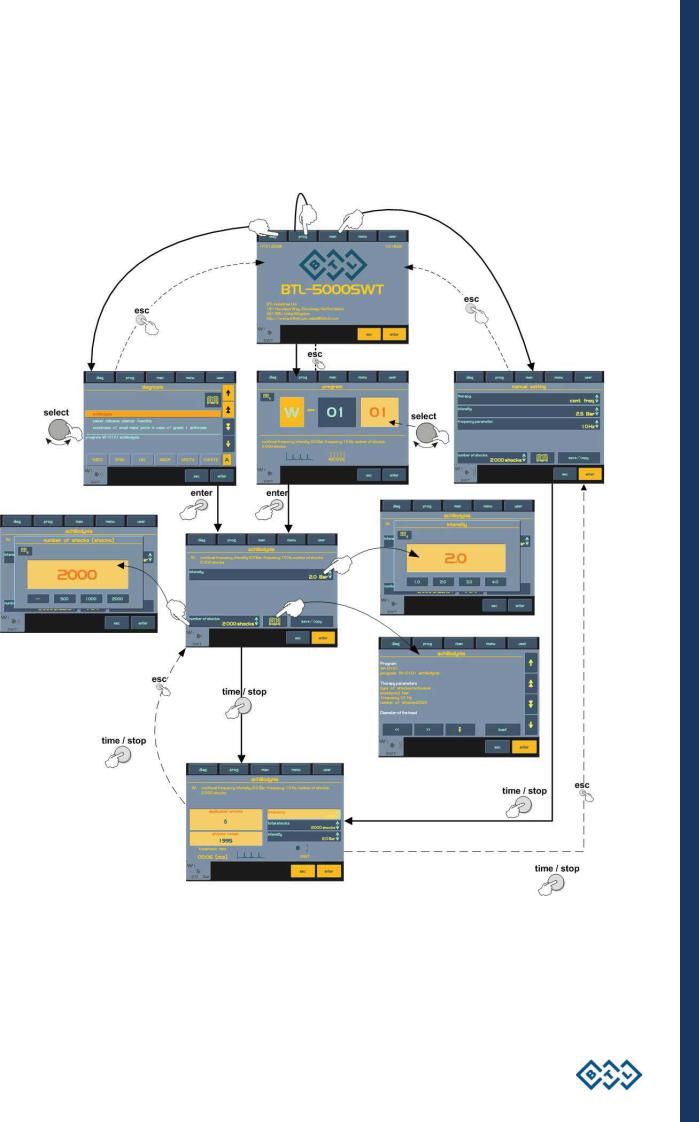
2.5THERAPY (SETTING PRINCIPLE)
2.5.1DIAGRAM OF THE THERAPY SETTING PROCESS
ENTRY
SCREEN
DIAGNOSIS |
|
MANUÁL |
SELECTION |
PROGRAM SELECTION |
SETTING |
THERAPY
INTERRUPTION
THERAPY START
RUNNING
THERAPY
THERAPY
INTERRUPTION
INSTRUCTIONS FOR USE | PAGE 16 OF 47
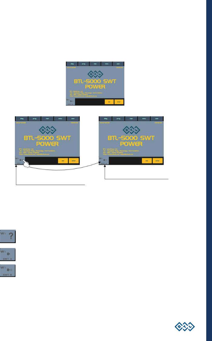
2.5.2WELCOME SCREEN AND SELECTION OF CHANNELS, TABS AND ACCESSORIES
After switching the device ON, the entry screen includes information on the channel tabs with icons of connected accessories. The number of channels - tabs dependents on the required configuration of the device. By pressing the tab, information of the actual channel displays. Information adjusted on the „invisible channels" will definitely remain saved. Almost the full screen is available for the "selected channel" - see the picture.
Switching the channels:
Tab of accessories connected to |
Tab of accessories connected to |
|
the input out B (39) |
||
the input out A (39) |
||
|
To switch between the connected accessories, press the W1 tab, see the picture. If both shockwave accessories are connected, then the channel W1 displays the tab of accessories connected to the input out A (39), and by pressing it, information on accessories connected to the input out B (39) will display.
Examples of information on the tabs:
Tab of channel W1 with no connected accessories
Tab of a selected channel W1, where the shockwave therapy can be applied with the connected accessories BTL- 214-1 (SWT A)
Tab of a selected channel W1, where the shockwave therapy can be applied with the connected accessories BTL- 214-1 (SWT B)
INSTRUCTIONS FOR USE | PAGE 17 OF 47

2.5.3SETTING THERAPY PARAMETERS VIA THE ‘DIAG’ BUTTON
A list of diagnosis will display after pressing the diag (1) button. Each tab – channel – has its own assigned list of diagnosis.
A fast search for diagnosis can be done by pressing the buttons with initial letters. For example, press the MNOP button once and all diagnosis beginning with the letter M will display. According to of the number of presses, other letters will display e.g. 2 presses of MNOP = N, 3 presses = O and 4 presses = P. The actual selected letter is displayed in the box on the right, next to the buttons.
After finding the required diagnosis, select it by pressing the enter (8) button.
Information on therapy – encyclopaedia
2.5.4SETTING THERAPY PARAMETERS VIA THE 'PROG' BUTTON
After pressing the prog (2) button, a screen will display, where a number of the required therapy program can be entered. Numbers of the particular programs include prefix – a letter matching the selected therapy:
W – Shockwave therapy.
Switching between the two parts of the program number
For faster entry of the program number, you can also use the numeric keypad – for more details see the chapter
Numeric keypad.
INSTRUCTIONS FOR USE | PAGE 18 OF 47
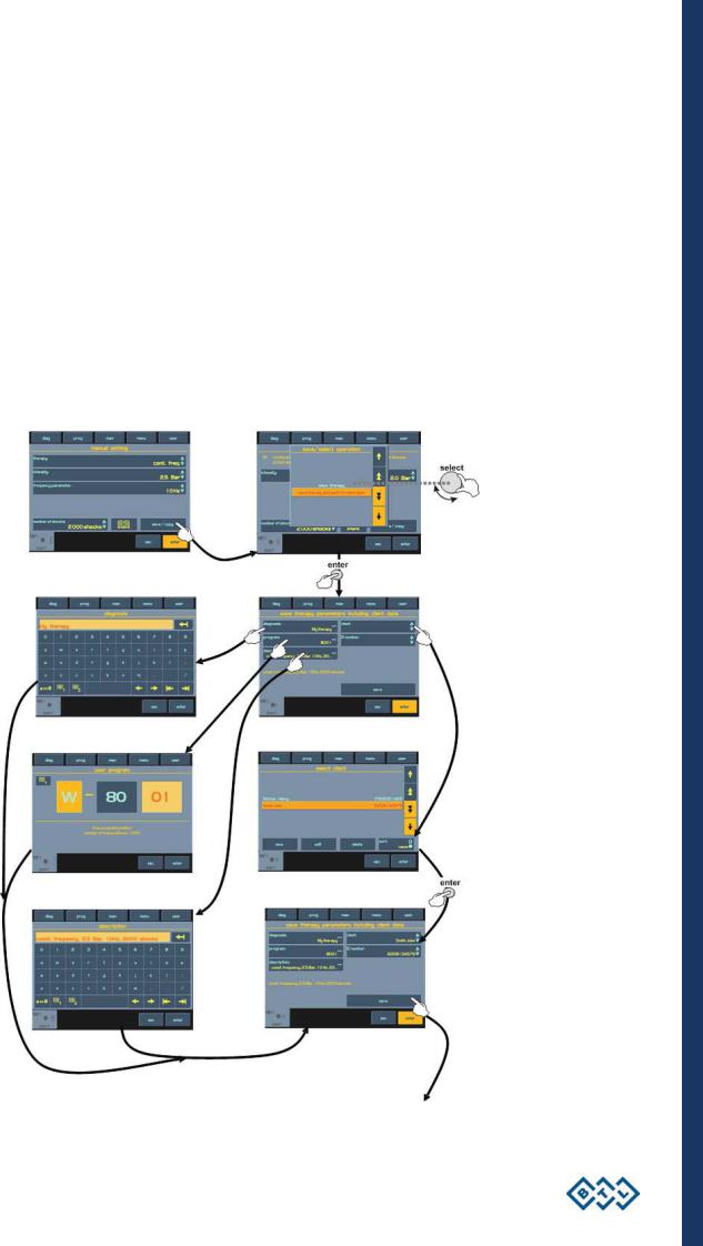
2.5.5SETTING THERAPY PARAMETERS MANUALLY (USER SETUP) VIA THE ‘MAN' BUTTON
The screen of the therapy parameters for the user (manual) setting will display by pressing the man (3) button. All specifications of the therapy can be adjusted and possibly saved as the user program or the diagnosis.
By pressing the particular soft buttons, the actual menus and setup dialogs will appear. The majority of dialogs include illustrations and symbols. See the option diagram of individual settings in this mode:
THERAPY START
INSTRUCTIONS FOR USE | PAGE 19 OF 47
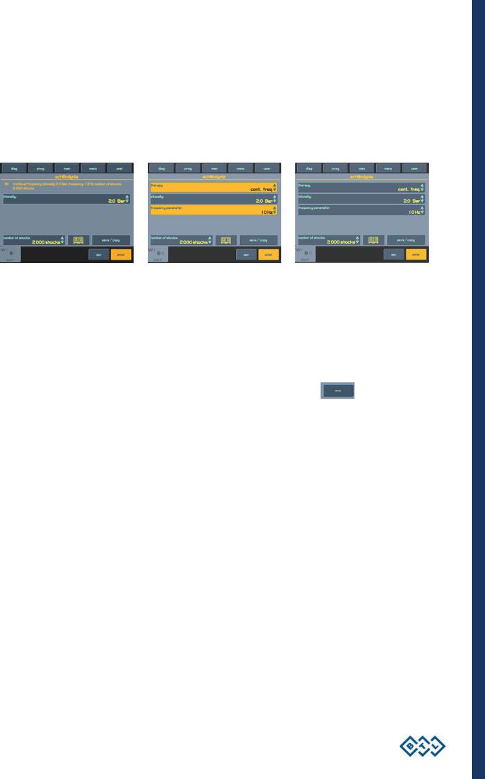
2.5.6THERAPY PARAMETERS SCREEN – ERGONOMIC, STANDARD AND EXPERT MODE
This screen always opens before the start of therapy, by pressing the diag (1) or prog (2) buttons (see Diagram of the therapy setting process). The screen either shows the most important parameters of the therapy – you have selected the ergonomic operation mode, or is shows all information on the therapy – you have selected the expert or standard operation mode. In addition, the expert mode can modify all the parameters.
The differences between the modes are apparent from the following pictures:
Ergonomic mode |
Standard mode |
Expert mode |
The operation mode can be set in the menu of the device by pressing menu (4) – for more details see the chapter
Operation mode. The expert operation mode can be entered from any mode by the quick selection – press the
man (3) button.
2.5.7SETTING NUMBER OF SHOCKS
The total number of shocks for the therapy can be adjusted on screen of the therapy parameters, even during the therapy course. The number is set either by pressing the button - number of shocks, or quick selection – by turning the select (9) knob.
With the button number of shocks you can select "endless therapy" - see the picture
The endless therapy includes an infinite number of shocks, that can be applied at the start of the therapy (end of therapy is not limited by marginal number of shocks).
2.5.8SETTING THERAPY INTENSITY
The intensity (power) of the shockwave therapy can be only adjusted on the screen of the therapy parameters, even during the therapy course. The intensity is adjusted either by pressing the intensity button or quick selection
– by turning the intensity (12) knob.
To enter the quick mode of intensity setting, press the intensity knob and turn it at the same time – the adjusted
intensity changes much faster.
2.6COURSE OF THERAPY
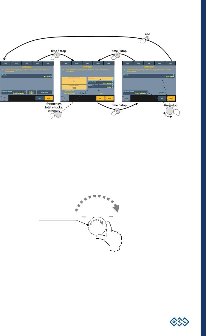
2.6.1START - INTERRUPTION - END OF THERAPY
Start the therapy by pressing time / stop (11). The therapy can start only, if the channel screen displays the therapy parameters and all the parameters are adjusted correctly. The device will signalize possible discrepancies.
INSTRUCTIONS FOR USE | PAGE 20 OF 47
|
|
End of interrupted |
|
|
therapy |
|
|
Start of interrupted |
|
Therapy START |
therapy |
Therapy parameters |
Running therapy |
Paused therapy |
screen |
screen |
screen |
Setting frequency, |
|
|
number of shocks and |
Therapy interrupt. |
Adjusting number of |
therapy intensity |
|
shocks and intensity |
|
|
during interruption |
Interrupted therapy – paused therapy – can be restarted by pressing the time / stop key and can be finished by pressing esc (10).
In pause – interrupted therapy – the parameters of intensity and total number of applied shocks can be modified by turning the time / stop (11) knob.
The intensity can be also changed during the therapy by turning the intensity (12) knob to the right – to increase the intensity, or to the left – to decrease the intensity. For a quicker intensity setting, press the intensity (12) knob while turning. The intensity setting will be much faster when pressing the knob.
intensity
Direction of intensity increase
The shockwaves therapy can also be started / interrupted by the button, located on the shockwave applicator
(18), or by the foot pedal (40). The initial setup of the button or the pedal is adjusted to AUTO. The device automatically recognizes the holdoff time of the button on the applicator, or the foot pedal and the selected method of control. If you hold the button or the foot pedal for more than 1sec, then after its subsequent release the therapy will stop (as in the continual mode, see the chapter APPLICATOR BUTTON MODE / FOOT PEDAL MODE). During the time of pressing the button or the foot pedal, generation of shockwaves will be in progress. If the button of the applicator or the foot pedal is pressed for less than 1sec, then after its release the device will be set to the option ON/OFF (see the chapter APPLICATOR BUTTON MODE / FOOT PEDAL MODE).
INSTRUCTIONS FOR USE | PAGE 21 OF 47
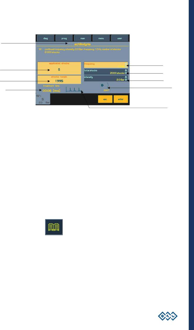
2.6.2RUNNING THERAPY SCREEN
Name of selected therapy / program and set parameters
Adjusted frequency*
No. of applied shocks
Adjusted no. of shocks
Adjusted intensity
No. of remaining shocks
Icon and name of connected
accessories
Time of applied therapy
Symbolic description of generated output
Pressing the time / stop (11) key can also start and interrupt |
the therapy |
– |
see |
the |
chapter |
Start - interruption - end of therapy. |
|
|
|
|
|
*the maximum frequency value according to the relevant configuration |
of the device |
is |
15 |
Hz or |
22 Hz |
(see more in the table in the chapter Device configuration). |
|
|
|
|
|
2.7THERAPY PARAMETERS
Each therapy can have different parameters. For each therapy, only the parameters that describe that therapy will be displayed and these parameters can be adjusted in the manual mode, after pressing the man button. An exact description of the parameters for individual therapies can be found in the relevant User's manual.
2.8ENCYCLOPAEDIA
The encyclopaedia includes information on possible therapies and examples of areas for the shockwave application. The device is always supplied with a hard copy of encyclopaedia. Its electronic format is included in the device, and is available from most screens and menus.
Icon to open the encyclopaedia:
If you open the encyclopaedia after a selection of a particular diagnosis, the existent information to the selected diagnosis will be displayed. Otherwise you will enter the contents of the encyclopaedia – the list of particular diagnosis. You can browse through the encyclopaedia by turning select (9). After the selection of the required diagnosis, you will enter the particular information about the diagnosis by pressing enter (8):
INSTRUCTIONS FOR USE | PAGE 22 OF 47

Information on diagnosis
Moving between information, if not displayed on one screen
Loading parameters of selected
diagnosis to the parameter screen
- the device is ready for therapy
Moving between diagnosis
Display of graphic information about diagnosis (e.g. therapy area)
Display of other graphic information about diagnosis (optional - skin, muscle, skeleton)
2.9THERAPY SAVING
The user can select a particular operation after pressing the save button. Depending on a selected operation, a form with the appropriate data will be revealed. An example of the procedure is displayed on the following screens.
You can save the therapy always after setting the therapy parameters – i. e. from the screen of therapy parameters – see the chapter Therapy parameters screen - ergonomic, standard and expert mode. The following information is saved for each shockwave therapy:
Frequency
Number of shocks
Intensity
When saving the therapy, enter:
Name of the diagnosis (therapy) – will be displayed in list of diagnosis under the diag (1) button
Program number – will be displayed between programs under the prog (2) button
Description, additional information – it is displayed in both lists „below the line"
INSTRUCTIONS FOR USE | PAGE 23 OF 47
You can choose the number of the saved program from the numbers 8000 to 8999. The device offers you the lowest available number. And during saving it adds a letter of the corresponding compressor belonging to the program. So the resulting number can be e.g.: W- 8001 for the shockwave therapy.
2.9.1SAVE THERAPY AND ADD IT TO THE CLIENT DATA
All therapy parameters that are saved in this item of the menu are the same as the previous item included in the therapy saving menu. The saved therapy will also appear in both lists – the list of diagnosis and the list of programs.
In addition it will also display in the list of therapies assigned to the entered client.
See the following diagram displaying the whole dialog of the therapy saving.
Set therapy parameters |
Save therapy |
Enter name of diagnosis
Enter program name |
Select client |
Enter description |
All information entered |
- must be saved |
After saving - the therapy will be displayed with the following lists (See the next page)
INSTRUCTIONS FOR USE | PAGE 24 OF 47
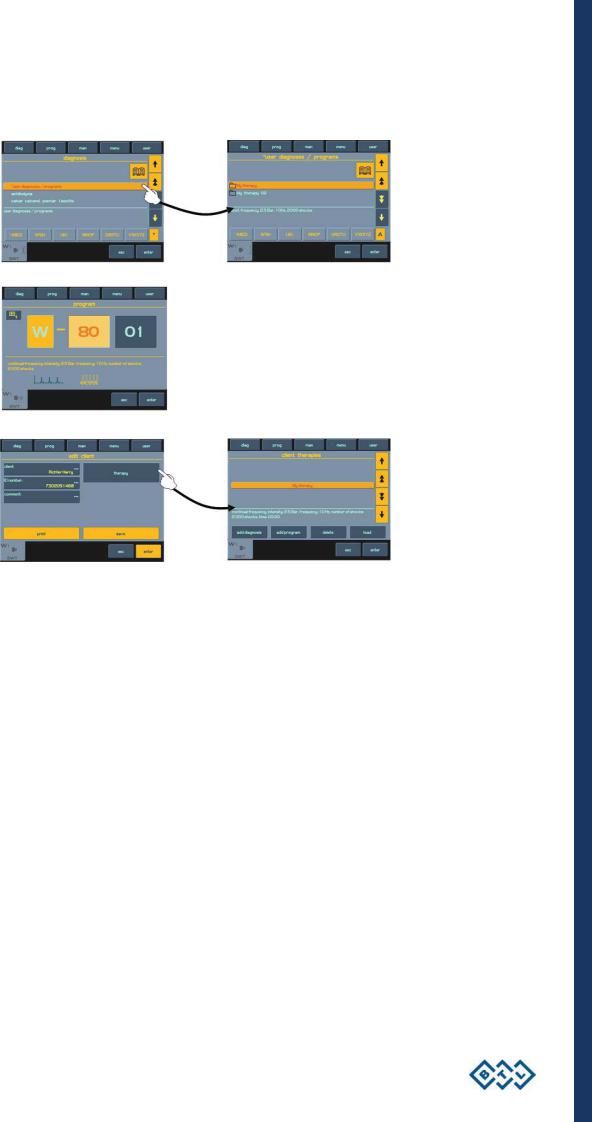
The saved therapy can be found in these lists on the relevant channel:
List of diagnosis
List of programs
List of therapies of the selected client
2.9.2END OF THERAPY / SHOCK GENERATION
On a regular basis the therapy ends after the application of the adjusted number of shocks. If, for whatever reason, you want to end or interrupt the therapy before finishing the adjusted number of shocks, it is possible to interrupt the therapy by pressing the time / stop key or the button on the applicator. To end the therapy press esc.
The generation of shocks will finish by expiry of the adjusted number of shocks applied, or it is possible to finish their generation by releasing (in a state of continual mode) / and pressing again the button of the applicator (in a state of ON /OFF mode) see the chapter Shockwave setting - applicator button mode.
INSTRUCTIONS FOR USE | PAGE 25 OF 47

3DEVICE MENU
After pressing menu (4) it is possible to browse the following offers by using the select knob:
Accessories
Encyclopaedia – see the chapter Encyclopaedia
Unit settings
Specific settings
3.1ACCESSORIES
In this submenu you can select:
Installation of accessories
Information about connected accessories
Information about the number of clients and connection of connectors on the rear panel of the device
3.1.1INSTALLATION OF ACCESSORIES
Each connected accessory has the memory that includes identification data of the actual accessory. According to this data, the device recognizes which accessory is connected, if it is compatible or not, and if the device can work with the connected accessory or not. The memory also contains a serial number of the accessory.
As the memory contains a lot of information and its downloading lasts from 30 seconds to 2 minutes, there is an installation of accessories provided for faster work of the device. After the installation, only the serial number of the accessory is downloaded from the accessory memory and the other information is read from the device memory.
During the installation process, follow the instructions on the screen. In particular:
During the installation switch off therapies on all the compressors of the device
Do not have other accessories connected than the one that is being installed (and connect it directly, not via interface cables)
These guides are necessary for decrease of electromagnetic interference that could cause improper downloading
of the memory data.
3.1.2INFORMATION ABOUT ACCESSORIES
This item of the menu displays the information about connected accessories such as Name of the accessory, its serial number etc. And mainly it displays for which generator – output / input – the accessory has been intended and the number of already applied shocks.
3.1.3INFORMATION ABOUT CONNECTORS
In the BTL - 5000 SWT, this item of the menu only includes the specification of blind / connected connectors on the rear panel of the main unit.
DEVICE MENU | PAGE 26 OF 47
3.2UNIT SETTINGS
This submenu offers the options of setting and displaying these parameters:
Password setting
Sound setting
Screen saver and auto switch-off
Colour setting
Setting of display contrast
Date and time setting
Language setting
Operation mode
Touch panel calibration
User options
Style of operation
Setting of HW key
Unit information
Unlocking code
Service functions
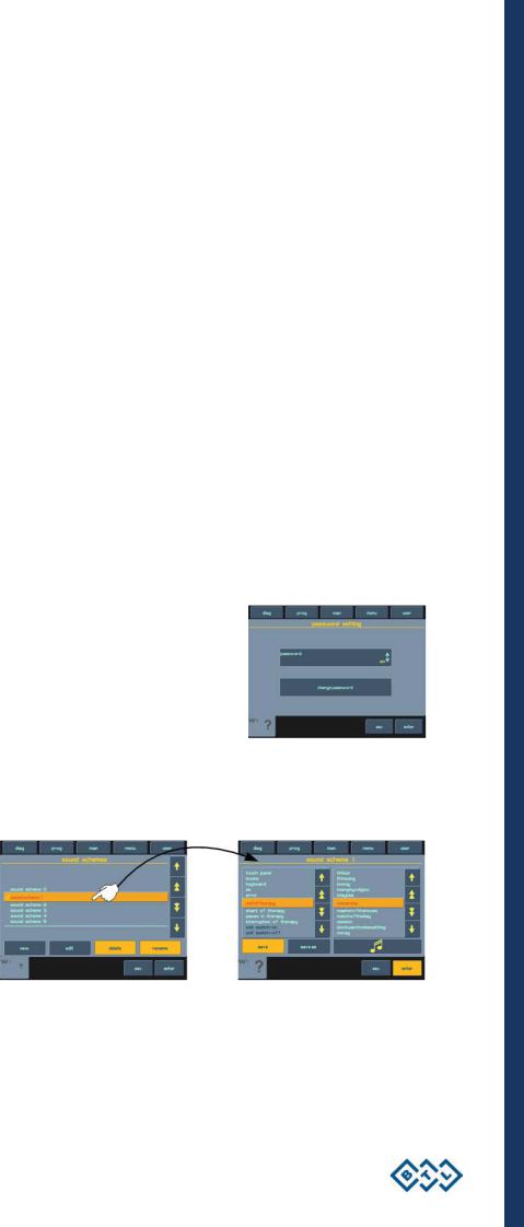
3.2.1PASSWORD SETTING
This menu can change the code - password demanded by the device when it is switched on. There is no further work with the device possible, without entering this password. As standard, the device is supplied „unlocked" – with the password switched off.
3.2.2SOUND SETTING
This includes acoustic signalling of the pressed buttons, touch panel, etc. and accomplishment of certain operations (therapy start, therapy interruption, end of therapy etc.). The device includes standard sounding as set from the manufacturer, i.e. signalling the therapy operations. All audio tones can be switched off (without tones) or modified as required.
This item can edit individual audio schemes, create new ones and modify audio tones for each operation separately.
The sound volume can be sets in the menu item User options.
DEVICE MENU | PAGE 27 OF 47
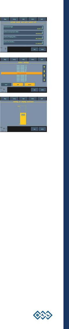
3.2.3SCREEN SAVER AND AUTO SWITCH-OFF
This includes the setup of the screen saver type, activation time of the screen saver, period of time during which the screen should be switched off and idle time of the whole device.
3.2.4COLOUR SETTING
The user can set colours of all elements displayed on the screen. There are 50 preset colour schemes available to choose from, or, if not satisfied with any of them, the user can create and save his/her own colour schemes. In the custom colour scheme, the user can step by step select individual elements.
3.2.5SETTING OF DISPLAY CONTRAST
After selecting this offer, the optimum contrast (readability) of the display can be set by turning the select (9) knob.
As the contrast of the screen depends on various factors, (such as temperature), there is a fast and direct setting of the screen contrast, by using the select (9) knob while simultaneously holding the enter (8) and esc (10) keys.
3.2.6DATE AND TIME SETTING
This allows the user to set the date and time in the device.
3.2.7LANGUAGE SETTING
Preferred language of the texts displayed in the device. As standard, English is preset by the manufacturer.
3.2.8OPERATION MODE
Select one of the three modes, see the chapter Therapy Parameters Screen – Ergonomic, Standard and Expert Mode. The ergonomic mode is preset by the manufacturer as standard.
3.2.9TOUCH PANEL CALIBRATION
If the buttons on the touch screen do not react when pressed, the touch screen needs calibration. The calibration procedure is apparent from the screen of the device. It is advisable to use the touchpen during calibration and follow the instructions, displayed on the screen of the device.
Unsuccessful calibration can always be interrupted by pressing the esc button. To verify the touch screen adjustments, use the "touch panel function test" feature.
3.2.10USER OPTIONS
Here, you can set:
Direction of movement in the menu when turning the select (9) knob
Alphabetical order of diagnosis and certain menus (from A to Z / from Z to A)
Position of the tab bar (up / down)
Sound volume
DEVICE MENU | PAGE 28 OF 47
 Loading...