

Bryant 580J Series Installation Instructions Manual

580J
SINGLE PACKAGE ROOFTOP, GAS HEATING/ELECTRIC COOLING
VERTICAL AIR FLOW UNIT WITH PURON
15, 17.5, 20, 25, 27.5 TONS -- (SIZES 17, 20, 24, 28, 30)
R
(R--410A) REFRIGERANT
Installation Instructions
NOTE: Read the entire instruction manual before starting
the installation
TABLE OF CONTENTS
SAFETY CONSIDERATIONS 2....................
Rated Indoor Airflow (cfm) 3.....................
INSTALLATION 10..............................
Jobsite Survey 10...............................
Step 1 -- Plan for Unit Location 10.................
Roof Mount 10..............................
Step 2 -- Plan for Sequence of Unit Installation 10.....
Curb--Mount Installation 10....................
Pad--Mount Installation 10.....................
Frame--Mount Installation 10...................
Step 3 -- Inspect Unit 10..........................
Step 4 -- Provide Unit Support 12..................
Roof Curb Mount 12.........................
Alternate Unit Support (In Lieu of Curb Mount) 12..
Step 5 -- Field Fabricate Ductwork 16...............
Step 6 -- Rig and Place Unit 16....................
Positioning on Curb 17.......................
Step 7 -- Install Outside Air Hood — Factory Option 17..
Step 8 -- Install Flue Hood and Combustion Air Hood 18.
Step 9 -- Install Gas Piping 18....................
Gas Supply Line 18..........................
Factory--Option Thru--Base Connections 20.......
Step 10 -- Install External Condensate Trap & Line 21...
Step 11 -- Make Electrical Connections 21...........
Field Power Supply 21........................
Units Without Factory--Installed
Non--Fused Disconnect 22.....................
Units With Factory--Installed
Non--Fused Disconnect 22.....................
All Units 22................................
Convenience Outlets 23.......................
Factory--Option Thru--Base Connections 24......
Units Without Thru--Base Connections 24........
Field Control Wiring 25.......................
Thermostat 25...............................
Unit Without Thru--Base Connection Kit 25.......
Heat Anticipator Settings 25...................
Transformer Connection
for 208--v Power Supply 25.....................
Perfect Humidityt Control Connections 26........
Perfect Humidity -- Space RH Controller 26.......
2--Speed Indoor Fan Motor System with
Variable Frequency Drive (Factory Option) 27......
EconoMi$er X -- Ultra Low Leak Economizer
(Factory Option) 27............................
RTU Open Control System 28...................
Supply Air Temperature (SAT) Sensor 31.........
Outdoor Air Temperature (OAT) Sensor 31.......
EconoMi$er2 32.............................
Field Connections 32..........................
Space Temperature (SPT) Sensors 32............
Indoor Air Quality (CO
Outdoor Air Quality Sensor 33.................
Smoke Detector/Fire Shutdown (FSD) 34.........
Space Humidity Sensor or Humidistat 34.........
Connecting Discrete Inputs 35..................
Communication Wiring -- Protocols 36............
General 36.................................
Local Access 37.............................
RTU Open Troubleshooting 37.................
Outdoor Air Enthalpy Control 38.................
Differential Enthalpy Control 38................
SMOKE DETECTORS 39.........................
Return Air Sensor Tube Installation 39..............
Smoke Detector Test Magnet 39...................
Additional Application Data 39....................
ELECTRICAL DATA FOR UNITS PRODUCED
ON OR AFTER JULY 30, 2012 40..................
ELECTRICAL DATA FOR UNITS PRODUCED
PRIOR TO JULY 30, 2012 45......................
Step 12 -- Adjust Factory--Installed Options 48........
Step 13 -- Install Accessories 48...................
)Sensor 33.............
2
START--UP CHECKLIST 51.......................
SAFETY CONSIDERATIONS
Improper installation, adjustment, alteration, service,
maintenance, or use can cause explosion, fire, electrical
shock or other conditions which may cause personal
injury or property damage. Consult a qualified installer,
service agency, or your distributor or branch for
information or assistance. The qualified installer or
agency must use factory--authorized kits or accessories
when modifying this product. Refer to the individual
instructions packaged with the kits or accessories when
installing.
!
WARNING
ELECTRICAL SHOCK HAZARD
Failure to follow this warning could cause personal
injury or death.
Before performing service or maintenance operations
on unit, always turn off main power switch to unit and
install lock(s) and lockout tag(s). Unit may have more
than one power switch.
Follow all safety codes. Wear safety glasses and work
gloves. Use quenching cloths for brazing operations and
have a fire extinguisher available. Read these instructions
thoroughly and follow all warnings or cautions attached to
the unit. Consult local building codes and appropriate
national electrical codes (in USA, ANSI/NFPA70,
National Electrical Code (NEC); in Canada, CSA C22.1)
for special requirements.
It is important to recognize safety information. This is the
580J--17--30--V
safety--alert symbol
unit and in instructions or manuals, be alert to the
potential for personal injury.
Understand the signal words DANGER, WARNING,
CAUTION, and NOTE. These words are used with the
safety--alert symbol. DANGER identifies the most serious
hazards which will result in severe personal injury or
death. WARNING signifies hazards which could result in
personal injury or death. CAUTION is used to identify
unsafe practices, which may result in minor personal
injury or product and property damage. NOTE is used to
highlight suggestions which will result in enhanced
installation, reliability, or operation.
!
FIRE, EXPLOSION HAZARD
Failure to follow this warning could result in personal
injury or death.
Disconnect gas piping from unit when leak testing at
pressure greater than 0.5 psig (3450 Pa). Pressures
greater than 0.5 psig (3450 Pa) will cause gas valve
damage resulting in hazardous condition. If gas valve
is subjected to pressure greater than 0.5 psig (3450
Pa), it must be replaced before use. When pressure
testing field--supplied gas piping at pressures of 0.5
psig (3450 Pa) or less, a unit connected to such piping
must be isolated by closing the manual gas valve.
. When you see this symbol on the
WARNING
!
WARNING
UNIT OPERATION AND SAFETY HAZARD
Failure to follow this warning could cause personal
injury, death and/or equipment damage.
Puronr (R--410A) refrigerant systems operate at
higher pressures than standard R--22 systems. Do not
use R--22 service equipment or components on Puron
refrigerant equipment.
!
WARNING
PERSONAL INJURY AND ENVIRONMENTAL
HAZARD
Failure to follow this warning could cause personal
injury or death.
Relieve pressure and recover all refrigerant before
system repair or final unit disposal.
Ware safety glasses and gloves when handling
refrigerants. Keep torches and other ignition sources
away from refrigerants and oils.
!
CAUTION
CUT HAZARD
Failure to follow this caution may result in personal
injury.
Sheet metal parts may have sharp edges or burrs. Use
care and wear appropriate protective clothing, safety
glasses and gloves when handling parts and servicing
air conditioning units.
2
Rated Indoor Airflow (cfm)
The table to the right lists the rated indoor airflow used
for the AHRI efficiency rating for the units covered in this
document.
Model Number Full Load Airflow (cfm)
580J*17D/F/K/M 4900
580J*20D/F/K/M 6125
580J*24D/F/K/M 8000
580J*28D/F/K/M 8750
580J*30D/F 9750
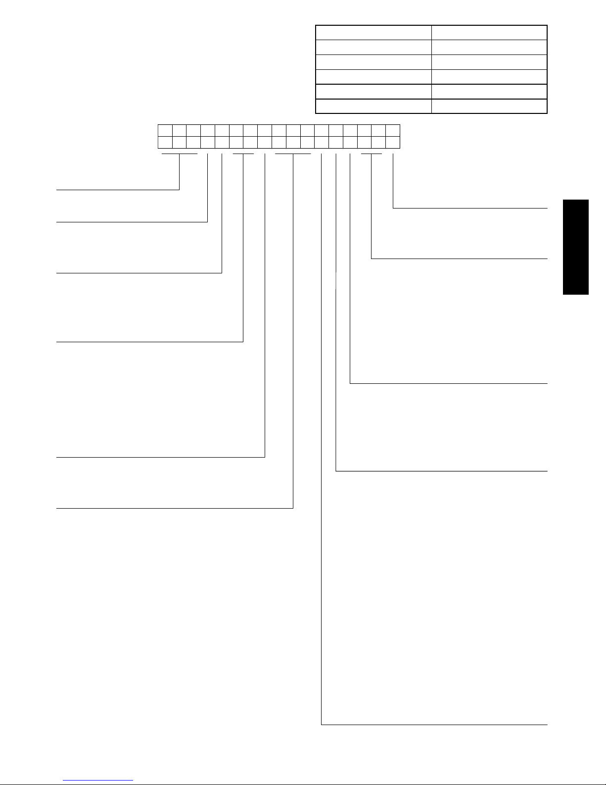
Position:
Example:
Unit Type
580 - Gas Heat RTU
Model
J - Puron
Voltage
E = 460-3-60
P = 208/230-3-60
T = 575-3-60
Cooling Tons (Vertical Air Flow Models Only)
17 = 15 tons
20 = 17.5 tons
24 = 20 tons
28 = 25 tons
30 = 27.5 tons
Refrig. System/Gas Heat Options
D = Two stage compressor with Aluminum gas heat
exchanger
F = Two stage compressor with Stainless Steel gas heat
exchanger
K = Two Stage Cooling with Aluminum gas heat exchanger
and Perfect Humidity™ (only available on 17-28 sizes
with RTPF coil models)
M = Two Stage Cooling with Stainless Steel gas heat
exchanger and Perfect Humidity™ (only available on
17-28 sizes with RTPF coil models)
Heat Level Input
220 = 220,000
310 = 310,000
400 = 400,000
®
(R-410A) Refrigerant
1234567891011 12 13 14 15 16 17
580JE1 7D310G1A0AA
Fig. 1 -- 580J MRT Vertical Airflow Units Model Number Nomenclature (Example)
Packaging & 2-Speed Indoor Fan Motor
A = Standard Packaging
D = Standard Packaging & 2-speed indoor
fan motor
Factory Installed Options
0A = None
NOTE: See the 580J 15 to 27.5 ton Price Pages for
a complete list of factory installed options.
Outdoor Air Options
A = None
B = Temperature Economizer w/ Barometric Relief
D = Temperature Economizer w/ PE (cent)
H =
Enthalpy
J =
P = Manual Outdoor Air Damper
Q = 2 Position Damper
U =
V =
W =
X =
Indoor Fan Options (Vertical Air Flow Models Only)
1 = Standard Static/Vertical Supply, Return Air Flow
2 = Medium Static/Vertical Supply, Return Air Flow
3 = High Static/Vertical Supply, Return Air Flow
B =
Medium Static High Efficiency Motor/Vertical Supply,
Return Air Flow
C = High Static High Efficiency Motor/Vertical Supply,
Return Air Flow
Novation Coil Only (Outdoor - Indoor - Hail Guard)
G = Al/Al - Al/Cu
H = Al/Al - Cu/Cu
J = Al/Al - E-coat Al/Cu
K = E-coat Al/Al - Al/Cu
L = E-coat Al/Al - E-coat Al/Cu
T = Al/Al - Al/Cu — Louvered Hail Guards
U = Al/Al - Cu/Cu — Louvered Hail Guards
V = Al/Al - E-coat Al/Cu — Louvered Hail Guards
W = E-coat Al/Al - Al/Cu — Louvered Hail Guards
X = E-coat Al/Al - E-coat Al/Cu — Louvered Hail Guards
Round Tube Plate Fin (RTPF) Coil Options
(Outdoor - Indoor - Hail Guard)
A = Al/Cu - Al/Cu
B = Precoat Al/Cu - Al/Cu
C = E-coat Al/Cu - Al/Cu
D = E-coat Al/Cu - E-coat Al/Cu
E = Cu/Cu - Al/Cu
F = Cu/Cu - Cu/Cu
M = Al/Cu - Al/Cu — Louvered Hail Guards
N = Precoat Al/Cu - Al/Cu — Louvered Hail Guards
P = E-coat Al/Cu - Al/Cu — Louvered Hail Guards
Q = E-coat Al/Cu - E-coat Al/Cu — Louvered Hail Guards
R = Cu/Cu - Al/Cu — Louvered Hail Guards
S = Cu/Cu - Cu/Cu — Louvered Hail Guards
Economizer w/ Barometric Relief
Enthalpy
Economizer w/ PE (cent)
Temp Ultra Low Leak Economizer w/ Baro Relief
Temp Ultra Low Leak Economizer
Enthalpy Ultra Low Leak Economizer w/ Baro Relief
Enthalpy Ultra Low Leak Economizer
w/ PE (cent)
w/ PE (cent)
580J--17--30--V
C13775
3
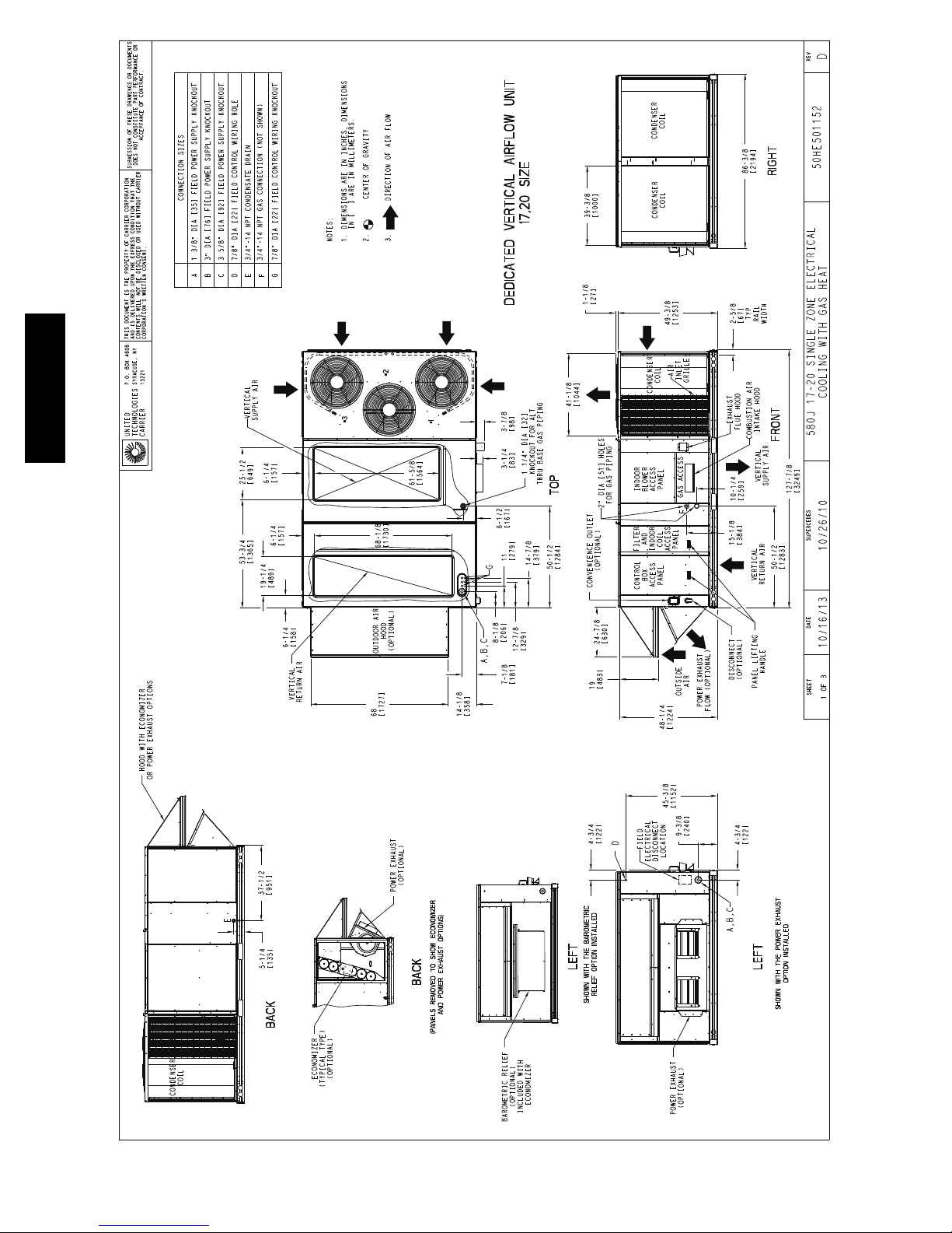
580J--17--30--V
Fig. 2 -- Unit Dimensional Drawing – 17 and 20 Size Unit
C13745
4

580J--17--30--V
Fig. 2 -- Unit Dimensional Drawing – 17 and 20 Size Unit (cont.)
C13747
5
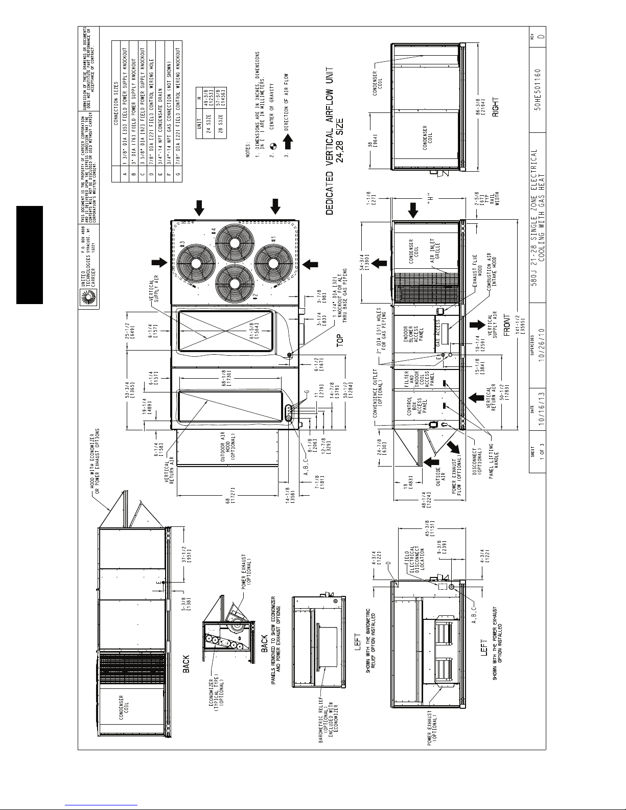
580J--17--30--V
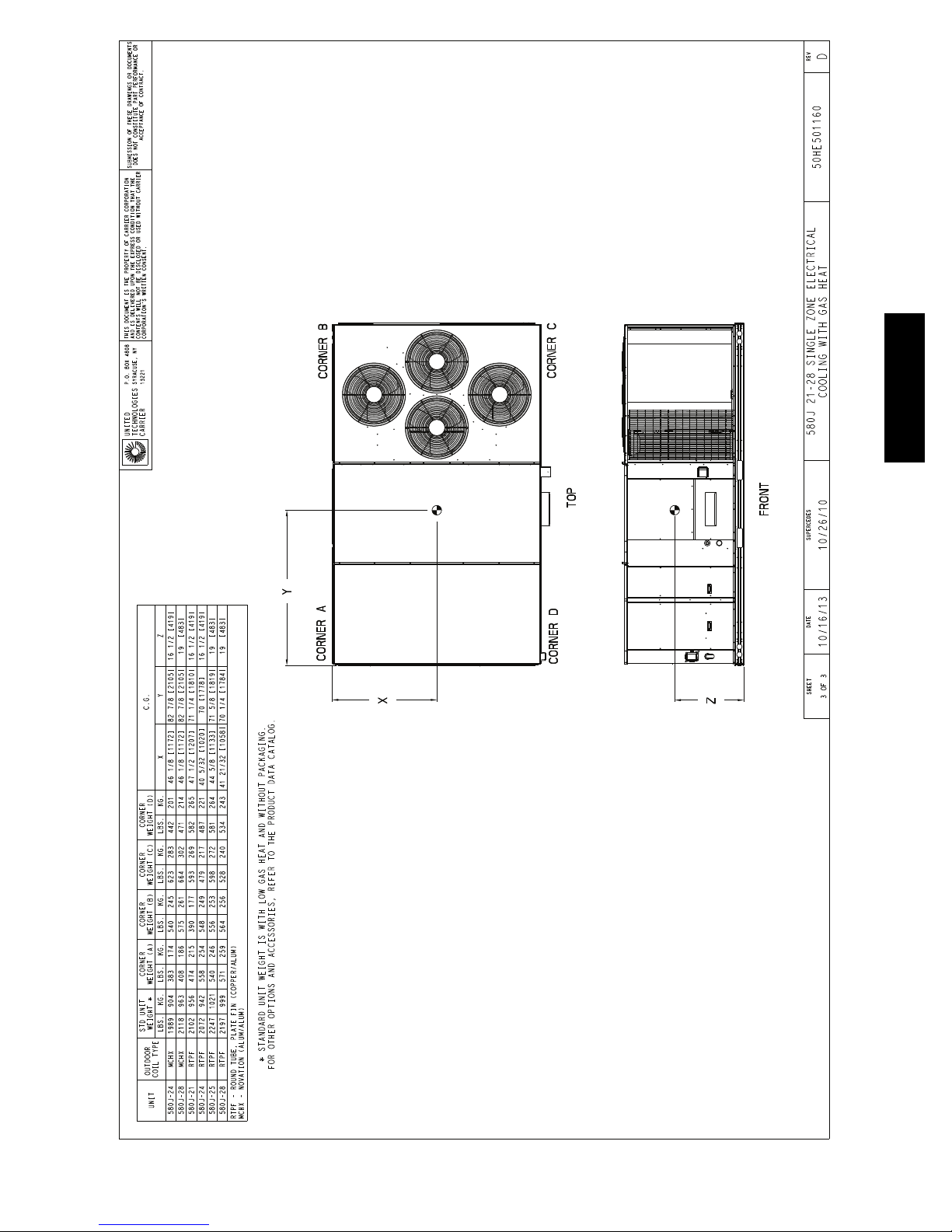
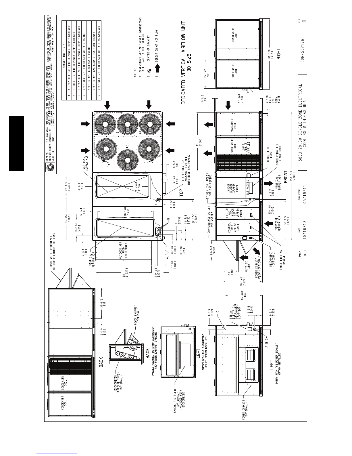
Fig. 3 -- Unit Dimensional Drawing – 24 and 28 Size Units
C13751
6
580J--17--30--V
Fig. 3 -- Unit Dimensional Drawing – 24 and 28 Size Units (cont.)
C13753
7
580J--17--30--V
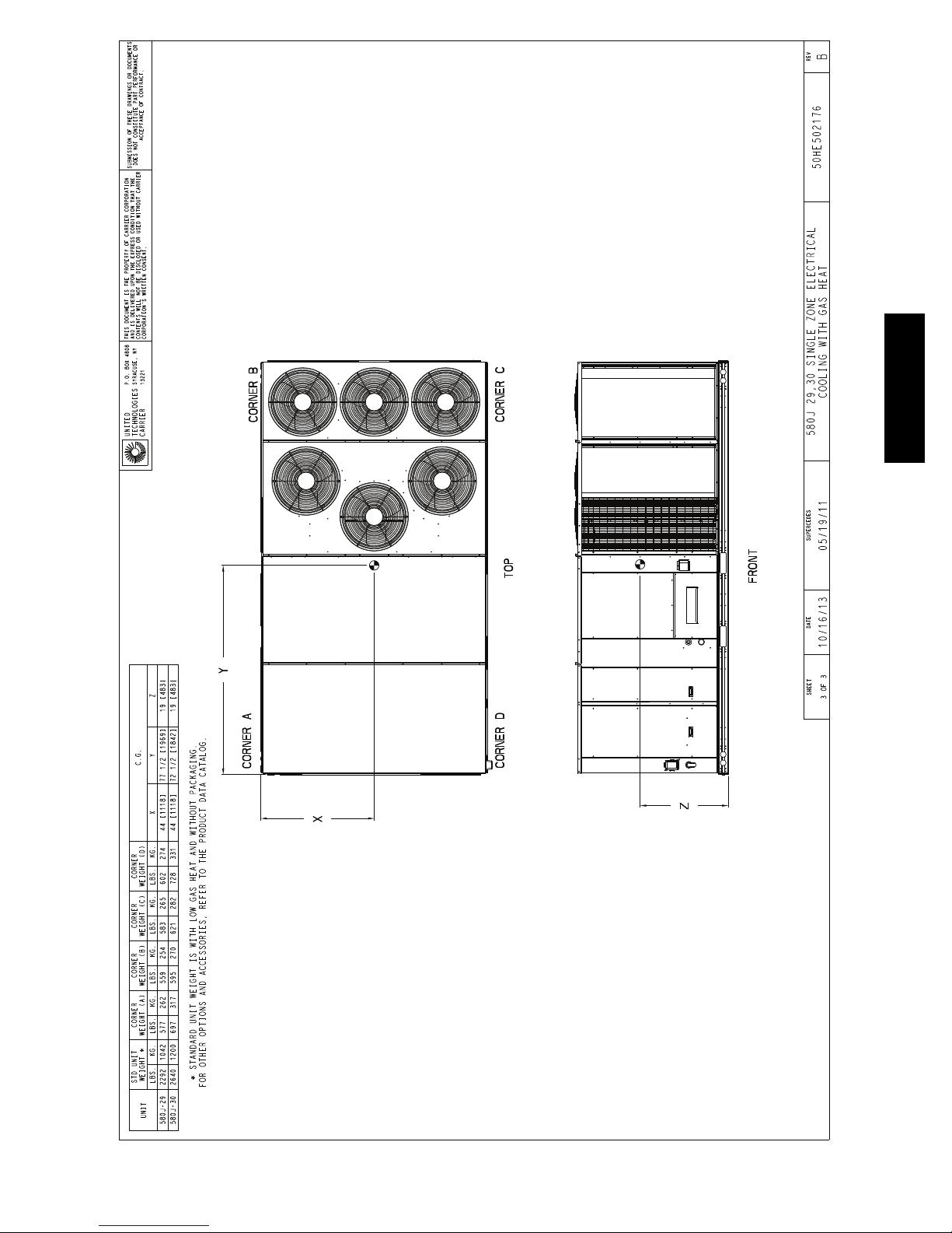
Fig. 4 -- Unit Dimensional Drawing – 30 Size Units
C13757
8
580J--17--30--V
Fig. 4 -- Unit Dimensional Drawing – 30 Size Units (cont.)
C13759
9

INSTALLATION
Jobsite Survey
Complete the following checks before installation.
1. Consult local building codes and the NEC (National
Electrical Code) ANSI/NFPA 70 for special installation requirements.
2. Determine unit location (from project plans) or select
unit location.
3. Check for possible overhead obstructions which may
interfere with unit lifting or rigging.
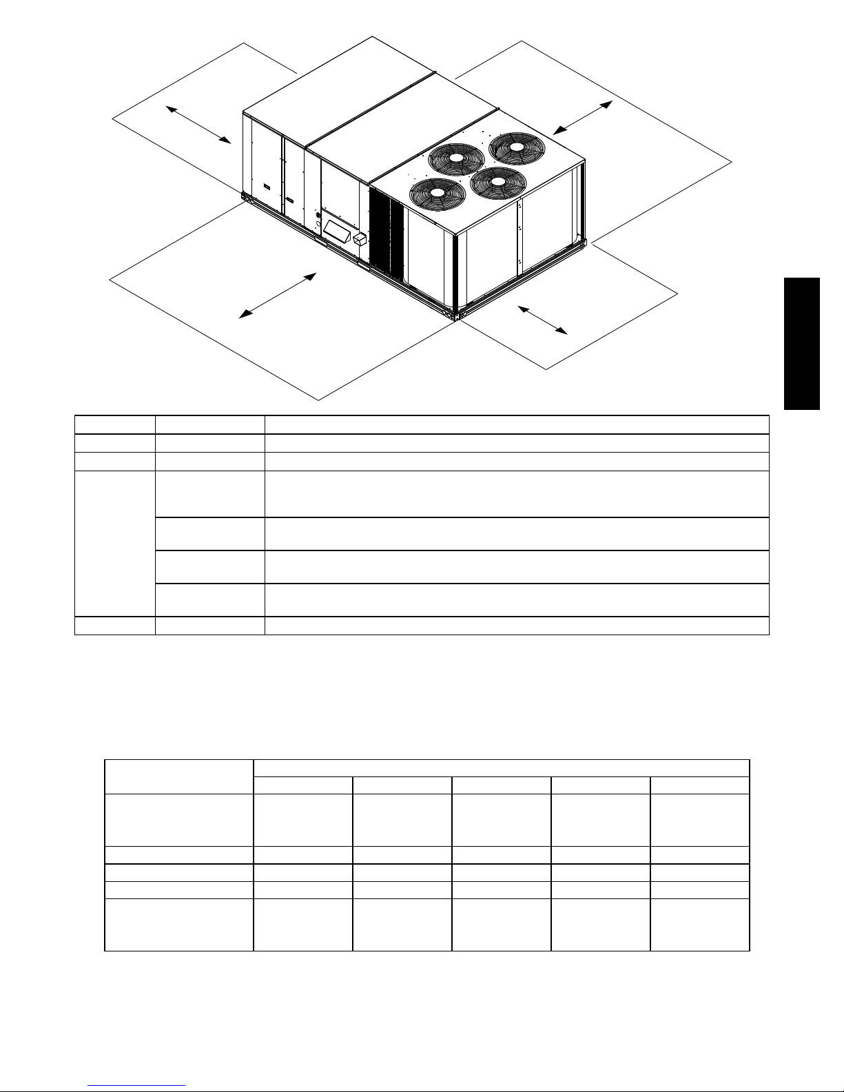
Step 1 — Plan for Unit Location
Select a location for the unit and its support system (curb
or other) that provides for the minimum clearances
required for safety. This includes the clearance to
combustible surfaces, unit performance and service access
below, around and above unit as specified in unit
drawings. See Fig. 5.
NOTE: Consider also the effect of adjacent units.
Be sure that the unit is installed such that snow will not
580J--17--30--V
block the combustion intake or flute outlet.
Unit may be installed directly on wood flooring or on
Class A, B, or C roof--covering material when roof curb is
used.
Do not install unit in an indoor location. Do not locate air
inlets near exhaust vents or other sources of contaminated
air. For proper unit operation, adequate combustion and
ventilation air must be provided in accordance with
Section 5.3 (Air for Combustion and Ventilation) of the
National Fuel Gas Code, ANSI Z223.1 (American
National Standards Institute) and NFPA (National Fire
Protection Association) 54 TIA--54--84--1. In Canada,
installation must be in accordance with the CAN1--B149
installation codes for gas burning appliances.
Although unit is weatherproof, avoid locations that permit
water from higher level runoff and overhangs to fall onto
the unit.
Locate mechanical draft system flue assembly at least 4 ft
(1.2 m) from any opening through which combustion
products could enter the building, and at least 4 ft (1.2 m)
from any adjacent building (or per local code). Locate the
flue assembly at least 10 ft (3.05 m) from an adjacent
unit’s fresh air intake hood if within 3 ft (0.91 m) of same
elevation (or per local code). When unit is located
adjacent to public walkways, flue assembly must be at
least 7 ft (2.1 m) above grade.
Select a unit mounting system that provides adequate
height to allow installation of condensate trap per
requirements. Refer to Step 11 — Install External
Condensate Trap and Line – for required trap dimensions.
Roof Mount —
Check building codes for weight distribution
requirements. Unit operating weight is shown in Table 1.
Step 2 — Plan for Sequence of Unit Installation
The support method used for this unit will dictate different
sequences for the steps of unit installation. For example, on
curb--mounted units, some accessories must be installed on
the unit before the unit is placed on the curb. Review the
following for recommended sequences for installation steps.
Curb--mounted installation —
Install curb
Install field--fabricated ductwork inside curb
Install thru--base service connection fittings (affects
curb and unit)
Rig and place unit
Remove top skid
Install outside air hood
Install smoke detector tube
Install combustion air hood
Install flue hood
Install gas piping
Install condensate line trap and piping
Make electrical connections
Install other accessories
Pad--mounted installation —
Prepare pad and unit supports
Rig and place unit
Remove duct covers and top skid
Install smoke detector return air sensor tube
Install field--fabricated ductwork at unit duct openings
Install outside air hood
Install combustion air hood
Install flue hood
Install gas piping
Install condensate line trap and piping
Make electrical connections
Install other accessories
Frame--mounted installation —
Frame--mounted applications generally follow the
sequence for a curb installation. Adapt as required to
suit specific installation plan.
Step 3 — Inspect unit
Inspect unit for transportation damage. File any claim
with transportation agency.
Confirm before installation of unit that voltage, amperage
and circuit protection requirements listed on unit data
plate agree with power supply provided.
On units with hinged panel option, check to be sure all
latches are tight and in closed position.
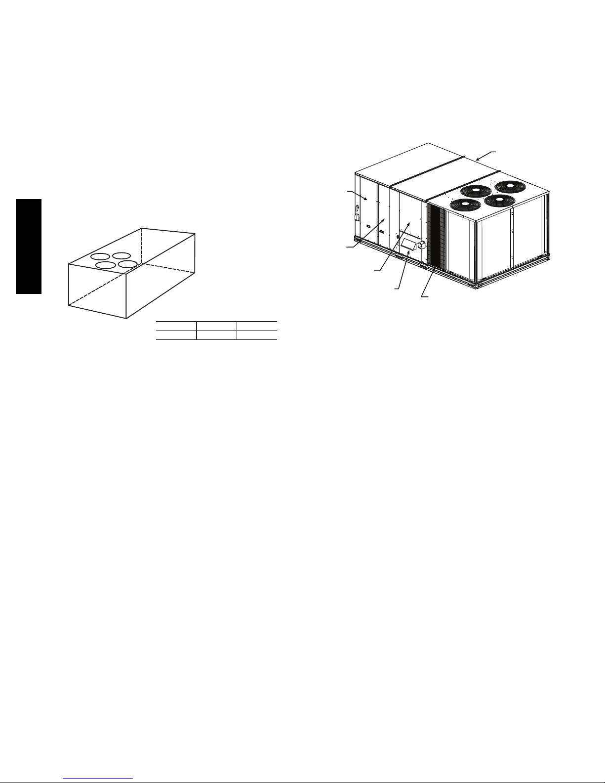
Locate the carton containing the outside air hood parts; see
Figs. 7 and 13. Do not remove carton until unit has been
rigged and located in final position.
10
C
D
B
LOCATION DIMENSION CONDITION
A 36---in (914 mm) • Recommended clearance for air flow and service
B 42--- in (1067 mm) • Recommended clearance for air flow and service
• No Convenience Outlet
18---in (457 mm)
36---in (914 mm)
C
42---in (1067 mm)
96---in (2438 mm)
D 42 --- in (1067 mm) • Recommended clearance for service.
NOTE: Unit not designed to have overhead obstruction. Contact Application Engineering for guidance on any application planning
overhead obstruction or for vertical clearances.
•NoEconomizer
• No field installed disconnect on economizer hood side (Factory-- -installed disconnect installed).
• Convenience Outlet installed.
• Vertical surface behind servicer is electrically non---conductive (e.g.: wood, fiberglass).
• Convenience Outlet installed.
• Vertical surface behind servicer is electrically conductive (e.g.: metal, masonry).
• Economizer and/or Power Exhaust installed.
• Check for sources of flue products with 10 feet (3 meters) of economizer fresh air intake.
A
Fig. 5 -- Service Clearance Dimensional Drawing
580J--17--30--V
C12384
580J*
Base Unit
Novation™ Coil 1824 (829) 1839 (836) 1989 (904) 2118 (963) N/A
RTPF Coil 1907 (867) 1922 (874) 2072 (942) 2197 (999) 2640 (1200)
Economizer 246 (112) 246 (112) 246 (112) 246 (112) 246 (112)
Powered Outlet 35 (16) 35 (16) 35 (16) 35 (16) 35 (16)
Perfect Humidity™ System 110 (50) 110 (50) 120 (54) 120 (54) N/A
Curb
14--- in/356 mm 240 (109) 240 (109) 255 (116) 255 (116) 255 (116)
24--- in/610 mm 340 (154) 340 (154) 355 (161) 355 (161) 355 (161)
Table 1 – Operating Weights
UNIT LB (KG)
17 20 24 28 30
11
Step 4 — Provide Unit Support
A
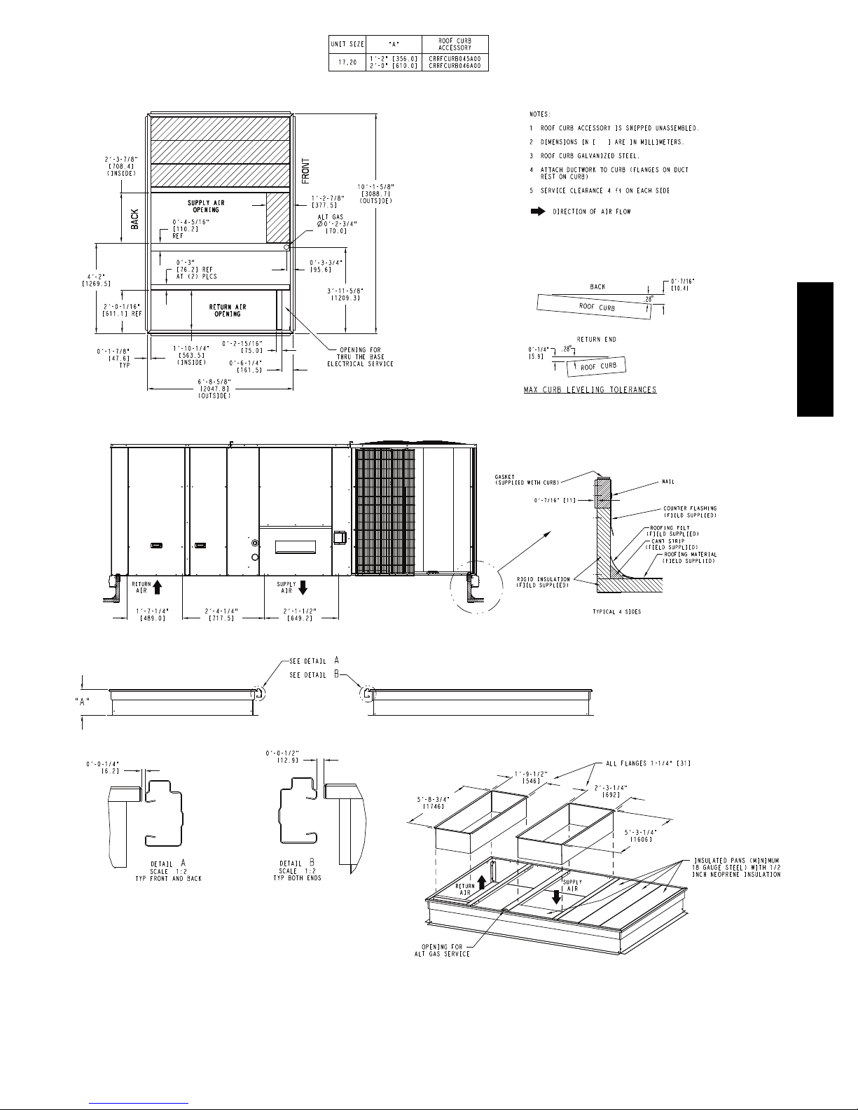
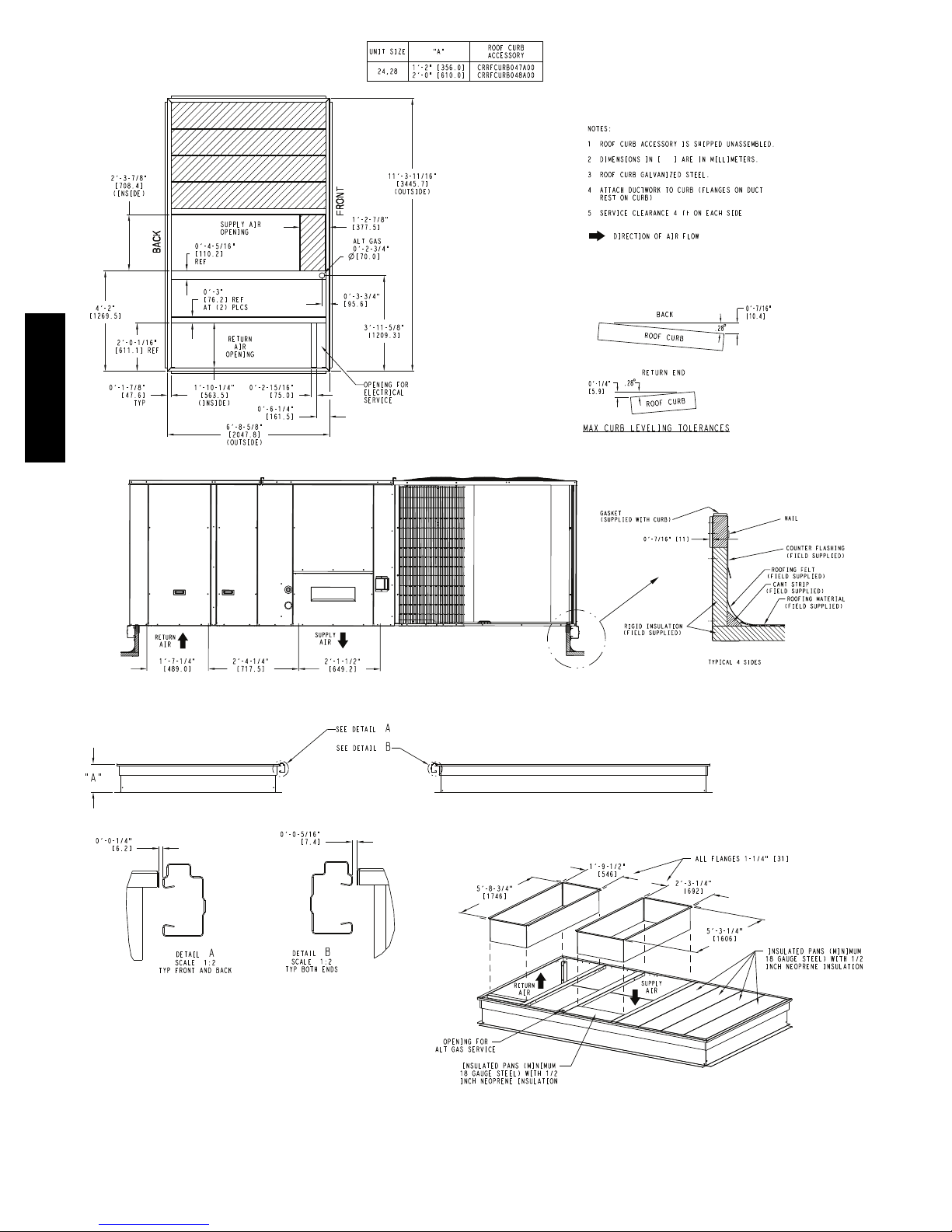
Roof Curb Mount —
Accessory roof curb details and dimensions are shown in
Figs. 8, 9 and 10. Assemble and install accessory roof
curb in accordance with instructions shipped with the
curb.
NOTE: The gasketing of the unit to the roof curb is
critical for a watertight seal. Install gasket supplied with
the roof curb as shown in Figs. 8, 9 and 10. Improperly
applied gasket can also result in air leaks and poor unit
performance.
Curb should be level. This is necessary for unit drain to
function properly. Unit leveling tolerances are show in
Fig. 6. Refer to Accessory Roof Curb Installation
Instructions for additional information as required.
580J--17--30--V
A
B
0.25” (6)
Fig. 6 -- Unit Leveling Tolerances
Install insulation, cant strips, roofing felt, and counter
flashing as shown. Ductwork must be attached to curb and
not to the unit. Thru--the--base power connection must be
installed before the unit is set on the roof curb. If
C
MAXIMUM ALLOWABLE
DIFFERENCE IN. (MM)
A-B
B-C
0.5” (12)
A-C
0.5” (12)
C10628
field--installed thru--the--roof curb gas connections are
desired remove knockout in basepan located in the gas
section, see Fig. 7 for location. Gas connections and
power connections to the unit must be field installed after
the unit is installed on the roof curb.
If electric and control wiring is to be routed through the
basepan remove knockouts in basepan located in control
box area, see Fig. 2, 3 or 4 for basepan knockout
locations. Attach the service connections to the basepan.
Hood Carton Location
(rear access panel)
Control Box
ccess Panel
Filter and
Indoor Coil
Access Panel
Indoor Blower
Access Panel
Gas Heat
Access Panel
Compressor
(each side)
C11154
Fig. 7 -- Typical Access Panel and Compressor Locations
Alternate Unit Support (In Lieu of Curb Mount) —
A non--combustible sleeper rail can be used in the unit
curb support area. If sleeper rails cannot be used, support
the long sides of the unit with a minimum of 4 equally
spaced 4--in. x 4--in. (102 mm x 102 mm) pads on each
side. Locate pads so that they support the rails. Make sure
to avoid the fork openings.
12
580J--17--30--V
Fig. 8 -- Roof Curb Details – 17 and 20 Size Units
C09052
13
580J--17--30--V
Fig. 9 -- Roof Curb Details – 24 and 28 Size Units
C09100
14
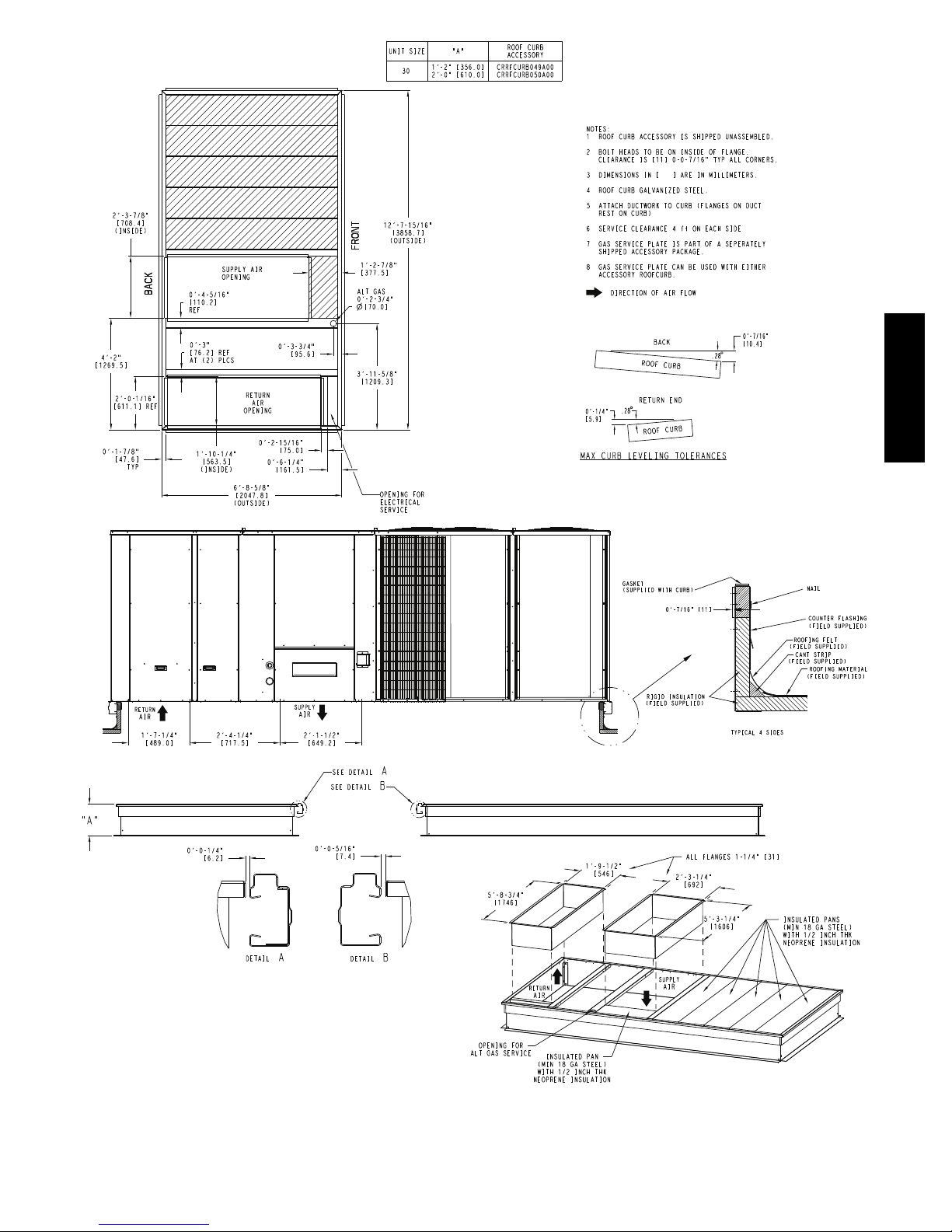
580J--17--30--V
C11224
Fig. 10 -- Roof Curb Details – 30 Size Unit
15
Step 5 — Field Fabricate Ductwork
Cabinet return-air static pressure (a negative condition)
shall not exceed 0.5 in. wg (87 Pa) with economizer or
without economizer.
For vertical ducted applications, secure all ducts to roof curb
and building structure. Do not connect ductwork to unit.
Fabricate supply ductwork so that the cross sectional
dimensions are equal to or greater than the unit supply
duct opening dimensions for the first 18 in. (458 mm) of
duct length from the unit basepan.
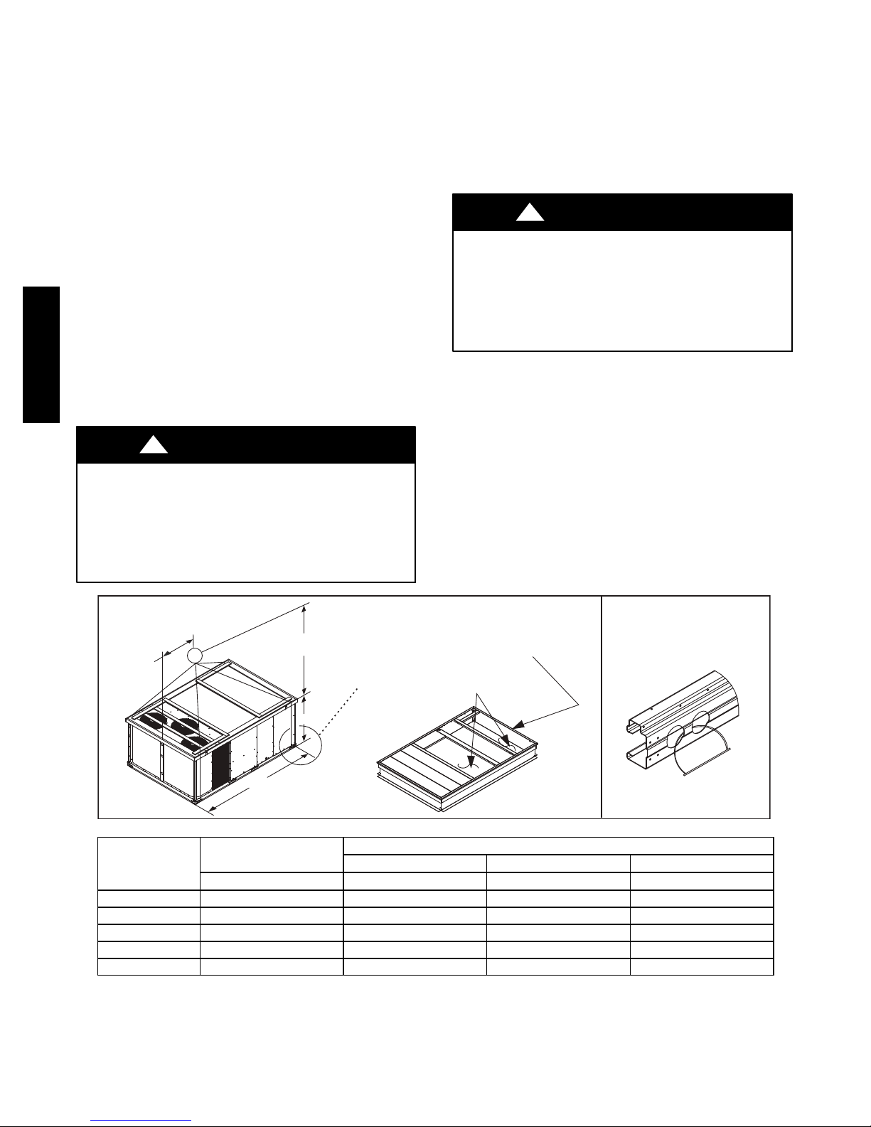
Step 6 — Rig and Place Unit
Keep unit upright and do not drop. Spreader bars are not
required if top crating is left on unit. Rollers may be used
to move unit across a roof. Level by using unit frame as a
reference. See Table 1 (on page 11) and Fig. 11 for
additional information.
Lifting holes are provided in base rails as shown in Fig.
11. Refer to rigging instructions on unit.
!
CAUTION
Insulate and weatherproof all external ductwork, joints,
and roof openings with counter flashing and mastic in
accordance with applicable codes.
Ducts passing through unconditioned spaces must be
insulated and covered with a vapor barrier.
If a plenum return is used on a vertical unit, the return
should be ducted through the roof deck to comply with
applicable fire codes.
580J--17--30--V
A minimum clearance is not required around ductwork.
!
CAUTION
PROPERTY DAMAGE HAZARD
Failure to follow this caution may result in damage
to roofing materials.
Membrane roofs can be cut by sharp sheet metal
edges. Be careful when placing any sheet metal parts
on such roof.
"914-1371"
(36"-54")
"B"
SEE DETAIL A
UNIT DAMAGE HAZARD
Failure to follow this caution may result in
equipment damage.
All panels must be in place when rigging. Unit is not
designed for handling by fork truck when packaging
is removed.
Before setting the unit onto the curb, recheck gasketing on
curb.
PLACE ALL SEAL STRIP
IN PLACE BEFORE PLACING
UNIT ON ROOF CURB.
DUCT END
DETAIL A
"A"
UNIT
580J*17 2355 1068 127.8 3249 58.7 1491 52.3 1328
580J*20 2370 1075 127.8 3249 58.7 1491 52.3 1328
580J*24 2516 1141 141.5 3595 71.5 1816 52.3 1328
580J*28 2652 1203 141.5 3595 71.5 1816 60.3 1532
580J*30 2976 1353 157.8 4007 80.3 2040 60.3 1532
NOTES:
1. Dimensions in ( ) are in inches.
2. Hook rigging shackles through holes in base rail, as shown in detail “A.” Holes in base rails are centered around the unit center of gravity.
Use wooden top to p revent rigging straps from damaging unit.
MAX WEIGHT
LB KG IN MM IN MM IN MM
"C"
C09107
DIMENSIONS
A B C
Fig. 11 -- Rigging Details
16
 Loading...