

Bryant 580J***D series Installation Instructions Manual
580J***D
SINGLE PACKAGE ROOFTOP
GAS HEATING/ELECTRIC COOLING UNIT
WITH NOVATIONt COIL
SIZES 17, 20, 24, 28 WITH PURONR(R--410A) REFRIGERANT
Installation Instructions
NOTE: Read the entire instruction manual before starting
the installation
TABLE OF CONTENTS
SAFETY CONSIDERATIONS 1....................
INSTALLATION 6...............................
Step 1 -- Plan for Unit Location 6..................
Step 2 -- Plan for Sequence of Unit Installation 7......
Step 3 -- Inspect Unit 7...........................
Step 4 -- Provide Unit Support 7...................
Step 5 -- Field Fabricate Ductwork 11...............
Step 6 -- Rig and Place Unit 11....................
Step 7 -- Duct Connection 12.....................
Step 8 -- Install Outside Air Hood 12...............
Step 9 -- Install Flue Hood and Combustion Air Hood 13
Step 10 -- Install Gas Piping 13....................
Step 11 -- Install External Condensate Trap and Line 16
Step 12 -- Make Electrical Connections 16...........
Step 13 -- Adjust Factory--Installed Options 32........
Step 14 -- Install Accessories 32...................
SAFETY CONSIDERATIONS
Improper installation, adjustment, alteration, service,
maintenance, or use can cause explosion, fire, electrical
shock or other conditions which may cause personal
injury or property damage. Consult a qualified installer,
service agency, or your distributor or branch for
information or assistance. The qualified installer or
agency must use factory--authorized kits or accessories
when modifying this product. Refer to the individual
instructions packaged with the kits or accessories when
installing.
Follow all safety codes. Wear safety glasses and work
gloves. Use quenching cloths for brazing operations and
have a fire extinguisher available. Read these instructions
thoroughly and follow all warnings or cautions attached to
the unit. Consult local building codes and appropriate
national electrical codes (in USA, ANSI/NFPA70,
National Electrical Code (NEC); in Canada, CSA C22.1)
for special requirements.
It is important to recognize safety information. This is the
safety--alert symbol
unit and in instructions or manuals, be alert to the
potential for personal injury.
Understand the signal words DANGER, WARNING,
CAUTION, and NOTE. These words are used with the
safety--alert symbol. DANGER identifies the most serious
hazards which will result in severe personal injury or
death. WARNING signifies hazards which could result in
personal injury or death. CAUTION is used to identify
unsafe practices, which may result in minor personal
injury or product and property damage. NOTE is used to
highlight suggestions which will result in enhanced
installation, reliability, or operation.
. When you see this symbol on the
!
WARNING
FIRE, EXPLOSION HAZARD
Failure to follow this warning could result in personal
injury or death.
Disconnect gas piping from unit when leak testing at
pressure greater than 0.5 psig (3450 Pa). Pressures
greater than 0.5 psig (3450 Pa) will cause gas valve
damage resulting in hazardous condition. If gas valve
is subjected to pressure greater than 0.5 psig (3450
Pa), it must be replaced before use. When pressure
testing field--supplied gas piping at pressures of 0.5
psig (3450 Pa) or less, a unit connecte d to such piping
must be isolated by closing the manual gas valve.
!
WARNING
ELECTRICAL SHOCK HAZARD
580J***D
Failure to follow this warning could cause personal
injury or death.
Before performing service or maintenance operations
on unit, always turn off main power switch to unit and
install lockout tag. Unit may have more than one
power switch.
!
WARNING
PERSONAL INJURY AND ENVIRONMENTAL
HAZARD
Failure to follow this warning could cause personal
injury or death.
Relieve pressure and recover all refrigerant before
system repair or final unit disposal.
Ware safety glasses and gloves when handling
refrigerants. Keep torches and other ignition sources
away from refrigerants and oils.
!
CAUTION
CUT HAZARD
Failure to follow this caution may result in personal
injury.
Sheet metal parts may have sharp edges or burrs. Use
care and wear appropriate protec tive clothing, safety
glasses and gl oves when handling parts and servicing
air conditioning units.
!
WARNING
UNIT OPERATION AND SAFETY HAZARD
Failure to follow this warning could cause personal
injury, death and/or equipment damage.
Puronr (R--410A) refrigerant systems operate at
higher pressures than standard R--22 systems. Do not
use R--22 service equipment or components on Puron
refrigerant equipment.
2
580J***D
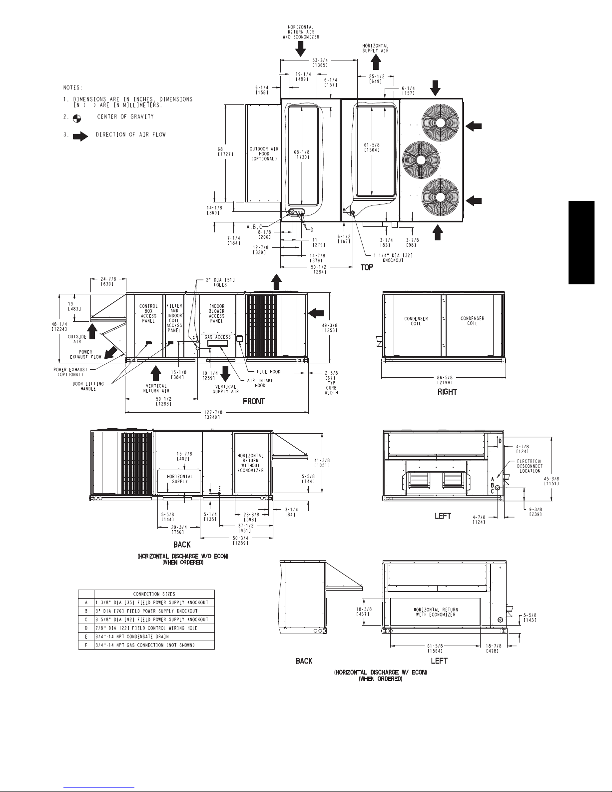
Fig. 1 -- Unit Dimensional Drawing – 17 and 20 Size Units
C09128
3

580J***D
C09129
Fig. 1 -- Unit Dimensional Drawing – 17 and 20 Size Units (cont.)
4
580J***D
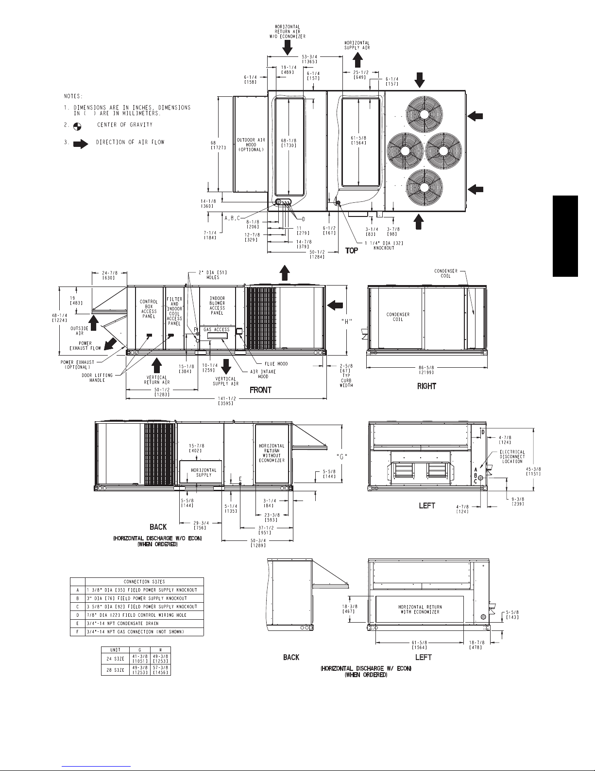
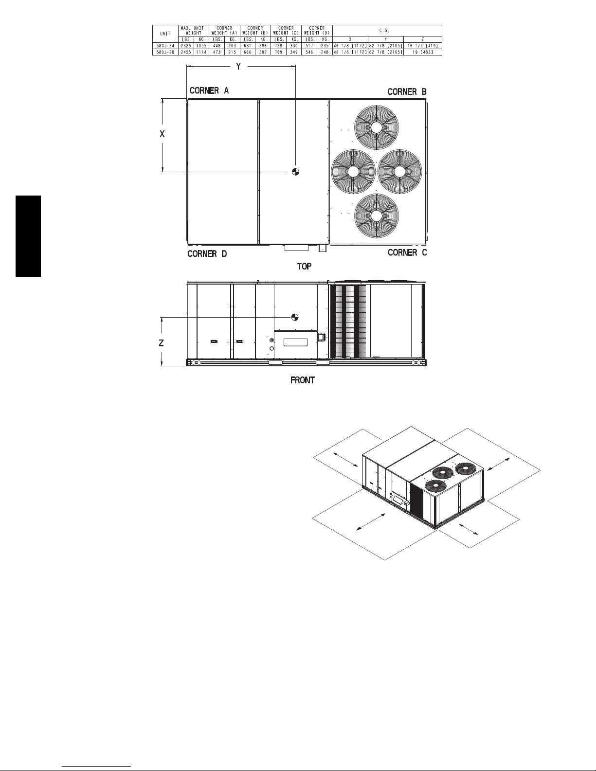
Fig. 2 -- Unit Dimensional Drawing – 24 and 28 Size Units
C09130
5
580J***D
C09131
Fig. 2 -- Unit Dimensional Drawing – 24 and 28 Size Units (cont.)
INSTALLATION
Jobsite Survey
Complete the following checks before installation.
1. Consult local building codes and the NEC (National
Electrical Code) ANSI/NFPA 70 for special installation requirements.
2. Determine unit location (from project pl ans) or select
unit location.
3. Check for possible overhead obstructions which may
interfere with unit lifting or rigging.
Step 1 — Plan for Unit Location
Select a location for the unit and its support system (curb
or other) that provides for the minimum clearances
required for safety. This includes the clearance to
combustible surfaces, unit performance and service access
below, around and above unit as specified in unit
drawings. See Fig. 3.
NOTE: Consider also the effect of adjacent units.
Be sure that the unit is installed such that snow will not
block the combustion intake or flute outlet.
Unit may be installed directly on wood flooring or on
Class A, B, or C roof--covering material when roof curb is
used.
36” (914)
42” (1067)
42” (1067)
18” (457)
C09051
Fig. 3 -- Service Clearance Dimensional Drawing
Do not install unit in an indoor location. Do not locate air
inlets near exhaust vents or other sources of contaminated
air. For proper unit operation, ade quate combustion and
ventilation air must be provided in accordance with
Section 5.3 (Air for Combustion and Ventilation) of the
National Fuel Gas Code, ANSI Z223.1 (American
National Standards Institute) and NFPA (National Fire
Protection Association) 54 TIA-- --54----84 ----1. In Canada,
installation must be in accordance with the CAN1----B149
installation codes for gas burning appliances.
6
Although unit is weatherproof, a void locations that permit
water from higher level runoff and overhangs to fall onto
the unit.
Locate mechanical draft system flue assembly at least 4 ft
(1.2 m) from any opening through which combustion
products could enter the building, and at least 4 ft (1.2 m)
from any adjacent building (or per local code). Locate the
flue assembly at least 10 ft (3.05 m) from an adjacent
unit’s fresh air intake hood if within 3 ft (0.91 m) of same
elevation (or per local code). When unit is located
adjacent to public walkways, flue assembly must be at
least 7 ft (2.1 m) above grade.
Select a unit mounting system that provides adequate
height to allow installation of condensate trap per
requirements. Refe r to Step 11 — Install External
Condensate Trap and Line – for required trap dimensions.
Roof mount —
Check building codes for weight distribution
requirements. Unit operati ng weight is shown in Table 1.
Pad--mounted installation —
Prepare pad and unit supports
Rig and place unit
Remove duct covers and top skid
Install field--fabricated ductwork at unit duct openings
Install combustion air hood
Install flue hood
Install gas piping
Install condensate line trap and piping
Make electrical connections
Install other accessories
Frame--mounted installation —
Frame--mounted applications generally follow the
sequence for a curb installation. Adapt as required to
suit specific installation plan.
Step 3 — Inspect unit
Inspect unit for transportation damage. File any claim
with transportation agency.
580J***D
Step 2 — Plan for Sequence of Unit Installation
The support method used for this unit will dictate different
sequences for the steps of unit installation. For example,
on curb--mounted units, some accessories must be
installed on the unit before the unit is placed on the curb.
Review the following for recommended sequences for
installation steps.
Curb--mounted installation —
Install curb
Install field--fabricated ductwork inside curb
Install thru--base service connection fittings (affects
curb and unit)
Rig and place unit
Remove top skid
Install combustion air hood
Install flue hood
Install gas piping
Install condensate line trap and piping
Make electrical connections
Install other accessories
Confirm before installation of unit that voltage, amperage
and circuit protection requirements listed on unit data
plate agree with power supply provided.
Step 4 — Provide Unit Support
Roof Curb Mount —
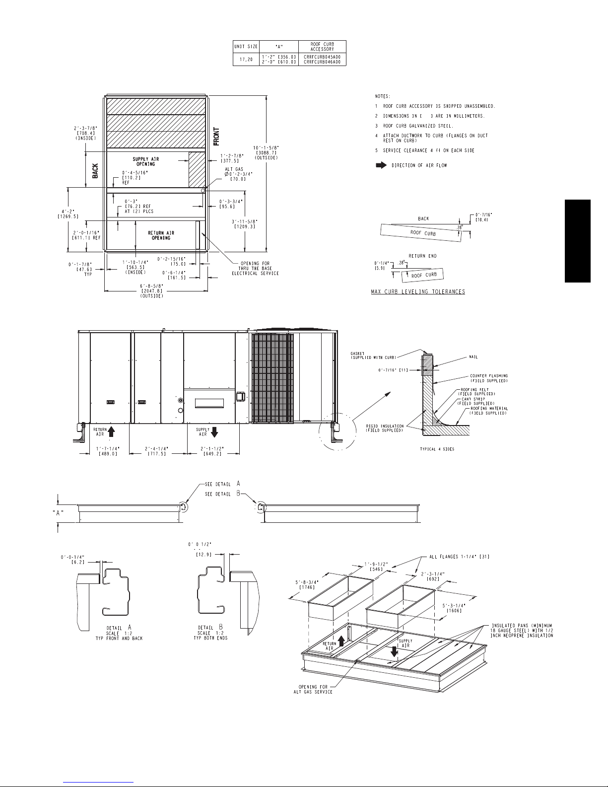
Accessory roof curb details and dimensions are shown in
Fig. 5 (size 17 and 20 units) a nd Fig. 6 (size 24 and 28
units). Assemble and install accessory roof curb in
accordance with instructions shipped with the curb.
NOTE: The gasketing of the unit to the roof curb is
critical for a watertight seal. Install gasket supplied with
the roof curb as shown in Fig. 5 and Fig. 6. Improperly
applied gasket can also result in air leaks and poor unit
performance.
Curb should be level. This is necessary for unit drain to
function properly. Unit leveling tolerances are show in
Fig. 7. Refer to Accessory Roof Curb Installation
Instructions for additional informati on as required.
580J***D UNITS LB (KG)
Component 17D 20D 24D 28D
Base Unit 1824 (828) 1839 (835) 1989 (903) 2118 (961)
Economizer 245 (111) 245 (111) 245 (111) 245 (111)
Powered Outlet 32 (15) 32 (15) 32 (15) 32 (15)
Curb
14--- in/356 mm 243 (111) 243 (111) 273 (124) 273 (124)
24--- in/610 mm 315 (143) 315 (143) 350 (159) 350 (159)
Table 1 – Operating Weights
7
Install insulation, cant strips, roofing felt, and counter
A
flashing as shown. Ductwork must be attached to curb and
not to the unit. Thru--t he--base power connection must be
installed before the unit is set on the roof curb. If
field--installed thru--the--roof curb ga s connections are
desired remove knockout in basepan located in the gas
section, see Fig. 4 for location. Gas connections and
power connections to the unit must be field installed after
the unit is installed on the roof curb.
If electric and control wiring is to be routed through the
basepan remove knockouts in basepan located in control
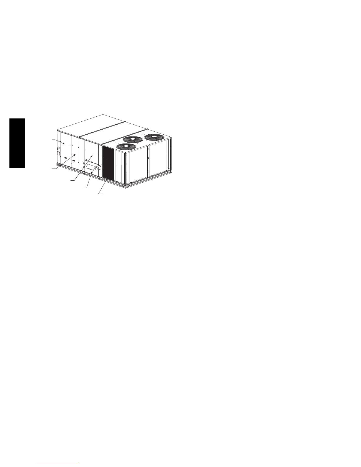
box area, see Fig. 4 for location. Attach the service
connections to the basepans.
Control Box
ccess Panel
580J***D
Filter and
Indoor Coil
Access Panel
Indoor Blower
Access Panel
Gas
Access
Panel
Compressor
(each side)
Fig. 4 -- Typica l Access Panel and Comp ressor Locatio n s
Slab Mount (Horizontal Units Only) —
Provide a level concrete slab that extends a minimum of
6 in. (150 mm) beyond unit cabinet. Install a gravel apron
in front of condenser coil air inlet to prevent grass and
foliage from obstructing airflow.
NOTE: Horizontal units may be installed on a roof curb
if required.
Alternate Unit Support (In Lieu of Curb or Slab
Mount) —
A non--combustible sleeper rail can be used in the unit
curb support area. If sleeper rails cannot be used, support
the long sides of the unit with a minimum of 4 equally
spaced 4--in. x 4-- in. (102 mm x 102 mm) pads on each
side. Locate pads so that they support the rails. Make sure
to avoid the fork openings.
C09078
8
580J***D
Fig. 5 -- Roof Curb Details – 17 and 20 Size Units
C09052
9
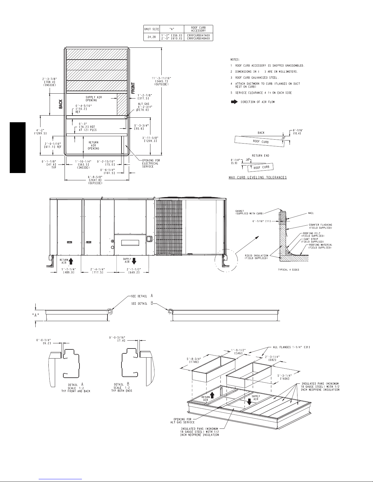
580J***D
Fig. 6 -- Roof Curb Details – 24 and 28 Size Units
C09100
10
 Loading...