

Bryant 580J*04A, 580J*04B, 580J*05C, 580J*06A, 580J*04C Installation Instructions Manual
...
LEGACY™ LINE
580J
SINGLE PACKAGE ROOFTOP WITH
GAS HEAT/ELECTRIC COOLING
SIZES 04, 05, 06 & 07
Installation Instructions
580J 07 units for installation in the United States contain use of a 2-Speed Indoor Fan Motor System. This
complies with the U.S. Department of Energy (DOE) efficiency standard of 2018.
580J 07 units for installation outside the United States may or may not contain use of the 2-Speed Indoor
Fan Motor System as they are not required to comply with the U.S. Department of Energy (DOE) efficiency
standard of 2018.
For specific details on operation of the 2-Speed Indoor Fan Motor System refer to the Variable Frequency
Drive (VFD) Factory-Installed Option 2-Speed Motor Control Installation, Setup, and Troubleshooting
manual.
TABLE OF CONTENTS
Page
GENERAL . . . . . . . . . . . . . . . . . . . . . . . . . . . . . . . . . . . . . . . 2
SAFETY CONSIDERATIONS . . . . . . . . . . . . . . . . . . . . . 2-6
INSTALLATION . . . . . . . . . . . . . . . . . . . . . . . . . . . . . . . 6-48
Job-Site Survey . . . . . . . . . . . . . . . . . . . . . . . . . . . . . . . . . . 6
Step 1 — Plan for Unit Location. . . . . . . . . . . . . . . . . . . . . 6
Roof Mount . . . . . . . . . . . . . . . . . . . . . . . . . . . . . . . . . . . 7
Step 2 — Plan for Sequence of Unit Installation. . . . . . . . . . . . 7
Curb-mounted Installation . . . . . . . . . . . . . . . . . . . . . . . . 7
Pad-mounted Installation. . . . . . . . . . . . . . . . . . . . . . . . . 7
Frame-mounted Installation. . . . . . . . . . . . . . . . . . . . . . . 7
Step 3 — Inspect Unit . . . . . . . . . . . . . . . . . . . . . . . . . . . . . 7
Step 4 — Provide Unit Support. . . . . . . . . . . . . . . . . . . . . . 7
Roof Curb Mount. . . . . . . . . . . . . . . . . . . . . . . . . . . . . . . 7
Slab Mount (Horizontal Units Only) . . . . . . . . . . . . . . . . 7
Alternate Unit Support (In Lieu Of Curb or Slab
Mount) . . . . . . . . . . . . . . . . . . . . . . . . . . . . . . . . . . . 7
Step 5 — Field Fabricate Ductwork . . . . . . . . . . . . . . . . . . 9
Step 6 — Rig and Place Unit. . . . . . . . . . . . . . . . . . . . . . . .9
Positioning on Curb . . . . . . . . . . . . . . . . . . . . . . . . . . . . .9
Step 7 — Convert to Horizontal and Connect
Ductwork (When Required) . . . . . . . . . . . . . . . . . . . . . 10
Step 8 — Install Outside Air Hood . . . . . . . . . . . . . . . . . . 10
Economizer And Two Position Damper Hood Package
Removal And Setup — Factory Option. . . . . . . . . . . . .10
Economizer Hood And Two-position Hood . . . . . . . . . 10
Step 9 — Install Flue Hood . . . . . . . . . . . . . . . . . . . . . . . . 11
Step 10 — Install Gas Piping . . . . . . . . . . . . . . . . . . . . . .11
Factory-option Thru-base Connections (Gas
Connections). . . . . . . . . . . . . . . . . . . . . . . . . . . . . . 12
Step 11 — Install External Condensate Trap and Line . . . 14
Step 12 — Make Electrical Connections . . . . . . . . . . . . . 14
Field Power Supply . . . . . . . . . . . . . . . . . . . . . . . . . . . 15
Units With Factory-Installed Non-Fused Disconnect . 15
Units Without Factory-Installed Non-fused Disconnect. . .16
Convenience Outlets. . . . . . . . . . . . . . . . . . . . . . . . . . . 18
Factory-Option Thru-Base Connections (Electrical
Connections) . . . . . . . . . . . . . . . . . . . . . . . . . . . . 19
Perfect Humidity™ Control Connections . . . . . . . . . . . .20
Economi$er
Economizer Module Wiring Details. . . . . . . . . . . . . . . 23
Interface Overview . . . . . . . . . . . . . . . . . . . . . . . . . . . . 24
RTU Open Control System . . . . . . . . . . . . . . . . . . . . . 36
RTU Open Control System Field Connections . . . . . . 40
RTU Open Communication Wiring Protocols . . . . . . . 43
Local Access. . . . . . . . . . . . . . . . . . . . . . . . . . . . . . . . . 44
Outdoor Air Enthalpy Control . . . . . . . . . . . . . . . . . . . 45
Smoke Detectors. . . . . . . . . . . . . . . . . . . . . . . . . . . . . . 45
Step 13 — Adjust Factory-Installed Options . . . . . . . . . . 47
Smoke Detectors. . . . . . . . . . . . . . . . . . . . . . . . . . . . . . 47
Economi$er IV Occupancy Switch . . . . . . . . . . . . . . . 47
Step 14 — Install Accessories . . . . . . . . . . . . . . . . . . . . . 47
Step 15 — Check Belt Tension . . . . . . . . . . . . . . . . . . . . 47
Belt Force — Deflection Method. . . . . . . . . . . . . . . . . 47
Belt Tension Method . . . . . . . . . . . . . . . . . . . . . . . . . . 48
Pre-Start and Start-Up . . . . . . . . . . . . . . . . . . . . . . . . . . . 48
START-UP CHECKLIST . . . . . . . . . . . . . . . . . . . CL-1, CL-2
®
X (Factory-Installed Option) . . . . . . . . . 22
Page
GENERAL
These installation instructions cover the 580J units with gas
heat and electric cooling. Units are pre-wired and pre-charged
with environmentally sound Puron
®
(R-410A) refrigerant at
the factory. See Fig. 1 for model number nomenclature. See
Fig. 2 for unit dimensions. See Fig. 3 for service clearances.
SAFETY CONSIDERATIONS
Improper installation, adjustment, alteration, service, maintenance, or use can cause explosion, fire, electrical shock or
other conditions which may cause personal injury or property
damage. Consult a qualified installer, service agency, or your
distributor or branch for information or assistance. The qualified installer or agency must use factory-authorized kits or accessories when modifying this product. Refer to the individual
instructions packaged with the kits or accessories when installing.
Follow all safety codes. Wear safety glasses and work
gloves. Use quenching cloths for brazing operations and have a
fire extinguisher available. Read these instructions thoroughly
and follow all warnings or cautions attached to the unit.
Consult local building codes and appropriate national electrical
codes (in USA, ANSI/NFPA70, National Electrical Code
(NEC); in Canada, CSA C22.1) for special requirements.
It is important to recognize safety information. This is the
safety-alert symbol. When you see this symbol on the unit and
in instructions or manuals, be alert to the potential for personal
injury.
Understand the signal words DANGER, WARNING, CAUTION, and NOTE. These words are used with the safety-alert
symbol. DANGER identifies the most serious hazards which
will result in severe personal injury or death. WARNING signifies hazards which could result in personal injury or death.
CAUTION is used to identify unsafe practices, which may result in minor personal injury or product and property damage.
NOTE is used to highlight suggestions which will result in enhanced installation, reliability, or operation.
WARNING
Failure to follow this warning could result in personal
injury or death. Disconnect gas piping from unit when leak
testing at pressure greater than 0.5 psig (3450 Pa). Pressures greater than 0.5 psig (3450 Pa) will cause gas valve
damage resulting in hazardous condition. If gas valve is
subjected to pressure greater than 0.5 psig (3450 Pa), it
must be replaced before use. When pressure testing fieldsupplied gas piping at pressures of 0.5 psig (3450 Pa) or
less, a unit connected to such piping must be isolated by
closing the manual gas valve.
WARNING
Failure to follow this warning could cause personal injury
or death. Before performing service or maintenance operations on unit, always turn off main power switch to unit and
install lock(s) and lockout tag(s). Unit may have more than
one power switch.
!
WARNING
Failure to follow this warning could cause personal injury,
death and/or equipment damage.
Puron (R-410A) refrigerant systems operate at higher pressures than standard R-22 systems. Do not use R-22 service
equipment or components on Puron refrigerant equipment.
WARNING
Failure to follow this warning could cause personal injury
or death.
Relieve pressure and recover all refrigerant before system
repair or final unit disposal.
Wear safety glasses and gloves when handling refrigerants.
Keep torches and other ignition sources away from refrigerants and oils.
CAUTION
Failure to follow this caution may result in personal injury.
Sheet metal parts may have sharp edges or burrs. Use care
and wear appropriate protective clothing, safety glasses and
gloves when handling parts and servicing air conditioning
equipment.
Rated Indoor Airflow (cfm) — Table 1 lists the rated in-
door airflow used for the AHRI efficiency rating for the units
covered in this document.
Table 1 — AHRI Efficiency — Rated Indoor Airflow
MODEL NUMBER FULL LOAD AIRFLOW (CFM)
580J*04A/B/C 1275
580J*05A/B/C 1400
580J*06A/B/C 1800
580J*07A/C/G/J 2200
2
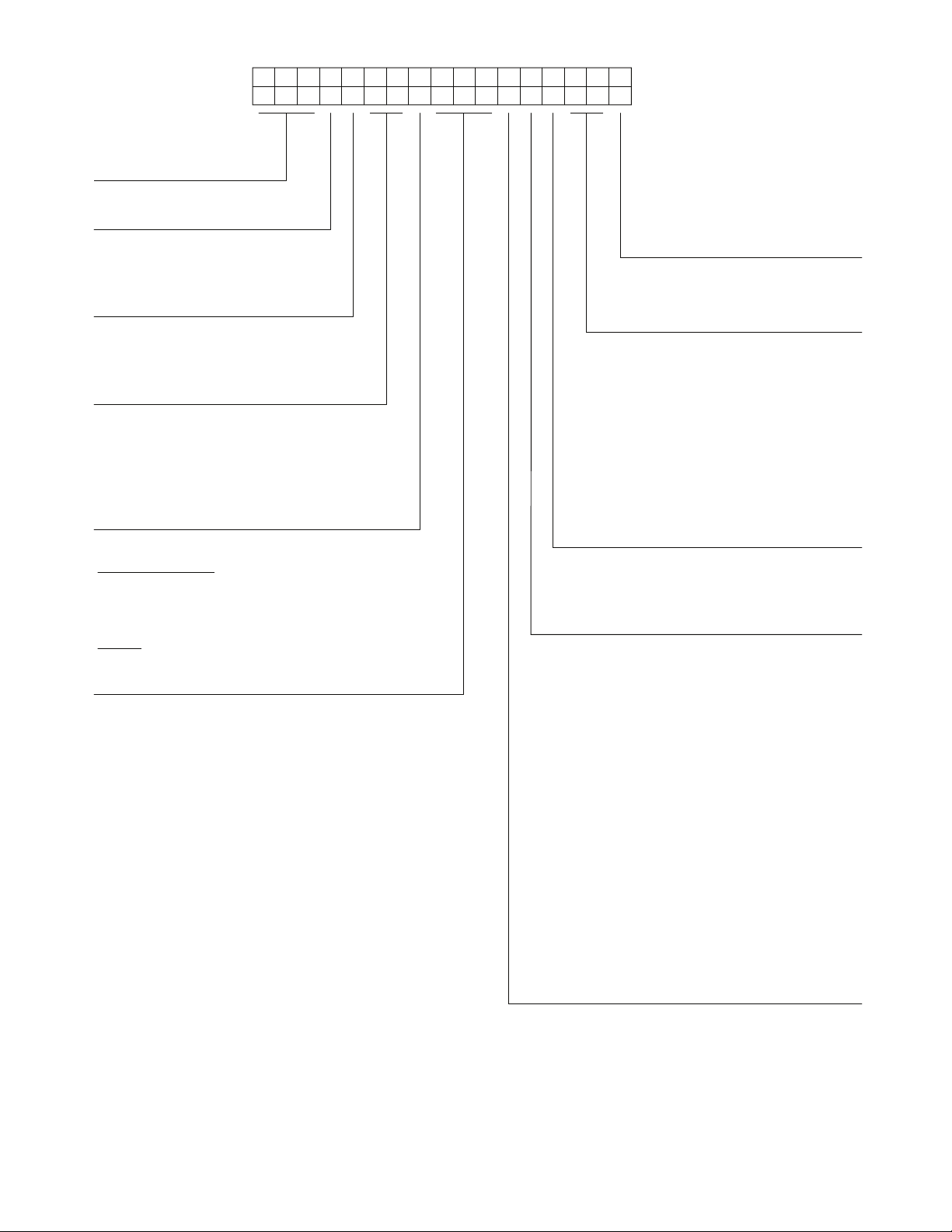
Position:
Example:
1234567891011 12 13 14 15 16 17
580JE0 6A072A1B0AA
Unit Type
580 - Gas Heat RTU
Legacy™ Series
Model
J - Puron
®
(R-410A) Refrigerant
Voltage
E = 460-3-60
J = 208/230-1-60
P = 208/230-3-60
T = 575-3-60
Cooling Tons
04 - 3 tons
05 - 4 tons
06 - 5 tons
07 - 6 tons
Refrig. System/Gas Heat Options
A = Standard One Stage cooling models/Natural Gas Heat
B = Standard One Stage cooling models/Low NO
C = Standard One Stage cooling models/Stainless Steel HX Heat
Heat
x
G = One Stage cooling models/Alum Heat Exchanger
with Perfect Humidity™ (07 models only)
J = One Stage cooling models/Stainless Steel Exchanger
with Perfect Humidity™ (07 models only)
Heat Level
Standard/Stainless Steel
072 = 72,000
115 = 115,000
125 = 125,000
150 = 150,000
Low NOx
060 = 60,000
090 = 90,000
120 = 120,000
Note: On single phase (-J voltage code) models, the
following are not available as a factory installed option:
- Coated Coils or Cu Fin Coils
- Louvered Hail Guards
- Economizer or 2 Position Damper
- Powered 115 Volt Convenience Outlet
Packaging & 2-Speed Indoor Fan Motor
A = Standard Packaging, electro mech. controls
that require W7212 EconoMi$er
®
IV
B = LTL Packaging, electro mech. controls
that require W7212 EconoMi$er IV
C = Standard Packaging, electro mech. controls
that require W7220 EconoMi$er X
F = LTL Packaging, electro mech. controls
that require W7220 EconoMi$er X
Factory Installed Options
0A = None
NOTE: See the 580J 3 to 15 ton Price Pages for a
complete list of factory installed options.
Outdoor Air Options
A = None
B = Temperature Economizer, Barometric Relief,
Standard Leak (W7212 or W7220)
E = Temperature Economizer, Barometric Relief,
Standard Leak w/CO
Enthalpy
H =
Economizer, Barometric Relief,
, (W7212 or W7220)
2
Standard Leak, (W7212 or W7220)
Enthalpy
L =
Standard Leak w/CO
Q = Motorized 2 Position Damper
U = Temperature
Economizer,Barometric Relief,
, (W7212 or W7220)
2
Economizer,
Barometric
Relief,
Ultra Low Leak, (W7220)
W =
Enthalpy
Economizer, Barometric Relief,
Ultra Low Leak, (W7220)
Indoor Fan Options
0 = Direct Drive, Standard Staitc Option (04/05/06 models only)
1 = Belt Drive, Standard Static Option
2 = Belt Drive, Medium Static Option
3 = Belt Drive, High Static/ Option
Coil Options For Round Tube/Plate Fin Condenser Coil Models Only
(Outdoor - Indoor - Hail Guard)
A = Al/Cu - Al/Cu
B = Precoat Al/Cu - Al/Cu
C = E-coat Al/Cu - Al/Cu
D = E-coat Al/Cu - E-coat Al/Cu
E = Cu/Cu - Al/Cu
F = Cu/Cu - Cu/Cu
M = Al/Cu -Al/Cu — Louvered Hail Guard
N = Precoat Al/Cu - Al/Cu — Louvered Hail Guard
P = E-coat Al/Cu - Al/Cu — Louvered Hail Guard
Q = E-coat Al/Cu - E-coat Al/Cu — Louvered Hail Guard
R = Cu/Cu - Al/Cu — Louvered Hail Guard
S = Cu/Cu - Cu/Cu — Louvered Hail Guard
Coil Options For All Aluminum - Novation Condenser Coil Models Only
(Outdoor - Indoor - Hail Guard)
G = Al/Al - Al/Cu
H = Al/Al - Cu/Cu
J = Al/Al - E-coat Al/Cu
K = E-coat Al/Al - Al/Cu
L = E-coat Al/Al - E-coat Al/Cu
T = Al/Al - Al/Cu — Louvered Hail Guard
U = Al/Al - Cu/Cu — Louvered Hail Guard
V = Al/Al - E-coat Al/Cu — Louvered Hail Guard
W = E-coat Al/Al - Al/Cu — Louvered Hail Guard
X = E-coat Al/Al - E-coat Al/Cu — Louvered Hail Guard
Fig. 1 — 580J*04-07 Units Model Number Nomenclature
3
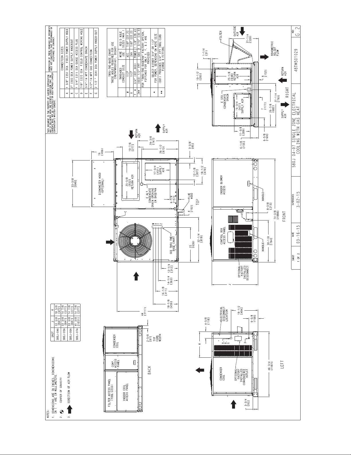
Fig. 2 — Unit Dimensional Drawing
4
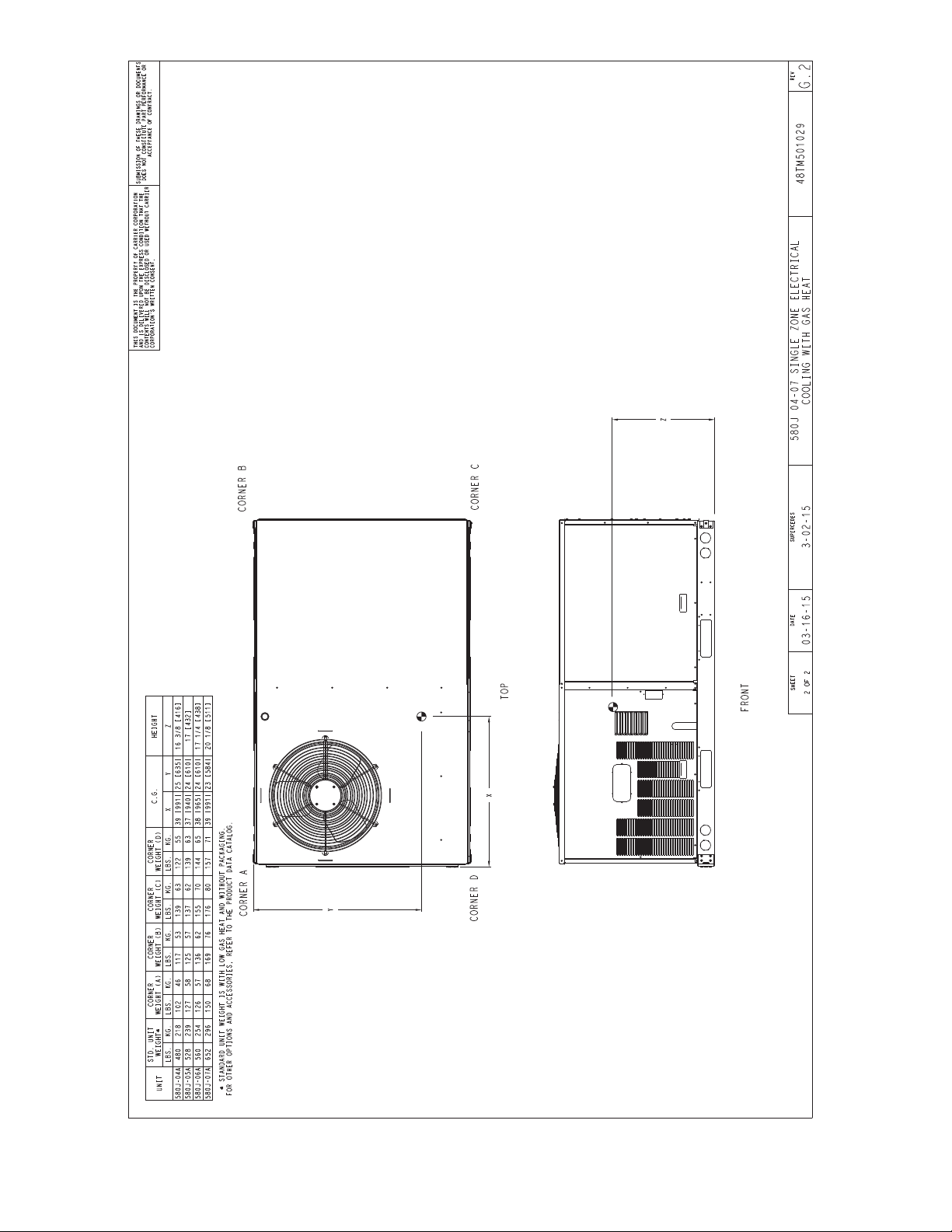
Fig. 2 — Unit Dimensional Drawing (cont)
5
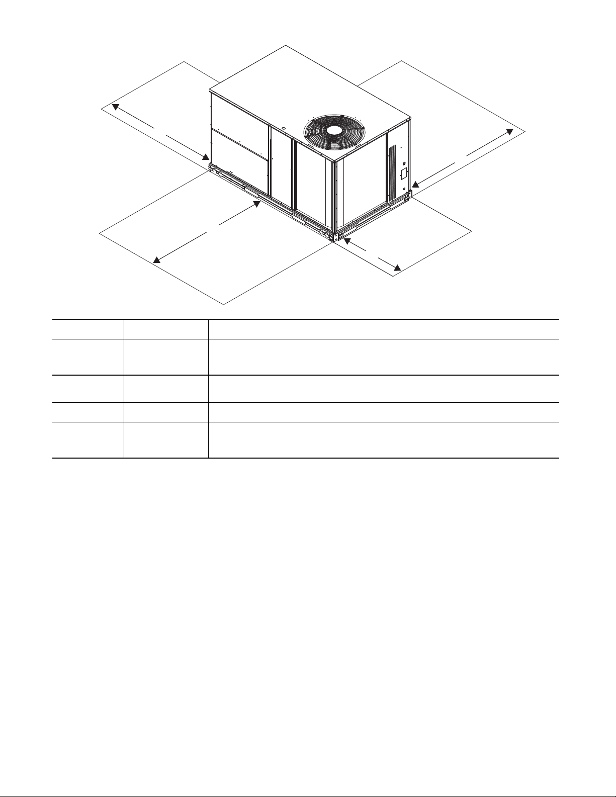
C
LOCATION
DIMENSION
in. (mm)
CONDITION
A
48 (1219)
18 (457)
18 (457)
12 (305)
Unit disconnect is mounted on panel.
No disconnect, convenience outlet option.
Recommended service clearance.
Minimum clearance.
B
42 (1067)
36 (914)
Special
Surface behind servicer is grounded (e.g., metal, masonry wall).
Surface behind servicer is electrically non-conductive (e.g., wood, fiberglass).
Check for sources of flue products within 10-ft of unit fresh air intake hood.
C
36 (914)
18 (457)
Side condensate drain is used.
Minimum clearance.
D
48 (1219)
42 (1067)
36 (914)
Special
No flue discharge accessory installed, surface is combustible material.
Surface behind servicer is grounded (e.g., metal, masonry wall, another unit).
Surface behind servicer is electrically non-conductive (e.g., wood, fiberglass).
Check for adjacent units or building fresh air intakes within 10-ft (3 m) of this unit’s flue outlet.
D
B
A
Fig. 3 — Service Clearances — 580J**04-07 Units
NOTE: Unit is not designed to have overhead obstruction.
Contact Application Engineering for guidance on any application planning overhead obstruction or for vertical clearances.
INSTALLATION
Job-Site Survey —
installation.
1. Consult local building codes and the NEC (National
Electrical Code) ANSI/NFPA 70 for special installation requirements.
2. Determine unit location (from project plans) or select unit
location.
3. Check for possible overhead obstructions which may interfere with unit lifting or rigging.
Step 1 — Plan for Unit Location — Select a location
for the unit and its support system (curb or other) that provides
for the minimum clearances required for safety. This includes
the clearance to combustible surfaces, unit performance and
service access below, around and above unit as specified in unit
drawings. See Fig. 2.
NOTE: Consider also the effect of adjacent units. Be sure
that unit is installed such that snow will not block the combustion intake or flue outlet.
Complete the following checks before
Unit may be installed directly on wood flooring or on Class
A, B, or C roof-covering material when roof curb is used.
Do not install unit in an indoor location. Do not locate air inlets near exhaust vents or other sources of contaminated air. For
proper unit operation, adequate combustion and ventilation air
must be provided in accordance with Section 5.3 (Air for Combustion and Ventilation) of the National Fuel Gas Code, ANSI
Z223.1 (American National Standards Institute) and NFPA
(National Fire Protection Association) 54 TIA-54-84-1. In
Canada, installation must be in accordance with the CAN1B149 installation codes for gas burning appliances.
Although unit is weatherproof, avoid locations that permit
water from higher level runoff and overhangs to fall onto the
unit.
Locate mechanical draft system flue assembly at least 4 ft
(1.2 m) from any opening through which combustion products
could enter the building, and at least 4 ft (1.2 m) from any adjacent building (or per local code). Locate the flue assembly at
least 10 ft (3.05 m) from an adjacent unit’s fresh air intake hood
if within 3 ft (0.91 m) of same elevation (or per local code).
When unit is located adjacent to public walkways, flue assembly must be at least 7 ft (2.1 m) above grade.
Select a unit mounting system that provides adequate height
to allow installation of condensate trap per requirements. Refer
to Step 11 — Install External Condensate Trap and Line – for
required trap dimensions.
6
ROOF MOUNT — Check building codes for weight dis-
A
B
C
A TO B
in. (mm)
B TO C
in. (mm)
A TO C
in. (mm)
0.5 (13) 1.0 (25) 1.0 (25)
tribution requirements. Unit operating weight is shown in
Table 2.
Step 2 — Plan for Sequence of Unit Installation —
The support method used for this unit will dictate different
sequences for the steps of unit installation. For example, on
curb-mounted units, some accessories must be installed on the
unit before the unit is placed on the curb. Review the following
for recommended sequences for installation steps.
CURB-MOUNTED INSTALLATION
1. Install curb
2. Install field-fabricated ductwork inside curb
3. Install accessory thru-base service connection package
(affects curb and unit) (refer to accessory installation instructions for details)
4. Prepare bottom condensate drain connection to suit
planned condensate line routing (refer to Step 11 for details)
5. Rig and place unit
6. Install outdoor air hood
7. Install flue hood
8. Install gas piping
9. Install condensate line trap and piping
10. Make electrical connections
11. Install other accessories
PAD-MOUNTED INSTALLATION
1. Prepare pad and unit supports
2. Check and tighten the bottom condensate drain connection plug
3. Rig and place unit
4. Convert unit to side duct connection arrangement
5. Install field-fabricated ductwork at unit duct openings
6. Install outdoor air hood
7. Install flue hood
8. Install gas piping
9. Install condensate line trap and piping
10. Make electrical connections
11. Install other accessories
FRAME-MOUNTED INSTALLATION — Framemounted applications generally follow the sequence for a curb
installation. Adapt as required to suit specific installation plan.
Step 3 — Inspect Unit — Inspect unit for transportation
damage. File any claim with transportation agency. Confirm
before installation of unit that voltage, amperage and circuit
protection requirements listed on unit data plate agree with
power supply provided.
Step 4 — Provide Unit Support
ROOF CURB MOUNT — Curb should be level. This is
necessary for unit drain to function properly. Unit leveling tolerances are show in Fig. 4. Refer to Accessory Roof Curb Installation Instructions for additional information as required.
Fig. 4 — Unit Leveling Tolerances
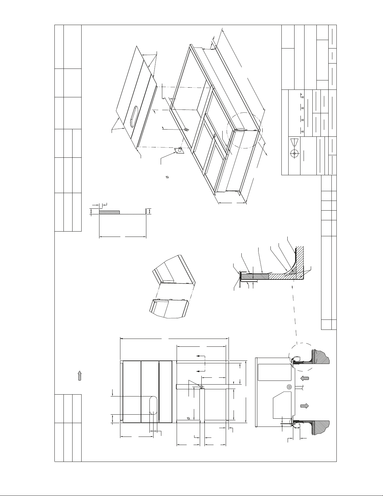
Accessory roof curb details and dimensions are shown in
Fig. 5. Assemble and install accessory roof curb in accordance
with instructions shipped with the curb.
NOTE: The gasketing of the unit to the roof curb is critical
for a watertight seal. Install gasket supplied with the roof
curb as shown in Fig. 5. Improperly applied gasket can also
result in air leaks and poor unit performance.
Install insulation, cant strips, roofing felt, and counter flashing as shown. Ductwork must be attached to curb and not to the
unit. The accessory thru-the-base power and gas connection
package must be installed before the unit is set on the roof curb.
If field-installed thru-the-roof curb gas connections are desired,
use factory-supplied
bly to mount the thru-the-roof curb connection to the roof curb.
Gas connections and power connections to the unit must be
field installed after the unit is installed on the roof curb.
If electric and control wiring is to be routed through the
basepan, attach the accessory thru-the-base service connections
to the basepan in accordance with the accessory installation
instructions.
SLAB MOUNT (HORIZONTAL UNITS ONLY) —
Provide a level concrete slab that extends a minimum of 6 in.
(150 mm) beyond unit cabinet. Install a gravel apron in front of
condenser coil air inlet to prevent grass and foliage from obstructing airflow.
NOTE: Horizontal units may be installed on a roof curb if
required.
ALTERNATE UNIT SUPPORT (IN LIEU OF CURB
OR SLAB MOUNT) — A non-combustible sleeper rail can
be used in the unit curb support area. If sleeper rails cannot be
used, support the long sides of the unit with a minimum of
three equally spaced 4-in. x 4-in. (102 mm x 102 mm) pads on
each side.
1
/2-in. pipe coupling and gas plate assem-
Table 2 — Operating Weights
580J
Base Unit 438 (199) 494 (224) 524 (238) 607 (275)
Economizer 35 (16) 35 (16) 35 (16) 35 (16)
Perfect Humidity™ System 15 (7) 15 (7) 15 (7) 24 (7)
Cu Fins 25 (11) 43 (20) 56 (25) 73 (33)
Powered Outlet 32 (15) 32 (15) 32 (15) 32 (15)
Curb
14-in. (356 mm) 110 (50) 110 (50) 110 (50) 110 (50)
16-in. (610 mm) 145 (66) 145 (66) 145 (66) 145 (66)
04 05 06 07
UNITS — lb (kg)
7
E
E
7/16"
[11]
4 9/16"
[115.5]
1/4"
[7.0]
5' 7-3/8"
[1711.3]
1' 4-13/16"
[427] INSIDE
1-3/4"
[44.4]
2-3/8"
[61]
1-3/4"
[44.5]
1.00"
[25.4]
"A"
1-3/4"
[44.4]
21.74"
[552.2]
5.42"
[137.7]
11.96"
[303.8]
4.96"
[126.0]
70.87"
[1800.2]
40.69"
[1033.5]
21.84"
[554.7]
16.03"
[407.2]
1.75"
[44.5]
20.41"
[518.3]
3.00"
[76.2]
13.78"
[350.0]
14.00"
[355.6]
3.00"
[76.2]
15.19"
[385.8]
32.19"
[817.6]
3'-1 3/16"
[944.6]
"A"
1-3/4"
[44.5]
CRBTMPWR001A01 3/4" [19] NPT
3/4" [19] NPT
1/2" [12.7] NPTCRRFCURB002A01
CONNECTOR PKG. ACC.
GAS CONNECTION TYPE
GAS FITTING
POWER WIRING
FITTING
CONTROL WIRING
FITTING
ACCESSORY CONVENIENCE
OUTLET WIRING CONNECTOR
THRU THE CURB
1/2" [12.7] NPT 1/2" [12.7] NPT
CRBTMPWR003A01
THRU THE BOTTOM
ROOF CURB
ACCESSORY #
A
CRRFCURB001A01
14"
[356]
24"
[610]
ECN NO.APP'DCHK'DBYDATEREVISION RECORDREV
1067898CMM--04/22/13
OVERALL DIM. 5'-7 3/8" WAS 5'-7 7/8; 18GA
MATERIAL WA 16 GA.; NAIL FIELD SUPPLIED WAS
WITH CURB
A
DRAWING RELEASE LEVEL:
PRODUCTION
THIRD ANGLE
PROJECTION
UNLESS OTHERWISE SPECIFIED
DIMENSIONS ARE IN INCHES
TOLERANCES ON:
THIS DOCUMENT AND THE INFORMATION CONTAINED THEREIN
IS PROPRIETARY TO CARRIER CORPORATION AND SHALL NOT
BE USED OR DISCLOSED TO OTHERS, IN WHOLE OR IN PART,
WITHOUT THE WRITTEN AUTHORIZATION OF CARRIER CORPORATION.
1 DEC 2 DEC 3 DEC ANG
MATERIAL
----
---
AUTHORIZATION NUMBER TITLE
1041738
CURB ASY, ROOF
ENGINEERING
(004-007)
ENGINEERING REQUIREMENTS
-
-
-
-
SIZE DRAWING NUMBER REV
T-005, Y-002
DRAFTER CHECKER
D
48TC400427
B
WEIGHT:
-
MMC 06/17/11 - -
SHEET 5 OF 5
SURFACE FINISH MFG/PURCH MODEL (INTERNAL USE ONLY) NEXT DRAWING SCALE DISTRIBUTION
-PURCH - N/A MMC
NOTES:
1. ROOFCURB ACCESSORY IS SHIPPED DISASSEMBLED.
2. INSULATED PANELS: 25.4 [1"] THK. POLYURETHANE FOAM, 44.5 [1-3/4] # DENSITY.
3. DIMENSIONS IN [ ] ARE IN MILLIMETERS.
4. ROOFCURB: 18 GAGE STEEL.
5. ATTACH DUCTWORK TO CURB. (FLANGES OF DUCT REST ON CURB).
6. SERVICE CLEARANCE 4 FEET ON EACH SIDE.
7. DIRECTION OF AIR FLOW.
8. CONNECTOR PACKAGE CRBTMPWR001A01 IS FOR THRU-THE-CURB GAS TYPE
PACKAGE CRBTMPWR003A01 IS FOR THRU-THE-BOTTOM TYPE GAS CONNECTIONS.
TYPICAL (4) SIDES
SUPPLY AIR RETURN AIR
ROOFING MATERIAL
(FIELD SUPPLIED)
CANT STRIP
(FIELD SUPPLIED)
ROOFING FELT
(FIELD SUPPLIED)
COUNTER FLASHING
(FIELD SUPPLIED)
UNIT
GASKET
(SUPPLIED WITH CURB)
RIGID INSULATION
(FIELD SUPPLIED)
DUCT
(FIELD SUPPLIED)
NAIL (FIELD SUPPLIED)
CERTIFIED DRAWING
VIEW "B"
CORNER DETAIL
SEE VIEW "B"
RETURN AIR
SUPPLY AIR
SUPPLY AIR
OPENING
RETURN AIR
OPENING
GAS SERVICE PLATE
THRU THE CURB
DRILL HOLE
2" [50.8] @
ASSEMBLY (IF
REQUIRED)
(SEE NOTE #8)
SEE NOTE #2
11 3/4"[298.5] WIDE
INSULATED DECK PANELS
8 9/16"[217.5] WIDE
INSULATED DECK PANEL
1/3/4"[44.5]
SCALE 0.250
E-E
SECTION
8
Fig. 5 — Roof Curb Details
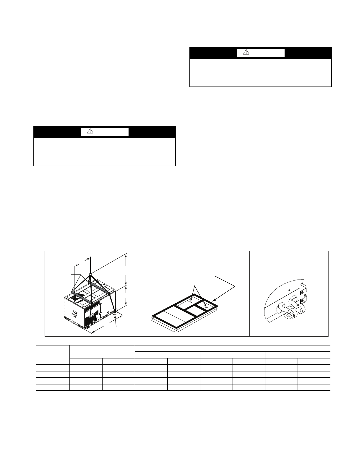
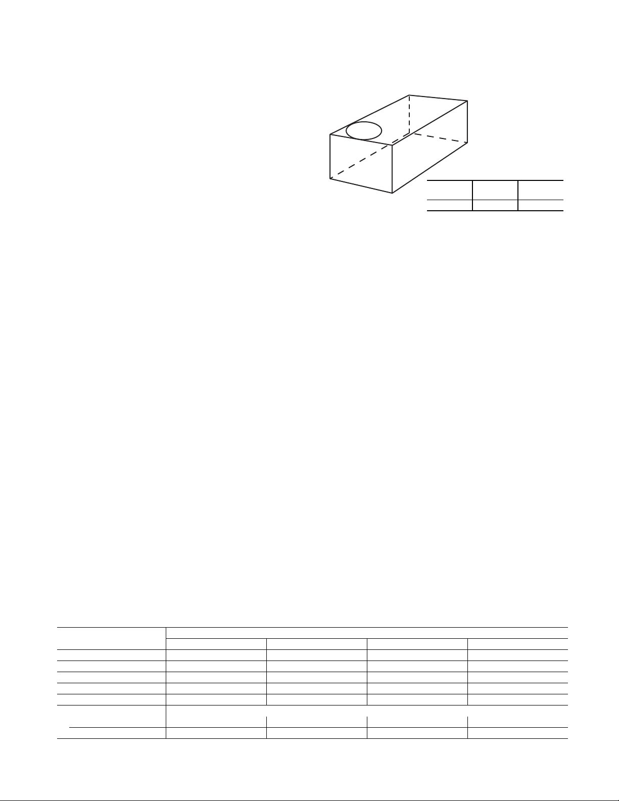
Step 5 — Field Fabricate Ductwork — Cabinet
DETAIL "A"
PLACE ALL SEAL STRIP IN PLACE
BEFORE PLACING UNIT ON ROOF CURB.
DUCT END
SEE DETAIL "A"
"A"
(914-1371)
36"- 54"
"C"
"B"
SPREADER
BARS
REQUIRED
NOTES:
1. SPREADER BARS REQUIRED — Top damage will occur if spreader bars are not used.
2. Dimensions in () are in millimeters.
3. Hook rigging shackles through holes in base rail, as shown in detail “A.” Holes in base rails are centered around the unit center of gravity. Use wooden top to prevent
rigging straps from damaging unit.
4. Max weight includes the base unit plus shipping pallet plus all available FIOPs which could be on that size unit.
UNIT
MAX WEIGHT
DIMENSIONS
A B C
LB KG LB KG LB KG LB KG
580J-04A 772 350 74.5 1890 39.0 990 33.5 850
580J-05A 826 375 74.5 1890 39.0 990 33.5 850
580J-06A 896 406 74.5 1890 39.0 990 33.5 850
580J-07A 1075 489 74.5 1890 39.0 990 41.5 1055
return-air static pressure (a negative condition) shall not
exceed 0.35 in. wg (87 Pa) with economizer or 0.45 in. wg
(112 Pa) without economizer. For vertical ducted applications, secure all ducts to roof curb and building structure.
Do not connect ductwork to unit. Fabricate supply
ductwork so that the cross sectional dimensions are equal
to or greater than the unit supply duct opening dimensions
for the first 18 in. (458 mm) of duct length from the unit
basepan. Insulate and weatherproof all external ductwork,
joints, and roof openings with counter flashing and mastic
in accordance with applicable codes.
Ducts passing through unconditioned spaces must be insulated and covered with a vapor barrier. If a plenum return is
used on a vertical unit, the return should be ducted through the
roof deck to comply with applicable fire codes.
A minimum clearance is not required around ductwork.
CAUTION
Failure to follow this caution may result in damage to roofing materials.
Membrane roofs can be cut by sharp sheet metal edges. Be
careful when placing any sheet metal parts on such roof.
Step 6 — Rig and Place Unit — Keep unit upright and
do not drop. Spreader bars are required. Rollers may be used to
move unit across a roof. Level by using unit frame as a reference. See Table 1 and Fig. 6 for additional information.
Lifting holes are provided in base rails as shown in Fig. 6.
Refer to rigging instructions on unit.
Rigging materials under unit (cardboard or wood to prevent
base pan damage) must be removed PRIOR to placing the unit
on the roof curb. When using the standard side drain connection, ensure the red plug in the alternate bottom connection is
tight. Do this before setting the unit in place. The red drain pan
can be tightened with a
1
/2-in. square socket drive extension.
For further details see Step 11 — Install External Condensate
Trap and Line on page 14.
Before setting the unit onto the curb, recheck gasketing on
curb.
CAUTION
Failure to follow this caution may result in equipment
damage.
All panels must be in place when rigging. Unit is not
designed for handling by fork truck.
POSITIONING ON CURB — Position unit on roof curb so
that the following clearances are maintained:
clearance between the roof curb and the base rail inside the
front and back, 0.0 in. clearance between the roof curb and the
base rail inside on the duct end of the unit. This will result in
the distance between the roof curb and the base rail inside on
the condenser end of the unit being approximately
(6.4 mm).
Although unit is weatherproof, guard against water from
higher level runoff and overhangs.
Flue vent discharge must have a minimum horizontal clearance of 4 ft (1220 mm) from electric and gas meters, gas regulators, and gas relief equipment. Minimum distance between
unit and other electrically live parts is 48 inches (1220 mm).
Flue gas can deteriorate building materials. Orient unit such
that flue gas will not affect building materials. Locate mechanical draft system flue assembly at least 48 in. (1220 mm) from
an adjacent building or combustible material.
NOTE: Installation of accessory flue discharge deflector kit
will reduce the minimum clearance to combustible material
to 18 in. (460 mm).
After unit is in position, remove rigging skids and shipping
materials.
1
/4 in. (6.4 mm)
1
/4 in.
Fig. 6 — Rigging Details
9
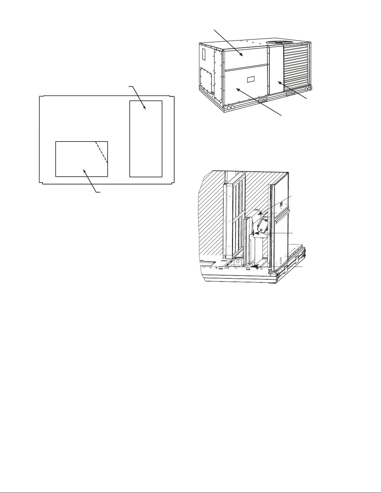
Step 7 — Convert to Horizontal and Connect
REMOVABLE HORIZONTAL
RETURN DUCT OPENING COVER
REMOVABLE HORIZONTAL
SUPPLY DUCT OPENING COVER
COMPRESSOR
ACCESS PANEL
OUTDOOR-AIR OPENING AND
INDOOR COIL ACCESS PANEL
FILTER ACCESS PANEL
Hood Parts
Plastic Tie Wrap
Qty (2)
Screws for Metal Tray
Qty (2)
Ductwork (when required) —
tical duct configuration. Unit without factory-installed economizer or return air smoke detector option may be field-converted to horizontal ducted configuration. To convert to horizontal
configuration, remove screws from side duct opening covers
and remove covers. Using the same screws, install covers on
vertical duct openings with the insulation-side down. Seals
around duct openings must be tight. See Fig. 7.
Unit is shipped in the ver-
Fig. 8 — Typical Access Panel Locations
3. Locate the (2) screws holding the metal tray to the base-
pan and remove. Locate and cut the (2) plastic tie-wraps
securing the assembly to the damper. (See Fig. 9.) Be
careful to not damage any wiring or cut tie-wraps securing any wiring.
Fig. 7 — Horizontal Conversion Panels
Field-supplied flanges should be attached to horizontal duct
openings and all ductwork should be secured to the flanges. Insulate and weatherproof all external ductwork, joints, and roof
or building openings with counter flashing and mastic in accordance with applicable codes.
Do not cover or obscure visibility to the unit’s informative
data plate when insulating horizontal ductwork.
Step 8 — Install Outside Air Hood
ECONOMIZER AND TWO POSITION DAMPER HOOD PACKAGE REMOVAL AND SETUP — FACTORY OPTION
NOTE: Economizer and two position damper are not available as factory installed options for single phase (-J voltage
code) models.
1. The hood is shipped in knock-down form and must be
field assembled. The indoor coil access panel is used
as the hood top while the hood sides, divider and filter
are packaged together, attached to a metal support tray
using plastic stretch wrap, and shipped in the return air
compartment behind the indoor coil access panel. The
hood assembly’s metal tray is attached to the basepan
and also attached to the damper using two plastic tiewraps.
2. To gain access to the hood, remove the filter access panel.
See Fig. 8.
Fig. 9 — Economizer and Two-Position Damper Hood
Parts Location
4. Carefully lift the hood assembly (with metal tray) through
the filter access opening and assemble per the steps outlined in Economizer Hood and Two–Position Hood, below.
ECONOMIZER HOOD AND TWO-POSITION HOOD
NOTE: If the power exhaust accessory is to be installed on
the unit, the hood shipped with the unit will not be used and
must be discarded. Save the aluminum filter for use in the
power exhaust hood assembly.
10
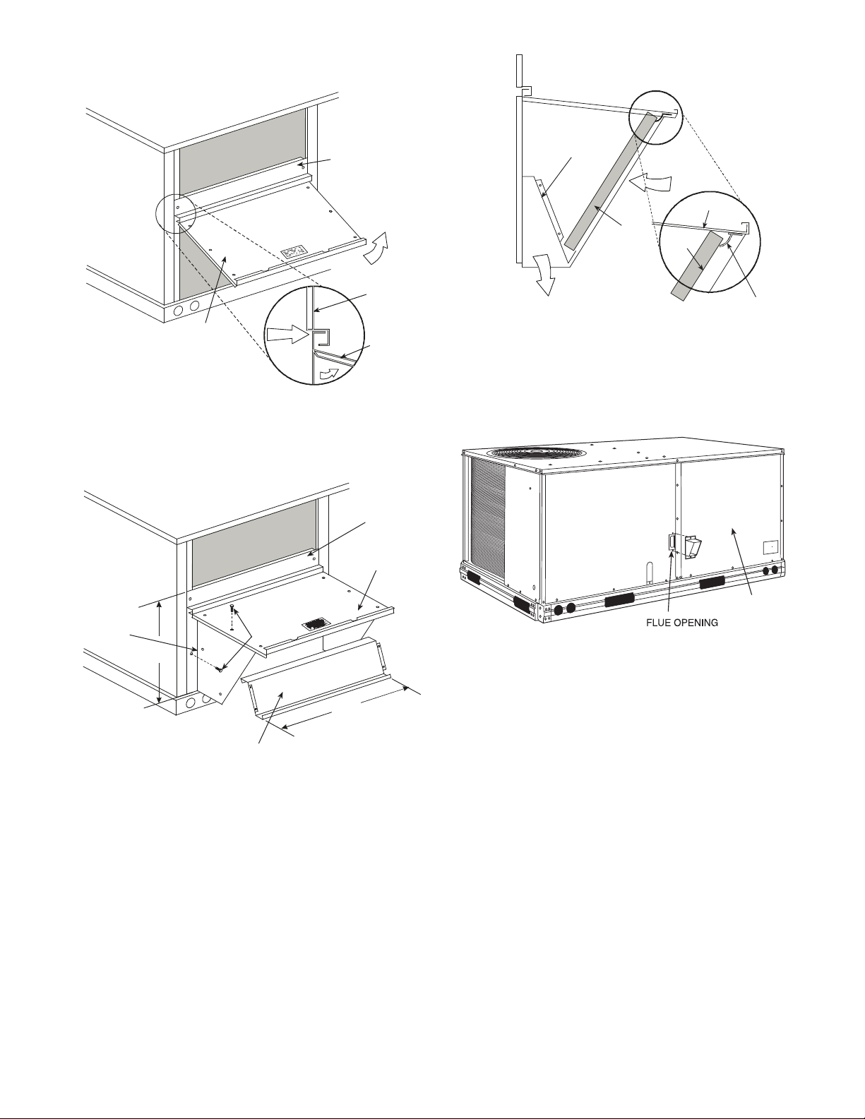
1. The indoor coil access panel will be used as the top of
B
TOP
PANEL
INDOOR COIL
ACCESS PANEL
19 1/16”
SCREW
HOOD DIVIDER
LEFT
HOOD
SIDE
33 3/8”
(848mm)
(483mm)
DIVIDER
BAROMETRIC
RELIEF
CLEANABLE
ALUMINUM
FILTER
FILTER
HOOD
FILTER
CLIP
OUTSIDE
AIR
BLOWER
ACCESS
PANEL
the hood. Remove the screws along the sides and bottom of the indoor coil access panel. See Fig. 10.
TOP
PANEL
TOP
PANEL
INDOOR
COIL
ACCESS
PANEL
INDOOR
COIL
ACCESS
PANEL
CAULK
HERE
Fig. 10 — Indoor Coil Access Panel Relocation
2. Swing out indoor coil access panel and insert the hood
sides under the panel (hood top). Use the screws provided
to attach the hood sides to the hood top. Use screws provided to attach the hood sides to the unit. See Fig. 11.
Fig. 12 — Economizer Filter Installation
Step 9 — Install Flue Hood
Flue hood is shipped screwed to the basepan beside the
burner compartment access panel. Remove from shipping location and using screws provided, install flue hood and screen in
location shown in Fig. 13.
Fig. 11 — Economizer Hood Construction
3. Remove the shipping tape holding the economizer barometric relief damper in place (economizer only).
4. Insert the hood divider between the hood sides. See
Fig. 11 and 12. Secure hood divider with 2 screws on
each hood side. The hood divider is also used as the bottom filter rack for the aluminum filter.
5. Open the filter clips which are located underneath the
hood top. Insert the aluminum filter into the bottom filter
rack (hood divider). Push the filter into position past the
open filter clips. Close the filter clips to lock the filter into
place. See Fig. 12.
6. Caulk the ends of the joint between the unit top panel and
the hood top.
7. Replace the filter access panel.
Fig. 13 — Flue Hood Details
Step 10 — Install Gas Piping
Installation of the gas piping must be accordance with local
building codes and with applicable national codes. In U.S.A.,
refer to NFPA 54/ANSI Z223.1 National Fuel Gas Code (NFGC). In Canada, installation must be accordance with the
CAN/CSA B149.1 and CAN/CSA B149.2 installation codes
for gas burning appliances. This unit is factory equipped for
use with Natural Gas fuel at elevations up to 2000 ft (610 m)
above sea level. Unit may be field converted for operation at elevations above 2000 ft (610 m) and/or for use with liquefied
petroleum fuel. See accessory kit installation instructions regarding these accessories.
NOTE: Furnace gas input rate on rating plate is for installation up to 2000 ft (610 m) above sea level. In U.S.A. the
input rating for altitudes above 2000 ft (610 m) must be derated by 4% for each 1000 ft (305 m) above sea level. In
Canada the input rating must be derated by 10% for altitudes of 2000 ft (610 m) to 4500 ft (1372 m) above sea
level.
For natural gas applications, gas pressure at unit gas connection must not be less than 4 in. wg (996 Pa) or greater than
13 in. wg (3240 Pa) while the unit is operating, see Table 3. For
liquefied petroleum applications, the gas pressure must not be
less than 11 in. wg (2740 Pa) or greater than 13.0 in. wg
(3240 Pa) at the unit connection, see Table 4.
11
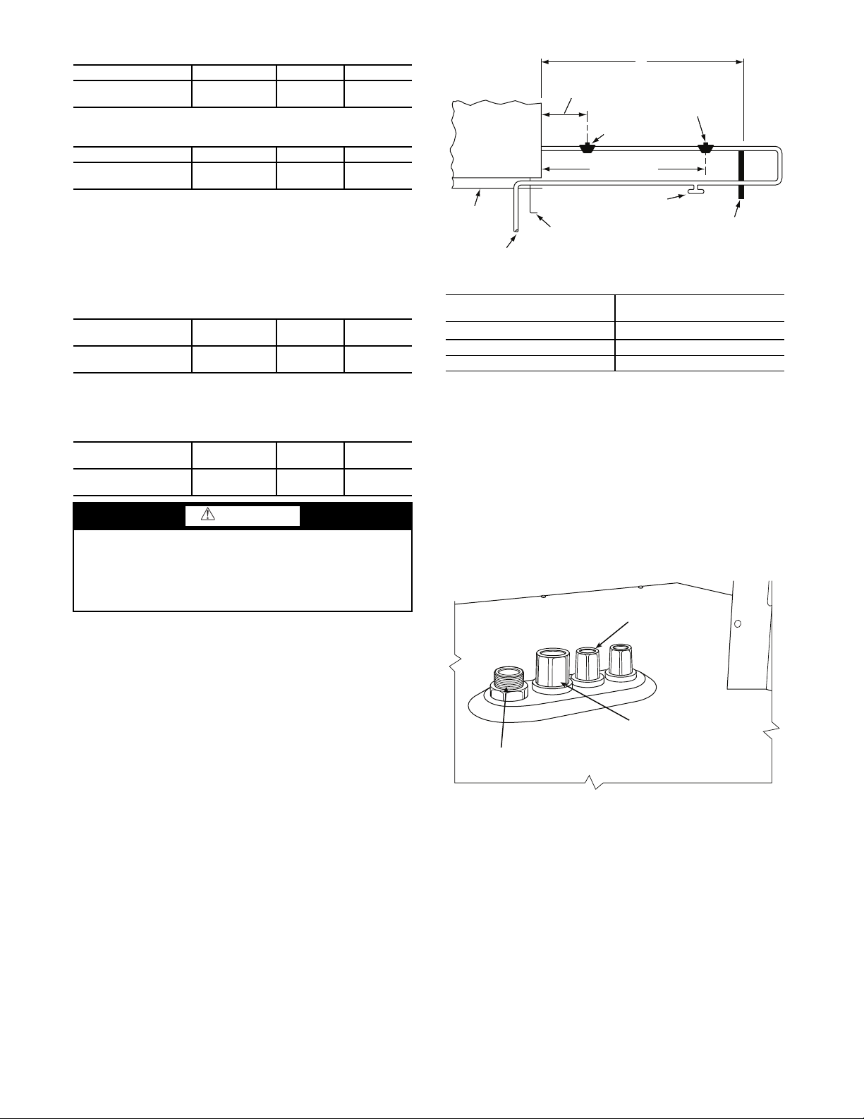
Table 3 — Natural Gas Supply Line Pressure Ranges
LEGEND
* Field-Supplied.
STEEL PIPE NOMINAL
DIAMETER (in.)
SPACING OF SUPPORTS X
DIMENSIONS (FT)
1
/
2
6
3
/
4
or 1 8
1
1
/
4
or larger 10
NFGC — National Fuel Gas Code
LOW VOLTAGE
CONDUIT
CONNECTOR
HIGH VOLTAGE
CONDUIT
CONNECTOR
BRASS FITTING FOR 3 TO 6 TON UNITS.
UNIT MODEL UNIT SIZE MIN. MAX.
580J* 04, 05, 06, 07
4.0 in. wg
(996 Pa)
13.0 in. wg
(3240 Pa)
Table 4 — Liquid Propane Supply Line Pressure
Ranges
UNIT MODEL UNIT SIZE MIN. MAX.
580J* 04, 05, 06, 07
11.0 in. wg
(2740 Pa)
13.0 in. wg
(3240 Pa)
The gas supply pipe enters the unit at the burner access panel on the front side of the unit, through the long slot at the bottom of the access panel. The gas connection to the unit is made
1
/2-in. FPT gas inlet port on the unit gas valve.
to the
Manifold pressure is factory-adjusted for NG fuel use. Adjust as required to obtain best flame characteristics. See Table 5
for ranges.
Table 5 — Natural Gas Manifold Pressure Ranges
UNIT MODEL UNIT SIZE
580J* 04, 05, 06, 07
HIGH
FIRE.
3.5 in. wg
(872 Pa)
LOW FIRE
1.7 in. wg
(423 Pa)
Manifold pressure for LP fuel use must be adjusted to specified range, see Table 6. Follow instructions in the accessory kit
to make initial readjustment.
Table 6 — Liquid Propane Manifold Pressure Ranges
UNIT MODEL UNIT SIZE
580J* 04, 05, 06, 07
HIGH
FIRE.
10.0 in. wg
(2490 Pa)
LOW FIRE
5.0 in. wg
(1245 Pa)
CAUTION
Failure to follow this caution may result in damage to
equipment.
When connecting the gas line to the unit gas valve, the
installer MUST use a backup wrench to prevent damage to
the valve.
X
9” MINIMUM CLEARANCE
BASE UNIT
BASE RAIL
FROM
GAS
METER
FOR PANEL REMOVAL
MANUAL GAS
SHUTOFF VALVE
48” MINIMUM
ROOF
CURB
DRIP LEG
PER NFGC
GAS
REGULATOR
*
*
FIELD-FABRICATED
SUPPORT
*
*
Fig. 14 — Gas Piping Guide (with Accessory Thru-the-
Curb Service Connections)
FACTORY-OPTION THRU-BASE CONNECTIONS
(GAS CONNECTIONS) — This service connection kit
consists of a
electrical bulkhead connector and a
1
/2-in. NPT gas adapter fitting (brass), a 1/2-in.
3
/4-in. electrical bulkhead
connector, all factory-installed in the embossed (raised) section
of the unit basepan in the condenser section. See Fig. 15.
Install a gas supply line that runs to the unit heating section.
Refer to the NFPA 54/NFGC or equivalent code for gas pipe
sizing data. Do not use a pipe size smaller than
gas supply line to allow for a maximum pressure drop of 0.5in.wg (124 Pa) between gas regulator source and unit gas valve
connection when unit is operating at high-fire flow rate.
The gas supply line can approach the unit in three ways:
horizontally from outside the unit (across the roof), thru-curb/
under unit basepan (accessory kit required) or through unit
basepan (factory-option or accessory kit required). Consult accessory kit installation instructions for details on these installation methods. Observe clearance to gas line components per
Fig. 14.
1
/2-in. Size the
Fig. 15 — Thru-Base Connection Fittings
The thru-base gas connector has male and female threads.
The male threads protrude above the basepan of the unit; the
female threads protrude below the basepan.
Check tightness of connector lock nuts before connecting
gas piping.
Install a
Attach a
1
/2-in. NPT street elbow on the thru-base gas fitting.
1
/2-in. pipe nipple with minimum length of 16-in.
(406 mm) (field-supplied) to the street elbow and extend it
through the access panel at the gas support bracket. See Fig. 16.
12
EMBOSSMENT
9” (229mm) min
Union
Shut Off
Valve
Drip
Leg
Thru-Curb Adapter
Unit Base Rail
Drip
Leg
Shut Off
Valve
Union
Thru-Curb Adapter
Burner
Access
Panel
9” (229mm) min
Unit Base Rail
BRASS FITTING
FOR 3-6 TON UNITS
SUPPORT
BRACKET
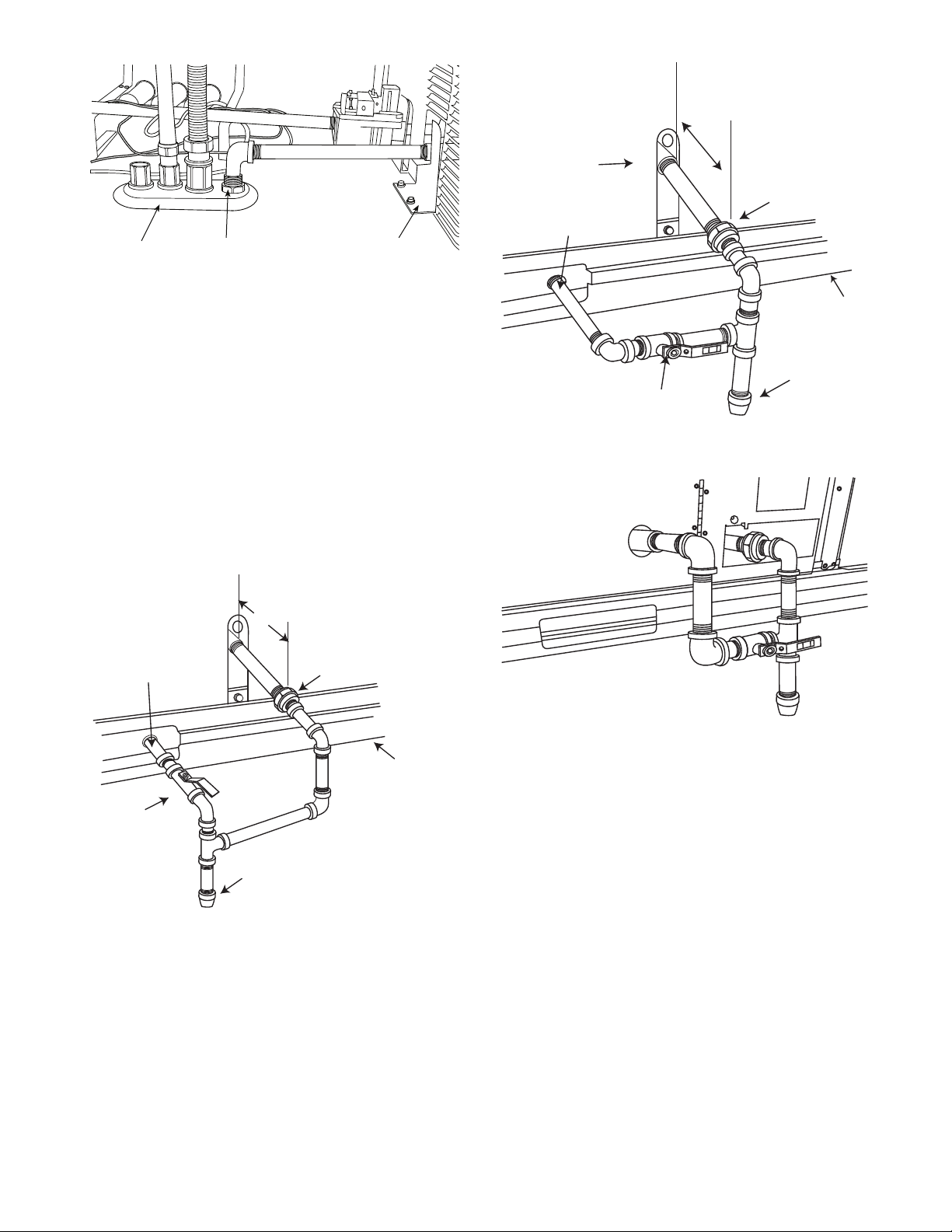
Fig. 16 — Gas Line Piping (3 to 6 Ton Units Only)
Other hardware required to complete the installation of the
gas supply line will include a manual shutoff valve, a sediment
trap (drip leg) and a ground-joint union. A pressure regulator
valve may also be required (to convert gas pressure from
pounds to inches of pressure). The manual shutoff valve must
be located within 6-ft (1.83 m) of the unit. The union, located
in the final leg entering the unit, must be located at least 9-in.
(230 mm) away from the access panel to permit the panel to be
removed for service. If a regulator valve is installed, it must be
located a minimum of 4-ft (1220 mm) away from the unit’s
flue outlet. Some municipal codes require that the manual shutoff valve be located upstream of the sediment trap. See Fig. 17
and 18 for typical piping arrangements for gas piping that has
been routed through the sidewall of the curb. See Fig. 19 for
typical piping arrangement when thru-base is used. Ensure that
all piping does not block access to the unit’s main control box
or limit the required working space in front of the control box.
Fig. 18 — Gas Piping with Thru-Curb Accessory
(Alternate Layout)
Fig. 17 — Gas Piping with Thru-Curb Accessory
Fig. 19 — Gas Piping Thru-Base Connections
When installing the gas supply line, observe local codes
pertaining to gas pipe installations. Refer to the NFPA 54/
ANSI Z223.1 NFGC latest edition (in Canada, CAN/CSA
B149.1). In the absence of local building codes, adhere to the
following pertinent recommendations:
1. Avoid low spots in long runs of pipe. Grade all pipe
1
/4-in. in every 15 ft (7 mm in every 5 m) to prevent
traps. Grade all horizontal runs downward to risers.
Use risers to connect to heating section and to meter.
2. Protect all segments of piping system against physical
and thermal damage. Support all piping with appropriate
straps, hangers, etc. Use a minimum of one hanger every
6 ft (1.8 m). For pipe sizes larger than
1
/2-in., follow rec-
ommendations of national codes.
3. Apply joint compound (pipe dope) sparingly and only to
male threads of joint when making pipe connections. Use
only pipe dope that is resistant to action of liquefied petroleum gases as specified by local and/or national codes.
If using PTFE (Teflon*) tape, ensure the material is Double Density type and is labeled for use on gas lines. Apply
tape per manufacturer’s instructions.
4. Pressure-test all gas piping in accordance with local and
national plumbing and gas codes before connecting piping to unit.
* Teflon is a registered trademark of DuPont.
13
NOTE: Pressure test the gas supply system after the gas
BURNER
ORIFICE
DRAIN
(FACTORY-INSTALLED)
PLUG
CONDENSATE PAN (SIDE VIEW)
STANDARD
SIDE DRAIN
ALTERNATE
BOTTOM DRAIN
MINIMUM PITCH
1” (25mm) PER
10’ (3m) OF LINE
BASE RAIL
OPEN
VENT
TO ROOF
DRAIN
DRAIN PLUG
ROOF
CURB
SEE NOTE
2 in.
(51) MIN
supply piping is connected to the gas valve. The supply piping must be disconnected from the gas valve during the testing of the piping systems when test pressure is in excess of
0.5 psig (3450 Pa). Pressure test the gas supply piping system at pressures equal to or less than 0.5 psig (3450 Pa).
The unit heating section must be isolated from the gas piping system by closing the external main manual shutoff
valve and slightly opening the ground-joint union.
Check for gas leaks at the field-installed and factory-installed gas lines after all piping connections have been completed. Use soap-and-water solution (or method specified by
local codes and/or regulations).
WARNING
Failure to follow this warning could result in personal
injury, death and/or property damage.
• Connect gas pipe to unit using a backup wrench to
avoid damaging gas controls.
• Never purge a gas line into a combustion chamber.
• Never test for gas leaks with an open flame. Use a
commercially available soap solution made specifically for the detection of leaks to check all connections.
• Use proper length of pipe to avoid stress on gas control manifold.
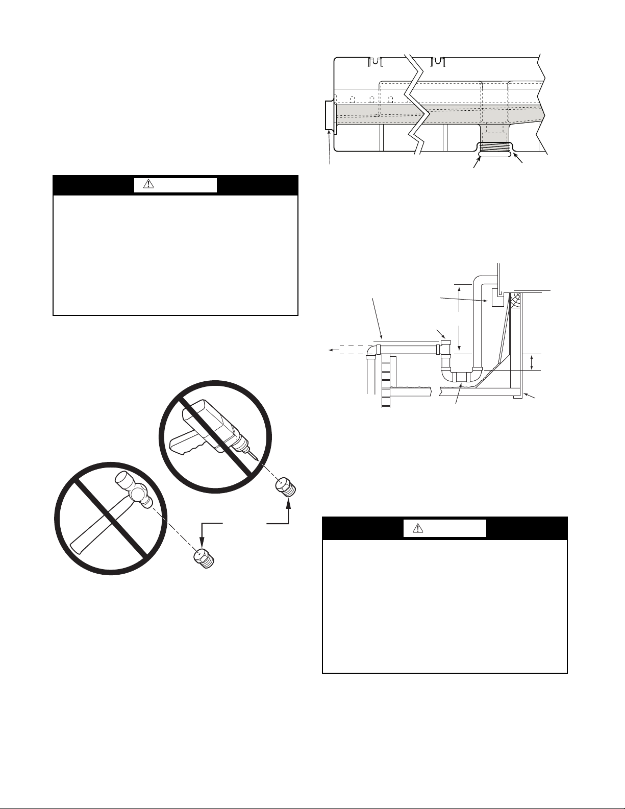
NOTE: If orifice hole appears damaged or it is suspected to
have been re-drilled, check orifice hole with a numbered
drill bit of correct size. Never re-drill an orifice. A burr-free
and squarely aligned orifice hole is essential for proper
flame characteristics. See Fig. 20.
Fig. 21 — Condensate Drain Pan (Side View)
The piping for the condensate drain and external trap can be
completed after the unit is in place. See Fig. 22.
NOTE: If the alternate bottom drain is not used check the
drain plug for tightness prior to setting the unit on the roof
curb.
Fig. 20 — Orifice Hole
Step 11 — Install External Condensate Trap and
Line —
on the end of the condensate pan and an alternate connection
on the bottom. See Fig. 21. Unit airflow configuration does not
determine which drain connection to use. Either drain connection can be used with vertical or horizontal applications.
red drain plug from the bottom connection (use a
square socket drive extension) and install it in the side drain
connection.
The unit has one 3/4-in. condensate drain connection
To use the alternate bottom drain connection, remove the
1
/2-in.
Fig. 22 — Condensate Drain Piping Details
All units must have an external trap for condensate drainage. Install a trap at least 4-in. (102 mm) deep and protect
against freeze-up. If drain line is installed downstream from the
external trap, pitch the line away from the unit at 1-in. per 10 ft
(25 mm in 3 m) of run. Do not use a pipe size smaller than the
unit connection (
3
/4-in.).
Step 12 — Make Electrical Connections
WARNING
Failure to follow this warning could result in personal
injury or death.
Do not use gas piping as an electrical ground. Unit cabinet
must have an uninterrupted, unbroken electrical ground to
minimize the possibility of personal injury if an electrical
fault should occur. This ground may consist of electrical
wire connected to unit ground lug in control compartment,
or conduit approved for electrical ground when installed in
accordance with NEC (National Electrical Code); ANSI/
NFPA 70, latest edition (in Canada, Canadian Electrical
Code CSA [Canadian Standards Association] C22.1), and
local electrical codes.
NOTE: Field-supplied wiring shall conform with the limitations of minimum 63°F (33°C) rise.
14
FIELD POWER SUPPLY — If equipped with optional
Disconnect
per
NEC
Disconnect
per
NEC
208/230-1-60
11
13
11
13 13
L1
L2 L3
TB
C
CIFC
or
(1-ph
IFM)
208/230-3-60
460-3-60
375-3-60
575-3-60
Units Without Disconnect Option
Units With Disconnect Option
2
4
6
1
3
5
L1
L2
L3
Optional
Disconnect
Switch
Disconnect factory test leads; discard.
Factory
Wiring
Powered Convenience Outlet: The power source leads to the
convenience outlet’s transformer primary are not factory connected. Installer must connect these leads according to required
operation of the convenience outlet. If an always-energized
convenience outlet operation is desired, connect the source
leads to the line side of the unit-mounted disconnect. (Check
with local codes to ensure this method is acceptable in your area.) If a de-energize via unit disconnect switch operation of the
convenience outlet is desired, connect the source leads to the
load side of the unit disconnect. On a unit without a unitmounted disconnect, connect the source leads to compressor
contactor C and indoor fan contactor IFC pressure lugs with
unit field power leads.
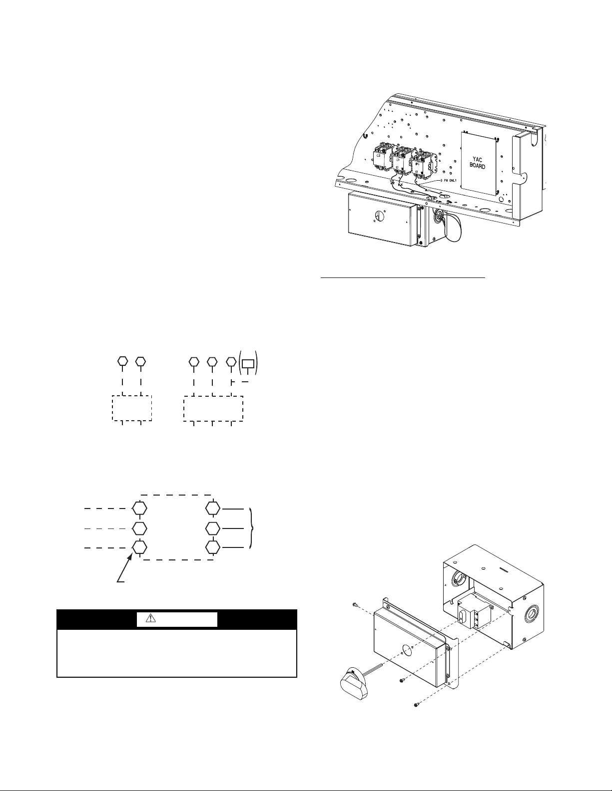
Refer to Fig. 23 for power transformer connections and the
discussion on connecting the convenience outlet on page 18.
Field power wires are connected to the unit at line-side pressure lugs on compressor contactor C and indoor fan contactor
IFC (see wiring diagram label for control box component arrangement) or at factory-installed option non-fused disconnect
switch. Max wire size is #2 AWG (copper only). (See Fig. 23.)
NOTE: TEST LEADS - Unit may be equipped with short
leads (pigtails) on the field line connection points on contactor
C or optional disconnect switch. These leads are for factory
run-test purposes only; remove and discard before connecting
field power wires to unit connection points. Make field power
connections directly to line connection pressure lugs only.
Assemble the shaft and handle to the switch at this point. Discard the factory test leads (see Fig. 24).
Connect field power supply conductors to LINE side terminals when the switch enclosure cover is removed to attach the
handle.
Fig. 24 — Location of Non-Fused Disconnect Enclosure
To field install the NFD shaft and handle
1. Remove the unit front pane (see Fig. 2).
2. Remove (3) hex screws on the NFD enclosure - (2) on the
face of the cover and (1) on the left side cover (see
Fig. 25).
3. Remove the front cover of the NFD enclosure.
4. Make sure the NFD shipped from the factory is at OFF
position (the arrow on the black handle knob is at OFF).
5. Insert the shaft with the cross pin on the top of the shaft in
the horizontal position.
6. Measure from the tip of the shaft to the top surface of the
black pointer; the measurement should be 3.75 to 3.88 in.
(95 to 99 mm).
7. Tighten the locking screw to secure the shaft to the NFD.
8. Turn the handle to the OFF position with red arrow pointing at OFF.
9. Install the handle on to the painted cover horizontally
with the red arrow pointing to the left.
10. Secure the handle to the painted cover with (2) screws
and lock washers supplied.
11. Engaging the shaft into the handle socket, re-install (3)
hex screws on the NFD enclosure.
12. Re-install the unit front panel.
Failure to follow this warning could result in intermittent
operation or performance satisfaction.
Do not connect aluminum wire between disconnect switch
Fig. 23 — Power Wiring Connections
WARNING
and 580J unit. Use only copper wire. (See Fig. 24)
UNITS WITH FACTORY-INSTALLED NON-FUSED
DISCONNECT — The factory-installed option non-fused
disconnect (NFD) switch is located in a weatherproof enclosure located under the main control box. The manual switch
handle and shaft are shipped in the disconnect enclosure.
Fig. 25 — Handle and Shaft Assembly for NFD
15
UNITS WITHOUT FACTORY-INSTALLED NON-
ABC
MOTOR
FUSED DISCONNECT — When installing units, provide a
disconnect switch per NEC (National Electrical Code) of adequate size. Disconnect sizing data is provided on the unit informative plate. Locate on unit cabinet or within sight of the unit
per national or local codes. Do not cover unit informative late if
mounting the disconnect on the unit cabinet.
All Units
— Field wiring must comply with NEC and all local
codes. Size wire based on MCA (Minimum Circuit Amps) on
the unit informative plate. See Fig. 23 and the unit label diagram for power wiring connections to the unit power terminal
blocks and equipment ground. Maximum wire size is #4 ga
AWG per pole.
Provide a ground-fault and short-circuit over-current protection device (fuse or breaker) per NEC Article 440 (or local
codes). Refer to unit informative data plate for MOCP (Maximum Over-current Protection) device size.
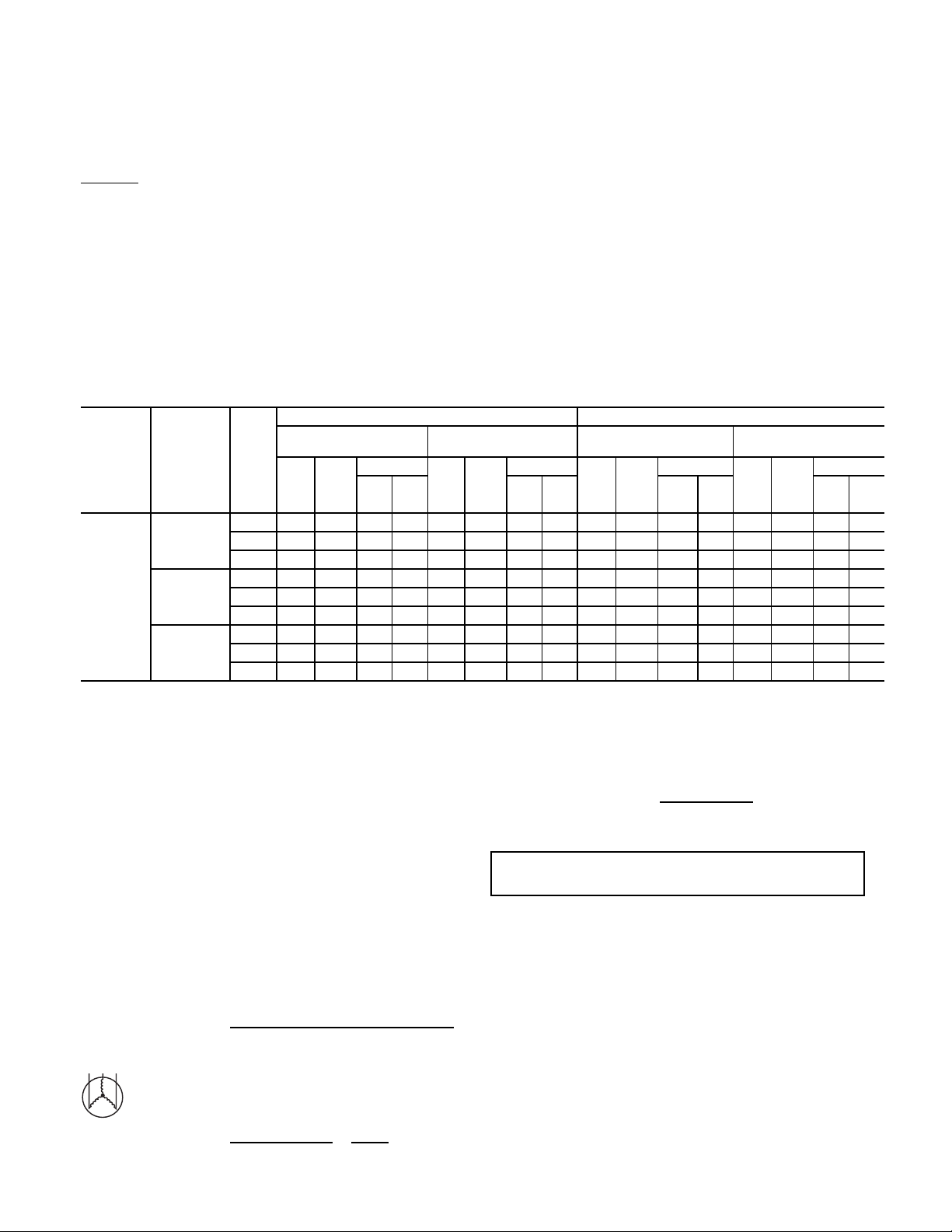
Table 7 — Unit Wire/Fuse or HACR Breaker Sizing Data — 2-Speed Indoor Fan Motor
NO C.O. OR UNPWR C.O. WITH PWRD C.O.
WITH P.E. (POWERED
MCA
UNIT
580J*A07
NOM. V-PH-HZIFM
208/230-3-60
460-3-60
575-3-60
TYPE
STD 34/33 50/50 32/32 167 35/35 50/50 35/34 169 38/38 50/50 38/38 172 40/40 50/50 40/40 174
MED 35/34 50/50 34/33 193 37/36 50/50 36/35 195 40/39 50/50 40/39 198 42/41 60/60 42/41 200
HIGH 37/36 50/50 37/36 217 39/38 50/50 39/38 219 42/41 60/60 42/41 222 44/43 60/60 44/43 224
STD15 20 148216 20 1583 17 20 17 84 18 25 1885
MED15 20 159516 20 1696 18 25 17 97 19 25 1898
HIGH 16 20 16 107 17 25 17 108 19 25 19 109 20 25 20 110
STD13 15 127015 20 1472 15 20 14 72 16 20 1674
MED14 15 137916 20 1681 16 20 15 81 17 20 1883
HIGH 14 15 13 79 16 20 16 81 16 20 15 81 17 20 18 83
MCA
NO P.E.
FUSE
DISC. SIZE
OR
HACR
FLA LRA FLA LRA FLA LRA FLA LRA
BRKR
All units except 208/230-v units are factory wired for the
voltage shown on the nameplate. If the 208/230-v unit is to be
connected to a 208-v power supply, the control transformer
must be rewired by moving the black wire with the
male spade connector from the 230-v connection and moving it
to the 200-v
1
/4-in. male terminal on the primary side of the
transformer. Refer to unit label diagram for additional information.
Voltage to compressor terminals during operation must be
within voltage range indicated on unit nameplate. See Tables 7
and 8. On 3-phase units, voltages between phases must be balanced within 2% and the current within 10%. Use the formula
shown in the legend for Tables 7 and 8 to determine the percent
of voltage imbalance. Operation on improper line voltage or
excessive phase imbalance constitutes abuse and may cause
damage to electrical components. Such operation would invalidate any applicable Bryant warranty.
NOTE: Check all factory and field electrical connections
for tightness.
FROM UNIT)
FUSE
DISC. SIZE
OR
HACR
BRKR
MCA
NO P.E.
FUSE
OR
HACR
BRKR
DISC. SIZE
WITH P.E. (POWERED
FROM UNIT)
FUSE
OR
MCA
HACR
BRKR
1
/4-in. fe-
DISC. SIZE
LEGEND AND NOTES FOR TABLES 7 AND 8
LEGEND
BRKR — Circuit breaker
C.O. — Convenience outlet
DD — Direct drive
DISC — Disconnect
FLA — Full load amps
IFM — Indoor fan motor
LRA — Locked rotor amps
MCA — Minimum circuit amps
MOCP — MAX FUSE or HACR circuit breaker
P.E. — Power exhaust
PWRD C.O. — Powered convenience outlet
UNPWR C.O. — Unpowered convenience outlet
1. In compliance with NEC requirements for multimotor and combination
load equipment (refer to NEC Articles 430 and 440), the overcurrent
protective device for the unit shall be fuse or HACR breaker. Canadian
units may be fuse or circuit breaker.
2. Unbalanced 3-Phase Supply Voltage:
Never operate a motor where a phase imbalance in supply voltage is greater than
2%. Use the following formula to determine the percentage of voltage imbalance:
% Voltage Imbalance = 100 x
Example: Supply voltage is 230-3-60
AB = 224 v
BC = 231 v
AC = 226 v
Average Voltage = 100 x
Determine maximum deviation from average voltage.
max voltage deviation from average voltage
average voltage
(224 + 231 + 226)
33
681
=
=227
(AB) 227-224 = 3 v
(BC) 231-227 = 4 v
(AC) 227-226 = 1 v
Maximum deviation is 4 v.
Determine percent of voltage imbalance.
% Voltage Imbalance = 100 x
This amount of phase imbalance is satisfactory as it is below the maximum allowable 2%.
IMPORTANT: If the supply voltage phase imbalance is more than 2%,
contact your local electric utility company immediately.
227
4
=1.76%
16
 Loading...