

Page 1
580J
GAS HEAT/ELECTRIC COOLING
PACKAGED ROOFTOP
15 TO 25 NOMINAL TONS
Product Data
(Unit shown with optional economizer.)
Use of the AHRI Certified
TM Mark indicates a
manufacturer’s
participation in the
program For verification
of certification for individual
products, go to
www.ahridirectory.org.
C09315
the environmentally sound refrigerant
Page 2
TABLE OF CONTENTS
PAGE
PAGE
FEATURES AND BENEFITS 3....................
MODEL NUMBER NOMENCLATURE 4............
F ACTORY OPTIONS AND/OR ACCESSORIES 6.....
AHRI COOLING RATING TABLES 8...............
HEAT RATING TABLE 8.........................
SOUND PERFORMANCE TABLE 9................
PHYSICAL DATA 10.............................
DIMENSIONS 15................................
OPTIONS AND ACCESSORIES WEIGHT
ADDERS 21....................................
580J
APPLICATION/SELECTION DATA 22..............
Your new 15 to 25 Ton Legacy Linet Bryant rooftop unit (RTU) was designed by customers for customers. With a newly
designed cabinet that integrates “no--strip” screw collars, handled access panels, and more we’ve made your unit easy to
install, easy to maintain, easy to use and reliable.
COOLING CAPACITIES 24.......................
STATIC PRESSURE ADDERS 32..................
DAMPER, BAROMETRIC RELIEF & PE PERF 33....
F AN PERFORMANCE 35.........................
ELECTRICAL INFORMATION 40.................
MCA / MOCP 42................................
TYPICAL WIRING DIAGRAMS 46................
SEQUENCE OF OPERATION 48...................
GUIDE SPECIFICATIONS 51......................
Easy to install:
These new Legacy Line units are designed for dedicated factory--supplie d vertical or horizontal air flow duct
configurations. No special field kits are required. Designed to fit on pre--installed curbs by another manufacturer, these
units also fit on past designed Bryant installed curbs with an adapter curb. This new cabinet design also integrates a large
control box that gives you room to work and room to mount Bryant accessory controls.
Easy to maintain:
Easy access handles by Bryant provide quick and easy access to all normally serviced components. Our “no--strip” screw
system has superior holding power and guides screws into position while preventing the screw from stripping the unit’s
metal. Take accurate pressure readings by reading system pressures with panels in place as compressors are strategically
located to eliminate any air bypass.
Easy to use:
The newly designed, master terminal board by Bryant puts all your connections and troubleshooting points in one
convenient place, standard. Most low voltage connections are made to the same board and make it easy to find what you’re
looking for and easy to access it. Bryant rooftops have high and low pressure switches, a filter drier, and 2--in (51mm)
filters standard.
Reliable:
Each unit comes with precision sized and tested scroll compressor that is internally protected from over temperature and
pressures. In addition, each refrigerant circuit is further protected with a high pressure and low pressure switch as well as
containing a liquid line filter drier. Each unit is factory tested prior to shipment to help ensure unit operation once properly
installed.
2
Page 3

FEATURES AND BENEFITS
S Two stage cooling capability with independent circuits and control.
S Round tube/plate fin (RTPF) or NOVATION all aluminum condenser (outdoor) coils. Special coil--coating also available
for coastal and industrial environments
S EER’s up to 10.8.
S IEER’s up to 12.0.
S Gas heating efficiencies up to 81% thermal efficiency.
S Dedicated vertical and horizontal air flow duct configuration models. No field kits required.
S Utility connections through the side or bottom. Bottom connections are also in an enclosed environment to help prevent
water entry.
S Standardized components and layout. Standardized components and controls make service and stocking parts easier.
S Scroll compressors on all units. This makes service, stocking parts, replacement, and trouble--shooting easier.
S Proven Acutrol refrigerant metering system.
S Easy--adjust, belt--drive motor availabl e. Bryant provides a factory solut ion for most points in the fan performance table.
Motor assembly also contains a fan belt break protection system on all models and reliable pillow block bearing system
that allows lubrication thru front of the unit.
S Single--point gas / electrical connection.
S Sloped, composite drai n pan sheds water; and won’t rust.
S Standardized controls and control box layout. Standardized components and controls make stoc king parts and service
easier.
S Clean, easy to use control box.
S Color--coded wiring.
S Large, laminated wiring and power wiring drawings which are affixed to unit make troubleshooting easy.
580J
S Single, central terminal board for test and wiring connections.
S Fast--access, handled, panels for easy access on normally accessed service panels.
S “No--strip” screw system guides screws into the panel and captures them tightly without stri pping the screw, the panel, or
the unit.
S Mechanical cooling (115_Fto30_F/46_Cto--1_C) standard on all models. Low ambient controller all ows operation
down to --20_F/--29_C
S Redundant gas valve for two stage gas heating capacity control with induced--draft flue exhaust design to help ensure no
flue gas can escape into the indoor air stream.
S Exclusive IGC solid stat e gas controller for on board diagnostics with LED error code designation, burner control l ogic
and energy saving indoor fan motor delay.
S 2--in (51mm) disposable filters on all units, with 4--in (102mm) filter track field --installed.
S Refrigerant filter--drier on each circuit.
S High and low pressure switches. Added reliability with high pressure switch and low pressure switch.
S Many factory--installed options ranging from air management economizers, 2 position dampers, manual outdoor air
dampers, plus convenience outlets, disconnect switch and smoke detectors.
S Factory--installed Perfect Humidityt dehumidification system. Available on RTPF condenser coil models only.
S Standard Parts Warranty: 10 year aluminized heat e xchanger, 5 year compressor, 3 year NOVATION condenser coil, 1
year others.
3
Page 4
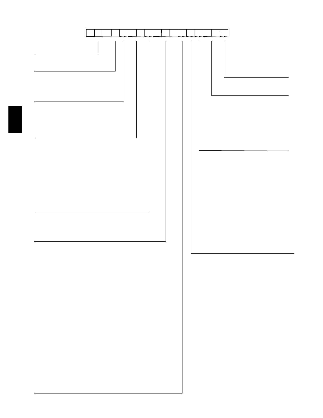
MODEL NUMBER NOMENCLATURE
1234567891011121314151617
5 8 0 J E 1 7 D 3 1 0 G 1 A 0 A A
__________ ______ ________ ______
Unit Type
580 = Gas Heat RTU
Model
J(PuronR Refrigerant) Packaging
Voltage
E = 4 6 0 --- 3 --- 6 0 Factory Installed Options
P = 208/230---3--- 60 0A = None
T = 5 7 5 --- 3 --- 6 0
Cooling Tons A=None
17 = 15 Ton B=Tempeconow/barorelief
580J
20 = 17.5 Ton D=Tempeconow/PE(cent)
24 = 20 Ton H = Enthalpy econo w/ b aro relief
28 = 25 Ton J=Enthalpyeconow/PE(cent)
Refrig. System/Gas Heat Options Q = 2 Position damper
D = 2 --- S t a g e C o m p r e s s o r w / A l u m i n u m g a s h e a t
exchanger Indoor Fan Options
F = 2---Stage Compressor w/Stainless steel gas heat 1 = Standard static option, Vertical
exchanger 2 = Medium static option, Vertical
K = Two Stage C ooling with Aluminum gas heat exchanger 3 = High static option, Vertical
and Perfect Humidity. (only available on RTPF coil B = Medium Static High Eff Motor/Vertical Supply,
models) Return Air Flow
M = Two Stage Cooling with Sainless Steel gas heat C = High Static High Eff Motor/Vertical Supply
exchanger and Perfect Humidity. (only available on Return Air Flow
RTPF coil models)
Heat Level Input 6 = Medium Static option, Horizontal
220 = 220,000 7 = High Static option, Horizontal
310 = 310,000 F = Medium Static High Eff Motor/Horizontal Supply,
400 = 400,000 Return Air Flow
N o v a t i o n C o i l O n l y ( O u t d o o r --- I n d o o r --- H a i l G u a r d ) Return Air Flow
G = Al/Al --- Al/Cu
H = Al/Al --- Cu/Cu
J = A l / A l --- E --- c o a t A l / C u
K = E --- c o a t A l / A l --- A l / C u
L = E --- c o a t A l / A l --- E --- c o a t A l / C u
T = Al/Al --- Al/Cu, Louvered Hail Guards
U = Al/Al --- Cu/Cu, Louvered Hail Guards
V = A l / A l --- E --- c o a t A l/ C u , L o u v e r e d H a i l G u a r d s
W = E --- c o a t A l / A l --- A l / C u , L o u v e r e d H a i l G u a r d s
X = E --- c o a t A l / A l --- E --- c o a t A l / C u , L o u v e r e d H a i l G u a r d s
R o u n d T u b e P l a t e F i n C o i l O p t i o n s ( O u t d o o r --- I n d o o r --- H a i l G u a r d )
A = Al/Cu --- Al/Cu
B = P r e c o a t A l / C u --- A l / C u
C = E --- c o a t A l / C u --- A l / C u
D = E --- c o a t A l / C u --- E --- c o a t A l / C u
E = C u / C u --- A l / C u
F = Cu/Cu --- Cu/Cu
M = A l / C u --- A l / C u --- L o u v e r e d H a i l G u a r d s
N = P r e c o a t A l / C u --- A l / C u --- L o u v e r e d H a i l G u a r d s
P = E --- c o a t A l / C u --- A l / C u --- L o u v e r e d H a i l G u a r d s
Q = E --- c o a t A l / C u --- E --- c o a t A l/ C u --- L o u v e r e d H a i l G u a r d s
R = C u / C u --- A l / C u --- L o u v e r e d H a i l G u a r d s
S = C u / C u --- C u / C u --- L o u v e r e d H a i l G u a r d s
A=Standard
Outdoor Air Options
P = Manual outdoor air damper
5 = Standard Static option, Horizontal
G = High Static High Eff Motor/Horizontal Supply,
4
Page 5
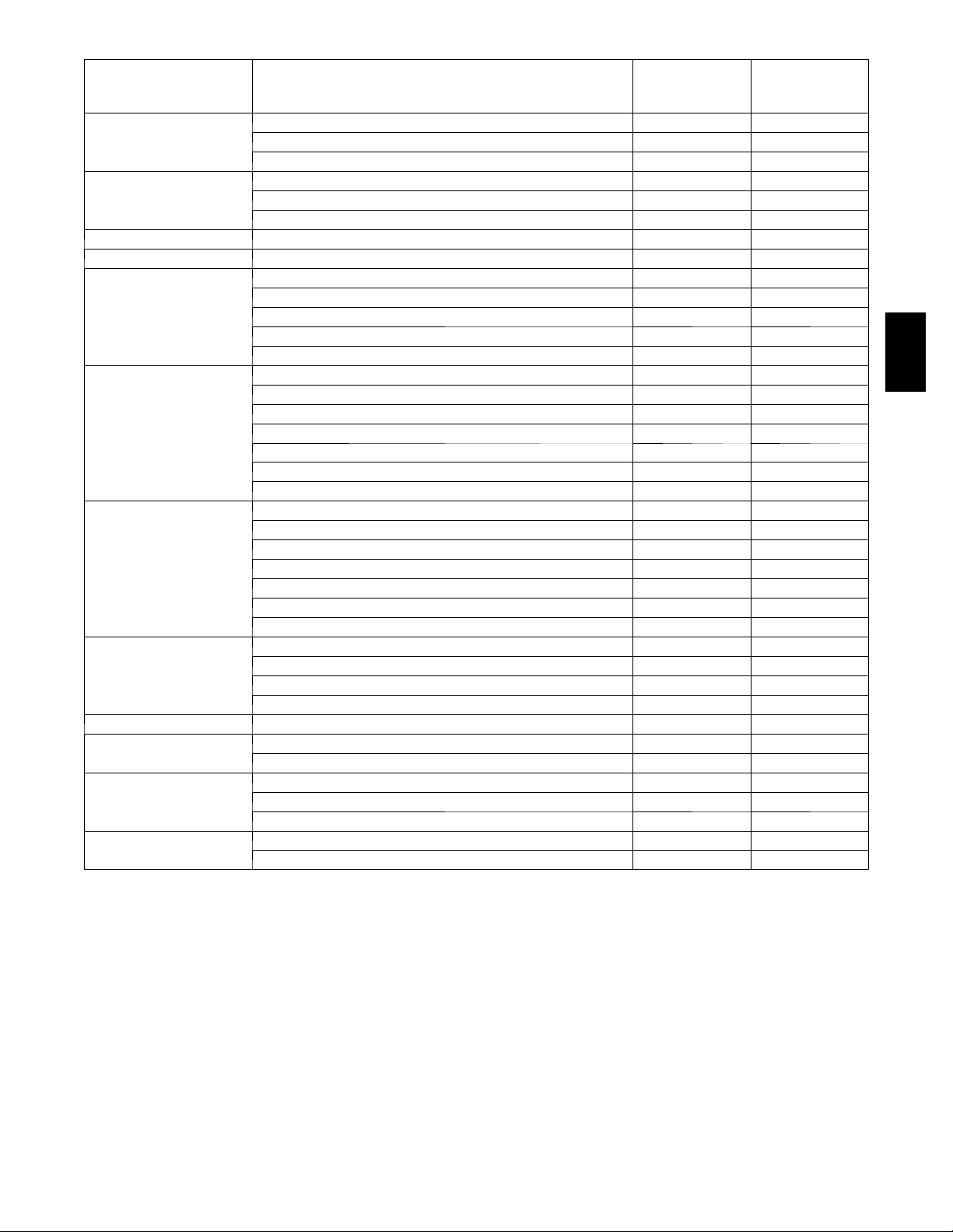
Table 1 – FACTORY--INST ALLED OPTIONS AND FIELD--INSTALLED ACCESSORIES
FACTORY
CATEGORY ITEM
Dedicated Vertical Air Flow Duct Configuration X
Cabinet
Dedicated Horizontal Air Flow Duct Configuration X
Thru--- the---base electrical or gas--- line connections X
Cu/Cu (indoor) coils X
Coil Options
Pre---Coat (outdoor) coils X
E ---coated (outdoor & indoor) coils X
Humidity Control Perfect Humidity™ Dehumidification System X
Condenser Protection Condenser coil hail guard (louvered design) X X
Thermostats, temperature sensors, and subbases X
RTU Open protocol controller X
Controls
Smoke detector (supply and/or return air) X X
Time Guard II compressor delay control circuit X
Phase Monitor X
EconoMi$ert IV (for electro---mechanical controlled RTUs) X X
EconoMi$ert2 (for DDC controlled RTUs) X X
Economizers
& Outdoor Air
Dampers
Motorized 2 position outdoor---air damper X X
Manual outdoor---air damper (25%) X X
Barometric relief
1
Barometric hood (Horizontal economizer) X
Power exhaust–centrifugal blower X X
2
2
2
Economizer Sensors
&
IAQ Devices
Single dry bulb temperature sensors
Differential dry bulb temperature sensors
Single enthalpy sensors
Differential enthalpy sensors
2
2
Wall or duct mounted CO2sensor
Unit mounted CO2sensor
2
4---in Filter Track Assembly X
Propane conversion kit X
Gas Heat
Stainless steel heat exchanger X
High altitude conversion kit X
Flue Discharge Deflector X
Indoor Motor & Drive Multiple motor and drive packages X
Low Ambient
Control
Power
Options
Roof Curbs
Winter start kit
Motormaster head pressure controller
Convenience outlet (powered) X
Convenience outlet (unpowered) X
Non ---fused disconnect
Roof curb 14 ---in (356mm) X
Roof curb 24 ---in (610mm) X
3
3
4
INSTALLED
OPTION
X X
X X
X X
X
X
INSTALLED
ACCESSORY
FIELD
580J
X
X
X
X
X
NOTES:
1. Included with economizer.
2. Sensors used to optimize economizer performance.
3. See application data for assistance.
4. Non -- -fused disconnect switch cannot be used when MOCP electrical rating exceeds 70 amps at 460/575 volt and 150
amps at 208/230 volt. Bryant Packaged RTUBuilder selects this automatically.
5
Page 6

FACTORY OPTIONS AND/OR ACCESSORIES
Economizer (dry--bulb or enthalpy)
Economizers save money. They bring in fresh, outside air
for ventilation; and provide cool, outside air to cool your
building. This is the preferred method of low--ambient
cooling. When coupled to CO
provide even more savings by coupling the ventilation air
to only that amount required.
Economizers are available, installed and tested by the
factory, with either enthalpy or dry--bulb temperature
inputs. There are also models for electromechanical as
well as direct digi tal controllers. Addit ional sensors are
available as accessories to optimize the economizers.
Economizers include gravity controlled, barometric relief
equalizes building pressure and ambient air pressures.
580J
This can be a cast effective solution to prevent building
pressurization. If further control of exha ust air is required,
a dual centrifugal fan power exhaust system is also
available.
sensors, economizers can
2
CO2Sensor
Improves productivity and saves money by working with
the economizer to intake only the correct amount of
outside air for ventilation. As occupants fill your building,
the CO
CO
When the occupants leave, the CO
the sensor appropriately closes the economizer. This
intelligent control of the ventilation air, called Demand
Control Ventilation (DCV) reduces the overall load on the
rooftop, savi ng money.
sensor detects their presence through increasing
2
levels, and opens the economizer a ppropriately.
2
levels decrease, and
2
Smoke Detectors
Non--Fused Disconnect
This OSHA--compliant, factory--installed, safety switch
allows a service technician to locally secure power to the
rooftop.
Power Exhaust with Barometric Relief
Superior internal building pressure control. This
field--installed accessory or factory--installed option may
eliminate the need for costly, external pressure control
fans.
RTU Open Protocol Controller
Connect the rooftop to an existing BAS without needing
complicated translators or adapter modules using the RTU
Open controller. This new controller speaks the 4 most
common building a utomation system languages (Bacnet,
Modbus, N2, and Lonworks). Use this controller when
you have an existing BAS.
Time Guard II Control Circuit
This accessory protects your compressor by preventing
short--cycli ng in the event of some other fail ure, prevents
the compressor from restarting for 30 seconds after
stopping. Not required with RTU Open or authorized
commercial thermostats.
Motorized 2--Position Damper
The new Bryant 2--position, motorized outdoor air damper
admits up to 100% outside air. Using reliable, gear--driven
technology, the 2--position damper opens to allow
ventilation air and closes when the rooftop stops, stopping
unwanted infiltration.
Trust the experts. Smoke detectors make your application
safer and your job easier. Bryant smoke detectors
immediately shut down the rooftop unit when smoke is
detected. They are available, installed by the factory, for
supply air, return air, or both.
Louvered Hail Guards
Sleek, louvered panels protect the condenser coil from
hail damage, foreign objects, and incidental contact.
Convenience Outlet (powered or un--powered)
Reduce service and/or installation costs by including a
convenience outlet in your specification. Bryant will
install this service feature at our factory. Provides a
convenient, 15 amp, 115v GFCI receptacle with “Wet in
Use” cover. The “powered” option allows the installer to
power the outlet from the line side of t he disconnect side
as required by code. The “unpowered” option is to be
powered from a separate 115/120v power source.
Manual OA Damper
Manual outdoor air dampers are an economical way to
bring in ventilation air. The dampers are available in 25%
versions.
Optional P erfect Humidityt Adaptive
Dehumidification System
Bryant’s Perfect Humidity adaptive dehumidification
system is an all--inclusive factory installed option that can
be ordered with any Legacy Line 580J17--28 rooftop unit.
This system expands the envelope of operation of Bryant’s
Legacy Line rooftop products to provide unprecedented
flexibility to meet year round comfort conditions.
The Perfect Humidity adaptive dehumidification system
has the industry’s only dual dehumidification mode
setting. The Perfect Humidity system includes two new
modes of operation.
6
Page 7

FACTORY OPTIONS AND/OR ACCESSORIES (cont.)
The Legac y Line 580J17--28 rooftop coupled with the
Perfect Humidityt system is capable of operating in
normal design cooling mode, subcooling mode, and hot
gas reheat mode. Normal design cooling mode is when the
unit will operate under its normal sequence of operation
by cycling compressors to maintain comfort conditions.
Subcooling mode will operate to satisfy part load type
conditions when the space requires combined sensible and
a higher proportion of latent load control. Hot Gas Reheat
mode will operate when outdoor temperatures diminish
and the need for latent capacity is required for sole
humidity control. Hot Gas Reheat mode will provide
neutral air for maximum dehumidification operation.
Optional Stainless Steel Heat Exchanger
The stainless steel heat exchanger option provides the
tubular heat exchanger be made out of a minimum 20
gauge type 409 stainless steel for applications where the
mixed air to the heat exchanger is expected to drop below
45_F(7_C). Stainless steel may be specified on
applications where the presence of airborne contaminants
require its use (applications such as paper mills) or in area
with very high outdoor humidity that may result in severe
condensation in the heat excha nger during cooling
operation.
Flue Discharge Deflector
Motormaster Head Pressure Controller
The Motormaster motor controller is a low ambient, head
pressure controller kit that is designed to maintain the
unit’s condenser head pressure during periods of low
ambient cooling operation. This devi ce should be used as
an alternative to economizer free cooling not when
economizer usage is either not appropriate or desired. The
Motormaster will either cycle the outdoor--fan motors or
operate them at reduced speed to maintain the unit
operation, depending on the model.
Winter Start Kit
The winter start kit by Bryant extends the low ambient
limit of your rooftop to 25_F(--4_C). The kit bypasses the
low pressure switch, preventi ng nuisance tripping of the
low pressure switch. Other low ambient precautions may
still be prudent.
Propane Heating
Convert your gas heat rooftop from standard natural gas
operation to Propane using this field--installed kit.
High Altitude Heating
High altitudes have less oxygen, which means heat
exchangers need less fuel. The new gas orifices in this
field--installed kit make the necessary adjustment for high
altitude applications. They restore the optimal fuel to air
mixture and maintain healthy combustion at altitudes
above 2000 ft (610m). Kits may not be required in all
areas.
The flue discharge deflector is a useful accessory when
flue gas recirculation is a concern. By venting the flue
discharge upwards, the deflector minimizes the chance for
a neighboring unit to intake the flue exhaust.
Alternate Motors and Drives
Some applications need larger horsepower motors, some
need more airflow, and some need both. Regardless of the
case, your Bryant expert has a factory installe d
combination to meet your application. A wide selection of
motors and pulleys (drives) are available, factory
installed, to handle nearly any application.
Thru--the--Base Connections
Thru--the--base connections, available as a factory option,
are necessary to ensure proper connection and seal when
routing wire and piping through the rooftop’s basepan and
curb. These couplings eliminate roof penetration and
should be considered for gas lines, main power lines, as
well as control power.
Barometric Hood
For Horizontal Economizer applications where relief
damper is installed in duct work. This kit provides the
needed protection.
580J
7
Page 8
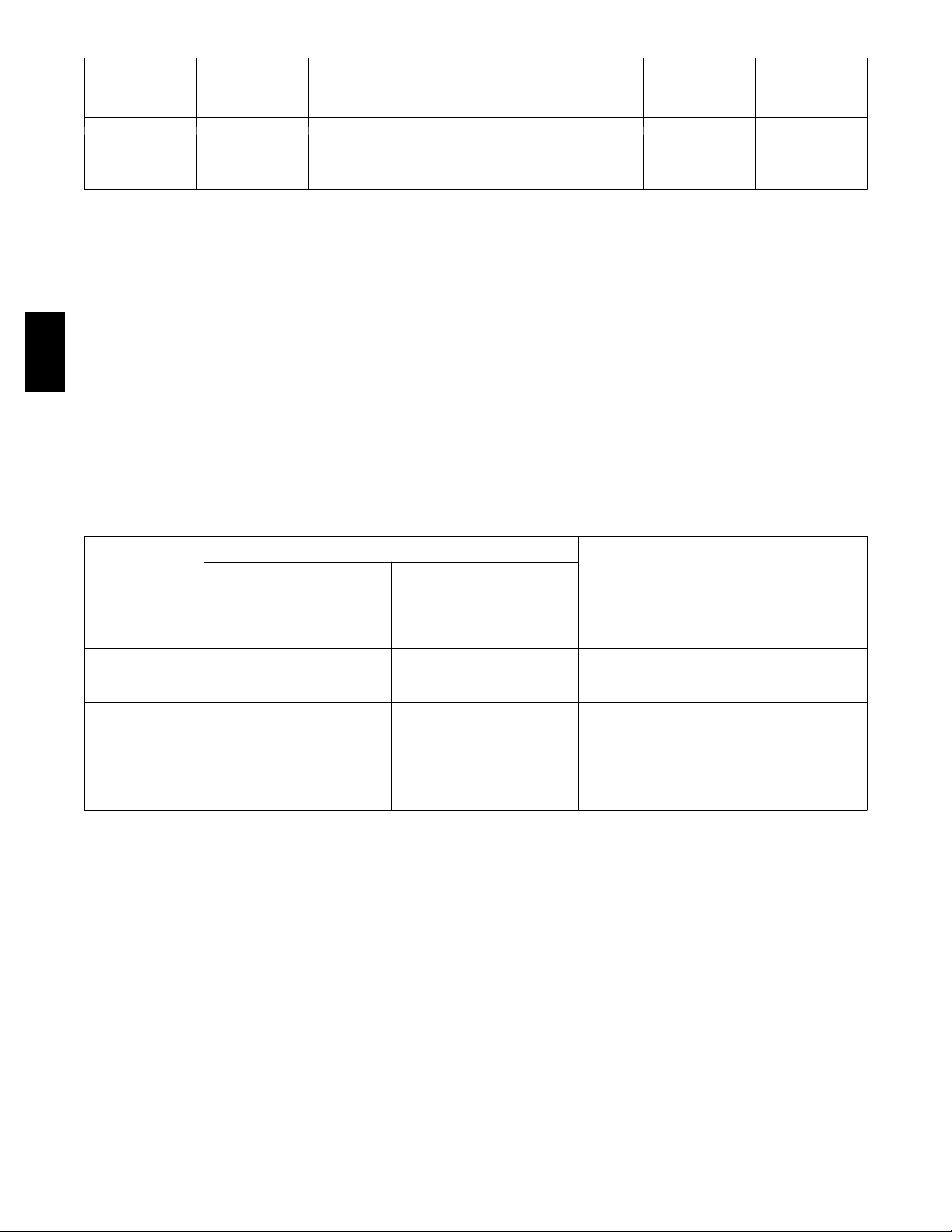
Table 2 – AHRI COOLING RATING TABLE 2--STAGE COOLING
UNIT
17 2 15 192.0 18.7 10.8 12.0
20 2 17.5 208.0 19.3 10.8 11.9
24 2 20 242.0 24.7 9.8 10.8
28 2 25 282.0 28.8 9.8 10.4
COOLING
STAGES
NOM.
CAPACITY
(TONS)
NET
COOLING
CAPACITY
(MBH)
TOTAL POWER
(kW)
EER IEER
LEGEND
AHRI --- Air Conditioning, Heating and Refrigeration
Institute Test Standard
ASHRAE --- American Society of Heating, Refrigerating
and Air Conditioning, Inc.
EER --- Energy Efficiency Ratio
IEER --- Integrated Energy Efficiency Ratio
580J
Table 3 – HEATING RATING T ABLE -- NATURAL GAS & PROPANE
MODEL
SIZE
17
20
24
28
HEAT
SIZE
LOW 176 / 142 220 / 178 20 --- 55 81%
MED 248 / 200 310 / 251 30 --- 60 81%
HIGH 320 / 260 400 / 324 35 --- 65 81%
LOW 176 / 142 220 / 178 15 --- 55 81%
MED 248 / 200 310 / 251 25 --- 60 81%
HIGH 320 / 260 400 / 324 30--- 65 81%
LOW 176 / 142 220 / 178 15 --- 55 81%
MED 248 / 200 310 / 251 20 --- 60 81%
HIGH 320 / 260 400 / 324 30--- 65 81%
LOW 176 / 142 220 / 178 10 --- 55 81%
MED 248 / 200 310 / 251 15 --- 60 81%
HIGH 320 / 260 400 / 324 20 --- 65 81%
INPUT / OUTPUT
STAGE 1 (MBH)
NOTES:
Heat ratings are for natural gas heat exchangers operated at or below 2000 ft (610 m). For information on Propane or altitudes above 2000 ft (610 m), see the Application Data section of this book. Accessory Propane/High Altitude kits are also
available.
AL/SS HEAT EXCHANGER
INPUT / OUTPUT
STAGE 2 (MBH)
NOTES:
1. Rated and certified under AHRI Standard 340/360, as
appropriate.
2. Ratings are based on:
Cooling Standard: 80_F(27_C) db, 67_F(19_C) wb
indoor air temp and 95_F(35_C) db outdoor air temp.
IEER Standard: A measure that expresses cooling
part---load EER efficiency for commercial unitary air
conditioning and heat pump equipment on the basis of
weighted operation at various load capacities.
3. All 580J units comply with ASHRAE 90.1 Energy
Standard for minimum EER and IEER requirements.
4. 580J units comply with US Energy Policy Act (2005).
To evaluate code compliance requirements, refer to
state and local codes or visit the following website:
http://bcap -- -energy.org to determine if compliance
with this standard pertains to your state, territory, or
municipality.
TEMP RISE
(DEG F)
THERMAL
EFFICIENCY
(%)
In the USA the input rating for altitudes above 2000 ft (610m) must be derated by 4% for each 1000 ft (305 m) above sea
level. In Canada, the input rating must be derated by 10% for altitudes of 2000 ft (610 m) to 4500 ft (1372 m) above sea level.
8
Page 9
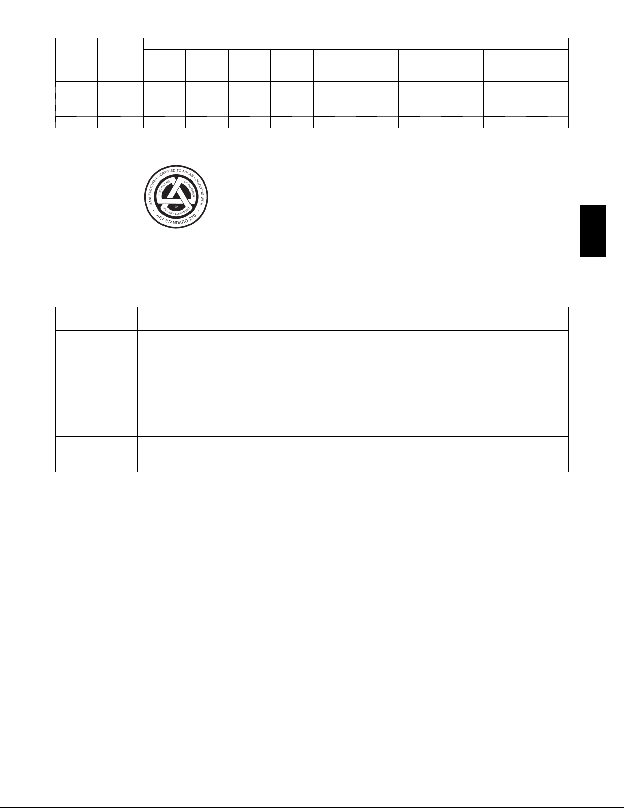
Table 4 – SOUND PERFORMANCE T ABLE
Outdoor Sound (dB)
MODEL
SIZE
LEGEND
dB --- Decibel
COOLING
STAGES
17 2 84.1 84 92.2 83.9 80.4 81.8 78.7 76.5 72.2 65.4
20 2 84.1 84 92.2 83.9 80.4 81.8 78.7 76.5 72.2 65.4
24 2 86.5 87 95.6 87.5 84.2 84.2 81.7 77.9 73.2 66.3
28 2 85.9 86 97.1 88.3 84.4 83.3 80.7 77.4 73.4 67.3
A --- W t g .
AHRI
370
Rating
63 125 250 500 1000 2000 4000 8000
NOTES:
1. Outdoor sound data is measure in accordance with
AHRI standard 270 ---2008.
2. Measurements are expressed in terms of sound power.
Do not compare these values to sound pressure values
because sound pressure depends on specific environmental factors which normally do not match individual
applications. Sound power values are independent of
the environment and therefore more accurate.
3. A ---weighted sound ratings filter out very high and very
low frequencies, to better approximate the response of
“average” human ear. A -- -weighted measurements for
Bryant units are taken in accordance with AHRI standard 270 ---2008.
Table 5 – MINIMUM -- MAXIMUM AIRFLOW RATINGS -- NATURAL GAS & PROPANE
MODEL
SIZE
17
20
24
28
HEAT
SIZE
LOW
MED 3880 7750 3880 7750
HIGH 4620 8570 4620 8570
LOW
MED 3880 9300 3880 9300
HIGH 4620 10000 4620 10000
LOW
MED 3880 11630 3880 11630
HIGH 4620 10000 4620 10000
LOW
MED 3880 15500 3880 15500
HIGH 4620 15000 4620 15000
MINIMUM MAXIMUM MINIMUM MAXIMUM MINIMUM MAXIMUM
COOLING AL HX HEATING S S HX HEATING
2960 8150 2960 8150
4500 7500
2960 10860 2960 10860
5250 9000
2960 10860 2960 10860
6000 10000
2960 16300 2960 16300
7500 12500
580J
9
Page 10

Table 6 – PHYSICAL DATA (COOLING) 15 -- 25 TONS Novation -- All Aluminum Coil Design
580J*17 580J*20 580J*24 580J*28
Refrigeration System
# Circuits / # Comp. / Type 2/2/Scroll 2/2/Scroll 2/2/Scroll 2/2/Scroll
R--- 410a charge A/B (lbs) 9.5/12.0 9.5/12.0 14.4/12.5 12.5/13.0
Metering device Acutrol Acutrol Acutrol Acutrol
High---press. Trip / Reset (psig) 630 / 505 630 / 505 630 / 505 630 / 505
Low--- press. Trip / Reset (psig) 54 / 117 54 / 117 54 / 117 54 / 117
Compressor Capacity Staging (%) 50 / 100 50 / 100 50 / 100 50 / 100
Evap. Coil
Material Cu / Al Cu / Al Cu / Al Cu / Al
Tube Diameter 3 / 8 --- i n 3/ 8 --- i n 3/ 8 --- i n 3 / 8 --- i n
Rows / FPI 4/15 4/15 4/15 4/15
Tota l fa c e a r e a ( f t 2) 19.56 19.56 22.00 23.11
Condensate drain conn. size 3 / 4 --- i n 3 / 4 --- i n 3 / 4 --- i n 3 / 4 --- i n
Evap. fan and motor
VERTICAL
580J
Motor Qty / Drive type 1/Belt 1/Belt 1/Belt 1/Belt
Max BHP 2.2 3.3 4.9 4.9
RPM range 514--- 680 622--- 822 690---863 717---911
Motor frame size 56 56 56 56
Standard Static
Medium Static
Fan Qty / Type 2/Centrifugal 2/Centrifugal 2/Centrifugal 2/Centrifugal
Fan Diameter (in) 15 x 15 15 x 15 15 x 15 15 x 15
Motor Qty / Drive type 1/Belt 1/Belt 1/Belt 1/Belt
Max BHP 3.3 4.9 6.5 6.5
RPM range 679--- 863 713--- 879 835 --- 1021 913 --- 1116
Motor frame size 56 56 184T 184T
Fan Qty / Type 2/Centrifugal 2/Centrifugal 2/Centrifugal 2/Centrifugal
Fan Diameter (in) 15 x 15 15 x 15 15 x 15 15 x 15
Motor Qty / Drive type 1/Belt 1/Belt 1/Belt 1/Belt
Max BHP 4.9 6.5 8.7 8.7
RPM range 826--- 1009 882--- 1078 941 --- 1176 941 ---1176
Motor frame size 56 184T 213T 213T
High Static
High Eff*
Medium Static
High Eff*
High Static
Fan Qty / Type 2/Centrifugal 2/Centrifugal 2/Centrifugal 2/Centrifugal
Fan Diameter (in) 15 x 15 15 x 15 15 x 15 15 x 15
Motor Qty / Drive type
Max BHP
RPM range
Motor frame size
Fan Qty / Type
Fan Diameter (in)
Motor Qty / Drive type
Max BHP
RPM range
Motor frame size
Fan Qty / Type
Fan Diameter (in)
n/a n/a 1/Belt 1/Belt
n/a n/a 6.5 6.5
n/a n/a 835--- 1021 913 ---1116
n/a n/a 184T 184T
n/a n/a 2/Centrifugal 2/Centrifugal
n/a n/a 15 x 15 15 x 15
n/a 1/Belt 1/Belt 1/Belt
n/a 6.5 8.7 8.7
n/a 882---1078 941---1176 941---1176
n/a 184T 213T 213T
n/a 2/Centrifugal 2/Centrifugal 2/Centrifugal
n/a 15 x 15 15 x 15 15 x 15
* Section 313 of the Energy Independence and Security Act of 2007 (EISA 2007) mandates that the efficiency of general purpose motors we use in our Light
Commercial Rooftops rated at 5.0 HP and larger be increased on or after December 19, 2010. We will offer both high and standard efficient motors u ntil
inventory is depleted and then shift over solely to the high efficient motors only.
10
Page 11

Table 6 – PHYSICAL DATA (con’t) (COOLING) 15 -- 25 TONS Novation -- All Aluminum
Coil Design
580J*17 580J*20 580J*24 580J*28
HORIZONTAL
Motor Qty / Drive type 1/Belt 1/Belt 1/Belt 1/Belt
Max BHP 2.2 3.3 4.9 4.9
RPM range 514--- 680 622--- 822 690---863 647---791
Motor frame size 56 56 56 56
Standard Static
Medium Static
High Static
Fan Qty / Type 2/Centrifugal 2/Centrifugal 2/Centrifugal 2/Centrifugal
Fan Diameter (in) 18 x 15 & 15 X 11 18 x 15 & 15 X 11 18 x 15 & 15 X 11 18 x 15 & 15 X 11
Motor Qty / Drive type 1/Belt 1/Belt 1/Belt 1/Belt
Max BHP 3.3 4.9 6.5 6.5
RPM range 614--- 780 713--- 879 835 --- 1021 755--- 923
Motor frame size 56 56 184T 184T
Fan Qty / Type 2/Centrifugal 2/Centrifugal 2/Centrifugal 2/Centrifugal
Fan Diameter (in) 18 x 15 & 15 X 11 18 x 15 & 15 X 11 18 x 15 & 15 X 11 18 x 15 & 15 X 11
Motor Qty / Drive type 1/Belt 1/Belt 1/Belt 1/Belt
Max BHP 4.9 6.5 8.7 8.7
RPM range 746--- 912 882 --- 1078 941 --- 1176 827 ---1010
Motor frame size 56 184T 213T 213T
Fan Qty / Type 2/Centrifugal 2/Centrifugal 2/Centrifugal 2/Centrifugal
Fan Diameter (in) 18 x 15 & 15 X 11 18 x 15 & 15 X 11 18 x 15 & 15 X 11 18 x 15 & 15 X 11
580J
Motor Qty / Drive type
High Eff*
Medium Static
High Eff*
High Static
Cond. Coil (Circuit A)
Cond. Coil (Circuit B)
Cond. fan / motor
Motor frame size
Fan Diameter (in)
Motor Qty / Drive type
Motor frame size
Fan Diameter (in)
Total face area (ft2) 21.4 21.4 25.1 27.1
Total face area (ft2) 21.4 21.4 17.4 27.1
Qty / Motor drive type 3 / direct 3/direct 4/direct 4/direct
Fan diameter (in) 22 22 22 22
n/a n/a 1/Belt 1/Belt
Max BHP
RPM range
Fan Qty / Type
Max BHP
RPM range
Fan Qty / Type
Coil type Novation Novation Novation Novation
Coil Length (in) 70 70 82 75
Coil Height (in) 44 44 44 52
Coil type Novation Novation Novation Novation
Coil Length (in) 70 70 57 75
Coil Height (in) 44 44 44 52
Motor HP / RPM 1/4 / 1100 1/4 / 1100 1/4 / 1100 1/4 / 1100
n/a n/a 6.5 6.5
n/a n/a 835--- 1021 755--- 923
n/a n/a 184T 184T
n/a n/a 2/Centrifugal 2/Centrifugal
n/a n/a 18 x 15/15 x 11 18 x 15/15 x 11
n/a 1/Belt 1/Belt 1/Belt
n/a 6.5 8.7 8.7
n/a 882---1078 941---1176 827---1010
n/a 184T 213T 213T
n/a 2/Centrifugal 2/Centrifugal 2/Centrifugal
n/a 18 x 15/15 x 11 18 x 15/15 x 11 18 x 15/15 x 11
Filters
RAFilter#/size(in) 6/20x25x2 6/20x25x2 6/20x25x2 9/16x25x2
OA inlet screen # / size (in) 4/16x25x1 4/16x25x1 4/16x25x1 4/16x25x1
* Section 313 of the Energy Independence and Security Act of 2007 (EISA 2007) mandates that the efficiency of general purpose motors we use in our Light
Commercial Rooftops rated at 5.0 HP and larger be increased on or after December 19, 2010. We will offer both high and standard efficient motors u ntil
inventory is depleted and then shift over solely to the high efficient motors only.
11
Page 12

Table 7 – PHYSICAL DATA (COOLING) 15 -- 25 TONS RTPF -- Round Tube/Plate Fin Coil Design
580J*17 580J*20 580J*24 580J*28
Refrigeration System
# Circuits / # Comp. / Type 2/2/Scroll 2/2/Scroll 2/2/Scroll 2/2/Scroll
R--- 410a charge A/B (lbs) 16.3/17.5 9.5/12.0 20.6/14.7 19.8/20.4
Perfect Humidity R--- 410a charge A/B (lbs) 25.9/25.7 25.9/25.7 27.9/20.5 27.9/28.9
Metering device Acutrol Acutrol Acutrol Acutrol
High---press. Trip / Reset (psig) 630 / 505 630 / 505 630 / 505 630 / 505
Low--- press. Trip / Reset (psig) 54 / 117 54 / 117 54 / 117 54 / 117
Perfect Humidity Low--- press. Trip / Reset (psig) 27 / 44 27 / 44 27 / 44 27 / 44
Compressor Capacity Staging (%) 50 / 100 50 / 100 50 / 100 50 / 100
Evap. Coil
Material Cu / Al Cu / Al Cu / Al Cu / Al
Tube Diameter 3 / 8 --- i n 3 / 8 --- i n 3 / 8 --- i n 3 / 8 --- i n
Rows / FPI 4/15 4/15 4/15 4/15
Tota l fa c e a r e a ( f t 2) 22.00 22.00 22.00 23.11
Condensate drain conn. size 3 / 4 --- i n 3 / 4 --- i n 3 / 4 --- i n 3 / 4 --- i n
Perfect Humidity Coil
580J
Material Cu / Al Cu / Al Cu / Al Cu / Al
Tube Diameter 3 / 8 --- i n 3 / 8 --- i n 3 / 8 --- i n 3 / 8 --- i n
Rows / FPI 1/17 1/17 1/17 1/17
Tota l fa c e a r e a ( f t 2) 22.00 22.00 22.00 23.11
Evap. fan and motor
VERTICAL
Motor Qty / Drive type 1/Belt 1/Belt 1/Belt 1/Belt
Max BHP 2.2 3.3 4.9 4.9
RPM range 514 --- 680 622 --- 822 690 --- 863 717 --- 911
Motor frame size 56 56 56 56
Standard Static
Medium Static
High Static
High Eff*
Medium Static
Fan Qty / Type 2/Centrifugal 2/Centrifugal 2/Centrifugal 2/Centrifugal
Fan Diameter (in) 15 x 15 15 x 15 15 x 15 15 x 15
Motor Qty / Drive type 1/Belt 1/Belt 1/Belt 1/Belt
Max BHP 3.3 4.9 6.5 6.5
RPM range 679 --- 863 713 --- 879 835--- 1021 913 --- 1116
Motor frame size 56 56 184T 184T
Fan Qty / Type 2/Centrifugal 2/Centrifugal 2/Centrifugal 2/Centrifugal
Fan Diameter (in) 15 x 15 15 x 15 15 x 15 15 x 15
Motor Qty / Drive type 1/Belt 1/Belt 1/Belt 1/Belt
Max BHP 4.9 6.5 8.7 8.7
RPM range 826 --- 1009 882 --- 1078 941 ---1176 941 ---1176
Motor frame size 56 56 213T 213T
Fan Qty / Type 2/Centrifugal 2/Centrifugal 2/Centrifugal 2/Centrifugal
Fan Diameter (in) 15 x 15 15 x 15 15 x 15 15 x 15
Motor Qty / Drive type
Max BHP
RPM range
Motor frame size
Fan Qty / Type
Fan Diameter (in)
n/a n/a 1/Belt 1/Belt
n/a n/a 6.5 6.5
n/a n/a 835--- 1021 913 ---1116
n/a n/a 184T 184T
n/a n/a 2/Centrifugal 2/Centrifugal
n/a n/a 15 x 15 15 x 15
Motor Qty / Drive type
Max BHP
RPM range
High Eff*
High Static
Motor frame size
Fan Qty / Type
Fan Diameter (in)
n/a 1/Belt 1/Belt 1/Belt
n/a 6.5 8.7 8.7
n/a 882---1078 941---1176 941---1176
n/a 184T 213T 213T
n/a 2/Centrifugal 2/Centrifugal 2/Centrifugal
n/a 15 x 15 15 x 15 15 x 15
* Section 313 of the Energy Independence and Security Act of 2007 (EISA 2007) mandates that the efficiency of general purpose motors we use in our Light
Commercial Rooftops rated at 5.0 HP and larger be increased on or after December 19, 2010. We will offer both high and standard efficient motors u ntil
inventory is depleted and then shift over solely to the high efficient motors only.
12
Page 13
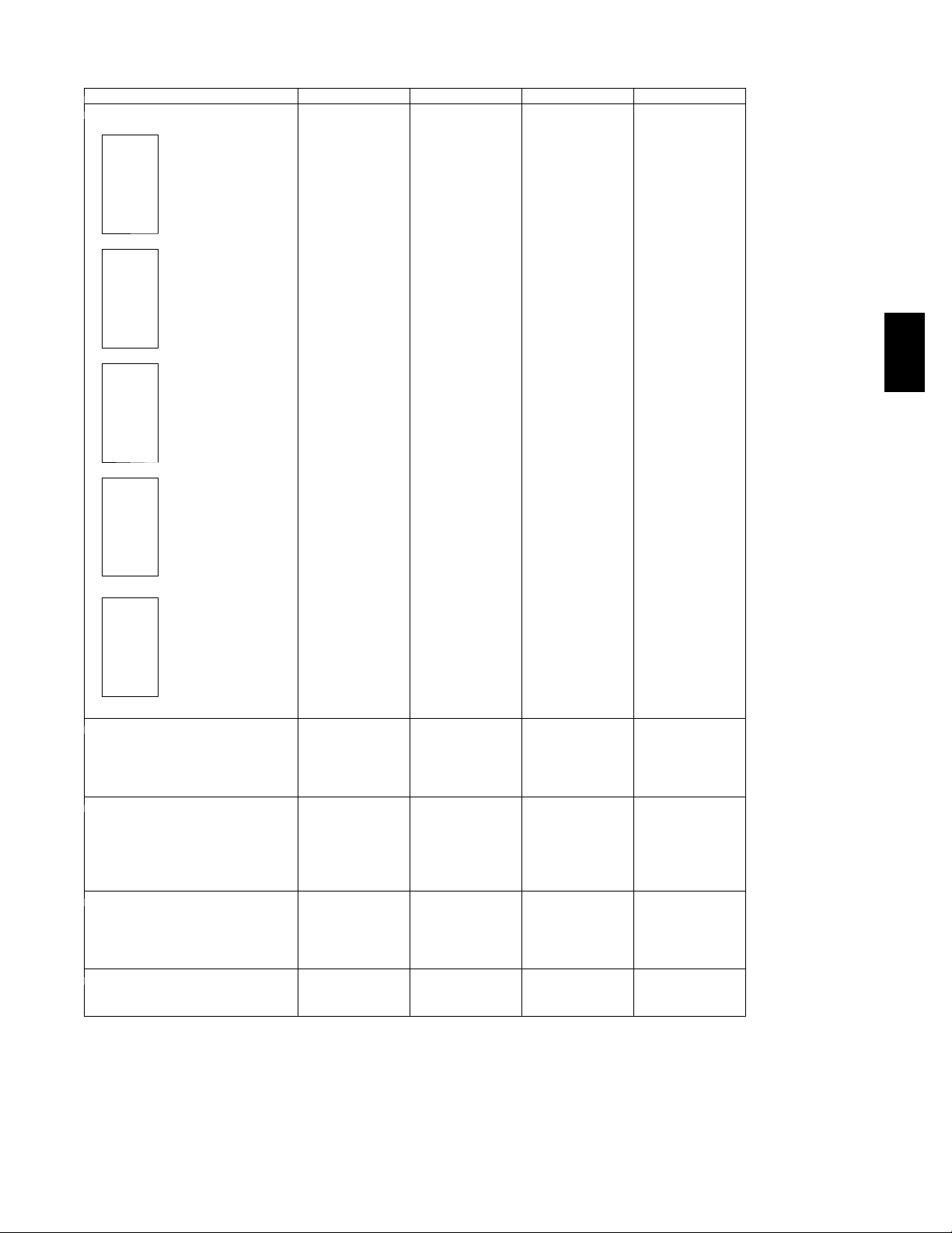
Table 7 – PHYSICAL DATA (con’t) (COOLING) 15 -- 25 TONS RTPF -- Round Tube/Plate
Fin Coil Design
580J*17 580J*20 580J*24 580J*28
HORIZONTAL
Motor Qty / Drive type 1/Belt 1/Belt 1/Belt 1/Belt
Max BHP 2.2 3.3 4.9 4.9
RPM range 514--- 680 622--- 822 690---863 647---791
Motor frame size 56 56 56 56
Standard Static
Medium Static
High Static
Fan Qty / Type 2/Centrifugal 2/Centrifugal 2/Centrifugal 2/Centrifugal
Fan Diameter (in) 18 x 15 & 15 X 11 18 x 15 & 15 X 11 18 x 15 & 15 X 11 18 x 15 & 15 X 11
Motor Qty / Drive type 1/Belt 1/Belt 1/Belt 1/Belt
Max BHP 3.3 4.9 6.5 6.5
RPM range 614--- 780 713--- 879 835 --- 1021 755--- 923
Motor frame size 56 56 184T 184T
Fan Qty / Type 2/Centrifugal 2/Centrifugal 2/Centrifugal 2/Centrifugal
Fan Diameter (in) 18 x 15 & 15 X 11 18 x 15 & 15 X 11 18 x 15 & 15 X 11 18 x 15 & 15 X 11
Motor Qty / Drive type 1/Belt 1/Belt 1/Belt 1/Belt
Max BHP 4.9 6.5 8.7 8.7
RPM range 746--- 912 882 --- 1078 941 --- 1176 827 ---1010
Motor frame size 56 184T 213T 213T
Fan Qty / Type 2/Centrifugal 2/Centrifugal 2/Centrifugal 2/Centrifugal
Fan Diameter (in) 18 x 15 & 15 X 11 18 x 15 & 15 X 11 18 x 15 & 15 X 11 18 x 15 & 15 X 11
580J
Motor Qty / Drive type
High Eff*
Medium Static
High Eff*
High Static
Cond. Coil (Circuit A)
Cond. Coil (Circuit B)
Cond. fan / motor
Motor frame size
Fan Diameter (in)
Motor Qty / Drive type
Motor frame size
Fan Diameter (in)
Total face area (ft2) 21.4 21.4 25.1 27.1
Total face area (ft2) 21.4 21.4 17.4 27.1
Qty / Motor drive type 3 / direct 3/direct 4/direct 4/direct
Fan diameter (in) 22 22 22 22
n/a n/a 1/Belt 1/Belt
Max BHP
RPM range
Fan Qty / Type
Max BHP
RPM range
Fan Qty / Type
Coil type RTPF RTPF RTPF RTPF
Coil Length (in) 70 70 82 75
Coil Height (in) 44 44 44 52
Coil type RTPF RTPF RTPF RTPF
Coil Length (in) 70 70 57 75
Coil Height (in) 44 44 44 52
Motor HP / RPM 1/4 / 1100 1/4 / 1100 1/4 / 1100 1/4 / 1100
n/a n/a 6.5 6.5
n/a n/a 835--- 1021 755--- 923
n/a n/a 184T 184T
n/a n/a 2/Centrifugal 2/Centrifugal
n/a n/a 18 x 15/15 x 11 18 x 15/15 x 11
n/a 1/Belt 1/Belt 1/Belt
n/a 6.5 8.7 8.7
n/a 882---1078 941---1176 827---1010
n/a 184T 213T 213T
n/a 2/Centrifugal 2/Centrifugal 2/Centrifugal
n/a 18 x 15/15 x 11 18 x 15/15 x 11 18 x 15/15 x 11
Filters
RAFilter#/size(in) 6/20x25x2 6/20x25x2 6/20x25x2 9/16x25x2
OA inlet screen # / size (in) 4/16x25x1 4/16x25x1 4/16x25x1 4/16x25x1
* Section 313 of the Energy Independence and Security Act of 2007 (EISA 2007) mandates that the efficiency of general purpose motors we use in our Light
Commercial Rooftops rated at 5.0 HP and larger be increased on or after December 19, 2010. We will offer both high and standard efficient motors u ntil
inventory is depleted and then shift over solely to the high efficient motors only.
13
Page 14

Table 8 – PHYSICAL DATA (HEA TING) 15 -- 25 TONS
580J*D17 580J*D20 580J*D24 580J*D28
Gas Connection
#ofGasValves 1 1 1 1
Nat. gas supply line press (in. w.g.)/(PSIG) 5 --- 1 3 / 0 . 1 8 --- 0 . 4 7 5 --- 1 3 / 0 . 1 8 --- 0 . 4 7 5 --- 1 3 / 0 . 1 8 --- 0 . 4 7 5 --- 1 3 / 0 . 1 8 --- 0 . 4 7
Propane supply line press (in. w.g.)/(PSIG) 11--- 13 / 0.40 ---0.47 11 ---13 / 0.40---0.47 11 ---13 / 0.40 ---0.47 11---13 / 0.40---0.47
Heat Anticipator Setting (Amps)
1st stage 0.14 0.14 0.14 0.14
2nd stage 0.14 0.14 0.14 0.14
Natural Gas Heat
#ofstages/#ofburners(total) 2/5 2/5 2/5 2/5
Connection size 3 / 4 --- i n N P T 3 / 4 --- i n N P T 3 / 4 --- i n N P T 3 / 4 --- i n N P T
LOW
Rollout switch opens / closes 195 / 115 195 / 115 195 / 115 195 / 115
Temperatureriserange(F) 25 --- 55 25 --- 55 25 --- 55 25 --- 55
580J
MED
HIGH
Liquid Propane Heat
LOW
MED
HIGH
#ofstages/#ofburners(total) 2/7 2/7 2/7 2/7
Connection size 3 / 4 --- i n N P T 3 / 4 --- i n N P T 3 / 4 --- i n N P T 3 / 4 --- i n N P T
Rollout switch opens / closes 195 / 115 195 / 115 195 / 115 195 / 115
Temperatureriserange(F) 30--- 60 30--- 60 30 --- 60 30--- 60
#ofstages/#ofburners(total) 2/10 2/10 2/10 2/10
Connection size 3 / 4 --- i n N P T 3 / 4 --- i n N P T 3 / 4 --- i n N P T 3 / 4 --- i n N P T
Rollout switch opens / closes 195 / 115 195 / 115 195 / 115 195 / 115
Temperatureriserange(F) 35--- 65 35--- 65 35 --- 65 35--- 65
#ofstages/#ofburners(total) 2/5 2/5 2/5 2/5
Connection size 3 / 4 --- i n N P T 3 / 4 --- i n N P T 3 / 4 --- i n N P T 3 / 4 --- i n N P T
Rollout switch opens / closes 195 / 115 195 / 115 195 / 115 195 / 115
Temperatureriserange(F) 25 --- 55 25 --- 55 25 --- 55 25 --- 55
#ofstages/#ofburners(total) 2/7 2/7 2/7 2/7
Connection size 3 / 4 --- i n N P T 3 / 4 --- i n N P T 3 / 4 --- i n N P T 3 / 4 --- i n N P T
Rollout switch opens / closes 195 / 115 196 / 115 197 / 115 198 / 115
Temperatureriserange(F) 30--- 60 30--- 60 30 --- 60 30--- 60
#ofstages/#ofburners(total) 2/10 2/10 2/10 2/10
Connection size 3 / 4 --- i n N P T 3 / 4 --- i n N P T 3 / 4 --- i n N P T 3 / 4 --- i n N P T
Rollout switch opens / closes 195 / 115 195 / 115 195 / 115 195 / 115
Temperatureriserange(F) 35--- 65 35--- 65 35 --- 65 35--- 65
14
Page 15
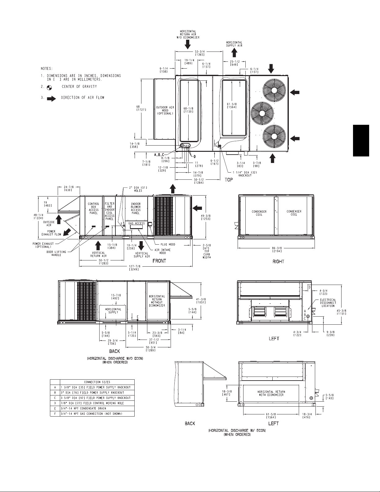
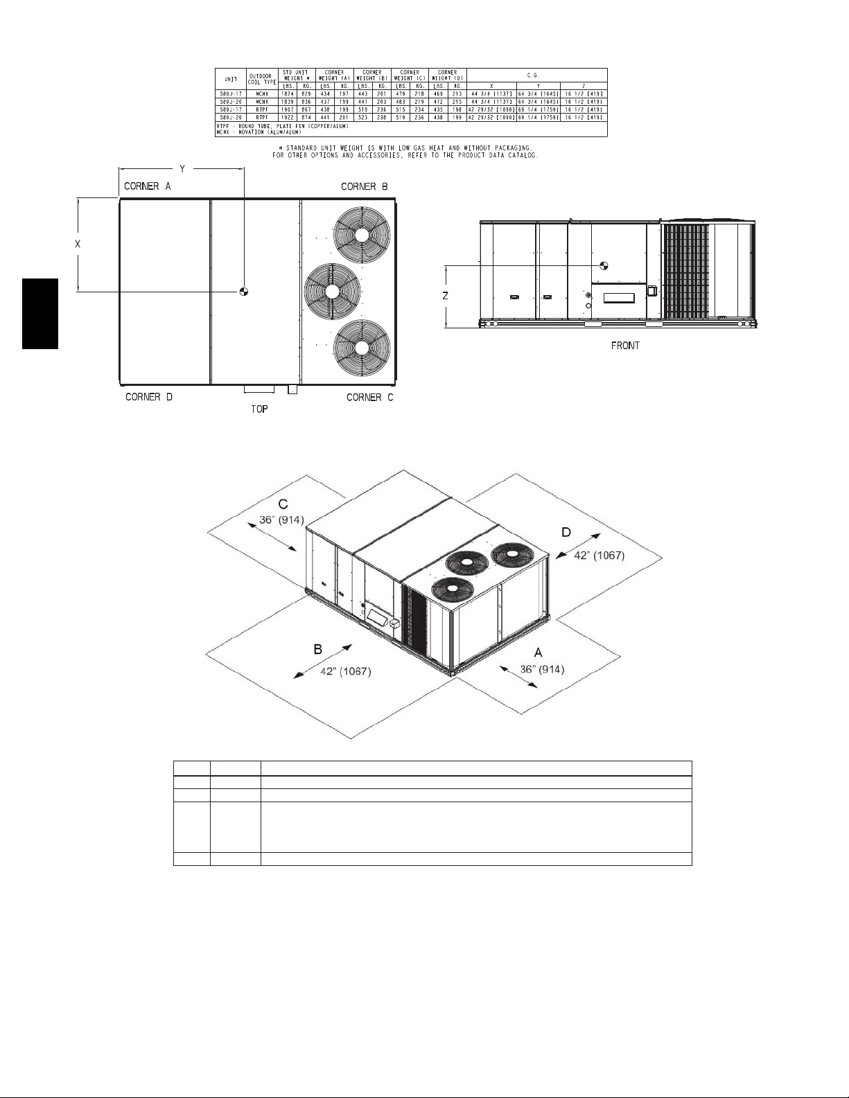
DIMENSIONS
580J
Fig. 1 -- Dimensions 580J*D17--20
15
C101009
Page 16
LOC
DIMENSION
CONDITION
A
36"
Recommended clearance for airflow and service.
B
42"
Recommended clearance for airflow and service.
C
18"
36"
42"
96"
D
42"
580J
DIMENSIONS (cont.)
C101038
Fig. 2 -- Dimensions 580J*D17--20
1. No CO, 2. No Economizer, 3. No field installed disconnect on economizer hood side (Factory installed disconnect installed).
1. CO installed, 2. Vertical surface behind servicer is electrically non-c onductive (e.g., wood, fiberglas s).
1. CO installed, 2. Vertical surface behind servicer is electrically conductive (e.g., metal, masonry)
1. Economizer and/or Power E xhaust installed. 2. Check for sources of flue products within 10 f eet of economizer fresh air intake.
Recommended clearance for s ervice
C11001
Fig. 3 -- Service Clearance
16
Page 17
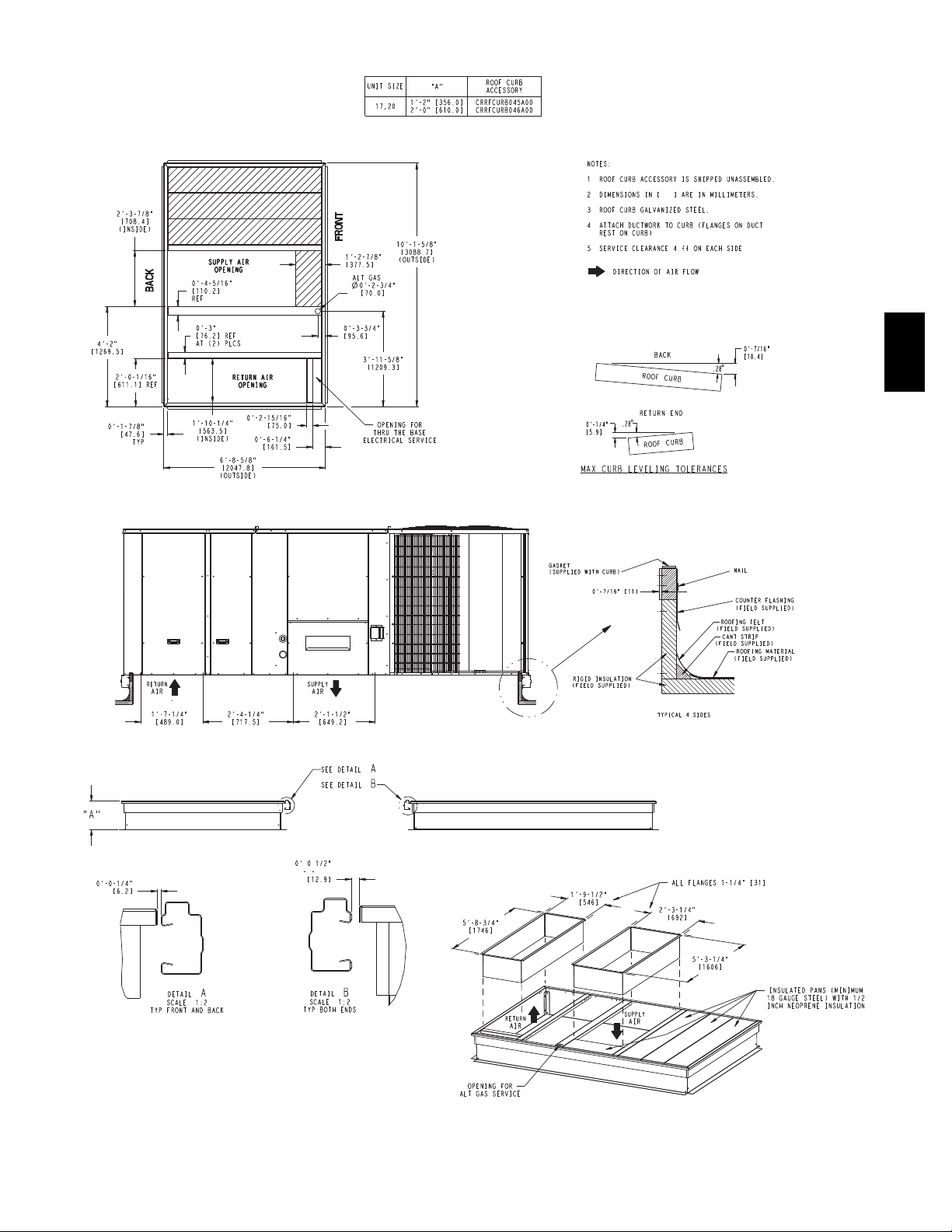
DIMENSIONS (cont.)
580J
Fig. 4 -- Curb Dimensions 580J*D17 --20
17
C09052
Page 18
580J
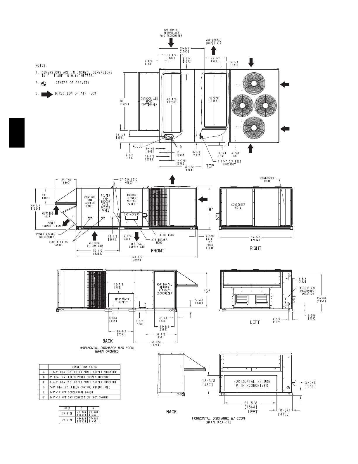
DIMENSIONS (cont.)
Fig. 5 -- Dimensions 580J*D24--28
18
C101039
Page 19

DIMENSIONS (cont.)
LOC
DIMENSION
CONDITION
A
36"
Recommended clearance for airflow and service.
B
42"
Recommended clearance for airflow and service.
C
18"
36"
42"
96"
D
42"
Fig. 6 -- 580JD24--28
580J
C101040B
1. No CO, 2. No Economizer, 3. No field installed disconnect on economizer hood side (Factory installed disconnect installed).
1. CO installed, 2. Vertical surface behind servicer is electrically non-c onductive (e.g., wood, fiberglas s).
1. CO installed, 2. Vertical surface behind servicer is electrically conductive (e.g., metal, masonry)
1. Economizer and/or Power E xhaust installed. 2. Check for sources of flue products within 10 f eet of economizer fresh air intake.
Recommended clearance for s ervice
C11001
Fig. 7 -- Service Clearance
19
Page 20

580J
DIMENSIONS (cont.)
Fig. 8 -- Curb Dimensions
20
C09100
Page 21

OPTIONS AND ACCESSORIES WEIGHT ADDERS
BASE UNIT WITH OPTIONS AND
ACCESSORIES
(Weight Adders)
Perfect Humidity
Base Unit Operating Weight 1907 865 1922 872 2072 940 2197 997
Power Exhaust 125 57 125 57 125 57 125 57
Economizer 170 77 170 77 170 77 195 88
Copper Tube/Fin Evaporator Coil 110 50 110 50 135 61 161 73
Low Gas Heat 85 39 85 39 85 39 85 39
Medium Gas Heat 90 41 90 41 90 41 90 41
High Gas Heat 113 51 113 51 113 51 113 51
Flue Discharge Deflector 7 3 7 3 7 3 7 3
Roof Curb 14 ---in (356mm) 240 109 240 109 240 109 240 109
Roof Curb 24 ---in (610mm) 340 154 340 154 340 154 340 154
Louvered Hail Guard 60 27 60 27 120 54 150 68
CO2sensor 5 2 5 2 5 2 5 2
Return Smoke Detector 5 2 5 2 5 2 5 2
Supply Smoke Detector 5 2 5 2 5 2 5 2
Fan/Filter Status Switch 2 1 2 1 2 1 2 1
Non --- Fused Disconnect 15 7 15 7 15 7 15 7
Powered Convenience Outlet 35 16 35 16 35 16 35 16
Non---Powered Convenience Outlet 5 2 5 2 5 2 5 2
Enthalpy Sensor 2 1 2 1 2 1 2 1
Differential Enthalpy Sensor 3 1 3 1 3 1 3 1
Two Position Motorized Damper 50 23 50 23 50 23 65 29
Manual Damper 35 16 35 16 35 16 40 18
Field Filter Track 4 ---in (102mm) 12 5 12 5 12 5 12 5
MotorMaster Controller 35 16 35 16 35 16 35 16
Standard Static Motor/Drive 0 0 0 0 0 0 0 0
Medium Static Motor/Drive 5 2 6 3 6 3 6 3
High Static Motor/Drive 11 5 12 5 16 7 16 7
Barometric Relief Hood (Horizontal) 25 11 25 11 25 11 25 11
1
For Perfect Humidity add MotorMaster Controller.
1
580J*17 580J*20 580J*24 580J*28
lb kg lb kg lb kg lb kg
83 38 83 38 83 38 92 42
MAX W EIGHT ADDER
580J
21
Page 22

APPLICATION/SELECTION DATA
Min operating ambient temp (cooling):
In mechanical cooling mode, your Bryant rooftop unit can
safely operate down to an outdoor ambient temperature of
30_F(--1_C). It is possible to provide cooling at lower
outdoor ambient temperatures by using less outside air,
economizers, and/or accessory low ambient kits.
Max operating ambient temp (cooling):
The maximum operating ambient temperature for cooling
mode is 115_F(46_C). While cooling operation above
115_F(46_C) may be possible, it could cause either a
reduction in performance, reliability, or a protective action
by the unit’s internal safety devices.
Min mixed air temp (heating):
580J
Using the factory settings, the minimum temperatures for
the mixed air (the combined temperature of the warm
return air and the cold outdoor air) entering the dimpled,
gas heat exchangers are:
Aluminized Stainless Steel
50_F(10_C) continuous
45_F(7_C) intermittent
Operating at lower mixed--air temperatures may be
possible, if a field--supplied, outdoor air thermostat
initiates both heat stages when the temperature is less than
the minimum temperatures listed above. Please contact
your local Bryant representative for assistance.
40_F(4_C) continuous
35_F(2_C) intermittent
Min and max airflow (heating and cooling):
To maint ain safe and reliable operation of your rooftop,
operate within the heating airflow limits during heating
mode and cooling airflow limits during cooling mode.
Operating above the max may cause blow--off, undesired
airflow noise, or airflow related problems with the rooftop
unit. Operating below the min may cause problems with
coil freeze--up and unsafe heating operation. Heating and
cooling limitations differ when evaluating operating CFM,
the minimum value is the HIGHER of the cooling and
heating minimum CFM values published in Table 5 and
the maximum value is the LOWER of the cooling and
heating minimum values published in Table 5.
Heating--to--cooling changeover:
Your unit will automatically change from heating to
cooling mode when using a thermostat with an
auto--change--over feature.
Airflow:
All units are draw--through in cooling mode and
blow--through in heating mode.
Outdoor air application strategies:
Economizers reduce operating expenses and compressor
run time by providing a free source of cooling and a
means of ventilation to match application changing needs.
In fact, they should be considered for most applications.
Also, consider the various economizer control methods
and their benefits, as well as sensors required to
accomplish your application goals. Please contact your
local Bryant representative for assistance.
Motor limits, break horsepower ( BHP) :
Due to internal design of Bryant units, the air path, and
specially designed motors, the f ull horsepower (maximum
continuous BHP) band, as listed in Physical Data Table
Cooling, can be used with the utmost confidence. There is
no need for extra safety factors, as Bryant motors are
designed and rigorously tested to use the entire, listed
BHP range without either nuisance tripping or premature
motor failure.
Propane heating:
Propane has different physical qualities than natural gas.
As a result, Propane requires different fuel to air mixture.
To optimize the fuel/air mixture for Propane, Bryant sells
different burner orifices in an easy to install accessory kit.
To select the correct burner orifices or determine the hea t
capacity for an Propane application, use either the
selection software, or the unit’s service manual.
High altitude heating:
High altitudes have less oxygen, which affects the fuel/air
mixture in heat exchangers. In order to maintain a proper
fuel/air mixture, heat exchangers operating in altitudes
above 2000 ft (610m) require different orifices. To select
the correct burner orifices or determine the heat capacity
for a high altitude application, use either the selection
software, or the unit’s service manual.
High altitudes have less oxygen, which means heat
exchangers need less fuel. The new gas orifices in this
field--installed kit make the necessary adjustment for high
altitude applications. They restore the optimal fuel to air
mixture and maintain healthy combustion on altitudes
above 2000 ft (610m).
NOTE: Typical natural gas heating value ranges from
975 to 1050 Btu/ft
value goes down approximately 1.7% per every thousand
feet elevation. Standard factory orifices can typically be
used up to 2000 ft (610m) elevation without any
operational issues.
NOTE: For installations in Canada, the input rating
should be derated by 10% for altitudes from 2000 ft
(610m) to 4500 ft (1372m) above sea level.
3
at sea level nationally. The heating
22
Page 23

APPLICATION/SELECTION DATA (cont.)
Sizing a rooftop
Bigger isn’t necessarily better. While an air conditioner
needs to have enough capacity to meet the design loads, it
doesn’t need excess capacity. In fact, excess capacity
typically results in very poor part load performance and
humidity control.
Using higher design temperatures than ASHRAE
recommends for your location, adding “safe ty factors” to
the calculated load, are all signs of oversizing air
conditioners. Oversizing the air conditioner leads to poor
humidity control, reduced efficiency, higher utility bills,
larger indoor temperature swings, excessive noise, and
increased wear and tear on the air conditioner.
Rather than oversizing an ai r conditioner, engineers
should “right--size” or even slightly undersize air
conditioners. Correctly sizing an air conditioner controls
humidity better; promotes efficiency; reduces utility bills;
extends equipment life, and maintains even, comfortable
temperatures. Please contact your local Bryant
representative for assistance.
Low ambient applications
The optional Bryant economizer can adequately cool your
space by bringing in fresh, cool outside air. In fact, when
so equipped, accessory low--ambient kit may not be
necessary. In low ambient conditions, unless the outdoor
air is excessively humid or contaminated,
economizer--based “free cooling” is the preferred less
costly and energy conscious method.
In low ambient applications where outside air might not
be desired (such as contaminated or excessively humid
outdoor environments), your Bryant rooftop can operate to
ambient temperatures down to -- 20_F(--29_C) using the
recommended accessory Motormaster low ambient
controller or down to 25_F(--4_C) with the field installed
Winter Start Package.
Application/Selection Option
Selection software by Bryant saves time by performing
many of the steps above. Contact your Bryant sales
representative for assistance.
580J
23
Page 24

Table 9 – COOLING CAPACITIES 2--Stage Cooling 15 TONS
AMBIENT TEMPERATURE
580J*17D
75 80 85 75 80 85 75 80 85 75 80 85
TC 159.6 159.1 163.4 148.7 148.4 155.2 136.1 137.1 146.0 122.4 127.2 136.2
58
SHC 132.6 149.6 163.4 127.0 143.9 155.2 120.7 137.1 146.0 113.9 127.2 136.2
TC 173.9 173.6 173.3 163.1 162.6 162.2 150.5 150.2 149.9 136.8 136.2 136.9
62
SHC 119.4 136.8 153.9 114.1 131.5 148.6 108.2 125.7 142.6 101.9 119.2 135.8
TC 193.4 193.0 192.5 182.5 182.1 181.7 169.9 169.5 169.1 156.0 155.5 155.2
67
SHC 102.3 119.7 137.0 97.3 114.8 132.3 91.7 109.4 126.9 85.7 103.5 121.1
580J
4500 CFM
5250 CFM
6000 CFM
6750 CFM
7500 CFM
EAT (wb)
EAT (wb)
EAT (wb)
EAT (wb)
EAT (wb)
TC 213.7 213.2 212.6 203.5 203.0 202.5 191.0 190.5 189.9 177.1 176.6 176.1
72
SHC 84.0 101.7 119.2 79.7 97.4 115.0 74.6 92.4 109.9 69.1 86.9 104.6
TC --- 227.8 228.5 --- 219.6 219.1 --- 207.9 207.4 --- 194.1 193.5
76
SHC --- 89.9 103.7 --- 82.5 100.2 --- 78.1 95.8 --- 73.0 97.2
TC 168.7 168.5 176.4 157.0 158.2 167.7 143.9 148.2 158.0 129.5 137.5 147.4
58
SHC 161.3 163.9 176.4 138.9 157.2 167.7 132.4 148.2 158.0 125.4 137.5 147.4
TC 184.2 183.8 183.2 172.3 171.8 171.5 159.1 158.5 159.3 144.4 143.8 147.8
62
SHC 129.4 149.6 168.9 123.9 144.0 163.5 117.9 137.9 156.4 111.4 131.3 147.8
TC 204.7 204.0 203.5 193.1 192.6 192.2 179.7 179.2 178.7 164.8 164.3 163.6
67
SHC 109.3 129.5 149.6 104.3 124.7 144.9 98.6 119.1 139.4 92.5 113.1 133.3
TC 224.6 224.1 223.6 214.4 213.7 213.1 202.0 201.4 200.7 187.0 186.4 185.8
72
SHC 87.5 107.9 128.2 83.4 103.9 124.3 78.6 99.2 119.6 72.9 93.6 114.1
TC --- 239.1 239.6 --- 230.6 230.1 --- 218.4 217.7 --- 204.4 203.7
76
SHC --- 92.6 110.2 --- 86.4 107.0 --- 82.0 102.6 --- 77.1 97.8
TC 176.9 178.5 188.9 164.3 168.9 179.6 150.3 158.4 169.1 136.1 146.9 157.7
58
SHC 157.4 178.5 188.9 151.1 168.9 179.6 144.3 158.4 169.1 136.1 146.9 157.7
TC 193.2 192.7 192.2 180.4 179.7 180.7 166.2 165.6 170.1 150.5 150.0 158.1
62
SHC 140.2 162.8 184.2 134.4 156.9 177.8 128.1 150.6 168.9 121.3 143.5 158.1
TC 214.4 213.7 213.0 202.1 201.6 201.0 187.7 187.1 186.4 171.8 171.1 170.4
67
SHC 117.3 140.3 163.0 112.1 135.3 158.2 106.2 129.4 152.2 99.8 123.1 145.9
TC 234.9 234.6 234.2 224.0 223.3 222.5 210.9 210.1 209.3 194.9 194.1 193.4
72
SHC 92.7 115.9 139.1 88.4 111.8 134.8 83.4 106.8 130.0 77.5 101.0 124.3
TC --- 250.7 250.9 --- 240.9 240.1 --- 227.5 226.7 --- 212.7 211.8
76
SHC --- 95.7 118.9 --- 92.1 115.3 --- 87.4 110.8 --- 82.4 105.8
TC 182.5 187.4 198.5 169.3 177.4 188.7 156.0 166.4 177.8 142.9 154.4 165.9
58
SHC 167.5 187.4 198.5 161.2 177.4 188.7 153.0 166.4 177.8 142.9 154.4 165.9
TC 199.3 198.7 199.6 186.0 185.2 188.9 171.2 170.5 208.4 154.7 155.5 166.2
62
SHC 148.6 173.7 196.6 142.8 167.6 188.9 136.4 161.1 208.4 115.2 152.6 166.2
TC 220.4 219.6 218.8 208.2 207.4 206.6 193.2 192.5 191.7 176.8 176.1 175.2
67
SHC 122.6 148.2 173.6 117.6 143.4 168.7 111.6 137.6 162.9 97.2 131.3 156.3
TC 241.2 240.5 240.2 229.8 228.9 228.1 216.3 215.4 214.6 200.2 199.4 198.6
72
SHC 95.1 120.9 146.6 90.8 116.8 142.6 85.8 111.9 137.8 80.0 106.2 118.0
TC --- 257.2 256.7 --- 246.6 245.9 --- 233.0 232.1 --- 217.6 216.7
76
SHC --- 98.4 124.2 --- 94.8 120.7 --- 90.2 116.3 --- 85.1 111.3
TC 187.3 195.3 206.8 174.4 184.9 196.8 161.5 173.5 185.5 148.9 161.1 173.2
58
SHC 177.5 195.3 206.8 169.9 184.9 196.8 161.5 173.5 185.5 148.9 161.1 173.2
TC 204.3 203.5 207.1 190.6 189.9 197.1 175.1 175.4 185.7 158.4 161.2 173.5
62
SHC 156.5 183.9 207.1 150.7 177.9 197.1 144.1 170.2 185.7 137.1 161.2 173.5
TC 225.2 224.4 223.4 213.1 212.2 211.3 197.8 197.0 196.2 180.8 179.9 179.1
67
SHC 127.5 155.8 183.5 122.8 151.2 178.9 116.8 145.5 173.1 110.3 139.0 166.3
TC 246.1 245.5 244.9 234.5 233.6 232.8 220.6 219.7 218.6 204.7 203.7 202.7
72
SHC 97.1 125.6 153.8 92.9 121.6 150.1 87.9 116.8 145.3 82.3 111.2 139.9
TC --- 262.3 261.6 --- 251.3 250.5 --- 237.3 236.3 --- 221.6 220.6
76
SHC --- 100.9 129.2 --- 97.3 125.8 --- 92.8 121.5 --- 87.7 116.6
LEGEND:
--- --- D o n o t o p er a t e
Cfm --- Cubic feet per minute (supply air)
EAT(db) --- Entering air temperature (dry bulb)
EAT(wb) --- Entering air temperature (wet bulb)
SHC --- Sensible heat capacity
TC --- Total capacity
85 95 105 115
EAT (db) EAT (db) EAT (db) EAT (db)
24
Page 25

Table 10 – COOLING CAPACITIES 2--Stage Cooling 15 TONS (con’t)
580J017 (15 TONS) --- UNIT WITH PERFECT HUMIDITY IN SUBCOOLING MODE
AIR ENTERING EVAPORATOR --- CFM/BF
Tem p (F) A ir E n t
Condenser (Edb)
72 67 62 72 67 62 72 67 62
TC 208.5 190.6 172.6 229.2 208.6 188.1 247.8 224.9 202.0
75
SHC 94.0 114.5 135.0 104.5 125.2 145.9 113.0 133.8 154.6
kW 13.42 13.05 12.70 13.60 13.21 12.80 13.82 13.36 13.15
TC 198.3 180.7 163.0 214.9 194.8 174.6 229.8 207.4 185.1
85
SHC 74.1 99.6 125.1 85.2 110.9 136.7 94.1 120.0 145.9
kW 14.79 14.42 14.10 14.97 14.58 14.20 15.19 14.73 14.51
TC 188.2 170.8 153.4 200.6 180.9 161.1 211.9 190.0 168.1
95
SHC 54.4 84.8 115.3 65.9 96.7 127.5 75.1 106.2 137.2
kW 16.23 15.86 15.50 16.41 16.02 15.60 16.63 16.17 15.95
TC 178.1 160.9 143.8 186.4 167.0 147.7 193.9 172.5 151.2
105
SHC 34.6 70.0 105.4 46.5 82.4 118.2 56.1 92.3 128.5
kW 17.47 17.10 16.80 17.65 17.26 16.90 17.87 17.41 17.25
TC 167.9 151.1 134.2 172.1 153.2 134.2 175.9 155.1 134.5
115
SHC 14.8 55.2 95.6 27.2 68.1 109.0 37.1 78.5 119.8
kW 18.87 18.50 18.20 19.05 18.66 18.30 19.27 18.81 18.55
580J017 (15 TONS) --- UNIT WITH PERFECT HUMIDITY IN HOT GAS REH EAT MODE
Tem p (F) A ir E n t
Condenser (Edb)
4,500 6,000 7,500 4,500 6,000 7,500 4,500 6,000 7,500
TC 80.10 85.50 91.30 82.70 90.90 97.10 86.00 95.40 100.50
80
SHC 12.70 22.30 34.20 5.10 12.10 21.20 ---2.10 4.20 10.50
kW 12.44 12.67 12.78 12.55 12.88 13.10 12.65 13.02 13.12
TC 82.30 87.60 93.40 84.70 93.00 99.20 88.10 97.30 102.50
75
SHC 14.30 24.20 36.00 6.70 13.70 23.10 ---0.50 5.80 12.60
kW 12.38 12.62 12.73 12.50 12.83 13.05 12.62 12.98 13.07
TC 84.40 89.60 94.70 87.00 95.10 101.30 90.30 99.50 104.60
70
SHC 16.10 25.70 37.30 8.20 15.80 24.50 1.10 7.50 13.70
kW 12.34 12.58 12.69 12.47 12.78 13.03 12.59 12.93 13.02
TC 88.50 93.90 99.80 91.20 99.40 105.50 94.40 103.70 108.90
60
SHC 19.40 29.20 40.70 11.50 18.60 27.80 4.60 10.50 16.90
kW 12.28 12.52 12.63 12.41 12.73 12.97 12.53 12.84 12.94
TC 92.80 98.10 104.80 95.40 103.60 110.50 98.80 108.00 113.90
50
SHC 22.70 32.20 43.80 14.80 22.10 31.30 7.70 13.90 20.50
kW 12.21 12.45 12.56 12.34 12.68 12.91 12.46 12.75 12.85
TC 97.10 102.50 108.50 99.60 108.00 114.30 103.00 112.40 117.70
40
SHC 26.00 35.40 46.90 17.90 25.30 34.40 10.80 17.10 23.80
kW 12.14 12.38 12.49 12.27 12.60 12.84 12.40 12.70 12.80
LEGEND
Edb --- E n t e r i n g D r y --- B u l b
Ewb --- E n t e r i n g W e t --- B u l b
kW --- Compressor Motor Power Input
Idb --- L e a v i n g D r y --- B u l b
Iwb --- L e a v i n g W e t --- B u l b
SHC --- Sensible Heat Capacity (1000 Btuh) Gross
TC --- Total Capacity (1000 Btuh) Gross
4,500 6,000 7,500
A i r E n t e r i n g E v a p o r a t o r --- --- E w b ( F )
AIR ENTERING EVAPORATOR --- Ewb (F)
75 Dry Bulb 75 Dry Bulb 75 Dry Bulb
62.5 Wet Bulb 64 Wet Bulb 65.3 Wet Bulb
(50% Relative) (56% Relative) (60% Relative)
A i r E n t e r i n g E v a p o r a t o r --- C f m
NOTES:
1. Direct interpolation is permissible. Do not extrapolate.
2. The following formulas may be used:
t
ldb=tedb
t
= Wet ---bulb temperature corresponding to enthalpy of air
lwb
leaving evaporator coil (h
h
lwb=hewb
Where: h
sensible capacity (Btuh)
–
–
= Enthalpy of air entering evaporator coil
ewb
1.10 x cfm
)
lwb
total capacity (Btuh)
4.5 x cfm
580J
25
Page 26

Table 11 – COOLING CAPACITIES 2--Stage Cooling 17.5 TONS
AMBIENT TEMPERATURE
580J*20D
75 80 85 75 80 85 75 80 85 75 80 85
TC 180.4 185.6 196.3 167.7 176.1 186.9 154.7 165.3 176.6 142.2 153.6 164.9
58
SHC 166.5 185.6 196.3 160.6 176.1 186.9 152.7 165.3 176.6 142.2 153.6 164.9
TC 196.2 195.5 196.9 183.6 182.9 187.2 169.3 168.7 176.9 153.4 154.1 165.2
62
SHC 146.8 172.1 194.7 141.4 166.6 187.2 135.4 160.5 176.9 128.6 152.5 165.2
TC 216.7 215.9 215.2 204.9 204.1 203.1 190.6 189.7 189.0 174.8 174.0 173.3
67
SHC 120.0 146.1 171.8 115.4 141.5 167.1 109.8 136.1 161.7 103.8 130.2 155.6
580J
5250 CFM
6125 CFM
7000 CFM
7875 CFM
8750 CFM
EAT (wb)
EAT (wb)
EAT (wb)
EAT (wb)
EAT (wb)
TC 237.4 236.8 236.0 226.0 225.1 224.2 212.8 211.9 211.0 197.3 196.4 195.5
72
SHC 92.0 118.3 144.3 87.8 114.3 140.4 83.0 109.6 135.8 77.6 104.2 130.6
TC --- 252.9 253.0 --- 242.5 241.6 --- 229.1 228.2 --- 214.1 213.1
76
SHC --- 95.1 121.4 --- 91.7 118.0 --- 87.3 113.8 --- 82.5 107.1
TC 188.8 198.5 209.3 176.5 188.2 200.2 164.5 176.7 189.0 151.9 164.2 176.7
58
SHC 180.4 198.5 209.3 174.4 188.2 200.2 164.5 176.7 189.0 151.9 164.2 176.7
TC 205.2 204.6 209.6 191.8 191.5 200.4 176.6 177.6 189.2 159.9 164.2 176.9
62
SHC 159.9 188.7 209.6 154.2 183.0 200.4 147.9 174.8 189.2 141.0 164.2 176.9
TC 225.5 224.5 223.5 213.5 212.5 211.7 199.1 198.3 197.4 182.3 181.4 180.9
67
SHC 128.3 158.4 187.8 123.8 154.1 183.5 118.4 148.9 178.1 112.2 142.7 171.6
TC 245.6 245.3 244.6 234.7 233.6 232.6 220.9 219.9 218.8 205.5 204.4 203.4
72
SHC 95.4 125.9 155.7 91.7 122.2 152.4 86.9 117.7 148.1 81.7 112.5 143.1
TC --- 262.0 261.2 --- 250.7 250.1 --- 237.3 236.2 --- 221.6 220.6
76
SHC --- 99.5 129.4 --- 95.9 126.2 --- 91.8 122.4 --- 87.0 117.8
TC 197.4 209.8 221.3 186.1 199.1 211.7 173.8 186.9 200.1 160.3 173.5 186.9
58
SHC 196.8 209.8 221.3 186.1 199.1 211.7 173.8 186.9 200.1 160.3 173.5 186.9
TC 212.7 212.4 221.5 198.4 199.8 212.0 182.3 186.9 200.3 164.7 173.8 187.1
62
SHC 173.4 205.1 221.5 167.4 197.4 212.0 160.8 186.8 200.3 153.4 173.8 187.1
TC 233.7 232.5 231.4 220.8 219.8 218.9 205.6 204.5 204.1 187.8 186.8 188.0
67
SHC 138.0 172.0 205.0 133.4 167.6 200.4 127.8 162.0 194.4 121.3 155.6 185.6
TC 254.3 253.3 252.8 242.7 241.5 240.3 228.0 226.8 225.7 211.8 210.6 209.3
72
SHC 101.3 135.4 169.2 97.3 131.8 165.9 92.3 127.2 161.5 86.9 121.8 156.3
TC --- 270.7 269.9 --- 259.0 258.1 --- 245.0 243.6 --- 228.5 227.1
76
SHC --- 106.1 140.0 --- 102.4 136.5 --- 98.2 132.7 --- 93.2 127.9
TC 205.0 217.2 229.1 193.4 206.9 219.3 180.6 194.3 207.9 166.6 180.5 194.5
58
SHC 205.0 217.2 229.1 193.4 206.9 219.3 180.6 194.3 207.9 166.6 180.5 194.5
TC 216.7 217.4 229.4 202.5 207.1 219.6 185.9 194.5 208.4 168.4 180.7 194.7
62
SHC 183.9 217.4 229.4 178.2 207.1 219.6 171.5 194.5 208.4 141.2 180.7 194.7
TC 237.8 236.7 235.7 224.7 223.5 223.0 209.5 208.3 209.2 191.5 190.3 195.0
67
SHC 144.6 182.4 219.3 140.3 178.2 213.7 134.9 172.7 205.9 113.6 166.2 195.0
TC 258.6 257.5 256.5 246.8 245.7 244.3 231.8 230.5 229.2 215.3 213.9 212.5
72
SHC 103.9 141.8 179.2 100.0 138.3 176.1 95.1 133.9 172.1 89.7 128.6 142.0
TC --- 275.4 274.2 --- 262.7 261.8 --- 248.7 247.6 --- 231.9 230.5
76
SHC --- 109.5 147.0 --- 105.7 143.6 --- 101.5 139.9 --- 96.6 135.4
TC 211.3 223.6 235.9 199.7 213.4 225.7 186.4 200.7 214.3 172.1 186.5 200.9
58
SHC 211.3 223.6 235.9 199.7 213.4 225.7 186.4 200.7 214.3 172.1 186.5 200.9
TC 220.0 223.7 236.3 206.0 213.6 226.1 189.3 200.9 214.5 172.2 186.7 201.2
62
SHC 194.0 223.7 236.3 188.5 213.6 226.1 181.3 200.9 214.5 172.2 186.7 201.2
TC 241.1 240.1 239.7 227.9 226.6 226.9 212.7 211.4 214.9 194.4 193.0 201.4
67
SHC 151.0 192.1 230.2 146.9 188.3 225.2 141.6 182.9 214.8 135.3 176.3 201.4
TC 262.2 261.0 259.7 250.0 248.8 247.7 235.0 233.5 232.1 218.1 216.6 215.2
72
SHC 106.5 148.1 189.0 102.5 144.5 186.0 97.8 140.4 182.1 92.4 135.3 177.1
TC --- 278.9 277.4 --- 266.0 264.8 --- 251.5 250.6 --- 234.7 233.0
76
SHC --- 112.7 153.7 --- 108.9 150.4 --- 104.7 146.7 --- 100.0 142.4
LEGEND:
--- --- D o n o t o p er a t e
Cfm --- Cubic feet per minute (supply air)
EAT(db) --- Entering air temperature (dry bulb)
EAT(wb) --- Entering air temperature (wet bulb)
SHC --- Sensible heat capacity
TC --- Total capacity
85 95 105 115
EAT (db) EAT (db) EAT (db) EAT (db)
26
Page 27

Table 12 – COOLING CAPACITIES 2--Stage Cooling 17.5 TONS (con’t)
580J020 (17.5 TONS) --- UNIT WITH PERFECT HUMIDITY IN SUBCOOLING MODE
AIR ENTERING EVAPORATOR --- CFM/BF
Tem p (F) A ir E n t
Condenser (Edb)
72 67 62 72 67 62 72 67 62
TC 218.7 199.6 180.5 241.4 219.4 197.4 261.7 237.2 212.7
75
SHC 99.9 123.9 147.8 112.7 136.9 161.1 122.9 147.3 171.7
kW 11.81 11.56 11.20 13.81 13.48 13.16 14.82 14.58 14.16
TC 206.6 187.9 169.1 224.9 203.4 181.9 241.3 217.3 193.4
85
SHC 78.9 108.4 137.9 92.2 122.1 152.0 103.0 133.1 163.3
kW 13.18 12.53 12.53 15.18 14.85 14.52 16.21 15.85 15.54
TC 194.7 176.2 157.8 208.4 187.4 166.4 220.8 197.4 174.1
95
SHC 57.8 92.9 128.0 71.7 107.3 142.9 83.0 118.9 154.9
kW 14.56 14.21 13.88 16.56 16.21 15.87 17.56 17.22 16.01
TC 182.7 164.5 146.4 191.9 171.4 150.8 200.3 177.6 154.8
105
SHC 36.8 77.4 118.1 51.3 92.5 133.8 63.0 104.7 146.4
kW 15.93 15.58 15.20 17.94 17.58 17.22 18.95 18.59 18.24
TC 170.6 152.8 135.0 175.4 155.4 135.3 179.8 157.7 135.5
115
SHC 15.7 62.0 108.2 30.8 77.8 124.7 43.0 90.5 128.0
kW 17.31 16.95 16.58 19.32 18.95 18.58 20.32 19.96 19.59
580J020 (17.5 TONS) --- UNIT WITH PERFECT HUMIDITY IN HOT GAS REHEAT MODE
Tem p (F) A ir E n t
Condenser (Edb)
5,250 7,000 8,750 5,250 7,000 8,750 5,250 7,000 8,750
TC 82.20 90.50 92.40 86.70 96.40 97.80 91.60 99.80 101.20
80
SHC 18.20 29.40 41.60 8.60 17.20 27.50 0.50 9.30 13.20
kW 12.64 12.73 12.88 12.78 13.06 13.15 12.96 13.07 13.22
TC 84.40 92.70 94.40 88.80 98.60 99.70 93.70 102.00 103.40
75
SHC 19.70 31.30 43.50 10.10 18.80 29.20 12.10 10.80 15.30
kW 12.60 12.71 12.85 12.75 13.02 13.12 12.93 13.03 13.19
TC 86.70 94.90 96.60 91.00 100.70 102.00 95.90 104.10 105.40
70
SHC 21.30 32.80 44.80 11.60 20.40 30.70 3.80 12.30 16.50
kW 12.56 12.66 12.82 12.70 12.99 13.08 12.89 13.00 13.14
TC 90.90 99.10 100.80 95.20 105.00 106.30 100.20 108.30 109.70
60
SHC 24.80 36.00 48.20 14.90 23.90 35.90 7.20 15.60 19.60
kW 12.49 12.60 12.75 12.64 12.92 13.02 12.83 12.93 13.09
TC 95.00 103.40 105.10 99.50 109.40 110.50 104.40 112.50 113.90
50
SHC 28.10 39.30 51.30 18.20 27.20 37.40 10.30 18.90 23.20
kW 12.43 12.53 12.67 12.57 12.86 12.95 12.76 12.87 13.02
TC 99.20 107.70 109.30 103.70 113.70 114.70 108.60 116.70 118.10
40
SHC 31.40 42.50 54.40 21.30 30.40 40.50 13.40 22.00 26.50
kW 12.35 12.45 12.61 12.50 12.79 12.87 12.68 12.80 12.94
LEGEND
Edb --- E n t e r i n g D r y --- B u l b
Ewb --- E n t e r i n g W e t --- B u l b
kW --- Compressor Motor Power Input
Idb --- L e a v i n g D r y --- B u l b
Iwb --- L e a v i n g W e t --- B u l b
SHC --- Sensible Heat Capacity (1000 Btuh) Gross
TC --- Total Capacity (1000 Btuh) Gross
5,250 7,000 8,750
A i r E n t e r i n g E v a p o r a t o r --- --- E w b ( F )
AIR ENTERING EVAPORATOR --- Ewb (F)
75 Dry Bulb 75 Dry Bulb 75 Dry Bulb
62.5 Wet Bulb 64 Wet Bulb 65.3 Wet Bulb
(50% Relative) (56% Relative) (60% Relative)
A i r E n t e r i n g E v a p o r a t o r --- C f m
NOTES:
1. Direct interpolation is permissible. Do not extrapolate.
2. The following formulas may be used:
t
ldb=tedb
t
= Wet ---bulb temperature corresponding to enthalpy of air
lwb
leaving evaporator coil (h
h
lwb=hewb
Where: h
sensible capacity (Btuh)
–
–
= Enthalpy of air entering evaporator coil
ewb
1.10 x cfm
)
lwb
total capacity (Btuh)
4.5 x cfm
580J
27
Page 28

Table 13 – COOLING CAPACITIES 2--Stage Cooling 20 TONS
AMBIENT TEMPERATURE
580J*24D
75 80 85 75 80 85 75 80 85 75 80 85
TC 213.1 217.2 228.7 199.9 207.5 219.4 184.8 195.8 208.4 169.6 182.6 195.6
58
SHC 194.3 217.2 228.7 188.0 207.5 219.4 179.0 195.8 208.4 169.6 182.6 195.6
TC 230.0 229.4 230.4 217.5 217.0 219.7 202.5 201.9 208.8 184.9 184.9 195.9
62
SHC 170.0 199.9 225.9 164.6 194.5 219.7 158.3 187.8 208.8 150.9 178.7 195.9
TC 251.5 251.1 250.6 239.4 238.7 238.1 225.4 224.7 224.0 208.8 208.2 207.4
67
SHC 137.5 168.1 198.4 132.9 163.4 193.7 127.5 158.1 188.2 121.1 151.9 181.9
580J
6000 CFM
7000 CFM
8000 CFM
9000 CFM
10,000 CFM
EAT (wb)
EAT (wb)
EAT (wb)
EAT (wb)
EAT (wb)
TC 274.0 273.8 273.5 262.3 261.7 261.0 248.2 247.4 246.6 232.2 231.3 230.5
72
SHC 104.3 135.1 165.6 100.1 130.9 161.4 95.1 125.9 156.6 89.6 120.5 151.3
TC --- 292.9 292.2 --- 280.5 279.9 --- 266.3 265.6 --- 250.6 249.8
76
SHC --- 108.1 138.6 --- 104.1 134.9 --- 99.6 130.4 --- 94.6 125.5
TC 220.8 229.7 241.7 208.4 219.7 232.2 194.3 208.1 221.0 180.1 194.2 207.9
58
SHC 211.0 229.7 241.7 203.1 219.7 232.2 194.3 208.1 221.0 180.1 194.2 207.9
TC 237.8 237.3 241.9 225.1 224.6 232.3 209.6 210.2 221.3 191.3 196.0 208.2
62
SHC 183.3 217.8 241.9 178.2 212.1 232.3 171.8 203.8 221.3 164.3 196.0 208.2
TC 260.0 259.2 258.5 247.2 246.4 245.7 232.7 231.9 231.7 215.8 215.0 214.3
67
SHC 146.0 181.0 215.7 141.3 176.5 211.2 136.0 171.3 206.3 129.8 165.3 199.4
TC 283.3 282.5 281.8 270.6 269.8 268.9 255.9 255.0 254.1 240.0 238.9 238.0
72
SHC 107.9 143.2 178.1 103.6 139.0 174.1 98.6 134.2 169.5 93.2 129.0 164.4
TC --- 302.3 301.6 --- 289.1 288.4 --- 274.4 273.6 --- 257.9 256.8
76
SHC --- 112.3 147.5 --- 108.3 143.7 --- 103.9 139.4 --- 98.9 134.5
TC 232.1 243.6 256.1 219.8 233.4 246.0 206.9 221.3 234.5 192.1 206.8 221.2
58
SHC 227.5 243.6 256.1 219.8 233.4 246.0 206.9 221.3 234.5 192.1 206.8 221.2
TC 247.8 247.1 256.4 234.7 235.5 246.2 218.7 221.1 234.7 199.5 207.0 221.4
62
SHC 199.5 236.7 256.4 194.3 229.1 246.2 187.8 221.1 234.7 179.9 207.0 221.4
TC 270.2 269.3 268.3 257.0 256.1 255.2 242.1 241.0 240.3 224.5 223.5 223.1
67
SHC 157.6 197.1 235.6 152.7 192.6 231.0 147.3 187.2 225.3 141.0 181.0 215.6
TC 294.1 293.1 292.2 280.7 279.7 278.4 265.9 264.7 263.8 248.9 247.6 246.6
72
SHC 114.8 154.6 193.9 110.3 150.4 190.0 105.4 145.6 185.5 99.7 140.1 180.2
TC --- 313.1 312.3 --- 299.3 298.2 --- 283.8 282.8 --- 266.7 265.4
76
SHC --- 120.2 159.6 --- 116.0 155.9 --- 111.4 151.5 --- 106.2 146.6
TC 238.5 252.5 266.0 226.8 241.6 255.6 213.1 228.2 243.0 197.5 213.0 229.2
58
SHC 238.5 252.5 266.0 226.8 241.6 255.6 213.1 228.2 243.0 197.5 213.0 229.2
TC 253.0 254.1 266.3 238.6 241.6 255.7 221.0 228.4 243.3 201.1 213.2 229.4
62
SHC 211.9 249.1 266.3 206.2 241.6 255.7 199.2 228.4 243.3 164.2 213.2 229.4
TC 276.9 275.8 274.8 263.0 261.8 261.0 246.5 245.2 246.6 228.2 225.9 229.6
67
SHC 165.6 209.9 252.2 160.7 205.1 247.0 154.9 199.3 238.5 132.3 192.7 229.6
TC 302.2 301.0 299.7 287.9 286.6 285.4 272.3 270.9 269.6 254.3 252.9 251.6
72
SHC 118.2 162.8 206.8 113.5 158.4 202.9 108.5 153.4 198.0 102.7 147.8 165.1
TC --- 322.0 320.8 --- 307.7 306.1 --- 291.4 289.9 --- 275.1 272.5
76
SHC --- 124.5 168.7 --- 120.4 164.9 --- 115.6 160.5 --- 110.9 155.3
TC 245.7 259.8 273.9 233.8 248.7 263.2 219.8 235.3 250.5 203.7 219.8 236.5
58
SHC 245.7 259.8 273.9 233.8 248.7 263.2 219.8 235.3 250.5 203.7 219.8 236.5
TC 256.8 260.7 274.2 242.2 249.0 263.3 224.6 235.6 250.6 205.6 220.0 236.8
62
SHC 223.8 258.4 274.2 218.1 249.0 263.3 211.0 235.6 250.6 199.3 220.0 236.8
TC 280.8 279.6 266.3 266.6 265.4 265.8 249.9 248.6 251.0 231.4 229.8 237.3
67
SHC 173.2 221.8 266.3 168.3 217.0 258.7 162.6 211.4 250.7 156.4 204.7 237.3
TC 306.4 305.0 274.8 292.1 290.6 289.3 276.0 274.3 273.0 257.5 256.0 254.6
72
SHC 121.2 170.1 252.2 116.6 165.9 214.8 111.5 161.0 210.0 105.7 155.4 204.5
TC --- 326.2 299.7 --- 311.4 310.0 --- 295.2 293.2 --- 277.0 275.3
76
SHC --- 128.2 206.8 --- 124.0 172.9 --- 119.5 168.9 --- 114.3 163.8
LEGEND:
--- --- D o n o t o p er a t e
Cfm --- Cubic feet per minute (supply air)
EAT(db) --- Entering air temperature (dry bulb)
EAT(wb) --- Entering air temperature (wet bulb)
SHC --- Sensible heat capacity
TC --- Total capacity
85 95 105 115
EA (db) EA (db) EA (db) EA (db)
28
Page 29

Table 14 – COOLING CAPACITIES 2--Stage Cooling 20 TONS (con’t)
580J024 (20 TONS) --- UNIT WITH PERFECT HUMIDITY IN SUBCOOLING MODE
AIR ENTERING EVAPORATOR --- CFM/BF
Tem p (F) A ir E n t
Condenser (Edb)
72 67 62 72 67 62 72 67 62
TC 263.0 240.4 217.7 301.0 274.0 246.9 336.9 305.6 274.4
75
SHC 125.3 151.6 178.0 144.4 171.1 198.0 160.0 186.9 213.9
kW 15.63 15.20 14.65 15.91 15.62 14.98 16.26 15.92 15.21
TC 248.2 226.1 204.0 279.2 252.9 226.6 308.4 278.2 248.0
85
SHC 98.9 131.7 164.5 118.6 152.0 185.3 134.6 168.4 202.2
kW 17.50 17.04 16.50 17.74 17.51 16.75 18.08 17.73 17.03
TC 233.4 211.8 190.2 257.3 231.8 206.4 279.8 250.7 221.5
95
SHC 72.4 111.8 151.1 92.7 132.8 172.9 109.3 149.9 190.6
kW 19.36 18.96 18.35 19.61 19.37 18.67 20.02 19.62 18.97
TC 218.6 197.5 176.5 235.4 210.7 186.1 251.3 223.2 195.1
105
SHC 46.0 91.8 137.7 66.9 113.6 160.4 83.9 131.4 178.9
kW 21.23 20.76 20.18 21.53 21.22 20.52 21.91 21.52 20.77
TC 203.7 183.3 162.8 213.5 189.7 165.8 222.7 195.7 168.7
115
SHC 19.5 71.9 124.2 41.0 94.4 147.9 58.5 112.9 157.2
kW 23.02 22.58 22.02 23.42 23.02 22.38 23.73 23.41 22.57
580J024 (20 T ONS) --- UNIT WITH Perfect Humidity IN HOT GAS REHEAT MODE
Tem p (F) A ir E n t
Condenser (Edb)
6,000 8,000 10,000 6,000 8,000 10,000 6,000 8,000 10,000
TC 91.50 100.80 109.50 95.80 105.70 112.40 102.30 110.80 118.60
80
SHC 12.30 31.20 44.50 0.90 15.10 25.70 ---6.50 3.60 13.90
kW 14.82 15.01 15.24 15.35 15.45 15.52 15.56 15.65 15.73
TC 94.00 103.40 112.00 98.70 108.10 115.10 104.70 113.10 121.10
75
SHC 13.60 32.40 45.70 2.00 16.00 26.60 ---5.60 4.70 15.10
kW 14.90 15.07 15.33 15.43 15.56 15.64 15.69 15.77 15.85
TC 96.50 106.00 114.30 100.90 110.60 117.20 107.20 115.80 123.50
70
SHC 14.50 33.20 45.70 3.30 17.30 28.00 ---4.00 5.90 16.20
kW 14.97 15.17 15.41 15.50 15.66 15.75 15.80 15.87 15.94
TC 101.80 111.30 119.30 106.20 115.60 122.20 112.60 119.40 128.00
60
SHC 16.70 35.50 48.60 5.60 19.40 30.30 ---1.80 8.20 18.50
kW 15.14 15.32 15.58 15.66 15.88 15.97 16.05 16.10 16.19
TC 107.20 116.40 124.30 111.50 120.70 127.30 117.70 125.20 132.90
50
SHC 18.60 37.60 50.70 8.00 22.00 32.70 0.50 10.50 21.00
kW 15.27 15.46 15.76 15.81 16.10 16.23 16.27 16.34 16.41
TC 112.20 121.80 129.20 116.60 125.70 132.00 123.20 130.00 138.00
40
SHC 21.80 39.50 52.90 10.20 24.40 35.20 2.90 13.00 23.40
kW 15.42 15.63 15.93 15.96 16.32 16.44 16.52 16.57 16.65
LEGEND
Edb --- E n t e r i n g D r y --- B u l b
Ewb --- E n t e r i n g W e t --- B u l b
kW --- Compressor Motor Power Input
Idb --- L e a v i n g D r y --- B u l b
Iwb --- L e a v i n g W e t --- B u l b
SHC --- Sensible Heat Capacity (1000 Btuh) Gross
TC --- Total Capacity (1000 Btuh) Gross
6,000 8,000 10,000
A i r E n t e r i n g E v a p o r a t o r --- --- E w b ( F )
AIR ENTERING EVAPORATOR --- Ewb (F)
75 Dry Bulb 75 Dry Bulb 75 Dry Bulb
62.5 Wet Bulb 64 Wet Bulb 65.3 Wet Bulb
(50% Relative) (56% Relative) (60% Relative)
A i r E n t e r i n g E v a p o r a t o r --- C f m
NOTES:
1. Direct interpolation is permissible. Do not extrapolate.
2. The following formulas may be used:
t
ldb=tedb
t
= Wet ---bulb temperature corresponding to enthalpy of air
lwb
leaving evaporator coil (h
h
lwb=hewb
Where: h
sensible capacity (Btuh)
–
–
= Enthalpy of air entering evaporator coil
ewb
1.10 x cfm
)
lwb
total capacity (Btuh)
4.5 x cfm
580J
29
Page 30

Table 15 – COOLING CAPACITIES 2--Stage Cooling 25 TONS
AMBIENT TEMPERATURE
580J*28D
75 80 85 75 80 85 75 80 85 75 80 85
TC 257.3 266.5 279.6 247.5 255.4 269.0 231.5 243.3 257.2 214.3 229.2 243.7
58
SHC 247.5 266.5 279.6 231.1 255.4 269.0 223.5 243.3 257.2 213.2 229.2 243.7
TC 281.4 280.5 280.6 267.5 267.0 269.3 251.3 251.0 257.6 232.7 232.5 244.1
62
SHC 208.2 244.0 278.0 202.3 238.4 269.3 195.8 231.5 257.6 188.1 223.4 244.1
TC 307.4 306.4 305.7 293.0 292.2 291.4 276.9 276.2 275.4 259.7 259.2 258.8
67
SHC 168.7 205.7 242.3 163.2 200.3 236.9 157.1 194.4 230.7 150.6 188.4 224.8
580J
7,500 CFM
8,750 CFM
10,000 CFM
11,250 CFM
12,500 CFM
EAT (wb)
EAT (wb)
EAT (wb)
EAT (wb)
EAT (wb)
TC 333.9 333.2 332.5 320.1 319.3 318.6 304.5 303.7 302.7 287.2 285.3 284.5
72
SHC 128.1 165.4 202.3 123.1 160.6 197.8 117.6 155.1 192.5 111.5 149.0 186.6
TC --- 356.0 355.2 --- 342.0 341.2 --- 326.0 325.2 --- 308.0 307.4
76
SHC --- 132.7 169.9 --- 128.1 165.6 --- 123.0 160.7 --- 117.3 154.5
TC 269.8 280.2 294.4 255.3 268.9 283.2 241.1 256.1 270.7 225.5 241.3 257.3
58
SHC 257.9 280.2 294.4 250.4 268.9 283.2 241.1 256.1 270.7 225.5 241.3 257.3
TC 289.9 289.3 294.6 275.3 274.9 283.6 258.7 258.2 271.0 238.8 241.6 257.6
62
SHC 224.2 265.0 294.6 218.6 258.6 283.6 212.0 251.7 271.0 203.9 241.6 257.6
TC 316.2 315.7 314.5 301.7 300.8 299.8 285.1 284.2 283.4 266.7 266.0 265.2
67
SHC 179.0 221.6 263.1 173.5 216.4 257.9 167.5 210.5 251.9 161.0 204.5 245.1
TC 343.7 342.7 341.6 315.3 327.9 327.0 313.1 311.4 310.4 294.3 293.2 292.2
72
SHC 132.4 175.4 217.7 127.6 170.7 213.3 122.0 165.3 208.3 115.6 159.2 202.5
TC --- 366.0 364.9 --- 351.2 350.1 --- 334.2 333.2 --- 315.4 314.3
76
SHC --- 138.0 180.7 --- 133.4 176.5 --- 128.2 171.6 --- 122.5 166.1
TC 277.1 291.8 306.8 264.9 280.2 295.3 251.2 267.0 282.3 235.1 252.2 268.1
58
SHC 275.3 291.8 306.8 264.9 280.2 295.3 251.2 267.0 282.3 235.1 252.2 268.1
TC 296.8 296.0 307.2 281.8 281.8 295.6 264.7 267.1 282.6 244.9 252.4 268.4
62
SHC 239.8 283.9 307.2 234.0 276.8 295.6 227.5 267.1 282.6 219.4 252.4 268.4
TC 323.5 322.6 321.4 308.5 307.4 306.5 291.3 290.2 289.3 272.5 271.5 270.8
67
SHC 188.8 236.9 282.9 183.5 231.9 277.4 177.5 226.1 271.2 171.2 219.7 264.3
TC 351.8 350.5 349.2 336.6 335.4 334.1 319.7 318.3 317.1 300.2 298.9 297.8
72
SHC 136.6 185.1 232.8 131.6 180.4 228.6 126.0 175.1 223.7 119.7 169.1 217.9
TC --- 374.2 372.8 --- 358.6 357.3 --- 340.9 339.7 --- 321.3 320.1
76
SHC --- 143.1 191.2 --- 138.5 187.1 --- 133.3 182.3 --- 127.6 176.8
TC 285.8 301.5 317.0 273.8 289.0 305.1 259.8 276.1 291.7 244.0 260.9 277.4
58
SHC 285.8 301.5 317.0 273.8 289.0 305.1 259.8 276.1 291.7 244.0 260.9 277.4
TC 302.2 302.3 317.4 286.3 289.5 305.4 269.6 276.4 208.4 249.3 261.1 277.6
62
SHC 254.3 300.2 317.4 245.8 289.5 305.4 242.1 276.4 208.4 201.5 261.1 277.6
TC 328.7 327.7 326.7 313.5 312.2 311.1 296.0 294.8 294.3 277.5 275.7 277.9
67
SHC 197.9 251.1 301.0 192.8 246.4 295.4 187.0 240.4 288.0 160.9 234.6 277.9
TC 357.4 355.9 354.4 341.8 340.3 339.0 324.4 322.8 321.6 304.8 303.2 302.0
72
SHC 140.2 193.9 246.7 135.2 189.4 242.8 129.7 184.3 238.2 123.5 178.4 198.1
TC --- 379.7 378.2 --- 363.9 362.3 --- 345.7 344.2 --- 327.5 324.0
76
SHC --- 147.6 200.8 --- 143.1 196.9 --- 138.0 192.3 --- 132.9 187.1
TC 293.7 309.8 325.6 280.3 297.3 313.5 267.0 283.5 299.8 250.8 268.3 284.8
58
SHC 293.7 309.8 325.6 280.3 297.3 313.5 267.0 283.5 299.8 250.8 268.3 284.8
TC 310.5 310.2 326.1 290.7 297.6 313.9 273.7 283.7 300.1 253.1 268.5 285.0
62
SHC 264.9 310.1 326.1 262.1 297.6 313.9 255.7 283.7 300.1 246.9 268.5 285.0
TC 333.1 331.7 330.9 317.5 316.2 315.9 299.8 298.7 300.3 280.7 279.6 285.5
67
SHC 206.6 264.7 317.6 201.9 260.2 311.0 196.2 254.9 300.3 190.0 248.1 285.5
TC 362.1 360.3 358.7 346.0 344.3 343.0 328.2 326.6 325.1 308.4 306.6 305.3
72
SHC 143.6 202.4 260.2 138.7 198.1 256.5 133.2 193.2 252.1 127.1 187.5 246.5
TC --- 384.3 382.5 --- 368.1 366.3 --- 349.5 347.8 --- 331.0 328.7
76
SHC --- 151.9 210.1 --- 147.5 206.4 --- 142.5 201.9 --- 137.4 195.2
LEGEND:
--- --- D o n o t o p er a t e
Cfm --- Cubic feet per minute (supply air)
EAT(db) --- Entering air temperature (dry bulb)
EAT(wb) --- Entering air temperature (wet bulb)
SHC --- Sensible heat capacity
TC --- Total capacity
85 95 105 115
EA (db) EA (db) EA (db) EA (db)
30
Page 31

Table 16 – COOLING CAPACITIES 2--Stage Cooling 25 TONS (con’t)
580J028 (25 TONS) --- UNIT WITH PERFECT HUMIDITY IN SUBCOOLING MODE
AIR ENTERING EVAPORATOR --- CFM/BF
Tem p (F) A ir E n t
Condenser (Edb)
72 67 62 72 67 62 72 67 62
TC 335.3 305.5 275.8 368.3 334.4 300.5 398.1 360.5 322.9
75
SHC 149.6 181.7 213.7 172.8 205.5 238.2 191.7 224.9 258.2
kW 19.50 18.70 17.70 19.50 18.70 17.70 19.70 18.80 17.90
TC 316.3 287.0 257.7 341.5 308.4 275.3 364.3 327.8 291.2
85
SHC 120.8 160.5 200.2 144.6 185.2 225.8 164.0 205.4 246.7
kW 21.90 21.30 20.10 22.30 21.30 20.30 22.50 21.70 20.60
TC 297.3 268.5 239.6 314.7 282.4 250.1 330.5 295.0 259.5
95
SHC 92.1 139.4 186.7 116.4 164.9 213.5 136.3 185.8 235.3
kW 24.30 23.50 22.50 24.40 23.50 22.60 24.40 23.60 22.50
TC 278.2 249.9 221.6 287.9 256.4 224.9 296.7 262.3 227.8
105
SHC 63.3 118.2 173.2 88.3 144.7 201.1 108.7 166.3 223.9
kW 26.70 26.00 25.00 27.30 26.00 25.00 27.30 26.10 25.10
TC 259.2 231.4 203.5 261.1 230.4 199.7 262.9 229.5 196.1
115
SHC 34.5 97.1 159.7 60.1 124.4 188.7 81.0 146.7 191.2
kW 28.70 28.00 27.10 29.30 28.10 26.90 29.10 27.90 27.20
580J028 (25 TONS) --- UNIT WITH PERFECT HUMIDITY IN HOT GAS REH EAT MODE
Tem p (F) A ir E n t
Condenser (Edb)
7,500 10,000 12,500 7,500 10,000 12,500 7,500 10,000 12,500
TC 132.40 136.80 148.40 138.20 142.40 154.60 144.30 146.40 162.50
80
SHC 37.80 61.50 85.50 21.80 44.40 52.40 16.10 32.10 48.90
kW 17.90 18.15 18.21 18.05 18.33 18.43 18.26 18.55 18.62
TC 138.00 142.20 154.10 143.50 148.00 160.30 148.90 151.00 167.10
75
SHC 44.20 68.00 91.80 28.10 51.50 58.80 22.70 38.20 56.00
kW 17.77 18.00 18.07 17.92 18.19 18.29 18.14 18.40 18.48
TC 143.80 148.10 160.00 149.30 154.00 165.90 155.50 157.60 173.80
70
SHC 50.50 73.80 98.10 34.20 56.50 65.30 28.30 44.00 62.30
kW 17.63 17.86 17.93 17.78 18.04 18.14 18.03 18.26 18.34
TC 154.80 159.50 171.10 160.20 165.20 177.20 166.70 168.80 185.10
60
SHC 63.10 84.50 110.10 46.50 69.50 75.70 41.40 56.50 74.30
kW 17.35 17.58 17.65 17.50 17.76 17.85 17.70 17.97 18.04
TC 166.30 170.50 181.20 171.30 176.40 188.40 178.00 180.00 196.40
50
SHC 75.80 96.50 122.20 58.30 79.80 87.80 53.70 69.10 85.90
kW 17.06 17.30 17.37 17.22 17.46 17.56 17.42 17.69 17.76
TC 177.50 181.70 192.30 182.40 187.60 199.70 189.30 191.20 207.70
40
SHC 85.70 109.80 134.30 71.50 92.30 100.50 66.10 79.50 97.90
kW 16.76 17.01 17.09 16.93 17.18 17.28 17.14 17.41 17.47
LEGEND
Edb --- E n t e r i n g D r y --- B u l b
Ewb --- E n t e r i n g W e t --- B u l b
kW --- Compressor Motor Power Input
Idb --- L e a v i n g D r y --- B u l b
Iwb --- L e a v i n g W e t --- B u l b
SHC --- Sensible Heat Capacity (1000 Btuh) Gross
TC --- Total Capacity (1000 Btuh) Gross
7,500 10,000 12,500
A i r E n t e r i n g E v a p o r a t o r --- --- E w b ( F )
AIR ENTERING EVAPORATOR --- Ewb (F)
75 Dry Bulb 75 Dry Bulb 75 Dry Bulb
62.5 Wet Bulb 64 Wet Bulb 65.3 Wet Bulb
(50% Relative) (56% Relative) (60% Relative)
A i r E n t e r i n g E v a p o r a t o r --- C f m
NOTES:
1. Direct interpolation is permissible. Do not extrapolate.
2. The following formulas may be used:
t
ldb=tedb
t
= Wet ---bulb temperature corresponding to enthalpy of air
lwb
leaving evaporator coil (h
h
lwb=hewb
Where: h
sensible capacity (Btuh)
–
–
= Enthalpy of air entering evaporator coil
ewb
1.10 x cfm
)
lwb
total capacity (Btuh)
4.5 x cfm
580J
31
Page 32

Table 17 – STATIC PRESSURE ADDERS (in. wg) -- Factory Options and/or Accessories
0.00
0.02
0.04
0.06
0.08
0.10
0.12
0.14
0.16
0.18
0.20
4000 5000 6000 7000 8000 9000 10000 11000 12000 13000
CFM Air Flow
Perfect Humidity
Perfect Humidity Coil
580J
Static Pressure (in. wg)
558J/580J17-20
558J/580J 24
558J/580J 28
Economizer -- Vertical and Horizontal Du ct Configuration
MODEL SIZES 17 --- 28
Pressure Adders (in. wg) 0.047 0.052 0.057 0.062 0.067 0.072 0.077 0.082
Pressure Adders (in. wg) 0.088 0.093 0.098 0.103 0.109 0.114 0.119 0.125 0.131
CFM 4500 5000 5500 6000 6500 7000 7500 8000
MODEL SIZES 17 --- 28
CFM 8500 9000 9500 10000 10500 11000 11500 12000 12500
C11175B
32
Page 33

DAMPER, BAROMETRIC RELIEF AND PE PERFORMANCE
Manual Damper Performance
0.00
0.05
0.10
0.15
0.20
0.25
0.30
0.35
0.40
0.45
0.50
0 500 1000 1500 2000 2500 3000 3500 4000 4500 5000
AIRFLOW ( CU FT/MIN)
STATIC PRESSURE (IN WC
1 inch open
2 inches open
3 inches open
4 inches open
5 inches open
Barometric Relief Flow Capacity
0
0.1
0.2
0.3
0.4
0.5
0.6
0.7
0.8
0.9
0 1000 2000 3000 4000 5000
Relie f Flow (CFM)
Return Duct Static P ressure (in wg.)
Vertical Econom izer,
15-25Ton MRT
Fig. 9 -- Manual Damper Performance
580J
C09264
Low Speed 208 V Med Speed 208 V High Speed 208 V
Low Speed 230,460,575V Med Speed 230,460,575V High Speed 230,460,575V
0.9
0.8
0.7
0.6
0.5
0.4
0.3
0.2
0.1
0
3250 3350 3450 3550 3650 3750 3850 3950 4050 4250 4450 4650 4850
Static Pressure Betwe en R eturn Duct and OA (in. wg)
C09266
Fig. 10 -- Barometric Relief Flow Capacity
Power Exhaust Fan Performance
Exhaust Airflow (CFM)
C09270A
Fig. 11 -- Power Exhaust Fan Performance
33
Page 34

General fan performance notes:
1. Interpolation is permissible. Do not extrapolate.
2. External stat ic pressure is the stat ic pressure difference between the return duct and the supply duct plus the static
pressure caused by any FIOPs or accessories.
3. Tabular data accounts for pressure loss due to clean filters, high gas heat, unit casing, and wet coils. Factory options
and accessories may add static pressure losses, as shown in the table above. Selection software is available, through
your salesperson, to help you select the best motor/drive combination for your application.
4. The Fan Perform ance tables offer motor/drive recommendations. In cases when two motor/drive combinations would
work, Bryant recommended the lower horsepower option.
5. For information on the electrical properties of Bryant motors, please see the Electrical information section of this
book.
6. For m ore information on the performance limits of Bryant motors, see the application data section of this book.
580J
34
Page 35

FAN PERFORMANCE
Table 18 – 580J*17D VERTICAL SUPPLY / RETURN 15 TON
Available External Static Pressure (in. wg)
CFM
4500 490 0.76 575 1.07 653 1.41 724 1.79 791 2.19
4900 517 0.92 597 1.24 671 1.60 740 1.99 804 2.41
5250 541 1.08 618 1.42 688 1.79 754 2.19 817 2.62
5600 566 1.26 639 1.61 707 2.00 770 2.42 831 2.86
6000 595 1.49 664 1.86 729 2.27 790 2.70 848 3.15
6400 624 1.75 690 2.14 751 2.56 810 3.01 866 3.48
6750 650 2.00 713 2.41 772 2.84 829 3.30 883 3.79
7100 676 2.27 736 2.70 793 3.15 848 3.63 901 4.13
7500 706 2.62 763 3.06 819 3.54 871 4.03 922 4.55
CFM
4500 854 2.63 913 3.09 970 3.57 1024 4.09 1077 4.62
4900 865 2.86 923 3.33 978 3.83 1031 4.35 1082 4.89
5250 876 3.08 932 3.56 986 4.07 1038 4.60 --- --- --- --- --- --- --- --5600 888 3.33 943 3.82 995 4.34 1046 4.88 --- --- --- --- --- --- --- --6000 903 3.64 956 4.14 1008 4 . 6 7 --- --- --- --- --- --- --- --- --- --- --- --- --- --- --- --6400 920 3.98 971 4 . 5 0 --- --- --- --- --- --- --- --- --- --- --- --- --- --- --- --- --- --- --- --- --- --- --- --6750 935 4.30 986 4 . 8 3 --- --- --- --- --- --- --- --- --- --- --- --- --- --- --- --- --- --- --- --- --- --- --- --7100 952 4 . 6 5 --- --- --- --- --- --- --- --- --- --- --- --- --- --- --- --- --- --- --- --- --- --- --- --- --- --- --- --- --- --- --- --7500 --- --- --- --- --- --- --- --- --- --- --- --- --- --- --- --- --- --- --- --- --- --- --- --- --- --- --- --- --- --- --- --- --- --- --- --- --- --- --- ---
Std Static Motor and Drive --- 514 ---680 RPM, Max BHP 2.2 Medium Static Motor and Drive --- 679---863 RPM, Max BHP 3.3
High Static Motor and Drive --- 826 ---1009 RPM, Max BHP 4.9 --- --- --- --- Outside operating range
Boldface --- F i e l d --- s u p p l i e d D r i v e
0.2 0.4 0.6 0.8 1.0
RPM BHP RPM BHP RPM BHP RPM BHP RPM BHP
Available External Static Pressure (in. wg)
1.2 1.4 1.6 1.8 2.0
RPM BHP RPM BHP RPM BHP RPM BHP RPM BHP
580J
Table 19 – 580J*20D VERTICAL SUPPLY / RETURN 17.5 TON
Available External Static Pressure (in. wg)
CFM
5250 541 1.08 618 1.42 688 1.79 754 2.19 817 2.62
5700 573 1.31 645 1.67 712 2.06 775 2.48 835 2.93
6100 602 1.55 670 1.93 734 2.34 795 2.77 852 3.23
6500 631 1.81 696 2.21 757 2.64 815 3.09 871 3.57
7000 668 2.19 729 2.61 787 3.06 843 3.53 896 4.03
7500 706 2.62 763 3.06 819 3.54 871 4.03 922 4.55
7900 736 3.00 791 3.47 844 3.96 895 4.47 944 5.00
8300 767 3.42 819 3.90 870 4.41 919 4.94 967 5.49
8750 801 3.94 852 4.44 900 4.97 948 5.52 993 6.09
CFM
5250 876 3.08 932 3.56 986 4.07 1038 4.60 1088 5.15
5700 892 3.40 946 3.90 998 4.42 1049 4.96 1097 5.52
6100 907 3.72 960 4.23 1011 4.76 1060 5.31 1107 5.89
6500 924 4.07 975 4.59 1025 5.13 1072 5.70 1119 6.28
7000 947 4.55 996 5.09 1044 5.65 1090 6.23 --- --- --- --- --- --- --- --7500 971 5.08 1019 5.64 1064 6 . 2 2 --- --- --- --- --- --- --- --- --- --- --- --- --- --- --- --7900 992 5.55 1038 6 . 1 3 --- --- --- --- --- --- --- --- --- --- --- --- --- --- --- --- --- --- --- --- --- --- --- --8300 1013 6 . 0 6 --- --- --- --- --- --- --- --- --- --- --- --- --- --- --- --- --- --- --- --- --- --- --- --- --- --- --- --- --- --- --- --8750 --- --- --- --- --- --- --- --- --- --- --- --- --- --- --- --- --- --- --- --- --- --- --- --- --- --- --- --- --- --- --- --- --- --- --- --- --- --- --- ---
Std Static Motor and Drive --- 622 ---822 RPM, Max BHP 3.3 Medium Static Motor and Drive --- 713---879 RPM, Max BHP 4.9
High Static Motor and Drive --- 882 ---1078 RPM, Max BHP 6.5 --- --- --- --- Outside operating range
Boldface --- F i e l d --- s u p p l i e d D r i v e
0.2 0.4 0.6 0.8 1.0
RPM BHP RPM BHP RPM BHP RPM BHP RPM BHP
Available External Static Pressure (in. wg)
1.2 1.4 1.6 1.8 2.0
RPM BHP RPM BHP RPM BHP RPM BHP RPM BHP
35
Page 36

FAN PERFORMANCE (cont.)
Table 20 – 580J*24D VERTICAL SUPPLY / RETURN 20 TON
Available External Static Pressure (in. wg)
CFM
6000 605 1.48 674 1.77 738 2.08 798 2.41 854 2.74
6500 644 1.82 709 2.14 770 2.47 827 2.81 881 3.17
7000 683 2.22 744 2.56 802 2.91 857 3.28 908 3.65
7500 722 2.68 781 3.04 836 3.41 888 3.80 938 4.19
8000 762 3.20 818 3.58 870 3.97 920 4.38 968 4.79
8500 803 3.78 855 4.19 905 4.60 953 5.02 999 5.46
9000 843 4.43 893 4.86 941 5.30 987 5.74 1032 6.19
9500 884 5.15 932 5.61 978 6.06 1022 6.53 1065 7.01
10000 925 5.95 970 6.43 1015 6.91 1057 7.40 1098 7.89
CFM
6000 907 3.10 958 3.46 1006 3.84 1052 4.23 1097 4.63
580J
6500 932 3.54 981 3.92 1027 4.31 1073 4.72 1116 5.14
7000 958 4.04 1005 4.43 1051 4.84 1094 5.27 1137 5.70
7500 985 4.59 1031 5.01 1075 5.44 1118 5.87 1159 6.32
8000 1014 5.21 1058 5.65 1101 6.09 1142 6 . 5 5 --- --- --- --- --- --- --- --8500 1044 5.90 1087 6.35 1128 6.82 1168 7 . 2 9 --- --- --- --- --- --- --- --9000 1075 6.66 1116 7.13 1156 7 . 6 1 --- --- --- --- --- --- --- --- --- --- --- --- --- --- --- --9500 1106 7.49 1146 7 . 9 8 --- --- --- --- --- --- --- --- --- --- --- --- --- --- --- --- --- --- --- --- --- --- --- ---
10000 1139 8.40 --- --- --- --- --- --- --- --- --- --- --- --- --- --- --- --- --- --- --- --- --- --- --- --- --- --- --- --- --- --- --- ---
Std Static Motor and Drive --- 690 ---863 RPM, Max BHP 4.9 Medium Static Motor and Drive -- - 835--- 1021 RPM, Max BHP 6.5
High Static Motor and Drive --- 941 ---1176 RPM, Max BHP 8.7 --- --- --- --- Outside operating range
Boldface --- F i e l d --- s u p p l i e d D r i v e
0.2 0.4 0.6 0.8 1.0
RPM BHP RPM BHP RPM BHP RPM BHP RPM BHP
Available External Static Pressure (in. wg)
1.2 1.4 1.6 1.8 2.0
RPM BHP RPM BHP RPM BHP RPM BHP RPM BHP
Table 21 – 580J*28D VERTICAL SUPPLY / RETURN 25 TON
Available External Static Pressure (in. wg)
CFM
7500 713 2.25 778 2.61 838 2.97 894 3.36 946 3.76
8000 752 2.68 814 3.06 871 3.44 925 3.85 976 4.26
8500 791 3.17 850 3.56 905 3.97 957 4.39 1006 4.83
9000 831 3.71 887 4.12 939 4.55 989 4.99 1037 5.45
9500 870 4.31 924 4.75 974 5.19 1023 5.66 1069 6.13
10000 910 4.83 961 5.43 1010 5.90 1057 6.38 1102 6.87
10500 950 5.70 999 6.18 1046 6.67 1091 7.17 1135 7.69
11000 990 6.50 1037 7.01 1083 7.52 1126 8.04 1168 8.57
11500 1030 7.38 1076 7.90 1119 8 . 4 3 --- --- --- --- --- --- --- --- --- --- --- --- --- --- --- --12000 1070 8 . 3 3 --- --- --- --- --- --- --- --- --- --- --- --- --- --- --- --- --- --- --- --- --- --- --- --- --- --- --- --- --- --- --- --12500 --- --- --- --- --- --- --- --- --- --- --- --- --- --- --- --- --- --- --- --- --- --- --- --- --- --- --- --- --- --- --- --- --- --- --- --- --- --- --- ---
CFM
7500 996 4.17 1044 4.60 1089 5.05 1133 5.51 1175 5.98
8000 1024 4.70 1071 5.14 1115 5.60 1158 6 . 0 7 --- --- --- --- --- --- --- ---
8500 1053 5.27 1098 5.74 1141 6 . 2 1 --- --- --- --- --- --- --- --- --- --- --- --- --- --- --- ---
9000 1083 5.91 1127 6.39 1169 6 . 8 8 --- --- --- --- --- --- --- --- --- --- --- --- --- --- --- ---
9500 1113 6.61 1156 7 . 1 1 --- --- --- --- --- --- --- --- --- --- --- --- --- --- --- --- --- --- --- --- --- --- --- --10000 1145 7 . 3 8 --- --- --- --- --- --- --- --- --- --- --- --- --- --- --- --- --- --- --- --- --- --- --- --- --- --- --- --- --- --- --- --10500 --- --- --- --- --- --- --- --- --- --- --- --- --- --- --- --- --- --- --- --- --- --- --- --- --- --- --- --- --- --- --- --- --- --- --- --- --- --- --- --11000 --- --- --- --- --- --- --- --- --- --- --- --- --- --- --- --- --- --- --- --- --- --- --- --- --- --- --- --- --- --- --- --- --- --- --- --- --- --- --- --11500 --- --- --- --- --- --- --- --- --- --- --- --- --- --- --- --- --- --- --- --- --- --- --- --- --- --- --- --- --- --- --- --- --- --- --- --- --- --- --- --12000 --- --- --- --- --- --- --- --- --- --- --- --- --- --- --- --- --- --- --- --- --- --- --- --- --- --- --- --- --- --- --- --- --- --- --- --- --- --- --- --12500 --- --- --- --- --- --- --- --- --- --- --- --- --- --- --- --- --- --- --- --- --- --- --- --- --- --- --- --- --- --- --- --- --- --- --- --- --- --- --- ---
0.2 0.4 0.6 0.8 1.0
RPM BHP RPM BHP RPM BHP RPM BHP RPM BHP
Available External Static Pressure (in. wg)
1.2 1.4 1.6 1.8 2.0
RPM BHP RPM BHP RPM BHP RPM BHP RPM BHP
Std Static Motor and Drive --- 717 ---911 RPM, Max BHP 4.9 Medium Static Motor and Drive -- - 913--- 1116 RPM, Max BHP 6.5
High Static Motor and Drive --- 941 ---1176 RPM, Max BHP 8.7 --- --- --- --- Outside operating range
Boldface --- F i e l d --- s u p p l i e d D r i v e
36
Page 37

FAN PERFORMANCE (cont.)
Table 22 – 580J*17D HORIZONTAL SUPPLY / RETURN 15 TON
Available External Static Pressure (in. wg)
CFM
4500 523 1.13 593 1.56 656 2.03 713 2.55 766 3.10
4900 557 1.38 623 1.84 683 2.33 738 2.87 790 3.44
5250 587 1.62 650 2.11 708 2.63 761 3.18 811 3.77
5600 617 1.90 678 2.41 733 2.95 785 3.53 833 4.14
6000 652 2.25 710 2.80 763 3.37 813 3.97 860 4.60
6400 688 2.65 743 3.24 794 3.84 841 4 . 4 6 --- --- --- --- --- --- --- ---
6750 719 3.04 772 3.66 821 4 . 2 9 --- --- --- --- --- --- --- --- --- --- --- --- --- --- --- ---
7100 750 3.47 802 4.12 849 4 . 7 8 --- --- --- --- --- --- --- --- --- --- --- --- --- --- --- ---
7500 786 4.01 836 4.70 --- --- --- --- --- --- --- --- --- --- --- --- --- --- --- --- --- --- --- --- --- --- --- ---
CFM
4500 814 3.68 859 4.27 901 4.88 --- --- --- --- --- --- --- --- --- --- --- --- --- --- --- ---
4900 837 4.05 882 4 . 6 7 --- --- --- --- --- --- --- --- --- --- --- --- --- --- --- --- --- --- --- --- --- --- --- ---
5250 858 4 . 4 0 --- --- --- --- --- --- --- --- --- --- --- --- --- --- --- --- --- --- --- --- --- --- --- --- --- --- --- --- --- --- --- ---
5600 879 4 . 7 8 --- --- --- --- --- --- --- --- --- --- --- --- --- --- --- --- --- --- --- --- --- --- --- --- --- --- --- --- --- --- --- ---
6000 --- --- --- --- --- --- --- --- --- --- --- --- --- --- --- --- --- --- --- --- --- --- --- --- --- --- --- --- --- --- --- --- --- --- --- --- --- --- --- ---
6400 --- --- --- --- --- --- --- --- --- --- --- --- --- --- --- --- --- --- --- --- --- --- --- --- --- --- --- --- --- --- --- --- --- --- --- --- --- --- --- ---
6750 --- --- --- --- --- --- --- --- --- --- --- --- --- --- --- --- --- --- --- --- --- --- --- --- --- --- --- --- --- --- --- --- --- --- --- --- --- --- --- ---
7100 --- --- --- --- --- --- --- --- --- --- --- --- --- --- --- --- --- --- --- --- --- --- --- --- --- --- --- --- --- --- --- --- --- --- --- --- --- --- --- ---
7500 --- --- --- --- --- --- --- --- --- --- --- --- --- --- --- --- --- --- --- --- --- --- --- --- --- --- --- --- --- --- --- --- --- --- --- --- --- --- --- ---
Std Static Motor and Drive --- 514 ---680 RPM, Max BHP 2.2 Medium Static Motor and Drive --- 614---780 RPM, Max BHP 3.3
H i g h S t a t ic M o t o r a n d D r i v e --- 7 4 6 --- 9 1 2 R P M , M a x B H P 4 . 9 --- --- --- --- Ou t s i d e o p e r a t i n g r a n g e
Boldface --- F i e l d --- s u p p l i e d D r i v e
0.2 0.4 0.6 0.8 1.0
RPM BHP RPM BHP RPM BHP RPM BHP RPM BHP
Available External Static Pressure (in. wg)
1.2 1.4 1.6 1.8 2.0
RPM BHP RPM BHP RPM BHP RPM BHP RPM BHP
580J
Table 23 – 580J*20D HORIZONTAL SUPPLY / RETURN 17.5 TON
Available External Static Pressure (in. wg)
CFM
5250 587 1.62 650 2.11 708 2.63 761 3.18 811 3.77
5700 626 1.98 686 2.51 740 3.05 791 3.63 840 4.25
6100 661 2.35 718 2.91 771 3.48 820 4.09 866 4.73
6500 696 2.76 751 3.36 802 3.96 849 4.59 894 5.25
7000 741 3.34 793 3.99 841 4.63 886 5.30 929 5.99
7500 786 4.01 836 4.70 882 5.39 925 6 . 0 9 --- --- --- --- --- --- --- ---
7900 823 4.60 871 5.34 915 6. 0 6 --- --- --- --- --- --- --- --- --- --- --- --- --- --- --- ---
8300 860 5.26 906 6 . 0 3 --- --- --- --- --- --- --- --- --- --- --- --- --- --- --- --- --- --- --- --- --- --- --- ---
8750 901 6.06 --- --- --- --- --- --- --- --- --- --- --- --- --- --- --- --- --- --- --- --- --- --- --- --- --- --- --- --- --- --- --- ---
CFM
5250 858 4.40 902 5.05 943 5.72 983 6.41 --- --- --- --- --- --- --- ---
5700 885 4.90 928 5.58 969 6 . 2 8 --- --- --- --- --- --- --- --- --- --- --- --- --- --- --- ---
6100 911 5.40 953 6 . 1 0 --- --- --- --- --- --- --- --- --- --- --- --- --- --- --- --- --- --- --- --- --- --- --- ---
6500 937 5 . 9 4 --- --- --- --- --- --- --- --- --- --- --- --- --- --- --- --- --- --- --- --- --- --- --- --- --- --- --- --- --- --- --- ---
7000 --- --- --- --- --- --- --- --- --- --- --- --- --- --- --- --- --- --- --- --- --- --- --- --- --- --- --- --- --- --- --- --- --- --- --- --- --- --- --- ---
7500 --- --- --- --- --- --- --- --- --- --- --- --- --- --- --- --- --- --- --- --- --- --- --- --- --- --- --- --- --- --- --- --- --- --- --- --- --- --- --- ---
7900 --- --- --- --- --- --- --- --- --- --- --- --- --- --- --- --- --- --- --- --- --- --- --- --- --- --- --- --- --- --- --- --- --- --- --- --- --- --- --- ---
8300 --- --- --- --- --- --- --- --- --- --- --- --- --- --- --- --- --- --- --- --- --- --- --- --- --- --- --- --- --- --- --- --- --- --- --- --- --- --- --- ---
8750 --- --- --- --- --- --- --- --- --- --- --- --- --- --- --- --- --- --- --- --- --- --- --- --- --- --- --- --- --- --- --- --- --- --- --- --- --- --- --- ---
Std Static Motor and Drive --- 622 ---822 RPM, Max BHP 3.3 Medium Static Motor and Drive --- 713---879 RPM, Max BHP 4.9
High Static Motor and Drive --- 882 ---1078 RPM, Max BHP 6.5 --- --- --- --- Outside operating range
Boldface --- F i e l d --- s u p p l i e d D r i v e
0.2 0.4 0.6 0.8 1.0
RPM BHP RPM BHP RPM BHP RPM BHP RPM BHP
Available External Static Pressure (in. wg)
1.2 1.4 1.6 1.8 2.0
RPM BHP RPM BHP RPM BHP RPM BHP RPM BHP
37
Page 38

FAN PERFORMANCE (cont.)
Table 24 – 580J*24D HORIZONTAL SUPPLY / RETURN 20 TON
Available External Static Pressure (in. wg)
CFM
6000 651 2.25 709 2.78 762 3.35 812 3.96 858 4.60
6500 696 2.77 750 3.33 801 3.94 848 4.57 893 5.24
7000 741 3.37 792 3.96 840 4.60 886 5.27 929 5.97
7500 787 4.05 834 4.67 880 5.34 924 6.05 965 6.78
8000 833 4.83 878 5.48 921 6.18 963 6.92 1003 7.69
8500 879 5.70 922 6.39 963 7.13 1003 7.89 1042 8.69
9000 926 6.69 966 7.41 1006 8 . 1 7 --- --- --- --- --- --- --- --- --- --- --- --- --- --- --- ---
9500 973 7.78 1011 8 . 5 4 --- --- --- --- --- --- --- --- --- --- --- --- --- --- --- --- --- --- --- --- --- --- --- --10000 --- --- --- --- --- --- --- --- --- --- --- --- --- --- --- --- --- --- --- --- --- --- --- --- --- --- --- --- --- --- --- --- --- --- --- --- --- --- --- ---
CFM
6000 902 5.25 943 5.93 983 6.62 1021 7.32 1057 8.04
580J
6500 935 5.94 976 6.65 1014 7.38 1051 8.12 1086 8.88
7000 970 6.70 1009 7.44 1046 8 . 2 1 --- --- --- --- --- --- --- --- --- --- --- --- --- --- --- ---
7500 1005 7.54 1043 8 . 3 2 --- --- --- --- --- --- --- --- --- --- --- --- --- --- --- --- --- --- --- --- --- --- --- ---
8000 1042 8 . 4 8 --- --- --- --- --- --- --- --- --- --- --- --- --- --- --- --- --- --- --- --- --- --- --- --- --- --- --- --- --- --- --- ---
8500 --- --- --- --- --- --- --- --- --- --- --- --- --- --- --- --- --- --- --- --- --- --- --- --- --- --- --- --- --- --- --- --- --- --- --- --- --- --- --- ---
9000 --- --- --- --- --- --- --- --- --- --- --- --- --- --- --- --- --- --- --- --- --- --- --- --- --- --- --- --- --- --- --- --- --- --- --- --- --- --- --- ---
9500 --- --- --- --- --- --- --- --- --- --- --- --- --- --- --- --- --- --- --- --- --- --- --- --- --- --- --- --- --- --- --- --- --- --- --- --- --- --- --- --10000 --- --- --- --- --- --- --- --- --- --- --- --- --- --- --- --- --- --- --- --- --- --- --- --- --- --- --- --- --- --- --- --- --- --- --- --- --- --- --- ---
Std Static Motor and Drive --- 690 ---863 RPM, Max BHP 4.9 Medium Static Motor and Drive -- - 835--- 1021 RPM, Max BHP 6.5
High Static Motor and Drive --- 941 ---1176 RPM, Max BHP 8.7 --- --- --- --- Outside operating range
Boldface --- F i e l d --- s u p p l i e d D r i v e
0.2 0.4 0.6 0.8 1.0
RPM BHP RPM BHP RPM BHP RPM BHP RPM BHP
Available External Static Pressure (in. wg)
1.2 1.4 1.6 1.8 2.0
RPM BHP RPM BHP RPM BHP RPM BHP RPM BHP
Table 25 – 580J*28D HORIZONTAL SUPPLY / RETURN 25 TON
Available External Static Pressure (in. wg)
CFM
7500 715 3.12 767 3.68 815 4.28 862 4.90 906 5.58
8000 751 3.65 800 4.25 847 4.87 892 5.53 934 6.21
8500 786 4.24 834 4.86 879 5.51 922 6.19 963 6.90
9000 822 4.88 867 5.53 910 6.21 952 6.91 991 7.64
9500 856 5.57 916 6.25 941 6.95 981 7.68 1020 8.44
10000 890 6.33 932 7.03 973 7.76 1011 8.52 --- --- --- --- --- --- --- --10500 924 7.14 965 7.87 1004 8.62 --- --- --- --- --- --- --- --- --- --- --- --11000 958 8.01 997 8 . 7 0 --- --- --- --- --- --- --- --- --- --- --- --- --- --- --- --- --- --- --- --- --- --- --- --11500 991 8.94 1029 9.73 --- --- --- --- --- --- --- --- --- --- --- --- --- --- --- --- --- --- --- --- --- --- --- ---
CFM
7500 948 6.27 988 6.98 1027 7.72 1065 8.49 --- --- --- --- --- --- --- ---
8000 975 6.93 1014 7.67 1052 8.43 --- --- --- --- --- --- --- --- --- --- --- --- --- --- --- ---
8500 1002 7.64 1041 8.40 --- --- --- --- --- --- --- --- --- --- --- --- --- --- --- --- --- --- --- --- --- --- --- ---
9000 1030 8.41 --- --- --- --- --- --- --- --- --- --- --- --- --- --- --- --- --- --- --- --- --- --- --- --- --- --- --- --- --- --- --- ---
9500 --- --- --- --- --- --- --- --- --- --- --- --- --- --- --- --- --- --- --- --- --- --- --- --- --- --- --- --- --- --- --- --- --- --- --- --- --- --- --- --10000 --- --- --- --- --- --- --- --- --- --- --- --- --- --- --- --- --- --- --- --- --- --- --- --- --- --- --- --- --- --- --- --- --- --- --- --- --- --- --- --10500 --- --- --- --- --- --- --- --- --- --- --- --- --- --- --- --- --- --- --- --- --- --- --- --- --- --- --- --- --- --- --- --- --- --- --- --- --- --- --- --11000 --- --- --- --- --- --- --- --- --- --- --- --- --- --- --- --- --- --- --- --- --- --- --- --- --- --- --- --- --- --- --- --- --- --- --- --- --- --- --- --11500 --- --- --- --- --- --- --- --- --- --- --- --- --- --- --- --- --- --- --- --- --- --- --- --- --- --- --- --- --- --- --- --- --- --- --- --- --- --- --- ---
Std Static Motor and Drive --- 647 ---791 RPM, Max BHP 4.9 Medium Static Motor and Drive --- 755---923 RPM, Max BHP 6.5
High Static Motor and Drive --- 827 ---1010 RPM, Max BHP 8.7 --- --- --- --- Outside operating range
Boldface --- F i e l d --- s u p p l i e d D r i v e
0.2 0.4 0.6 0.8 1.0
RPM BHP RPM BHP RPM BHP RPM BHP RPM BHP
Available External Static Pressure (in. wg)
1.2 1.4 1.6 1.8 2.0
RPM BHP RPM BHP RPM BHP RPM BHP RPM BHP
38
Page 39

FAN PERFORMANCE (cont.)
Table 26 – PULLEY ADJUSTMENT
UNIT Motor/Drive Combo
Standard Static 680 663 647 630 614 597 580 564 547 531 514
17
20
24
28
Medium Static 863 845 826 808 789 771 753 734 716 697 679
High Static 1009 991 972 954 936 918 899 881 863 844 826
Standard Static 822 802 782 762 742 722 702 682 662 642 622
Medium Static 879 862 846 829 813 796 779 763 746 730 713
High Static 1078 1058 1039 1019 1000 980 960 941 921 902 882
Standard Static 863 846 828 811 794 777 759 742 725 707 690
Medium Static 1021 1002 984 965 947 928 909 891 872 854 835
High Static 1176 1153 1129 1106 1082 1059 1035 1012 988 965 941
Standard Static 911 892 872 853 833 814 795 775 756 736 717
Medium Static 1116 1096 1075 1055 1035 1015 994 974 954 933 913
High Static 1176 1153 1129 1106 1082 1059 1035 1012 988 965 941
NOTE: Do not adjust pulley further than 5 turns open.
--- F a c t o r y s e t t i n g s
0.0 0.5 1.0 1.5 2.0 2.5 3.0 3.5 4.0 4.5 5.0
Motor Pulley turns open
580J
39
Page 40

Table 27 – 2--Stage Cooling
V --- P H ---
HZ
UNIT
2 0 8 --- 3 --- 6 0 187 253 29.5 195 30.1 225 350 1.5
2 3 0 --- 3 --- 6 0 187 253 29.5 195 30.1 225 350 1.5
580J*17D
4 6 0 --- 3 --- 6 0 414 506 14.7 95 16.7 114 277 0.9
5 7 5 --- 3 --- 6 0 518 633 12.2 80 12.2 80 397 0.6
580J
2 0 8 --- 3 --- 6 0 187 253 29.5 195 30.1 225 350 1.5
2 3 0 --- 3 --- 6 0 187 253 29.5 195 30.1 225 350 1.5
580J*20D
4 6 0 --- 3 --- 6 0 414 506 14.7 95 16.7 114 277 0.9
5 7 5 --- 3 --- 6 0 518 633 12.2 80 12.2 80 397 0.6
2 0 8 --- 3 --- 6 0 187 253 48.1 245 29.5 195 350 1.5
2 3 0 --- 3 --- 6 0 187 253 48.1 245 29.5 195 350 1.5
580J*24D
4 6 0 --- 3 --- 6 0 414 506 18.6 125 14.7 95 277 0.9
5 7 5 --- 3 --- 6 0 518 633 14.7 100 12.2 80 397 0.6
VOLTAGE
RANGE
MIN MAX
ELECTRICAL INFORMATION
COMP 1 COMP 2 OFM (ea) IFM
RLA LRA RLA LRA WATTS FLA TYPE
EFF at
Full Load
STD 81.3% 7.5
MED 83.8% 10.2
HIGH 83.6% 15.0
STD 81.3% 7.5
MED 83.8% 10.2
HIGH 83.6% 15.0
STD 81.3% 3.4
MED 83.8% 4.8
HIGH 83.6% 7.4
STD 81.1% 2.8
MED 81.1% 2.8
HIGH 83.6% 5.6
STD 83.8% 10.2
MED 83.6% 15.0
HIGH 87.5% 12.8
H I G H ---
High Eff
STD 83.8% 10.2
MED 83.6% 15.0
HIGH 87.5% 12.8
H I G H ---
High Eff
STD 83.8% 4.8
MED 83.6% 7.4
HIGH 87.5% 6.4
H I G H ---
High Eff
STD 81.1% 2.8
MED 83.6% 5.6
HIGH 87.5% 5.1
H I G H ---
High Eff
STD 83.6% 15.0
MED 87.5% 12.8
HIGH 88.5% 19.4
M E D ---
High Eff
H I G H ---
High Eff
STD 83.6% 15.0
MED 87.5% 12.8
HIGH 88.5% 19.4
M E D ---
High Eff
H I G H ---
High Eff
STD 83.6% 7.4
MED 87.5% 6.4
HIGH 88.5% 9.7
M E D ---
High Eff
H I G H ---
High Eff
STD 83.6% 5.6
MED 87.5% 5.1
HIGH 88.5% 7.8
M E D ---
High Eff
H I G H ---
High Eff
89.5% 20.4
89.5% 20.4
89.5% 20.4
89.5% 9.0
89.5% 20.4
91.7% 33.1
89.5% 20.4
91.7% 33.1
89.5% 20.4
91.7% 33.1
89.5% 9.0
91.7% 9.5
FLA
40
Page 41

ELECTRICAL INFORMATION (con’t)
Table 27 -- 2--Stage Cooling (con’t)
V --- P H ---
HZ
UNIT
2 0 8 --- 3 --- 6 0 187 253 48.1 245 48.1 245 350 1.5
2 3 0 --- 3 --- 6 0 187 253 48.1 245 48.1 245 350 1.5
580J*28D
4 6 0 --- 3 --- 6 0 414 506 18.6 125 18.6 125 277 0.9
5 7 5 --- 3 --- 6 0 518 633 14.7 100 14.7 100 397 0.6
VOLTAGE
RANGE
MIN MAX
COMP 1 COMP 2 OFM (ea) IFM
RLA LRA RLA LRA WATTS FLA TYPE
EFF at
Full Load
STD 83.6% 15.0
MED 87.5% 12.8
HIGH 88.5% 19.4
M E D ---
High Eff
H I G H ---
High Eff
STD 83.6% 15.0
MED 87.5% 12.8
HIGH 88.5% 19.4
M E D ---
High Eff
H I G H ---
High Eff
STD 83.6% 7.4
MED 87.5% 6.4
HIGH 88.5% 9.7
M E D ---
High Eff
H I G H ---
High Eff
STD 83.6% 5.6
MED 87.5% 5.1
HIGH 88.5% 7.8
M E D ---
High Eff
H I G H ---
High Eff
89.5% 20.4
91.7% 33.1
89.5% 20.4
91.7% 33.1
89.5% 20.4
91.7% 33.1
89.5% 9.0
91.7% 9.5
FLA
580J
41
Page 42

MCA/MOCP
Table 28 – MCA/MOCP DETERMINATION NO C.O. OR UNPWRD C.O.
POWER
EXHAUST
FLA
MCA MOCP
79.1 100 82 485 90.9 100 96 505
41.7 50 43 243 47.9 60 50 255
32.1 40 33 188 36.9 45 39 196
81.8 100 85 502 93.6 110 99 522
92.0 100 97 521 103.8 125.0 111 541
43.1 50 45 252 49.3 60 52 264
48.5 60 51 261 54.7 60 58 273
32.1 40 33 188 36.9 45 39 196
38.3 50 40 200 43.1 50 46 208
110.6 150 113 534 122.4 150 127 554
116.0 150 120 544 127.8 175 133 564
128.7 175 134 618 140.5 175 148 638
49.0 60 51 269 55.2 60 58 281
51.8 60 54 274 58.0 70 61 286
57.8 70 61 311 64.0 80 68 323
38.6 50 40 224 43.4 50 46 232
42.0 50 44 222 46.8 60 50 230
42.5 50 45 249 47.3 60 50 257
580J
V --- P h --- H z
UNIT
208/230--- 3- -- 60
4 6 0 --- 3 --- 6 0
580J*17D
5 7 5 --- 3 --- 6 0
208/230--- 3- -- 60
4 6 0 --- 3 --- 6 0
580J*20D
5 7 5 --- 3 --- 6 0
208/230--- 3- -- 60
4 6 0 --- 3 --- 6 0
580J*24D
5 7 5 --- 3 --- 6 0
NOM.
IFM
TYPE
STD
MED 81.8 100 85 502 93.6 110 99 522
HIGH 86.6 100 91 511 98.4 125 105 531
STD
MED 43.1 50 45 252 49.3 60 52 264
HIGH 45.7 60 48 256 51.9 60 55 268
STD
MED 32.1 40 33 188 36.9 45 39 196
HIGH 34.9 45 37 202 39.7 50 42 210
STD
MED 86.6 100 91 511 98.4 125 105 531
HIGH 84.4 100 88 513 96.2 125 102 533
H I G H ---
High Eff
STD
MED 45.7 60 48 256 51.9 60 55 268
HIGH 44.7 60 47 257 50.9 60 54 269
H I G H ---
High Eff
STD
MED 34.9 45 37 202 39.7 50 42 210
HIGH 34.4 45 36 191 39.2 50 42 199
H I G H ---
High Eff
STD
MED 108.4 150 111 536 120.2 150 124 556
HIGH 115.0 150 118 572 126.8 150 132 592
M E D ---
High Eff
H I G H ---
High Eff
STD
MED 48.0 60 50 270 54.2 60 57 282
HIGH 51.3 60 54 288 57.5 70 61 300
M E D ---
High Eff
H I G H ---
High Eff
STD
MED 38.1 50 40 213 42.9 50 45 221
HIGH 40.8 50 43 239 45.6 60 48 247
M E D ---
High Eff
H I G H ---
High Eff
COMBUSTION
FAN MOTOR FLA
0.52 5.9
0.3 3.1
0.24 2.4
0.52 5.9
0.3 3.1
0.24 2.4
0.52 5.9
0.3 3.1
0.24 2.4
NO C.O. or UNPWR C.O.
NO P.E. w/ P.E. (pwrd fr/ unit)
DISC. SIZE
FLA LRA FLA LRA
MCA MOCP
DISC. SIZE
42
Page 43

Table 28 -- MCA/MOCP DETERMINATION NO C.O. OR UNPWRD C.O. (con’t)
NO C.O. or UNPWR C.O.
NO P.E. w/ P.E. (pwrd fr/ unit)
DISC. SIZE
FLA LRA FLA LRA
V --- P h --- H z
UNIT
208/230--- 3- -- 60
4 6 0 --- 3 --- 6 0
580J*28D
5 7 5 --- 3 --- 6 0
NOM.
IFM
TYPE
STD
COMBUSTION
FAN MOTOR
FLA
POWER
EXHAUST
FLA
MCA MOCP
129.2 175 135 584 141.0 175 148 604
MED 127.0 175 132 586 138.8 175 146 606
HIGH 133.6 175 140 622 145.4 175 153 642
M E D ---
High Eff
H I G H ---
High Eff
STD
0.52 5.9
134.6 175 141 594 146.4 175 155 614
147.3 175 156 668 159.1 200 169 688
52.9 60 55 299 59.1 70 63 311
MED 51.9 60 54 300 58.1 70 61 312
HIGH 55.2 60 58 318 61.4 70 65 330
M E D ---
High Eff
H I G H ---
High Eff
STD
0.3 3.1
55.7 70 59 304 61.9 80 66 316
61.7 80 66 341 67.9 80 73 353
41.1 50 43 244 45.9 60 49 252
MED 40.6 50 42 233 45.4 60 48 241
HIGH 43.3 50 46 259 48.1 60 51 267
M E D ---
High Eff
H I G H ---
High Eff
0.24 2.4
44.5 50 47 242 49.3 60 52 250
45.0 50 47 269 49.8 60 53 277
MCA MOCP
DISC. SIZE
580J
LEGEND:
C.O. --- Convenient outlet
DISC --- Disconnect
FLA --- Full load amps
IFM --- Indoor fan motor
LRA --- Locked rotor amps
MCA --- Minimum circuit amps
MOCP --- Maximum over current protection
P.E . --- P o w e r e x h a u s t
UNPWRD CO --- Unpowered convenient outlet
NOTES:
1. In compliance with NEC requirements for multim otor and
combination load equipment (refer to NEC Articles 430 and
440), the overcurrent protective device for the unit shall be fu se
or HACR breaker. Canadian units may be fuse or circuit breaker.
2. Unbalanced 3-Phase Supply Voltage
Never operate a motor where a phase imbalance in supply voltage is greater than 2%. Use the following formula to determine
thepercentageofvoltageimbalance.
% Voltage Imbalance = 100 x
max voltage deviation from average voltage
average voltage
Example: Supply voltage is 230-3-60
AB = 224 v
BC = 231 v
AC = 226 v
Average Voltage =
Determine maximum deviation from average voltage.
(AB) 227 – 224 = 3 v
(BC) 231 – 227 = 4 v
(AC) 227 – 226 = 1 v
Maximum deviation is 4 v.
Determine percent of voltage imbalance.
% Voltage Imbalance = 100 x
This amount of phase imbalance is satisfactory as it is below the maximum allowable 2%.
IMPORTANT: If the supply voltage phase imbalance is m ore than 2%,
contact your local electric utility company immediately.
(224 + 231 + 226)
= 227
= 1.76%
3
=
4
227
681
3
43
Page 44

MCA/MOCP
Table 29 – MCA/MOCP DETERMINATION W/ P WRD C.O.
580J
V --- P h --- H z
UNIT
208/230--- 3- -- 60
4 6 0 --- 3 --- 6 0
580J*17D
5 7 5 --- 3 --- 6 0
208/230--- 3- -- 60
4 6 0 --- 3 --- 6 0
580J*20D
5 7 5 --- 3 --- 6 0
208/230--- 3- -- 60
4 6 0 --- 3 --- 6 0
580J*24D
5 7 5 --- 3 --- 6 0
NOM.
COMBUSTION
IFM
TYPE
STD
MED 86.6 100 91 507 98.4 125 105 527
HIGH 91.4 100 96 516 103.2 125 110 536
STD
MED 45.3 60 47 254 51.5 60 54 266
HIGH 47.9 60 50 258 54.1 60 57 270
STD
MED 33.8 45 35 190 38.6 50 41 198
HIGH 36.6 45 39 204 41.4 50 44 212
STD
MED 91.4 100 96 516 103.2 125 110 536
HIGH 89.2 100 94 518 101.0 125 108 538
H I G H ---
High Eff
STD
MED 47.9 60 50 258 54.1 60 57 270
HIGH 46.9 60 49 259 53.1 60 56 271
H I G H ---
High Eff
STD
MED 36.6 45 39 204 41.4 50 44 212
HIGH 36.1 45 38 193 40.9 50 43 201
H I G H ---
High Eff
STD
MED 113.2 150 116 541 125.0 150 130 561
HIGH 119.8 150 124 577 131.6 175 138 597
M E D ---
High Eff
H I G H ---
High Eff
STD
MED 50.2 60 52 272 56.4 70 59 284
HIGH 53.5 60 56 290 59.7 70 63 302
M E D ---
High Eff
H I G H ---
High Eff
STD
MED 39.8 50 42 215 44.6 50 47 223
HIGH 42.5 50 45 241 47.3 60 50 249
M E D ---
High Eff
H I G H ---
High Eff
FAN MOTOR
FLA
0.52 5.9
0.3 3.1
0.24 2.4
0.52 5.9
0.3 3.1
0.24 2.4
0.52 5.9
0.3 3.1
0.24 2.4
POWER
EXHAUST
FLA
w/ PWRD C.O.
NO P.E. w/ P.E. (pwrd fr/ unit)
MCA MOCP
83.9 100 88 490 95.7 125 101 510
43.9 60 46 245 50.1 60 53 257
33.8 45 35 190 38.6 50 41 198
86.6 100 91 507 98.4 125 105 527
96.8 125 103 526 108.6 125 116 546
45.3 60 47 254 51.5 60 54 266
50.7 60 53 263 56.9 70 61 275
33.8 45 35 190 38.6 50 41 198
40.0 50 42 202 44.8 50 48 210
115.4 150 119 539 127.2 175 132 559
120.8 150 125 549 132.6 175 139 569
133.5 175 140 623 145.3 175 153 643
51.2 60 53 271 57.4 70 61 283
54.0 60 57 276 60.2 70 64 288
60.0 70 64 313 66.2 80 71 325
40.3 50 42 226 45.1 50 48 234
43.7 50 46 224 48.5 60 52 232
44.2 50 47 251 49.0 60 52 259
DISC. SIZE
FLA LRA FLA LRA
MCA MOCP
DISC. SIZE
44
Page 45

Table 29 -- MCA/MOCP DETERMINATION W/ PWRD C.O. (con’t)
V --- P h --- H z
UNIT
208/230--- 3- -- 60
4 6 0 --- 3 --- 6 0
580J*28D
5 7 5 --- 3 --- 6 0
NOM.
COMBUSTION
IFM
TYPE
FAN MOTOR
FLA
STD
MED 131.8 175 138 591 143.6 175 151 611
HIGH 138.4 175 145 627 150.2 175 159 647
M E D ---
0.52 5.9
High Eff
H I G H ---
High Eff
STD
MED 54.1 60 57 302 60.3 70 64 314
HIGH 57.4 70 61 320 63.6 80 68 332
M E D ---
0.3 3.1
High Eff
H I G H ---
High Eff
STD
MED 42.3 50 44 235 47.1 60 50 243
HIGH 45.0 50 47 261 49.8 60 53 269
M E D ---
0.24 2.4
High Eff
H I G H ---
High Eff
POWER
EXHAUST
FLA
MCA MOCP
134.0 175 140 589 145.8 175 154 609
139.4 175 147 599 151.2 175 160 619
152.1 200 161 673 163.9 200 175 693
55.1 60 58 301 61.3 70 65 313
57.9 70 61 306 64.1 80 68 318
63.9 80 68 343 70.1 80 75 355
42.8 50 45 246 47.6 60 50 254
46.2 60 49 244 51.0 60 54 252
46.7 60 49 271 51.5 60 55 279
w/ PWRD C.O.
NO P.E. w/ P.E. (pwrd fr/ unit)
DISC. SIZE
FLA LRA FLA LRA
MCA MOCP
DISC. SIZE
580J
LEGEND:
C.O. --- Convenient outlet
DISC --- Disconnect
FLA --- Full load amps
IFM --- Indoor fan motor
LRA --- Locked rotor amps
MCA --- Minimum circuit amps
MOCP --- Maximum over current protection
P.E . --- P o w e r e x h a u s t
UNPWRD CO --- Unpowered convenient outlet
NOTES:
1. In compliance with NEC requirements for multim otor and
combination load equipment (refer to NEC Articles 430 and
440), the overcurrent protective device for the unit shall be fu se
or HACR breaker. Canadian units may be fuse or circuit breaker.
2. Unbalanced 3-Phase Supply Voltage
Never operate a motor where a phase imbalance in supply voltage is greater than 2%. Use the following formula to determine
thepercentageofvoltageimbalance.
% Voltage Imbalance = 100 x
max voltage deviation from average voltage
average voltage
Example: Supply voltage is 230-3-60
AB = 224 v
BC = 231 v
AC = 226 v
Average Voltage =
Determine maximum deviation from average voltage.
(224 + 231 + 226)
= 227
3
=
681
3
(AB) 227 – 224 = 3 v
(BC) 231 – 227 = 4 v
(AC) 227 – 226 = 1 v
Maximum deviation is 4 v.
Determine percent of voltage imbalance.
% Voltage Imbalance = 100 x
= 1.76%
This amount of phase imbalance is satisfactory as it is below the maximum allowable 2%.
IMPORTANT: If the supply voltage phase imbalance is m ore than 2%,
contact your local electric utility company immediately.
4
227
45
Page 46

580J
TYPICAL WIRING DI AGRAMS
Fig. 12 -- Typical Power Diagram (All Voltages)
46
C09282
Page 47

TYPICAL WIRING DI AGRAMS (cont.)
580J
Fig. 13 -- Typical Control Diagram (All Voltages)
47
C11060
Page 48

SEQUENCE OF OPERATION
General
The sequence below describes the sequence of operation
for an electro--mechanical unit with and without a factory
installed EconoMi$ert IV (called “economizer” in this
sequence). For informa tion regarding a direct digital
controller, see the start--up, operations, and
troubleshooting manual for the applicable controller.
Electro--mechanical units with no economizer
Cooling —
When the thermostat calls for cooling, terminals G and Y1
are energized. As a result, the indoor--fan contactor (IFC)
and the compressor contactor (C1) are energized, causing
the indoor--an motor (IFM), compressor #1, and outdoor
580J
fan to start. If the unit has 2 stages of cooling, the
thermostat will additionally energize Y2. The Y2 signal
will energize compressor contactor #2 (C2), causing
compressor #2 to start. Regardless of the number of
stages, the outdoor--fan motor runs continuously while
unit is cooling.
Heating —
NOTE: Legacy Linet (580J) units have 2 stages of gas
heat.
When the thermostat calls for heating, power is sent to W
on the Integrated Gas Controller (IGC) board. An LED
(light--emitting diode) on the IGC board turns on and
remains on during normal operation. A c heck is made to
ensure that the rollout switch and limit switch are closed.
If the check was successful, the induc ed--draft motor is
energized, and when its speed is satisfactory, as proven by
the “hall effect” sensor, the ignition activation period
begins. The burners will ignite within 5 seconds. If the
burners do not light, there is a 22--second dela y before
another 5--second attempt. This sequence is repeated for
15 minutes or until the burners light. If, after the 15
minutes, the burners still have not lit, heating is locked
out. To reset the control, break 24--v power to the
thermostat.
When ignition occurs, the IGC board will continue to
monitor the condition of the rollout switch, the limit
switches, the “hall effect” sensor, as well as the flame
sensor. Forty--five seconds after ignition occurs, a ssuming
the unit is controlled through a room t hermostat set for fan
auto, the indoor--fan motor will energize (and the
outdoor--air dampers will open to their minimum
position). If, for some reason, the over--temperature limit
opens prior to the start of the indoor fan blower, the unit
will shorten the 45--second delay to 5 seconds less than
the time from initiation of heat to when the limit tripped.
Gas will not be interrupted to the burners and heating will
continue. Once the fan--on delay has been modified, it will
not change back to 45 seconds until power is reset to the
control.
On units with 2 stages of heat, when additional heat is
required, W2 closes and initiates power to the second
stage of the main gas valve. When the thermostat is
satisfied, W1 and W2 open and the gas valve closes,
interrupting the flow of gas to the main burners.
If the call for W1 lasted less than 1 minute, the heating
cycle will not terminate until 1 minute after W1 became
active. If the unit is controlled through a room therm ostat
set for fan auto, the indoor--fan motor will continue to
operate for an additional 45 seconds then stop. If the
over--temperature limit opens after the indoor motor is
stopped, but within 10 minutes of W1 becoming inactive,
on the next c ycle the time will be extended by 15 seconds.
The maximum delay is 3 minutes. Once modified, the fan
off delay will not change back to 45 seconds unless power
is reset to the control. A LED indicator is provided on the
IGC to monitor operation.
Electro--mechanical units with an economizer
Cooling —
When free cooling is not available, the compressors will
be controlled by the zone thermostat. When free cooling is
available, the outdoor--air damper is modulated by the
EconoMi$er IV control to provide a 50_F(10_C) to 55_F
(13_C) mixed--air temperature into the zone. As the mixed
air temperature fluctuat es above 55_F(13_C)or below
50_F(10_C) dampers will be modulated (open or close)
to bring the mixed--air temperature back within control. If
mechanical cooling is utilized with free cooling, the
outdoor--air damper will maintain its current position at
the time the compressor is started. If the increase in
cooling capacity causes the mixed--air temperature to drop
below 45_ F(7_C), then the outdoor --air damper position
will be decreased to the minimum position. If the
mixed--a ir temperature continues to fall, the outdoor--air
damper will close. Control returns to normal once the
mixed--a ir temperature rises above 48_F(9_C). The
power exhaust fans will be energized and de--energized, if
installed, as the outdoor--air damper opens and closes.
If field--installed accessory CO
the EconoMi$er IV control, a demand controlled
ventilation strategy will begin to operate. As the CO
level in the zone increases above the CO2setpoint, the
minimum position of the damper will be increased
proportionally. As the CO
increase in fresh air, the outdoor--air damper will be
proportionally closed. For EconoMi$er IV operation, there
must be a thermostat call for the fan (G). If the unit is
occupied and the fan is on, the damper will operate at
minimum position. Otherwise, the damper will be closed.
When the EconoMi$er IV control is in the occupied mode
and a call for cooling exists (Y1 on the thermostat), the
control will first check for indoor fan operation. If the fan
is not on, then cooling will not be activated. If the fan is
on, then the control will open the Ec onoMi$er IV damper
to the minimum position.
sensors are connected to
2
level decreases because of the
2
2
48
Page 49

SEQUENCE OF OPERATION (cont.)
On the initial power to the EconoMi$er IV control, it will
take the damper up to 2--1/2 minutes before it begins to
position itself. After the initial power--up, further changes
in damper position can take up to 30 seconds to initiate.
Damper movement from full closed to full open (or vice
versa) will take between 1--1/2 and 2--1/2 minut es. If free
cooling can be used as determined from the appropriate
changeover command (switch, dry bulb, enthalpy curve,
differential dry bulb, or di fferential enthalpy), then the
control will modul ate the dampers open to maintain the
mixed--a ir temperature setpoint at 50_F(10_C) to 55_F
(13_C). If there is a further demand for cooling (cooling
second stage -- Y2 is energized), then the control will
bring on compressor stage 1 to maintain the mixed--air
temperature setpoint. The EconoMi$er IV damper will be
open at maxim um position. EconoMi$er IV operation is
limited to a single compressor.
The Perfect Humidity option includes additional valves in
the liquid line and discharge line of each refrigerant
circuit, a small reheat condenser coil downstream of the
evaporator, and Motormaster variable--speed control of
some or all outdoor fans. Operation of the revised
refrigerant circuit for each mode is described below.
NOTE: x = refrigerant circuit A, B, or C.
Normal Cooling
Refrigerant flows from the outdoor condenser through the
normally open Cooling Valve (CV.x) to the expansion
device. Reheat1 Valve (RH1.x) and Reheat2 Valve
(RH2.x) are closed.
Reheat1 (Subcooling Mode) -- 580J17--28
580J
Heating —
The sequence of operation for the heating is the same as
an electromechanical unit with no economizer. The only
difference is how the economizer acts. The economizer
will stay at the Economizer Minimum Position while the
evaporator fan is operating. The outdoor--air damper is
closed when the indoor fan is not operating.
Refer to Service and Maintenance Manual for further
details.
Optional Perfect Humidityt Dehumidification System
Units with the factory equipped Perfect Humidity option
are capable of providing multiple modes of improved
dehumidification as a variation of the normal cooling
cycle.
RH2.x
This mode increases latent cooling and decreases sensible
cooling compared to normal cooling. Refrigerant flows
from the outdoor condenser, through the normally open
Reheat1 Valve (RH1.x), and through the reheat condenser
coil to the expansion device. Cooling Valve (CV.x) and
Reheat2 Valve (RH2.x) are closed.
Reheat2 (Hot Gas Reheat Mode) -- 580J17--28
This mode provides maximum latent cooling with little to
no sensible capacity. This mode can operate to provide
dehumidification when there is no cooling demand. Like
Reheat1 mode, refrigerant flows from the outdoor
condenser, through the normally open Reheat1 Valve
(RH1.x), and through the reheat condenser coil to the
expansion device. The Cooling Valve (CV.x) is closed.
Reheat2 Valve (RH2.x) is open which provides some
compressor discharge gas to the reheat condenser to
further increase the reheat of the evaporator airstream.
COMP
CLOSED VALVE
OPEN VALVE
COND COIL
OUTDOOR AIR
Normal Cooling Mode -- Perfect Humidity System (580J17--28)
RH1.x
PERFECT HUMIDITY COIL
CV.x
EVAP COIL
INDOOR ENTERING
49
METERING
DEVICE
a48-8172
C11151
Page 50

SEQUENCE OF OPERATION (cont.)
RH2.x
580J
COMP
COMP
COND COIL
OUTDOOR AIR
CLOSED VALVE
OPEN VALVE
RH1.x
PERFECT HUMIDITY COIL
CV.x
EVAP COIL
INDOOR ENTERING
Subcooling Mode (Reheat 1) -- Perfect Humidityt System (581J17--28)
RH2.x
COND COIL
RH1.x
PERFECT HUMIDITY COIL
AIR
METERING
DEVICE
a48-8173
C11152
CV.x
OUTDOOR AIR
EVAP COIL
CLOSED VALVE
OPEN VALVE
INDOOR ENTERING
AIR
Hot Gas Reheat Mode (Reheat2) -- Perfect Humidity System (581J17--28)
METERING
DEVICE
a48-8174
C11153
50
Page 51

GUIDE SPECIFICATIONS -- 580J*D17--28
Note about this specification:
These specifications are written in “Masterformat” as published by the Construction Specification Institute. Please feel free
to copy this specification directly into your building spec.
Gas Heat/Electric Cooling Packaged Rooftop
HVAC Guide Specifications
Size Range: 15 to 25 Nominal Tons
Section
23 06 80 Schedules for Decentralized HVAC Equipment
23 06 80.13 Decentralized Unitary HVAC Equipment Schedule
23 06 80.13.A. Rooftop unit schedule
23 07 16 HVAC Equipment Insulation
23 07 16.13 Decentralized, Rooftop Units:
23 07 16.13.A. Evaporator fan compartment:
23 07 16.13.B. Gas heat compartment:
23 09 13 Instrumentation and Control Devices for HVAC
23 09 13.23 Sensors and Transmitters
23 09 13.23.A. Thermostats
23 09 23 Direct--digital Control system for HVAC
23 09 23.13 Decentralized, Rooftop Units:
23 09 23.13.A.
10. Shall have an LED display independently showing the status of activity on the communication bus, and processor
Description
1. Schedule is per the project specification requirements.
1. Interior cabinet surfaces shall be insulated with a minimum 1/2-- in. thick, minimum 1 1/2 lb density, flexible
fiberglass insulation bonded with a phenolic binder, neoprene coated on the air side.
2. Insulation and adhesive shall meet NFPA 90A requirements for flame spread and smoke generation.
1. Aluminum foil--faced fiberglass insulation shall be used.
2. Insulation and adhesive shall meet NFPA 90A requirements for flame spread and smoke generation.
1. Thermostat must
a. energize both “W” and “G” when calling for heat.
b. have capability to energize 2 different stages of cooling, and 2 different stages of heating.
c. include capability for occupancy scheduling.
1. Shall be ASHRAE 62--2001 compliant.
2. Shall accept 18--32 VAC input power.
3. Shall have an operating temperature range from --40_F(--40_C) to 158_F(70_C), 10% -- 95% RH (non--condens-
ing).
4. Shall include an integrated economizer controller to support an economizer with 4 to 20 mA actuator input and no
microprocessor controller.
5. Controller shall accept the following inputs: space temperature, setpoint adjustment, outdoor air temperature, indoor air quality, outdoor air quality, indoor relative humidity, compressor lock--out, fire shutdown, enthalpy, fan
status, remote time clock/door switch.
6. Shall accept a CO
7. Shall provide the following outputs: economizer, fan, cooling stage 1, cooling stage 2, heat stage 1, heat stage 2,
heat stage 3/ exhaust/ reversing valve/ dehumidify/ occupied.
8. Unit shall provide surge protection for the controller through a circuit breaker.
9. Shall be Internet ca pable, and communicate a t a Baud rate of 38.4K or faster
operation.
sensor in the conditioned space, and be Demand Control Ventilation (DCV) ready.
2
580J
51
Page 52

11. Shall include an EIA -- 485 protoc ol communication port, an access port for connection of either a computer or a
Bryant technician tool, an EIA--485 port for network communication to intelligent space sensors and displays, and
a port to connect an optional LonWorks plug--in communications card.
12. Shall have built--in support for Bryant technician tool.
13. Software upgrades will be accomplished by local download. Software upgrades through chip replacements are not
allowed.
14. Shall be shock resistant in all planes to 5G peak, 11ms during operation, and 100G peak, 11ms during storage.
15. Shall be vibration resistant in all planes to 1.5G @ 20--300 Hz.
16. Shall support a bus length of 4000 ft (1219m ) max, 60 devices per 1000 ft (305m) section, and 1 RS--485 repe ater
per 1000 ft (305m) sections.
23 09 23.13.B. RTU Open protocol, direct digital controller:
1. Shall be ASHRAE 62--2001 compliant.
2. Shall accept 18 --30VAC, 50--60Hz, and consumer 15VA or less power.
3. Shall have an operating temperature range from --40_F(--40_C) to 130_F(54_C), 10% -- 90% RH (non--condens-
ing).
580J
4. Shall include built--in protocol for BACNET (MS/TP and PTP modes), Modbus (RTU and ASCII), Johnson N2
and LonWorks. LonWorks Echelon processor required for all Lon applicati ons shall be contained in separate communication board.
5. Shall allow access of up to 62 network variables (SNVT). Shall be compatible with all open controllers
6. Baud rate Controller shall be selectable using a dipswitch.
7. Shall have an LED display independently showing the status of serial communication, running, errors, power, all
digital outputs, and all analog i nputs.
8. Shall accept t he following inputs: space temperature, setpoint adjustment, outdoor air temperature, indoor air quality, outdoor air quality, compressor lock--out, fire shutdown, enthalpy switch, and f an status/filter status/ humidity/ remote occupancy.
9. Shall provide the following outputs: economizer, fan, cooling stage 1, cooling stage 2, heat stage 1, heat stage 2,
heat stage 3/ exhaust/ reversing valve.
10. Shall have built--in surge protection circuitry through solid state polyswitches. Polyswitches shall be used on incoming power and network connections. Polyswitches will return to normal when the “trip” condition clears.
11. Shall have a battery back--up capable of a minimum of 10,000 hours of data and time clock retention during power
outages.
12. Shall have built--in support for Bryant technician tool.
13. Shall include an EIA--485 protocol communication port, an access port for connection of either a c omputer or a
Bryant technician tool, an EIA--485 port for network communication to intelligent space sensors and displays, and
a port to connect an optional LonWorks communications card.
14. Software upgrades will be accomplished by either local or remote download. No software upgrades through chip
replacements are allowed.
23 09 33 Electric and Electronic Control System for HVAC
23 09 33.13 Decentralized, Rooftop Units:
23 09 33.13.A. General:
1. Shall be complete with self--contained low--voltage control circuit protected by a resettable circuit breaker on the
24--v transformer side. Transformer shall have 75VA capability.
2. Shall utilize c olor--coded wiring.
3. Shall include a central control terminal board to conveniently and safely provide connection points for vital control functi ons such as: smoke detectors, phase monitor, gas controller, economizer, thermostat, DDC control options, and low a nd high pressure switches.
4. The heat exchanger shall be controlled by an integrated gas controller (IGC) microprocessor. See heat exchanger
section of this specification.
5. Unit shall include a minimum of one 8--pin screw terminal connection board for connection of control wiring.
23 09 33.23.B. Safeties:
1. Compressor over--temperature, over--current. High internal pressure differential.
2. Low--pressure switch.
a. Units shall have different sized connectors for the circuit 1 and circuit 2 low and high pressure switches. They
shall physically prevent the cross--wiring of the safety switches between circuits 1 and 2.
b. Low pressure switch shall use different color wire than the high pressure switch. The purpose is to assist the
installer and service technician to correctly wire and or troubleshoot the rooftop unit.
52
Page 53

3. High--pressure switch.
a. Units shall have different sized connectors for the circuit 1 and circuit 2 low and high pressure switches. They
shall physically prevent the cross--wiring of the safety switches between circuits 1 and 2.
b. High pressure switch shall use different color wire than the low pressure switch. The purpose is to assist the
installer and service technician to correctly wire and or troubleshoot the rooftop unit.
4. Automatic reset, motor thermal overload protector.
5. Heating section shall be provided with the following minimum protections:
a. High--temperature limit switches.
b. Induced draft motor speed sensor.
c. Flame rollout switch.
d. Flame proving controls.
23 09 93 Sequence of Operations for HVAC Controls
23 09 93.13 Decentralized, Rooftop Units:
23 09 93.13 INSERT SEQUENCE OF OPERATION
23 40 13 Panel Air Filters
23 40 13.13 Decentralized, Rooftop Units:
23 40 13.13.A. Standard filter section
1. Shall consist of factory--installed, low velocity, disposable 2--in. thick fiberglass filters of commercially available
sizes.
2. Unit shall use only one filter size. Multiple sizes are not acceptable.
3. Filters shall be accessible through a dedicated, weather tight access panel.
4. 4--in filter capabilities shall be capable with pre--engineered and approved Bryant filter track field installed accessory. This kit requires field furnished filters.
23 81 19 Self--Contained Air Conditioners
23 81 19.13 Medium--Capacity Self--Contained Air Conditioners (580J*17--28D)
23 81 19.13.A. General
1. Outdoor, rooftop mounted, electrically controlled, heating and cooling unit utilizing a fully hermetic scroll compressor(s) for cooling duty and gas combustion for heating duty.
2. Factory assembled, single--piece heating and cooling rooftop unit. Contained within the unit enclosure shall be all
factory wiring, piping, controls, and special features required prior to field start--up.
3. Unit shall use environmentally sound, Puron refrigerant.
4. Unit shall be installed in accordance with the manufacturer’s instructions.
5. Unit must be selected and installed in compliance with local, state, and federal codes.
23 81 19.13.B. Quality Assurance
1. Unit meets ASHRAE 90.1 minimum efficiency requirements.
2. Units are Energy Star certified where sizes are required.
3. Unit shall be rated in accordance with AHRI Standard 340/360.
4. Unit shall be designed to conform to ASHRAE 15.
5. Unit shall be UL--tested and certified in accordance with ANSI Z21.47 Standards and UL--listed and certified
under Canadian standards as a total package for safety requirements.
6. Insulation and adhesive shall meet NFPA 90A requirements for flame spread and smoke generation.
7. Unit casing shall be capable of withstanding 500--hour salt spray exposure per ASTM B117 (scribed specimen).
8. Unit casing shall be capable of withstanding Federal Test Method Standard No. 141 (Method 6061) 5000--hour salt
spray.
9. Unit shall be designed and manufactured in accordance with ISO 9001.
10. Roof curb shall be de signed to conform to NRCA Standards.
11. Unit shall be subjected to a completely automated run test on the assembly line. The data for each unit will be
stored at the factory, and must be available upon request.
12. Unit shall be designed in accordance with UL Standard 1995, including tested to withstand rain.
13. Unit shall be constructed to prevent intrusion of snow and tested to prevent snow intrusion into the control box up
to 40 mph.
14. Unit shake tested to assurance level 1, ASTM D4169 to ensure shipping reliability.
580J
53
Page 54

580J
15. High Efficient Motors listed shall meet section 313 of the Energy Independence and Security Act of 2007 (EISA
2007).
23 81 19.13.C. Delivery, Storage, and Handling
1. Unit shall be stored and handled per m anufacturer’s recommendations.
2. Lifted by crane requires either shipping top panel or spreader bars.
3. Unit shall only be stored or positioned in the upright position.
23 81 19.13.E. Project Conditions
1. As specified in the contract.
23 81 19.13.F. Operating Characteristics
1. Unit shall be capable of starting and running at 115_F(46_C) ambient outdoor temperature, meeting maximum
load criteria of AHRI Standard 340/360 at ± 10% voltage.
2. Compressor with standard controls shall be capable of operation down to 30_F(--1_C), ambient outdoor temperat-
ures. Accessory winter start kit is necessary if mechanically cooling at ambient temperatures below 30_F(--1_C).
3. Unit shall discharge supply air vertically or horizontally as shown on contract drawings.
4. Unit shall be factory configured and ordered for vertical supply & return configurations.
5. Unit shall be factory furnished for either vertical or horizontal configuration without the use of special conversion
kits. No field conversion is possible.
23 81 19.13.G. Electrical Requirements
1. Main power supply voltage, phase, and frequency must match those required by the manufacturer.
23 81 19.13.H. Unit Cabinet
1. Unit cabinet shall be constructed of galvanized steel, and shall be bonderized and coated with a pre--painted baked
enamel finish on all externally exposed surfaces.
2. Unit cabinet exterior paint shall be: film thickness, (dry) 0.003 inches minimum, gloss (per ASTM D523, 60_F/
16_C): 60, Hardness: H--2H Pencil hardness.
3. Evaporator fan compartment interior cabinet insulation shall conform to AHRI Standard 340/360 minimum exterior sweat criteria. Interior surfaces shall be insulated with a minimum 1/2--in. thick, 1 lb density, flexible fiberglass
insulation, neoprene coated on the air side. Aluminum foil--faced fiberglass insulation shall be used in the gas heat
compartment.
4. Base of unit shall have a minimum of four locations for thru--the--base gas and electrical connections standard.
Both gas and electric connections shall be internal to the cabinet to protect from environmental issues.
5. Base Rail
a. Unit shall have base rails on a minimum of 2 sides.
b. Holes shall be provided in the base rails for rigging shackles to facilitate maneuvering and overhead rigging.
c. Holes shall be provided in the base rail for moving the rooftop by fork truck.
d. Base rail shall be a minimum of 16 gauge thickness.
6. Condensate pan and connections:
a. Shall be a sloped condensate drain pan made of a non--corrosive material.
b. Shall comply with ASHRAE Standard 62.
c. Shall use a 3/4--in --14 NPT drai n connection, through the side of the drain pan. Connection shall be made per
manufacturer’s recommendati ons.
7. Top panel:
a. Shall be a multi--piece top panel linked with water tight flanges and locking systems.
8. Gas Connections:
a. All gas piping connecting to unit gas valve shall enter the unit cabinet at a single location on side of unit (ho-
rizontal plane).
b. Thru--the--base capability
(1.) Standard unit shall have a t hru--the--base gas--line location using a raised, e mbossed portion of the unit
basepan.
(2.) Optional, factory--approved, water--tight connection method must be used for thru --the--base gas connec-
tions.
(3.) No basepan penetration, other than those authorized by the manufacturer, is permitted.
9. Electrical Connections
a. All unit power wiring shall enter unit cabinet at a single, factory--prepared, knockout location.
b. Thru--the--base capability.
54
Page 55

(1.) Standard unit shall have a thru--the--base electrical location(s) using a raised, embossed portion of the unit
basepan.
(2.) Optional, factory--approved, water--t ight connec tion method must be used for thru--the--base electrical con-
nections.
(3.) No basepan penetration, other than those authorized by the manufacturer, is permitted.
10. Component access panels (standard)
a. Cabinet panels shall be easily removable for servicing.
b. Unit shall have one factory installed, tool--less, removable, filter access panel.
c. Panels covering control box and filter shall have molded composite handles while the blower access door shall
have an integrated flange for easy removal.
d. Handles shall be UV modified, composite. They shall be permanently attached, and recessed into the panel.
e. Screws on the vertical portion of all removable access panel shall engage into heat resistant, molded compos-
ite collars.
f. Collars shall be removable and easily replaceable using manufacturer recommended parts.
23 81 19.13.I. Gas Heat
1. General
a. Heat exchanger shall be an induced draft design. Positive pressure heat exchanger designs shall not be al-
lowed.
b. Shall incorporate a direct--spark ignition system and redundant main gas valve.
c. Gas supply pressure at the inlet to the rooftop unit gas valve must match that required by the manufacturer.
2. The heat exchanger shall be controlled by an integrated gas controller (IGC) microprocessor.
a. IGC board shall notify users of fault using an LED (light--emitting diode).
b. The LED shall be visible without removing the control box access panel.
c. IGC board shall contain algorithms that modify evaporator--fan operation to prevent future cyc ling on high
temperature limit switch.
d. Unit shall be equipped with anti--cycle protection with one short c ycle on unit flame rollout switch or 4 con-
tinuous short cycles on the high temperature limit switch. Fault indication shall be made using an LED.
3. Standard Heat Exchanger construction
a. Heat exchanger shall be of the tubular--section type constructed of a minimum of 20--gauge steel coated with a
nominal 1.2 mil aluminum--silicone alloy for corrosion resistance.
b. Burners shall be of the in--shot type constructed of aluminum--coated steel.
c. Burners shall incorporate orifices for rated heat output up to 2000 ft (610m) elevation. Additional accessory
kits may be required for applications above 2000 ft (610m) elevation, depending on local gas supply condi-
tions.
d. Each heat exchanger tube shall contain multiple dimples for increased heating effectiveness.
4. Optional Stainless Steel Heat Exchanger construction
a. Use energy saving, direct--spark ignition system.
b. Use a redundant main gas valve.
c. Burners shall be of t he in--shot type constructed of aluminum--coated steel.
d. All gas piping shall enter the unit cabinet at a single location on side of unit (horizontal plane).
e. The optional stainless steel heat exchanger shall be of the tubular--section type, constructed of a minimum of
20--gauge type 409 stainless steel.
f. Type 409 stainless steel shall be used in heat exchanger tubes and vestibule plate.
g. Complete stainless steel heat exchanger allows for greater application flexibility.
5. Induced draft combustion motor and blower
a. Shall be a direct--drive, single inlet, forward--curved centrifugal type.
b. Shall be made from steel with a corrosion--resistant finish.
c. Shall have permanently lubricated sealed bearings.
d. Shall have inherent thermal overload protec tion.
e. Shall have an automatic reset feature.
23 81 19.13.J. Coils
1. Standard Aluminum Fin -- Copper Tube Coils:
a. Standard evaporator and condenser coils shall have aluminum lanced plate fins mechanically bonded to seam-
less internally grooved copper tubes with all joints brazed.
580J
55
Page 56

580J
b. Evaporator coils shall be leak tested to 150 psig, pressure tested to 450 psig, and qualified to UL 1995 burst
test at 1775 psig.
c. Condenser coils shall be leak tested to 150 psig, pressure tested to 650 psig, and qualified to UL 1995 burst
test at 1980 psig.
2. Optional Pre--coated aluminum--fin condenser coils:
a. Shall have a durable epoxy--phenolic coating to provide protection in mildly corrosive coastal environments.
b. Coating shall be applie d to the aluminum fin stock prior to the fin stamping proce ss to cre ate an inert barrier
between the aluminum fin and copper tube.
c. Epoxy--phenolic barrier shall minimize galvanic action between dissimilar metals.
3. Optional Copper--fin evaporator and condenser coils:
a. Shall be constructed of copper fins mechanically bonde d to copper tubes and copper tube sheets.
b. Galvanized steel tube sheets shall not be acceptable.
c. A polymer strip shall prevent coil assembly from contacting the sheet metal coil pan to minimize potential for
galvanic corrosion between coil and pan.
4. Optional E--coated aluminum--fin evaporator and conde nse r coils:
a. Shall have a flexibl e epoxy polymer coating uniformly applied to all coil surface areas without material
bridging between fins.
b. Coating process shall ensure complete coil encapsulation of tubes, fins and headers.
c. Color shall be high gloss black with gloss per ASTM D523--89.
d. Uniform dry film thickness from 0.8 to 1.2 mil on all surface areas including fin edges.
e. Superior hardness characteristics of 2H per ASTM D3363--92A and cross--hatch adhesion of 4B--5B per ASTM
D3359--93.
f. Impact resistance shall be up to 160 in.--lb (ASTM D2794--93).
g. Humidity and water immersion resistance shall be up to minimum 1000 and 250 hours respectively (ASTM
D2247--92 and ASTM D870--92).
h. Corrosion durability shall be confirmed through testing to be no less than 1000 hours salt spray per ASTM
B117--90.
5. Standard All Aluminum Novation Coils:
a. Standard condenser coils shall have all al uminum NOVATION Heat Exchanger Technology design consisting
of aluminum multi port flat tube design and a luminum fin. Coils shall be a furnace brazed design and contain
epoxy lined shrink wrap on all aluminum to copper connections.
b. Condenser coils shall be leak tested to 150 psig, pressure tested to 650 psig, and qualified to UL 1995 burst
test at 1980 psig.
6. Optional E--coated aluminum--fin, aluminum tube condenser coils:
a. Shall have a flexibl e epoxy polymer coating uniformly applied to all coil external surface areas without mater-
ial bridging between fins or louvers.
b. Coating process shall ensure complete coil e ncapsulation, including all exposed fin edges.
c. E--coat thickness of 0.8 to 1.2 mil with top coat having a uniform dry film thickness from 1.0 to 2.0 mil on all
external coil surface areas, including fin edges, shall be provided.
d. Shall have superior hardness characteristics of 2H per ASTM D3363--00 and cross--hatch adhesion of 4B--5B
per ASTM D3359--02.
e. Shall have superior impact resistance with no cracking, chipping or peeling per NSF/ANSI 51--2002 Method
10.2.
23 81 19.13.K. Refrigerant Components
1. Refrigerant circuit shall include the following control, safety, and maintenance features:
a. Fixed orifice metering system shall prevent mal--distribution of two--phase refrigerant by including multiple
fixed orifice devices in each refrigeration circuit. Each orifice is to be optimized to the coil circuit it serves.
b. Refrigerant filter drier -- Solid core design.
c. Service gauge connections on suction and discharge lines.
d. Pressure gauge access through a specially designed access screen on the side of the unit.
2. Compressors
a. Unit shall use fully hermetic, scroll compressor for each independent refrigeration circuit.
b. Models shall be available with 2 compressor/2 stage cooling.
c. Compressor motors shall be cooled by refrigerant gas passing through motor windings.
d. Compressors shall be internally protected from high discharge temperature conditions.
56
Page 57

e. Compressors shall be protected from an over--temperature and over--amperage conditions by an internal, motor
overload device.
f. Compressor shall be factory mounted on rubber grommets.
g. Compressor motors shall have internal line break thermal, current overload and high pressure differential pro-
tection.
h. Crankcase heaters shall not be required for normal operating range, unless provided by the factory.
23 81 19.13.L. Filter Section
1. Filters access is specified in the unit cabinet section of this specification.
2. Filters shall be held in place by a preformed, slide--out filter tray, facilitating easy removal and installation.
3. Shall consist of factory--installed, low velocity, throw-- away 2--in. thick fiberglass filters.
4. Filters shall be standard, commercially available sizes.
5. Only one size filter per unit is allowed.
6. 4--in filter capability is possible with a field installed pre engineered slide out filter track accessory. 4--in filters are
field furnished.
23 81 19.13.M. Evaporator Fan and Motor
1. Evaporator fan motor:
a. Shall have inherent automatic--reset thermal overload protection or circuit breaker.
b. Shall have a maximum continuous bhp rating for continuous duty operation; no safety factors above that rating
shall be required.
2. Belt--driven Evaporator Fan:
a. Belt drive shall include an adjustable--pitch motor pulley and belt break protection system.
b. Shall use rigid pillow block bearing system with lubricant fittings at accessible bearing or lubrication line.
c. Blower fan shall be double--inlet type with forward--curved blades.
d. Shall be constructed from steel with a corrosion resistant finish and dynamically balanced.
e. Standard on all 17--28 models.
23 81 19.13.N. Condenser Fans and Motors
1. Condenser fan motors:
a. Shall be a totally enclosed motor.
b. Shall use permanently lubricated bearings.
c. Shall have inherent thermal overload protection with an automatic reset feature.
d. Shall use a shaft--down design.
2. Condenser Fans:
a. Shall be a direct--driven propeller type fan.
b. Shall have aluminum blades riveted to corrosion--resistant steel spiders and shall be dynamically balanced.
23 81 19.13.O. Special Features Options and Accessories
1. Integrated Economizers:
a. Integrated, gear--driven opposing blade design type capable of simultaneous economizer and compressor oper-
ation.
b. Independent modules for vertical or horizontal return configurations shall be a vailable. Vertical and horizontal
return modules shall be available as a factory insta lled option.
c. Damper blades shall be galvanized steel with composite gears. Plastic or composite blades on intake or return
shall not be acceptable.
d. Shall include all ha rdware and controls to provide free cooling with outdoor air when temperature and/or hu-
midity are below setpoints.
e. Shall be equipped with gear driven dampers for both the outdoor ventilation air and the return air for positive
air stream control.
f. Shall be equipped with low--leakage dampers, not to exceed 2% leakage at 1 in. wg pressure differential.
g. Shall be capable of introducing up to 100% outdoor air.
h. Shall be equipped with a barometric re lief dam per capabl e of relieving up to 100% return air.
i. Shall be designed to close damper(s) during loss-- of --power situations with spring return built into motor.
j. Dry bulb outdoor--air temperature sensor shall be provided as standard. Outdoor air sensor setpoint shall be
adjustable and shall range from 40 to 100_F/4to38_C. Additional sensor options shall be available as ac-
cessories.
k. The economizer controller shall also provide control of an accessory power exhaust unit. function. Factory set
at 100%, with a range of 0% to 100%.
57
580J
Page 58

580J
l. The economize r shall maintain minimum airflow into the building during occupied period and provide design
ventilation rate for full occupancy. A remote potentiometer may be used to override the damper setpoint.
m. Dampers shall be completely closed when the unit is in the unoccupied mode.
n. Economizer controller shall accept a 2--10Vdc CO
sensor input for IAQ/DCV control. In this mode, dampers
2
shall modulate the outdoor --air damper to provide ventilation based on the sensor input.
o. Compressor lockout sensor shall open at 35_F(2_C) and close closes at 50_F(10_C).
p. Actuator shall be direct coupled to economizer gear. No linkage arms or control rods shall be acceptable.
q. Economizer controller shall provide indications when in free cooling mode, in t he DCV mode, or the exha ust
fan contact is closed.
2. Two--Position Motorized Damper
a. Damper shall be a Two--Position Damper. Damper travel shall be from the full closed position to the field ad-
justable %--open setpoint.
b. Damper shall include adjustable damper trave l from 25% to 100% (full open).
c. Damper shall include single or dual blade, gear driven dampers and actuator motor.
d. Actuator shall be direct coupled to damper gear. No linkage arms or control rods shall be acceptable.
e. Damper will admit up to 100% outdoor air for applicable rooftop units.
f. Damper shall close upon indoor (evapora tor) fan shutoff and/or loss of power.
g. The damper actuator shall plug into the rooftop unit’s wiring harness plug. No hard wiring shall be required.
h. Outside air hood shall i nclude aluminum water entrainment filter.
3. Manual damper
a. Manual damper package shall consist of damper, air inlet screen, and rain hood which can be preset to admit
up to 25% outdoor air for year round ventilation.
4. Perfect Humidity Adaptive Dehumidification System:
a. The Perfect Humidity Dehumidification System shall be factory installed and shall provide greater
dehumidification of the occupied space by two modes of dehumidification operations in addition to its normal
design cooling mode:
(1.) Subcooling mode further sub cools the hot liquid refrigera nt leaving the condenser coil when bot h temperat-
ure and humidity in the space are not satisfied.
(2.) Hot gas reheat mode shall mix a portion of the hot gas from the discharge of the compressor with the hot
liquid refrigerant leaving the condenser coil to create a two--phase heat transfer in the system, resulting in a
neutral leaving air temperature when only humidity in the space is not satisfied.
(3.) Includes head pressure controller.
5. Head Pressure Control Package
a. Controller shall control coil head pressure by condenser--fan speed modulation or condenser--fan cycling and
wind baffles.
b. Shall consist of solid--stat e control and condenser--coil temperature sensor to maintain condensing temperature
between 90_F(32_C) and 110_F(43_C) at outdoor ambient temperatures down to --20_F(--29_C).
6. Propane Conversion Kit
a. Package shall contain all the necessary hardware and instructions to convert a standard natural gas unit for use
with liquefied propane. Kits shall be available for elevations from 0 up to 14,000 ft (4,276m).
7. Condenser Coil Hail Guard Assembly
a. Shall protect against damage from hail.
b. Shall be louvered style design.
8. Unit--Mounted, Non--Fused Disconnect Switch:
a. Switch shall be factory--installed, internally mounted.
b. National Electric Code (NEC) and UL approved non--fused switch shall provide unit power shutoff.
c. Shall be accessible from outside the unit.
d. Shall provide local shutdown and lockout capability.
9. Convenience Outlet:
a. Powered convenience outlet.
(1.) Outlet shall be powered from main line power to the rooftop unit.
(2.) Outlet shall be powered from line side of disconnect by installing contractor, as required by code. If outlet
is powered from load side of disconnect, unit electrical ratings shall be UL certified and rated for additional outlet amperage.
(3.) Outlet shall be factory--i nstalled and internally mounted with easily accessible 115--v female receptacle.
58
Page 59

(4.) Outlet shall include 15 amp GFI receptacles with independent fuse protection.
(5.) Voltage required to operate convenience outlet shall be provided by a factory--installed step--down trans-
former.
(6.) Outlet shall be accessible from outside the unit.
b. Non--Powere d convenience outlet.
(1.) Outlet shall be powered from a separate 115/120v power source.
(2.) A transformer shall not be included.
(3.) Outlet shall be factory--i nstalled and internally mounted with easily accessible 115--v female receptacle.
(4.) Outlet shall include 15 amp GFI receptacles with independent fuse protection.
(5.) Outlet shall be accessible from outside the unit.
10. Flue Discharge Deflect or:
a. Flue discharge defl ector shall direct unit exhaust vertically i nstead of horizontally.
b. Deflector shall be defined as a “natural draft” device by the National Fuel and Gas (NFG) code.
11. Centrifugal Propeller Power Exhaust:
a. Power exhaust shall be used in conjunction with an integrated economizer.
b. Independent modules for vertical or horizontal return configurations shall be a vailable.
c. Horizontal power exhaust is shall be mounted in return ductwork.
d. Power exhaust shall be c ontrolled by economizer controller operation. Exhaust fans shall be energized when
dampers open past the 0--100% adjustable setpoint on the economizer control.
12. Roof Curbs (Vertical):
a. Full perimeter roof curb with exhaust capability providing separate air streams for energy recovery from the
exhaust air without supply air contamination.
b. Formed galvanized steel with wood nailer strip and shall be capable of supporting entire unit weight.
c. Permits installation and securing of ductwork to c urb prior to mounting unit on the curb.
13. High Altitude Gas Conversion Kit:
a. Package shall contain all the necessary hardware and instructions to convert a standard natural gas unit to op-
erate from 3,000--10,000 ft (914 to 3048m) elevation and 10,001--14,000 ft (3049--4267m) elevation.
14. Outdoor Air Enthalpy Sensor:
a. The outdoor air entha lpy sensor shall be used to provide single enthalpy control. When used in conjunction
with a return air entha lpy sensor, the unit will provide differential enthalpy control. The sensor allows the unit
to determine if outside air is suitable for free cooling.
15. Return Air Enthalpy Sensor:
a. The return air enthalpy sensor shall be used in conjunction with an outdoor air enthal py sensor to provide dif-
ferential enthalpy control.
16. Indoor Air Quality (CO
)Sensor:
2
a. Shall be able to provide demand ventilation indoor air quality (IAQ) control.
b. The IAQ sensor shall be available in duct mount, wall mount, or wall mount with LED display. The setpoint
shall have adjustment capability.
17. Smoke detectors:
a. Shall be a Four--Wire Controller and Detector.
b. Shall be environmental compensated with differential sensing for reliable, stable, and drift--free sensitivity.
c. Shall use magnet--activated test/reset sensor switches.
d. Shall have tool--less connection terminal access.
e. Shall have a recessed momentary switch for testing and resetting the detector.
f. Controller shall include:
(1.) One set of normally open alarm initiation contacts for connection to an initiating device circuit on a fire
alarm control panel.
(2.) Two Form--C auxiliary alarm relays for interface with rooftop unit or other equipment.
(3.) One Form--C supervision (trouble) relay to control the operation of the Trouble LED on a remote t est/reset
station.
(4.) Capable of direct connection to two individual detector modules.
(5.) Can be wired to up to 14 other duct smoke detectors for multiple fan shutdown applications
18. Winter start kit
a. Shall contain a bypass device around the low pressure switch.
580J
59
Page 60

580J
b. Shall be required when mechanical cooling is required down to 25_F(--4_C).
c. Shall not be required to operate on an economizer when below an outdoor ambient of 40_F(4_C).
19. Time Guard
a. Shall prevent compressor short cycling by providing a 5--minute delay (±2 minutes) before restarting a com-
pressor after shutdown for any reason.
b. One device shall be required per compressor.
20. Barometric Hood (Horizontal Economizer Applications)
a. Shall be required when a horizontal economizer and baromet ric relief are required. Barometric relief
damper must be installed in the return air (horizontal) duct work. Thi s hood provide s weather protection.
E2011 Bryant Heating & Cooling Systems D 7310 W. Morris St. D Indianapolis, IN 46231 Printed in U.S.A. Edition Date: 4/11
Manufacturer reserves the right to discontinue, or change at any time, specifications or designs without notice and without incurring obligations.
60
Catalog No. PDS580J---11
Replaces: PDS580J --- 09
 Loading...