

Page 1

installation, start-up and
service instructions
SINGLE PACKAGE ROOFTOP
ELECTRIC COOLING/GAS HEATING UNITS
Cancels: II 580G,H-240-1 II 580G,H-240-2
580G,H
Sizes 240-360
11/1/97
CONTENTS
Page
SAFETY CONSIDERATIONS ...................... 1
INSTALLATION ................................ 2-20
I. Provide Unit Support ...................... 2
II. Rig and Place Unit ........................ 2
III. Field Fabricate Ductwork ................... 7
IV. Unit Duct Connections ..................... 7
V. Flue Hood ................................ 8
VI. Trap Condensate Drain ..................... 8
VII. Gas Piping ............................... 8
VIII. Electrical Connections ..................... 9
IX. Outdoor-Air Inlet Assembly ................ 14
X. Power Exhaust/Barometric Relief
Damper Hood ........................... 18
XI. Accessories ............................ 19
PRE-START-UP ................................20,21
START-UP ....................................21-28
I. Cooling Section Start-Up and
Adjustments ............................ 21
II. Heating Section Start-Up and
Adjustments ............................ 22
III. Field Test Operation ...................... 24
IV. Indoor Airflow and Airflow
Adjustments ............................ 24
V. Gas Valve Adjustment .................... 25
VI. Main Burners ........................... 28
VII. Power Exhaust Operation .................. 28
VIII. Head Pressure Control ................... 28
IX. Low Ambient Kit ......................... 28
CARE AND MAINTENANCE ..................... 28
SERVICE .....................................29-32
I. Cleaning ............................... 29
II. Lubrication ............................. 29
III. Evaporator Fan Service and
Replacement ............................ 31
IV. Evaporator-Fan Motor Replacement ........ 31
V. Power Failure ........................... 31
VI. Refrigerant Charge ....................... 31
VII. Filter Drier .............................. 32
VIII. Thermostatic Expansion Valve (TXV) ........ 32
IX. Protective Devices ....................... 32
X. Relief Devices ........................... 32
XI. Control Circuits ......................... 32
XII. Compressor Lockout Logic ............... 32
XIII. Replacement Parts ....................... 32
TROUBLESHOOTING ...........................33-41
I. Diagnostic LEDs ......................... 33
II. Error Code Summary ..................... 34
III. Input/Output Channel Designations ......... 34
START-UP CHECKLIST ....................CL-1, CL-2
SAFETY CONSIDERATIONS
Installation and servicing of air-conditioning equipment can
be hazardous due to system pressure and electrical components. Only trained and qualified service personnel should
install, repair, or service air-conditioning equipment.
Untrained personnel can perform basic maintenance functions of cleaning coils and filters and replacing filters.Allother
operations should be performed by trained service personnel.
When working on air-conditioning equipment, observe precautions in the literature, tags and labels attached to the unit,
and other safety precautions that may apply.
Follow all safety codes. Wear safety glasses and work gloves.
Use quenching cloth for unbrazing operations. Have fire
extinguishers available for all brazing operations.
WARNING:
nance operations on unit, turn off main power switch
to unit. Electrical shock could cause personal injury.
WARNING:
1. Improper installation, adjustment, alteration, service, or maintenance can cause property damage, personal injury, or loss of life. Refer to the User’s
Information Manual provided with this unit for more
details.
2. Do not store or use gasoline or other flammable
vapors and liquids in the vicinity of this or any other
appliance.
What to do if you smell gas:
1. DO NOT try to light any appliance.
2. DO NOT touch any electrical switch, or use any phone in
your building.
3. IMMEDIATELY call your gas supplier from a neighbor’s
phone. Follow the gas supplier’s instructions.
4. If you cannot reach your gas supplier, call the fire
department.
WARNING:
pressure testing at pressure greater than 0.5 psig. Pressures greater than 0.5 psig will cause gas valve damage resulting in hazardous condition. If gas valve is
subjected to pressure greater than 0.5 psig, it must be
replaced before use. When pressure testing fieldsupplied gas piping at pressures of 0.5 psig or less, a
unit connected to such piping must be isolated by closing the manual gas valve(s).
Before performing service or mainte-
Disconnect gas piping from unit when
Page 2

INSTALLATION
I. PROVIDE UNIT SUPPORT
CAUTION:
All panels must be in place when rig-
ging. Unit is not designed for handling by fork truck.
A. Roof Curb
Assemble and install accessory roof curb in accordance with
instructions shipped with the curb. Accessory roof curb and
information required to field fabricate a roof curb or horizontal adapter are shown in Fig. 1. Install insulation, cant strips,
roofing, and counter flashing as shown. Ductwork can be
secured to roof curb before unit is set in place.
IMPORTANT: The gasketing of the unit to the roof curb is
critical for a leak-proof seal. Install gasket supplied with the
roof curb as shown in Fig. 1. Improperly applied gasket can
result in air leaks and poor unit performance.
Curb should be level. This is necessary to permit unit drain
to function properly. Unit leveling tolerance is shown in
Fig 1. Refer to Accessory Roof Curb Installation Instructions
for additional information as required. When accessory roof
curb is used, unit may be installed on class A, B, or C roof
covering material.
NOTES:
1. Unless otherwise specified, all dimensions are to outside of part.
2. Roof curb accessory is shipped disassembled.
3. All roof curb parts are to be 16 ga galvanized steel.
4. Dimensions are in inches.
NOTE: On retrofit jobs, ductwork may be attached to old unit
instead of roof curb. Be careful not to damage ductwork when
removing old unit.
B. Alternate Unit Support
When the preferred curb or adapter cannot be used, support
unit with sleepers using unit curb or adapter support area. If
sleepers cannot be used, support long sides of unit (refer to
Fig. 2 and 3) with 3 equally spaced 4-in. x 4-in. pads on each
side. Unit may sag if supported by corners only.
II. RIG AND PLACE UNIT
Inspect unit for transportation damage. File any claim with
transportation agency. Keep unit upright, and do not drop.
Use spreader bars over unit to prevent sling or cable damage. Rollers may be used to move unit across a roof. Level by
using unit frame as a reference; leveling tolerance is shown
in. Fig. 1. See Fig. 4 for additional information. Unit weight
is shown in Table 1.
Four lifting lugs are provided on the unit base rails as shown
in Fig. 4. Refer to rigging instructions on unit.
(Copy continued on page 7.)
NOTE: To prevent standing water in the drain pan of the
indoor section and the heat exchangers, UNIT CAN ONLY BE
PITCHED AS SHOWN.
UNIT LEVELING TOLERANCES
Deg. in. Deg. in.
*From edge of unit to horizontal.
DIMENSIONS*
(Degrees and Inches)
AB
1.0 2.9 .50 .75
Fig. 1 — Roof Curb (Sizes 240-360)
—2—
Page 3
NOTES:
1. Weights include economizer (STD).
2. Center of gravity.
3. Do not locate adjacent units with flue discharge
facing economizer inlet. Min. clearances to be:
Adjacent Units: 158-09
Top of Units: No Overhang
Condenser Coil: 48-09
Economizer Side: 68-09
Heat Side: 48-09
FilterAccess Side: 108-09 (For Removalof Evaporator Coil)
4. For smaller service andoperational clearances, contact Carrier Application Engineering department.
5. Bottom ducts designed to be attached to accessory roof curb. If unit is mounted on dunnage, it is
recommended the ducts be supported by braces
as done on accessory roof curb.
UNIT SIZE
580G
OPERATING
WEIGHT
lb ft-in. ft-in. 1 2 3 4
240 350 4176 6- 0
240 525 4256 6- 1
300 350 4262 5- 9
300 525 4342 5-10
324 350 4262 5- 9
324 525 4342 5-10
360 350 4262 5- 9
360 525 4342 5-10
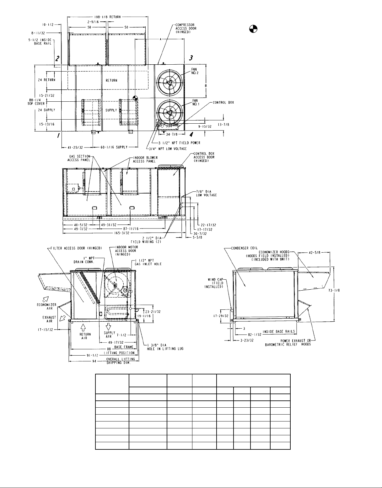
Fig. 2 — Base Unit Dimensions, 580G240-360
AB
3
⁄83-63⁄
5
⁄163-611⁄
5
⁄83-8 899 899 1232 1232
1
⁄83-85⁄
5
⁄83-8 899 899 1232 1232
1
⁄83-85⁄
5
⁄83-8 899 899 1232 1232
1
⁄83-85⁄
8
16
16
16
16
CORNER WEIGHT
(lb)
879 954 1220 1124
917 973 1218 1148
929 916 1240 1257
929 916 1240 1257
929 916 1240 1257
—3—
Page 4

NOTES:
1. Weights include economizer (STD).
2. Center of gravity.
3. Do not locate adjacent units with flue discharge facing
economizer inlet. Min. clearances to be:
Adjacent Units: 158-09
Top of Units: No Overhang
Condenser Coil: 48-09
Economizer Side: 68-09
Heat Side: 48-09
Filter Access Side: 108-09 (For Removal of Evaporator Coil)
4. For smaller service and operational clearances, contact Application Engineering department.
5. Dimensions are in inches.
6. For side supply/return applications a single return and
supply ductwork connection is recommended for covering both return and both supply openings.
UNIT SIZE
580H
OPERATING
WEIGHT
lb ft-in. ft-in. 1 2 3 4
240 350 4176 6- 0
240 525 4256 6- 1
300 350 4262 5- 9
300 525 4342 5-10
324 525 4262 5- 9
324 525 4342 5-10
360 350 4262 5- 9
360 525 4342 5-10
Fig. 3 — Base Unit Dimensions, 580H240-360
AB
3
⁄83-63⁄
5
⁄163-611⁄
5
⁄83-8 899 899 1232 1232
1
⁄83-85⁄
5
⁄83-8 899 899 1232 1232
1
⁄83-85⁄
5
⁄83-8 899 899 1232 1232
1
⁄83-85⁄
8
16
16
16
16
CORNER WEIGHT
(lb)
879 954 1220 1124
917 973 1218 1148
929 916 1240 1257
929 916 1240 1257
929 916 1240 1257
—4—
Page 5

CAUTION: NOTICE TO RIGGERS: ALL PANELS
MUST BE IN PLACE WHEN RIGGING.
NOTE: Rig with four cables and spread with two 92 in.
(2337 mm) spreader bars. Maintain a distance of 74 in.
(1880 mm) from top of unit to eyehook.
NOTE:
Add 32 lb (14.5 kg) for domestic crating.
Add 312 lb (142 kg) for export crating.
Add 220 lb (100 kg) for copper condenser coil.
Add 250 lb (113 kg) for power exhaust.
UNIT
580G,H
240 350 4176 1894
240 525 4256 1930 73.3 1862 42.7 1085
300 350
360 350
300 525
360 525
WEIGHT A B C
lb kg in. mm in. mm in. mm
72.4 1839 42.4 1072
4262 1933 69.6 1768 44.0 1118324 350
4342 1969 70.1 1781 44.3 1125324 525
87.68 2227
Fig. 4 — Rigging Label
—5—
Page 6

Table 1 — Specifications
UNIT 580G,H 240 300 324 360
NOMINAL CAPACITY (tons) 20 25 27 30
OPERATING WEIGHT (lb)
Unit
Al/Al* (Lo Heat/Hi Heat) 4176/4256 4262/4342 4262/4342 4262/4342
Al/Cu* (Lo Heat/Hi Heat) 4396/4476 4482/4562 4482/4562 4482/4562
Roof Curb (14-in. curb) 365 365 365 365
COMPRESSOR
Type Ckt 1 06D328 06D328 06D537 06D537
Ckt 2 06D818 06D328 06D328 06D537
Number of Refrigerant Circuits 22 2 2
Oil (oz) (Ckt 1, Ckt 2) 115, 88 115 ea. 115 ea. 115 ea.
REFRIGERANT TYPE R-22
Operating Charge (lb-oz)
Circuit 1† 25-0 25-0 25-0 25-0
Circuit 2 31-0 25-0 25-0 25-0
CONDENSER COIL Cross-Hatched
Quantity 11 1 1
Rows...Fins/in. 4...15 4...15 4...15 4...15
Total Face Area (sq ft) 33.3 33.3 33.3 33.3
CONDENSER FAN Propeller Type
Nominal Cfm 13,420 13,420 13,420 13,420
Quantity...Diameter (in.) 2...30 2...30 2...30 2...30
Motor Hp (1075 Rpm) 11 1 1
EVAPORATOR COIL Cross-Hatched
Rows...Fins/in. 4...15 4...15 4...15 4...15
Total Face Area (sq ft) 31.7 31.7 31.7 31.7
EVAPORATOR FAN Centrifugal Type
Quantity...Size (in.) 2...20x15 2...20x15 2...20x15 2...20x15
Type Drive Belt Belt Belt Belt
Nominal Cfm 8,000 10,000 11,000 12,000
Motor Hp 5 10** 15 7.5 10** 15 10 15** 20 10 15** 20
Motor Frame Size
Standard S184T S215T D254T S213T S215T D254T S215T D254T S256T S215T D254T S256T
High Efficiency S184T S215T S254T S213T S215T S254T S215T S254T S256T S215T S254T S256T
Motor Bearing Type Ball Ball Ball Ball
Maximum Allowable Rpm 1200 1200 1200 1200
Motor Pulley Pitch Diameter 4.8 4.4 5.7 5.4 6.1 5.5 4.4 4.9 5.9 4.4 5.7 5.9
Nominal Motor Shaft Diameter (in.) 1
Fan Pulley Pitch Diameter (in.) 12.4 8.6 9.1 12.4 11.1 8.7 9.4 8.1 8.7 9.0 9.1 8.7
Nominal Fan Shaft Diameter (in.) 115⁄
Belt, Quantity...Type
Belt, Length (in.)
Pulley Center Line Distance (in.) 16.0-18.7 15.6-18.4 15.0-17.9 15.6-18.4 15.0-17.9 15.6-18.4 15.0-17.9 15.6-18.4 15.0-17.9
Factory Speed Setting (rpm) 717 924 1096 773 962 1106 848 1059 1187 884 1096 1187
FURNACE SECTION
Rollout Switch Cutout Temp (F)†† 225 225 225 225
Burner Orifice Diameter
(in. ...drill size)
Natural Gas Std .111...34 .111...34 .111...34 .111...34
Liquid Propane Alt .089...43 .089...43 .089...43 .089...43
Thermostat Heat Anticipator
Setting (amps)
Stage 1 0.1 0.1 0.1 0.1
Stage 2 0.1 0.1 0.1 0.1
Gas Input (Btuh) Stage 1 Low 262,500 262,500 262,500 262,500
Efficiency (Steady State) (%) 82 82 82 82
Temperature Rise Range 15-45/35-65 15-45/35-65 15-45/35-65 15-45/35-65
Manifold Pressure (in. wg)
Natural Gas Std 3.5 3.5 3.5 3.5
Liquid Propane Alt 3.5 3.5 3.5 3.5
Gas Valve Quantity 22 2 2
Field Gas Connection Size
(in.-FPT)
HIGH-PRESSURE SWITCH (psig)
Cutout 426 426 426 426
Reset (Auto.) 320 320 320 320
LOW-PRESSURE SWITCH (psig)
Cutout 77 7 7
Reset (Auto.) 22 22 22 22
RETURN-AIR FILTERS
Quantity...Size (in.) 10...20x24x2 10...20x24x2 10...20x24x2 10...20x24x2
OUTDOOR-AIR FILTERS 8...16×25
Quantity...Size (in.) 4...20×25
POWER EXHAUST Direct Drive, 3-Speed, Single Phase Motor (Factory Wired for High Speed), Forward-Curved Fan
Motor, Quantity...Hp 4...1
Fan, Diameter...Width (in.) 11...10
High 394,000 394,000 394,000 394,000
Stage 2 Low 350,000 350,000 350,000 350,000
High 525,000 525,000 525,000 525,000
1
⁄
8
13⁄
8
15⁄
1...BX59622...BX51542...5VX530531...BX59621...5VX590592...5VX530532...BX52552...5VX500502...5VX530532...BX51542...5VX530532...5VX530
16
1.5 1.5 1.5 1.5
LEGEND
Al — Aluminum
Cu — Copper
*Evaporator coil fin material/condenser coil fin material.
†Circuit 1 uses the lower portion of condenser coil; Circuit 2 uses the upper portion. All
units have intertwined evaporator coils.
3
⁄89 Copper Tubes, Aluminum Lanced, Aluminum Pre-Coated, or Copper Plate Fins
3
⁄89 Copper Tubes, Aluminum Plate Fins, Intertwined Circuits
8
13⁄
8
13⁄
8
15⁄
8
13⁄
8
15⁄
8
15⁄
8
115⁄
16
**Motor and drive shown will deliver approximately 2.5 in. net external static. For more
fan motor data, see Table 2.
††Rollout switch is manual reset.
115⁄
16
13⁄
8
15⁄
8
15⁄
8
115⁄
16
53
—6—
Page 7

Table 2 — Evaporator Fan Motor Data
UNIT
MOTOR
SIZE
580G,H
240
300
324
360
NOTE: Motor shaft speed is 1750 rpm. The fan shaft diameter is 1
MOTOR
SHAFT
HP
10 1.38 924 2BK50 4.4 None-1.375 2B5V86 8.6 B-1.9375 (2) BX51 54 5.21
15 1.62 1096 2B5V56 5.7 B-1.625 2B5V90 9.1 B-1.9375 (2) 5VX530 53 6.00
7.5 1.38 773 BK60H 5.4 H-1.375 1B5V124 12.4 B-1.9375 BX59 62 6.48
10 1.38 962 1B5V60 6.1 H-1.375 1B5V110 11.1 B-1.9375 5VX590 59 7.37
15 1.62 1106 2B5V54 5.5 B-1.625 2B5V86 8.7 B-1.9375 (2) 5VX530 53 6.12
10 1.38 848 2BK50 4.4 None-1.375 2B5V94 9.4 B-1.9375 (2) BX52 55 5.27
15 1.62 1059 2B5V48 4.9 B-1.625 2B5V80 8.1 B-1.9375 (2) 5VX500 50 6.63
20 1.62 1187 2B5V58 5.9 B-1.625 2B5V86 8.7 B-1.9375 (2) 5VX530 53 7.31
10 1.38 884 2BK50 4.4 H-1.375 2B5V90 9.0 B-1.9375 (2) BX51 54 5.24
15 1.62 1096 2B5V56 5.7 B-1.625 2B5V90 9.1 B-1.9375 (2) 5VX530 53 6.00
20 1.62 1187 2B5V58 5.9 B-1.625 2B5V86 8.7 B-1.9375 (2) 5VX530 53 7.31
DIA.
(in.)
5 1.12 717 BK55 4.8 None-1.125 1B5V124 12.4 B-1.9375 BX59 62 5.10
FAN
SHAFT
SPEED
(rpm)
MOTOR
SHEAVE
MOTOR
SHEAVE
PITCH
DIAMETER
(in.)
DIAMETER
11
⁄16inches.
BUSHING
(in.)
A. Positioning
Provide clearance around and above unit for airflow, safety,
and service access (Fig. 2 and 3).
Do not install unit in an indoor location. Do not locate air
inlets near exhaust vents or other sources of contaminated
air.
For proper unit operation, adequate combustion and ventilation air must be provided in accordance with Section 5.3 (Air
for Combustion and Ventilation) of the National Fuel Gas Code,
ANSI Z223.1 (American National Standards Institute).
Although unit isweatherproof,guardagainst water from higher
level runoff and overhangs.
B. Roof Mount
Check building codes for weight distribution requirements.
FAN
SHEAVE
FAN
SHEAVE
PITCH
DIAMETER
(in.)
BUSHING
DIAMETER
(in.)
BELT
(QUANTITY)
OUTSIDE
BELT
LENGTH
BELT
TENSION
(lb at
.24 in.)
B. 580H Units
Remove shipping covers from supply and return air openings.Attachfield-suppliedductworkto unit. Use a single duct
over both return openings and a single duct over both supply openings. See Fig. 3 for duct opening dimensions. Secure
all ducts to the building structure. See Fig. 6. Use flexible
duct connectors between unit and ducts as required.
Install accessory barometric relief or power exhaust in
the field-fabricated return ductwork. Refer to Power
Exhaust/Barometric Relief Damper Hood section for more
information.
III. FIELD FABRICATE DUCTWORK
Secure all ducts to building structure. Use flexible duct connectors betweenunitandducts as required. Insulate and weatherproof all external ductwork, joints, and roof openings with
counter flashing andmasticinaccordance with applicable codes.
Ducts passing through an unconditioned space must be
insulated and covered with a vapor barrier.
To attach ductwork to roof curb, insert ductwork approximately 10 to 11 in. up into the curb. Connect ductwork to
14-gage roof curb material using sheet metal screws driven
from inside the duct.
WARNING:
For vertical supply and return units, tools
or parts could drop into ductwork and cause an injury.
Install 90 degree elbow turns in the supply and return
ductwork between the unit and the conditioned space.
If a 90 degree elbow cannot be installed, then grilles of
sufficient strength and density should be installed to
prevent objects from falling into the conditioned space.
IV. UNIT DUCT CONNECTIONS
A. 580G Units
Unit is shipped for through-the-bottom duct connections. Ductwork openings are shown in Fig. 2. Attach all ductwork to
roof curb. Air distribution is shown in Fig. 5. Refer to
installation instructions shipped with accessory roof curb for
more information.
Fig. 5 — Air Distribution — Thru-the-Bottom
Fig. 6 — Air Distribution — Thru-the-Side
—7—
Page 8

V. FLUE HOOD
Flue hood is shipped inside gas section of unit. To install, secure flue hood to access panel. See Fig. 7.
NOTE: When properly installed, flue hood will line up with
combustion fan housing. See Fig. 8.
Fig. 7 — Flue Hood Location
Fig. 9 — Condensate Drain Connections
(Typical Roof Curb or
Slab Mount Shown)
Condensate pans are sloped sothatwaterwillcompletelydrain
from the condensate pan to comply with indoor air quality
guidelines.
VII. GAS PIPING
Unit is equipped for use with natural gas. Installation must
conform with local building codes or, in the absence of local
codes, with the National Fuel Gas Code, ANSI Z223.1.
1
Install manual gas shutoff valve with a
⁄8-in. NPT pressure
tap for test gage connection at unit. Field gas piping must
include sediment trap and union. See Fig. 10.
WARNING:
Do not pressure test gas supply while
connected to unit. Always disconnect union before
servicing.
Fig. 8 — Combustion Fan Housing Location
VI. TRAP CONDENSATE DRAIN
See Fig. 2, 3, and 9 for drain location. Condensate drain is
open to the atmosphere and must be trapped. Install a trapped
drain at the drain location. One 1-in. NPT coupling is provided inside unit evaporator section for condensate drain connection. A trap at least 4-in. deep must be used. Trap must
be installed to prevent freeze-up.
Natural gas pressure at unit gas connection must not be less
than 5 in. wg or greater than 13.5 in. wg.
Size gas-supply piping for 0.5-in. wg maximum pressure drop.
Do not use supply pipe smaller than unit gas connection.
Fig. 10 — Field Gas Piping
—8—
Page 9

VIII. ELECTRICAL CONNECTIONS
A. Controls Options
The standard constant volume (CV) units, as shipped, are
operable as stand-alone units, using a standard (mechanical
or electronic) 2-stage heat, 2-stage cool thermostat.
Withastandard thermostat (programmable is optional), heating and cooling operation is set by space temperature. The
standard DDC (direct digital controls) are installed in the control box. The DDC control board diagram is shown in Fig. 11.
Features with Thermostat Control of Unit
• two-stage heating
• two-stage cooling
• control of unit using Y1, Y2, W1, W2, and G thermostat
inputs
• control of the indoor fan
• outdoor-air temperature/supply-air temperature
monitoring
• control of modulating economizer damper to provide free
cooling when outdoor conditions are suitable, using supplyair temperature as a control point
• control of the economizer damper and indoor fan to obtain
unoccupied free cooling
• provide power exhaust output to an external power
exhaust controller
• support a field test for field checkout
• control of 2 stages of CV power exhaust
• compressor time delay for power up and minimum off and
on times
An electronic expansion board may be field-installed to provide the following features:
• control of modulating economizer damper to maintain
indoor air quality (IAQ) when outdoor conditions are
suitable
NOTE: The IAQ sensor must be set for current output (4 to
20 mA). This requires removing the sensor cover and removing a jumper on the sensor. See Fig. 12.
• provide discrete inputs for fan status, filter status, fieldapplied status, and demand limit
• provide an output for the external alarm light indicator
• provide power exhaust fire outputs for directcontrolofpower
exhaust stages during fire or smoke control modes
• control of smoke control modes including evacuation, smoke
purge, pressurization, and fire shutdown (non-modulating
or modulating power exhaust required)
B. Power Wiring
Units are factory wiredforthevoltageshownon the unit nameplate. The main terminal block is suitable for use with aluminum or copper wires.
When installing units, provide a disconnect per NEC
(National Electrical Code) of adequate size (MOCP [maximum overcurrent protection]ofunitis on the informative plate).
All field wiring must comply with NEC and all local codes.
Size wire based on MCA (minimum circuit amps) on the unit
informative plate. See Fig. 13 for power wiring connections
to the unit power terminal block and equipment ground.
The main power terminal block is suitable for use with aluminum or copper wire. See Fig. 13. Units have circuit breakers for compressors, fan motors, and control circuit. If required
by local codes, provide an additional disconnect, per NEC and
local codes requirements, of adequate size (Table 3). Whenever external electrical sources are used, unit must be electrically grounded in accordance with local codes, or in absence
of local codes, with NEC, ANSI C1-latest year.
All field wiring must comply with NEC and local code
requirements.
C. Field Power Supply
Unit is factory wired for voltage shown on nameplate. See
Table 3 for electrical data.
Field wiring can be brought into the unit from bottom (through
basepan and roof curb) or through side of unit (corner post
next to control box).
1
⁄2-in. NPT knockout for field power wiring and a3⁄4-in.
A3
NPT knockout for 24-v control wiring are provided in base-
1
pan. In the side post, there are two 2
⁄2-in. knockouts for the
field power wiring. See Fig. 2 and 3. If control wiring is to be
7
brought in through the side of unit, a
⁄8-in. diameter hole is
provided in the condenser side post next to the control box.
If disconnect box is mounted to corner post, be careful not to
drill any screws into the condenser coil.
Routing Through Bottom of Unit
If wiring is brought in through bottom of unit, use fieldsupplied watertight conduit to run power wiring from base-
1
pan out through bottom 3
⁄2-in. hole to the disconnect box and
back into unit to the main control box.
1
Use strain relief going into control box through 2
⁄2-in. diameter hole provided. After wires are in unit control box, connect to power terminal block (see Power Wiring section
on this page).
Low-voltage wiring must be run in watertight conduit from
the basepan to control box and through 1-in. diameter hole
provided in bottom of unit control box. Field-supplied strain
relief must be used going into the box. After wiring is in control box, make connections to proper terminals on terminal
blocks (see Field Control Wiring section on page 11).
Install conduit connector in unit basepan or side panel openings provided. Route power and ground lines through connector to connections in unit control box as shown on unit
wiring diagram and Fig. 13.
Routing Through Side of Unit
Route power wiring in field-supplied watertight conduit into
1
unit through 2
⁄2-in. hole. Strain relief (field supplied) must
be used in hole.
Use field-supplied strain relief going into control box through
1
⁄2-in. diameter hole provided. After wires are in unit con-
2
trol box, connect to power terminal block (see Power Wiring
section on this page).
Bring low-voltage control wiring through factory-drilled
7
⁄8-in. diameter hole in condenser side post. Use strain relief
going into
7
⁄8-in. diameter hole in bottom of unit control box.
After wiring is in control box, make connection to proper terminals on terminal blocks (see Field Control Wiring section
on page 11).
WARNING:
The unit must be electrically grounded
in accordance with local codes and NEC ANSI/NFPA70
(National Fire Protection Association).
—9—
Page 10

—10—
Fig. 11 — Control Board Diagram
LEGEND
COM — Common R—Relay
D—Diode SIO — Serial Input/Output
LED — Light-Emitting Diode SW — Switch
N.C. — Normally Closed T—Terminal
N.O. — Normally Open
*Where X is the unit control software version number (1 or 2).
Page 11

JUMPER CONNECTION
FOR VOLTAGE OUTPUT
JUMPER CONNECTION
FOR CURRENT OUTPUT
Fig. 12 — Indoor Air Quality Sensor Configuration
3. Cap orange wire.
4. Splice red wire and black unit power wire. Cap wires.
IMPORTANT: Becertain unused wires are capped. Failure to
do so may damage the transformers.
D. Field Control Wiring
Install an approved accessory thermostat. Control box diagram is shown in Fig. 14.
Thermostat Wiring
Install an approved accessory thermostat assembly (per cur-
rent price pages) according to the installation instructions included with the accessory, or these instructions. Locate thermostat assembly on a solid wall in the conditioned space to
sense average temperature.
Route thermostat cable or equivalent single leads of
no. 18AWG (American Wire Gage) colored wire from subbase
terminals to low-voltage connections as shown on unit label
wiring diagram and in Fig. 15.
NOTE: For wire runs up to 50 ft, use no. 18 AWG insulated
wire (35 C minimum). For 50 to 75 ft, use no. 16 AWG
insulated wire (35 C minimum). For over 75 ft, use no. 14
AWG insulated wire (35 C minimum). All wire larger than
no. 18 AWG cannot be directly connected to the thermostat
and will require a junction box and splice at the thermostat.
Set heat anticipators settings to .1 for all voltages. Settings
may be changed slightly to provide a greater degree of comfort for a particular installation.
LEGEND
EQUIP — Equipment NEC — National Electrical Code
GND — Ground TB — Terminal Block
NOTE: TB1 Maximum wire size is 500 MCM.
Fig. 13 — Field Power Wiring Connections
Operating voltage to compressor must be within voltage range
indicated on unit nameplate. On 3-phase units, voltages between phases must be balanced within 2% and the current
must be balanced within 10%.
Use the formula in Table 3 to determine the percentage of
voltage imbalance.
IMPORTANT: If the supply voltage phase imbalance is
more than 2%, contact your local electric utility company
immediately.
Unit failure as a result of operation on improper line voltage
or excessive phase imbalance constitutes abuse and may cause
damage to electrical components.
On 208/230-v units, transformer no. 1 is wired for 230-v. If
208/230-v unit is to be run with 208-v power supply ,the transformer must be rewired as follows:
1. Remove cap from red (208-v) wire.
2. Remove cap from spliced orange (230-v) wire. Disconnect orange wire from black unit power wire.
LEGEND
C—Compressor/Contactor
CB — Circuit Breaker
DIP — Dual In-Line Package
FU — Fuse
HR — Heater Relay
IF — Indoor Fan
OF — Outdoor Fan
PEC — Power Exhaust Controller
TB — Terminal Block
TRAN — Transformer
Fig. 14 — Control Box Diagram
—11—
Page 12

Table 3— Electrical Data — 580G,H240-360
UNIT
SIZE
580G,H
240
300
FLA — Full Load Amps
HACR — Heating, Air Conditioning and Refrigeration
IFM — Indoor (Evaporator) Fan Motor
LRA — Locked Rotor Amps
MCA — Minimum Circuit Amps
MOCP — Maximum Overcurrent Protection
NEC — National Electrical Code
OFM — Outdoor (Condenser) Fan Motor
RLA — Rated Load Amps
*Fuse or HACR circuit breaker.
NOTES:
1. In compliance with NEC requirements for multimotor and combination load equipment (refer to NEC Articles 430 and 440), the overcurrent protective device for the unit shall be fuse or HACR breaker.
Canadian units may be fuse or circuit breaker.
2. Unbalanced 3-Phase Supply Voltage
Never operate a motor where aphaseimbalance in supply voltage is
greater than 2%.
voltage imbalance.
% Voltage Imbalance
= 100 x
NOMINAL
VOLTAGE
(3 Ph 60 Hz)
208/230 187 254 39.1 228 25.6 160 2 1 5.3
460 414 508 19.9 114 11.5 80 2 1 2.7
575 518 632 16.0 91 9.6 64 2 1 2.4
208/230 187 254 39.1 228 39.1 228 2 1 5.3
460 414 508 19.9 114 19.9 114 2 1 2.7
575 518 632 16.0 91 16.0 91 2 1 2.4
max voltage deviation from average voltage
VOLTAGE
RANGE
Min Max RLA LRA RLA LRA Qty Hp
LEGEND
or
Use the following formula to determine the percent
average voltage
COMPRESSOR
No. 1 No. 2
OFM IFM
FLA
Hp FLA FLA LRA FLA MCA MOCP*
(ea)
5
10
15
5 7.6
10 14.0
15 21.0
5 6.1
10 11.0
15 17.0
7.5
10
15
7.5 11.0
10 14.0
15 21.0
7.5 9.0
10 11.0
15 17.0
EXAMPLE: Supply voltage is 460-3-60.
Determine maximum deviation from average voltage.
(AB) 457 − 452=5v
(BC) 464 − 457=7v
(AC) 457 − 455=2v
Maximum deviation is 7 v.
Determine percent voltage imbalance.
% Voltage Imbalance = 100 x
This amount of phase imbalance is satisfactory as it is below the
maximum allowable 2%.
IMPORTANT: If the supply voltage phase imbalance is more than
2%, contact your local electric utility company immediately.
POWER
EXHAUST
16.7/
— — 0.96 101.8/100.3 125/125
15.2
23.6 41.6 0.96 125.4/123.9 150/150
30.8/
— — 0.96 115.9/113.1 150/150
28.0
23.6 41.6 0.96 139.5/136.7 175/175
46.2/
— — 0.96 131.3/127.1 150/150
42.0
23.6 41.6 0.96 154.9/150.7 175/175
— — 0.50 49.4 60
12.6 23.6 0.50 62.0 80
— — 0.50 55.8 70
12.6 23.6 0.50 68.4 80
— — 0.50 62.8 80
12.6 23.6 0.50 75.4 90
— — 0.50 40.5 50
12.6 23.6 0.50 53.1 60
— — 0.50 45.4 60
12.6 23.6 0.50 58.0 70
— — 0.50 51.4 60
12.6 23.6 0.50 64.0 80
24.2/
— — 0.96 122.8/120.6 150/150
22.0
23.6 41.6 0.96 146.4/144.2 175/175
30.8/
— — 0.96 129.4/126.6 150/150
28.0
23.6 41.6 0.96 153.0/150.2 175/175
46.2/
— — 0.96 144.8/140.6 175/175
42.0
23.6 41.6 0.96 168.4/164.0 200/200
— — 0.50 61.2 80
12.6 23.6 0.50 73.8 90
— — 0.50 64.2 80
12.6 23.6 0.50 76.8 90
— — 0.50 71.2 90
12.6 23.6 0.50 83.8 100
— — 0.50 49.8 60
12.6 23.6 0.50 62.4 70
— — 0.50 51.8 60
12.6 23.6 0.50 64.4 80
— — 0.50 57.8 70
12.6 23.6 0.50 70.4 80
AB = 452 v
BC = 464 v
AC = 455 v
Average Voltage =
COMBUSTION
FAN MOTOR
= 1.53%
452 + 464 + 455
1371
=
3
= 457
7
457
POWER SUPPLY
3
—12—
Page 13

Table 3— Electrical Data — 580G,H240-360 (cont)
UNIT
SIZE
580G,H
324
360
FLA — Full Load Amps
HACR — Heating, Air Conditioning and Refrigeration
IFM — Indoor (Evaporator) Fan Motor
LRA — Locked Rotor Amps
MCA — Minimum Circuit Amps
MOCP — Maximum Overcurrent Protection
NEC — National Electrical Code
OFM — Outdoor (Condenser) Fan Motor
RLA — Rated Load Amps
*Fuse or HACR circuit breaker.
NOTES:
1. In compliance with NEC requirements for multimotor and combination load equipment (refer to NEC Articles 430 and 440), the overcurrent protective device for the unit shall be fuse or HACR breaker.
Canadian units may be fuse or circuit breaker.
2. Unbalanced 3-Phase Supply Voltage
Never operate a motor where aphaseimbalance in supply voltage is
greater than 2%.
voltage imbalance.
% Voltage Imbalance
= 100 x
NOMINAL
VOLTAGE
(3 Ph 60 Hz)
208/230 187 254 57.1 266 39.1 228 2 1 5.3
460 414 508 25.6 120 19.9 114 2 1 2.7
575 518 632 20.5 96 16.0 91 2 1 2.4
208/230 187 254 57.1 266 57.1 266 2 1 5.3
460 414 508 25.6 120 25.6 120 2 1 2.7
575 518 632 20.5 96 20.5 96 2 1 2.4
max voltage deviation from average voltage
VOLTAGE
RANGE
Min Max RLA LRA RLA LRA Qty Hp
LEGEND
or
Use the following formula to determine the percent
average voltage
COMPRESSOR
No. 1 No. 2
OFM IFM
FLA
Hp FLA FLA LRA FLA MCA MOCP*
(ea)
10
15
20
10 14.0
15 21.0
20 27.0
10 11.0
15 17.0
20 22.0
10
15
20
10 14.0
15 21.0
20 27.0
10 11.0
15 17.0
20 22.0
EXAMPLE: Supply voltage is 460-3-60.
Determine maximum deviation from average voltage.
(AB) 457 − 452=5v
(BC) 464 − 457=7v
(AC) 457 − 455=2v
Maximum deviation is 7 v.
Determine percent voltage imbalance.
% Voltage Imbalance = 100 x
This amount of phase imbalance is satisfactory as it is below the
maximum allowable 2%.
IMPORTANT: If the supply voltage phase imbalance is more than
2%, contact your local electric utility company immediately.
POWER
EXHAUST
30.8/
— — 0.96 151.9/149.1 200/200
28.0
23.6 41.6 0.96 175.5/172.7 225/225
46.2/
— — 0.96 167.3/163.1 200/200
42.0
23.6 41.6 0.96 190.9/186.7 225/225
59.4/
— — 0.96 180.5/175.1 225/225
54.0
23.6 41.6 0.96 204.1/198.7 250/250
— — 0.50 71.3 90
12.6 23.6 0.50 83.9 100
— — 0.50 78.3 100
12.6 23.6 0.50 90.9 110
— — 0.50 84.3 100
12.6 23.6 0.50 96.9 110
— — 0.50 57.4 70
12.6 23.6 0.50 70.0 90
— — 0.50 63.4 80
12.6 23.6 0.50 76.0 90
— — 0.50 68.4 80
12.6 23.6 0.50 81.0 100
30.8/
— — 0.96 169.9/167.1 225/200
28.0
23.6 41.6 0.96 193.5/190.7 250/225
46.2/
— — 0.96 185.3/181.1 225/225
42.0
23.6 41.6 0.96 208.9/204.7 250/250
59.4/
— — 0.96 198.5/193.1 250/250
54.0
23.6 41.6 0.96 222.1/216.7 275/250
— — 0.50 77.0 100
12.6 23.6 0.50 89.6 110
— — 0.50 84.0 100
12.6 23.6 0.50 96.6 110
— — 0.50 90.0 110
12.6 23.6 0.50 102.6 125
— — 0.50 61.9 80
12.6 23.6 0.50 74.5 90
— — 0.50 67.9 80
12.6 23.6 0.50 80.5 100
— — 0.50 72.9 90
12.6 23.6 0.50 85.5 100
AB = 452 v
BC = 464 v
AC = 455 v
Average Voltage =
COMBUSTION
FAN MOTOR
= 1.53%
452 + 464 + 455
1371
=
3
= 457
7
457
POWER SUPPLY
3
—13—
Page 14

TOP
FLANGE
Fig. 15 — Field Control Thermostat Wiring
IX. OUTDOOR-AIR INLET ASSEMBLY
A. Economizer
NOTE: If accessory power exhaust or barometric relief pack-
ages are being added to the unit, install power exhaust or
barometric relief before installing economizer hoods.
BLACK
SEAL
STRIP
HOOD SIDE
Fig. 16 — Adding Seal Strip to Top of Hood Sides
Economizer Hood Assembly
The economizer hood is shipped in a package secured to the
outside of the unit and must be field assembled. There are
2 hoods on every unit. The 580H units are side supply and
side return. The return duct limits access to economizer
filters from below. Filter tracks (mounting angle without tabs)
must be installed correctly to allow access to economizer
filters from each side.
NOTE: Before assembly of the economizer hood, check along
the outer edges of the economizer assembly for any seal strip
protruding past the flanges. Trim the excess seal strip so that
it is flush with the economizer assembly flanges.
Perform the following procedure to assemble the economizer
hood:
a. Apply black seal strip (provided in package) to out-
1.
side top edge of hood sides. Wrap seal strip over to
cover top flange (4 hood sides). Make certain seal strip
1
covers screw holes.Allowstrip to overhang
⁄8in. past
end opposite mounting flange. See Fig. 16.
b. Assemble hood sides, top, and cross member with gas-
keted screws provided. See Fig. 17.
c. Attach 10 green speed clips (provided) to hood top.
d. Apply black seal strip to mountingflanges(coverholes)
of hood sides. See Fig. 18.
NOTE: Each hood assembly has a slotted side that should be
adjacent to the other hood when mounted to the unit.
e. Apply black seal strip to hood top mounting flange.
Seal strip of hood top mounting flange must press
against seal strip of hood side mounting flanges. See
Fig. 19.
f. Add gray foam strip (provided) to cross members at
bottom tray. See Fig. 20.
NOTE: Left side economizer hood has mounting angle withouttabs and
filter track assembled end on opposite side.
Fig. 17 — Economizer Hood Assembly
(Right-Side Economizer Hood Shown)
Exhaust Mounting Details
g. Place gray foam strip on inside of slotted hood side
between filter and cross member opposite mounting
end. See Fig. 21.
h. Attach gray foam strip to blockoff baffle on outer face
area of flange. See Fig. 22.
2. Remove the screws on each end and along top of damper
assembly of unit. Remove top 2 screws on each side of
filter panel under damper assembly. Set hood assembly
in place and attach to unit using these screws.
3. Attach accessory enthalpy bracket on hood side furthest from control box end. Locate bracket on inside
upper righthandcornerusing hood mounting holes. Mount
outdoor-air thermistor to enthalpy bracket (if purchased).Attachandwireenthalpy assembly. Place quick
connects on enthalpy wires.
—14—
Page 15

P
HOOD SIDE
(SLOTTED)
MOUNTING
FLANGE
HOOD SIDE
Fig. 18 — Adding Seal Strip to Mounting Flange
of Hood Sides
HOOD SIDE
HOOD TO
HOOD
TOP
Fig. 21 — Adding Foam Strip to Hood Side
BLOCKOFF BAFFLE
Fig. 19 — Add Seal Strip to Hood Top Mounting Flange
GRAY FOAM STRIP
CROSS MEMBER
GRAY FOAM STRIP
Fig. 22 — Adding Foam Strip To
Blockoff Baffle
Fig. 20 — Adding Foam Strip to Cross Member
—15—
Page 16

4. Remove screws along bottom of damper assembly. Locate and mount blockoff baffle using these screws.
5. Assemble 2 filter tracks side-by-side with the assembled ends together.
a. Attach mounting angle (without tabs) to the as-
6.
sembled end of the filter track. See Fig. 23.
b. Attach 6 green clips (provided) to mounting angles.
Engagement section of clip faces inside of rack.
c. Attach remaining mounting angle (with tabs) to other
end of the filter track with no. 10 screws provided.
See Fig. 24.
a. Place filter track assembly in bottom of hood by plac-
7.
ing tabbed end into slotted side (with tab on bottom)
and attaching opposite end to hood with speed clips
and gasketed screws provided. Tabscan be hand bent
after inserted into the side.
NOTE: The filter track assembly end with screws should face
away from the other hood when mounted on the unit.
NOTE: Tabs from both filter tracks will be in the same space.
After one filter track has been inserted into board, bend the
tabs so they will not interfere with installation of the second
hood.
b. Attach black seal strip to filter cover.Sealstripshould
be applied to flange (coveringholes)andcenteroflarge
flange. See Fig. 25.
8. Slide two 20 x 25-in. filters into cross members of hood
assembly. Attach filter cover over filters with screws and
speed clips provided.
Minimum Damper Position Setting
Setting of the outdoor air damper position is performed in
conjunction with a shortened version of the field run test. This
is performed by first opening DIP switch no. 4 then no. 6.
The outdoor-air damper closes. The control allows 90 seconds
for the damper to close in case it is in the full open position.
Next, the indoor-fan contactor will energize. The outdoor air
damper will remain at 0% for 30 seconds. It will then move
to the 10% position for another 30 seconds. This will be
repeated at every 10% increment for 30 seconds until the
damper reaches 100% open. Close DIP switch no. 4 during
the 30 seconds immediately after the desired outdoor air minimum damper position. The 30-second time period is to allow
time where DIP switch no. 4 can be closed. The default value
of the minimum outdoor air damper position is 20%. If the
desired minimum position is 30%, allow the damper position to go to 10% for 30 seconds, then 20% for 30 seconds,
and when it reaches 30% close DIP switch no. 4 during the
30-second period following the 30% position.
The minimum outdoor air damper position is now set. Close
DIP switch no. 6.
B. Economizer Settings
Accessory Enthalpy Control (Fig. 26)
The control (HH57AC077) is mounted in the economizer hood.
See Fig. 17. The enthalpy setting adjustment is on the enthalpy control. For maximum benefit of outdoor air, set enthalpy sensor control to A. See Fig. 27 and 28.
Enthalpy Control Installation
The outdoor air enthalpycontrolisinstalledonthe inside panel
of the outdoorairhood.The enthalpy control should be mounted
when the outdoor air hoods are assembled. To install the control, perform the following procedure:
1. Turn off all power. Ensure disconnect is locked out.
2. Remove the economizer inlet filters from the bottom of
the right hand economizer hood. See Fig. 29.
MOUNTING ANGLE
(WITHOUT TABS)
FILTER TRACK
ASSEMBLY
Fig. 23 — Mounting Angle (Without Tabs)
Attached to Filter Track Assembly
MOUNTING ANGLE
(WITH TABS)
Fig. 24 — Mounting Angle (With Tabs)
Attached to Filter Track Assembly
BLACK SEAL STRIP
(CENTERED)
FILTER COVER
Fig. 25 — Attaching Seal Strip to Filter Cover
—16—
Page 17

HH57AC077
ENTHALPY CONTROL
NOTE: Switches shown in high enthalpy state. Terminals 2 and 3 close on enthalpy decrease.
Fig. 27 — Wire Connections for Solid-State
Enthalpy Control (HH57AC077)
C7400A1004
+
HH57AC078
ENTHALPY SENSOR (USED WITH
ENTHALPY CONTROLFOR DIFFERENTIAL ENTHALPY OPERATION)
Fig. 26 — Enthalpy Control and Sensor
3. Mount the outdoor air enthalpy sensor inside the right
economizer hood on the right side panel of the hood,
adjacent to the outdoor-air thermistor.
4. Locate the red, violet, and brown wires near the out-
door air thermistor. Remove the splice from the red and
violet wires. Remove the cap from the brown wire.
1
5. Install a
⁄4-in. push on terminal (field-supplied) on the
violet and brown wires.
1
6. Connect a
⁄4-in. push on terminal (field-provided) to one
end of a 18-gage, 6-in. jumper wire (field-provided). Con-
1
nect the other end to the red wire and attach a
⁄4-in.
push on connector (field-provided).
7. Connect the red wire with the jumper to terminal TR1.
Connect the jumper to terminal 2. Connect the brown
wire to terminal TR. Connect the violet wire to terminal 3. All connections are on the enthalpy control.
8. Replace the economizer filters.
9. Return power to unit.
Accessory Differential Enthalpy Control (Fig. 26)
The control (HH57AC077), in conjunction with the accessory
enthalpy sensor (HH57AC078), controls economizer operation according to the differential enthalpy. The control is
mounted in the economizer hood. The sensor is mounted in
the return duct (580G) or the return air plenum (580H).
Differential Enthalpy Sensor Installation
To install the control, perform the following procedure:
1. Turn off all power. Ensure disconnect is locked out.
2. Remove the economizer inlet filters from the bottom of
the right hand economizer hood.
3. Remove the factory-installed, 620-ohm jumper between terminals SR and + on the enthalpy control
located inside the outdoor air hood.
4. Connect the violet wire from the enthalpy sensor kit to
the + terminal on the enthalpy control. Connect the blue
wire from the enthalpy sensor kit to the SR terminal
on the terminal control.
CONTROL
CURVE
RH — Relative Humidity
CONTROL POINT
(APPROX. DEG.)
A 73 (23)
B 70 (21)
C 67 (19)
D 63 (17)
AT 50% RH
Fig. 28 — Psychrometric Chart for Enthalpy Control
5. Turntheenthalpycontrolsetpointpotentiometerclockwise past the ‘‘D’’setting on the enthalpy control to configure the control to operate on differential enthalpy.
6. Remove the return-air enthalpy sensor from the accessory package. Using the screws provided, mount the
sensor inside the return duct near the unit. Do not
locate the control too far from the unit, or the wires
will not reach from the sensor to the control. On 580H
units, the enthalpy sensor can be installed in the
return air section of the unit, under the return air
dampers.
7. Route the wires from the enthalpy sensor to the
return air enthalpy control through the holes on the
inside of the hinged filter access panel. The holes are
blocked by plug buttons which should be removed.
—17—
Page 18

8. Use field-supplied wire ties to attach the violet wire to
the + terminal and the blue wire to the SR terminal.
9. Replace economizer filters.
10. Return power to unit.
Disable Economizer
For applications where the economizer will not be used
(areas of high humidity), the economizer should be disabled.
To disable the economizer, perform the following:
1. Turn off power. Lock out disconnect.
2. Locate the OAT(outdoorairthermistor)intherighthand
outdoor air damper area.
3. Locate the splice connecting the violet wire coming from
T24 on the base module board to the red wire coming
from T29 on the base module board. Remove the wire
nut and break the red to violet wire splice.
4. Cap off both wires. When the connection is broken, the
base module is fooled into thinking that the enthalpy is
not acceptable and economizer operation is disabled.
NOTE: Economizer operation can also be disabled by disconnecting the OAT. This is not recommended due to the fact
that Unoccupied Free Cooling, IAQ Purge, and Low Ambient
Fan Cycle Control are also disabled. An OAT failure alarm
will also be issued.
X. POWER EXHAUST/BAROMETRIC RELIEF DAMPER HOOD
All electrical connections have been made and adjusted at the
factory. The power exhaust blowers and barometric reliefdampers are shipped assembled and tilted back into the unit for
shipping. Brackets and extra screws are shipped in shrink
wrap around the dampers. If ordered, each unit will have
4 power exhaust blowers and motors or 4 barometric relief
dampers.
1. Remove 9 screws holding each damper assembly in place.
See Fig. 30. Each damper assembly is secured with
3 screws on each side and 3 screws along the bottom.
Save screws.
2. Pivot each damper assembly outward until edges of
damper assembly rest against inside wall of unit.
CAUTION:
Be careful when tilting blower assembly.
Hoods and blowers are heavy and can cause injury if
dropped.
3. Secure each damper assembly to unit with6screwsacross
top (3 screws provided) and bottom (3 screws from
Step 1) of damper.
4. With screws saved from Step 1, install brackets on each
side of damper assembly.
5. Remove tape from damper blades.
NOTE: Partitionsshown indicate both sidesupply (580H)
and vertical supply (580G) units.
Fig. 29 — Economizer Details
—18—
Page 19

NOTES:
1. Unless otherwise specified, all dimensions are to outside of part.
2. Dimensions are in inches.
Fig. 30 — Barometric Relief Damper and Power Exhaust Mounting Details
XI. ACCESSORIES
After all the factory-installed options have been adjusted, install all field-installed accessories. Refer to the accessory installation instructions included with each accessory.
A. MotormasterT III Control Installation
Install Field-Fabricated Wind Baffles
Wind baffles must be field-fabricated for all units to ensure
proper cooling cycle operation at low-ambient temperatures.
See Fig. 31 for baffle details. Use 20-gage, galvanized sheet
metal, or similar corrosion-resistant metalforbaff les.Use fieldsupplied screws to attach baffles to unit. Screws should be
1
⁄4-in. diameter and5⁄8-in. long. Holes for wind baffles are pre-
punched in the unit sheet metal.
CAUTION:
To avoid damage to the refrigerant coils
and electrical components, use recommended screw sizes
only.
The wind baffles attach to flanges formed on the outer sheet
metal of the unit where the condenser coil tube sheets
attach.
Install Motormaster III Controls
Only one Motormaster III control is required per unit.
Motor — The circuit no. 1 (lead compressor) outdoor-fan
motor (OFM) will need to be changed out in the field to
accommodate the Motormaster III accessory. The replacement motor part no. is HD52AK652.
The no. 1 compressor is located at the left side of the unit
looking from the compressor end.
Sensor — Install the sensor for thermistor input control in
the location shown in Fig. 32. Connect sensor leads to the
violet and grey control signal leads on the Motormaster III
control.
Signal Selection Switch — Remove the cover of the Motormaster III control. Set the switch to accept the thermistor
sensor input signal. Set the frequency to match the unit power
supply (60 Hz).
1
BOTH SIDES
18
77.7
0.312 DIA
HOLES
61
17.167
BETWEEN
HOLES
(TYPICAL)
4.62
NOTE: All dimensions are in inches. Material: 20 gage galvanized steel
or other non-corrosive material.
CROSS-BREAK
78.7
0.5
Fig. 31 — Motormaster III Baffle Details
Motormaster III Control — The recommended mounting
location is in the indoor fan section, mounted on the panel
that separates the indoor and outdoor sections.
Electrical Connections
WARNING:To avoid possibility of electrical shock and
personal injury, turn off all power to unit before making electrical connections.
When replacing the OFM, reconnect the black, yellow, and
blue wires from the outdoor fan contactor to the black, yellow, and blue wires of the Motormaster III control. Run new
wires from the red, orange, and brown wires to the leads of
the new OFM. Connect the green wire from the control to
ground.
NOTE: On all 575-v units, 2 transformers (part no.
HT01AH851) must be used for each Motormaster III control
to lower the supply voltage to the control to 460-v. Transformers can be mounted anywhere outside the control box.
—19—
Page 20

Fig. 32 — Low Ambient Kit Sensor Location
PRE-START-UP
WARNING:
ings could result in serious personal injury:
1. Follow recognized safety practices and wear protective goggles when checking or servicing refrigerant system.
2. Do not operate compressor or provide any electric
power to unit unless compressor terminal cover is
in place and secured.
3. Do not remove compressor terminal cover until all
electrical sources have been disconnected.
4. Remove and reclaim refrigerant from system before touching or disturbing anything inside terminal box if refrigerant leak is suspected around
compressor terminals.
5. Never attempt to repair soldered connection while
refrigerant system is under pressure.
6. Do not use torch to remove any component. System contains oil and refrigerant under pressure.
To remove a component, wear protective goggles
and proceed as follows:
a. Shut off electrical power to unit.
b. Remove and reclaim refrigerant from system.
c. Cut component-connecting tubing with tubing
d. Carefully unsweat remaining tubing stubs when
Proceed as follows to inspect and prepare the unit for initial
start-up:
1. Remove all access panels.
2. Read and follow instructions on all WARNING, CAUTION, andINFORMA TIONlabels attached to, or shipped
with, unit.
Failure to observe the following warn-
cutter and remove component from unit.
necessary. Oil can ignite when exposed to torch
flame.
3. Make the following inspections:
a. Inspect for shipping and handling damages such as
broken lines, loose parts, disconnected wires, etc.
b. Inspect for oil at all refrigerant tubing connections
and on unit base. Detecting oil generally indicates
a refrigerant leak. Leak-test all refrigerant tubing
connections usingelectronicleakdetector,halidetorch,
or liquid-soap solution.
c. Inspect all field- and factory-wiring connections. Be
sure that connections are completed and tight.
d. Inspect coil fins. If damaged during shipping and
handling, carefully straighten fins with a fin comb.
4. Verify the following conditions:
a. Make sure that condenser-fan blades are correctly
positioned in fan orifices. Blades should clear fan
motor and fan orifice ring.
b. Make sure that return-air filters and outdoor-air
inlet screens are in place.
c. Make sure that the condensate trap is filled with
water to ensure proper drainage.
d. Make sure that all toolsandmiscellaneouslooseparts
have been removed.
5. Loosen the compressor holddown bolts until sideways
movement of the washer under each holddown bolt can
be obtained. Do not loosen completely as bolts are selflocking and will maintain adjustment. Open compressor valves.
6. Make sure refrigerant service port caps are tight. Each
refrigerant system has one suction port located in the
top of the compressor motor casing. All units also have
one service port on the liquid line valve and one on the
compressor discharge valve.
7. Crankcase heaters are energized as long as there is
power to the unit, except when the compressors are
operating.
IMPORTANT: Unit power must be on for 24 hours prior to
start-up. Otherwise, damage to compressor may result.
8. Ensure that the suction, discharge, and liquid line service valves are open. Damage to the compressor could
result if they are left closed.
9. Check Direct Digital Controls DIP (dual-in-line package) switch configuration. The Direct Digital Control
(DDC) board must be configured for each application. The DDC board is configured through the DIP
switches located on the board. There are 8 DIP switches
which configure 8 differentapplicationsoftheDDC.See
Table 4. DIP switch 1 is on the left of the block. DIP
switch 8 is on the right of the block. To open a DIP
switch, push the switch up with suitable tool (smallblade screwdriver).To close a DIPswitch,push the switch
down. Factory settings are shown in Table 5.
The DIP switch configurations for the unit control software are as follows:
• DIP switch 1 should be set to closed (CV operation)
• DIP switch 2 should be set to closed (thermostat)
• DIP switch 3 is used to enable expansion board
operation
• DIP switch 4 is used to field test the unit
• DIP switch 5 is used to specify the type of power
exhaust
—20—
Page 21

Table 4 — DIP Switch Configuration
SETTING 1 2 3 4 5 6 7 8
Time GuardT
Override ON
IN CONJUNCTION
WITH FIELD TEST —
Set Minimum
Damper Position
Time Guard
Override OFF
Gas Heat
Electric Heat
Heat Pump
Operation
Air Conditioner
Operation
OPEN ——
CLOSED CV
LEGEND
CV — Constant Volume
Thermostat
Used
Expansion
Board
Operation
Base Control
Board Only
Field
Test
ON
Field
Test
OFF
Modulated
Power
Exhaust
CV
Power
Exhaust
NOTES:
1. TheOPEN side of the DIPswitch is marked ‘‘OPEN.’’When the rocker
switch is on the ‘‘OPEN’’ side of the switch, the switch is open.
2. When the unit is being field-tested (DIP switch 4 to OPEN), the function of DIPswitch 6 changes andit is used to settheminimum damper
position.
Table 5 — DIP Switch Factory Settings
UNIT 12345678
580G,H Closed Closed Closed Closed Closed Closed Open Closed
• DIP switch 6 configures the Time Guard override and,
when used with the field test function, sets the minimum damper position
• DIP switch 7 configures the unit for gas heat or electric heat
• DIP switch 8 configures the unit for heat pump or
air conditioner operation
10. Adjust economizer. Check that outdoor-air damper is
closed and return-air damper is open.
IMPORTANT: Unit power must be on for 24 hours prior to
start-up. Otherwise, damage to compressor may result.
11. The optional non-modulating power exhaust is a two-
stage design where the operation of the exhaust fans
is linked to economizer position. When the supply fan
is running and the economizer is 25% open, the base
module closes contacts, activating 2 exhaust fans. When
the economizer position reaches75%open,thebase module activates the other 2 exhaust fans. The fans will
turn off when the economizer closes below the same
points.
START-UP
I. COOLING SECTION START-UP AND ADJUSTMENTS
CAUTION:
Complete the required procedures given
in the Pre-Start-Up section on page 20 before starting
the unit.
Do not jumper any safety devices when operating the
unit.
Do not operate the compressor when the outdoor temperature is below 40 F (unless accessory low ambient
kit is installed).
Do not rapid-cycle the compressor. Allow 5 minutes
between ‘‘on’’ cycles to prevent compressor damage.
A. Checking Cooling Control Operation
Start and check the unit for proper cooling control operation
as follows:
Place SYSTEM switch in COOL position and FAN switch in
AUTO. position. Set cooling control below room temperature.
Observe that compressor, condenser fan motor, and evaporator blower motors start. Observe that cooling cycle shuts down
when control setting is satisfied.
B. Cooling Sequence of Operation
On power up, the control module will activate the initialization software. The initialization software reads DIP switch
no. 1 to determine it is in the closed position. Next, DIP switch
no. 2 is read to determine it is closed for thermostat operation. The initialization sequence clears all alarms and alerts;
re-maps the input/output database for operation; sets maximum heat stages to 2; and sets maximum cool stages to 3.
Power up takes a random 1 to 63 seconds plus 5 minutes.
The TSTAT function performs a thermostat based control by
monitoring Y1, Y2, W1, W2 and G inputs. These functions
control stages: cool1, cool2, heat1, heat2 and the indoor fan,
respectively.
The control module will operate economizer and run diagnostics to monitor alarms at all times.
If the thermostat energizes the G input, the control module
will turn on the indoor fan and open the economizer dampers
to minimum position. If thermostats are used to deenergize
the G input, the control module will turn off the indoor fan
and close the economizer dampers.
When cooling, G must be energized before cooling can operate. The control module determines if outdoor conditions are
suitable for economizer cooling. For the economizer to function for outside air cooling: the enthalpy must be below the
enthalpy set point; the outdoor-air temperature must be equal
to or less than 65 F; the SAT (supply-air temperature) thermistor must not be in alarm; and the outdoor air reading is
available. When these conditions are satisfied,thecontrolmodule will use economizer as the first stage of cooling.
When Y1 input is energized, the economizer will be modulated to maintain SAT at the set point temperature. The
default is 55 F. When SAT is above the set point, the economizer will be 100% open. When SAT is below the set point,
the economizer will modulate between minimum and 100%
open position. When Y2 is energized, the control module will
turn on compressor 1 and continue to modulate the economizer as described above. If the Y2 remains energized and
the SAT reading remains above the set point for 15 minutes,
—21—
Page 22

compressor 2 will turn on. If Y2 is deenergized at any time,
only the last stage of compression that was energized will be
turned off. If outdoor conditions are not suitable for economizer cooling, the economizer will go to minimum position
and cycle compressors 1 and 2 based on demand from Y1 and
Y2 respectively. The compressors will be locked out when the
SAT temperature is too low (less than 40 F for compressor 1
and less than 45 F for compressor 2.) After a compressor is
locked out, it can restart after normal time-guard period.
The compressor time delay function maintains a minimum
off time of 5 minutes, a minimum on time of 10 seconds, and
a minimum delay before starting the second compressor of
10 seconds.
When heating, the heat stages respond to the demand
from W1 and W2 of the thermostat input. Heating and cooling will be mutually locked-out on demand on a first call
basis. The heating and the cooling functions cannot operate
simultaneously.
C. Cooling Capacity Control
The cooling capacity staging is shown in Table 6.
Table 6 — Cooling Capacity Staging Table,
Units with 2 Compressors
STAGES 0
Compressor 1 Off Off On On
Compressor 2 Off Off Off On
NOTE: On units which require additional unloading, add suction pres-
sure unloaders to compressor no. 1 only.
1
ECONOMIZER
23
II. HEATING SECTION START-UP AND ADJUSTMENTS
CAUTION:
Complete the required procedures given
in the Pre-Start-Up section on page 20 before starting
unit. Do not jumper any safety devices when operating
the unit.
Verify gas pressures before turning on heat as follows:
a. Turn off manual gas stop.
b. Connect pressure gage to supply gas tap (See Fig. 10
on page 8).
c. Connect pressure gage to manifold pressure tap on
gas valve.
d. Supply gas pressure mustnotexceed13.5 in. wg. Check
pressure.
e. Turnonmanual gas stop and set thermostat to HEAT
position. After the unit has run for several minutes,
verify that incoming pressure is 5.0 in. wg or greater,
and that the manifold pressure is 3.5 in. wg. If manifold pressure must be adjusted, refer to Gas Valve
Adjustment section on page 25.
A. Checking Heating Control Operation
Start and check the unit for proper heating control operation
as follows:
1. Turn on manual gas stop.
2. Set thermostat setting to HEAT position.
3. The evaporator fan and first-stage heat will start immediately. If unit is equipped with 2 heaters, secondstage heat will energize upon a call for additional heat.
Check for heating effect at supply diffusers.
4. The evaporator fan and heaters will cycle off with no
delay after thermostat temperature is satisfied.
B. Gas Heating
The gas heat units incorporate two separate systems to provide gas heat. Each system incorporates its own induced draft
motor,Integrated Gas Control (IGC) board, 2-stage gas valve,
manifold, etc. The systems are operated in parallel, for
example, when there is a call for first stage heat, both
induced draft motors operate, both gas valves are energized
and both IGC boards initiate spark.
All of the gas heating control is performed through the IGC
boards. The base module board serves only to initiate and
terminate heating operation.
The base module board is powered by 24 vac. When the thermostat or room sensor calls for heating, power is sent from
the base module board to W on each of the IGC boards. A
light-emitting diode (LED) on the IGC board will be on during normal operation. Acheck is made to ensure that the rollout switches and limit switches are closed and the induced
draft motors are not running. The induced-draft motors are
then energized and when speed is proven with the hall effect
sensor on the motor,theignitionactivationperiodbegins.The
burners will ignite within 5 seconds.
When ignition occurs the IGC board will continue to monitor
the condition of the rollout and limit switches, the hall effect
sensor as well as the flame sensor. If the unit is controlled
through a room thermostat set for fan auto., 45 seconds after
ignition occurs, the indoor-fan motor will be energized and
the outdoor-air dampers will open to their minimum position. If for some reason the overtemperature limit opens prior
to the start of the indoor fan blower, on the next attempt, the
45-second delay will be shortened to 5 seconds less than the
time from initiation of heat to when the limit tripped. Gas
will not be interrupted to the burners and heating will continue. Once modified, the fan on delay will not change back
to 45 seconds unless power is reset to the control.
When additional heatisrequired,W2closes and initiates power
to the second stage of the main gas valves. When the thermostat is satisfied, W1 and W2 open and the gas valves close
interrupting the flow of gas to the main burners. If the call
for W1 lasted less than 1 minute, the heating cycle will not
terminate until 1 minute after W1 became active. If the unit
is controlled through a room thermostat set for fan auto., the
indoor-fan motor will continue to operate for an additional
45 seconds then stop and the outdoor-air dampers will close.
If the over-temperature limit opens after the indoor motor is
stopped within 10 minutes of W1 becoming inactive, on the
next cycle the time will be extended by 15 seconds. The maximum delay is 3 minutes. Once modified, the fan off delay will
not change back to 45 seconds unless power is reset to the
control.
C. Power Exhaust Operation
The optional power exhaust packages are factory- or fieldinstalled with vertical units and optionally installed in the
return air ductwork for horizontal applications. The standard and the modulating power exhaust (used with nonmodulatng to modulating conversion package) are the two
packages offered. The modulating power exhaust package is
equipped with a field-adjustable static pressure controller to
stage up to 4 power exhaust stages which will maintain a
building static pressure. The blue controller located in the
control box below the control board can be adjusted, by
removing the covers and adjusting the set point dial to
the desired building pressure. The blue controller monitors
the 4 individual sequencers which activate the 4 individual
power exhaust motors. The standard power exhaust package
—22—
Page 23

controls up to 2 stages of power exhaust to maintain building
pressure. The power exhaust package can be configured to
deliver positive or negative building pressure. These power
exhaust stages are staged according to a percentage of the
economizer dampers position. Default values are 25% for
Stage 1 and 75% for Stage 2.
D. Smoke Control Modes
The 580G,H units with an optional expansion board perform
fire and smoke control modes. The expansion board provides
4 modes which can be used to control smoke within the conditioned area. The modes of operation are fire shutdown, pressurization, evacuation, and smoke purge. See Table 7.
E. Smoke Detector
A smoke detector can be used to initiate fire shutdown. This
can be accomplished by a set of normally closed pilot relay
contacts which will interrupt power from the 24-v transformer, secondary ‘‘B’’ terminal to the control circuit breaker
(CB4). See Fig. 33. The wire that connects these two points is
white and labeled ‘‘W78.’’
NOTE: On standard gas models, the indoor fan will continue
to run 45 seconds after the call for heat has been terminated.
If fire shutdown is initiated the fan will stop immediately.
No 45-second delay will occur.
The smoke detector may be mounted in the return air duct
or the supply duct.
F. Indoor Air Quality Control
The accessory expansion board and accessory IAQ sensor are
required for IAQ control. The IAQ sensors operate with a
4 to 20 mA signal. The 4 to 20 mA signal is connected to
T11 (+) and T12 (−) on the expansion board for the IAQ sensor, and T13 (+) and T14 (−) on the expansion board for the
OAQ (Outdoor Air Quality) sensor. The sensor is fieldmounted and wired to the expansion board installed in the
unit main control box. The IAQ sensor must be powered by a
field-supplied 24-v power supply (ungrounded). Do not use the
unit 24-v power supply to power the sensor.
Once installed, the sensor must be enabled. The sensor is configured with default values which may be changed through
network access software. To work properly, the IAQ sensor
high and low reference points for the sensor that is used
must match the configured values. The expansion board
reacts toa4to20mAsignal from the IAQ sensor. The low
reference (4 mA output) must be configured to the minimum
IAQ sensor reading. The high reference (20 mA output) must
be configured to the maximum IAQ sensor reading.
The IAQ sensor can be configured to either low or high priority. The priority value can be changed by the user. The
default is low.
Low Priority
When the priority is set to low, the initial control is to the
IAQ set point, but the outside air damper position will change
to its minimum position when the spacetemperatureisgreater
than the occupied cooling set point plus 2° F or when the space
temperature is less than the occupied heating set point
minus 2° F. The damper will also change to minimum position when the outdoor air quality is greater than the outdoor
air quality set point (ppm).
High Priority
When the priority is set to high, the IAQ set point controls
the outside air damper exclusively,with no regard to comfort
conditioning.
G. Time GuardT Circuit
The Time Guard function (built into the rooftop control board)
maintains a minimum off time of 5 minutes, a minimum on
time of 10 seconds, and a 10-second delay between compressor starts.
H. Crankcase Heater
Unit main power supply must remain on to provide crankcase heater operation. The crankcase heater in each compressor keeps oil free of refrigerant while compressor is off.
Table 7 — Smoke Control Modes
DEVICE PRESSURIZATION SMOKE PURGE EVACUATION FIRE SHUTDOWN
Economizer 100% 100% 100% 0%
Indoor Fan ON ON OFF OFF
Power Exhaust (all outputs) OFF ON ON OFF
Heat Stages OFF OFF OFF OFF
Fig. 33 — Field-Supplied Smoke Detector Wiring
—23—
Page 24

I. Head Pressure Control
Each unit has a fan cycling, outdoor thermostat to shut off
the outdoor-fan motor(s) at 55 F. The head pressure control
permits unit to operate with correct condensing temperatures down to 35 F outdoor-air temperature.
J. MotormasterT III Control
The Motormaster III Solid-State Head Pressure Control is a
field-installed accessory fan speed control device actuated by
a temperature sensor. It is specifically designed for use on
Bryant equipment and controls the condenser-fan motor speed
in response to the saturated condensing temperature. For outdoor temperatures down to −20 F, it maintains condensing
temperature at 100 F. Refer to the accessory Motormaster
installation instructions for more information.
III. FIELD TEST OPERATION
The field test program is initiated by moving up DIP switch
no. 4 to the ‘‘On’’ position. The outdoor-air damper will close.
The control allows 90 seconds for the damper to close in case
it was in the full open position. Next, the indoor-fan contactor will be energized, and the outside-air damper will
begin to open to its default value of 20% and stay at that position for a short period of time. The outdoor-air damper will
then open to its full open position and stay at that position
for a short period of time. The outdoor-air damper will then
close.
If the unit is equipped with power exhaust, stage 1 will be
energized for 5 seconds. If the unit is configured for stage 2 of
power exhaust, stage 2 will be energized for 5 seconds after
the first stage is deenergized.
The first stage of heat will be energized for 30 seconds, after
which the second stage heat will be energized for an additional 30 seconds. Heat is then deenergized.
The last step is the Cooling mode. Outdoor-fan contactor
no. 1 is energized. This is followed by each stage of cooling
energized with a 10-second delay between stages. After this
is complete, outdoor-fan contactor no. 2 is energized for
10 seconds.
The compressors will now deenergize, followed by the outdoorfan contactors and indoor-fancontactors.Iftheunit is equipped
with the Integrated Gas Control (IGC) board the indoor fan
will operate for an additional 30 seconds after deenergizing
the circuit.
Setting of the outdoor-air damper position is performed in conjunction with a shortened version of the field test. Open DIP
switch no. 4 and then no. 6.
The outdoor-air damper will close. The control allows
90 seconds for the damper to close in case it is in the full
open position. Next, the indoor-fan contactor will energize.
The outdoor-air damper will remain at 0% for 30 seconds. It
will then move to the 10% position for another 30 seconds.
This will be repeated at every 10% increment for 30 seconds
until the damper reaches 100% open. Close DIP switch no. 4
during the 30 seconds immediately after the desired outdoorair minimum damper position. The 30-second time period is
to allow time where DIP switch no. 4 can be closed. The default value of the minimum outdoor-air damper position is
20%. If the desired minimum positionis30%,allowthedamper
position to go to 10% for 30 seconds, then 20% for 30 seconds,
and when it reaches 30% close DIP switch no. 4 during the
30-second period following the 30% position.
The minimum outdoor-air damper position is now set. Close
DIP switch no. 6.
IV. INDOOR AIRFLOW AND AIRFLOW ADJUSTMENTS
CAUTION:
airflow is 300 to 450 cfm per each 12,000 Btuh of rated
cooling capacity. For heating operation, the airflow must
produce a temperature rise that falls within the range
stamped on the unit rating plate.
A. Evaporator Fan Performance Adjustment
Be sure evaporator fans rotate in the proper direction. See
Tables 8 and 9 for Fan Performance data. See Table 10 for
Motor Limitation data. See Table 11 for air quantity limits.
IMPORTANT: Check to ensure that the unit drive matches
the duct static pressure using Table 8.
Fan motor pulleys are factory set for speed shown in Table 1.
To change fan speeds, change pulleys.
To align fan and motor pulleys (Fig. 34):
1. Shut off unit power supply.
2. Loosen fan shaft pulley bushing.
3. Slide fan pulley along fan shaft.
4. Make angular alignment by loosening motor from mounting plate.
5. Retighten pulley.
Fig. 34 — Evaporator-Fan Pulley Alignment and
B. Belt Tension Adjustment
To adjust belt tension:
1. Remove power to unit.
2. Remove motor mount nuts and bolts.
3. Loosen fan motor nuts. See Fig. 35.
For cooling operation, the recommended
Adjustment
—24—
Page 25

Fig. 35 — Belt Tension Adjustment
4. Turn motor jacking bolts to move motor mounting plate
left or right for proper belt tension. Refer to Table 2 for
proper belt tension.
5. Tighten nuts.
6. Adjust bolts and nut on mounting plate to secure motor
in fixed position. Recheck belt tension after 24 hours of
operation. Adjust as necessary.
C. Condenser-Fan Adjustment
1. Shut off unit power supply.
2. Remove fan guard.
3. Loosen fan hub setscrews.
4. Adjust fan height on shaft using a straightedge placed
across venturi and measure per Fig. 36.
5. Tighten setscrews and replace fan guard.
6. Turn on unit power.
To adjust regulator:
1. Set thermostat at setting for no call for heat.
2. Turn field-supplied main gas valve to OFF position.
1
3. Remove
⁄8-in. pipe plug from manifold. Install a water
manometer pressure-measuring device.
4. Set main gas valve to ON position.
5. Set thermostat at setting to call for heat.
6. Remove screw cap covering regulator adjustment screw
(See Fig. 37).
7. Turn adjustment screw clockwise to increase pressure
or counterclockwise to decrease pressure.
8. Once desired pressure is established, set thermostat setting for no call for heat, turn off main gas valve, remove
1
pressure-measuring device and replace
⁄8-in. pipe plug
and screw cap.
Fig. 36 — Condenser-Fan Adjustment
V. GAS VALVE ADJUSTMENT
A. Natural Gas
The gas valve opens and closes in response to the thermostat
or limit control.
When power is supplied to valve terminals 3 and 4, the pilot
valve opens to the preset position. When power is supplied
to terminals 1 and 2, the main valve opens to its preset
position.
The regular factory setting is stamped on the valve body
(3.5 in. wg).
Fig. 37 — Gas Valve
—25—
Page 26

Table 8 — Fan Performance, 580G240-360 — Vertical Discharge Units
For 580H units, reduce net available external static pressure by 0.3 in. wg.
AIRFLOW
(Cfm)
4,000 340 0.83 416 1.17 480 1.52 537 1.90 588 2.29 635 2.69 679 3.11 720 3.53
5,000 384 1.25 453 1.61 513 1.99 566 2.39 615 2.79 660 3.21 703 3.64 742 4.08
6,000 432 1.79 495 2.19 550 2.59 600 3.01 647 3.43 690 3.87 730 4.31 769 4.77
7,000 483 2.48 540 2.91 591 3.33 638 3.77 682 4.22 723 4.67 762 5.14 799 5.61
8,000 536 3.33 588 3.78 635 4.23 679 4.69 720 5.16 759 5.64 797 6.12 832 6.61
8,250 549 3.57 600 4.02 646 4.48 690 4.95 730 5.42 769 5.90 806 6.39 841 6.88
9,000 590 4.34 637 4.82 681 5.30 722 5.78 762 6.27 799 6.77 834 7.27 868 7.77
10,000 645 5.54 689 6.04 729 6.54 768 7.04 805 7.56 840 8.07 874 8.59 906 9.12
11,000 701 6.92 741 7.44 779 7.96 816 8.49 850 9.03 884 9.56 916 10.10 947 10.65
12,000 757 8.49 795 9.04 830 9.59 865 10.14 898 10.69 929 11.25 960 11.81 990 12.37
12,500 786 9.36 822 9.92 856 10.47 890 11.03 922 11.60 953 12.16 983 12.73 1012 13.31
13,000 814 10.28 849 10.84 883 11.41 915 11.98 946 12.56 976 13.13 1006 13.71 1034 14.30
13,750 857 11.75 890 12.34 922 12.92 953 13.51 983 14.10 1012 14.69 1041 15.28 1068 15.88
14,000 871 12.27 904 12.86 936 13.45 966 14.05 996 14.64 1025 15.23 1053 15.83 1080 16.43
15,000 929 14.50 960 15.10 990 15.71 1019 16.33 1047 16.94 1074 17.55 1101 18.17 1127 18.79
0.2 0.4 0.6 0.8 1.0 1.2 1.4 1.6
Rpm Bhp Rpm Bhp Rpm Bhp Rpm Bhp Rpm Bhp Rpm Bhp Rpm Bhp Rpm Bhp
AVAILABLE EXTERNAL STATIC PRESSURE (in. wg)
AIRFLOW
(Cfm)
4,000 759 3.97 796 4.42 831 4.87 865 5.34 897 5.81 929 6.30 959 6.79 988 7.28
5,000 780 4.53 816 4.99 851 5.45 884 5.93 916 6.41 946 6.90 976 7.40 1005 7.91
6,000 805 5.23 840 5.70 874 6.18 906 6.67 937 7.16 968 7.66 997 8.17 1025 8.69
7,000 834 6.09 868 6.57 901 7.07 932 7.56 962 8.07 992 8.58 1020 9.10 1048 9.63
8,000 866 7.10 899 7.60 930 8.11 961 8.62 990 9.14 1019 9.67 1047 10.20 1074 10.74
8,250 874 7.38 907 7.89 938 8.40 968 8.92 998 9.44 1026 9.97 1054 10.50 1081 11.04
9,000 901 8.29 932 8.80 963 9.33 992 9.86 1021 10.39 1049 10.93 1076 11.48 1102 12.03
10,000 938 9.65 968 10.18 997 10.72 1026 11.27 1054 11.82 1081 12.37 1107 12.93 1133 13.49
11,000 977 11.19 1006 11.75 1035 12.30 1062 12.87 1089 13.43 1115 14.00 1141 14.57 1166 15.15
12,000 1019 12.94 1047 13.51 1074 14.08 1100 14.66 1126 15.24 1152 15.83 1177 16.42 1201 17.01
12,500 1040 13.88 1067 14.46 1094 15.05 1120 15.63 1146 16.22 1171 16.82 1195 17.41 — —
13,000 1062 14.88 1089 15.47 1115 16.06 1140 16.66 1166 17.25 1190 17.86 ————
13,750 1095 16.48 1121 17.08 1147 17.68 1172 18.29 1196 18.90 ——————
14,000 1106 17.04 1132 17.64 1157 18.25 1182 18.86 ————————
15,000 1152 19.41 1177 20.04 1200 20.66 ——————————
AIRFLOW
(Cfm)
4,000 1017 7.79 1045 8.30 1072 8.82
5,000 1033 8.42 1061 8.94 1087 9.46
6,000 1053 9.21 1080 9.73 1106 10.27
7,000 1075 10.16 1102 10.69 1127 11.24
8,000 1100 11.28 1126 11.83 1151 12.38
8,250 1107 11.59 1133 12.14 1158 12.69
9,000 1128 12.58 1153 13.14 1178 13.70
10,000 1158 14.06 1183 14.63 — —
11,000 1190 15.74 — — — —
12,000 ——————
12,500 ——————
13,000 ——————
13,750 ——————
14,000 ——————
15,000 ——————
1.8 2.0 2.2 2.4 2.6 2.8 3.0 3.2
Rpm Bhp Rpm Bhp Rpm Bhp Rpm Bhp Rpm Bhp Rpm Bhp Rpm Bhp Rpm Bhp
AVAILABLE EXTERNAL STATIC PRESSURE
3.4 3.6 3.8
Rpm Bhp Rpm Bhp Rpm Bhp
(in. wg)
AVAILABLE EXTERNAL STATIC PRESSURE (in. wg)
LEGEND
Bhp — Brake Horsepower
NOTES:
1. Fan performance is based on wet coils, economizer, roof curb,
cabinet losses, and clean 2-in. filters.
2. Conversion — Bhp to watts:
Watts =
Bhp x 746
Motor efficiency
—26—
Page 27

Table 9 — Fan Performance — Power Exhaust
580G,H240-360
Airflow
(Cfm)
6,500 0.32 2.82 3160 0.70 2.98 3340 — — — — — — — — — — — —
6,700 0.23 2.87 3220 0.63 3.03 3400 0.60 3.01 3380 0.82 3.23 3620 — — — — — —
6,900 0.17 2.92 3270 0.59 3.09 3460 0.55 3.07 3440 0.78 3.28 3680 — — — — — —
7,100 0.13 2.93 3290 0.56 3.11 3490 0.49 3.12 3500 0.73 3.34 3740 — — — — — —
7,300 0.09 2.97 3330 0.53 3.15 3530 0.43 3.18 3560 0.68 3.39 3800 — — — — — —
7,500 — — — 0.51 3.19 3580 0.39 3.24 3630 0.64 3.44 3860 — — — — — —
7,700 — — — 0.48 3.23 3620 0.33 3.27 3670 0.59 3.48 3900 0.60 3.69 4140 0.73 3.98 4460
7,900 — — — 0.45 3.27 3670 0.27 3.32 3720 0.54 3.52 3950 0.56 3.74 4190 0.69 4.02 4510
8,100 — — — 0.40 3.33 3730 0.22 3.36 3770 0.49 3.57 4000 0.51 3.78 4240 0.65 4.07 4560
8,500 — — — — — — 0.17 3.47 3890 0.40 3.67 4120 0.41 3.83 4290 0.56 4.12 4620
8,900 — — — — — — 0.00 3.58 4010 0.30 3.77 4230 0.31 3.93 4410 0.47 4.23 4740
9,300 — — — — — — — — — 0.22 3.87 4340 0.20 4.07 4560 0.37 4.37 4900
9,700 — — — — — — — — — 0.16 3.95 4430 0.11 4.17 4670 0.30 4.47 5010
10,100 — — — — — — — — — 0.12 4.03 4520 0.04 4.25 4770 0.23 4.56 5110
10,500 — — — — — — — — — — — — — — — 0.17 4.66 5220
10,900 — — — — — — — — — — — — — — — 0.12 4.75 5330
11,300 — — — — — — — — — — — — — — — 0.07 4.80 5380
11,700 — — — — — — — — — — — — — — — 0.04 4.83 5420
Bhp — Brake Horsepower
ESP — External Static Pressure (in. wg)
Watts — Input Watts to Motor
ESP Bhp Watts ESP Bhp Watts ESP Bhp Watts ESP Bhp Watts ESP Bhp Watts ESP Bhp Watts
LEGEND
Low Speed Medium Speed High Speed
208 v 230, 460, 575 v 208 v 230, 460, 575 v 208 v 230, 460, 575 v
Table 10 — Motor Limitations
STANDARD EFFICIENCY MOTORS
Nominal
Hp
5
7.5
10
15
20
Maximum
Bhp
5.9 14.6 — — 5,030 87.5
5.9 — 7.9 6.0 5,030 87.5
8.7 22.0 — — 7,334 88.5
9.5 — 12.0 10.0 8,008 88.5
10.2 28.0 — — 8,502 89.5
11.8 — 14.6 12.0 9,836 89.5
15.3 43.8 — — 12,543 91.0
18.0 — 21.9 19.0 14,756 91.0
22.4 62.0 — — 18,363 91.0
23.4 — 28.7 23.0 19,183 91.0
230 460 575
Maximum Amps
Maximum
Watts
Motor
Efficiency
HIGH EFFICIENCY MOTORS
Nominal
Hp
5
7.5
10
15
20
BHP — Brake Horsepower
NOTE: Extensive motor and electrical testingon the these units has en-
sured that the full horsepower range of the motor can be utilized with
LEGEND
Maximum
Bhp
5.9 15.8 — 4,918 89.5
5.9 — 7.9 4,918 89.5
8.7 22.0 — 7,078 91.7
9.5 — 12.0 7,728 91.7
10.2 28.0 — 8,298 91.7
11.8 — 15.0 9,600 91.7
15.3 43.8 — 12,273 93.0
18.0 — 21.9 14,439 93.0
22.4 58.2 — 17,853 93.6
23.4 — 28.7 18,650 93.6
Maximum Amps
230 460
Table 11 — Air Quantity Limits
UNIT 580G,H
240 6,000 6,000 10,000
300 7,500 7,500 12,500
324 8,250 8,250 13,750
360 9,000 9,000 15,000
MINIMUM HEATING
CFM
Maximum
Watts
confidence. Using your fan motors up to the horsepower ratings shown
on the Motor Limitations table will not result in nuisance tripping or premature motor failure. Unit warranty will not be affected.
MINIMUM COOLING
CFM
Motor
Efficiency
MAXIMUM
CFM
—27—
Page 28

VI. MAIN BURNERS
For all applications, main burners are factory set and should
require no adjustment.
A. Main Burner Removal (Fig. 38)
1. Shut off (field-supplied) manual main gas valve.
2. Shut off power to unit.
3. Remove heating access panel.
4. Disconnect gas piping from gas valve inlet.
5. Remove wires from gas valve.
6. Remove wires from rollout switch.
7. Remove sensor wire and ignitor cable from IGC board.
8. Remove 2 screws securing manifold bracket to basepan.
9. Remove 4 screws that hold the burner support plate
flange to the vestibule plate.
10. Lift burner assembly out of unit.
IX. LOW AMBIENT KIT
Low Ambient Kit is a fan speed control device actuated by
a temperature sensor.The field-installed accessory is specifically designed for use on this equipment and controls the
condenser-fan motor speed in response to the saturated
condensing temperature. For outdoor temperatures down to
−20 F, it maintains condensing temperature at 100 F.
CARE AND MAINTENANCE
To ensure continuing high performance, and to minimize the
possibility of premature equipment failure, periodic maintenance must be performed on this equipment. This combination heating/cooling unit should be inspected at least once each
year by a qualified service person.
NOTE TO EQUIPMENT OWNER: Consult your local dealer
about the availability of a maintenance contract.
WARNING:
nance on this equipment requires certain expertise,
mechanical skills, tools, and equipment. If you do not
possess these, do not attempt to perform any maintenance on this equipment other than those procedures
recommended in theUser’sManual.FAILURE TO HEED
THIS WARNING COULD RESULTINSERIOUSPERSONAL INJURYAND POSSIBLE DAMAGE TO THIS
EQUIPMENT.
The ability to properly perform mainte-
Fig. 38 — Main Burner Removal
VII. POWER EXHAUST OPERATION
The power exhaust packages are factory- or field-installed with
vertical units and optionally installed in the return air ductwork for horizontal applications. The standard and the modulating power exhaust are the two packages offered. The
modulating power exhaust package is equipped with a fieldadjustable static pressure controller to stage up to 4 power
exhausts stages which will maintain a building static pressure. The blue sequencer located in the control box below the
control board can be adjusted, by removing the covers and
adjusting the set point dial to the desired building pressure.
The standard power exhaust package controls up to 2 stages
of power exhaust to maintain building pressure. These power
exhaust stages are staged according to a percentage of the
economizer dampers position.
VIII. HEAD PRESSURE CONTROL
Each unit has a fan cycling, outdoor thermostat to shut off
the outdoor-fan motor at 55 F.Thehead pressure control permits unit to operate with correct condensing temperatures
down to 35 F outdoor-air temperature.
The minimum maintenance requirements for this equipment
are as follows:
1. Inspect air filters each month. Clean or replace when
necessary.
2. Inspect cooling coil, drain pan, and condensate drain each
cooling season for cleanliness. Clean when necessary.
3. Inspect blower motor and wheel each heating and
cooling season. Clean and lubricate (if required) when
necessary.
4. Lubricate bearings every 6 months if fan runs continuously or annually if fan runs intermittently.
5. Check electrical connections for tightness and controls
for proper operation each heating and cooling season.
Service when necessary.
6. Check and inspect heating section before each heating
season.
7. Check and clean vent screen if needed.
WARNING:
sult in serious personal injury:
1. Turn off electrical power to the unit before performing any maintenance or service on the unit.
2. Use extreme caution when removing panelsandparts.
As with any mechanical equipment, personal injury
can result from sharp edges, etc.
3. Never place anything combustible either on, or in contact with, the unit.
4. Should overheating occur, shut off the electrical
supply.
Failure to follow these warnings could re-
—28—
Page 29

SERVICE
WARNING:
Before beginning any maintenance, be
sure to turn off power at the main disconnect switch.
TAG THE SWITCH WITH A SUITABLE WARNING
LABEL.
All unit components can be reached through clearly labelled
hinged access doors. These doors are not equipped with tiebacks, so if heavy duty servicing is needed, either remove them
or prop them open to prevent accidental closure.
Each door is held closed with 3 latches. The latches are se-
1
cured to the unit with a single
⁄4-in.-20x1⁄2-in. long bolt.
See Fig. 39.
7
To open, loosen the latch bolt using a
⁄16-in. wrench. Pivot
the latch so it is not in contact with the door. Open the door.
To shut, reverse the above procedure.
NOTE: Disassembly of the top cover may be required under
special service circumstances. It is very important that the
orientation and position of the top cover be marked on the
unit prior to disassembly. This will allow proper replacement
of the top cover onto the unit and prevent rainwater from
leaking into the unit.
IMPORTANT: After servicing is completed, make sure door
is closed and relatched properly, and that the latches are tight.
Failure to do so can result in water leakage into the evaporator section of the unit.
NOTE: The unit requires industrial grade throwaway filters
capable of withstanding face velocities up to 625 fpm.
To replace filters, open filter access door (marked with label).
Remove inner access panel. Remove plastic filter retainer in
between filter tracks by sliding and pulling outward. Remove
first filter by sliding out opening in filter track. Locate filter
removal tool, which is shipped next to the return air dampers. Use the filter removal tool to remove the rest of the
filters.
E. Main Burners
At the beginning of each heating season, inspect for deterioration or blockage due to corrosion or other causes. Observe
the main burner flames and adjust if necessary.Refer to Main
Burners sections on page 28. Check spark gap. See Fig. 40.
F. Flue Gas Passageways
The flue collector box and heat exchanger cells may be
inspected by removing gas section access panel (Fig. 2 and
3), flue box cover, collector box, and main burner assembly
(Fig. 41 and 42). Refer to Main Burners section on page 28
for burner removal sequence. If cleaning is required, clean
all parts with a wire brush. Reassemble using new cerafelt
high-temperature insulation for sealing.
G. Combustion-Air Blower
Clean periodically to assure proper airflow and heating efficiency. Inspect blower wheel every fall and periodically during heating season. For the first heating season, inspectblower
wheel bi-monthly to determine proper cleaning frequency.
To inspect blower wheel, remove heat exchanger access panel.
Shine a flashlight into opening to inspect wheel. If cleaning
is required, remove motor and wheel assembly by removing
screws holding motor mounting plate to top of combustion fan
housing (Fig. 41 and 42). The motor,scroll, and wheel assembly can be removed from the unit. Remove scroll from plate.
Remove the blower wheel from the motor shaft and clean with
a detergent or solvent. Replace motor and wheel assembly.
H. Outdoor-Air Inlet Screens
Clean screens with steam or hot water and a mild detergent.
Do not use throwaway filters in place of screens.
Fig. 39 — Door Latch
I. CLEANING
Inspect unit interior at beginning of each heating and cooling season and as operating conditions require. Remove unit
top panel and/or side panels for access to unit interior.
A. Evaporator Coil
Clean as required with a commercial coil cleaner.
B. Condenser Coil
Clean condenser coil annually and as required by location and
outdoor-air conditions. Inspect coil monthly — clean as
required.
C. Condensate Drain
Check and clean each year at start of cooling season. In winter, keep drains and traps dry.
D. Filters
Clean or replace at start of each heating and cooling season,
or more often if operating conditions require. Refer to
Table 1 for type and size.
II. LUBRICATION
A. Compressors
Each compressor is charged with the correct amount of oil
at the factory. The correct oil charge is shown in Table 1. If
oil is visible in the compressor sight glass, check unit for
operating readiness as describedinStart-Upsection,thenstart
the unit. Observe oil level and add oil, if required, to bring oil
level in compressor crankcase up to between
1
⁄4and1⁄3of sight
glass during steady operation.
1
If oil charge is above
⁄3sight glass, do not remove any oil
until the compressor crankcase heater has been energized for
at least 24 hours with compressor off.
When additional oil or a complete charge is required, use only
approved compressor oils:
Petroleum Specialties, Inc. ...................Cryol 150
Texaco, Inc. ...........................Capella WF-32
Witco Chemical Corp. .....................Suniso 3GS
IMPORTANT: Do not use reclaimed oil or oil that has been
exposed to the atmosphere. Refer to Standard Service Techniques Manual, Chapter 1, Refrigerants section, for procedures to add or remove oil.
—29—
Page 30

Fig. 40 — Spark Gap Adjustment
NOTES:
1. Torque setscrews on blower wheel to 70 in. lbs ± 2 in. lbs.
2. Torque setscrew on propeller fan to 15 in. lbs ± 2 in. lbs.
3. Dimensions are in inches.
Fig. 41 — Typical Gas Heating Section
Fig. 42 — Gas Heat Section Details
—30—
Page 31

B. Fan Shaft Bearings
Lubricate the bearings at least twice annually with suitable
bearing grease.Donotover grease. Typical lubricantsareshown
below:
MANUFACTURER LUBRICANT
Texaco Regal AFB-2*
Mobil Mobilplex EP No. 1
Sunoco Prestige 42
Texaco Multifak 2
*Preferred lubricant because it contains rust and oxidation inhibitors.
C. Condenser and Evaporator-Fan Motor Bearings
The condenser and evaporator-fan motors have permanentlysealed bearings, so no field lubrication is necessary.
III. EVAPORATOR FAN SERVICE AND REPLACEMENT
1. Turn off unit power.
2. Remove supply-air section panels.
3. Remove belt and blower pulley.
4. Loosen setscrews in blower wheels.
5. Remove locking collars from bearings.
6. Remove shaft.
7. Remove venturi on opposite side of bearing.
8. Lift out wheel.
9. Reverse above procedure to reinstall fan.
10. Check and adjust belt tension as necessary.
Unit panels must be in place when unit is operating during
charging procedure.
A. No Charge
Use standard evacuating techniques. After evacuating system, weigh in the specified amount of refrigerant (refer to
Table 1).
B. Low Charge Cooling
Using appropriate cooling charging chart (see Fig. 43), add
or remove refrigerant until conditions of the appropriate chart
are met. Note that charging chart is different from those
normally used. An accurate pressure gage and temperature
sensing device are required. Measure liquid line pressure
at the liquid line service valve using pressure gage. Connect
temperature sensing device to liquid line near the liquid line
service valve and insulate it so that outdoor ambient temperature does not affectreading.Indoor-aircfm must be within
normal operating range of unit. Take outdoor ambient temperature and read the suction pressure gage. Refer to appropriate chart to determine correct suction temperature. If
intersection point on chart is above the curve, add refrigerant. If intersection point on chart is below curve, carefully
recover some of the charge. Recheck suction pressure ascharge
is adjusted.
IV. EVAPORATOR-FAN MOTOR REPLACEMENT
1. Shut off unit power supply.
2. Remove upper outside panel and open hinged door to
gain access to motor.
3. Fully retract motor plate adjusting bolts.
4. Loosen the 2 rear (nearest the evaporator coil) motor
plate nuts.
5. Remove the 2 front motor plate nuts and carriage bolts.
6. Slide motor plate to the rear (toward the coil) and
remove fan belt(s).
7. Slide motor plate to the front and hand tighten one of
the rear motor plate nuts (tight enough to prevent the
motor plate from sliding back but loose enough to allow the plate to pivot upward).
8. Pivot the front of the motor plate upward enough to
allow access to the motor mounting hex bolts and
secure in place by inserting a prop.
9. Remove the nuts from the motor mounting hex bolts
and remove motor.
10. Reverse above steps to install new motor.
V. POWER FAILURE
Dampers have a springreturn.Ineventofpower failure, dampers will return to fully closed position until power is restored.
VI. REFRIGERANT CHARGE
Amount of refrigerant charge is listed on unit nameplate and
in Table 1. Refer to GTAC II; Module 5; Charging, Recovery,
Recycling, and Reclamation section for charging methods and
procedures.
Fig. 43 — Cooling Charging Chart,
580G,H240-360
—31—
Page 32

VII. FILTER DRIER
Replace whenever refrigerant system is exposed to
atmosphere.
VIII. THERMOSTATIC EXPANSION VALVE (TXV)
Each circuit has one. It is nonadjustable and is factory set to
maintain 10 to 13° F superheat leaving the evaporator coil.
Controls flow of liquid refrigerant to the evaporator coils.
IX. PROTECTIVE DEVICES
A. Compressor Protection
Overcurrent
Each compressor has one manual reset, calibrated trip, mag-
netic circuit breaker. Do not bypass connections or increase
the size of the circuit breaker to correct trouble. Determine
the cause and correct it before resetting the breaker.
Overtemperature
Each 06D type compressor has an internal protector to pro-
tect it against excessively high discharge gas temperatures.
Crankcase Heater
Each compressor has a crankcase heater to prevent absorp-
tion of liquid refrigerant by oil in the crankcase when the compressor is idle. Since power for the crankcase heaters is drawn
from the unit incoming power, main unit power must be on
for the heaters to be energized.
IMPORTANT: After a prolonged shutdown or service job,
energize the crankcase heaters for 24 hours before starting
the compressors.
B. Evaporator-Fan Motor Protection
A manual reset, calibrated trip, magnetic circuit breaker
protects against overcurrent. Do not bypass connections or
increase the size of the breaker to correct trouble. Determine
the cause and correct it before resetting the breaker. If the
evaporator-fan motor is replaced with a different horsepower
motor, resizing of the circuit breaker is required. Contact
Application Engineering.
C. Condenser-Fan Motor Protection
Each condenser-fan motor is internally protected against
overtemperature.
D. High- and Low-Pressure Switches
If either switch trips, or if the compressor overtemperature
switch activates, that refrigerant circuit will be automatically locked out. To reset, manually move the thermostat
setting.
E. Freeze Protection Thermostat (FPT)
Freeze protection thermostats are located on the evaporator
coil for each circuit. One is located at the top and bottom of
each circuit. They detect frost build-up and turn off the compressor, allowing the coil to clear. Once the frost has melted,
the compressor can be reenergized.
X. RELIEF DEVICES
All units have relief devices to protect against damage from
excessive pressures (i.e., fire). These devices are installed on
the suction line, liquid line, and on the compressor.
XI. CONTROL CIRCUITS
A. 24-V Circuit
This control circuit is protected against overcurrent by a
3.2-amp circuit breaker (CB4). Breaker can be reset. If it trips,
determine cause of trouble before resetting.
B. 115-V Circuit
This control circuit is protected against overcurrent by a
5.0-amp circuit breaker (CB3). Breaker can be reset. If it trips,
determine cause of trouble before resetting.
XII. COMPRESSOR LOCKOUT LOGIC
If any of the safeties trip, the circuit will automatically reset
(providing the safety has reset) and restart the compressor
in 15 minutes. If any of the safeties trip 3 times within a
90-minute period, then the circuit will be locked out and will
require manual resetting by turning off either the unit disconnect or the control circuit breaker.
XIII. REPLACEMENT PARTS
A complete list of replacement parts may be obtained from
any distributor upon request.
—32—
Page 33

TROUBLESHOOTING
Typical refrigerant circuiting diagram is shown in Fig. 44.
LEGEND
FPS — Freeze Protection Switch
HPS — High-Pressure Switch
LPS — Low-Pressure Switch
Fig. 44 — Typical Refrigerant Circuiting
I. DIAGNOSTIC LEDs (Light-Emitting Diodes)
There are 3 LEDs (red, yellow, and green) on the lower right
hand side of the control board. The red light is used to check
unit operation and alarms. A constant pulse is normal unit
operation. A series of quick blinks indicates an alarm. Refer
to Table 12 for a description of alarms. The yellow and green
LEDs have no significance on 580G,H units.
—33—
Page 34

Table 12 — Control Board LED Alarms
LED
BLINKS
1 Normal Operation The control board flashes the red LED in one-second intervals
2 HF-13 Compressor 1 Safety The high or low pressure safety switch for compressor no. 1 has
3 HF-14 Compressor 2 Safety The high or low pressure safety switch for compressor no. 2 has
4 HF-15 Thermostat Failure The thermostat is calling for both heating and cooling at the same
5 HF-05 SAT Thermistor Failure The supply-air temperature (SAT) sensor has failed. First check for
6 HF-06 OAT Thermistor Failure The outside-air temperature (OAT) sensor has failed. First check
7 HF-03 DIP Switch 2 is Open Close DIP switch 2.
8 HF-12 DIP Switch 1 is Open Close DIP switch 1.
9 SE-05 Loss of Communications
10 HF-16 Control Board Failure Generated when hardware has failed on control board. Replace
11 HF-17 Expansion Board Failure Generated when hardware has failed on the expansion board.
LEGEND
DIP — Dual In-Line Package
LED — Light-Emitting Diode
ERROR
CODE
DESCRIPTION
with Expansion Board
TROUBLESHOOTING
COMMENTS
when the board is operating properly. Make sure DIP switch 3 is
closed.
opened for 3 seconds. The error will be cleared and compressor
no. 1 will be allowed to turn on in 15 minutes. If the safeties have
been tripped 3 times in 90 minutes, compressor no. 1 will be
locked out until the control board has been manually reset.
opened for 3 seconds. The error will be cleared and compressor
no. 2 will be allowed to turn on in 15 minutes. If the safeties have
been tripped 3 times in 90 minutes, compressor no. 2 will be
locked out until the control board has been manually reset.
time. The unit will operate on a first call basis and will automatically reset.
wiring errors, then replace sensor.
for wiring errors, then replace sensor.
Communications between the expansion board and the control
board have been interrupted. Ensure that an expansion board
is installed and wired using the wire harness supplied with the
expansion module. If an expansion board is not used, ensure that
DIP switch position 3 is in the closed position and reset power.
the control board.
Replace the expansion board.
II. ERROR CODE SUMMARY
A summary of the error codes is listed in Table 13. If more
than one error code exists, they will be displayed on the LED
of the IGC board in sequence. Fault history is deleted when
power is turned off.
Table 13 — IGC Board Error Code Summary
INDICATION ERROR MODE
ON NORMAL OPERATION
OFF HARDWARE FAILURE
1 FLASH FAN ON/OFF DELAY MODIFIED
2 FLASHES LIMIT SWITCH FAULT
3 FLASHES FLAME SENSE FAULT
4 FLASHES 4 CONSECUTIVE LIMIT SWITCH FAULTS
5 FLASHES IGNITION LOCKOUT FAULT
6 FLASHES INDUCED DRAFT MOTOR FAULT
7 FLASHES ROLLOUT SWITCH FAULT
8 FLASHES INTERNAL CONTROL FAULT
III. INPUT AND OUTPUT CHANNEL DESIGNATIONS
Table 14 shows the input and output channel designations.
The Integrated Gas Controls for heating and cooling areshown
in Fig. 45.
—34—
Page 35

Table 14 — I/O Channel Designations Base Module
TERMINAL
NO.
T1-2 —
T3-4 —
T5-6 OAT — 5KV Thermistor
T7-8 SAT — 5KV Thermistor
T9-10 —
T11-12 —
T13-14 —
T15-16 —
T17-25 Y1 — DI (24 vac)
T18-25 Y2 — DI (24 vac)
T19-25 W1 — DI (24 vac)
T20-25 W2 — DI (24 vac)
T21-25 G — DI (24 vac)
T22-25 Compressor 1 Safety — DI (24 vac)
T23-25 Compressor 2 Safety — DI (24 vac)
T24-25 Outside Air Enthalpy — DI (24 vac)
T26-27 Economizer Pos. — AO (4-20 mA)
T28-29 Heat 1 Relay — DO (24 vac)
T30-29 Heat 2 Relay — DO (24 vac)
T31-32 CV Power Exhaust 1/Modulating Pwr Exht — DO (115 vac)
T33-32 CV Power Exhaust2—DO(115vac)
T34-35 Condenser Fan — DO (115 vac)
T36-35 OFC2 — DO (115 vac)
T37-38 —
T39-38 —
K1 Indoor Fan Relay — DO (HV)
K2 Compr.1—DO(HV)
K3 Compr.2—DO(HV)
LEGEND
AO — Analog Output
CV — Constant Volume
DI — Direct Input
DO — Direct Output
HV — High Voltage
KV — Kilo Ohms
OAT — Outdoor Air Thermistor
OFC — Outdoor (Condenser) Fan Contactor
SAT — Supply Air Thermistor
T—Terminal
NOTE: For 4 to 20 mA signals, all even numbered terminals are negative (−) polarity and all odd
numbered terminals are positive (+) polarity.
ASSIGNMENT
—35—
Page 36

LEGEND
IDM — Induced-Draft Motor
IGC — Integrated Gas Controller
NOTE: Thermostat Fan Switch in the ‘‘AUTO’’ position.
Fig. 45 — IGC Control (Heating and Cooling)
—36—
Page 37
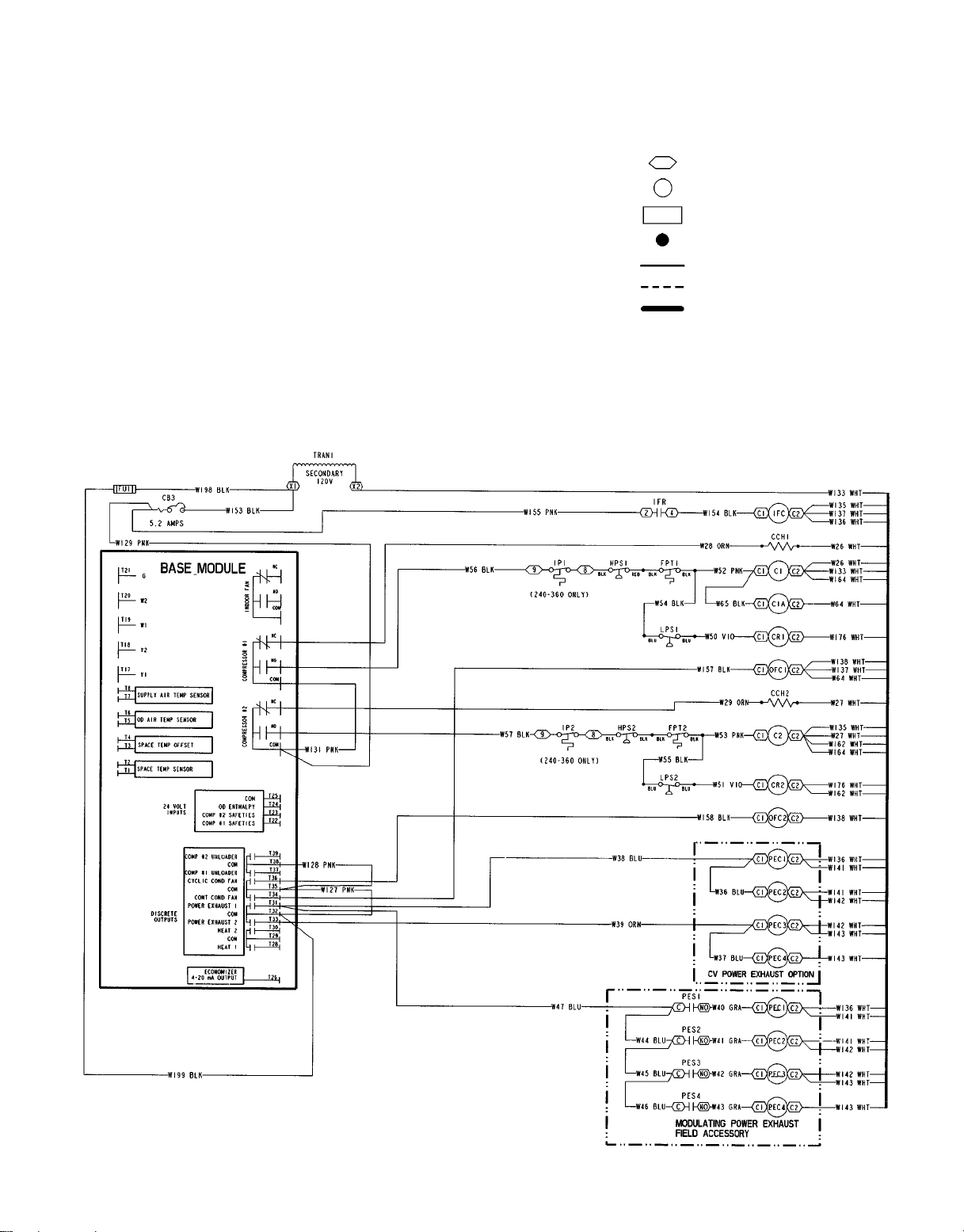
LEGEND FOR FIG. 46-50
AHA — Adjustable Heat Anticipator
BP — Building Pressure
BR — Burner Relay
C—Contactor, Compressor
CAP — Capacitor
CB — Circuit Breaker
CC — Cooling Compensator
CCB — Compressor Circuit Breaker
CCH — Crankcase Heater
COM — Common
COMP — Compressor Motor
CR — Control Relay
CV — Constant Volume
DM — Damper Motor
EC — Enthalpy Control
EQUIP — Equipment
FLA — Full Load Amps
FPT — Freeze Protection Thermostat
FU — Fuse
GND,GRD — Ground
GVR — Gas Valve Relay
HPS — High-Pressure Switch
HR — Heat Relay
HS — Hall Effect Sensor
HV — Heat Valve
I—Ignitor
IDM — Induced-Draft Motor
IFC — Indoor Fan Contactor
IFCB — Indoor Fan Circuit Breaker
IFM — Indoor-Fan Motor
IFR — Indoor-Fan Relay
IGC — Integrated Gas Unit Controller
IP — Internal Protector
L—Light
LPS — Low-Pressure Switch
LS — Limit Switch
MGV — Main Gas Valve
NC — Normally Closed
NEC — National Electrical Code
NO — Normally Open
OAT — Outdoor-Air Thermostat
OD — Outside Diameter
OFC — Outdoor-Fan Contactor
OFM — Outdoor-Fan Motor
PEC — Power Exhaust Contactor
PEM — Power Exhaust Motor
PES — Power Exhaust Sequencer
PESC — Power Exhaust Sequencer
PL — Plug Assembly
Controller
RS — Rollout Switch
SAT — Supply-Air Thermistor
SW — Switch
TB — Terminal Block
TC — Thermostat Cooling
TH — Thermostat Heating
TRAN — Transformer
Terminal (Marked)
Terminal (Unmarked)
Terminal Block
Splice
Factory Wiring
Field Wiring
To Indicate Common Potential Only,
Not To Represent Wiring
Fig. 46 — 115 V Control Circuit Schematic; 580G,H240-360
—37—
Page 38

NOTES:
1. Connect TRAN1 to H4 for 460 v units. Connect to H3 for 230 v. If
208/230 v units are run with a 208 v power supply connect to H2.
2. Connect TRAN2 to black lead for 460 v units. Connect to orange
lead for 230 v units. If 208/230 v units are run with a 208 v power
supply connect to red lead.
3. Circuit breaker must trip amps are equal to or less than 156% FLA
for CB1 and CB2. All others are 140%.
4. If any of the original wire furnished must be replaced, it must be
replaced with type 90 C wire or its equivalent.
5. Compressors and/or fan motors are thermally protected.
6. Three-phase motors are protected against primary single phasing
conditions.
Fig. 47 — Power Schematic; 580G,H240-360 — 208/230-3-60 and 460-3-60
—38—
TABLE A
The Following Compressors Have Two
Parallel Wires Run From TB1 to the
Compressor
Model
06D-537 208-230-3-60 2
The Following Fan Motors Have Two
Parallel Wires Run From TB1 to the Fan
Indoor
Motor
20 HP 208-230-3-60 2
Compressors
Voltage
TABLE B
Motors
Voltage
Wire
Quantity
Wire
Quantity
Page 39

NOTES:
1. Connect TRAN1 to H4 for 575V units.
2. Connect TRAN2 to black lead for 575V units.
3. Circuit breaker must trip amps are equal to or less than 156% FLA for CB1 and
CB2. All others are 140%.
4. If any of the original wire furnished must be replaced, it must be replaced with
Type 90 C wire or its equivalent.
5. Compressors and/or fan motors are thermally protected.
6. Three-phase motors are protected against primary single phasing conditions.
Fig. 48 — Power Schematic; 580G,H240-360 — 575-3-60
—39—
Page 40

—40—
NOTE: Red wire and violet wire are spliced together at the factory. The brown wire has a wire nut added at the factory.
Fig. 49 — 24 V Control Schematic; 580G,H240-360
Page 41

Fig. 50 — Component Arrangement; 580G,H240-360
—41—
Page 42

PACKAGED SERVICE TRAINING
Our packaged service training programs provide an excellent way to increase your knowledge of the
equipment discussed in this manual. Product programs cover:
• Unit Familiarization
• Installation Overview
• Maintenance
• Operating Sequence
A large selection of product, theory, and skills programs is available. All programs include a video
cassette and/or slides and a companion booklet. Use these for self teaching or to conduct full training
sessions.
For a free Service Training Material Catalog (STM), call 1-800-962-9212. Ordering instructions are
included.
Copyright 1997 Carrier Corporation CATALOG NO. 5358-000
Page 43

START-UP CHECKLIST
MODEL NO.:
SOFTWARE VERSION (SEE FIG. 11)
DATE:
PRE-START-UP:
M VERIFY THAT DIP SWITCH SETTINGS ARE CORRECT
M VERIFY THAT ALL PACKING MATERIALS HAVE BEEN REMOVED FROM UNIT
M REMOVE ALL SHIPPING HOLDDOWN BOLTS AND BRACKETS PER INSTRUCTIONS
M VERIFY INSTALLATION OF ECONOMIZER HOOD
M VERIFY INSTALLATION OF ALL OPTIONS AND ACCESSORIES
M VERIFY THAT CONDENSATE CONNECTION IS INSTALLED PER INSTRUCTIONS
M VERIFY THAT ALL ELECTRICAL CONNECTIONS AND TERMINALS ARE TIGHT
M CHECK GAS PIPING FOR LEAKS
M CHECK THAT INDOOR-AIR FILTERS ARE CLEAN AND IN PLACE
M VERIFY THAT UNIT IS LEVEL WITHIN TOLERANCES
M CHECK FAN WHEELS AND PROPELLERS FOR LOCATION IN HOUSING/ORIFICE, AND VERIFY SETSCREW
IS TIGHT
SERIAL NO.:
TECHNICIAN:
M VERIFY THAT FAN SHEAVESARE ALIGNED AND BELTS ARE PROPERLY TENSIONED
M VERIFY THAT SUCTION, DISCHARGE, AND LIQUID SERVICE VALVES ON EACH CIRCUIT ARE OPEN
START-UP:
ELECTRICAL
SUPPLY VOLTAGE L1-L2
COMPRESSOR AMPS — COMPRESSOR NO. 1 L1 L2 L3
— COMPRESSOR NO. 2 L1 L2 L3
SUPPLY FAN AMPS EXHAUST FAN AMPS
TEMPERATURES
OUTDOOR-AIR TEMPERATURE F DB (Dry Bulb)
RETURN-AIR TEMPERATURE
COOLING SUPPLYAIR
GAS HEAT SUPPLY AIR
PRESSURES
GAS INLET PRESSURE
GAS MANIFOLD PRESSURE STAGE NO. 1
L2-L3 L3-L1
FDB F WB (Wet Bulb)
F
F
IN. WG
IN. WG STAGE NO. 2 IN. WG
REFRIGERANT SUCTION CIRCUIT NO. 1
REFRIGERANT DISCHARGE CIRCUIT NO. 1
M VERIFY REFRIGERANT CHARGE USING CHARGING CHARTS ON PAGE 31
PSIG CIRCUIT NO. 2 PSIG
PSIG CIRCUIT NO. 2 PSIG
CL-1
Page 44

GENERAL
M SET ECONOMIZER MINIMUM VENT POSITION TO JOB REQUIREMENTS
M ENSURE DRIVES OPERATE WITHIN LIMITS OF FAN PERFORMANCE TABLES.
HIGH-PRESSURE SWITCH SETTING PSIG
LOW-PRESSURE SWITCH SETTING PSIG
MOTOR PULLEY PART NUMBER
FAN PULLEY PART NUMBER
BELT PART NUMBER
BELT SIZE in.
FILTER QUANTITY
FILTER SIZES in.
ADDITIONAL NOTES:
Copyright 1997 Carrier Corporation CATALOG NO. 5358-000
CUT ALONG DOTTED LINE CUT ALONG DOTTED LINE
----------------------------------------------------------------------------------------
 Loading...