

Page 1
39006DP8-A 5/15/80
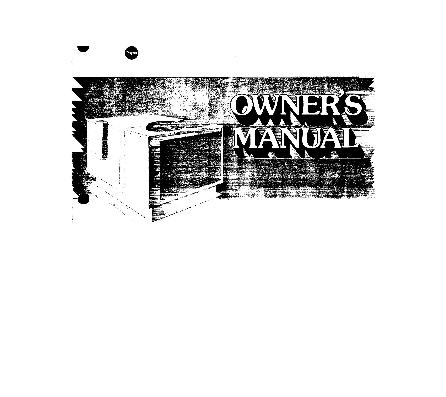
Commercial Outdoor
Combination Gas Heating/
Electric Cooling Units
FOR YOUR SAFETY
If you smell gas:
1. Open windows.
2. Don’t touch electrical switches.
3. Extinguish any open flame.
4. Immediately call your gas supplier.
FOR YOUR SAFETY
Do not store or use gasoline or other
flammable vapors and liquids in the
vicinity of this or any other appliance.
OPERATION
MAINTENANCE
SERVICE
Congratulations on your wise investment in a
modern, quality, Model 579C Combination Gas Heating/
Electric Cooling Unit. Your heating/cooling unit has been
designed and developed to provide safe, reliable, and
economic operation when properly installed and maintained.
Your year-round air conditioner is a major investment;
therefore, you will expect it to perform at its best. By reading
this manual, you can learn how to operate it, do recom
mended routine maintenance, and what to do if a problem
should arise. Your new unit should perform at the efficiency
level built into it if you will contribute a little of your time
and attention.
NOTE TO INSTALLER: This manual should be left with equipment owner=
Page 2
Special Instructions to Equipment Owner
NOTE: Retain this manual for future reference.
Your heating/cooling unit must have a supply of fresh
outdoor air circulating around it during both heating and
cooling operation. When the gas heating section is operating,
the unit needs fresh air for proper gas combustion and
proper ventilation. When the cooling section is operating, the
unit needs fresh air for proper airflow through the outdoor
(condenser) coil.
_ygfflNG: Improper installation, adjustment, al-
rajibh, service, maintenance, or use can cause carbon
_ îdè poisoning, explosion, fire, electric shock, or
j^Kher occurrences which may injure you or damage
3Wpfty. Consult a qualified installer, service
“of the gas supplier for information or
Your Comfort System
Your efficient new gas/electric unit not only represents the
very latest in modern engineering development and design
— it is a result of over 70 years of experience in gas-fired
heating systems.
^^^TSjRNINGT'To minimize the possibility of serious
*;»*. personal injury, fire, dam^e to your heating/cooling
unit, or improper unit operation, never violate the
jjaLlfoUowing safety rules:
wavs keep the aresT around your unit free oï
mstiMeJn_aterials, gasoline, and other flam-
jgjiguids and vapors,
Mvéf your^hit, lean anything against it,
Ifash or debris near it, stand on it, or in any
vray block How of fresh outdoor air to your
unit.
ST^eyeF plant trees, lErubbery, or Bowers near
■ycmr unit; and be sure to prevent weeds and/or
pthir^yegetation from growing up around your
^ j-ggg recommended operational and service
Heating/Cooling Unit Identification
MODEL NO.
PRODUCT NO.
SERIAL NO. _
____________________
________________________
In the unit Installation Instructions.)
For your convenience, you or your installer should, or should
have, recorded (printed) the following information that is
applicable to your system:
Operating Your Heating/Cooling Unit
The key to operating your comfort system is the conditioned
space thermostat. A wide variety of thermostats is used, but
all have one main function — to automatically maintain the
temperature in your building at a level required for your
personal comfort, or for a particular application e.g.
computer rooms. The thermostat maintains the indoor
temperature by controlling the operation of the unit. During
the heating season, whenever the temperature around your
thermostat drops below the thermostat temperature setting,
the thermostat automatically starts the heating section.
During the cooling season, whenever the temperature
around your thermostat rises above the thermostat tempera
ture setting, the thermostat automatically starts the cooling
section.
Your conditioned space thermostat has a temperature
control selector for selecting the desired indoor temperature.
It also has a FAN switch with two selections available:
AUTO or ON. When set to AUTO, the blower will operate
only when the thermostat starts the unit. When set to ON, the
DATE INSTALLED
Dealer
NAME
ADDRESS
CITY
STATE .
PHONE
blower will run continuously, regardless of whether the
heating or cooling section is operating.
The SYSTEM switch on your thermostat has the following
selections: HEAT, OFF, and COOL. Some thermostats may
also have a fourth selection — AUTO. The unit will remain
off regardless of the conditioned space temperature when the
SYSTEM switch is set to the OFF position. When set to the
HEAT position, the heating section will operate as required.
With the SYSTEM switch set to the COOL position, the cool
ing section will operate as required.
The SYSTEM switch AUTO selection on some thermostats
provides for automatic changeover between heating and
cooling operation. With the switch set in AUTO position, the
heating section will operate when the conditioned space
temperature drops below the thermostat heating
temperature setting, or the cooling section will operate when
the conditioned space temperature rises above the
thermostat cooling temperature setting.
___________
_____
ZIP.
Page 3
Gas Heating Section Startup and Shutdown
The gas heating section of your combination heating/cooling
unit is equipped with automatic intermittent ignition
devices that do not have continuously burning pilot flames.
The pilots are automatically lit by electric sparking devices
each time your conditioned space thermostat “calls for heat.”
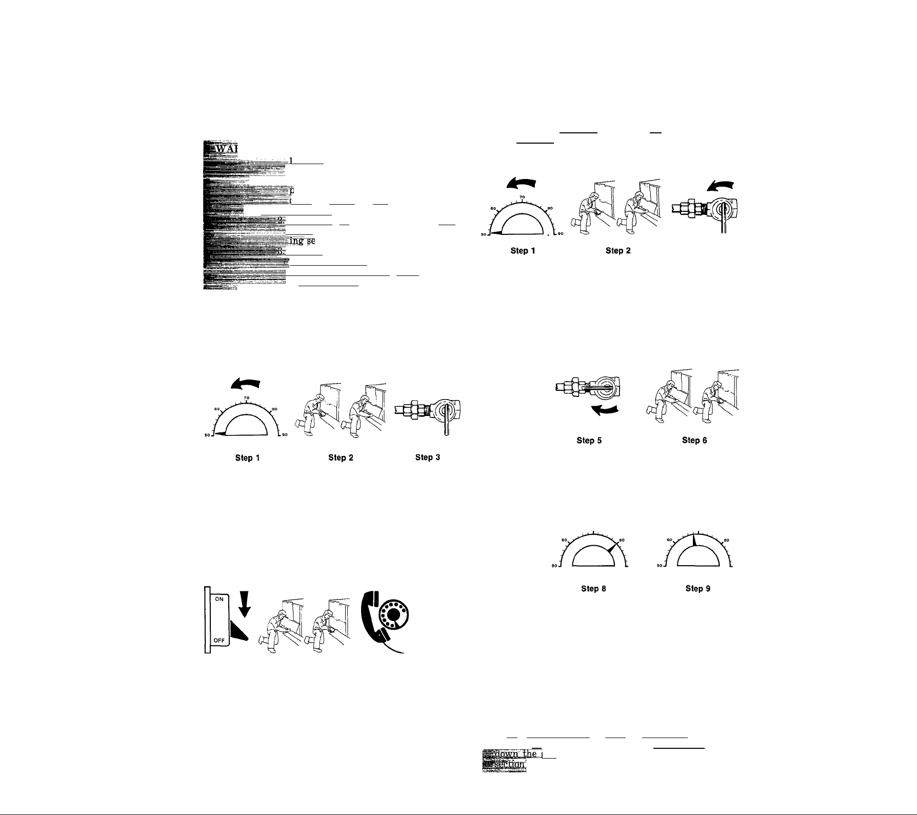
See Figure 3.
fflIPiG: i. liever attempt to manually light the
^^^Mflealei^-far-seEvice.
qilots on this unit with a match or any
ather open flame. If the electric
^sparking devices fail to light the
=^Fq1Iow the instructions on the unit :
bating plate when starting the heat_
ilfja_suspected malfunction occurs,
PSfeT^hrthe following shutdown proEgBduEe, then caH your dealer for ’
i^ervic~rhrs~s~cr(nras possibleT
refer to the following shut-
|pwn_ procedures, and calf your
..............
stion. See Figure 1. '
Shutting Down Your Gas Heating Section step 2-
You may be required to, or want to, turn off your gas heating
section for one of two reasons: a suspected malfunction has
occurred, or the heating season has ended.
Starting Your Gas Heating Section
NOTE: Be sure air filters are clean and in place. (See
Figure 2 and maintenance section of this manual.)
before attempting to start the gas
agrsfiCtionTiamnianze yourself with all the pro-
it mq^t be followed.
Step 3
Proceed as follows to start your gas heating section:
Step 1— Set your conditioned space thermostat to the lowest
Step 3-
temperature setting and set SYSTEM switch to
HEAT.
Remove lower heating section access panel. See
Figure 1.
Turn manual gas shutoff to OFF position and wait
5 minutes. See Figure 3.
Proceed as follows to shut down the gas heating section:
Step 1— Set your conditioned space thermostat to the lowest
temperature setting and set SYSTEM switch to
OFF.
Step 2— Remove lower heating section access panel to your
unit. See Figure 1.
Step3— Turn manual gas shutoff to OFF position by
placing shut-off lever at right angle to gas line. See
Figure 3.
Step 4 Step 5 Step 6 Step 7
Step 4— Turn OFF the electrical power to your unit.
Step 5— Replace lower heating section access panel.
Step 6— If the unit is being shut down because of a mal
function, call your dealer for service as soon as
possible.
Step 7— If your unit is being shut down because the heating
season has ended, restore electrical power to the
unit to ensure operation of the cooling system
during the cooling season.
I
K
step 4
Step 4— Turn OFF the electrical supply to your unit.
Step 5— After waiting 5 minutes, turn the manual gas shut
Step 6— Replace the lower heating section access panel.
Step 7— Turn ON the electrical supply to your unit.
Step 8— Set the conditioned space thermostat slightly above
Step 9— Set the temperature selector on your conditioned
off to the ON position.
1
Step 7
the space temperature to start your unit. The pilot
ignition systems now begin sparking and light the
pilots. After a 40- to 70-second time-delay, the
secondary gas valve and main gas valve-regulator
open. Gas now flows to the burners at a regulated
rate and the ignited pilots light the burners. After
approximately 2 minutes, the blower motor starts.
space thermostat to the desired temperature
setting.
__ TNG: ^Г The plots faiFto ignite, the main
meStiirto light, or the blower failsTb come on. shut
yas heating section ]seeTMbbedure_in this
tMd call your dealer for gerviee.
....................
.
Page 4
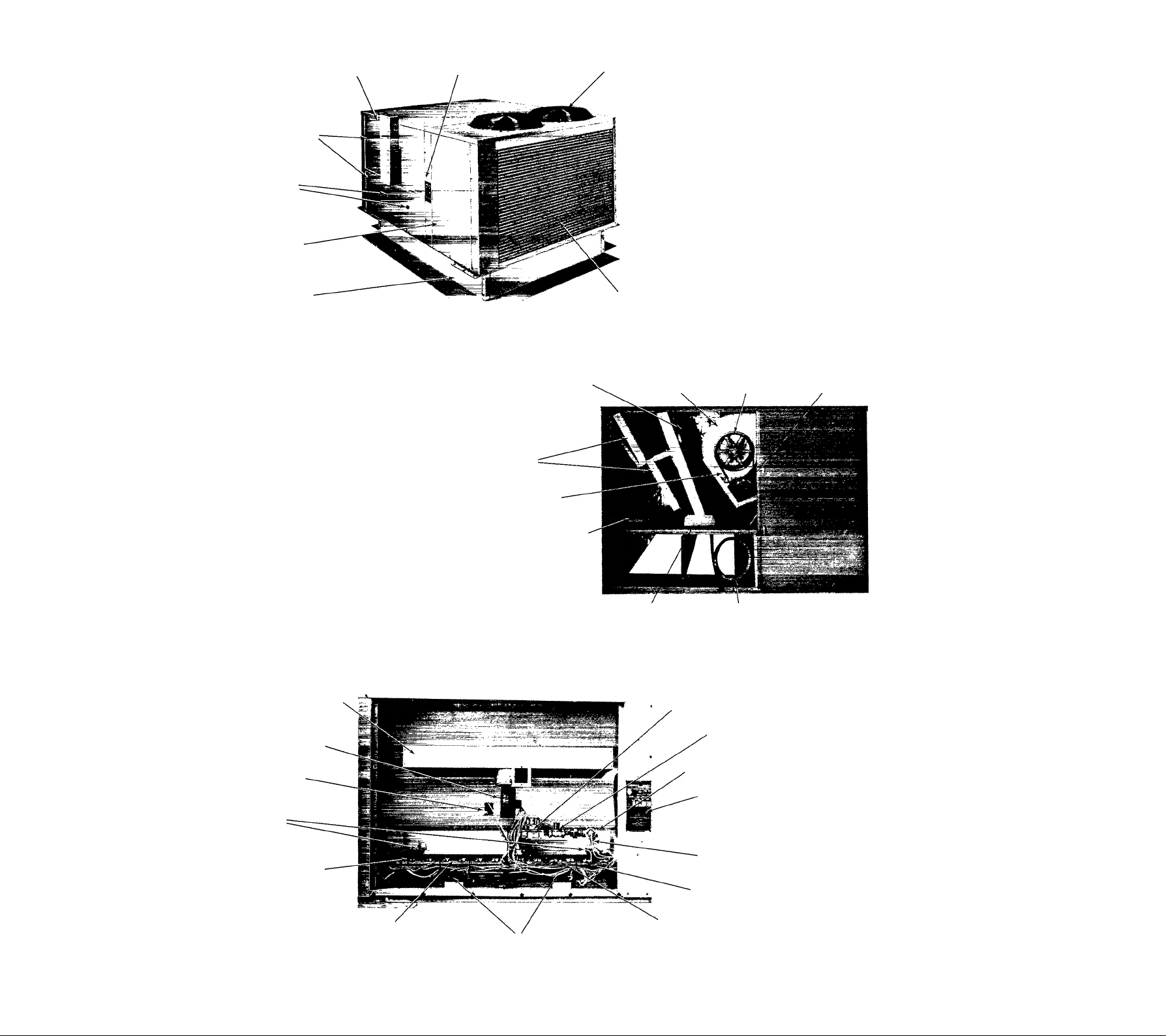
Flue Vent
(Hot During Heating)
Heating Section
Access Paneis
Burner
Observation
Ports
Control and
Compressor
Access Panel
Unit Rating
Piate
Condenser Fan Guard
(Two on this Unit)
Optional Roof
Mounting Curb
Figure 1 — Model 579C
Evaporator
Coil
Filters
Drive Beit
Air Filters and
Lubrication
Labei
Figure 2 — Blower & Filter Access Panel Removed
Condenser Coil
(One on this Unit)
Blower
Housing
Drain
Pan
Condensate
Drain Tube
Blower
Pulley
Blower
Motor
Flue Collector Box
Combustion-Air
Blower Motor
Limit Switch
Flame
Roll-Out
Limits
Gas Burner
(12 on this Unit)
Figure 3 — Heating Section Access Panels Removed
Electric Spark-
Ignition Pilot
(High-Voltage)
Spark Generators
(High-Voltage)
4
Combination Gas
Valve-Regulator
Secondary
Gas Valve
Gas Inlet Hole
Rating Plate
(Includes
Operating
instructions)
Manual Gas
Shutoff
Gas Manifold
Electric Spark-
Ignition Pilot
(High-Voltage)
Page 5

Maintenance by Qualified Service Personnel
Your heating/cooling unit should be inspected by a trained
and equipped service person at least once each year. During
this inspection, the qualified service person should perform
the following minimum maintenance:
1. Inspect all flue product passages, the flue venting sys
tem, the pilots, and the burners.
2. Inspect all combustion and ventilation air passages and
openings.
3. Check gas pipes leading to and inside your unit for
leaks.
4. Readjust the gas/air mixture if the burner flames are
not bright blue.
5. Check, and when necessary, clean the condenser and
evaporator coils.
Maintenance and Care for the Equipment Owner
Before proceeding with those things you may w;ant to main
tain yourself, please carefully consider the following:
.^WARNING: 1. TURN OFF GAS SUPPLY AND
ELECTRICAL POWER TO YOUR
“ UNIT BEFORE SERVICING OR
PERFORMING MAINTENANCE.
T' 2. When removing access doors or per
forming maintenance functions in
side your unit, be aware of sharp
_ sheet metal parts and screws. Al
though special care has been taken to
reduce sharp edges to a minimum, be
extremely careful when handling
parts or reaching into the unit.
Check, and when necessary, clean the evaporator drain
pan and drain lines.
Inspect and clean the blower wheel and housing. Also,
lubricate the blower motor as required.
Inspect and change air filters if necessary.
Inspect all supply- and return-air ducts for obstruc
tions, air leaks, and insulation. Remedy any problem
when necessary.
Inspect electrical wiring and components for loose
10.
connections.
Check all safety devices for proper operation.
11.
Perform an operational checkout to determine whether
12.
the unit is working properly, and if it requires
adjustments.
Lubrication
The combustion-air blower motor and condenser fan motors
are prelubricated and do not require lubrication.
If the indoor-air blower motor is equipped with oil cups, oil
motor bearings with SAE10-20 nondetergent oil at begin
ning of each heating and cooling season. Use approximately
six drops for each bearing.
Some blower motors are equipped with bearings of a pre
lubricated type.
Blower bearings are the prelubricated type.
Evaporator and Condenser Coils.
Air Filters
Air filters should be checked every 3 or 4 weeks and changed
when they become dirty.
The size and number of filters varies. Always use the same
size and type of filters that were originally supplied. See
“Filter Table.” Make sure that arrows on edge of filter point
in direction of airflow (toward blower).
FILTER TABLE
Model
579C090250
579C120300
579C150300
579C180400 (2) 16 x 20 x 2, (4) 16 x 25 x 2 Disposable
579C240450 (6) 20 x 20 x 2, (2) 20 x 25 x 2 Disposable
579C300600 (6) 25 X 25 X 2, (2) 20 x 25 x 2 Disposable
579C360600
Filter (No. & Size)
(4) 16 X 25 X 2 Disposable
Filter Type
Heat Exchanger
This checkout should not be attempted by anyone not having
the required expertise and equipment to do the job properly.
Checking and/or cleaning the heat exchanger involves re
moving the flue collector box and fuel baffles. Contact your
dealer for the required periodic maintenance.
Evaporator coils should be cleaned by a qualified service
person only.
Condenser coil(s) can be cleaned with a garden hose by
spraying the coil with water from the inside of the unit
toward the outside.
iWARNING: Extreme caution must be used wLra
iispraying the coil, to avoid getting water in the com-
pressSrterminal box or unit control box. It may be de-
le to cover these with plastic before spraying.
Condensate Drain
The drain pan and condensate drain line should be checked
and cleaned at the same time the cooling coils are checked by
your dealer.
Condenser Fans
SWARNING: Do not poke sticks, screwdrivers, or any
objects into the revolving fan blades
ilv“'
iüryrnâv "result
The fan must be kept free of all obstructions to ensure proper
cooling. Contact your dealer for any required service.
severe
Electrical Controls and Wiring
Electrical controls are difficult to check without proper in
strumentation; therefore; if there are any discrepancies in
the operating cycle, contact your dealer for service.
Page 6
Refrigerant Circuit
The refrigerant circuit is difficult to check for leaks without
proper equipment: therefore, if inadequate cooling is sus
pected, contact your local dealer for service.
Combustion Area and Vent System
The combustion area and vent system should be visually in
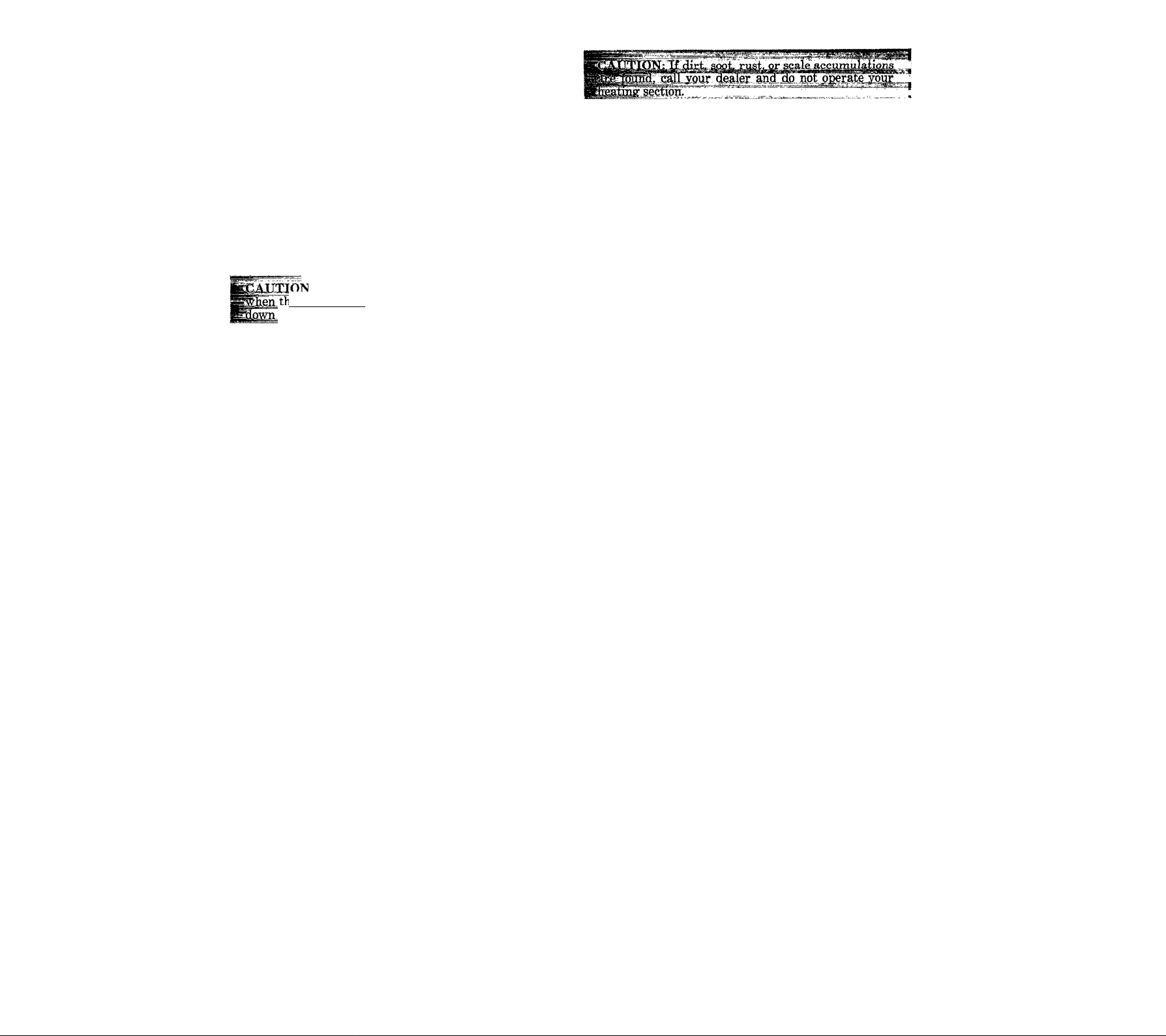
spected before each heating season. The normal accumula
tion of dirt, soot, rust, or scale can result in loss of efficiency
and improper performance if allowed to build up. Accumu
lation on the main burners can result in the burners firing
out of normal time sequence. This delayed ignition is charac
terized by an extra loud Ignition that can be quite alarming.
; If your unit makes an especially loud noise
le main burners are ignited by the pilots, shut
the heatingsection and call your dealer.
Refer to Figures 1 and 3. Using a flashlight, proceed as
follows to inspect the combustion area and vent system of
your unit.
1. Turn off gas supply and electrical power to your unit.
2. Remove heating section access panels.
3. Carefully inspect gas burners and pilot areas for dirt,
soot, rust, or scale.
Before Calling for Service
4. When you have completed your inspection, follow the
startup procedures in this manual to restore your unit to
operation.
5. Replace heating section access panels.
6. Observe unit heating operation, and watch the burner
flames through the observation ports (see Figure 1) to see
if they are bright blue. If you observe a suspected mal
function, or that the burner flames are not bright blue,
call your dealer.
NOTE: Burner flames that have a mixture of yellow,
orange, or red flames together with the blue may
not be burning gas efficiently. Your dealer may
have to adjust the air/gas mixture and/or clean the
burners.
If your combination gas heating/electric cooling unit does
not appear to be performing properly, or does not operate at
all, you may save the cost of an unscheduled service call if you
check a few things yourself before calling for service.
Insufficient Airflow
After your equipment has been in operation for a short
period, you should become familiar with the “feel” of the air
circulation. If you sense a change in the airflow, your
problem is probably dirty air filters. Inspect the filters.
If you determine that dirty filters are not causing the
problem, call your dealer for service.
Unit Fails to Operate
Sometimes a unit will stop operating because of an actual
malfunction: however, it is common for a unit to appear to
have stopped operating because an easily remedied situation
has taken place. If your unit fails to operate, follow these
step-by-step procedures, and proceed only to the next step if
the unit fails to start.
1. Check to be sure that the conditioned space thermostat
is above the space temperature during heating season, or
below the space temperature during the cooling season.
Also, make sure that SYSTEM switch is in the proper
HEAT or COOL position — and not in the OFF position.
2. Check to be sure that the electrical power supply to your
unit is ON, that a fuse has not blown, or that a circuit
breaker has not tripped.
3. During the heating season, check to be sure that the
manual shut-off valve in the gas supply pipe leading to
your unit is in the open position. The valve is open if the
lever points in the same direction the pipe runs, and it is
closed if the lever is at a right angle to the pipe. If the
valve is closed, open it and then follow the startup pro
cedures in this manual..
4. During the heating season, check the manual gas shutoff
to be sure that it is in the ON position.
5. If your unit still fails to operate, call your dealer for
service.
When Calling for Service
The product, model, and serial numbers for your unit, to
gether with the date installed (recorded in the space pro
vided at the front of this manual), will be helpful for your
dealer. If the dealer knows exactly what you have, he may be
able to offer some suggestions over the phone to remedy the
problem. This could save you needless expense and the dealer
a needless visit.
NOTE: If you do not have a dealer, refer to your telephone
directory or yellow pages for the nearest dealer for
the brand name of your unit.
COPYRIGHT ® 1980
BDP Company
Division of Carrier Corp.
 Loading...