

Page 1
©Copyright 2010 BROT
HER INDUSTRIES, LTD.
Version 1.20
Model Name Specifications
ESC/P commands
Study: TD-4000/4100N
<Written By> Brother Industries, Ltd.
1
Page 2
Machine Model: TD-4000/TD-4100N
IMPORTANT - PLEASE READ CAREFULLY
This documentation (“Documentation”) gives you information that will assist you in controlling
your Machine Model.
You may use the Documentation only if you first agree to the following conditions.
If you do not agree to the following conditions, you may not use the Documentation.
Condition of Use
You may use and reproduce the Documentation to the extent necessary for your own use of
your Machine Model (“Purpose”). Unless expressly permitted in the Documentation, you may
not;
(i) copy or reproduce the Documentation for any purpose other than the Purpose,
(ii) modify, translate or adapt the Documentation, and/or redistribution to any third party,
(iii) rent or lease the Documentation to any third party, or,
(iv) remove or alter any copyright notices or proprietary rights legends included within
the Documentation.
No Warranty
a. Any updates, upgrades or alteration of the Documentation or Machine Model will be
performed at the sole discretion of Brother. Brother may not respond to any request or
inquiry about the Documentation.
b. THIS DOCUMENTATION IS PROVIDED TO YOU "AS IS" WITHOUT WARRANTY OF ANY
KIND, WHETHER EXPRESS OR IMPLIED, INCLUDING, BUT NOT LIMITED TO, THE
IMPLIED WARRANTY OF FITNESS FOR A PARTICULAR PURPOSE. BROTHER DOES
NOT REPRESENT OR WARRANT THAT THIS DOCUMENTATION IS FREE FROM
ERRORS OR DEFECTS.
c. IN NO EVENT SHALL BROTHER BE LIABLE FOR ANY DIRECT, INDIRECT, PUNITIVE,
INCIDENTAL, SPECIAL, CONSEQUENTIAL DAMAGES OR ANY DAMAGES
WHATSOEVER, ARISING OUT OF THE USE, INABILITY TO USE, OR THE RESULTS OF
USE OF THE DOCUMENTATION OR ANY SOFTWARE PROGRAM OR APPLICATION
YOU DEVELOPED IN ACCORDANCE WITH THE DOCUMENTATION.
2
Page 3

[Contents]
Control Code List ................................................................................................................7
Print area...........................................................................................................................10
Characters ......................................................................................................................... 12
Print position.....................................................................................................................15
Line feed amount...............................................................................................................17
Document creation flow ....................................................................................................18
Control command details ..................................................................................................20
・ .......................................................................20 Character/style selection commands
ESC R Select international character set ..........................................................20
ESC q Select character style ..............................................................................21
ESC k Select font ................................................................................................22
ESC t Select character code table ......................................................................22
・ ...........................................................................................23 Text printing commands
ESC 4 Apply italic style......................................................................................23
ESC 5 Cancel italic style ....................................................................................23
ESC E Apply bold style.......................................................................................24
ESC F Cancel bold style .....................................................................................24
ESC G Apply double-strike printing ..................................................................25
ESC H Cancel double-strike printing ................................................................25
ESC P Specify pica pitch.....................................................................................26
ESC M Specify elite pitch ...................................................................................27
ESC g Specify micron pitch ................................................................................28
ESC p Specify proportional characters ..............................................................29
ESC W Specify double width characters............................................................ 30
SO Specify auto-cancelling enlarged characters................................................31
ESC SO Specify auto-cancelling enlarged characters .......................................31
SI Specify reduced characters ............................................................................32
ESC SI Specify reduced characters.................................................................... 32
DC2 Cancel reduced characters .........................................................................32
DC 4 Cancel auto-cancelling double-width characters......................................33
ESC – Applies/cancels underlining ....................................................................34
ESC ! Global formatting .....................................................................................36
ESC SP Specify character spacing .....................................................................37
ESC X Specify character size..............................................................................38
3
Page 4

・ ................................................................................................39 Line feed commands
ESC 0 Specify line feed of 1/8 inch..................................................................... 39
ESC 2 Specify line feed of 1/6 inch..................................................................... 39
ESC 3 Specify minimum line feed......................................................................39
ESC A Specify line feed of n/60 inch................................................................... 40
・ ..............................................................41 Horizontal direction movement commands
ESC l Specify left margin ...................................................................................41
ESC Q Specify right margin...............................................................................44
CR Carriage return............................................................................................. 46
ESC D Specify horizontal tab position............................................................... 47
HT Apply horizontal tab.....................................................................................48
ESC $ Specify absolute horizontal position .......................................................49
ESC \ Specify relative horizontal position ........................................................49
ESC a Specify alignment ....................................................................................50
・ .................................................................................51 Vertical movement commands
LF Line feed ........................................................................................................ 51
FF Page feed........................................................................................................ 51
ESC J Forward paper feed .................................................................................52
ESC B Specify vertical tab position ...................................................................53
VT Apply vertical tab..........................................................................................54
ESC (V Specify absolute vertical position.......................................................... 55
ESC (v Specify relative vertical position............................................................56
・ ......................................................................................................57 Paper formatting
ESC (c Specify page format ................................................................................57
ESC (C Specify page length................................................................................ 58
・ ........................................................................................59 Printer control commands
ESC @ Initialize .................................................................................................. 59
・ ................................................................................................60 Graphics commands
ESC * Select bit image........................................................................................60
ESC K 8-dot standard-density bit image ...........................................................65
ESC L 8-dot double-density bit image................................................................67
ESC Y 8-dot double-speed double-density bit image.........................................68
ESC Z 8-dot quadruple-density bit image.......................................................... 68
・ ...............................................................................................69 Advanced commands
ESC i B Bar code................................................................................................. 69
ESC i Q 2D Bar code QR codes........................................................................... 73
ESC i P QR code version setting ........................................................................76
4
Page 5

ESC i V 2D bar code PDF417 .............................................................................77
ESC i D 2D bar code DataMatrix control...........................................................80
ESC i M 2D bar code MaxiCode control............................................................. 83
ESC i F Print downloaded data..........................................................................85
ESC i a Switch command mode.......................................................................... 89
ESC i S Request printer status .......................................................................... 90
ESC i L Select landscape orientation.................................................................92
ESC i C Specify cutting.......................................................................................93
ESC iXQ2 Select default character style ...........................................................94
ESC iXQ1 Retrieve default character style ....................................................... 95
ESC iXk2 Select default font..............................................................................96
ESC iXk1 Retrieve default font..........................................................................97
ESC iXX2 Specify default character size ........................................................... 98
ESC iXX1 Retrieve default character size .........................................................99
ESC iX32 Specify default line feed................................................................... 100
ESC iX31 Retrieve default line feed.................................................................101
ESC iXA2 Select default alignment .................................................................102
ESC iXA1 Retrieve default alignment .............................................................103
ESC iX(2 Specify default page length ..............................................................104
ESC iX(1 Retrieve default page length ............................................................ 105
ESC iXL2 Select default landscape orientation...............................................106
ESC iXL1 Retrieve default landscape orientation...........................................107
ESC iXj2 Select default international
ESC iXj1 Retrieve default international character set ................................... 109
ESC iXm2 Select default character code table ................................................110
ESC iXm1 Retrieve default character code table ............................................ 111
・ ..................................................................................................... 112 Character codes
Standard character code table
Eastern European character code table (W
Western European character code table (W
International character set............................................................................... 115
character set .......................................108
for ESC/P codes............................................... 112
indows-1250) ............................... 113
indows 1252) ............................... 114
5
Page 6

Introduction
This material provides the necessary information for directly controlling TD-4000/4100N.
This information is provided assuming that the user has full understanding of the operating
system being used and basic mastery of RS-232C, USB or Ethernet in a developer's
environment.
We accept no responsibility for any problems caused by programs that you develop using
the information provided in this material, affecting software, data or hardware, including the
TD-4000/4100N, and any problems resulting directly or indirectly from them. Use this
material only if you accept these terms.
This material shall not be reproduced, in part or in full, without prior approval. In addition,
this material shall not be used as evidence in a lawsuit or dispute in a way that is
unfavorable towards our company.
These ESC/P
commands have been adapted specifically for this company.
6
Page 7
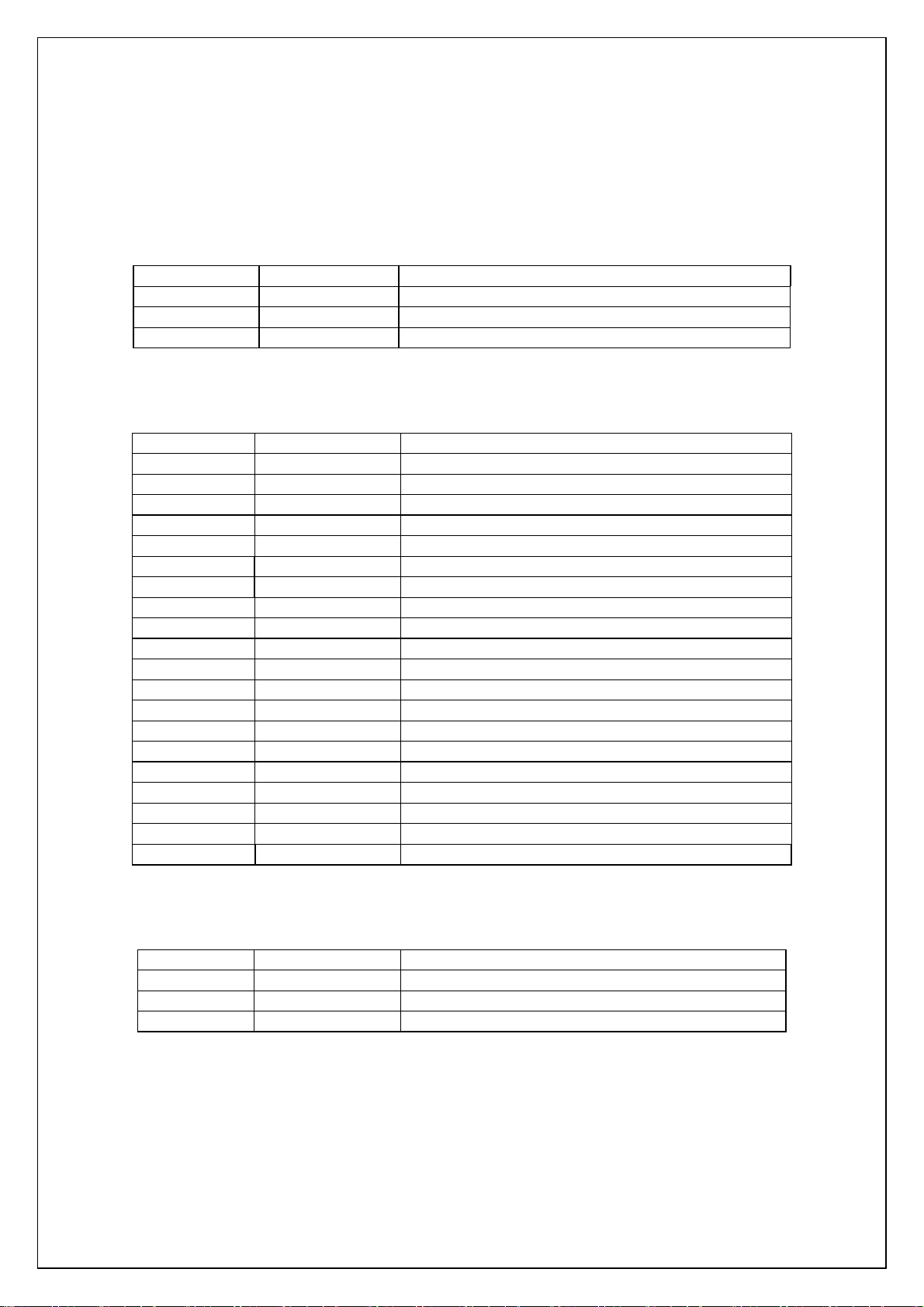
Control Code List
Character/style selection
ESC R 1B 52 Select international character set
ESC q 1B 71 Select character style
ESC k 1B 6B Select font
ESC t 1B 74 Select character code table
Text printing
ESC 4 1B 34 Apply italic style
ESC 5 1B 35 Cancel italic style
ESC E 1B 45 Apply bold style
ESC F 1B 46 Cancel bold style
ESC G 1B 47 Apply double-strike printing
ESC H 1B 48 Cancel double-strike
ESC P 1B 50 Specify pica pitch (10 cpi)
ESC M 1B 4D Specify elite pitch (12 cpi)
ESC g 1B 67 Specify micron pitch
ESC p 1B 70 Specify proportional characters
ESC W 1B 57 Specify double-width characters
SO 0E Specify auto-cancelling enlarged characters
ESC SO 1B 0E Specify auto-cancelling enlarged characters
SI 0F Specify reduced characters
ESC SI 1B 0F Specify reduced characters
DC2 12 Cancel reduced characters
DC4 14 Cancel auto-cancelling double-width characters
ESC - 1B 2D Apply/cancel underlining
ESC ! 1B 21 Global formatting
ESC SP 1B 20 Specify character spacing
ESC X 1B 58 Specify character size
Line feeds
ESC 0 1B 30 Specify line feed of 1/8 inch
ESC 2 1B 32 Specify line feed of 1/6 inch
ESC 3 1B 33 Specify minimum line feed.
ESC A 1B 41 Specify line feed of n/60 inch
7
Page 8
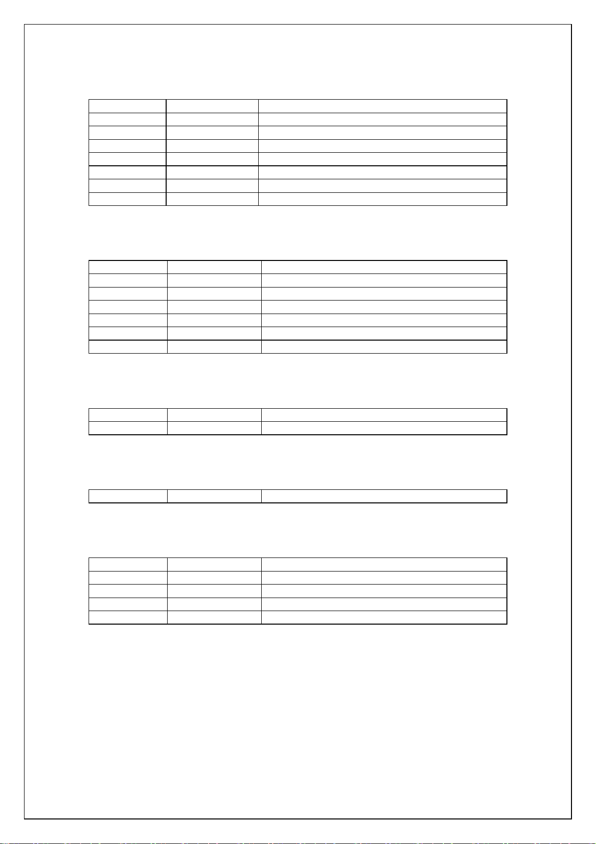
Horizont
ESC l 1B 6C Specify left margin.
ESC Q 1B 51 Specify right margin.
CR 0D Carriage return
ESC D 1B 44 Specify horizontal tab position
HT 09 Apply horizontal tab
ESC $ 1B 24 Specify absolute horizontal position
ESC \ 1B 5C Specify relative horizontal position
ESC a 1B 61 Specify alignment
Vertical movement
LF 0A Line feed
FF 0C Page feed
ESC J 1B 4A Forward paper feed
ESC B 1B 42 Specify vertical tab position
VT 0B Apply vertical tab
ESC ( V 1B 28 56 Specify absolute vertical position.
ESC ( v 1B 28 76 Specify relative vertical position.
al direction movement
Paper formatting
ESC ( c 1B 28 63 Specify page format.
ESC ( C 1B 28 43 Specify page length
Printer control
ESC @ 1B 40 Defaults
Graphic commands
ESC * 1B 2A Select a bit image.
ESC K 1B 4B 8-dot single-density bit image
ESC L 1B 4C 8-dot double-density bit image
ESC Y 1B 59 8-dot double-speed double-density bit image
ESC Z 1B 5A 8-dot quadruple-density bit image
8
Page 9
Advanced co
ESC i B 1B 69 42 Bar code
ESC i Q 1B 69 51 2D bar code QR codes
ESC i P 1B 69 50 QR code version setting
ESC i V 1B 69 56 2D bar codes PDF417
ESC i D 1B 69 44 2D bar code data matrix
ESC i M 1B 69 4D 2D bar code MaxiCode
ESC i F 1B 69 46 Print downloaded data
ESC i a 1B 69 61 Switch command mode
ESC i S 1B 69 53 Request printer status
ESC i L 1B 69 4C Select landscape orientation
ESC i C 1B 69 43 Specify cutting
Advanced static commands
ESC iXQ2 1B 69 58 51 32 Select default character style
ESC iXQ1 1B 69 58 51 31 Retrieve default character style
ESC iXk2 1B 69 58 6B 32 Select default font
ESC iXk1 1B 69 58 6B 31 Retrieve default font
ESC iXX2 1B 69 58 58 32 Specify default character size
ESC iXX1 1B 69 58 58 31 Retrieve default character size
ESC iX32 1B 69 58 33 32 Specify default line feed
ESC iX31 1B 69 58 33 31 Retrieve default line feed
ESC iXA2 1B 69 58 41 32 Select default alignment
ESC iXA1 1B 69 58 41 31 Retrieve default alignment
ESC iX(2 1B 69 58 28 32 Specify default page length
ESC iX(1 1B 69 58 28 31 Retrieve default page length
ESC iXL2 1B 69 58 4C 32 Select default landscape orientation
ESC iXL1 1B 69 58 4C 31 Retrieve default landscape orientation
ESC iXj2 1B 69 58 6A 32 Select default international character set
ESC iXj1 1B 69 58 6A 31 Retrieve default international character set
ESC iXm2 1B 69 58 6D 32 Select default character code table
ESC iXm1 1B 69 58 6D 31 Retrieve default character code table
mmands
9
Page 10
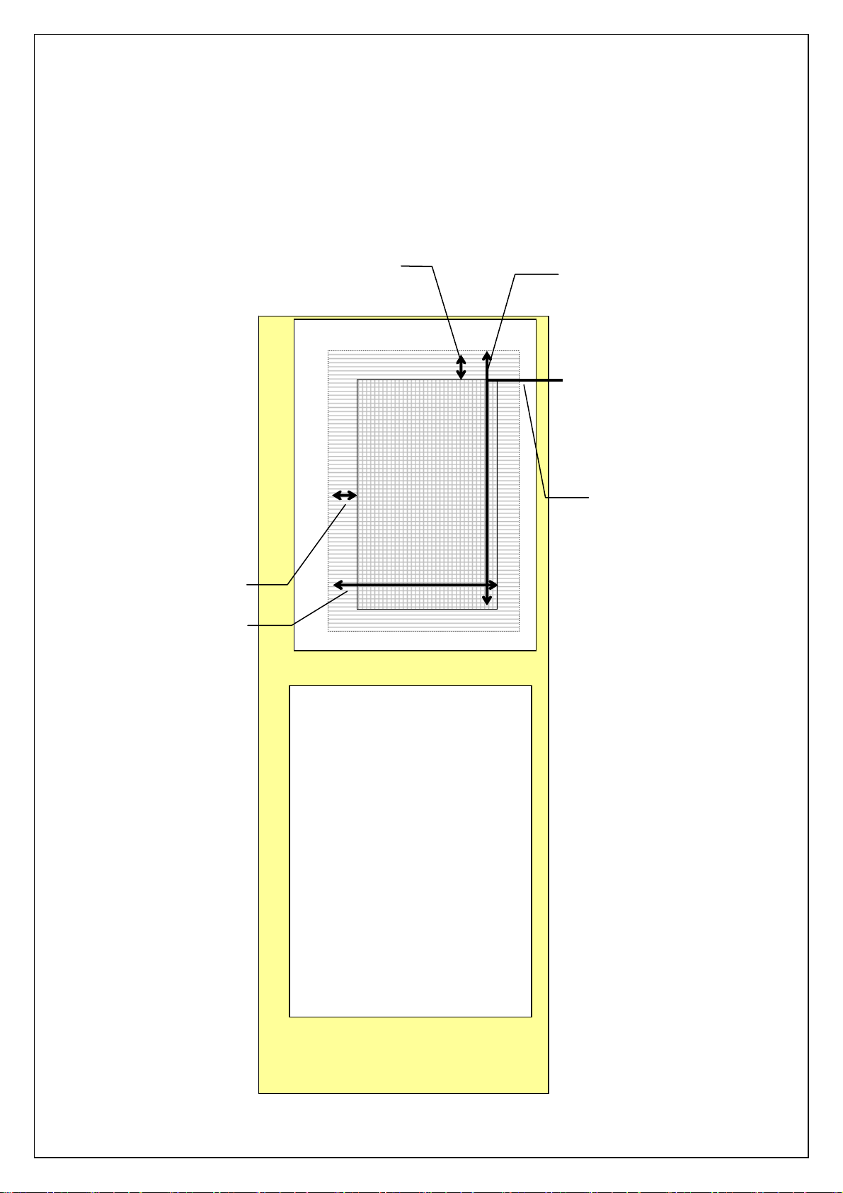
Print area
The printing media are die-cut labels and continuous length label.
The area that can physically be printed on depends on the size and type of the print media.
<<Die-cut>>
Left margin
Right margin
Top margin
Unprintable area
nted area
Unpri
Print area
Bottom margin
Top margin position
(TOF position)
Unprintable area
10
Page 11
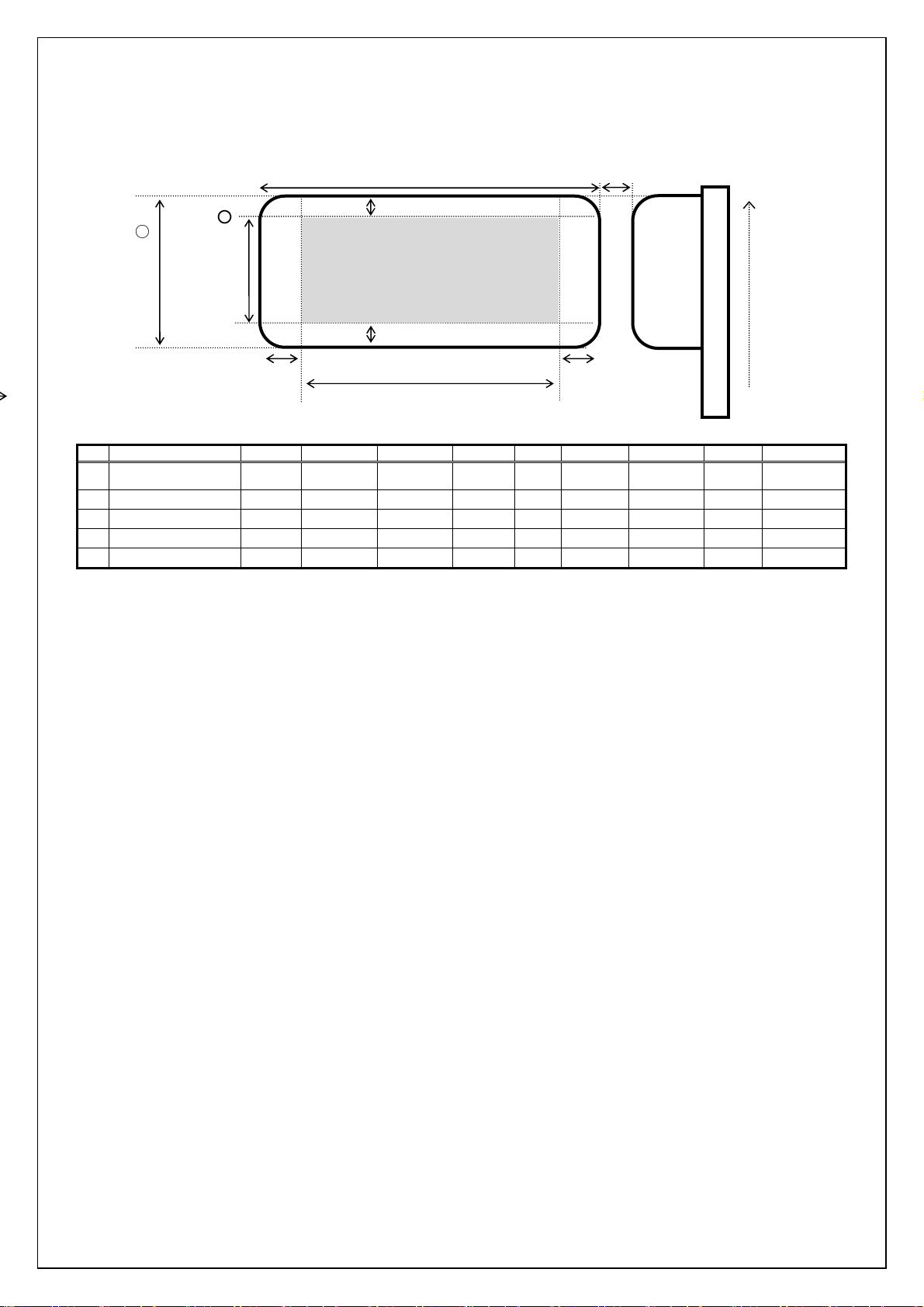
Below are th
p
g
e print areas for each media
Print area
○
1
Label width
○
7
Height of
rintable ran
e
○5Left margin
1
RD 51mm×26mm
2
RD 76mm×26mm
3
RD 102mm×50mm
4
RD 102mm×152mm
5
RD 102mm
The maximum length of continuous length label is 1 meter.
2
○
Label length
3
○
Top margin
○9Label spacing
Thermal head
No.1296
Printable range
4
Bottom margin
○
○8Length of printable range
Media ID.
01A6 50.8mm 25.6mm 1.5mm 3mm 47.8mm 19.6mm 3.0mm 677 ~ 1240
01A5 76.2mm 25.6mm 1.5mm 3mm 73.2mm 19.6mm 3.0mm 377 ~ 1240
01A3 101.6mm 49.9mm 1.5mm 3mm 98.6mm 43.9mm 3.0mm 77 ~ 1240
01A4 101.6mm 152.4mm 1.5mm 3mm 98.6mm 146.4mm 6.3mm 77 ~ 1240
019F 101.6mm - 1.5mm 3mm 98.6mm - - 77 ~ 1240
○1 ○2 ○3○4 ○5○
6
○
Right margin
6
○7 ○8 ○9
No.001
Drive head No..
11
Page 12

Characters
This system uses single-byte character codes and is installed with five bit-map fonts
(Brougham, Letter Gothic bold, Brussels, Helsinki, and San Diego), and 3 out-line fonts
(Letter Gothic, Brussels and Helsinki).
Fixed pitch or proportional pitch (PS pitch) can be specified for any of the fonts.
However, there are fonts that are better with a fixed pitch and fonts that are better with a
proportional pitch (PS pitch).
Fixed pitch fonts are: Brougham, Letter Gothic and Letter Gothic Bold.
Proportional pitch fonts are: Brussels, Helsinki, and San Diego.
Each bit-map font has three sizes: 24 dots, 32 dots, and 48 dots.
Each out-line font has 22 sizes: 33 dots-400 dots.
12
Page 13
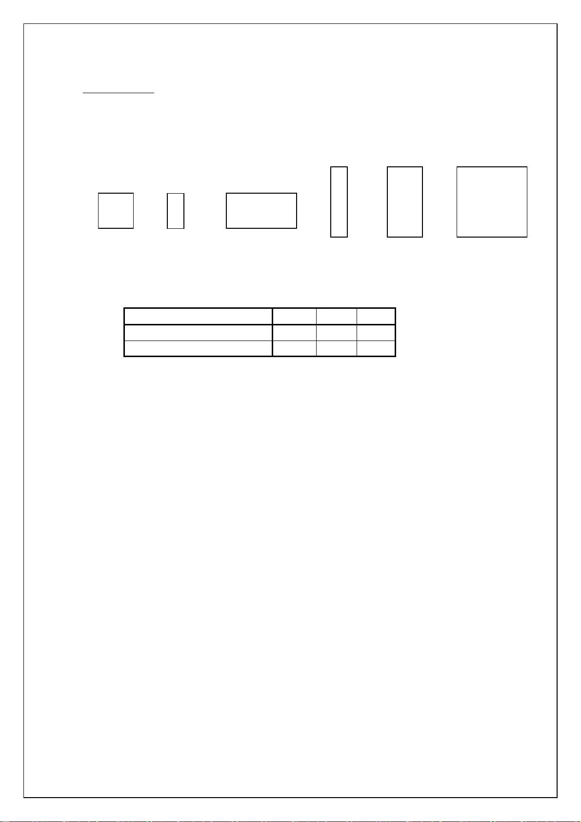
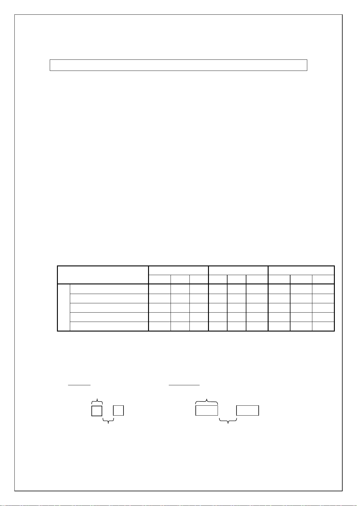
Character sizes
Each font is available in full size, reduced size (half width), double width, double height and
half width, double height, and quadruple size.
Full
size
Half
wid
th
Double width
Double
height
and
half
width
Double
height
Quadruple
size
The actual
character size is slightly smaller than the nominal size (the parameter value
received with the size command). (This varies depending on the font.)
Nominal (dots)
Height (dots)
Width (dots)
24 32 48
21 28 44
11 16 26
The above example is for Brougham (full size, no character styles applied)
The line-drawing characters (┘└ ┤─ ├ │ ┼ ┬ ┐┌ , etc.) and shaded characters have the
Brougham font applied regardless of the specified font and pitch setting (proportional or
fixed).
13
Page 14
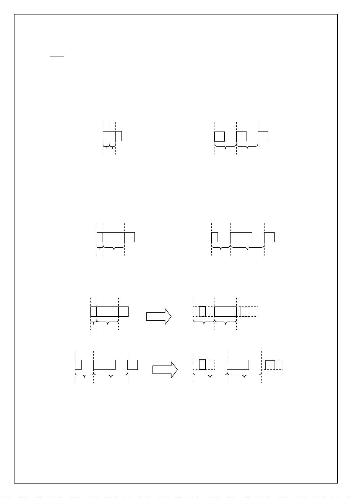
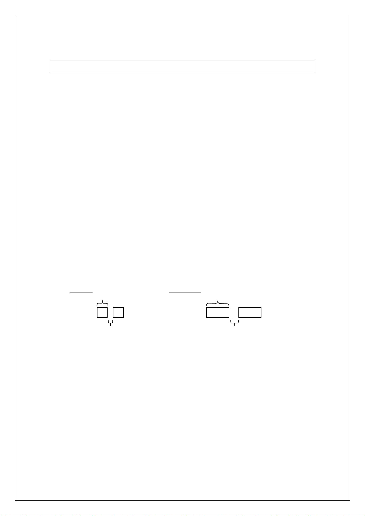
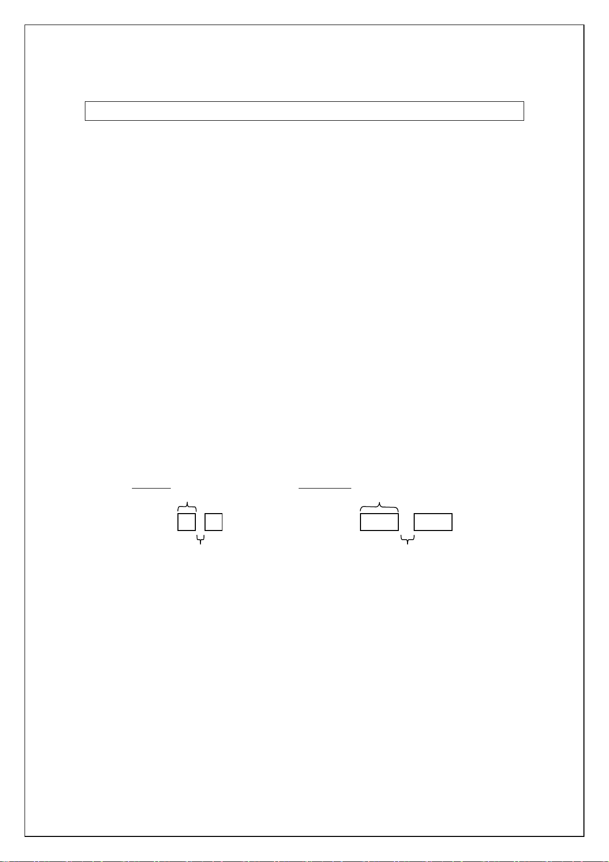
Pitch
Pitch refers to the spacing between neighboring characters.
When characters are arranged with a fixed pitch, they will be evenly spaced.
If characters extend over several lines, they will align in straight rows.
c
b a
a
b c
When characters are arranged with a proportional pitch, the spacing will vary depending on
the character.
(For example, "W" is wide but "I" is narrow.)
As a result, the excess space between characters is eliminated and the text appears more
compact.
If a fixed pitch is applied to a font that is better with a proportional pitch, all characters are
given the same width as the widest character in the font.
Fixed spacing
w
Variable spacing
w
Variable spacing
Fixed spacing
C I
C I
Fixed spacing
w
Variable spacing
w
C I
C I
This makes it possible to evenly space the characters of a proportional-pitch font without
having to change the font.
If a proportional pitch is applied to a font that is better with a fixed pitch, all characters are
given the same width, appearing the same as with a fixed pitch.
14
w
Variable spacing
C I
Fixed spacing
w
C I
Page 15
Print position
A
p
A
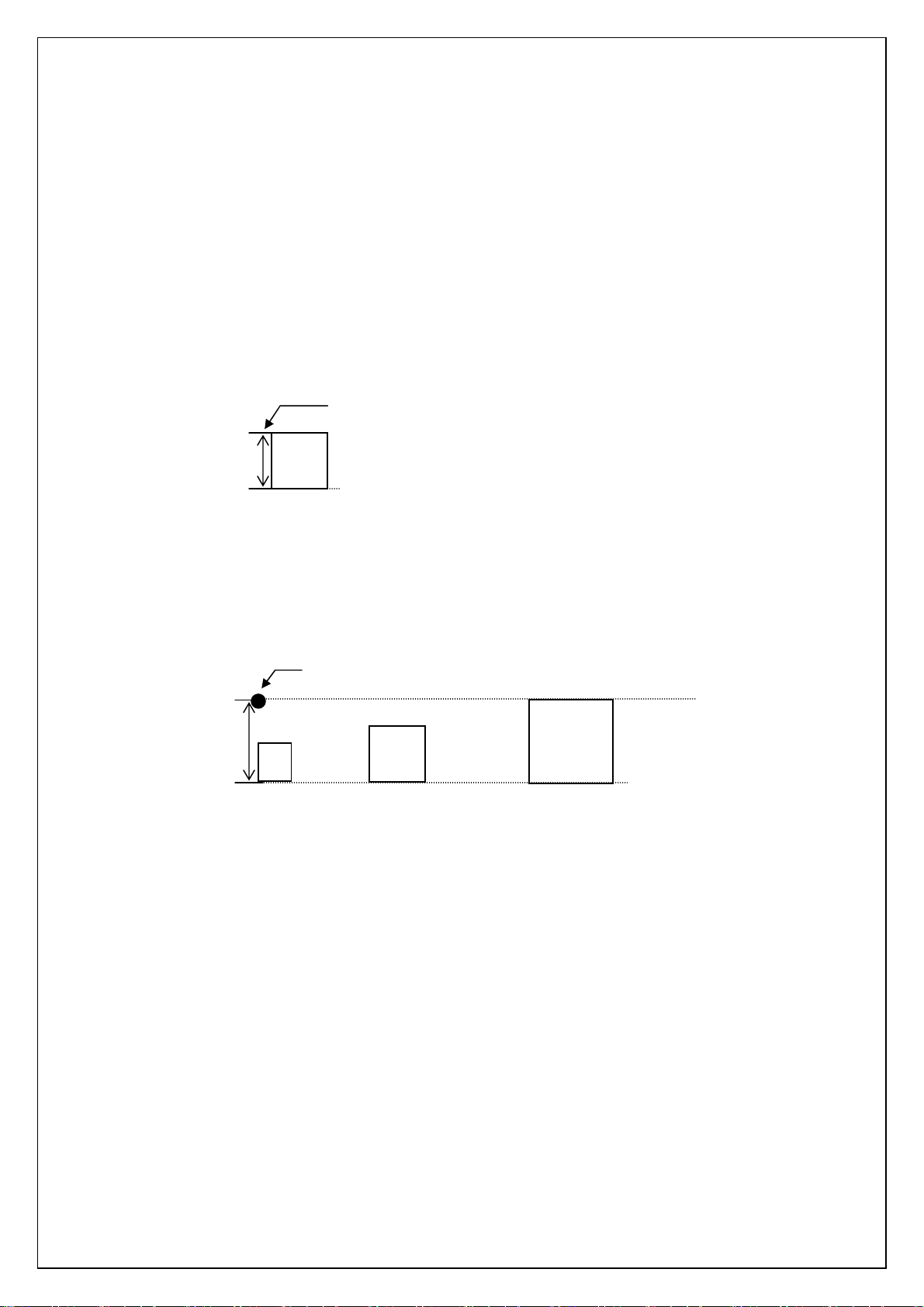
The print position is the standard position for printing characters, bitmaps, and bar codes.
There is a horizontal print position and vertical print position, which are the reference points
for vertical position movement and horizontal position movement.
Characters are arranged with their top edges aligned with the print position.
The baseline of each character is the bottom edge of the character, regardless of size, font,
etc.
Print position
All
characters on a single line are printed at baseline positions that are the same for each
character.
When characters of different heights are mixed together, they are aligned with the baseline
of the tallest character on the line.
Underlin
A
es are drawn 4 dots below the baseline position.
Baseline position
Print
osition
A
Baseline position
15
Page 16

Bitmap
These types of image data are treated in the same way as characters and are printed with
the bottom edge of the image aligned with the baseline.
Same line
・Characters and images are considered to be on the same line, even if tabs are inserted.
・Horizont
s, bar codes, downloaded images
al movement to the right between characters or images is regarded as being on
the same line, however horizontal movement to the left is regarded as being on separate
lines if wrapping occurs.
16
Page 17

Line feed amount
The amount of line feed is the amount of vertical movement from the print position of one
line to the print position of the next line.
HHHHHHHHHHHHH
HHHHHHHHHHHHH
HHHHHHHHHHHHH
The line feed amount is set with ESC 0, ESC 2, ESC A, and ESC 3.
・Within the same line of text, the tallest character is determined and the baseline is moved
so that the top edge of that character is at the vertical print position.
・The tallest character on that line becomes the line height.
・If there is underlining, 4 dots are added to the line height.
・If the line height is greater than the set line feed amount, the line height is used as the
actual line feed amount.
In this way, even if the set for line feed amount is small, the upper and lower lines will not
overlap.
Line feed amount
17
Page 18
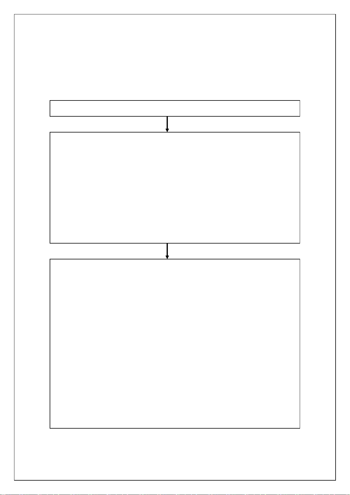
Document creation flow
Below is an explanation of the flow for creating documents.
A Switch command mode (ESC i a) Initialize (ESC @)
B Format Settings
1. Select landscape orientation (ESC i L)
2. Specify page length (ESC ( C)
3. Specify print area
Specify page format (ESC ( c)
Left/right margins (ESC I, ESC Q)
4. Specify line feed amount (ESC 0, ESC 2, ESC 3, ESC A)
5. Specify tab positions
Specify horizontal tab position (ESC D)
Specify vertical tab position (ESC B)
C Print Operations
1. Specify print position
Specify vertical position (ESC ( v, ESC ( V, VT, ESC J)
Specify horizontal position (ESC $, ESC \, HT, ESC a)
2. Transfer print data (one line)
Transfer necessary text operation codes (see D), bit images, bar codes, and
3. End of line, feed paper (CR, LF)
4. Repeat 1–3 above.
5. End of page, specify cutting (ESC i C), feed page (FF)
6. Repeat 1–6 above.
7. End of document
ddd
downloaded data (see E).
18
Page 19
D Text operations
1. Specify character set
Select font (ESC k)
Select character code (ESC t)
Select international character set (ESC R)
Specify character size (ESC X)
Character spacing (ESC P, ESC M, ESC g, ESC SP)
2. Character style (ESC 4, ESC 5, ESC E, ESC F, ESC G,
3. Character code
Repeat 1–3 above as necessary.
ESC H, ESC W, SO, ESC SO, SI, ESC SI
DC2, DC4, ESC -, ESC !)
E Bit image (ESC *, ESC K, ESC L, ESC Y, ESC Z)
Bar code (ESC i B)
2D bar code (ESC i Q, ESC i V, ESC i D, ESC i M)
Downloaded data (ESC i F)
Downloaded image data must first be downloaded and saved on the main
unit.
19
Page 20
Control command details
Character/style selection commands
ESC R Select international character set
[ASCII] ESC R n
[Decimal] 27 82 n
[Hexadecimal] 1B 52 n
[Parameters] 0 ≤ n ≤ 13,64
[Description]
・Selects the international character set and changes some of the character codes in the
code table according to the value of n.
n=0: U.S.A.
n=1: France
n=2: Germany
n=3: U.K.
n=4: Denmark
n=5: Sweden
n=6: Italy
n=7: Spain
n=8: Japan
n=9: Norway
n=10: Denmark II
n=11: Spain II
n=12: Latin America
n=13: South Korea
n=64: Legal
・The following 12 codes are changed.
23h,24h,40h,5Bh,5Ch,5Dh,
5Eh, 60h, 7Bh, 7Ch, 7Dh, 7Eh
・The default setting is n = 0 (U.S.A.)
[Example]
Code
5Ch ESC R 08h 5Ch FF
Print result
\ ¥
20
Page 21
ESC q Select character style
[ASCII] ESC q n
[Decimal] 27 113 n
[Hexadecimal] 1B 71 n
[Parameters] 0 ≤ n ≤ 3
[Description]
・Selects the character style.
n=0: Cancel (normal characters)
n=1: Outline
n=2: Shadow
n=3: Shadow and outline
[Example]
Code
ABC ESC q 02h ABC ESC q 00h ABC FF
Print result
ABC
ABC
A
C
B
21
Page 22
ESC k Select font
[ASCII] ESC k n
[Decimal] 27 107 n
[Hexadecimal] 1B 6B n
[Parameters] 0 ≤ n ≤ 4, 9 ≤ n ≤ 11
[Description]
・Selects the font.
<Bit-map fonts>
n=0 ···Brougham (fixed pitch)
n=1 ···Letter Gothic bold (fixed pitch)
n=2 ···Brussels (proportional pitch)
n=3 ···Helsinki (proportional pitch)
n=4 ···San Diego (proportional pitch)
<Out-line fonts>
n=9 ···Letter Gothic(fixed pitch)
n=10 ···Brussels(proportional pitch)
n=11 ··· Helsinki(proportional pitch)
・The default value is n=0 Brougham (fixed pitch).
・In case font is changed from bit-map fonts to out-line fonts, character size is changed to
default setting(42dots).
・In case font is changed from out-line fonts to bit-map fonts, character size is changed to
default setting(32dots).
ESC t Select character code table
[ASCII] ESC t n
[Decimal] 27 116 n
[Hexadecimal] 1B 74 n
[Parameters] n=0,1,2
[Description]
・From the three built-in character code tables, selects the character code table used.
・n=0: Standard character code table
・n=1: Eastern European character code table
・n=2: Western European character code table
・n=3: (Spare)
・The default setting is n = 0.
22
Page 23
Text printing commands
ESC 4 Apply italic style
[ASCII] ESC 4
[Decimal] 27 52
[Hexadecimal] 1B 34
[Parameters] None
[Description]
・Applies italic character style.
・This command is valid anywhere in a text line.
ESC 5 Cancel italic style
[ASCII] ESC 5
[Decimal] 27 53
[Hexadecimal] 1B 35
[Parameter] None
[Description]
・Cancels italic character style.
・This command is valid anywhere in a text line.
[Example]
Code
ABC ESC 4 DEF ESC 5 GHI FF
Print result
ABCDEFGHI
23
Page 24
ESC E Apply bold style
[ASCII] ESC E
[Decimal] 27 69
[Hexadecimal] 1B 45
[Parameters] None
[Description]
・Prints subsequent print data bold.
・This command is valid anywhere in a text line.
ESC F Cancel bold style
[ASCII] ESC F
[Decimal] 27 70
[Hexadecimal] 1B 46
[Parameters] None
[Description]
・Cancels the bold style.
・This command is valid anywhere in a text line.
[Example]
Code
ABC ESC E DEF ESC F GHI FF
Print result
ABCDEFGHI
24
Page 25
ESC G Apply double-strike printing
[ASCII] ESC G
[Decimal] 27 71
[Hexadecimal] 1B 47
[Parameters] None
[Description]
・Prints subsequent print data bold.
・This command is valid anywhere in a text line.
ESC H Cancel double-strike printing
[ASCII] ESC H
[Decimal] 27 72
[Hexadecimal] 1B 48
[Parameters] None
[Description]
・Cancels bold style.
・This command is valid anywhere in a text line.
[Example]
Code
ABC ESC G DEF ESC H GHI FF
Print result
ABCDEFGHI
25
Page 26
ESC P Specify pica pitch
[ASCII] ESC P
[Decimal] 27 80
[Hexadecimal] 1B 50
[Parameters] None
[Description]
・Prints subsequent data with pica pitch (10 characters/inch).
・The character spacing is 30 dots (=300 dots/10 characters).
・If the character width is 30 dots or less, the character spacing is set to 30 minus the
character width.
・If the character width exceeds 30 dots, the character spacing is set to the character
width. (The space between characters is 0 dot.)
In this case, the pitch does not exactly equal the pica pitch.
・With double-width characters, the character spacing is doubled (60 dots).
・With half-width characters, the character spacing is cut in half (15 dots).
・When the character spacing is changed with ESC SP, the setting is updated.
・This command is invalid when proportional pitch is selected.
・In out-line fonts, the space between character is 0 dot.
Setting (dots)
Width (dots)
Brougham
Letter Gothic bold
Brussels
Helsinki
San Diego
Full width Double width Half width
24 32 48 24 32 48 24 32 48
11 16 26 22 32 52 6 8 13
10 14 22 20 28 44 5 7 11
25 35 56 50 70 112 13 18 28
21 28 44 42 56 88 11 14 22
24 35 57 48 70 114 12 18 29
The above table refers to characters with a fixed pitch. (Applying styles may
increase the size.)
[Example] For a 24-dot font at full width
Full width Double width
24 dots
48 dots
A
B
A B
6 dots
26
12 dots
Page 27
ESC M Specify elite pitch
[ASCII] ESC M
[Decimal] 27 77
[Hexadecimal] 1B 4D
[Parameters] None
[Description]
・Prints subsequent data with elite pitch (12 characters/inch).
・Character width is 25 dots (=300 dots/12 characters).
・If the character width is 25 dots or less, the character spacing is set to 25 minus the
character width.
・If the character width exceeds 25 dots, character spacing is set to character width.
(Character spacing is 0 dot.)
In this case, the pitch does not exactly equal the pica pitch.
・With double-width characters, the character spacing is doubled (50 dots).
・With half-width characters, the character spacing is reduced to 13 dots.
・When the character spacing is changed with ESC SP, the setting is updated.
・This command is invalid when proportional pitch is selected.
・In out-line fonts, the space between character is 0 dot.
[Example] For a 24-dot font at full width
Full width Double width
24 dots
A B
48 dots
A B
1 dots
2 dots
27
Page 28
ESC g Specify micron pitch
[ASCII] ESC g
[Decimal] 27 103
[Hexadecimal] 1B 67
[Parameters] None
[Description]
・Prints subsequent data with micron pitch (15 characters/inch).
・Character spacing is 20 dots (=300dots/15 characters).
・If the character width is 20 dots or less, character spacing is set to 20 minus the
character width.
・If the character width exceeds 20 dots, character spacing is set to character width. (The
character spacing is 0 dot.)
In this case, the pitch does not exactly equal the micron pitch.
・With double-width characters, the character spacing is doubled (40 dots).
・With half-width characters, the character spacing is reduced to 10 dots.
・When the character spacing is changed with ESC SP, the setting is updated.
・This command is invalid when proportional pitch is selected.
・In out-line fonts, the space between character is 0 dot.
[Example] For an 11-dot font at full width
Full width Double width
11 dots
A B
22 dots
A B
9 dots
18 dots
28
Page 29
ESC p Specify proportional characters
[ASCII] ESC p n
[Decimal] 27 112 n
[Hexadecimal] 1B 70 n
[Parameters] n=0,1,48(“0”),49(“1”)
[Description]
・Specifies proportional characters.
・n=1 or 49(“1”) applies proportional characters.
・n=0 or 48(“0”) cancels proportional characters.
・When proportional characters are specified, the character spacing set with ESC SP is
retained as is.
29
Page 30

ESC W Specify double width characters
[ASCII] ESC W n
[Decimal] 27 87 n
[Hexadecimal] 1B 57 n
[Parameters] n=0,1 or 48(“0”),49(“1”)
[Description]
・Specifies double-width characters.
・n = 1 or 49(“1”) specifies double-width characters.
・n = 0 or 48(“0”) cancels double-width characters.
・Double-width characters specified with this code is not cancelled with the DC4 or FS
DC4 code or line feed.
・Canceling double width characters mode will also cancel half width mode.
[Example]
Code
ABC ESC W 1 ABC ESC W 0 ABC FF
Print result
ABC
ABC
ABC
30
Page 31

SO Specify auto-cancelling enlarg
[ASCII] SO
[Decimal] 14
[Hexadecimal] 0E
[Parameters] None
[Description]
・Prints subsequent data at double width.
・This mode is cancelled with DC4, LF, VT, FF, or an automatic line feed.
・This mode is cancelled with ESC $ or ESC \.
・This mode can also be cancelled with ESC W+0.
ESC SO Specify auto-cancelling enlar
[ASCII] ESC SO
[Decimal] 27 14
[Hexadecimal] 1B 0E
ed characters
ged characters
[Parameters] None
[Description]
・Same as SO
[Example]
Code
ABC ESC SO ABCDEFGHIJK…XYZ FF
Print result
ABC
XYZ
ABCDEFGHIJK…
(Automatic line feed)
31
Page 32

SI Specify reduced characters
[ASCII] SI
[Decimal] 15
[Hexadecimal] 0F
[Parameters] None
[Description]
・ Prints subsequent data at half width.
ESC SI Specify reduced characters
[ASCII] ESC SI
[Decimal] 27 15
[Hexadecimal] 1B 0F
[Parameters] None
[Description]
・Same as SI
DC2 Cancel reduced characters
[ASCII] DC2
[Decimal] 18
[Hexadecimal] 12
[Parameters] None
[Description]
・Cancels reduced characters specified with SI.
32
Page 33

DC 4 Cancel auto-cancelling double
[ASCII] DC4
[Decimal] 20
[Hexadecimal] 14
[Parameters] None
[Description]
・Cancels double-width characters specified with ESC SO or SO.
・Does not cancel a setting made with ESC W.
[Example]
Code
ABC ESC SO ABCDEF DC4 GHIJK FF
Print result
ABC
ABCDEF
-width characters
GHIJK
33
Page 34

ESC – Applies/cancels underlining
[ASCII] ESC - n
[Decimal] 27 45 n
[Hexadecimal] 1B 2D n
[Parameters] n=0,1,2,3,4 or 48(“0”),49(“1”),50(“2”),51(“3”),52(“4”)
[Description]
Applies or cancels underlining.
. n = 4 or 52(“4”) applies 4-dot-wide underlining.
. n = 3 or 51(“3”) applies 3-dot-wide underlining.
. n = 2 or 50(“2”) applies 2-dot-wide underlining.
. n = 1 or 49(“1”) applies 1-dot-wide underlining.
. n = 0 or 48(“0”) cancels underlining.
. This command is valid anywhere in a text line.
. Underlining printed by this code forms a continuous underline.
・Spaces between characters and words are also underlined.
・Areas defined by specifying an absolute horizontal position (ESC $) or relative
horizontal position (ESC \) are not underlined.
・4/300 inch (4 dots) is added to the line feed amount for lines that include underlined
characters.
・With 1-dot-wide underlining, the underline is positioned as follows:
2/300 inch (2 dots) below the characters
・With 2-dot-wide underlining, the underline is positioned as follows:
Between 2/300 inch (2 dots)
and 3/300 inch (3 dots) below the characters
・With 3-dot-wide underlining, the underline is positioned as follows:
Between 1/300 inch (1 dot)
and 3/300 inch (3 dots) below the characters
・With 4-dot-wide underlining, the underline is positioned as follows:
Between 1/300 inch (1 dot)
and 4/300 inch (4 dots) below the characters
ABCDE ABCDE
(1-dot width) (3-dot width)
ABCDE
34
Page 35

ample]
[Ex
Code
ABC ESC - 1 ABC ESC - 0 ABC FF
Print result
ABCABC
ABC
35
Page 36

ESC ! Global formatting
[ASCII] ESC ! n
[Decimal] 27 33 n
[Hexadecimal] 1B 21 n
[Parameters] 0 ≤ n ≤ 255
[Description]
・Specifies a combination of print modes.
・Specifies modes depending on the bit value of n.
・When the ESC ! code is used, a combination of multiple print modes can be specified at
one time.
・The priority order is: Bit 5 > Bit 2
・Bit 0 is available only if Bit 1 is 0.
・Selected character styles are canceled, and the characters return to the normal style.
・Canceling double width characters mode will also cancel half width mode.
Bit 7 6 5 4 3 2 1 0
1 Underline Italics Double width Double height Bold Reduced Proportional 12 cpi
0 Cancel Cancel Cancel Cancel Cancel Cancel Cancel 10 cpi
[Example] Specifying underlining and double-width characters at the same time.
Code
ABC ESC ! A0h ABC ESC ! 00h ABC FF
Print result
ABC
ABC
ABC
36
Page 37

ESC SP Specify character spacing
[ASCII] ESC SP n
[Decimal] 27 32 n
[Hexadecimal] 1B 20 n
[Parameters] 0 ≤ n ≤ 127
[Description]
・Specifies the character spacing.
・n indicates the number of dots.
・The default setting is 0 dot.
・With double-width characters, the character spacing is doubled, with half-width
characters, it is halved.
37
Page 38

ESC X Specify character size
[ASCII] ESC X m nL nH
[Decimal] 27 88 m nL nH
[Hexadecimal] 1B 58 m nL nH
[Parameters] Character width : The value of m is irrelevant.
character size:
<Bit-map fonts> nL = 24, 32, 48 dots
Available only when nH=0
<Out-line fonts>
nL=33, 38, 42, 46, 50, 58, 67, 75,
nL=83, 92, 100, 117, 133, 150,
nL=167, 200 233
nH =0
nL=11, 44, 77, 111, 144
Available only when nH = 1
[Description]
・This command is used only to change the size.
・Outline must not be specified.
・Character width cannot be set.
・The character size is set to n = nL + nH * 256 dots.
・Width and height are the same.
・In case of bit-map fonts, only n = 24, 32, and 48 are available. In case of out-line fonts,
only n = 33, 38, 42, 46, 50, 58, 67, 75, 83, 92, 100, 117, 133, 150, 167, 200, 233, 267,
300, 333, 367, 400 are available.
・The commands for specifying enlarged characters, reduced characters, character
spacing (SO, ESC W, ESC !, ESC SP) remain available.
[Example] ABC in 24-dot font and DEF in 48-dot font
Code
ESC X 00h 18h 00h ABC
ESC X 00h 30h 00h DEF FF
Print result
ABC
38
DEF
Page 39

Line feed commands
ESC 0 Specify line feed of 1/8 inch
[ASCII] ESC 0
[Decimal] 27 48
[Hexadecimal] 1B 30
[Parameters] None
[Description]
. Specifies a line feed of 1/8 inch (about 0.32 cm).
. Specifies a line feed of 38/300 inch (= 38 dots).
ESC 2 Specify line feed of 1/6 inch
[ASCII] ESC 2
[Decimal] 27 50
[Hexadecimal] 1B 32
[Parameters] None
[Description]
. Specifies a line feed of 1/6 inch (about 0.42 cm).
. Specifies a line feed of 50/300 inch (= 50 dots).
ESC 3 Specify minimum line feed
[ASCII] ESC 3 n
[Decimal] 27 51 n
[Hexadecimal] 1B 33 n
[Parameters] 0 ≤ n ≤ 255
[Description]
. Specifies a line feed of n/300 inch per line.
. The line feed unit is 1 dot.
39
Page 40

ESC A Specify line feed of n/60 inch
[ASCII] ESC A n
[Decimal] 27 65 n
[Hexadecimal] 1B 41 n
[Parameters] 0 ≤ n ≤ 255
[Description]
・Specifies a line feed of n/60 inch.
・The line feed unit is 5 dots.
40
Page 41

Horizontal direction movement commands
ESC l Specify left margin
[ASCII] ESC l n
[Decimal] 27 108 n
[Hexadecimal] 1B 6C n
[Parameters] 0 ≤ n ≤ 255
0 ≤ left margin < right margin
[Description]
・The left margin and the right margin use the left edge of the physically printable area as
the reference.
・The space between the left edge of the physically printable area and the set number of
columns is set as an unprinted area. The left margin position is the right edge of the
specified column. (Character width * n)
・The setting is in the range 0 ≤ (character width * n) ≤ x. Settings outside that range are
ignored. However, x is a value dependent on the media.
・The area between the left edge (first column) to the nth column is specified as an
unprinted area.
・The position
set) from the left edge.
The character width when specifying the margin includes the settings for specifying
character spacing, character spacing for full-width characters or half-width characters. In
addition, when pitches of 10 cpi (= 30 dots), 12 cpi (= 25 dots), or 15 cpi (= 20 dots),
reduced characters, or double-width characters are specified, that character width is
considered the unit.
However, increases in the character width due to character styles are not applied.
of the left margin is the character width * n (at the time that the left margin is
41
Page 42

Columns
Left edge Left margin position
1 2 3 4 5 6 7 8 9 10 11 12 13 14
Right margin position
15 16
・
・
Unprinted
area
Left margin setting
Right margin setting
Example: Left margin = Column 5; right margin = Column 14
Print area
Printable area
Unprinted
area
42
Page 43

・The horizont
・If the left margin setting is not at the beginning of the line, the left margin is set after a line
feed.
The beginning of the line indicates the left margin position for left alignment; for right and
center alignment, it means that no image or character is entered on the line.
・Even if the character width is changed after the left margin is set, the left margin position
does not change.
・Any left margin setting that puts the left margin position to the right of the right margin
position is ignored.
・When setting the left margin, set it at least one column (10 cpi = 30 dots) smaller than the
right margin.
[(the character width * n at the setting) > (number of dots of right margin - 30 dots) -->
the setting will be ignored.]
・If the difference between the right margin position and the left margin position is less than
one character, that character is ignored.
・When proportional pitch is specified with the ESC p command, a character width of 10
cpi (= 30 dot) is applied.
al direction print position is moved to the left margin position.
・If the print media is continuous length label, the print direction is landscape, and the page
length is not specified, commands specifying the left margin are ignored.
[Example] The left margin is set to Column 3.
Code
ABC CR ESC l 03h EFGHIJ FF
Print result
ABC
EFGHIJ
43
Page 44

ESC Q Specify right margin
[ASCII] ESC Q n
[Decimal] 27 81 n
[Hexadecimal] 1B 51 n
[Parameters] 1≤n≤255
Left margin < character width * n at time of setting ≤ printable area
[Description]
・The left margin and the right margin use the left edge of the physically printable area as
the reference.
・The right margin position is the right edge of the set column. (Character width * n)
・The setting is in the range 0 ≤ (character width * n) ≤ x. ettings outside that range are
ignored. However, x is a value dependent on the media.
・Left margin ≤ print area < right margin
・The position of the right margin is the character width * n (at the time that the right margin
is set) from the left edge.
The character width when specifying the margin includes the settings for specifying
character spacing, character spacing for full-width characters or half-width characters. In
addition, when pitches of 10 cpi (= 30 dots), 12 cpi (= 25 dots), or 15 cpi (= 20 dots),
reduced characters, or double-width characters are specified, that character width is
considered the unit.
However, increases in the character width due to character styles are not applied.
・The horizontal printing position is moved to the left margin position.
・If the right margin setting is not at the beginning of the line, the right margin is set after a
line feed.
The beginning of the line indicates the left margin position for left alignment; for right and
center alignment, it means that no image or character is entered on the line.
・Even if the character width is changed after the right margin is set, the right margin
position does not change.
・Any right margin setting that puts the right margin position to the left of the left margin
position is ignored.
・When setting the right margin, set it at least one column (10 cpi = 30 dots) greater than
the left margin.
(If the character width * n at the time of setting < (left margin + 30 dots), the setting is
ignored.)
・If the dif
character, that character is ignored.
44
ference in the right margin position and the left margin position is less than one
Page 45

・When pro
cpi (= 30 dot) is applied.
・If the print media is continuous length label, the print direction is landscape, and the page
length is not specified, commands specifying the right margin are ignored.
portional pitch is specified with the ESC p command, a character width of 10
45
Page 46

CR Carriage return
[ASCII] CR
[Decimal] 13
[Hexadecimal] 0D
[Parameters] None
[Description]
・Finalizes the input of a line and waits for input of the next line.
・The next print position is the beginning of the next line.
・A line feed command immediately after the carriage return is ignored.
Specifying auto-cancelling double-width characters with SO or ESC SO is cancelled.
・Same processing as LF.
46
Page 47

ESC D Specify horizontal tab position
[ASCII] ESC D [n]k NUL
[Decimal] 27 68 [n]
[Hexadecimal] 1B 44 [n]
k
k
0
00h
[Parameters] 1≤n≤255
0≤k≤32
[Description]
・The position of the horizontal tab is the character width * n (at the time that the
horizontal tab is set) from the left margin.
・Enter n values in ascending order and end the setting with NUL.
・If an n value is smaller than the previous one, the tab setting is finished.
・Even if the character width is changed after the horizontal tab positions are set, those
horizontal tab setting positions do not change.
・ESC D NUL deletes all horizontal tab positions.
・If the left margin is moved, the horizontal tab positions are moved along with it.
・Up to 32 horizontal tab positions can be set. However, horizontal tab positions beyond
the right margin are invalid and only become valid when a change in the right margin
setting or left margin setting moves the print area to those tab positions.
・The character width at the time that the horizontal tabs are set includes the command
settings for specifying character spacing, full-width character spacing, or half-width
character spacing. In addition, when the 10 cpi, 12 cpi, or15 cpi pitch, reduced
characters, or double-width characters are specified, that character width is considered
the unit.
・When proportional pitch is specified with ESC p, horizontal tab positions are set at 10
cpi.
・When the unit is switched on, horizontal tab positions are set every 8 columns at 10 cpi.
Even if the character width is changed before the horizontal tab positions are set, the
horizontal tab positions do not change.
47
Page 48

Left edge Left margin position Tab position Tab position
・
Column
1 2 3 4 5 6 7 8 9 10 11 12 13 14 15 16
1 2 3 4 5 6 7 8 9 10 11 12 13 14
・
HT code
HT code
Right margin position
・
Unprinted area
Printable area
Example: After the left margin is set to Column 3 and the right
margin to Column 15, horizontal tabs are set at Column 5 and
Column 10, and an HT is performed.
HT Apply horizontal tab
[ASCII] HT
[Decimal] 9
[Hexadecimal] 09
[Parameters] None
[Description]
・Moves the horizontal print position to the nearest horizontal tab position to the right of
the input position.
・If there is no horizontal tab position to the right of the input position or the next
horizontal tab position is beyond the right margin, the HT command is ignored.
・When underlining is specified, no underline is applied between the current position and
Unprinted area
the next horizontal tab position.
・When the unit is switched on, horizontal tab positions are set every 8 columns at 10 cpi.
Even if the character width is changed before the horizontal tab positions are set, the
horizontal tab positions do not change.
・This command is available only with left alignment.
[Example] Specifying horizontal tabs at Column 4, Column 8, and Column 12, and applying
a horizontal tab
Code
ESC D 04h 08h 0Ch 00h
123456789012 CR A HT B HT C HT D FF
Print result
123456789012
A B C D
48
Page 49

ESC $ Specify absolute horizont
[ASCII] ESC $ n1 n2
[Decimal] 27 36 n1 n2
[Hexadecimal] 1B 24 n1 n2
[Parameters] 0≤n1≤255 ,0≤n2≤255
[Description]
・Specifies in dots the absolute print position for the next data.
・An absolute print position specifies the next print position as the number of dots from
the left margin.
・n1 and n2 indicate the number of dots from the left margin. (Number of dots = n1 +
256*n2)
・The dot spacing is calculated as 1/300 inch.
・The maximum number of dots that can be specified with n1 and n2 depends on the
media.
・This command is available only with left alignment.
al position
ESC \ Specify relative horizontal position
[ASCII] ESC \ n1 n2
[Decimal] 27 92 n1 n2
[Hexadecimal] 1B 5C n1 n2
[Parameters] 0≤n1≤255,0≤n2≤255
[Description]
・Specifies in dots the horizontal print position as a relative position from the current
position.
・A relative position specifies the next print position as the number of dots from the
current position.
・n1 and n2 indicate the number of dots from the current position. (Number of dots = n1 +
256*n2)
・The dot spacing is calculated as 1/300 inch.
・Left margin position ≤ horizontal position after moving < right margin position
Horizontal position after moving = n1 + n2*256
・The specified value for moving to the left is expressed as the 2's complement. It is
determined by the following equation.
n1 + n2 * 256 = 65536 - distance of actual movement
・This comma
49
nd is available only with left alignment.
Page 50

ESC a Specify alignment
[ASCII] ESC a n
[Decimal] 27 97 n
[Hexadecimal] 1B 61 n
[Parameters] 0≤n≤3 or “0”≤n≤“3”
[Description]
・The data is printed aligned as follows according to the value of n.
n=0 or 48(“0”) specifies left alignment
n=1 or 49(“1”) specifies center alignment
n=2 or 50(“2”) specifies right alignment
n=3 or 51(“3”) specifies nothing
・The default setting is n = 0.
・Data is aligned between the left and right margins with CR, LF, and FF code input and
buffer printing.
・If the alignment setting is not at the beginning of the line, the alignment is set after a line
feed.
The beginning of the line indicates the left margin position for left alignment;
for right and center alignment, it means that no image or character is entered on the line.
・HT, ESC \, ESC $ are ignored when n = 1 or n = 2.
・If the print media is continuous length label, the print direction is landscape, and the
page length is not set, commands specifying alignment are ignored.
50
Page 51

Vertical movement commands
LF Line feed
[ASCII] LF
[Decimal] 10
[Hexadecimal] 0A
[Parameters] None
[Description]
・Feeds the paper by the amount set with the commands specifying the line feed amount
(ESC 0, ESC 2, ESC 3, ESC A).
・The print position moves to the beginning of the next line.
・The default value is a 48-dot line feed.
・When a carriage return comes immediately after a line feed, the carriage return is
ignored.
・Automatic cancellation of double-width characters with SO or ESC SO is cancelled.
・Same processing as CR
FF Page feed
[ASCII] FF
[Decimal] 12
[Hexadecimal] 0C
[Parameters] None
[Description]
・Starts the printing.
・Data line of the characters and commands entered before this command is cleared after
printing.
・At this time, automatic cancellation of double-width characters specified with SO or ESC
SO is cancelled.
51
Page 52

ESC J Forward paper feed
[ASCII] ESC J n
[Decimal] 27 74 n
[Hexadecimal] 1B 4A n
[Parameters] 0≤n≤255
[Description]
・Ends input for the current line and moves the vertical print position forward by n/300
inch (=1 dot).
・If the bottom margin setting is exceeded, printing starts.
・With left alignment, the print position for the next line is the end position of the current
line. (The horizontal position does not move to the left margin.)
With right alignment and center alignment, the horizontal position moves to the
beginning of the line.
・Automatic cancellation of double-width characters specified with SO or ESC SO is
cancelled.
Abcdefg
ABC
SDFASG
Abcdefg
ABC
SDFASG
Abcdefg
ABC
SDFASG
Left alignment
Center alignment
Right alignment
Example: Performing a forward paper feed after the second row
52
Page 53

ESC B Specify vertical tab position
[ASCII] ESC B [n]k NUL
[Decimal] 27 66 [n]
[Hexadecimal] 1B 42 [n]
k
k
0
00h
[Parameters] 1≤n≤255
0≤k≤16
[Description]
・The position of the vertical tab is the line feed amount * n (at the time that the vertical
tab is set) from the top margin.
・Enter n values in ascending order and end the setting with NUL.
・If an n value is smaller than the previous one, the tab setting is finished.
・Up to 16 vertical tabs can be set.
・To cancel all vertical tab positions, use ESC B NUL.
・Vertical tab positions can be set regardless of the setting of the bottom margin position.
However, any vertical tab position outside the print area (beyond the bottom margin
position) is invalid and only becomes valid when a change in the top or bottom margin
position moves the print area to that vertical tab.
・Move to a vertical tab position with VT.
・When changing vertical tab positions, they must all be reset.
・If the top margin is moved, the vertical tab positions are also moved by the same
amount.
・Even if the line feed amount is changed after the vertical tab positions are set, those
vertical tab setting positions do not change.
・Performing a VT when no vertical tabs is set is equal to performing a CR.
53
Page 54

A
A
p
VT Apply vertical tab
[ASCII] VT
[Decimal] 11
[Hexadecimal] 0B
[Parameters] None
[Description]
・Moves the print position to the nearest vertical tab position down from the input position.
・The next horizontal print position is the beginning of the line.
・If the next vertical tab position exceeds the bottom margin, or if there is no vertical tab
position set below the current position, performing a VT is equal to performing an FF.
(Movement to the TOF position for the next page)
10
11
12
13
14
15
16
17
18
1 2
3
4
5
6
7
8
9
ABCD
EfghijkL
VT code
bcdefg
VT code
BCDEFG
VT code
aiueo
Line
・
feed
amount
・
Tab position
・
Tab position
Tab position
Example: Vertical tabs are set to Lines 6, 11, and 15, and data is entered while VT is
erformed
・In the default st
ate and when all the vertical tab positions have been cancelled with ESC
B NUL, performing a VT is equal to performing a CR.
・Automatic cancellation of double-width characters with SO or ESC SO is cancelled.
54
Page 55

ESC (V Specify absolute vertical position
[ASCII] ESC ( V nL nH mL mH
[Decimal] 27 40 86 nL nH mL mH
[Hexadecimal] 1B 28 56 nL nH mL mH
[Parameters] nL=2
nH=0
0≤mL≤255
0≤mH≤127
[Description]
・Specifies the vertical print position as an absolute position from the top margin position.
Vertical position = mL + mH * 256 + top margin
・The absolute vertical position is measured from the top margin position at the time.
・If a position exceeding the bottom margin is specified, printing starts.
・There is no restriction on the amount of movement back (upward) from the current
position.
・With left alignment, the print position for the next line is the end position of the current
line. (The horizontal position does not move to the left margin.)
With right alignment and center alignment, the horizontal position moves to the beginning
of the line.
・Automatic cancellation of double-width characters specified with SO or ESC SO is
cancelled.
55
Page 56

ESC (v Specify relative vertical position
[ASCII] ESC ( v nL nH mL mH
[Decimal] 27 40 118 nL nH mL mH
[Hexadecimal] 1B 28 76 nL nH mL mH
[Parameters] nL=2
nH=0
0≤mL≤255
0≤mH≤127
-16384 ≤(mL+mH * 256)≤16383
[Description]
・Specifies the vertical print position as a relative position from the current position.
Vertical position after movement = mL + mH * 256 + current position
・When moving upwards, the specified value is expressed as a 2's complement. It is
determined by the following equation.
mL + mH * 256 = 65536 – amount of actual movement
・Settings moving the print position above the top margin are ignored.
・If a position exceeding the bottom margin is specified, printing starts.
・With left alignment, the print position for the next line is the end position of the current
line. (The horizontal position does not move to the left margin.)
With right alignment and center alignment, the horizontal position moves to the
beginning of the line.
・Automatic cancellation of double-width characters with SO or ESC SO is cancelled.
Abcdefg
ABC
SDFASG
Abcdefg
ABC
SDFASG
Abcdefg
ABC
SDFASG
Left alignment
Center alignment
Right alignment
Example: Specifying a vertical position after the second row and moving to it
56
Page 57

Paper formatting
ESC (c Specify page format
[ASCII] ESC ( c nL nH tL tH BL BH
[Decimal] 27 40 99 nL nH tL tH BL BH
[Hexadecimal] 1B 28 63 nL nH tL tH BL BH
[Parameters] nL=4,nH=0
[Description]
・Specifies settings for the top and bottom margins.
・The physically printable area depends on the media.
The top margin and the bottom margin are set in units of 1/300 inch (= 1 dot) using the
top edge of the physically printable area as the reference.
(The left margin and the right margin use the left edge of the physically printable area as
the reference.)
Top margin = tL + tH * 256
(tL + tH * 256)<(BL + BH * 256)
Top margin < bottom margin
Bottom margin = BL + BH * 256
・The top margin position is the TOF in the vertical direction.
・All text content before this is cleared.
・The character baseline for the first line is 24/300 inch (24 dots) below the top margin.
・When this code is set, previously set top and bottom margins are deleted.
・The standard unit is not used.
・If the print media is continuous length label and, the print direction is landscape, and the
page length is not set, commands specifying the page format are ignored.
57
Page 58

ESC (C Specify page length
[ASCII] ESC ( C nL nH mL mH
[Decimal] 27 40 67 nL nH mL mH
[Hexadecimal] 1B 28 43 nL nH mL mH
[Parameters] nL=2,nH=0
0<(mL+mH * 256)<12000
[Description]
・Specifies the page length.
・ The unit is 1/300 inch (= 1 dot).
Page length = mL + mH * 256
・The current paper position is set as the TOF.
・The top and bottom margins are deleted with ESC ( c.
・All text content before this is cleared.
・The standard unit is not used.
・This command is available only with continuous length label.
Inch, mm, and dot conversion table
inch mm Number of dots
0 0 0
1 25.4 300
2 50.8 600
3 76.2 900
4 101.6 1200
5 127.0 1500
6 152.4 1800
7 177.8 2100
8 203.2 2400
9 228.6 2700
10 254.0 3000
11 279.4 3300
12 304.8 3600
13 330.2 3900
14 355.6 4200
15 381.0 4500
16 406.4 4800
17 431.8 5100
18 457.2 5400
19 482.6 5700
20 508.0 6000
58
Page 59

Printer control commands
ESC @ Initialize
[ASCII] ESC @
[Decimal] 27 64
[Hexadecimal] 1B 40
[Parameters] None
[Description]
・This returns all commands to their default values. (See the note below.)
Item Default
Input buffer Save
Text buffer Clear
Print buffer Clear
Top margin 0 dot
Bottom margin Depends on media
Left margin 0 dot
Right margin Depends on media
Line feed amount 48 dots
Horizontal tab positions Horizontal tab every 8 characters
Vertical tab positions None
Character size 32 dots
Character spacing 0 dot
Proportional pitch Off
International character set USA
Character style Off
Reduced Off
Horizontal print position Top margin position (TOF position)
Vertical print position Left margin position
Landscape setting Off
Page length setting Off
Cut setting Auto Cut (Manufacturer’s default)
Font Brougham
(with 10-cpi character width)
59
Page 60

Graphics commands
ESC * Select bit image
[ASCII] ESC * m n1 n2 Data
[Decimal] 27 42 m n1 n2 Data
[Hexadecimal] 1B 2A m n1 n2 Data
[Parameters] m=0,1,2,3,4,6,32,33,38,39,40,71,72,73
0≤n1≤255, 0≤n2≤11
The image data is n1 + n2*256 bytes when m = 0,1,2,3,4,6;
(n1+n2*256)*3 bytes when m = 32,33,38,39,40
(n1+n2*256)*6 bytes when m = 71,72,73
[Description]
・Selects and outputs a bit image according to the value of m.
・n1 and n2 indicate the number of dot positions.
n1: the remainder from dividing the number of dot positions by 256.
n2: the quotient from dividing the number of dot positions by 256.
m Horizontal dot density Vertical dot density Horizontal dot resolution Vertical dot resolution
0 60DPI 60DPI 6/300 inch 6/300 inch
1 120DPI 60DPI 3/300 inch 6/300 inch
2 120DPI 60DPI 3/300 inch 6/300 inch
3 240DPI 60DPI 2/300 inch 6/300 inch
4 80DPI 60DPI 4/300 inch 6/300 inch
6 90DPI 60DPI 4/300 inch 6/300 inch
32 60DPI 180DPI 6/300 inch 2/300 inch
33 120DPI 180DPI 3/300 inch 2/300 inch
38 90DPI 180DPI 4/300 inch 2/300 inch
39 180DPI 180DPI 2/300 inch 2/300 inch
40 360DPI 180DPI 1/300 inch 2/300 inch
71 180DPI 360DPI 2/300 inch 1/300 inch
72 360DPI 360DPI 1/300 inch 1/300 inch
73 360DPI 360DPI 1/300 inch 1/300 inch
・Horizont
ally neighboring dots are not omitted.
(Limitations) A maximum of 63 can be used with this command.
60
Page 61

When m=0, 1, 2, 3, 4, 6
・n1 and n2 indicate the number of dot positions.
n1: the remainder from dividing the number of dot positions by 256
n2: the quotient from dividing the number of dot positions by 256
B7 B6 B5 B4 B3 B2 B1 B0
Relationship between the image data and the dots
・First, the data is lined up in one row as follows:
MSB
1byte
1byte
1byte
1byte
1byte
LSB
…
n1+n2*256 byte
1byte
・One dot of the image data is enlarged as follows according to the value of m.
m=0 m=1 m=2 m=3 m=4 m=6
・As a result, the image is sized depending on the value of m as follows:
m = 0 48 dots vertically x (n1 + n2 *256) * 6 dots horizontally
m = 1 48 dots vertically x (n1 + n2 *256) * 3 dots horizontally
m = 2 48 dots vertically x (n1 + n2 *256) * 3 dots horizontally
m = 3 48 dots vertically x (n1 + n2 *256) * 2 dots horizontally
m = 4 48 dots vertically x (n1 + n2 *256) * 4 dots horizontally
m = 6 48 dots vertically x (n1 + n2 *256) * 4 dots horizontally
61
Page 62

When m = 32, 33, 38, 39, 40
y
y
y
y
y
y
y
y
y
y
y
y
y
y
y
y
y
y
・n1 and n2 indicate the number of dot positions.
n1: the remainder from dividing the number of dot positions by 256
n2: the quotient from dividing the number of dot positions by 256
1
B7 B6 B5 B4 B3 B2 B1 B
st
byte 2nd byte 3rd byte
B7B6B5B4B3B2B1B
0
0
. . . . . . . . . .
B7 B6 B5 B4 B3B2B1B
0
.
.
.
.
.
.
Relationship between the image data and the dots
・First, the data is lined up in three rows as follows:
MSB
LSB
MSB
LSB
MSB
LSB
1b
te
1b
te
1b
te
1b
te
1b
te
1b
te
1b
te
1b
te
1b
te
1b
te
1b
te
1b
te
…
…
…
1b
te
1b
te
1b
te
1b
te
1b
te
1b
te
(n1+n2*256)*3 byte
62
Page 63

. One dot of the image dat
a is enlarged as follows according to the value of m.
m = 32
m = 33 m = 38 m = 39 m = 40
・As a result, the image is sized depending on the value of m as follows:
m = 32 48 dots vertically x (n1 + n2 *256) * 6 dots horizontally
m = 33 48 dots vertically x (n1 + n2 *256) * 3 dots horizontally
m = 38 48 dots vertically x (n1 + n2 *256) * 4 dots horizontally
m = 39 48 dots vertically x (n1 + n2 *256) * 2 dots horizontally
m = 40 48 dots vertically x (n1 + n2 *256) * 1 dots horizontally
63
Page 64

When m = 71, 72, 73
・n1 and n2 indicate the number of dot positions.
n1: the remainder from dividing the number of dot positions by 256
n2: the quotient from dividing the number of dot positions by 256
1
B7 B6 B5 B4 B3 B2 B1 B
st
byte 2nd ~ 5thbyte 6th byte
B7B6B5B4B3B2B1B
0
0
. . . . . . . . . .
B7 B6 B5 B4 B3B2B1B
0
.
.
.
.
.
.
Relationship between the image data and the dots
64
Page 65

y
y
y
y
y
y
y
y
y
y
y
y
y
y
y
y
y
y
y
y
y
y
y
y
y
y
y
y
y
y
y
y
y
y
y
y
・First, the dat
MSB
LSB
MSB
LSB
MSB
LSB
MSB
LSB
MSB
LSB
MSB
LSB
a is lined up in three rows as follows:
1b
1b
1b
te
te
te
1b
1b
1b
te
te
te
1b
1b
1b
te
te
te
1b
1b
1b
te
te
te
1b
te
1b
te
1b
te
1b
te
1b
te
1b
te
(n1+n2*256)*6 byte
1b
te
1b
te
1b
te
1b
te
1b
te
1b
te
…
…
…
…
…
…
1b
te
1b
te
1b
te
1b
te
1b
te
1b
te
1b
te
1b
te
1b
te
1b
te
1b
te
1b
te
. One dot of the image dat
m = 71
a is enlarged as follows according to the value of m.
m = 72 m = 73
・As a result, the image is sized depending on the value of m as follows:
m = 71 48 dots vertically x (n1 + n2 *256) * 2 dots horizontally
m = 72 48 dots vertically x (n1 + n2 *256) * 1 dots horizontally
m = 73 48 dots vertically x (n1 + n2 *256) * 1 dots horizontally
ESC K 8-dot standard-density bit image
[ASCII] ESC K n1 n2 Data
[Decimal] 27 75 n1 n2 Data
[Hexadecimal] 1B 4B n1 n2 Data
[Parameters] 0≤n1≤255,0≤n2≤3
The data contains n1 + n2 * 256 byte image data.
[Description]
Specifies that an 8-dot standard-density bit image is printed with the number of dot
positions indicated by n1 and n2.
・n1 and n2 indicate the number of dot positions.
65
Page 66

n1: the remainder from dividing the number of dot positions by 256
n2: the quotient from dividing the number of dot positions by 256
B7 B6 B5 B4 B3 B2 B1 B0
Relationship between the image data and the dots
・First, the data is lined up in one row as follows:
MSB
1byte
1byte
1byte
1byte
1byte
1byte
LSB
…
n1+n2*256 byte
・One dot of image data is enlarged to 6 dots vertically by 6 dots horizontally.
・As a result, the image is 48 dots vertically by (n1 + n2 *256) * 6 dots horizontally.
66
Page 67

ESC L 8-dot double-density bit image
[ASCII] ESC L n1 n2 Data
[Decimal] 27 76 n1 n2 Data
[Hexadecimal] 1B 4C n1 n2 Data
[Parameters] 0≤n1≤255,0≤n2≤3
The data contains n1 + n2 * 256 byte image data.
[Description]
Specifies that an 8-dot double-density bit image is printed with the number of dot positions
indicated by n1 and n2.
・n1 and n2 are specified in the same way as for ESC K.
・First, the data is lined up in one row as follows:
MSB
1byte
1byte
1byte
1byte
1byte
1byte
LSB
…
n1+n2*256 byte
・One dot of image data is enlarged to 6 dots vertically by 3 dots horizontally.
・As a result, the image is 48 dots vertically by (n1 + n2 *256) * 3 dots horizontally.
67
Page 68

ESC Y 8-dot double-speed double-density bit image
[ASCII] ESC Y n1 n2 Data
[Decimal] 27 89 n1 n2 Data
[Hexadecimal] 1B 59 n1 n2 Data
[Parameters] 0≤n1≤255,0≤n2≤3
The data contains n1 + n2 * 256 byte image data.
[Description]
・Same as for an 8-dot double-density bit image. Horizontally neighboring dots are not
omitted.
ESC Z 8-dot quadruple-density bit image
[ASCII] ESC Z n1 n2 Data
[Decimal] 27 90 n1 n2 Data
[Hexadecimal] 1B 5A n1 n2 Data
[Parameters] 0≤n1≤255,0≤n2≤7
The data contains n1 + n2 * 256 byte image data.
[Description]
Specifies that an 8-dot double-density bit image is printed with the number of dot positions
indicated by n1 and n2.
・n1 and n2 are specified in the same way as for ESC K.
・Horizontally neighboring dots are not omitted.
・First, the data is lined up in one row as follows:
MSB
1byte
1byte
1byte
1byte
1byte
1byte
LSB
…
n1+n2*256 byte
・One dot of image data is enlarged to 6 dots vertically by 2 dots horizontally.
・As a result, the image is 48 dots vertically by (n1 + n2 *256) * 2 dots horizontally.
68
Page 69

Advanced commands
ESC i B Bar code
[ASCII] ESC i [Parameters] B or b [Bar code data] Backslash
[Decimal] 27 105 [Parameters] 66 or 98 [Bar code data] 92
[Hexadecimal] 1B 69 [Parameters] 42 or 62 [Bar code data] 5C
[Parameters]
1 [Parameters]: Bar code parameters
T or t (type)
t0 : CODE39
t1 : ITF(I-2/5)
t5 : EAN-8,EAN-13,UPC-A
t6 : UPC-E
t9 : CODABAR
ta : CODE128
tb : GS1-128(UCC/EAN-128)
tc : RSS symbols
s (style) Ignored
p (number of passes) Ignored
R or r (characters below bar code)
r0 : OFF
r1 : ON
u (units of measurement) Ignored
x (horizontal position) Ignored
y (vertical offset) Ignored
h (height)
h n1 n2
Height =n1+n2*256 (dots)
48≤ height ≤480
If height < 48, height = 48
If height > 480, height = 480
However, this is as shown below with tc.
131 ≤ height ≤ 1296 (RSS-14 Standard)
71 ≤ height ≤ 1296 (RSS-14 Truncated)
71 ≤ height ≤ 1296 (RSS-14 Stacked)
239 ≤ height ≤ 1296 (RSS
69
-14 Stacked Omni)
Page 70

62 ≤ height ≤ 1296 (RSS Limited)
134 ≤ height ≤ 1296 (RSS
If height < min., height = min.
If height > max., height = max.
(A bar code with a large number of stacked rows may be considered out of
specifications and unreadable by the reader.)
w (width)
w0 : extra small
w1 : small
w2 : medium
w3 : large
E or e (parentheses deletion)
e0 : ON
e1 : OFF
o (RSS symbols model)
o0 : RSS-14 Standard
o1 : RSS-14 Truncated
Expanded)
o2 : RSS-14 Stacked
o3 : RSS-14 Stacked Omnidirectional
o4 : RSS Limited
o5 : RSS Expanded Standard
o6 : RSS Expanded Stacked
c (number of horizontal characters for RSS Expanded Stacked)
c No. of horizontal characters
This must be an even value where 2 ≤ no. of horizontal characters ≤ 20.
z (ratio between thick and thin bars)
z0 : (3:1)
z1 : (2.5:1)
z2 : (2:1)
f (equalize bar lengths)
f0 : OFF
f1 : ON
*Notes:
・For parameter numerals 0–9, both 00H–09H and 30H–39H are recognized.
・The p
70
arameter types a, b and c are recognized even when uppercase.
Page 71

・The p
arameter “parentheses deletion” is available only when GS1-128(UCC/EAN-128)
is selected.
・The parameter “ratio between thick and thin bars” is available only when t0, t1 or t9 is
selected.
・The parameter “equalize bar lengths” is available only when t5 or t6 is selected.
・When another type is selected, these parameters are ignored.
・When there is no type command or an invalid type command is specified, CODE39 is
set.
・The number of bar code characters that can be entered for each type is as follows:
t0: 1–50 characters (* is not included)
t1: 1–64 characters
t5: 7 characters (for EAN-8)
12 characters (for EAN-13)
11 characters (for UPC-A)
t6: 6 characters
t9: 3–64 characters (Must begin and end with A, B, C, or D.)
ta: 1–64 characters
tb: 1–64 characters
tc: 3–15 characters (begins with “01”) (except with RSS Expanded)
1–64 numbers or 1–40 letters* (for RSS Expanded)
* ISO646 characters can be printed.
(numbers, letters, spaces, !, ”, %, &, ’, (, ), *, +, ,, -, ., /, :, ;, <, =,
>, ? and _)
2 B or b : Beginning of bar code data
3 [Bar code data]: Bar code data
? (Generate check digit)
Generates a check digit if there is “?” in the bar code data.
The position of “?” is irrelevant as long as “?” is within the bar code data.
With CODE128 and GS1-128(UCC/EAN-128), no check digit is generated.
If "?" is inserted, it is treated as bar code data.
4 Backslash: End of bar code data
[When the type is CODE39, ITF(I-2/5), EAN-8, EAN-13, UPC-A, UPC-E,
CODABAR or RSS symbols]
ESC i [Parameter] B or b [Bar code data]
[When the type is CODE128 or GS1-128(UCC/EAN-128)]
71
\
Page 72

ESC i
[Parameter] B or b [Bar code data]
\\\
[Description]
・This specifies a bar code image.
・Any data exceeding the right margin is ignored.
・Since the check digit is generated automatically from the bar code data, the check digit
is not sent as bar code data. Since the bar code data is also checked, the data would
not be correctly recognized if the check digit data was present.
・ With CODE39, ITF(I-2/5), CODABAR, CODE128, GS1-128(UCC/EAN-128) or RSS
Expanded, the buffer length for the bar code image is about 22 cm. A bar code
longer than 22 cm will not be printed.
・ The characters that can be printed with CODE128 and GS1-128(UCC/EAN-128) are
the 128 ASCII characters and the special codes FNC1, FNC2, FNC3 and FNC4.
・ Codes assigned to the special codes
FNC1: 86H
FNC2: 81H
FNC3: 80H
FNC4: 84H
・ The control codes and special codes appear as spaces when characters are printed
below CODE128 and GS1-128(UCC/EAN-128) bar codes.
・ Special code FNC1 can also be printed with RSS Expanded. This special code also
appears as a space when characters are printed below the bar code.
・ Code assign
ed to the special code
FNC1: 86H
72
Page 73

ESC i Q 2D Bar code QR codes
[ASCII] ESC i Q or q Data
[Decimal] 27 105 81 or 113 Data
[Hexadecimal] 1B 69 51 or 71 Data
・Format
ESC i Q or q [Parameters] [Bar code data]
\\\
1 2 3
① Parameters
Unlike with 1D bar codes, it is necessary to specify all parameters from the top down.
If a value other than those listed is entered for a parameter, that parameter is set to its
default value.
1. Cell size
[Decimal 1 byte] 3
[Decimal 1 byte] 4
[Decimal 1 byte] 5
[Decimal 1 byte] 6
[Decimal 1 byte] 8
[Decimal 1 byte] 10
2. Symbol type
[Decimal 1 byte] 1
[Decimal 1 byte] 2
[Decimal 1 byte] 3
3. Linkage setting
[Decimal 1 byte] 0
[Decimal 1 byte] 1
4. Code number
[Decimal 1 byte] 1–16
5. Number of partitions
[Decimal 1 byte] 2–16
6. Parity data
[Hexadecimal 1 byte] 00-FF
7. Error correction level
[Decimal 1 byte] 1
[Decimal 1 byte] 2
[Decimal 1 byte] 3
[Decimal 1 byte] 4
8. Data input method
[Decimal 1 byte] 0
[Decimal 1 byte] 1
Sets the dot size per cell side.
Prints 3 dots per cell side. (default value)
Prints 4 dots per cell side.
Prints 5 dots per cell side.
Prints 6 dots per cell side.
Prints 8 dots per cell side.
Prints 10 dots per cell side.
Model 1
Model 2 (default value)
Micro QR
Do not link.
Link. (*1)
Shows the number of the QR code that is linked.
Shows the total number of QR codes linked.
The value of exclusively OR’ing all the print data (print
data before partition) in bytes
High-density level L 7%
Standard level M 15% (default value)
High-reliability level Q 25%
Ultra-high-reliability level H 30% (*2)
Auto input (default value)
Manual input
Selects numbers, English alphanumeric
characters, kanji, binaries.
(*1) With Micro QR, the linkage setting is invalid, and the default setting is used.
(*2) With Micro QR, error
correction level 4 is invalid, and the default setting is used.
73
Page 74

Supplement What is the QR code linkage setting?
<>
With QR codes, there are linkage settings.
A long character string can be partitioned into 2 to 16 partitions and printed.
With the ESC/P command, it is necessary to input only the number of partitions.
For example, if the print data is partitioned into 3 partitions, the bar code data is as
follows:
ESC i Q or q [1st parameter] [1st set of bar code data] \\\
ESC i Q or q [2nd parameter] [2nd set of bar code data] \\\
ESC i Q or q [3rd parameter] [3rd set of bar code data] \\\
3. Linkage Setting: This determines whether or not the bar code data is partitioned with
the linkage setting. When not partitioned, input 0.
When not partitioning, the values of 4 (code number), 5 (number of partitions), and 6
(parity data) are ignored; therefore, input 0 as a dummy value for these parameters.
4. Code number: The code number shows which number the ESC/P command for that
QR code is.
For example, if there are four partitions, for the second ESC/P command, this is 2; for
the fourth ESC/P command, this is 4.
5. Number of partitions: For the number of partitions, input the number of existing
partitions.
6. Parity data is the value of exclusively OR’ing all the print data (print data before
partition) in bytes. The same value is input here as for the partitioned QR code
ESC/P command to show that these codes are linked.
What is exclusive OR’ing in bytes?
The data is exclusively OR’ed (XOR’ed) in bytes and in order.
For example, if the character string is put into hexadecimals, this gives 0x31, 0x32,
0x33, 0x34.
XOR of 0x31 and 0x32 0011 0001 ^= 0011 0010 Result: 0000 0011 (0x03)
XOR of 0x03 and 0x33 0000 0011 ^= 0011 0011 Result: 0011 0000 (0x30)
XOR of 0x30 and 0x34 0011 0000 ^= 0011 0100 Result: 0000 0100 (0x04)
Therefore, the parity is 0x04.
Note: If this parity value is incorrect, the correct QR code is not generated.
Summary
Printing the character string "123456789" with a cell size of 4 dots, Model 2, standard
error correction level, and automatic data input
・No linkage
ESC
i Q 0x04 0x02 0x00 0x00 0x00 0x00 0x02 0x00 “123456789”
\\\
74
Page 75

・With
0x31.)
linkage. [Three partitions] (The parity for the character string “123456789" is
ESC i Q 0x04 0x02 0x01 0x01 0x03 0x31 0x02 0x00 “123”
ESC i Q 0x04 0x02 0x01 0x02 0x03 0x31 0x02 0x00 “456” \\\
ESC i Q 0x04 0x02 0x01 0x03 0x03 0x31 0x02 0x00 “789”
2 [Bar code data]: Bar code data
When manual input is selected in 8 (data input method of the parameters), the bar code
data must be preceded with one of the following single-byte alphanumeric characters.
Number input N or n
Alphanumeric input A or a
Kanji input K or k
Binary input B or b + 4 digits of numbers
Specify numbers of binary character that is input the “4 digits numbers”
For example, if you input 12 characters, it should be;
B 0012 (0x30,0x30,0x31,0x32)
<Example>
1. Kanji
\\\
\\\
ESC i Q [other parameters] 1 K kanji input
2. Alphanumeric input
ESC i Q [other parameters] 1 A012345678aBcDe
3. Binary input
ESC i Q [other parameters] 1 B0005####
The number of bar code data items that can be input depends on the model type and the
input type.
Model 1:
Model 2:
Micro QR: 21 English alphanumeric characters, 35 numbers, 15 binary bytes, 9 kanji
Note:The numbers shown here is for high-density Level L 7% of Error correction level. If
you specify them on more than standard lebel, the number may decrease. And, even if you
Specify then on high-density level, it may decrease because of the treatment of
compression.
3
\\\: End of bar code
Three back slashes are necessary for end of 2D bar code.
707 English alphanumeric characters, 1167 numbers, 486 binary bytes, 299 kanji
4296 English alphanumeric characters, 7089 numbers, 2953 binary bytes, 1817 kanji
\\\
\\\
\\\
75
Page 76

ESC i P QR code version setting
[ASCII] ESC i P n
[Decimal] 27 105 80 n
[Hexadecimal] 1B 69 50 n
[Parameters] 0
[Description]
・The barcode size can be fixed.
・The default value is “0”.
・The available versions differ depending on the symbol type used.
If a setting other than those listed is specified, the setting returns to its default.
The following settings are available for each symbol type.
Model1 (0–14), Model2 (0–40), MicroQR (0–4)
≤n≤40
76
Page 77

ESC i V 2D bar code PDF417
[ASCII] ESC i V or v Data
[Decimal] 27 105 86 or 118 Data
[Hexadecimal] 1B 69 56 or 76 Data
・Format
ESC i V or v [Parameters] [Bar code data]
\\\
1 2 3
① Parameters
Unlike with 1D bar codes, it is necessary to specify all parameters from the top down.
If a value other than those listed is entered for a parameter, that parameter is set to its
default value.
1. Cell size
[Decimal 1 byte] 3
[Decimal 1 byte] 4
[Decimal 1 byte] 5
[Decimal 1 byte] 6
[Decimal 1 byte] 8
[Decimal 1 byte] 10
2. Symbol type
[Decimal 1 byte] 0
[Decimal 1 byte] 1
[Decimal 1 byte] 2
[Decimal 1 byte] 3
3. Data input method
[Decimal 1 byte] 0
[Decimal 1 byte] 1
4. Error correction capacity
and type
[Decimal 1 byte] 0
[Decimal 1 byte] 1
5. Error correction capacity
and value Level input
selection
[Decimal 2 bytes] 0–8
Percentage input selection
[Decimal 2 bytes] 0–400
6. Symbol size X specification
[Decimal 1 byte] 0
[Decimal 1 byte] 1–30
*0 and 1–4 with MicroPDF417
7. Symbol size Y specification
[Decimal 1 byte] 0
[Decimal 1 byte] 3–90
*0 and 4–44 with MicroPDF417
Sets the dot size per cell side.
Prints 3 dots per cell side. (default value)
Prints 4 dots per cell side.
Prints 5 dots per cell side.
Prints 6 dots per cell side.
Prints 8 dots per cell side.
Prints 10 dots per cell side.
Standard (default value)
Truncate
MicroPDF417 standard
MicroPDF417 Code128 emulation
Auto input (default value)
Binary input
Level input setting (default value)
Percentage input setting
Inputs the level. (The default value is 0.)
Inputs the percentage. (The default value is 10.)
Auto setting (default value)
Manual setting
Auto setting (default value)
Manual setting
77
Page 78

8. Aspect
[Decimal 2 bytes] 1–1000
*Notes:
- When the Symbol size X specification or the symbol size specification is input, Aspect
- When the Symbol size X specification or the symbol size specification is input,
- If both large cell size and high level error correction capacity is specified, it may not
[With symbol type MicroPDF417]
- Since the error correction capacity is automatically determined from symbol size X
- The aspect value setting is ignored.
value
value is ignored.
sometimes bar cord is not printed or unreadable barcode is printed.
print because of over print buffer.
specification, the settings for “Error correction capacity and type” and “Error correction
capacity and value” are ignored.
Inputs the aspect value. Actually, this is 0.01–10.0, but
since the decimal point can not be entered, 100x the value
is entered.
The default value is 50. (Actual value of 0.5)
The following table shows the values available for symbol size Y specification according
to symbol size X specification. If an invalid setting is specified for symbol size Y
specification, the default setting is specified.
Symbol size X
specification
AUTO AUTO
1 AUTO 11 14 17 20 24 28
2 AUTO 8 11 14 17 20 23 26
3 AUTO 6 8 10 12 15 20 26 32 38 44
4 AUTO 4 6 8 10 12 15 20 26 32 38 44
2 Bar code data
The numbers of bar code data items that can be input are as follows.
1850 alphanumeric characters, 2710 numbers, 1108 binary bytes
*Note: The numbers shown here is for high-density Level L 7% of Error correction level. If
you specify them on more than standard lebel, the number may decrease. And, even if you
S
pecify then on high-density level, it may decrease because of the treatment of
compression.
Symbol size Y specification
78
Page 79

[With symbol type MicroPDF417]
Maximum of 250 alphanumeric characters, maximum of 366 numbers, maximum of 150
bytes of binary data
However, the following table shows the maximum amount of information allowed
according to symbol size X specification and symbol size Y specification.
X Y
1 11 6 8 3
1 14 12 17 7
1 17 18 26 10
1 20 22 32 13
1 24 30 44 18
1 28 38 55 22
2 8 14 20 8
2 11 24 35 14
2 14 36 52 21
2 17 46 67 27
2 20 56 82 33
2 23 64 93 38
2 26 72 105 43
3 6 10 14 6
3 8 18 26 10
3 10 26 38 15
3 12 34 49 20
3 15 46 67 27
3 20 66 96 39
3 26 90 132 54
3 32 114 167 68
3 38 138 202 82
3 44 162 237 97
4 4 14 20 8
4 6 22 32 13
4 8 34 49 20
4 10 46 67 27
4 12 58 85 34
4 15 76 111 45
4 20 106 155 63
4 26 142 208 85
4 32 178 261 106
4 38 214 313 128
4 44 250 366 150
Maximum amount of information allowed
Alphanumeric
characters
Numbers Binary
3
\\\: End of bar codes
Three back slashes are necessary for end of 2D bar code.
79
Page 80

ESC i D 2D bar code DataMatrix control
[ASCII] ESC I D or d data
[Decimal] 27 105 68 or 100 data
[Hexadecimal] 1B 69 44 or 64 data
・ Format
ESC i D or d [Parameters] [Bar code data]
1 2 3
① Parameters
Unlike with 1D bar codes, it is necessary to specify all parameters from the top down.
If a value other than those listed is entered for a parameter, that parameter is set to its
default value.
ell size
1. C
[Decimal 1 byte] 3
[Decimal 1 byte] 4
[Decimal 1 byte] 5
[Decimal 1 byte] 6
[Decimal 1 byte] 8
[Decimal 1 byte] 10
2. Symbol type
[Decimal 1 byte] 0
[Decimal 1 byte] 1
3. Vertical size
[Decimal 1 byte] 0
[Decimal 1 byte] 10
[Decimal 1 byte] 12
[Decimal 1 byte] 14
[Decimal 1 byte] 16
[Decimal 1 byte] 18
[Decimal 1 byte] 20
[Decimal 1 byte] 22
[Decimal 1 byte] 24
[Decimal 1 byte] 26
[Decimal 1 byte] 32
[Decimal 1 byte] 36
[Decimal 1 byte] 40
[Decimal 1 byte] 44
[Decimal 1 byte] 48
[Decimal 1 byte] 52
[Decimal 1 byte] 64
[Decimal 1 byte] 72
[Decimal 1 byte] 80
[Decimal 1 byte] 88
[Decimal 1 byte] 96
Set the dot size per cell side.
Prints 3 dots per cell side. (default value)
Prints 4 dots per cell side.
Prints 5 dots per cell side.
Prints 6 dots per cell side.
Prints 8 dots per cell side.
Prints 10 dots per cell side.
ECC200 square (default value)
ECC200 rectangular
● ECC200 square
Vertical no. of cells: AUTO (default value)
Vertical no. of cells: 10 cells
Vertical no. of cells: 12 cells
Vertical no. of cells: 14 cells
Vertical no. of cells: 16 cells
Vertical no. of cells: 18 cells
Vertical no. of cells: 20 cells
Vertical no. of cells: 22 cells
Vertical no. of cells: 24 cells
Vertical no. of cells: 26 cells
Vertical no. of cells: 32 cells
Vertical no. of cells: 36 cells
Vertical no. of cells: 40 cells
Vertical no. of cells: 44 cells
Vertical no. of cells: 48 cells
Vertical no. of cells: 52 cells
Vertical no. of cells: 64 cells
Vertical no. of cells: 72 cells
Vertical no. of cells: 80 cells
Vertical no. of cells: 88 cells
Vertical no. of cells: 96 cells
\\\
80
Page 81

[Decimal 1 b
[Decimal 1 byte] 120
[Decimal 1 byte] 132
[Decimal 1 byte] 144
[Decimal 1 byte] 0
[Decimal 1 byte] 8
[Decimal 1 byte] 12
[Decimal 1 byte] 16
4. Horizontal size
[Decimal 1 byte] x
[Decimal 1 byte] 0
[Decimal 1 byte] 18
[Decimal 1 byte] 32
[Decimal 1 byte] 26
[Decimal 1 byte] 36
[Decimal 1 byte] 36
[Decimal 1 byte] 48
5. Reserved
[Decimal 1 byte]×5 0
yte] 104
Vertical no. of cells: 104 cells
Vertical no. of cells: 120 cells
Vertical no. of cells: 132 cells
Vertical no. of cells: 144 cells
● ECC200 rectangular
Vertical no. of cells: AUTO (default value)
Vertical no. of cells: 8 cells
Vertical no. of cells: 12 cells
Vertical no. of cells: 16 cells
● ECC200 square
Horizontal no. of cells: Same value as vertical size (x)
● ECC200 rectangular
1 When the vertical size is “AUTO”
Horizontal no. of cells: AUTO (default value)
2 When the vertical size is 8 cells
Horizontal no. of cells: 18 cells
Horizontal no. of cells: 32 cells
3 When the vertical size is 12 cells
Horizontal no. of cells: 26 cells
Horizontal no. of cells: 36 cells
4 When the vertical size is 16 cells
Horizontal no. of cells: 36 cells
Horizontal no. of cells: 48 cells
5 bytes of dummy data (0) is sent.
*Note:
If the vertical size is set to a value other than those listed for ECC200 square, the “AUTO”
setting is selected. If the horizontal size is set to a value different from the vertical size, the
setting is changed to the same value as the horizontal size.
If the vertical or horizontal size for ECC200 rectangular is set to a value other than those
listed, the “AUTO” setting is selected.
② [Bar code dat
The maximum number of bar code data that can be entered is listed below.
2335 alphanumeric characters, 3116 numbers, 1556 bytes of binary data
a]: Bar code data
81
Page 82

*Note:
The numbe
vertical × horizontal cell settings (144 cells × 144 cells). The number of characters that can
be entered may decrease, depending on the specified settings.
③
\\\: End of bar code
There must be three backslashes at the end of 2D bar codes.
Sample input
For data “12345” with symbol type ECC square at 40 × 40 with a 3-dot cell size, the
command will be as shown below.
ESC iD 03h 00h 28h(40d) 28h 00h 00h 00h 00h 00h “12345”
rs of characters that can be entered (as listed above) are for the maximum
\\\
82
Page 83

ESC i M 2D bar code MaxiCode control
[ASCII] ESC i M or m data
[Decimal] 27 105 77 or 109 data
[Hexadecimal] 1B 69 4D or 6D data
• Format
ESC i M or m [Parameters]
1 2 3 4
① Parameters
If a value other than those listed is entered for a parameter, that parameter is set to its
default value.
1. Symbol type
[Decimal 1 byte] 0
[Decimal 1 byte] 1
[Decimal 1 byte] 2
2. Append mode
[Decimal 1 byte] 0
[Decimal 1 byte] 1
② \
Separator between parameters and bar code data
③ Bar code data
The number of bar code data that can be entered is listed below.
Standard (default value)
Full EEC
Structured carrier message
Structured append (default value)
Not appended
\ [Bar code data] \\\
Symbol type
Alphanumeric characters Numbers
Standard 93 138
Full EEC 77 113
Structured carrier message 84 126
*Notes:
The numbers of characters that can be entered (as listed above) are for when using only
the common character set (code set A in the MaxiCode specifications). The number of
characters that can be entered may decrease, depending on the characters that are used.
When the symbol type is the
and postal code can be specified separately from the normal data. Specify each value,
83
structured carrier message, the service class, country code
Maximum amount of information allowed
Page 84

arated by a backslash and comma (
sep
\,), immediately before the normal data.
<postal_code>
When “
example.
Example <data1>
If a value other than those listed is entered for a parameter, that parameter is set to its
default value.
Postal code
9 or less numbers, or 6 or
less alphanumeric characters
Country code
3 or less numbers
Service class
3 or less numbers
\,” is not used three times, the data is written as shown in the following
Postal code = data1
Country code = data2
Service class = default value
\,<country_code>\,<service_class>\,<normal_bar_code_data>
\,<data2>\,<normal_bar_code_data>
Ignored when not structured carrier message.
Default value: 000000000
Ignored when not structured carrier message.
Default value: 000
Ignored when not structured carrier message.
Default value: 000
*Notes:
If the postal code is specified as alphanumeric characters, characters other than
those listed below are invalid.
A~Z “ # $ % & ‘ ( ) * + , - . / 0~9 :
However, lowercase letters (a~z) are converted to the valid uppercase letters (A~Z).
④
\\\: End of bar code
There must be three backslashes at the end of 2D bar codes.
84
Page 85

ESC i F Print downloaded data
[ASCII] ESC i F P n
[Decimal] 27 105 70 80 n
[Hexadecimal] 1B 69 46 50 n
[Parameters]
n :file header index
0≤n≤98
[Description]
・Expands downloaded data in the print buffer as image data.
・Expands downloaded image data from the print position.
・If there is no image data, this command is ignored.
Must be
downloaded
beforehand
Image file
This unit
PC
Abcdefg
ABCDEFG
HIJK
Example: Combination of text and downloaded image
85
Page 86

・As with
text, if the image data does not all fit on the current line, an automatic line feed
is performed, and the data is placed at the beginning of the next line. At that time, the
section exceeding the print area is deleted.
Abcdefg
Abcdefg Abcdefg
1. Enter text.
2. Enter downloaded image
after an automatic line
feed.
Example: Normal size
3. Since the image does not
fit, it is pasted in after an
automatic line feed.
Abc
Abc
Abc
1. Enter text.
2. Enter downloaded
image.
Example: Larger than distance between left and right margins
86
3. Since the image does not
fit, it is pasted in after an
automatic line feed and
trimmed to fit between the
left and right margins.
Page 87

the result of pasting in the downloaded image exceeds the bottom margin position, it
pag
・If
is pasted in after a page feed. However, if the downloaded image is larger than the
entire area between the top and bottom margins, the entire image is ignored.
Abcdefg
WLMBGOr
Dabfdifpdzra
BGHJgmfg
gfdslrt
Abcdefg
WLMBGOr
Dabfdifpdzra
BGHJgmfg
gfdslrt
Abcdefg
1. Enter text.
2. Enter downloaded
image.
3. Since the image does
not fit, it is pasted in
after an automatic
e feed.
Example: Data is smaller than the distance between the top and bottom margins
Abcdefg
WLMBGOr
Dabfdifpdzra
Abcdefg
WLMBGOr
Dabfdifpdzra
Abcdefg
WLMBGOr
Dabfdifpdzra
1. Enter text.
2. Enter downloaded
image.
3. The entire image is
ignored.
Example: Data is larger than the distance between top and bottom margins
87
Page 88

・There
are limits on the amount of image data that can be stored in the main unit. The
size of the storage area is 2048 KB. However, bitmap data is not stored as is, but is
converted into the main unit storage format by the transfer manager.
・Image data larger than the media size is handled by deleting the portion of the image
that does not fit into the size of the media.
The portion of image data deleted depends on the media orientation.
Examples
Portrait (media: die-cut shipping)
Size of downloaded image Print size
1109 vertical x 696 horizontal -> 1109 vertical x 696 horizontal (No deletion)
696 vertical x 1109 horizontal -> 696 vertical x 696 horizontal (Part deleted)
With downloaded image saved as 696 vertical
by 1109 horizontal
Portion not used
Portion used
Landscape (media: die-cut shipping)
Size of downloaded image Print size
696 vertical x 1109 horizontal -> 1109 vertical x 696 horizontal (No deletion)
1109 vertical x 696 horizontal -> 696 vertical x 696 horizontal (Part deleted)
With downloaded image saved as 1109 vertical by
696 horizontal
Portion used
Portion not used
88
Page 89

ESC i a Switch command mode
[ASCII] ESC i a n
[Decimal] 27 105 97 n
[Hexadecimal] 1B 69 61 n
[Parameters]
n :Command mode
0 or 48 = ESC/P standard mode
1 or 49 = Raster graphics
3 or 51 = P-touch Template mode
[Description]
・Sets the command mode to ESC/P, P-touch Template and PTCBP (raster graphics).
・These three modes can be switched dynamically.
・Since this is a dynamic command, after the unit is turned off and on again, the setting
returns to the previously set value.
89
Page 90

ESC i S Request printer status
[ASCII] ESC i S
[Decimal] 27 105 83
[Hexadecimal] 1B 69 53
[Parameters] None
[Description]
・Requests the printer status.
The printer status comprises 32 bytes.
Order Of
10 9 1 Error information 2 See below.
11 10 1 Media width See Page 9 Print Area.
12 11 1 Media type See below.
13 12 1 Number of colors Fixed to 00H
14 13 1 Media length
15 14 1 Media sensor value See Page 9 Print Area.
16 15 1 Mode Fixed to 00H
17 16 1 Density Fixed to 00H
18 17 1 Media length
19 18 1 Status type See below.
20 19 1 Phase type Fixed to 00H
21 20 1 Phase number
22 21 1 Phase number
23 22 1 Notification number Not used
24 23 1 Expansion section
25 24 8 Reservation Fixed to 00H
fset Size Name Value/Standard
1 0 1 Head mark Fixed to 80H
2 1 1 Size Fixed to 20H
3 2 1 Brother code Fixed to "B" (42H)
4 3 1 Series code Fixed to "5" (35H)
5 4 1 Model code TD-4000: Fixed to "1" (31H)
TD-4100N: Fixed to "2" (32H)
6 5 1 Country code Fixed to "0" (30H)
7 6 1 Main unit information Fixed to 00H
8 7 1 Reservation Fixed to 00H
9 8 1 Error information 1 See below.
See Page 9 Print Area.
(upper byte)
See Page 9 Print Area.
(lower byte)
Fixed to 00H
(upper byte)
Fixed to 00H
(lower byte)
Fixed to 00H
(number of bytes)
90
Page 91

Error informa
Bit 0 0x01 No media error
Bit 1 0x02 Media end error
Bit 2 0x04 Cutter jam error
Bit 3 0x08 Not used
Bit 4 0x10 Main unit in use
Bit 5 0x20 Power Off
Bit 6 0x40 Not used
Bit 7 0x80 Fan motor error
Error information 2
Bit 0 0x01 Media change error
Bit 1 0x02 Buffer full error
Bit 2 0x04 Communication error
Bit 3 0x08 Image generation error
Bit 4 0x10 Cover open error
Bit 5 0x20 Not used
Bit 6 0x40 Leading edge detection error
Bit 7 0x80 System error
tion 1
Flag Mask Meaning
Flag Mask Meaning
Media type
Media type Value Remarks
Continuous length label
Die-cut label
Status type
Status type Value
Reply to status request 00H
(Not used) 01H
Error generation 02H
(Not used) 03H - FFH
4AH
4BH
91
Page 92

ESC i L Select landscape orientation
[ASCII] ESC i L n
[Decimal] 27 105 76 n
[Hexadecimal] 1B 69 4C n
[Parameters] n=0, 1 or 48, 49
[Description]
・Specifies and cancels the landscape orientation
・When n = 1 or 49 ("1"), the landscape orientation is specified.
・When n = 0 or 48 ("0"), the landscape orientation is cancelled.
・When this command is executed, all text is cleared.
・Set the paper orientation with this command before creating text.
・When the unit is turned on, landscape orientation is off.
ABC
ABC
92
Page 93

ESC i C Specify cutting
[ASCII] ESC i C n
[Decimal] 27 105 67 n
[Hexadecimal] 1B 69 43 n
[Parameters] n=0,1 or 48,49
[Description]
・Specifies the cutting after printing.
・When n = 1 or 49 ("1"), cutting is specified.
・When n = 0 or 48 ("0"), cutting is cancelled.
・The default auto cut setting can be changed with the P-touch Template Settings Tool
(P-touch Template Settings.exe).
・The number of auto cut copies can be specified with the P-touch Template Settings Tool
(P-touch Template Settings.exe).
・Manufacture
Manufacturer’s default auto cut copies 1
r’s default auto cut setting ON (auto cut)
93
Page 94

ESC iXQ2 Select default character style
[ASCII] ESC i X Q 2 n1 n2 n3
[Decimal] 27 105 88 81 50 n1 n2 n3
[Hexadecimal] 1B 69 58 51 32 n1 n2 n3
[Parameters] n1:01h (Fixed)
n2:00h (Fixed)
00h≤ n3≤04h
[Description]
・Selects the default character style.
n3=00h: Cancel (normal characters) *Manufacturer’s default
n3=01h: Bold
n3=02h: Outline
n3=03h: Shadow
n3=04h: Shadow and outline
・This command is a static command.
[Remarks]
・Invalid if n3 is a value other than 00h through 04h
94
Page 95

ESC iXQ1 Retrieve default character style
[ASCII] ESC i X Q 1 n1 n2
[Decimal] 27 105 88 81 49 n1 n2
[Hexadecimal] 1B 69 58 51 31 n1 n2
[Parameters] n1:00h (Fixed)
n2:00h (Fixed)
[Description]
・The default character style setting is returned as 3-byte data.
[1]:01h (Fixed)
[2]:00h (Fixed)
[3]:Setting
00h: Cancel (normal characters)
01h: Bold
02h: Outline
03h: Shadow
04h: Shadow and outline
・The retrieved value is a value specified by a static command.
95
Page 96

ESC iXk2 Select default font
[ASCII] ESC i X k 2 n1 n2 n3
[Decimal] 27 105 88 107 50 n1 n2 n3
[Hexadecimal] 1B 69 58 6B 32 n1 n2 n3
[Parameters] n1:01h (Fixed)
n2:00h (Fixed)
00h≤ n3≤04h, 09h≤ n3≤0Bh
[Description]
・Selects the default font.
n3=00h: Brougham (bitmap) *Manufacturer’s default
n3=01h: Letter Gothic Bold (bitmap)
n3=02h: Brussels (bitmap)
n3=03h: Helsinki (bitmap)
n3=04h: San Diego (bitmap)
n3=09h: Letter Gothic (outline)
n3=0Ah: Brussels (outline)
n3=0Bh: Helsinki (outline)
・This command is a static command.
[Remarks]
・Invalid if n3 is a value outside of the allowable range
96
Page 97

ESC iXk1 Retrieve default font
[ASCII] ESC i X k 1 n1 n2
[Decimal] 27 105 88 107 49 n1 n2
[Hexadecimal] 1B 69 58 6B 31 n1 n2
[Parameters] n1:00h (Fixed)
n2:00h (Fixed)
[Description]
・The default font setting is returned as 3-byte data.
[1]:01h (Fixed)
[2]:00h (Fixed)
[3]:Setting
00h: Brougham (bitmap)
01h: Letter Gothic Bold (bitmap)
02h: Brussels (bitmap)
03h: Helsinki (bitmap)
04h: San Diego (bitmap)
09h: Letter Gothic (outline)
0Ah: Brussels (outline)
0Bh: Helsinki (outline)
・The retrieved value is a value specified by a static command.
97
Page 98

ESC iXX2 Specify default character size
[ASCII] ESC i X X 2 n1 n2 n3 n4
[Decimal] 27 105 88 88 50 n1 n2 n3 n4
[Hexadecimal] 1B 69 58 58 32 n1 n2 n3 n4
[Parameters] n1:02h (Fixed)
n2:00h (Fixed)
00h≤ n3≤FFh
00h≤ n4≤01h
[Description]
・Specifies the default character size.
n3+(n4*256): Default character size (dots)
・The following settings (dots) are valid.
24, 32, 33, 38, 42, 46, 48, 50, 58, 67, 75, 83, 92, 100, 117, 133, 150, 167, 200, 233,
267, 300, 333, 367, 400
*The manufacturer’s default is 32.
・This command is a static command.
[Remarks]
・Invalid if the setting is a value outside of the allowable range
98
Page 99

ESC iXX1 Retrieve default character size
[ASCII] ESC i X X 1 n1 n2
[Decimal] 27 105 88 88 49 n1 n2
[Hexadecimal] 1B 69 58 58 31 n1 n2
[Parameters] n1:00h (Fixed)
n2:00h (Fixed)
[Description]
・The default character size setting is returned as 4-byte data.
[1]: 02h (Fixed)
[2]: 00h (Fixed)
[3, 4]: n3 n4 Settings
n3+(n4*256): Default character size (dots)
・The retrieved value is a value specified by a static command.
99
Page 100

ESC iX32 Specify default line feed
[ASCII] ESC i X 3 2 n1 n2 n3 n4
[Decimal] 27 105 88 51 50 n1 n2 n3 n4
[Hexadecimal] 1B 69 58 33 32 n1 n2 n3 n4
[Parameters] n1:02h (Fixed)
n2:00h (Fixed)
00h≤ n3≤FFh
00h≤ n4≤04h
[Description]
・Specifies the default line feed.
n3+(n4*256): Default line feed (dots) (0 through 1275)
*The manufacturer’s default is 48.
・This command is a static command.
[Remarks]
・Invalid if the setting is a value outside of the allowable range
100
 Loading...