


 Loading...
BAS-364E,366E |
INSTRUCTION MANUAL |
|
|
BAS-370E,375E |
|
Please read this manual before using the machine.
Please keep this manual within easy reach for quick reference.
PROGRAMMABLE ELECTRONIC PATTERN SEWER
Thank you very much for buying a BROTHER sewing machine. Before using your new machine, please read the safety instructions below and the explanations given in the instruction manual.
With industrial sewing machines, it is normal to carry out work while positioned directly in front of moving parts such as the needle and thread take-up lever, and consequently there is always a danger of injury that can be caused by these parts. Follow the instructions from training personnel and instructors regarding safe and correct operation before operating the machine so that you will know how to use the machine correctly.
SAFETY INSTRUCTIONS
z Safety indications and their meanings
This instruction manual and the indications and symbols that are used on the machine itself are provided in order to ensure safe operation of this machine and to prevent accidents and injury to yourself or other people. The meanings of these indications and symbols are given below.
Indications
DANGER |
The instructions which follow this term indicate situations where failure to follow the |
instructions will almost certainly result in death or severe injury. |
|
|
|
CAUTION |
The instructions which follow this term indicate situations where failure to follow the |
instructions could cause injury when using the machine or physical damage to |
|
|
equipment and surroundings. |
|
|
Symbols
............. This symbol ( |
) indicates something that you should be careful of. The picture inside |
the triangle indicates the nature of the caution that must be taken. |
|
(For example, the symbol at left means “beware of injury”.) |
|
............. This symbol ( |
) indicates something that you must not do. |
............. This symbol ( |
) indicates something that you must do. The picture inside the circle |
indicates the nature of the thing that must be done.
(For example, the symbol at left means “you must make the ground connection”.)
BAS-364E, 366E, 370E, 375E
i
x Notes on safety
 DANGER
Wait at least 5 minutes after turning off the power switch and disconnecting the power cord from the wall outlet before opening the face plate of the control box Leg cover. Touching areas where high voltages are present can result in severe injury.
 CAUTION
Environmental requirements
Use the sewing machine in an area which is free from sources of strong electrical noise such as highfrequency welders.
Sources of strong electrical noise may cause problems with correct operation.
Any fluctuations in the power supply voltage should be within ±10% of the rated voltage for the machine. Voltage fluctuations which are greater than this may cause problems with correct operation.
The power supply capacity should be greater than the requirements for the sewing machine’s electrical consumption.
Insufficient power supply capacity may cause problems with correct operation.
The air supply should have a capacity greater than the machine air consumption. If air is not supplied sufficiently, a machine malfunction may occur.
The ambient temperature should be within the range of 5°C to 35°C during use.
Temperatures which are lower or higher than this may cause problems with correct operation.
The relative humidity should be within the range of 45% to 85% during use, and no dew formation should occur in any devices.
Excessively dry or humid environments and dew formation may cause problems with correct operation.
Avoid exposure to direct sunlight during use. Exposure to direct sunlight may cause problems with correct operation.
In the event of an electrical storm, turn off the power and disconnect the power cord from the wall outlet. Lightning may cause problems with correct operation.
Installation
Machine installation should only be carried out by a qualified technician.
Contact your Brother dealer or a qualified electrician for any electrical work that may need to be done.
The sewing machine weighs more than BAS-364E, 366E are 400 kg, BAS-370E, 375E are 600 kg. The installation should be carried out by two or more people.
Do not connect the power cord until installation is complete, otherwise the machine may operate if the foot switch is pressed by mistake, which could result in injury.
Be sure to connect the ground. If the ground connection is not secure, you run a high risk of receiving a serious electric shock, and problems with correct operation may also occur.
All cords tube should be secured at least 25 mm away from any moving parts. Furthermore, do not excessively bend the cords or secure them too firmly with staples.
Use the arm motor cover with the leg cover installed.
If using a work table which has casters, the casters should be secured in such a way so that they cannot move.
Be sure to wear protective goggles and gloves when handling the lubricating oil and grease, so that they do not get into your eyes or onto your skin, otherwise inflammation can result.
Furthermore, do not drink the oil or eat the grease under any circumstances, as they can cause vomiting and diarrhoea.
Keep the oil out of the reach of children.
BAS-364E, 366E, 370E, 375E
ii
 CAUTION
Sewing
This sewing machine should only be used by operators who have received the necessary training in safe use beforehand.
The sewing machine should not be used for any applications other than sewing.
Be sure to wear protective goggles when using the machine.
If goggles are not worn, there is the danger that if a needle breaks, parts of the broken needle may enter your eyes and injury may result.
Set the needle to the needle up stop position before turning on the power.
Turn off the power switch at the following times, otherwise the machine may operate if the foot switch is pressed by mistake, which could result in injury.
•When replacing the needle
•When not using the machine and when leaving the machine unattended
Secure the legs of the table on a level surface so that the sewing machine does not move.
Attach all safety devices before using the sewing machine. If the machine is used without these devices attached, injury may result.
Do not touch any of the moving parts or press any objects against the machine while sewing, as this may result in personal injury or damage to the machine.
If an error occurs in machine, or if abnormal noises or smells are noticed, immediately turn off the power switch. Then contact your nearest Brother dealer or a qualified technician.
If the machine develops a problem, contact your nearest Brother dealer or a qualified technician.
Cleaning
Set the needle to the needle up stop position before turning on the power.
If this is not done, the wiper may strike the needle, which might cause the needle to break.
Turn off the power switch before carrying out cleaning, otherwise the machine may operate if the foot switch is pressed by mistake, which could result in injury.
Be sure to wear protective goggles and gloves when handling the lubricating oil and grease, so that they do not get into your eyes or onto your skin, otherwise inflammation can result.
Furthermore, do not drink the oil or eat the grease under any circumstances, as they can cause vomiting and diarrhoea.
Keep the oil out of the reach of children.
Maintenance and inspection
Maintenance and inspection of the sewing machine should only be carried out by a qualified technician.
Ask your Brother dealer or a qualified electrician to carry out any maintenance and inspection of the electrical system.
Set the needle to the needle up stop position before turning on the power.
Turn off the power switch and disconnect the power cord from the wall outlet at the following times, otherwise the machine may operate if the foot switch is pressed by mistake, which could result in injury.
•When carrying out inspection, adjustment and maintenance
•When replacing consumable parts such as the rotary hook
If the power switch needs to be left on when carrying out some adjustment, be extremely careful to observe all safety precautions.
Disconnect the air hoses from the air supply and wait for the needle on the pressure gauge to drop to “0” before carrying out inspection, adjustment andrepair of any parts which use the pneumatic equipment.
Use only the proper replacement parts as specified by Brother.
If any safety devices have been removed, be absolutely sure to re-install them to their original positions and check that they operate correctly before using the machine.
Any problems in machine operation which result from unauthorized modifications to the machine will not be covered by the warranty.
BAS-364E, 366E, 370E, 375E
iii

cWarning labels
The following warning labels appear on the sewing machine.
Please follow the instructions on the labels at all times when using the machine. If the labels have been removed or are difficult to read, please contact your nearest Brother dealer.
1 |
2 |
* BAS-364E, 366E
Safety devices: Thread take-up cover, |
thread take-up cover |
|
Belt cover, Eye guard, |
|
|
|
2 |
|
Finger guard, |
Eye guard |
|
Arm motor cover, etc. |
Arm moter cover |
|
|
|
1 
1
* BAS-370E, 375E
Finger guard
thread take-up cover
2
Arm moter cover
1 
1 
Eye guard
Finger guard
BAS-364E, 366E, 370E, 375E
iv
Contents
Chapter 1 NAME OF MAJOR PARTS .... |
1 |
|
Chapter 2 SPECIFICATIONS................ |
2 |
|
Chapter 3 INSTALLATION ........................ |
3 |
|
1. |
Connecting the ground wire ........................ |
3 |
2. |
Positioning ........................................................ |
3 |
3. |
Installing the needle plates .......................... |
4 |
4. |
Installing the work clamp hinge .................. |
5 |
5. |
Installing the arm motor cover .................... |
5 |
6. |
Installing the foot switch ............................... |
6 |
7. |
Installing the programmer box .................... |
6 |
8. |
Installing the programmer ............................ |
6 |
9. |
Installing the spool stand.............................. |
7 |
10. Preparation of cassette .............................. |
7 |
|
11. Lubrication ..................................................... |
8 |
|
12. Draining oil ..................................................... |
9 |
|
13. Applying grease............................................ |
10 |
|
14. Adjusting the air pressure.......................... |
11 |
|
Chapter 4 CORRECT OPERATION ... |
12 |
|
1. |
Turning the pulley by hand .......................... |
12 |
2. |
Installing the needle ....................................... |
12 |
3. |
Threading the upper thread ......................... |
13 |
4. |
Winding the lower thread ............................. |
14 |
5. |
Installing the bobbin case ................................. |
15 |
6. |
Thread tension ................................................ |
16 |
7. |
Work clamp ...................................................... |
17 |
8. |
Selecting Intermittent feed or continuous feed ...... |
18 |
Chapter 5 OPERATING PROCEDURE... |
19 |
|
1. |
Part names and functions of the operation panel .. |
19 |
2. |
Using the floppy disk ..................................... |
21 |
3. Using the program R/W (Read/Write) switch ........ |
23 |
|
4. |
Using the emergency stop switch .............. |
24 |
5. Adjusting the sewing speed control ........... |
25 |
|
6. Changing the X-scale and Y-scale settings..... |
25 |
|
7. |
Using the TEST switch |
|
|
(Checking the sewing pattern) ...................... |
26 |
8. |
Using the STEP BACK switch .................... |
27 |
9. |
Using single split mode ................................. |
28 |
10. Using the bobbin thread counter ............. |
29 |
|
11. Using production counter .......................... |
30 |
|
12. Shifting a stitch pattern............................... |
31 |
|
Chapter 6 Sewing ........................................ |
32 |
|
1. |
Before starting sewing.................................. |
32 |
2. |
Sewing operation ............................................ |
33 |
Chapter 7 STANDARD ADJUSTMENTS .... |
34 |
|
1. |
Needle and rotary hook timing ................... |
34 |
2. |
Adjusting the needle bar height ................. |
35 |
3. |
Adjusting the needle clearance .................. |
35 |
4. |
Adjusting the presser foot ............................ |
36 |
5. |
Changing the presser foot lift amount ...... |
37 |
6. |
Replacing the fixed knife and movable knife ..... |
38 |
7. |
Adjusting the inner rotary hook |
|
|
bobbin case holder position ........................ |
39 |
8. |
Checking the input voltage .......................... |
40 |
9. |
Clearing all memory settings ....................... |
40 |
Chapter 8 DEVICES ................................... |
41 |
|
1. |
Needle thread presser .................................. |
41 |
2. |
Beam sensor-type needle thread |
|
|
breakage detecor .......................................... |
41 |
3. |
Two-stage thread tension mechanism ..... |
42 |
4. |
Stepping foot control mechanism .............. |
42 |
5. |
Needle cooler .................................................. |
43 |
6. |
Installing the bottom plunger ....................... |
43 |
7. |
Jig pattern sensor ........................................... |
44 |
8. |
Sub clamp (BAS-370E, 375E only) ........... |
45 |
Chapter 9 CLEANING AND INSPECTION ... |
47 |
|
1. |
Rotary hook ...................................................... |
47 |
2. |
Eye guard ......................................................... |
47 |
3. |
Checking the needle ...................................... |
48 |
Chapter 10 DIP SWITCH ......................... |
49 |
|
1. |
Panel DIP switch functions .......................... |
49 |
2. |
DIP switches inside the control box .......... |
50 |
Chapter 11 CHANGING SPECIAL FUNCTIONS USING
AND THE MEMORY SWITCHES ..... |
52 |
Chapter 12 ERROR CODE..................... |
57 |
Chapter 13 TROUBLESHOOTING ... |
59 |
OPERATION FLOW CHART ................. |
61 |
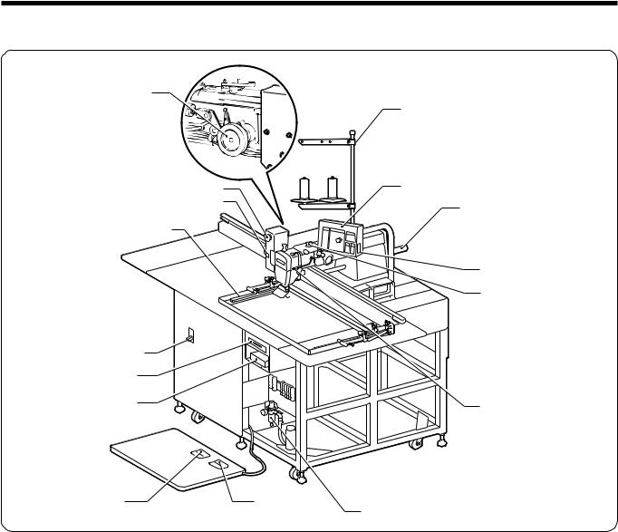
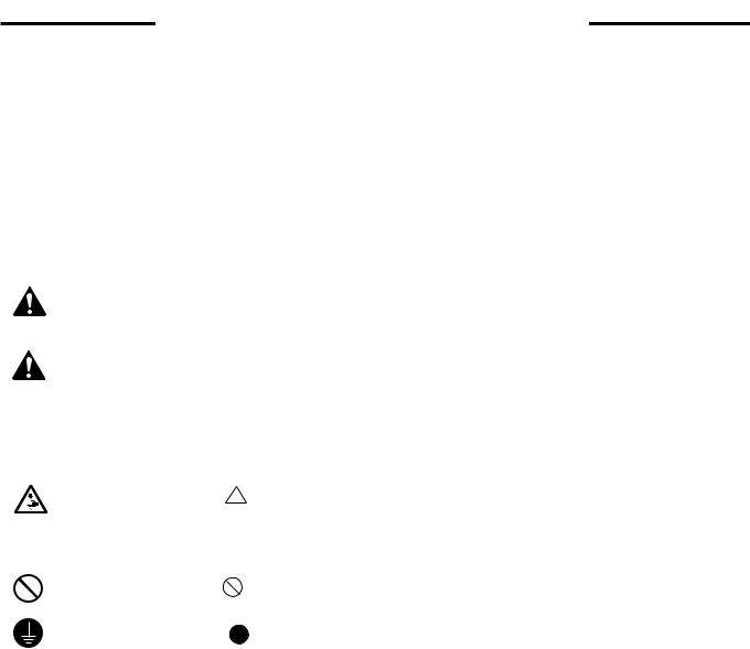
Chapter 1 NAME OF MAJOR PARTS
Chapter 1 NAME OF MAJOR PARTS
Hand Pully
Spool stand
Emergency stop switch |
Operation panel |
Reset switch |
Arm motor cover |
|
|
Work clamp |
|
|
Dip sw |
|
Bobbin winder |
Power switch |
|
Floppy disk drive |
|
Programmer |
Beam sensor-type |
|
|
|
needle thread breakage |
|
detector |
Work clamp lift switch |
Start switch |
Integrater
BAS-364E, 366E, 370E, 375E
1

Chapter 2 SPECIFICATIONS
Chapter 2 SPECIFICATIONS
Stitch type |
Single needle, lock stitch |
|
|
||||
|
|
|
|
||||
Sewing machine |
Lock stitch, double rotary hook, long arm machine |
|
|||||
|
|
|
|
|
|
|
|
Rotary hook |
Double rotary hook |
|
|
|
|
||
|
|
|
|
|
|
|
|
Needle |
|
|
DP 17, MR |
|
|
|
|
|
|
|
|
|
|
|
|
Stitch length |
0.05 - 12.7 mm |
|
|
|
|
||
|
|
|
|
|
|||
Max. sewing |
intermittent feed mode |
2,000 rpm (Max. stitch length 3 mm) |
|
|
|||
speed |
|
continuous feed mode |
3,200 rpm (Max. stitch length 3 mm) |
|
|
||
|
|
|
|
||||
|
|
|
|
|
|
||
|
|
|
420 400 mm ........... (BAS-364E) |
|
|
||
Max. pattern size |
650 400 mm ........... (BAS-366E) |
|
|
||||
|
(X - Y) |
800 400 mm ........... (BAS-370E) |
|
|
|||
|
|
|
|
|
|||
|
|
|
1,200 400 mm ........ (BAS-375E) |
|
|
||
|
|
|
|
|
|
||
Max. number of stitches |
20,000 stitches per pattern |
|
|
|
|||
|
|
|
|
|
|
|
|
Work clamp lift stroke |
Max. 50 mm |
|
|
|
|
||
|
|
|
|
|
|
|
|
Intermittent lift stroke |
16 mm |
|
|
|
|
||
|
|
|
|
||||
Test function |
Operation test function provided for use with low speed drive |
|
|||||
|
|
|
|
||||
Safety devices |
Automatic stop function for activation in the event of misoperation realized |
||||||
with intermediate stop |
function and safety circuits |
|
|||||
|
|
|
|
||||
|
|
|
|
|
|
|
|
|
|
|
W. 1,624 mm |
D. 1,100mm |
H. 1,868mm ...... |
(BAS-364E) |
|
Machine dimensions |
1,624mm |
|
1,557mm |
1,868mm ...... |
(BAS-366E) |
||
1,625mm |
|
1,820mm |
1,868mm ...... |
(BAS-370E) |
|||
|
|
|
|
||||
|
|
|
1,625mm |
|
2,620mm |
1,868mm ...... |
(BAS-375E) |
|
|
|
|
|
|||
Data storage method |
3.5 - floppy disc 2HD/ 1.44 MB, 2DD |
|
|
||||
|
|
|
|
|
|||
Power supply |
Three phase 220V, 380V, 400V 1KVA |
|
|
||||
|
|
|
|
|
|
|
|
Motor |
|
|
AC Servo motor 750W |
|
|
|
|
|
|
|
|
|
|
|
|
Air pressure |
0.5 MPa 1.8 l/ min |
|
|
|
|
||
|
|
|
|
|
|
|
|
Weights |
BAS-364E |
|
BAS-370E |
600kg |
|
||
400kg |
|
|
|
||||
|
|
|
BAS-366E |
|
BAS-375E |
|
|
|
|
|
|
|
|
|
|
BAS-364E, 366E, 370E, 375E
2
Chapter 3 INSTALLATION
Chapter 3 INSTALLATION
CAUTION
Machine installation should only be carried out by a qualified technician.
Contact your Brother dealer or a qualified electrician for any electrical work that may need to be done.
The sewing machine head weighs more than 65 kg. The installation should be carried out by two or more people.
Do not connect the power cord until installation is complete, otherwise the machine may operate if the foot switch is depressed by mistake, which could result in injury.
Be sure to connect the ground. If the ground connection is not secure, you run the risk of receiving a serious electric shock.
Be sure to wear protective goggles and gloves when handling the lubricating oil and grease, so that they do not get into your eyes or onto your skin, otherwise inflammation can result.
Furthermore, do not drink the oil or eat the grease under any circumstances, as they can cause vomiting and diarrhoea.
Keep the oil out of the reach of children.
Avoid setting up the sewing machine near sources of strong electrical noise such as highfrequency welding equipment.
If this precaution is not taken, incorrect machine operation may result.
1. Connecting the ground wire
 DANGER
Be sure to connect the gound. If the ground connection is not secure, you run the risk of receiving a serious electric shock.
Connection method for 3-phase power supply
Red |
3-phase |
|
White |
||
power supply |
||
Black |
||
|
Green/Yellow
....... Connect to ground
2. Positioning
Note
●Disconnect the power supply from the special socket afrer install has been completed.
●Be sure to connect the ground. If it is not connected, damage to the machine, incorrect operation and electric shocks may result.
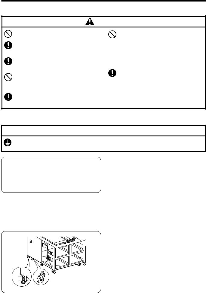
Decide the position for the sewing machine. Loosen nuts of six level adjusters q. Lower the level adjusters and secure them with nuts w. Turning the level adjuster counterclockwise will raise its height and turning it clockwise will lower it.
|
Note |
|
If the level adjusters are not secured properly, the |
w |
machine may move during operation, which could |
q |
result in injury or damage. |
|
BAS-364E, 366E, 370E, 375E
3
Chapter 3 INSTALLATION
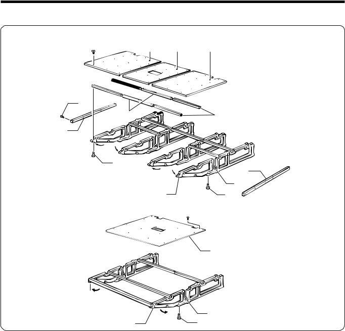
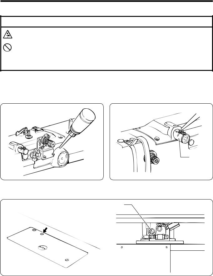
3. Installing the needle plates
* For BAS-370E, 375E
i o !0
r


u
r 


 r
r
i
t
w
* For BAS-364E, 366E
!1
q
y
q
e
we
1.Loosen the bolts q, and then pull the needle plate support bases w to the outside.
2.Secure the needle plate support bases w by tightening the bolts q and the bolts e.
3.Install the needle plate support brackets r to the needle plate support bases w by tightening the bolts t from below.
*For the BAS-366E and BAS-375E, install the needle plate support brackets y to the needle plate support brackets r with the bolts u.
4.Place the screw holes in the left needle plate i, center needle plate o and right needle plate !0on top of the needle plate support hases w so that the screw holes are aligned, and then secure them by tightening the screws.
*For the BAS-364E, install the center needle plate !1only.
BAS-364E, 366E, 370E, 375E
4
Chapter 3 INSTALLATION
4. Installing the work clamp hinge
|
y |
q |
|
|
u |
|
|
|
w |
|
|
|
|
|
|
|
|
i |
|
t |
r |
i |
|
|
w |
q |
|
|
|
||
|
|
|
y
e
u t
1.Clamp hinge spring (R) e and hinge spring (L) r with the work clamp arm q and work clamp hinge w.
2.After placing the thrust washer y onto Y pulley shaft (A) t, insert Y pulley shaft (A) t into the work clamp arm q and work clamp hinge w.
Note
Insert Y pulley shaft (A) t into the hole of the work clamp hinge w so that the screw stop u is facing upward.
3.Secure the work clamp hinge w and Y pulley shaft (A) t with the set screw i.
Note
Make sure that the set screw i goes into the screw stop u of Y pulley shaft (A) t.
5. Installing the arm motor cover
|
w |
r |
e |
|
|
|
|
|
|
t |
|
w
q |
r |
|
1.Move the feed mechanism q manually until it is as far into the machine as it will go.
(The ball spline w should be extended fully toward the front when looking from behind the arm.)
2.Aligh the arm motor cover e with the rear of the arm so that there is even clearance between the tube section r and the ball spline w, and then secure with the accessory screws t.
Note
If noise is heard from the tubular section r of the arm motor cover e while the machine is operating, adjust the installation position of the arm motor cover e according to the procedure in step 2. above.
BAS-364E, 366E, 370E, 375E
5
Chapter 3 INSTALLATION
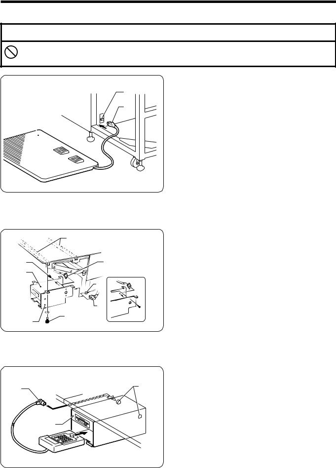
6. Installing the foot switch
 CAUTION
Do not connect the power cord until installation si compleate, otherwise the machine may operate if the foot switch is depressed by mistake, which could result in injury.
|
Be sure to attach the connector e of the foot switch w to |
|
q |
the connector q whose cord comes from the center of |
|
the front cover at the bottom of the machine. |
||
|
||
e |
|
w
7. Installing the programmer box
w |
1. |
Attach the programmer box q to the needle plate |
|
|
support w using the screws. |
||
|
|
||
|
2. |
Be sure to attach the two connectors r and t to the |
|
i |
u |
respective receptacles on the rear of the floppy disk |
|
drive y. |
|||
y |
|
||
3. |
Attach the connector u to the side of the programmer |
||
|
|||
r |
|
box q using the two screws i. |
t 
e
q


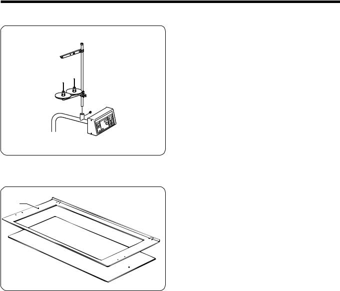
8.Installing the programmer
1.Insert the cord q of the programmer into the connector
|
|
w below the needle plate. |
q |
w |
2. The programmer can be placed inside the box e. |
|
|
|
|
e |
|
BAS-364E, 366E, 370E, 375E
6
Chapter 3 INSTALLATION
9. Installing the spool stand
Install the spool stand to the support of the panel.
10. Preparation of cassette
When not using the presser plate lower q, put the teflon
tape on the rear of the cassette w.
w
Note
If tape is not attached to the rear of the cassette, the top of the needle plate will become dirty, which could cause the material to become dirty.
 q
q
BAS-364E, 366E, 370E, 375E
7
Chapter 3 INSTALLATION
11. Lubrication
 CAUTION
Turn off the power switch before starting any cleaning work, otherwise the machine may operated if the foot switch is depressed by mistake, which could result in injury.
Be sure to wear protective goggles and gloves when handling the lubricating oil and grease, so that they do not get into your eyes or onto your skin, otherwise inflammation can result.
Furthermore, do not drink the oil or eat the grease under any circumstances, as they can cause vomiting and diarrhoea.
Keep the oil out of the reach of children.
Note
●Fill the machine with oil when the oil level is down to about one-third full in the oil sight glass. If oil is not added and the oil drops below this level, there is the danger that the machine may seize during operation.
●Be sure to let the machine operate for a while after adding the oil.
●Be sure to use Brother-specified machine oil (Nisseki Sewing Lub. 10).
q
1. Fill the oil tank with sewing machine oil. |
2. Fill the cooling tank q with silicon oil. |
B
A
3.Once or twice a week, fill the rotary hook lubrication tank B with machine oil from lubrication oil hole A until the tank is approximately two-thirds full. If more oil than this is added, oil may leak from the rotary hook.
BAS-364E, 366E, 370E, 375E
8
Chapter 3 INSTALLATION
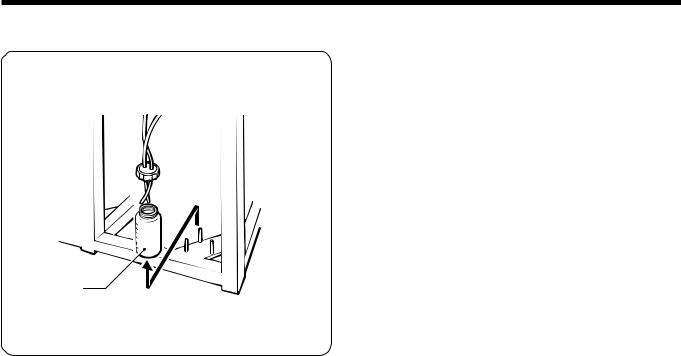
12. Draining oil
Remove and empty the waste oil tank q whenever it is full.
The waste oil tank q is underneath the front right leg.
q
BAS-364E, 366E, 370E, 375E
9
Chapter 3 INSTALLATION
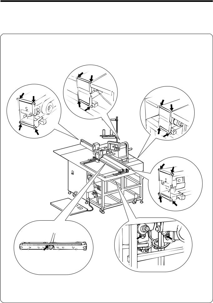
13. Applying grease
If the grease has run out, apply more grease in the places indicated by the arrows below.
Note
If you continue to operate the machine without any grease, it will cause abnormal noise and malfunctions to occur.
BAS-364E, 366E, 370E, 375E
10
Chapter 3 INSTALLATION
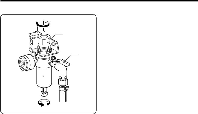
14.Adjusting the air pressure
1.Air pressure should be 0.5 MPa.
The air pressure can be adjusted by pulling up and turning the control knob w on the integrator q.
After adjustment is complete, push the control knob w w downward to lock it.
2. If water stands in the bottle of the integrator q, turn the drain cock e in the direction indicated by an arrow
r
to drain the water.
Note
Open the air cock r slowly.
q
e
BAS-364E, 366E, 370E, 375E
11
Chapter 4 CORRECT OPERATION
Chapter 4 CORRECT OPERATION
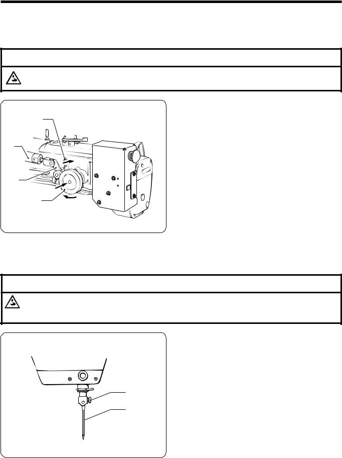
1. Turning the pulley by hand
 CAUTION
If the power switch and air need to be left on when carrying out some adjustment, be extremely careful to observe all safety precautions.
|
After pressing the hand pulley q in, it can then be turned |
|
w |
by hand. To return the hand pulley q, pull the lever w |
|
toward you. |
||
|
* Furthermore, the hand pulley qwill automatically return |
|
|
to its original position at the sewing start and when the |
|
r |
work clamp is raised and lowered. |
|
|
Note |
|
|
Do not touch the hand pulley q, lever w, work clamp |
|
e |
lifter arm e or cylinder r while the machine is |
|
operating and when the work clamp is being raised |
||
|
||
|
and lowered, otherwise injury may result. |
|
q |
|
2. Installing the needle
 CAUTION
Turn off the power switch at the following times, otherwise the machine may operate if the start switch is pressed by mistake, which could result in injury.
● When replacing the needle
Loosen set screw q. Fully insert the needle w with the groove facing the front, and then retighten set screw q.
Note |
|
● |
Always make sure that the needle w is fully inserted |
|
facing the front. |
● |
If the needle is installed incorrectly, problems such |
q |
as needle breakage may occur. |
|
|
w |
|
BAS-364E, 366E, 370E, 375E
12
Chapter 4 CORRECT OPERATION
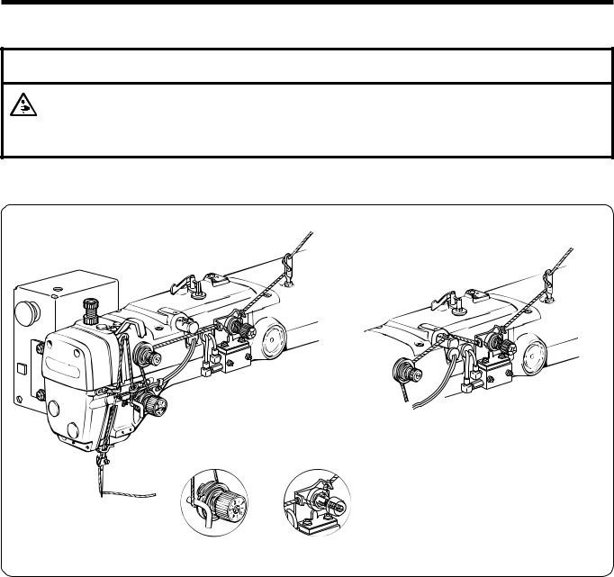
3. Threading the upper thread
 CAUTION
If the power switch needs to be left on when carrying out threading, be extremely careful to observe all safety precautions.
The machine may operate if the foot switch is depressed by mistake, which could result in injury. (ex. Continuing sewing from a stopping point)
Thread the upper thread as shown in the diagrams below.
<With cotton thread> |
<With synthetic thread> |
|
0 |
|
1 |
4 |
|
3 |
||
2 |
|
0 |
|
1 |
4 |
|
3 |
||
2 |
Hole inclination 45˚
BAS-364E, 366E, 370E, 375E
13
Chapter 4 CORRECT OPERATION
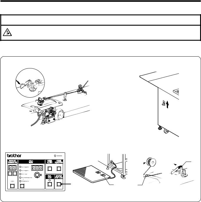
4. Winding the lower thread
 CAUTION
Do not touch any of the moving parts or press any objects against the machine while the bobbin is turning, as this may result in personal injury or damage to the machine.
Note
Do not touch the bobbin or the bobbin holder while the bobbin is turning, otherwise injury may result.
 q
q
0 |
4 |
1 |
3 |
2 |
w


 series
y
q


e |
r |
t |
1.Slide the bobbin all the way onto the spindle.
2.Thread the thread as shown in the illustration (in the case of the BAS-364E and 366E, there is no lower thread guide u), wind the thread around the bobbin several time in the direction shown by the arrow, and then press the bobbin presser q.
3.Turn the power switch w on.
● |
The power indicator on the operation panel will light. |
4. |
Press and hold the STEP BACK switch e on the operation panel, and depress the start switch r to start the |
|
sewing machine. |
● |
Keep the start switch depressed until the bobbin is fully wound. |
● |
Release the STEP BACK switch e when the sewing machine starts. |
5.The bobbin holder q will automatically return when the bobbin is filled to capacity (approximately 80 - 90 % of the bobbin diameter).
6.Release the start switch r.
7.Remove the bobbin, and pull the bobbin in the direction of the arrow to cut the thread on the thread cutter t.
8.To wind more thread onto the bobbin, loosen the set screw y and move the bobbin holder q out in the direction of the arrow.
BAS-364E, 366E, 370E, 375E
14
Chapter 4 CORRECT OPERATION
Note
If the bobbin thread is wound unevenly onto the bobbin, loosen nut q, and turn thread tension stud w to adjust so that the thread is wound evenly. If the bobbin is wound as in Fig. A, turn the stud clockwise, if Fig. B,
w |
turn the stud counterclockwise. |
|
|
|
A |
q
B
5. Installing the bobbin case
 CAUTION
If the power switch needs to be left on when carrying out replacing the bobbin, be extremely careful to observe all safety precautions.
The machine may operate if the foot switch is depressed by mistake, which could result in injury. (ex. Continuing sewing from a stopping point)
Note
●Do not replace the bobbin or put your hand close to the bobbin case while the machine is operating.
●Do not operate the machine while replacing the bobbin, otherwise injury and damage could result.
r
t
e
q
w
1.Raise the bobbin case latch w, and then remove the bobbin case q from inside the rotary hook at the front of the machine head.
2.While the bobbin case latch w is still lowered, remove the bobbin e from the bobbin case q.
3.Place a new bobbin with the bobbin thread already wound on into the bobbin case q, and then pass the thread through the slot r and pull it out from the thread hole t.
BAS-364E, 366E, 370E, 375E
15
Loading...