

Page 1

Stamp Creator PRO
SERVICE MANUAL
MODEL: SC-2000 Version A
Page 2

Stamp Creator PRO
SERVICE MANUAL
MODEL: SC-2000
Page 3

Copyright Brother 1999
All rights reserved.
No part of this publication may be reproduced in any
form or by any means without permission in writing from
the publisher.
Specifications are subject to change without notice.
Page 4

Stamp Creator PRO SC-2000
Mechanical Part
CONTENTS
CHAPTER I SPECIFICATIONS...................................................................................I-1
1. MECHANICAL SPECIFICATIONS................................................................................................I-1
1.1 Overview.........................................................................................................................I-1
1.2 Input Specifications.........................................................................................................I-2
1.3 Display Specifications......................................................................................................I-2
1.4 Printing Specifications.....................................................................................................I-2
1.5 Engraving Stamp Specifications.......................................................................................I-3
1.6 Xenon Unit Specifications................................................................................................I-3
1.7 Ribbon Cassette Specifications........................................................................................I-3
1.8 Magazine Tray Specifications..........................................................................................I-3
1.9 Stamp Specifications.......................................................................................................I-4
1.10 Draft Sheet Specifications................................................................................................I-6
1.11 ID Label Specifications....................................................................................................I-6
CHAPTER II THEORY OF MECHANISM OPERATION.............................................II-1
1. PRINTING MECHANISM.............................................................................................................II-1
1.1 Construction of Thermal Head........................................................................................II-1
1.2 Theory of Printing...........................................................................................................II-1
1.3 Configuration of Character and Graphics........................................................................II-1
2. ENGRAVING STAMP MECHANISM............................................................................................II-2
2.1 Theory of Engraving Stamp............................................................................................II-2
2.2 Positioning the Holder.....................................................................................................II-3
3. FEEDING MECHANISM..............................................................................................................II-4
3.1 Feeding Draft Sheet.......................................................................................................II-4
3.2 Feeding Draft Sheet and ID Label...................................................................................II-5
1
Page 5

CHAPTER III DISASSEMBLY AND REASSEMBLY.................................................III-1
1. DISASSEMBLING PROCEDURES.............................................................................................III-2
1.1 Disassembly of the I/F Cable and the AC Cord..............................................................III-2
1.2 Disassembly of the Magazine Tray Assy and the Xenon Unit.........................................III-3
1.3 Disassembly of the Ribbon Cassette Assy.....................................................................III-4
1.4 Disassembly of the Main PCB Assy...............................................................................III-5
1.5 Disassembly of the Capacitor Case...............................................................................III-7
1.6 Disassembly of the Body Cover.....................................................................................III-9
1.7 Disassembly of the Main Chassis and the Bottom Cover.............................................III-12
1.8 Disassembly of the Power Supply PCB Assy...............................................................III-15
1.9 Disassembly of the Thermal Head Unit........................................................................III-16
1.10 Disassembly of the Sensor Assys................................................................................III-17
1.11 Disassembly of the Micro Switches..............................................................................III-18
1.12 Disassembly of the Platen Unit Assy............................................................................III-19
1.13 Disassembly of the Presser Unit Assy.........................................................................III-21
1.14 Disassembly of the Head Holder Assy.........................................................................III-26
1.15 Disassembly of the Gears and Pulleys.........................................................................III-28
1.16 Disassembly of the Motor Holder Assy and the Motors................................................III-29
1.17 Disassembly of the Rollers..........................................................................................III-30
1.18 Disassembly of the Label Guide Assy..........................................................................III-31
1.19 Disassembly of the Film Path Assy..............................................................................III-33
1.20 Disassembly of the Drawer Connector.........................................................................III-35
2. REASSEMBLING PROCEDURES............................................................................................III-36
2.1 Reassembly of the Drawer Connector..........................................................................III-36
2.2 Reassembly of the Film Path Assy..............................................................................III-37
2.3 Reassembly of the Label Guide Assy...........................................................................III-42
2.4 Reassembly of the Rollers...........................................................................................III-45
2.5 Reassembly of the Motor Holder Assy and the Motors.................................................III-48
2.6 Reassembly of the Gears and Pulleys.........................................................................III-49
2.7 Reassembly of the Head Holder Assy..........................................................................III-51
2.8 Reassembly of the Presser Unit Assy..........................................................................III-54
2.9 Reassembly of the Platen Unit Assy............................................................................III-61
2.10 Reassembly of the Micro Switches..............................................................................III-63
2.11 Reassembly of the Sensor Assys................................................................................III-64
2.12 Reassembly of the Thermal Head Unit.........................................................................III-65
2.13 Reassembly of the Power Supply PCB Assy................................................................III-66
2.14 Reassembly of the Bottom Cover and the Main Chassis..............................................III-67
2.15 Reassembly of the Body Cover....................................................................................III-69
2.16 Reassembly of the Capacitor Case..............................................................................III-72
2.17 Reassembly of the Main PCB Assy..............................................................................III-74
2
Page 6

2.18 Reassembly of the Ribbon Cassette Assy....................................................................III-77
2.19 Reassembly of the Xenon Unit.....................................................................................III-78
2.20 Reassembly of the Magazine Tray Assy......................................................................III-79
2.21 Reassembly of the AC Cord and the I/F Cable.............................................................III-79
2.22 Lubrication during Reassembly....................................................................................III-80
CHAPTER IV TROUBLESHOOTING........................................................................IV-1
1. GENERALS................................................................................................................................IV-1
2. PRECAUTIONS ON REPAIRING................................................................................................IV-1
3. ACTIONS TO BE TAKEN AFTER REPAIRS...............................................................................IV-1
3
Page 7
CHAPTER I SPECIFICATIONS
1. MECHANICAL SPECIFICATIONS
1.1 Overview
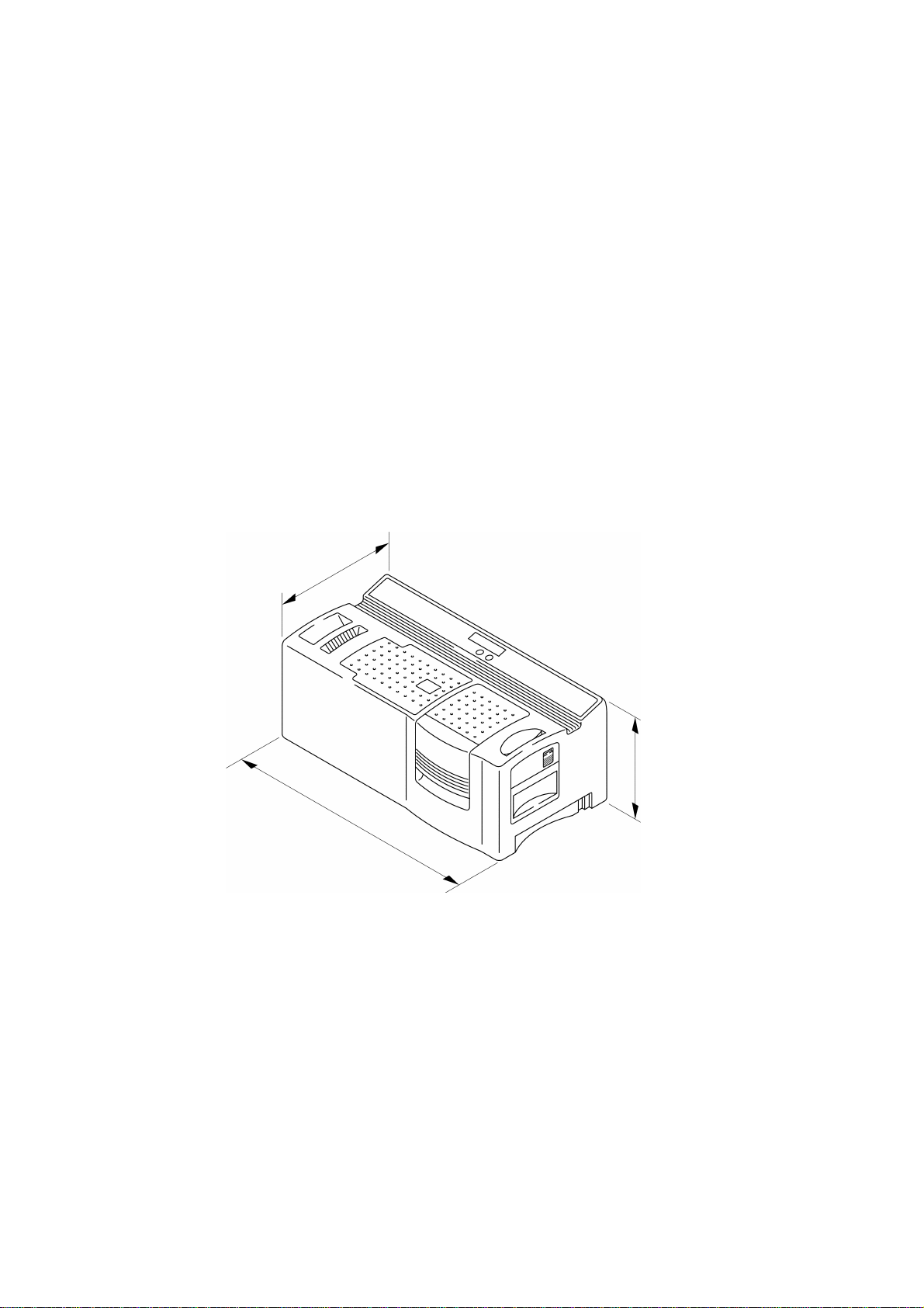
(1) External view See Fig. 1.1.
(2) Dimensions 470 mm (W) × 238.3 mm (D) × 180.8 mm (H)
(without the magazine tray assy)
(3) Weight Approx. 8 kg
(4) Total weight Approx. 11 kg
(machine and package)
238.3 mm
180.8 mm
470 mm
Fig. 1.1 External Dimensions
I - 1
Page 8
1.2 Input Specifications
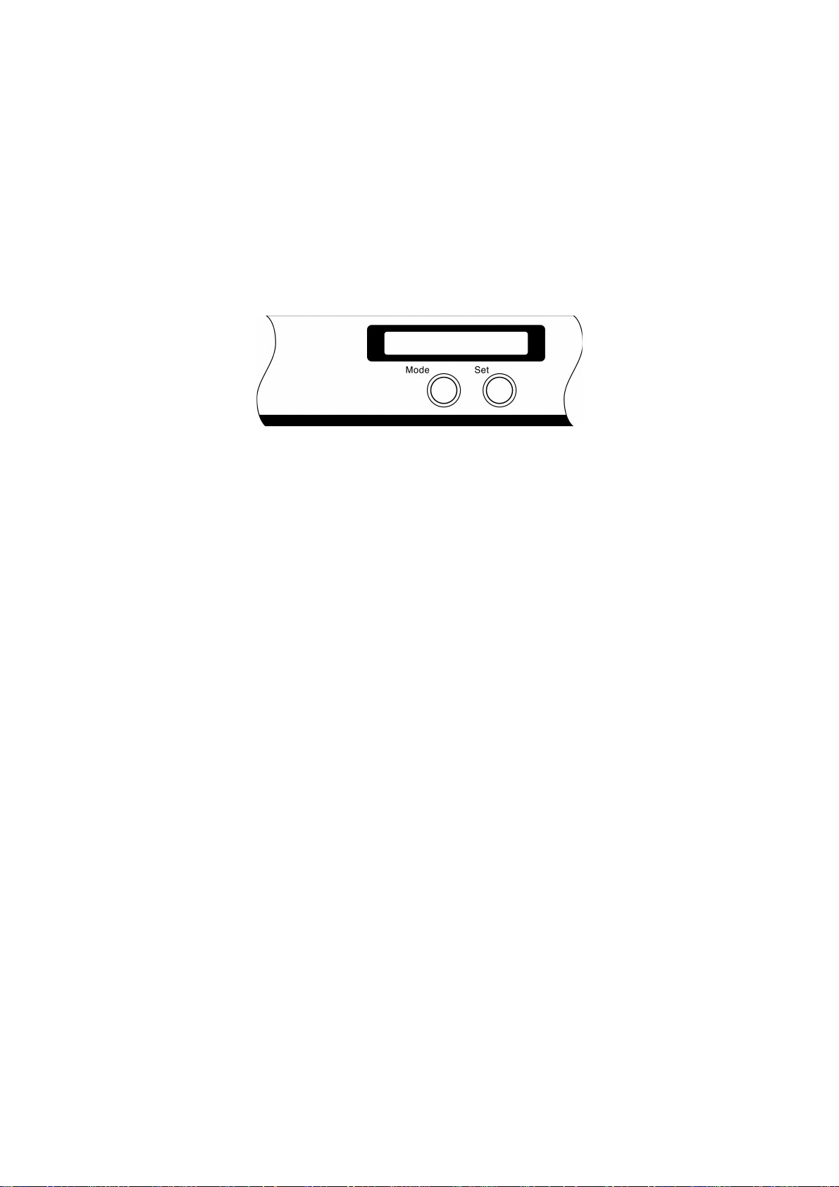
(1) Type of keys Tactile switch
(2) Number of keys 2
(3) Key layout See Fig. 1.2
1.3 Display Specifications
(1) Display method Character type LCD
Fig. 1.2 Control Panel
(2) Number of characters 15 columns × 1 line
(3) Dots CG construction 5 dots × 7 dots + the cursor
(4) Dot size 0.58 mm wide by 0.524 mm high
(5) Dot pitch 0.65 mm wide by 0.594 mm high
1.4 Printing Specifications
(1) Printing type Thermal fusion and printing method by
(2) Printing speed 99.2 dots/sec. (4.2 mm/sec.)
(3) Thermal head construction Thin film thermal head 960 dots × 1 dot
thermal head
Vertical pitch 0.0425 mm (1/600 inch)
Dimensions of a heating element
0.035 mm wide by
0.060 mm high
I - 2
Page 9

1.5 Engraving Stamp Specifications
(1) Engraving stamp method Light engraving stamp method
(2) Operation load 98 N (10 kgf) or lower
(3) Light source Xenon lamp (xenon unit)
1.6 Xenon Unit Specifications
(1) Light source Xenon lamp
(2) Light emission times 2000 times or more
(3) Construction Xenon tube, reflector, acrylic plate, and glass
(4) Packaged standard xenon unit Yes (1 piece)
1.7 Ribbon Cassette Specifications
(1) Ink color Black
plate
(2) Printing times 150 or more printing surfaces
(3) Packaged standard ink Yes (1 piece)
ribbon cassette
1.8 Magazine Tray Specifications
(1) Capacity 50 draft sheets
(2) Separation method Separation method by claws
(3) Packaged standard Yes (1 piece)
magazine tray
(1 printing surface includes both an ID label
and a draft sheet.)
I - 3
Page 10
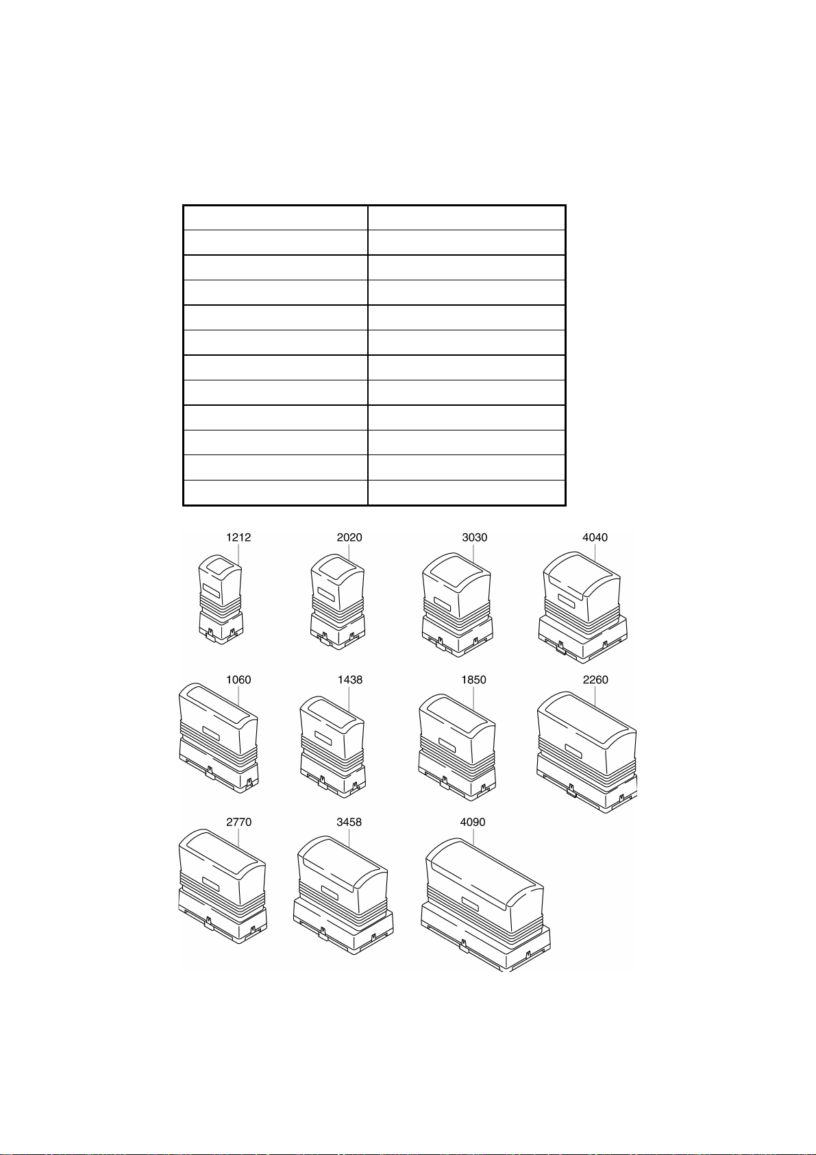
1.9 Stamp Specifications
(1) Types and sizes of stamp
Size Dimensions (mm)
1212
2020
3030
4040
1060
1438
1850
2260
2770
3458
4090
28 × 31
36 × 39
47 × 50
57 × 60
26 × 79
30 × 57
34 × 69
38 × 79
43 × 90
51 × 78
57 × 110
Fig. 1.3 Stamp Types
I - 4
Page 11
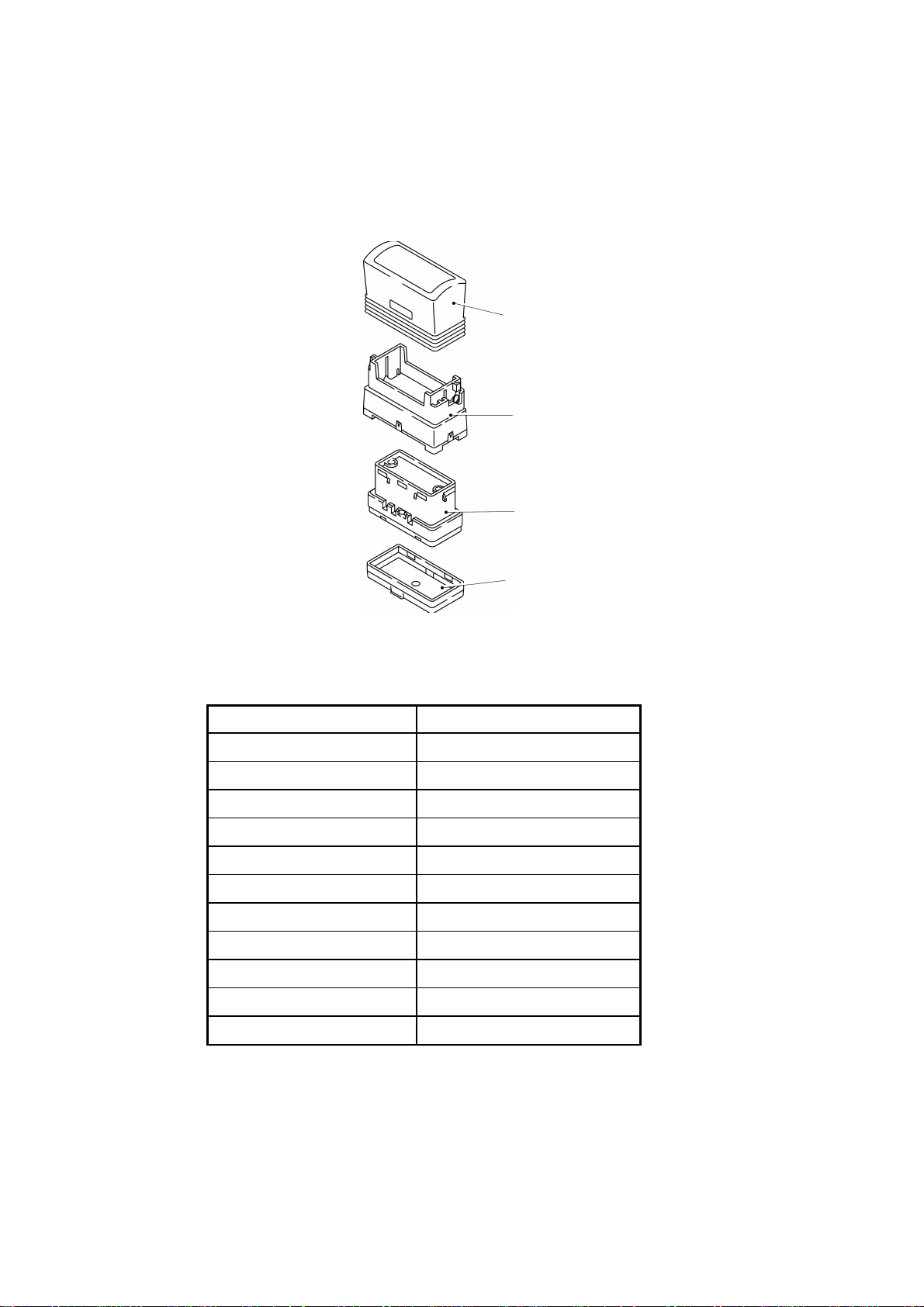
(2) Configuration Grip, skirt, holder, and cap
(The holder consists of printing material,
an absorption sheet, an ink pack, and an
inside plate.)
Grip
Skirt
Holder
Cap
Fig. 1.4 Stamp Configuration
(3) Effective printing area
Size Dimensions (mm)
1212
2020
3030
4040
1060
1438
1850
2260
2770
3458
4090
9.9 × 9.8
18.0 × 18.0
27.2 × 27.1
37.4 × 37.3
7.8 × 57.9
11.9 × 36.2
16.0 × 47.8
19.0 × 56.9
23.8 × 67.1
31.3 × 54.9
37.4 × 86.7
(4) Ink color (for each size) Black, red, and blue
(5) Packaged standard stamp Yes (1438 and 1850: 2 pieces,
2770: 1 piece)
I - 5
Page 12
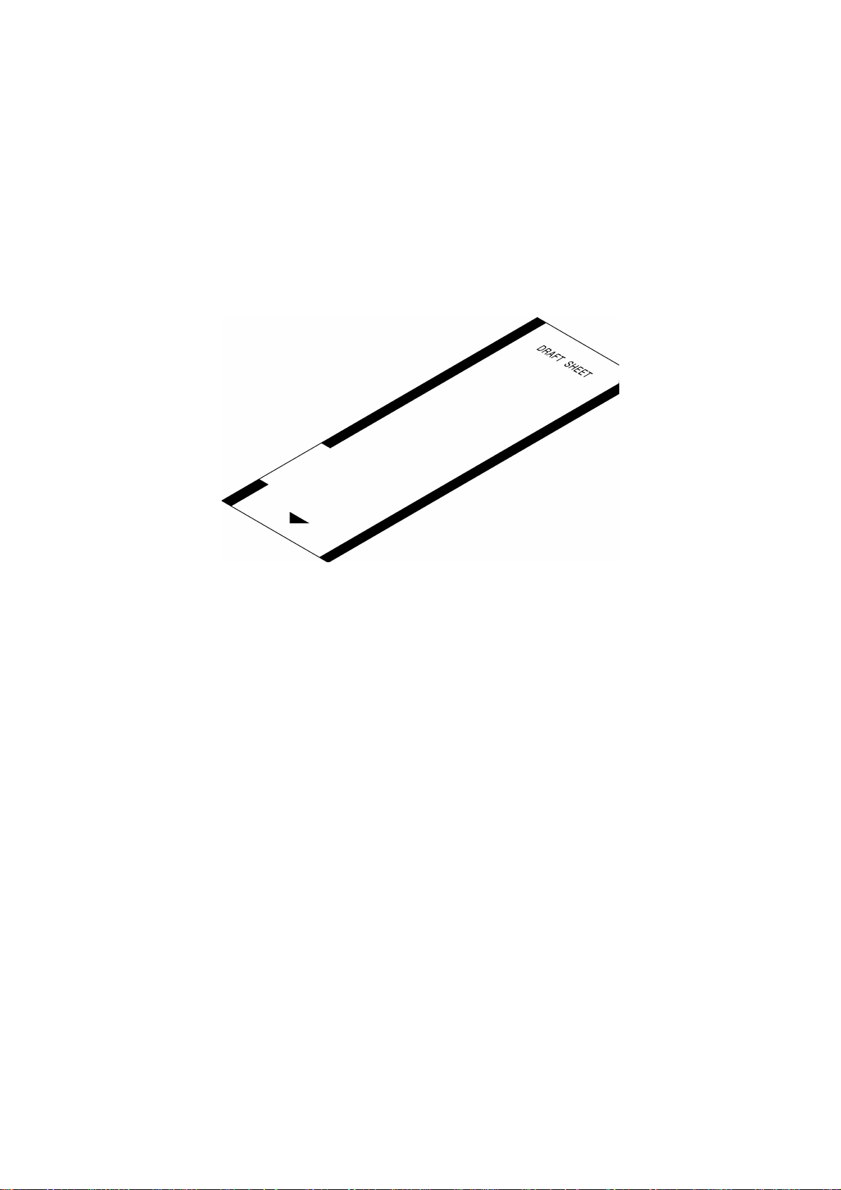
1.10 Draft Sheet Specifications
(1) Dimensions 58 mm × 172 mm × 0.1 mm
(2) Material PET film
(3) Packaged standard draft sheet Yes (150 sheets)
1.11 ID Label Specifications
(1) Dimensions 58 mm × 170 mm × 0.15 mm
(2) Material White PET film
(3) Type A total of 11 types (1212, 2020, 3030, 4040,
(4) Packaged standard ID label Yes (1438 and 1850: 2 labels,
Fig. 1.5 Draft Sheet
(with adhesive and a separator on the back)
1060, 1438, 1850, 2260, 2770, 3458, and
4090)
2770: 1 label)
I - 6
Page 13
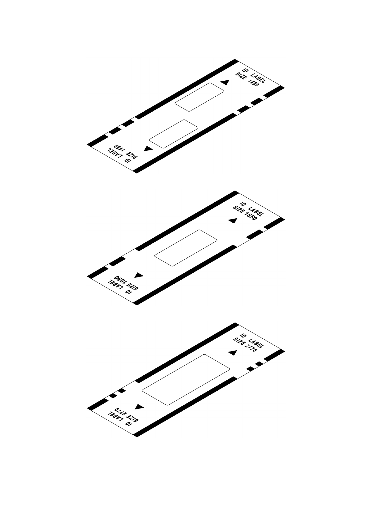
Fig. 1.6 ID Label 1438
Fig. 1.7 ID Label 1850
Fig. 1.8 ID Label 2770
I - 7
Page 14
CHAPTER IITHEORY OF MECHANISM OPERATION
1. PRINTING MECHANISM
1.1 Construction of Thermal Head
The thermal head contains 960 heating elements vertically arranged. The size of
one heating element is 0.035 mm wide by 0.060 mm high, as shown in Fig. 2.1.
0.0425 mm
40.7925 mm
0.035 mm
0.060 mm
Fig. 2.1 Heating Elements of the Thermal Head
1.2 Theory of Printing
During printing operation, the thermal head crimps the ink ribbon and a draft sheet
(or an ID label) on the cylindrical rubber platen. In this state, the CPU selects the
required heating elements out of the 960 heating elements to energize them. When
the energized heating elements are heated, the ink in the ink ribbon is fused, and
the ink is transferred to an adhered draft sheet (or an ID label) to print dots. The ink
ribbon and the draft sheet (or the ID label) are fed to the next printing position
simultaneously at the same speed to start the next printing cycle. By repeating the
printing cycles in this manner, a character and graphics is printed on the surface of
a draft sheet (or an ID label).
1.3 Configuration of Character and Graphics
The driving motor continuously feeds a draft sheet (or an ID label) and the ink
ribbon by 0.0423 mm in 9 ms, during which the CPU heats the thermal head once to
print a character and graphics.
II - 1
Page 15
2. ENGRAVING STAMP MECHANISM
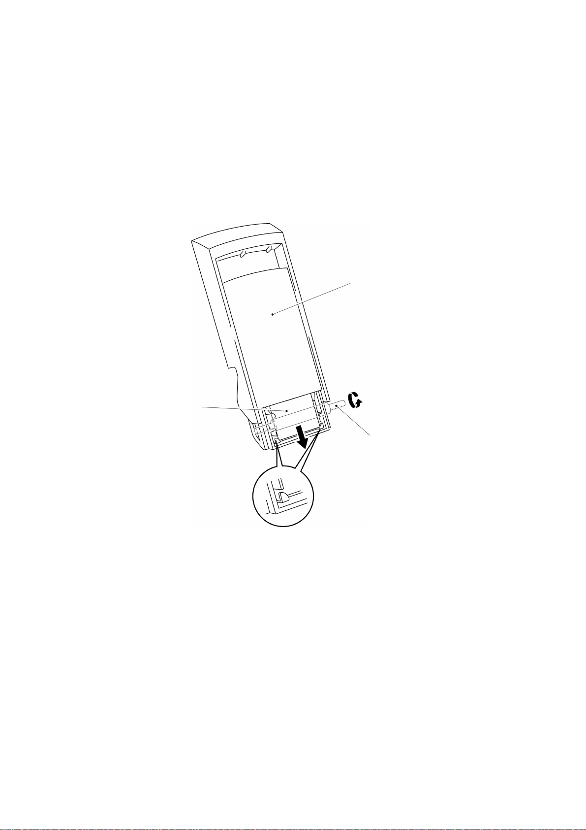
2.1 Theory of Engraving Stamp
The draft sheet printed with a character and graphics is fed onto the transparent
plate on the light emitting part of the xenon unit. Position the holder on the draft
sheet with the printing material (made of porous resin) facing down, and apply a
load on the holder by closing the engraving stamp cover to cause the xenon lamp to
emit light. As for the draft sheet's area printed with no character or graphics, the
light is directly irradiated on the printing surface. The light heats the carbon
contained in the printing material to thermally fuse the printing material, and the
pressure closes up the holes in the printing material. This manufactures the printing
surface with holes left only on the area with a character and graphics. After
engraving stamp, setting the grip on the holder fills the inside of the holder with the
ink from the ink pack to enable imprinting.
Draft sheet
Stamp holder
Xenon lamp
Fig. 2.2 Stamp Holder Mounting
II - 2
Page 16

2.2 Positioning the Holder
The holder is positioned at the engraving stamp position by the two interlocked
shutters that open and close back and forth and the triangular projections in the
centers of the shutters. At this time, the six micro switches send ON/OFF signals
according to the shapes of the hollows in the holder, which depend on the size of
the holder, to detect the size of the holder, as shown in Fig. 2.3.
Shutter rear
Shutter front
Holder
Triangular hollow in the
holder
Triangular projection of the shutter
Note: The above shows holder 1850.
Holder
Micro switch
(for stamp size detection)
Fig. 2.3
Holder
II - 3
Page 17
3. FEED MECHANISM
3.1 Feeding Draft Sheet
The draft sheets, set in the magazine tray assy, are fed one by one from the side
contacting the paper feed roller, and then separated by the separating claws, as
shown in Fig. 2.4.
Magazine tray assy
Draft sheet
Paper feed roller
Separating claws
Fig. 2.4
II - 4
Page 18
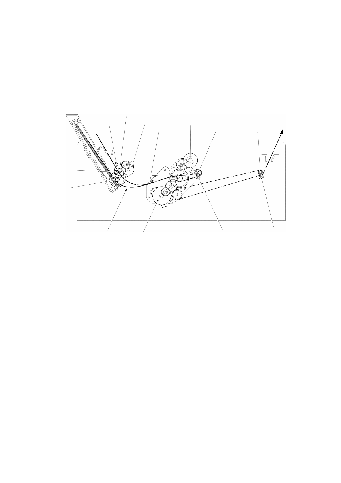
3.2 Feeding Draft Sheet and ID Label
The driving motor rotates each roller via a gear train and the timing belt (MXL belt)
to feed a draft sheet and an ID label, as shown in Fig. 2.5. The feeding position of
the draft sheet is detected by the transparent sensors to control the printing start
position and the engraving stamp position.
Paper feed roller
Reflective sensor
Nip roller
Paper feed
roller
Paper feed motor
Reflective sensor
Transparent sensor
Paper eject rollerDriving roller
Draft sheet
Main motor
Nip roller
Eject roller shaft
(Xenon unit assy)
Fig. 2.5 Feeding Path
II - 5
Page 19

CHAPTER III DISASSEMBLY AND REASSEMBLY
Precautions on Safety
(1) Disassemble and reassemble the machine on a grounded antistatic sheet.
Touching electronic components such as an LSI with an electrified hand will
break them, as they are easily affected by static electricity.
(2) Wrap the machine in an electrically conductive aluminum sheet before carrying
it.
(3) When using heating tools such as soldering iron, take care not to thermally
break resin components such as a wire, a PCB, and a cover.
(4) Take care not to lose small components, such as a screw and a washer, which
have been removed to replace other components.
(5) Never remove main capacitor charge PCB from the capacitor case since
the PCB may be charged with high voltage.
List of Tightening Torque
Position Screw Qty. Tightening torque
N·cm (kgf·cm)
Paper feed motor
Main motor
Motor holder sub assy
Presser unit assy Screw, pan
Presser unit assy
(front: shutter cover)
Thermal head unit
Main chassis
Control panel PCB
holder
Body cover (rear)
Body cover (top)
Main capacitor unit
assy
Screw, bind M2.6 × 5
Screw, bind M3 × 5
Screw, bind M3 × 5
(S/P washer) M3 × 6DB
Screw, pan
(S/P washer) M3 × 6DB
Screw, bind M3 × 5
Taptite, bind B M3 × 12
Taptite, bind B M3 × 12
Screw, bind B M3 × 12
Screw, bind M3 × 5
Screw, bind M3 × 8
Screw, bind B M3 × 12
2
2
3
12
2
2
6
2
3
1
2
4
49 ± 9.8 (5 ± 1)
58.8 ± 9.8 (6 ± 1)
58.8 ± 9.8 (6 ± 1)
117.6 ± 9.8 (12 ± 1)
117.6 ± 9.8 (12 ± 1)
58.8 ± 9.8 (6 ± 1)
78.4 ± 9.8 (8 ± 1)
78.4 ± 9.8 (8 ± 1)
78.4 ± 9.8 (8 ± 1)
58.8 ± 9.8 (6 ± 1)
58.8 ± 9.8 (6 ± 1)
78.4 ± 9.8 (8 ± 1)
III - 1
Page 20
1. DISASSEMBLY PROCEDURES
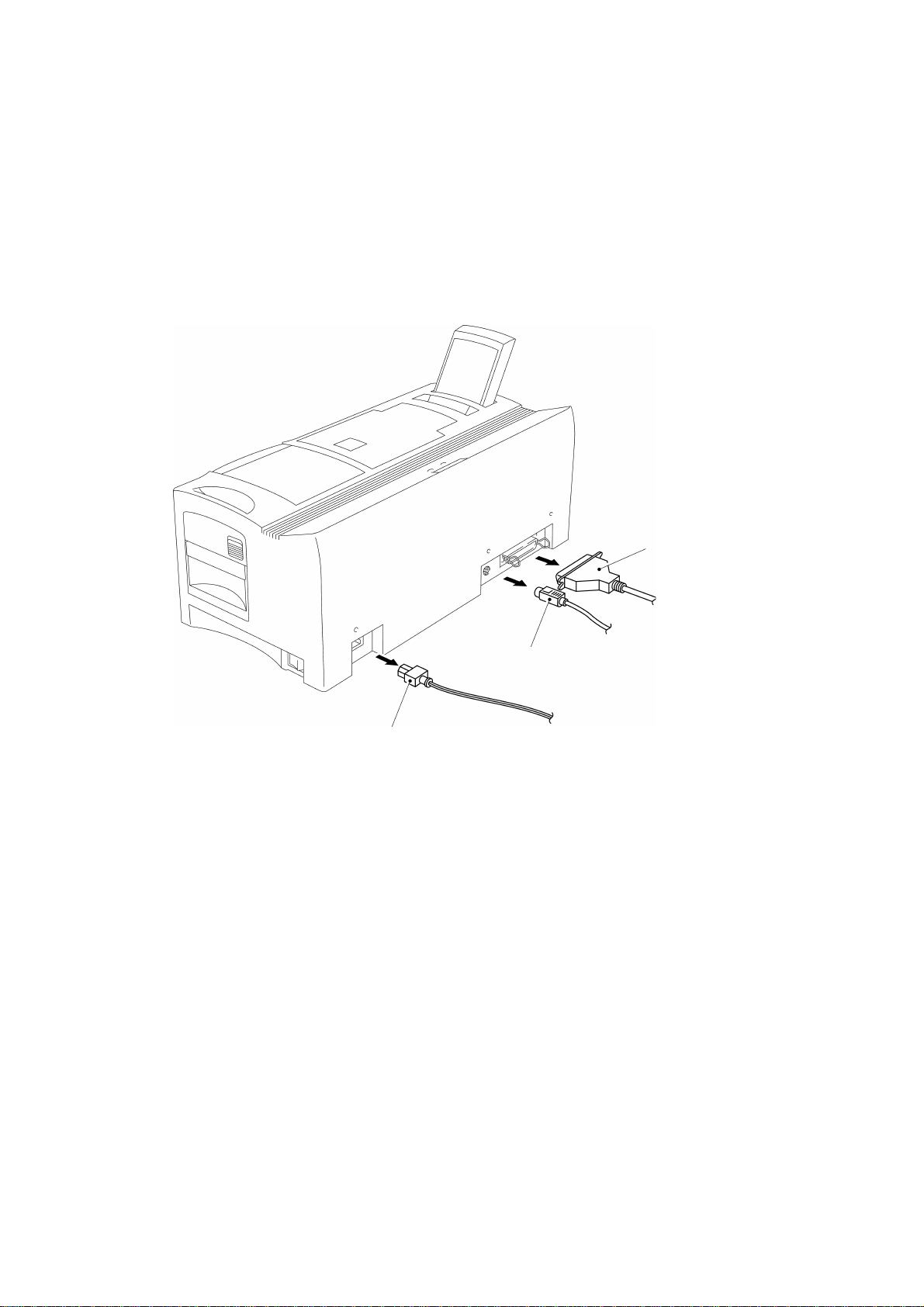
1.1 Disassembly of the I/F Cable and the AC Cord
Remove the I/F cable and the AC cord in the back of the machine, as shown in Fig.
3.1.
Parallel I/F cable
Serial I/F cable
AC cord
Fig. 3.1
III - 2
Page 21
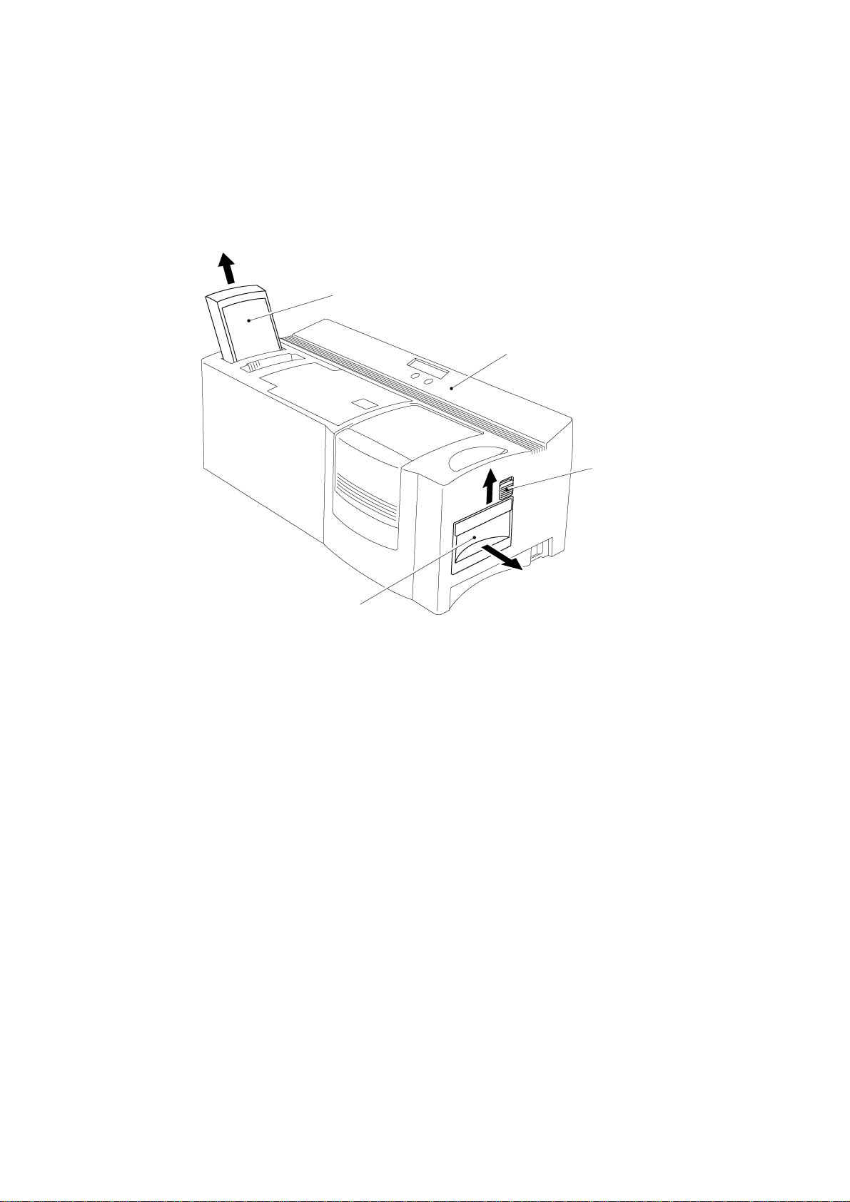
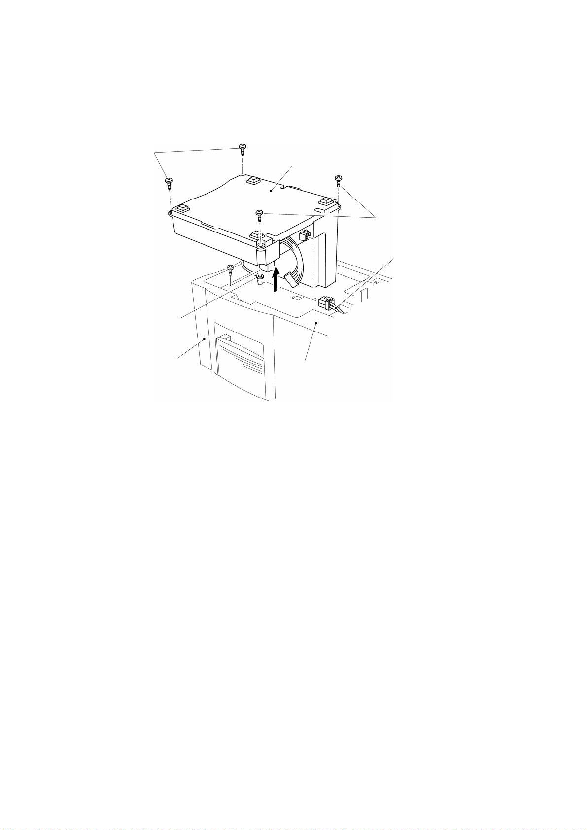
1.2 Disassembly of the Magazine Tray Assy and the Xenon Unit
Remove the magazine tray assy by lifting it diagonally.
While sliding the slide lever on the side of the machine upwards, pull out the xenon
unit, as shown in Fig. 3.2.
Magazine tray assy
Body cover
Slide lever
Xenon unit
Fig. 3.2
III - 3
Page 22
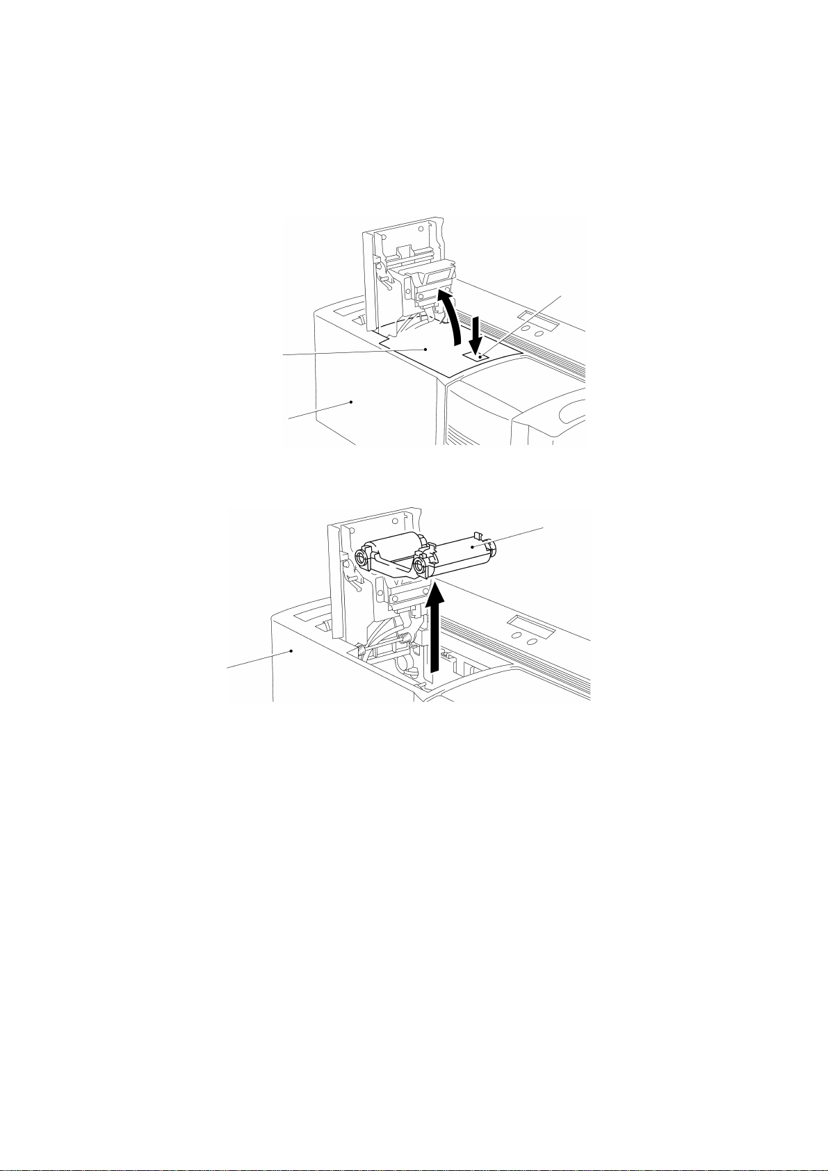
1.3 Disassembly of the Ribbon Cassette Assy
Press the open button on top of the machine to open the cassette cover, and
remove the ribbon cassette assy, as shown in Figs. 3.3 and 3.4.
Cassette cover
Body cover
Fig. 3.3
Open button
Ribbon cassette assy
Body cover
Fig. 3.4
III - 4
Page 23
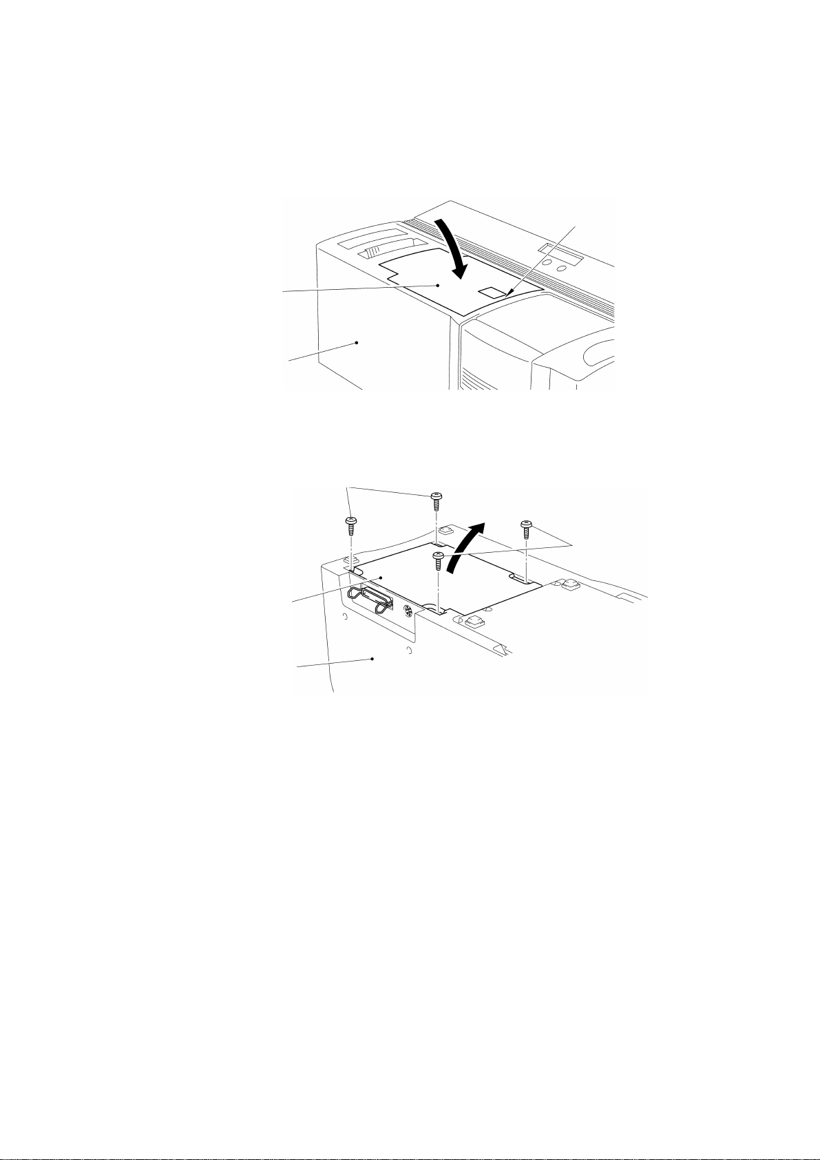
1.4 Disassembly of the Main PCB Assy
Press part A of the cassette cover to close it, as shown in Fig. 3.5.
Cassette cover
Body cover
Fig. 3.5
Turn the machine over and remove the four screws to remove the main PCB assy,
as shown in Fig. 3.6.
Screws
A
Screws
Main PCB bottom plate
Body cover
Fig. 3.6
III - 5
Page 24
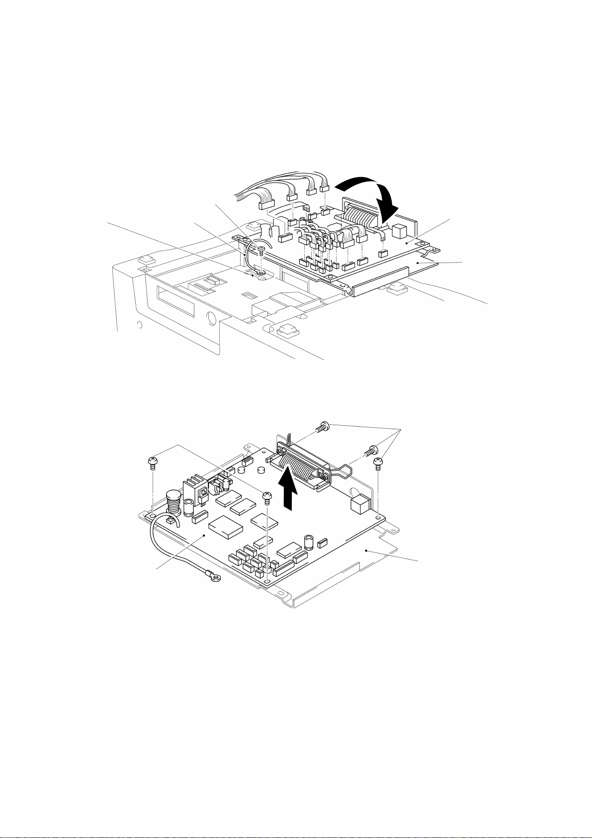
Pull out the connectors from the main PCB assy.
Remove the screw to remove the ground wire from the main chassis, as shown in
Fig. 3.7.
Note: Put on a static control wrist band before handling PCBs.
Screw
Ground wireMain chassis
Fig. 3.7
Main PCB assy
Main PCB
bottom plate
Remove the five screws to remove the main PCB assy from the main PCB bottom
plate, as shown in Fig. 3.8.
Screws
Screws
Main PCB
Main PCB assy
Fig. 3.8
bottom plate
III - 6
Page 25
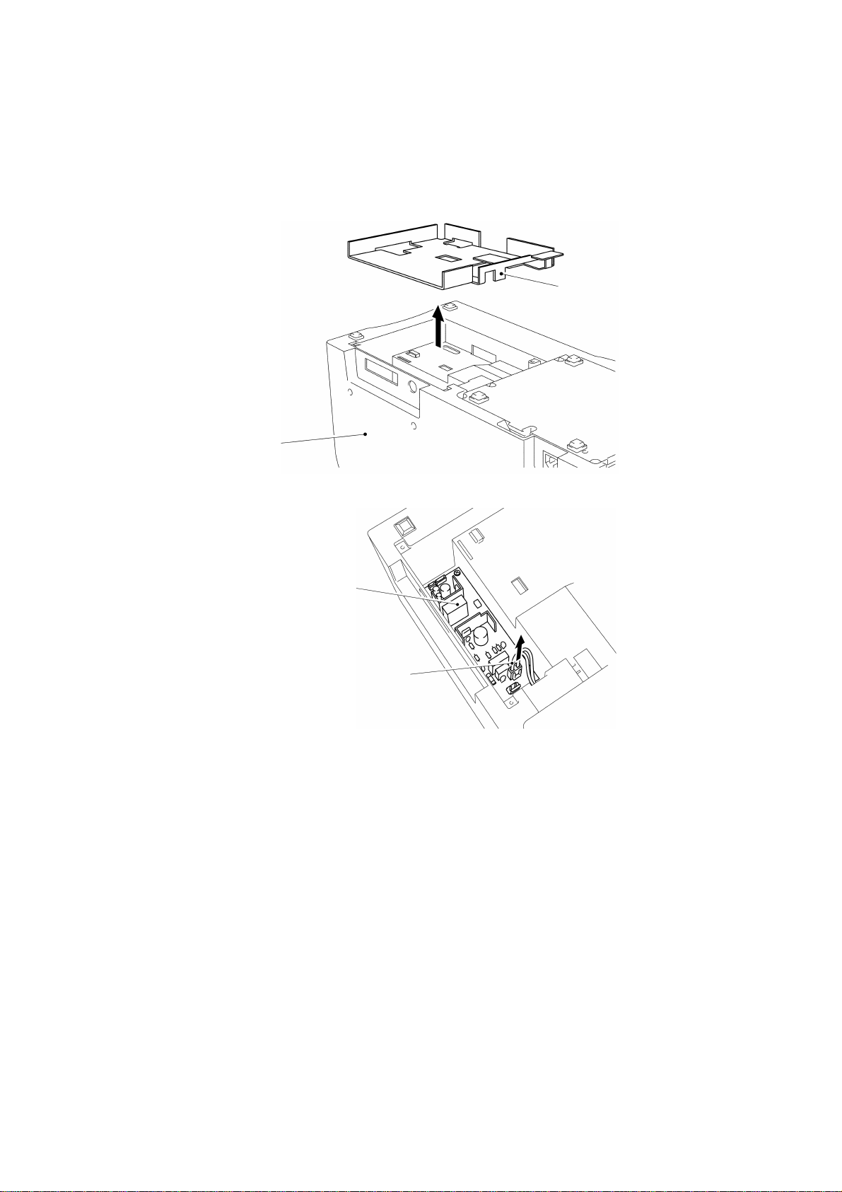
1.5 Disassembly of the Capacitor Case
Remove the shield plate and pull out the connector of the power supply harness
from the power supply PCB assy, as shown in Fig. 3.9.
Body cover
Shield plate
Power supply PCB assy
Power supply harness
Fig. 3.9
III - 7
Page 26
Remove the four screws to remove the capacitor case from the bottom cover.
Remove the capacitor harness from the connector of the capacitor case, and
remove the screw to remove the ground wire, as shown in Fig. 3.10.
Screws
Capacitor case
Screws
Capacitor harness
Ground wire
Body cover
Bottom cover
Fig. 3.10
III - 8
Page 27
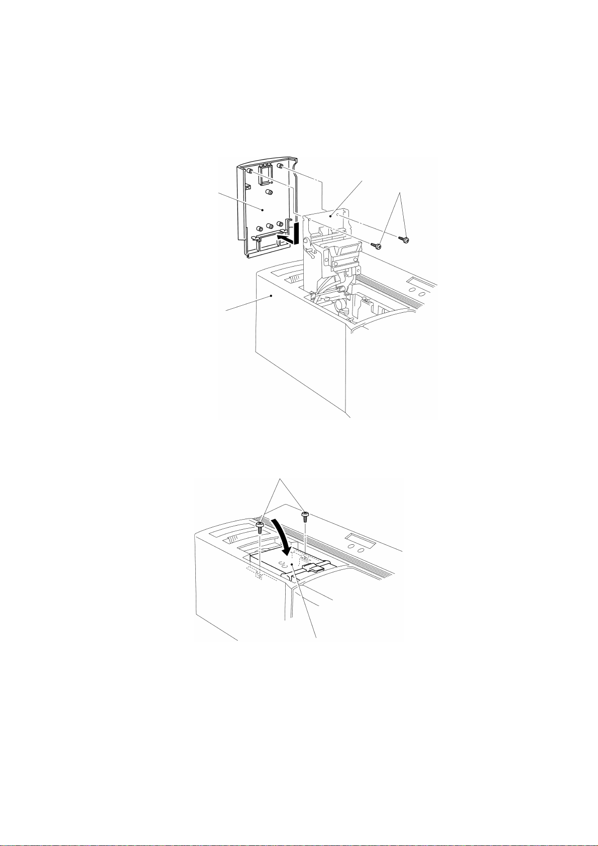
1.6 Disassembly of the Body Cover
Turn the machine over with the right side up, open the cassette cover, and remove
the two screws to remove the cassette cover, as shown in Fig. 3.11.
Cassette cover
Body cover
Head holder assy
Screws
Fig. 3.11
Close the head holder assy and remove the two screws, as shown in Fig. 3.12.
Screws
Head holder assy
Fig. 3.12
III - 9
Page 28
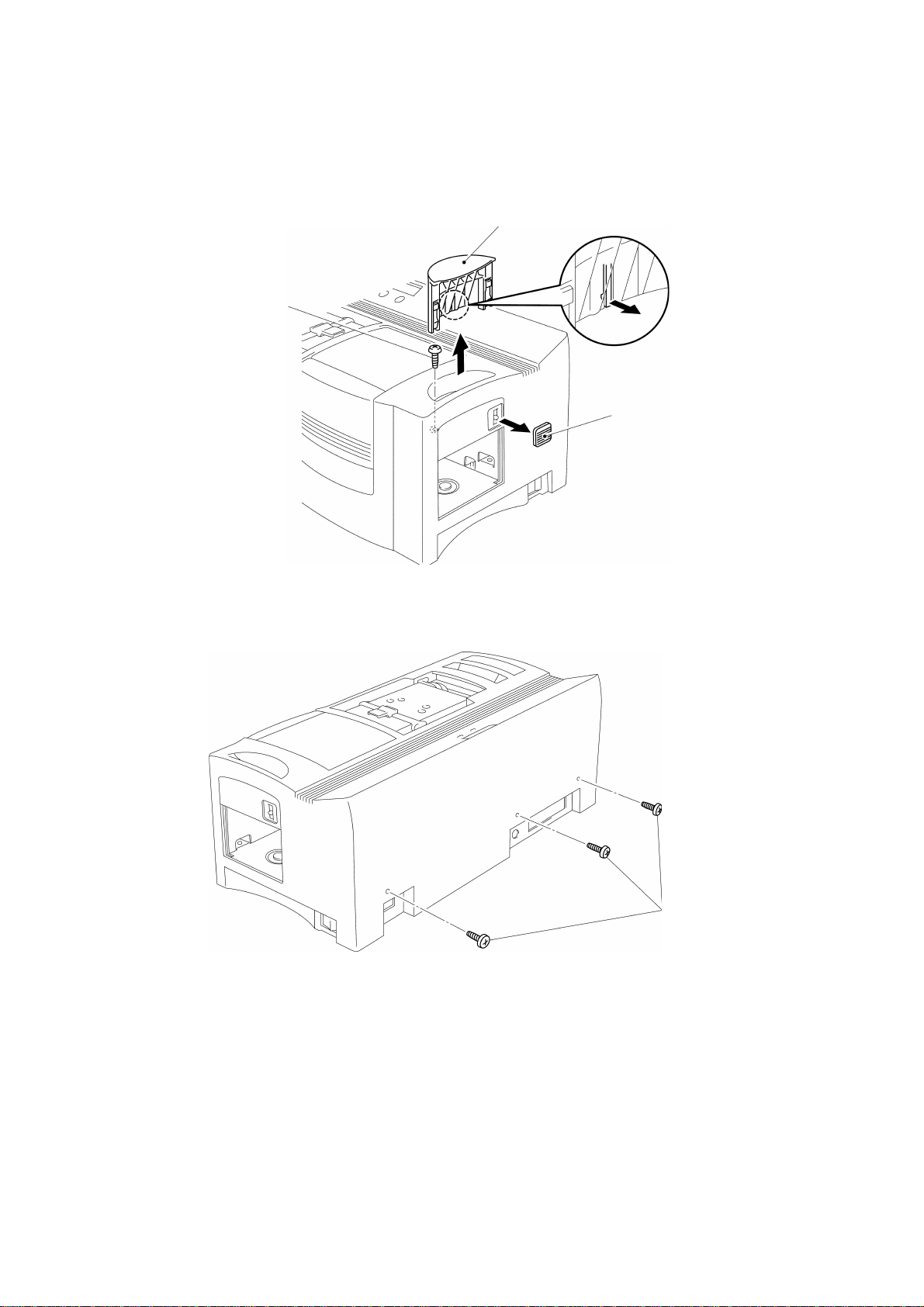
Remove the eject cover and the screw.
Remove the slide lever, as shown in Fig. 3.13.
Eject cover
Screw
Fig. 3.13
Slide lever
Remove the three screws in the back of the cover, and remove the body cover by
lifting it, as shown in Figs. 3.14 and 3.15.
Screws
Fig. 3.14
III - 10
Page 29

Body cover
Bottom cover
Fig. 3.15
Remove the two screws to remove the control panel PCB holder from the body
cover. Remove the screw from the control panel PCB holder to remove the control
panel PCB assy, as shown in Fig. 3.16.
Screw
Control panel
PCB assy
Control panel PCB holder
Screws
Body cover
Fig. 3.16
III - 11
Page 30
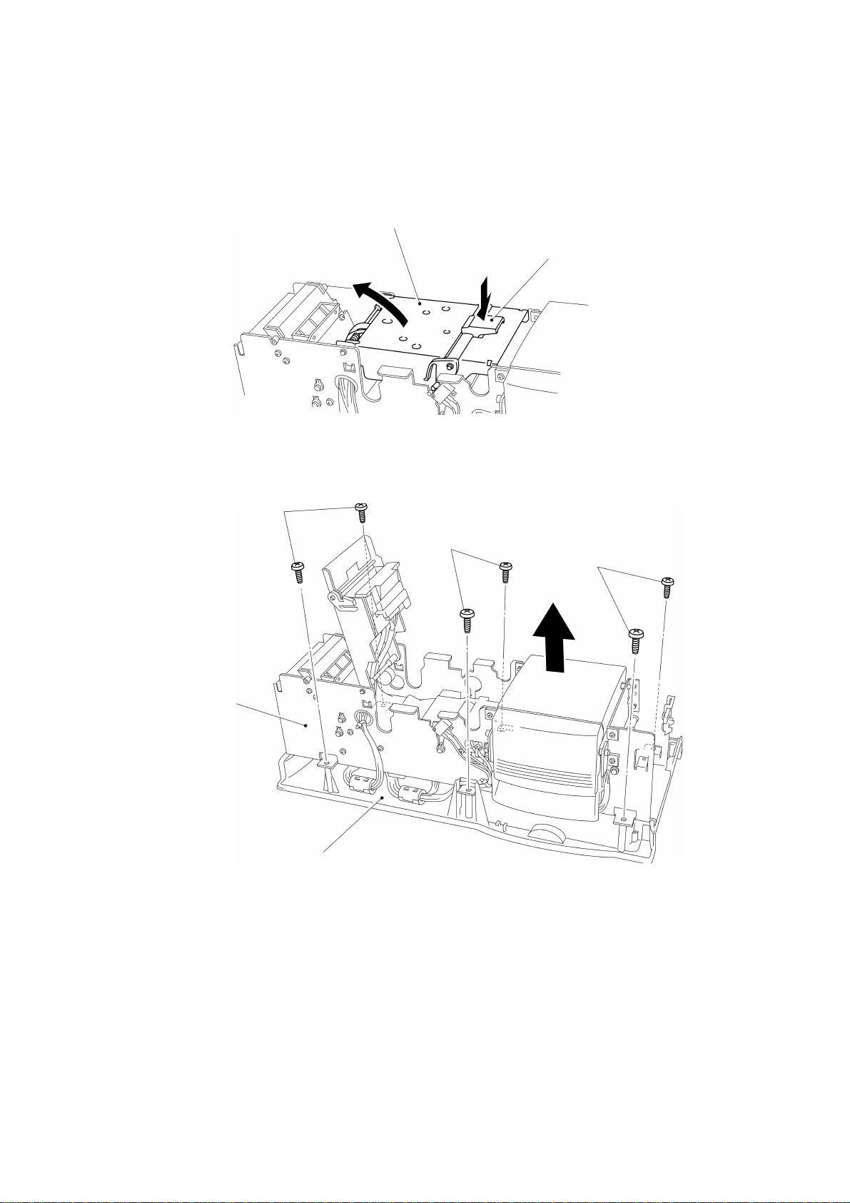
1.7 Disassembly of the Main Chassis and the Bottom Cover
Press the open button to open the head holder assy, as shown in Fig. 3.17.
Head holder assy
Open button
Fig. 3.17
Remove the six screws to remove the main chassis from the bottom cover, and
remove the two cores, as shown in Fig. 3.18.
Screws
Screws
Screws
Main chassis
Bottom cover
Fig. 3.18
III - 12
Page 31

Remove the two screws to remove the ground wire from the PS PCB shield plate
and the main chassis, as shown in Fig. 3.19.
Screw
Main chassis
Ground wire
Screw
PS PCB shield plate
Fig. 3.19
Remove the size detection PCB harness from the bottom cover, as shown in Fig.
3.20.
Main chassis
Size detection PCB harness
Fig. 3.20
Bottom cover
III - 13
Page 32

Remove the harness coming out of the main chassis from the bottom cover, as
shown in Fig. 3.21.
Main chassis
Bottom cover
Fig. 3.21
III - 14
Page 33

1.8 Disassembly of the Power Supply PCB Assy
Turn the bottom cover over, and remove the two screws securing the power supply
PCB assy on the bottom cover to remove the power supply PCB assy. Then,
remove the PS PCB shield plate, as shown in Fig. 3.22.
Note: Put on a static control wrist band before handling PCBs.
Power supply PCB assy
PS PCB shield plate
Screws
Bottom cover
Fig. 3.22
III - 15
Page 34

1.9 Disassembly of the Thermal Head Unit
Cut two fastening bands L100 that secure the harness on the main chassis, as
shown in Fig. 3.23.
Free bush 50
Fastening
band L100
Hole
Main chassis
Fastening
band L100
Fig. 3.23
Press the open button to open the head holder assy.
Pull parts A of the head protection cover in the direction of the arrow to remove it
from the head guide shaft.
Remove the two screws to remove the thermal head unit from the head holder, as
shown in Fig. 3.24.
Free bush 15
Harness
Note: Take care not to touch the thermal head heat generating points.
A
Head guide shaft
Head protection cover
Head holder
Thermal head unit
Screws
Fig. 3.24
III - 16
Page 35

1.10 Disassembly of the Sensor Assys
Remove the screw to remove reflective sensor assy A from the head holder.
Remove the screws to remove reflective sensor assys B and C from the sensor
brackets.
Remove the screw to remove transparent sensor assy A from the film path.
Remove the screw to remove transparent sensor assy B from the presser unit assy,
as shown in Fig. 3.25.
Head holder assy
Screw
Screw
Reflective sensor assy C
Reflective sensor assy A
Reflective sensor assy B
Screw
Fig. 3.25
Screw
Transparent
sensor assy A
Transparent
sensor assy B
Screw
III - 17
Page 36

1.11 Disassembly of the Micro Switches
Remove the screw to remove micro switch assy A for cassette cover open/close
detection from the main chassis, as shown in Fig. 3.26.
Micro switch assy A
Screw
Fig. 3.26
Remove the screw to remove micro switch assy B for xenon reset from the main
chassis.
Main chassis
Slide and pull out the xenon lock claw in the directions of arrows, as shown in Fig.
3.27.
Main chassis
Xenon lock claw
Micro switch assy B
Fig. 3.27
Screw
III - 18
Page 37

1.12 Disassembly of the Platen Unit Assy
After removing the two screws, lift the platen unit assy in the directions of the
arrows, as shown in Fig. 3.28.
Main chassis
Platen unit assy
Fig. 3.28
Screws
Slide the platen unit assy in the direction of arrow 1, pass gear A through the hole in
the main chassis, turn the projection of the bearing down, tilt the platen unit assy in
the direction of arrow 2, and pull it out in the direction of arrow 3, as shown in Fig.
3.29.
A
Platen unit assy
Main chassis
Bearing
3
2
1
Fig. 3.29
III - 19
Page 38

Subsequently, separate the film guide from the platen unit, as shown in Fig. 3.30.
Film guide
Platen unit
Fig. 3.30
III - 20
Page 39

1.13 Disassembly of the Presser Unit Assy
Open the presser unit cover in the direction of the arrow.
Remove the 12 screws securing the presser unit assy on the main chassis to
remove the presser unit assy, as shown in Fig. 3.31.
Screws
Screws
Presser unit cover
Screws
Screws
Fig. 3.31
III - 21
Page 40

Remove the four retaining rings to remove the presser plate hinge shaft from the
presser frame sub assy, as shown in Fig. 3.32.
Retaining ring
Presser plate
Presser plate hinge shaft
Retaining ring
Retaining rings
Presser frame sub assy
Fig. 3.32
While bending two claws A of the presser plate cover and the presser plate in the
directions of the arrows, remove the presser plate cover, as shown in Fig. 3.33.
Presser plate cover
Presser plate
A
A
Fig. 3.33
III - 22
Page 41

Remove the two retaining rings to remove the presser plate positioning shaft from
the presser plate.
While bending the four claws in the directions of the arrows, remove the presser
lever cover, as shown in Fig. 3.34.
Presser lever cover
Presser lever
Retaining ring
Positioning presser plate
Presser plate
Retaining ring
Presser plate positioning shaft
Fig. 3.34
III - 23
Page 42

Remove the two presser bearings, and then pull the presser plate lever shaft and
presser plate lock shaft out from the presser lever, as shown in Fig. 3.35.
Presser lever
Presser bearing
Presser plate lever shaft
Presser bearing
Presser plate lock shaft
Presser plate lock spring
Presser plate lock
Fig. 3.35
III - 24
Page 43

Remove the two retaining rings and the two bearings to remove the presser frame
shaft.
While bending the four claws and the two tongues, remove the shutter cover from
the presser frame sub assy.
Remove the two shutter springs from the shutter front and the shutter rear.
Remove the shutter front, shutter rear, and the two pinions 14 from the presser
frame sub assy.
Remove the three screws to remove the shield plate rear and the size detection
PCB assy from the shutter rear, as shown in Fig. 3.36.
Shutter cover
Tongue
Shutter
front
Shutter springs
Shutter rear
Shutter front
Retaining
ring
Bearing
Presser frame shaft
Pinions 14
Shutter rear
Size detection PCB assy
Shield plate rear
Screws
Presser frame sub assy
Bearing
Retaining ring
Fig. 3.36
III - 25
Page 44

1.14 Disassembly of the Head Holder Assy
Remove hooks A of the two head holder springs from the grooves of the main
chassis.
Remove the two retaining rings and pull out the rotation shaft in the direction of the
arrow, as shown in Fig. 3.37.
Head holder guide
Retaining ring
Main chassis
Head guide spring
Retaining ring
Rotation shaft
Head holder springs
A
Fig. 3.37
III - 26
Page 45

Remove the two retaining rings and pull out the lever shaft in the direction of the
arrow, and remove the lever hook.
Remove the two retaining rings and pull out the head guide shaft in the direction of
the arrow, as shown in Fig. 3.38.
Lever hook
Lever shaft
Head guide shaft
Head holder
Lever hook
return spring
Head holder guide
Compression springs
Protection cover spring
Fig. 3.38
III - 27
Page 46

1.15 Disassembly of the Gears and Pulleys
Remove the gears and pulleys in the numerical order shown in Fig. 3.39.
Gear 25
Pulley 18
Gear 50A
Ã
Pulley 25
Â
Gear 19/84
Á
Gear 20/50
Gear 21/47
Gear 20/50
À
Gear 44
Gear 21/47
Ä
Gear 68
Å
Ç
Æ
Fig. 3.39
III - 28
Page 47

1.16 Disassembly of the Motor Holder Assy and the Motors
Remove the three screws securing the motor holder sub assy on the main chassis
to remove the motor holder sub assy.
Remove the two screws to remove the main motor from the motor holder sub assy.
Remove the two screws to remove the paper feed motor from the main chassis, as
shown in Fig. 3.40.
Paper feed motor
Screws
Screws
Main motor
Motor holder sub assy
Fig. 3.40
Screws
Main chassis
III - 29
Page 48

1.17 Disassembly of the Rollers
Remove the two retaining rings and bearings to remove the driving roller.
Remove the retaining ring, paper eject roller spring, and two bearings to remove the
paper eject roller.
Remove the two retaining rings and bearings to remove the paper feed roller.
Remove the clutch spring, the washer, and the retaining ring from the paper feed
roller.
Remove the two retaining rings to remove the nip roller, as shown in Fig. 3.41.
Bearing
Retaining
ring
Retaining ring
Bearing
Retaining ring
Retaining ring
Bearing
Bearing
Driving
roller
Clutch spring
Washer
Retaining ring
Nip roller
Retaining ring
Paper feed roller
Bearing
Retaining
ring
Retaining ring
Paper eject roller
Bearing
Paper eject roller spring
Fig. 3.41
III - 30
Page 49

1.18 Disassembly of the Label Guide Assy
Remove the five screws securing the label guide assy on the main chassis, and
remove the label guide assy by pressing projections A and B of the label guide to
release them from the holes, as shown in Fig. 3.42.
Screws
Screw
A
Label guide assy
B
Screws
Main chassis
Fig. 3.42
III - 31
Page 50

Remove label nip springs R and L.
Remove the two screws to remove the sensor bracket from the label guide.
Remove the two retaining rings to remove the ribbon cassette shaft from the label
guide, as shown in Fig. 3.43.
Label guide
Label nip spring L
Retaining ring
Label nip spring R
Ribbon cassette shaft
Fig. 3.43
Sensor bracket
Screws
III - 32
Page 51

1.19 Disassembly of the Film Path Assy
Remove the two retaining rings and bearings to remove the paper feed roller.
Remove the clutch spring, the washer, and the retaining ring from the paper feed
roller.
Remove the seven screws securing the film path assy on the main chassis, press
two projections A of the film path to release them from the holes, and remove the
film path assy.
Remove torsion springs R and L.
Remove the two retaining rings to remove the nip roller, as shown in Fig. 3.44.
Paper feed roller
Film path assy
Main chassis
Bearing
Retaining ring
Screws
A
Retaining ring
Fig. 3.44
Bearing
A
Retaining ring
Screws
Retaining ring
Torsion springs
R and L
Nip roller
III - 33
Page 52

Remove the retaining rings, pull out the two outer plate shafts, and remove the
outer plate, the lock plate, and the two return springs.
Remove the two screws to remove the sensor bracket.
Remove the two magazine springs, and the magazine lift sub assy while pressing
parts A and B of the film path to release them, as shown in Fig. 3.45.
Screw
Screw
Magazine lift
sub assy
B
Sensor bracket
A
Magazine springs
Film path
Lock plate
Outer plate shafts
Outer plate
Retaining ring
Retaining ring
Return spring
Return spring
Fig. 3.45
III - 34
Page 53

1.20 Disassembly of the Drawer Connector
Remove the two screws to remove the drawer connector from the main chassis, as
shown in Fig. 3.46.
Screws
Main chassis
Drawer connector
Fig. 3.46
Remove free bush 50, and free bushes 15 and 70, as shown in Fig. 3.47.
Main chassis
Free bush 50
Free bush 15
Free bush 70
Fig. 3.47
III - 35
Page 54

2. REASSEMBLY PROCEDURES
2.1 Reassembly of the Drawer Connector
Set free bush 50, and free bushes 15 and 70 on the holes in the main chassis, as
shown in Fig. 3.48.
Main chassis
Free bush 50
Free bush 15
Free bush 70
Fig. 3.48
Pass the drawer connector assy harness through hole A in the main chassis. Insert
the drawer connector into hole B, and secure it with the two screws, as shown in
Fig. 3.49.
Note: Insert the drawer connector so that its projection will be inserted into groove
D of the main chassis.
Drawer connector assy
Projection
Main chassis
Hole B
Groove D
Hole A
Fig. 3.49
III - 36
Page 55

2.2 Reassembly of the Film Path Assy
While bending two parts A of the film path in the directions of the arrows, insert
them into the holes in the magazine lift sub assy, as shown in Fig. 3.50.
Magazine lift sub assy
Fig. 3.50
Set the two magazine springs on two hooks B of the film path assy, and then two
hooks C of the magazine lift sub assy, as shown in Fig. 3.51.
Parts A
Film path
Magazine lift sub assy
Hooks C
Film path assy
Magazine springs
Hooks B
Fig. 3.51
III - 37
Page 56

After setting the sensor bracket on two parts D of the film path assy, set the film
path assy so that the two locating pins on the film path assy will be inserted into
holes E in the sensor bracket, and secure the film path assy with the two screws, as
shown in Fig. 3.52.
Screws
Sensor bracket
Locating pin
Sensor bracket
Film path
Holes E
Locating pin
Film path
Part D
Fig. 3.52
III - 38
Page 57

Pass one outer plate shaft through the hole in the film path in the direction of the
arrow, through the holes in the outer plate, the return spring, and the hole on the
opposite side of the film path, before setting the retaining ring on the outer plate
shaft.
Note 1: The hook of the return spring must be between the ribs of the film path, as
shown in Fig. 3.53.
Ribs
Outer plate shaft
Outer plate
Film path
Retaining ring
Hook
Return spring
Outer plate
Film path
Fig. 3.53
III - 39
Page 58

In the same manner, pass the other outer plate shaft through the hole in the film
path in the direction of the arrow, through the holes in the lock plate, the return
spring, and the hole on the opposite side of the film path, before setting the
retaining ring on the outer plate shaft.
Note 2: The hook of the return spring must be outside the rib of the film path, as
shown in Fig. 3.54.
Film path
Outer plate
shaft
Return spring
Lock plate
Rib
Film path
Return spring
Lock plate
Fig. 3.54
III - 40
Page 59

Set torsion spring R on the projection of the main chassis so that hook A of torsion
spring R will be inserted into the hole in the main chassis.
In the same manner, set torsion spring L on the opposite side.
Pass each end of the nip roller through the hole from the inside of the main chassis,
and set the retaining rings on both ends of the nip roller from the outside of the
main chassis.
Set the film path in the main chassis, and secure it with the seven screws.
Note 3: Insert the hooks of the torsion springs into the grooves of the nip roller.
Note 4: Make sure that part D of the outer plate is inserted into hole E in the main
chassis, as shown in Fig. 3.55.
Paper feed roller
Film path
Main
chassis
Retaining
ring
Bearing
Screws
Retaining ring
Bearing
E
Torsion springs
Retaining ring
Screws
Retaining ring
D
A
Nip roller
Film path
Outer
plate
Fig. 3.55
III - 41
Main
chassis
Page 60

2.3 Reassembly of the Label Guide Assy
Set the retaining ring, the washer, and the clutch spring on the paper feed roller
shaft.
Note 1: Before setting the clutch spring, apply grease on the shaft.
Pass end A of the paper feed roller through the hole in the main chassis from the
inside, and then pass end B through the hole on the opposite side of the main
chassis.
Set the bearings and the retaining rings on both ends of the paper feed roller from
the outside of the main chassis. (Insert the hook of the clutch spring into the groove
of the bearing, as shown in Fig. 3.56.)
Paper feed roller
Retaining ring
Washer
Clutch spring
A
B
Main chassis
Groove
Bearing
Retaining ring
Clutch spring
Hook
Bearing
Paper feed roller
Fig. 3.56
Bearing
Retaining ring
III - 42
Page 61

Set the sensor bracket on the two locating pins on the label guide, and secure the
sensor bracket on the label guide with the two screws.
Set label nip spring L on the pin on the label guide, and set the two hooks of the
label nip spring L in hook A and then hook B of the label guide.
Set the ribbon cassette shaft on the label guide, and set the two retaining rings on
the ribbon cassette shaft.
In the same manner, set label nip spring R, as shown in Fig. 3.57.
Label guide
Locating pin
Locating pin
B
A
Label nip spring L
Ribbon cassette roller
Label nip
spring R
Sensor bracket
Screws
Fig. 3.57
III - 43
Page 62

While bending two parts D of the label guide assy to the inside, set the label guide
assy in the main chassis.
Secure the label guide assy in the main chassis with the five screws.
Note 2: Make sure that two parts D of the label guide is properly inserted into the
holes in the main chassis, as shown in Fig. 3.58.
Screws
Label guide
Screw
D
D
Screws
Fig. 3.58
Main chassis
III - 44
Page 63

2.4 Reassembly of the Rollers
While pressing ends A of the label nip springs in the directions of the arrows, pass
each end of the nip roller through the hole from the inside of the main chassis.
Slide the label nip springs so that their ends A will contact parts B of the nip roller.
Note 1: Check that ends A of the label nip springs make contact with parts B of the
nip roller, then apply grease to parts B of the nip roller.
Set the retaining rings on both ends of the nip roller from the outside of the main
chassis. Then, set the paper guide on the sensor bracket, as shown in Fig. 3.59.
Nip roller
Sensor bracket
Label guide assy
Label nip spring
Retaining ring
Paper guide
Retaining ring
Label guide
Label nip spring
End A
Label nip spring
Part B
Nip roller
Main chassis
Fig. 3.59
III - 45
Page 64

Set the retaining ring, the washer, and the clutch spring on the paper feed roller.
Note 2: Before setting the clutch spring, apply grease to the portion on the paper
feed roller where the clutch spring is to make contact with.
Insert end A of the paper feed roller into the hole in the main chassis from the
inside, and end B of the paper feed roller into the hole on the opposite side of the
main chassis, while pressing the nip roller.
Set the bearings and the retaining rings on both ends of the paper feed roller from
the outside of the main chassis, as shown in Fig. 3.60.
(Insert the hook of the clutch spring into the groove of the bearing.)
A
Paper feed roller
Retaining ring
Washer
Clutch spring
Bearing
Retaining ring
Fig. 3.60
B
Bearing
Nip roller
Retaining ring
III - 46
Page 65

Insert end A of the driving roller into the hole in the main chassis from the inside,
and then insert end B of the driving roller into the hole on the opposite side of the
main chassis.
Set the bearings and the retaining rings on both ends of the driving roller from the
outside of the main chassis.
Insert both ends of the paper eject roller through the holes of the main chassis.
Set the bearings on both ends of the paper eject roller.
Set the retaining ring on the left end of the roller, and the paper eject roller spring
on the other end of the roller, as shown in Fig. 3.61.
Note 3: Fit the end of the paper eject roller spring in the groove of the bearing.
Note 4: Before setting the paper eject roller spring, apply grease to the portion on
the paper eject roller where the spring is to make contact with.
A
Driving roller
Bearing
Retaining ring
B
Bearing
Bearing
Retaining ring
Retaining
ring
Paper eject roller
B
A
Bearing
Main chassis
Paper eject roller spring
Bearing
Paper eject roller spring
Fig. 3.61
III - 47
Page 66

2.5 Reassembly of the Motor Holder Assy and the Motors
Set the main motor in the hole in the motor holder sub assy so that the end of the
harness will be at a lower position, and secure the main motor on the motor holder
sub assy with the two screws.
Set the motor holder sub assy on locating embosses A on the main chassis, and
secure the motor holder sub assy on the main chassis with the three screws.
Set the paper feed motor in the hole in the main chassis so that the end of the
harness will be at a lower position, and secure the paper feed motor on the main
chassis with the two screws.
Pass the paper feed motor harness to the outside of the main chassis through hole
B from the inside of the main chassis, as shown in Fig. 3.62.
A
Motor holder sub assy
Paper feed motor
Screws
Screws
Main
chassis
Screws
Main motor
B
Fig. 3.62
III - 48
Page 67

2.6 Reassembly of the Gears and Pulleys
(1) Set gear 21/47 on shaft A.
(2) After inserting shaft B through the clutch spring A, set gear 20/50.
(3) After inserting shaft C through the clutch spring A, set gear 68 and the
retaining ring.
(4) Set gear 21/47 and the retaining ring on shaft D.
(5) Set the clutch spring C on gear 25, and set gear 25 and then gear 50A on shaft
E.
Insert the hook of the clutch spring C into the groove of gear 50A, and set the
retaining ring.
(6) Set pulley 25 and gear 19/84 on shafts F and G respectively, and set the timing
belt (MXL belt B69) on pulley 25 and gear 19/84.
Set the flanges and the retaining rings on shafts F and G.
(7) Set pulley 18 on shaft H.
Set the timing belt (MXL belt 221) on shaft H and gear 44, and set gear 44 and
the retaining ring on shaft I.
Set the flange and the retaining ring on shaft H.
Note: Check that the end of the paper eject roller spring is fitted in the groove of the
bearing.
(8) Set gear 20/50, the flange, and then retaining ring on shaft J, as shown in Fig.
3.63
III - 49
Page 68

Bearing
Shaft H
Shaft E
Shaft G
Paper eject
roller spring
Pulley 18
Pulley 25
MXL belt 221
Gear 19/84
Gear 20/50
Gear 25
Clutch spring C
Gear 50A
Gear 44 Gear 21/47 Gear 68
MXL belt B69
Shaft F
Fig. 3.63
Shaft I
Shaft J
Gear 20/50
Shaft D
Shaft A
Shaft B
Shaft C
Gear 21/47
Clutch spring A
III - 50
Page 69

2.7 Reassembly of the Head Holder Assy
Place two compression springs on two burrs of the head holder as shown in
Fig.3.64. Hook two catches A of the head holder on the head holder guide, then fit
two burrs of the head holder guide over the compression springs.
Lower the head holder guide. Insert the head guide shaft through the head holder
guide, head holder, and protection cover spring, then mount the retaining rings on
both ends of the shaft.
Move the protection cover spring toward the end of the shaft, then fit arm B of the
protection cover spring in portion B of the head holder.
Assemble the head protection cover so that portions D fit over the head guide shaft,
then fit arm C of the protection cover spring in the hook of the head protection
cover.
Hooks A of the head
holder mate with these parts.
Head holder guide
Head guide shaft
Compression springs
Hooks A
Burrs
Head holder
B
Arm B
Protection cover spring
Arm C
Hook
D
Head protection cover
Fig. 3.64
III - 51
Page 70

Set the lever hook on the head holder guide, insert the lever shaft into the hole in
the head holder guide, pass the lever shaft through the lever hook return spring,
and insert the lever shaft into the hole on the opposite side of the head holder guide
in the direction of the arrow. Then, set the retaining rings on both ends of the lever
shaft, as shown in Fig. 3.65
Lever hook
Lever shaft
Stopper
Head holder guide
Head holder guide
Lever hook return spring
Lever hook
Head holder guide
Fig. 3.65
III - 52
Page 71

Pass the rotation shaft through the hole in the main chassis from the outside in the
direction of the arrow.
Pass the rotation shaft through the head guide spring, the head holder assy, head
holder springs R and L, and the hole on the opposite side of the main chassis, and
set the two retaining rings on the rotation shaft.
Set the hooks of head holder springs R and L on the projections of the main
chassis, as shown in Fig. 3.66.
Head holder assy
Head guide spring
Head holder spring R
Retaining ring
Head holder spring L
Retaining ring
Rotation shaft
Main chassis
Fig. 3.66
III - 53
Page 72

2.8 Reassembly of the Presser Unit Assy
Set the size detection PCB assy and the shield plate rear on the shutter rear, and
secure them with the three screws.
Set two pinions 14 on the two shafts in the presser frame sub assy.
Set the shutter rear and then the shutter front, as shown in Fig. 3.67.
Shutter front
Shutter rear
Size detection
PCB assy
Shield plate rear
Presser frame sub
assy
Pinions 14
Fig. 3.67
III - 54
Page 73

Adjust the ends of the ribs of the shutter rear to the centers of the pinion shafts.
Set the shutter front so that there will be no clearance between the ends of the ribs
of the shutter front and those of the shutter rear, as shown in Fig. 3.68.
Shutter rear
Shutter front
Fig. 3.68
III - 55
Page 74

Set the two shutter springs on the two hooks of the shutter front and the shutter
rear.
Insert the four claws of the shutter cover into the holes in the presser frame sub
assy.
Pass the presser frame shaft through the presser frame sub assy, and set the
retaining rings and the bearings on both ends of the presser frame shaft.
Note 1: Make sure that the two pinion shafts of the presser frame sub assy are
inserted into two holes A in the shutter cover, as shown in Fig. 3.69.
Shutter cover
Hole A
Shutter springs
Presser frame
sub assy
Retaining ring
Bearing
Presser frame shaft
Bearing
Retaining ring
Fig. 3.69
III - 56
Page 75

Pass the positioning shaft through the presser plate and the positioning presser
plate, and set the retaining rings on both ends of the positioning shaft.
Pass the presser plate lock shaft through the hole in the presser lever from the
outside in the direction of the arrow.
Pass it through the presser plate lock, the presser plate lock spring, and through the
hole on the opposite side of the presser lever.
Insert hook A of the presser plate lock spring into the hole C in the presser lever.
Pass the presser plate lever shaft through the presser plate and the presser lever.
Set the presser bearings on both ends of the presser plate lever shaft.
Set the presser lever cover on the presser lever.
Note 2: Make sure that two hooks B of the presser lever cover and the two locating
pins are properly set, as shown in Fig. 3.70.
Presser lever
cover
B
Presser bearing
Presser lever
Presser plate
lock spring
Presser plate lock
Positioning presser plate
Presser plate
C
A
Fig. 3.70
Presser plate lever shaft
Presser bearing
Presser plate lock shaft
Positioning shaft
III - 57
Page 76

Pass the hinge shaft through the hole in the presser frame sub assy from the
outside in the direction of the arrow.
Pass it through the presser plate hinge spring, the presser plate, and the hole on
the opposite side of the presser frame sub assy, and set the four retaining rings, as
shown in Fig. 3.71.
Presser plate hinge spring
Hook
Hinge shaft
Shutter cover
Presser frame sub assy
Fig. 3.71
III - 58
Page 77

On assembling the presser unit assy with the main chassis, adjust the position using
the presser jig assy and adjustment jig according to the following steps.
Note 3: Use caution when handling and taking custody of the jigs.
(1) Place the main chassis on the presser jig assy (part of the presser base assy)
at the specified position, as shown in Fig. 3.72A.
Note 4: Check that there is not any gap (A) between the main chassis and presser
jig assy.
Locating pin
Locating pins
Main chassis
Locating pin
Presser jig assy
(part of the presser
base assy)
Locating pins
Locating pins
A
Fig. 3.72A
(2) Place the presser sub unit assy on the main chassis, as shown in Fig. 3.72B.
Head holder assy
Presser sub unit assy
Main chassis
Fig. 3.72B
III - 59A
Page 78

(3) Open the presser plate, then place the adjustment jig in the presser sub unit
assy, as shown in Fig. 3.72C.
Adjustment jig
Presser plate
Presser frame sub assy
Main chassis
Fig. 3.72C
(4) Close the presser plate.
Note 5: Check that the presser plate is locked (B), as shown in Fig. 3.72D.
Presser frame shaft
Presser sub unit assy
Presser plate lock
Fig. 3.72D
B
Main chassis
(5) Align the presser frame sub assy with the main chassis at four portions (C),
with no gap being allowed between them, as shown in Fig. 3.72C.
III - 59B
Page 79

(6) Place the presser jig assy on the presser frame sub assy, as shown in Fig.
3.73A.
Note 6: Before securing the presser jig assy, check the following items.
Presser side plate
Presser hook base
Presser jig assy
(part of the presser base assy)
D
Catch clip assy
Presser hook
Presser side plate
D
Presser frame sub assy
Main chassis
Fig. 3.73A
* Check that the presser frame sub assy is aligned with the main chassis at four
portions (C), with no gap being allowed between them, as shown in Fig. 3.72C.
* Check that the harnesses including the FPC are not caught between the presser
jig assy and presser frame sub assy.
* Check that the presser frame sub assy and main chassis fit in four dented portions
(D) on the presser side plates R/L of the presser jig assy, as shown in Fig. 3.73A
and Fig. 3.73B.
F
(It is impossible to check
the item by taking a look.)
Presser hook base
D
Presser hookPresser hook
Main chassis
Presser frame sub assy
Presser side plate
D
Fig. 3.73B
III - 59C
Page 80

* Check that the frame of the presser frame sub assy supports the side plates R/L
base assy)
of the presser jig assy from inside (E).
Also check that the protrusion (F) of the presser jig assy presses the frame of the
presser frame sub assy downward by checking that D and E are properly set, as
shown in Fig. 3.73A to Fig. 3.73C.
Side plate L
(Presser jig assy)
Side plate R
(Presser jig assy)
EE
Frame
(Presser frame sub assy)
Frame
(Presser frame sub assy)
Fig. 3.73C
* Check that the protrusion of the presser frame sub assy fit in the hole of the main
chassis at two portions (G), as shown in Fig. 3.73D.
Presser jig assy
Presser frame sub assy
Presser sub
unit assy
G (It is possible to check
the item by taking a look.)
Main chassis
Presser jig assy
(part of the presser
G (It is impossible to check
the item by taking a look.)
Fig. 3.73D
(7) Secure the presser jig assy using two catch clip assys, as shown in Fig. 3.73A.
Note 7: Lock the presser jig assy at its front and rear in this order.
III - 60A
Page 81

(8) Tighten ten screws in the order specified in Fig. 3.74A to 3.74B.
base assy)
Note 8: Tighten those screws twice.
Pressser jig assy
Main chassis
Screws
Presser sub unit assy
Fig. 3.74A
Screws
Main chassis
Presser jig assy
(part of the presser
Presser jig assy
(9) Remove the presser jig assy.
Screw
Screws
Screws
Fig. 3.74B
III - 60B
Page 82

(10) Open the presser plate, then tighten two screws, as shown in Fig. 3.74C.
Note 9: Tighten those screws twice.
Presser plate
Adjustment jig
Main chassis
Screws
Fig. 3.74C
(11) Remove the presser jig assy (part of the presser base assy) and adjustment jig.
(12) Attach the presser plate cover to the presser plate, as shown in Fig. 3.74D.
Note 10: Check that two hooks and locating pins of the presser plate cover fit in
the holes of the presser plate.
Hooks
Presser plate cover
Locating pins
Presser plate
Main chassis
Fig. 3.74D
III - 60C
Page 83

2.9 Reassembly of the Platen Unit Assy
Set the platen unit on the film guide, as shown in Fig. 3.75.
Fig. 3.75
Insert part A of the platen unit assy into the hole in the main chassis from the inside.
Then, insert part B of the platen unit assy into the hole on the opposite side of the
main chassis, and insert the platen unit assy into the two grooves of the main
chassis, with the projection of the bearing turned upwards, as shown in Fig. 3.76.
Film guide
Platen unit
Set part C of the platen unit assy between the two ribs of the film path.
B
Platen unit assy
Main chassis
Bearing
Fig. 3.76
C
A
III - 61
Page 84

Secure the platen unit assy with the two screws, as shown in Fig. 3.77.
Screws
Main chassis
Platen unit assy
Fig. 3.77
III - 62
Page 85

2.10 Reassembly of the Micro Switches
Set hole A in the micro switch assy A for cassette cover open/close detection on the
emboss on the main chassis.
Screw the switch on the main chassis where hole B in the switch and the hole in the
main chassis overlap, as shown in Fig. 3.78.
Hole A
Hole B
Screw
Micro switch assy A
(for cassette cover open/close detection)
Fig. 3.78
Insert part A of the xenon lock claw into hole B in the main chassis.
Emboss
While bending the resin spring, insert the two hooks of the xenon lock claw into two
holes C in the main chassis.
Set hole D in the micro switch assy B for xenon reset on the emboss on the main
chassis.
Screw the switch on the main chassis where hole E in the switch and the hole in the
main chassis overlap. Then, secure the harness of the switch for xenon reset with
the fastening band, as shown in Fig. 3.79.
Hole B
Hole C
A
Xenon lock claw
Main chassis
Emboss
Hole E
Hole D
Screw
Micro switch assy B
(for xenon reset)
Fig. 3.79
III - 63
Page 86

2.11 Reassembly of the Sensor Assys
Secure reflective sensor assy A on the head holder with the screw.
Pass the reflective sensor assy A harness between the rotation shaft and the head
holder guide, and pass it through hole E in the main chassis and to the outside.
Secure reflective sensor assys B and C on the sensor brackets with the screws.
Pass the harnesses of reflective sensor assys B and C through hole E in the main
chassis and to the outside.
Secure transparent sensor assy A on the film path with the screw.
Pass the transparent sensor assy A harness through hole F in the main chassis and
to the outside.
Insert transparent sensor assy B in the direction of the arrow, and secure it on the
presser unit assy with the screw.
Pass fastening band L100 through holes E and F, and secure the harness coming
out of hole E and F in the main chassis, as shown in Fig. 3.80.
Rotation
Head holder assy
shaft
Head holder
Screw
Label guide assy
Hole E
Main chassis
Fastening
band L100
Hole
Free bush 50
Reflective sensor
assy C
Transparent
sensor assy A
Reflective sensor assy A
Reflective sensor assy B
Screw
Screw
Fastening band
L100
Transparent
sensor assy A
Screw
Transparent
sensor assy B
Hole F
Screw
Free bush 15
Fig. 3.80
III - 64
Page 87

2.12 Reassembly of the Thermal Head Unit
Fig. 3.81 shows the thermal head unit.
Caution: Take care not to touch the thermal head heat generating points.
Heat generating points
Thermal head unit
Fig. 3.81
Set the thermal head unit on the two embosses on the head holder, and secure it
with the two screws.
Pass the thermal head unit harness between the rotation shaft and the head holder
guide, and pass it through the hole in the main chassis and to the outside, as shown
in Fig. 3.82.
Thermal head unit
Screws
Fig. 3.82
Secure the thermal head unit harness on the main chassis with fastening band
L100, that is also used to secure the sensor assy, as shown in Fig. 3.80.
III - 65
Page 88

2.13 Reassembly of the Power Supply PCB Assy
Insert two parts A of the PS PCB shield plate into two holes B in the bottom cover.
After setting the power supply PCB assy on the two hooks C of the bottom cover,
set the power supply PCB assy on the locating boss on the bottom cover, and
secure the power supply PCB assy on the bottom cover with the two screws, as
shown in Fig. 3.83.
Note: Put on a static control wrist band before handling PCBs.
Power supply
PCB assy
Screw
A
PS PCB shield plate
Screw
Bottom cover
C
Locating boss
C
B
Fig. 3.83
III - 66
Page 89

2.14 Reassembly of the Bottom Cover and the Main Chassis
B
Insert the end of the size detection PCB harness into the hole in the bottom cover,
and set it into hooks A, B, C, and D, as shown in Fig. 3.84.
Size detection PCB harness
A
D
C
B
Fig. 3.84
Set the thermistor to the bottom cover and secure it in place using tape. Then, pass
the connector through hole A.
Pass the paper feed motor harness through hole C in the bottom cover.
Pass the drawer connector harness through hole B in the bottom cover.
Bundle all other harnesses coming out of the main chassis, and pass them through
hole A in the bottom cover.
Secure the harness of the transparent sensor assy B and the switch for the xenon
cassette with the harness of the transparent sensor assy A and the switch for
opening/closing the cover using fastening band L100, as shown in Fig. 3.85.
Paper feed motor harness
Main chassis
C
Fastening band L100
Harness of switch for
xenon reset
Thermistor harness
Bottom cover
A
Rib A
Harness of transmission
sensor assy B
Drawer connector
harness
Fig. 3.85
Note: Arrange the harnesses at the left of rib A.
III - 67
Page 90

Set the main chassis assy on the two locating bosses on the bottom cover, and
secure it on the bottom cover with the six screws. Then, set the two cores, as
shown in Fig. 3.86.
Screws
Screws
Main chassis
Locating boss
Bottom cover
Screws
Locating boss
Fig. 3.86
Set the ground wire on the main chassis and the PS PCB shield plate with the two
screws, as shown in Fig. 3.87.
Screw
PS PCB
shield plate
Bottom cover
Main chassis
Ground wire
Screw
Fig. 3.87
III - 68
Page 91

2.15 Reassembly of the Body Cover
Set the control panel PCB assy on the control panel PCB holder, and secure it with
the screw.
Set the control panel PCB assy on the back of the body cover, and secure it on the
body cover with the two screws.
Attach the control panel PCB harness on the body cover with a tape at two
positions, as shown in Fig. 3.88.
Screw
Core
Control panel
PCB assy
Control panel
PCB holder
Body cover
Screws
Two positions where the
harness is attached with a tape.
Core
Body cover
Control panel PCB harness
Fig. 3.88
III - 69
Page 92

After passing the control panel PCB harness through the hole in the bottom cover,
set the body cover on the bottom cover, and secure it with the six screws.
Set the eject cover and the slide lever on the body cover, as shown in Fig. 3.89.
Control panel PCB
harness
Bottom cover
Body cover
Screws
Eject cover
Screws
Slide lever
Fig. 3.89
III - 70
Page 93

Set the cassette cover on the head holder guide by setting the two hooks of the
cassette cover on the head holder guide, and secure it with the two screws, as
shown in Fig. 3.90.
Note: Make sure that the two locating bosses and hooks are properly set.
Cassette cover
Head holder guide
Locating bosses
Hook
Head holder guide
Screws
Body cover
Fig. 3.90
III - 71
Page 94

2.16 Reassembly of the Capacitor Case
Set the ground wire of the capacitor case on the main chassis with the screw, pass
connector A of the capacitor case through the hole in the bottom cover, and
connect it to the connector of the power supply PCB assy.
Connect connector D coming out of the bottom cover to connector B of the
capacitor case.
Set the capacitor case on the bottom cover, and secure it with the four screws, as
shown in Fig. 3.91.
Screws
Capacitor case
Capacitor case rank number
Ground wire
Main chassis
Screws
Connector B
Connector A
Connector C
Connector D
Bottom cover
Fig. 3.91
III - 72
Page 95

When exchanging the capacitor case and main PCB assy, perform the
following steps after completing reassembly.
Capacitor Case Rank Setting Procedure
(1) Turn the power switch ON while holding the MODE key.
(2) Press the MODE key for 10 seconds until the LCD unit displays "<<Ver **.**>>".
[[.[[: Program version No.
(3) Press the SET key, and the LCD unit displays “N = [[[[[”.
[[[[[: Total number of printing times (light emission times of xenon lamp)
(4) Press the SET key, and the LCD unit displays “C-BOX RANK = [”
Current setting
(5) Check the rank printed on the capacitor box.
The capacitor case rank is printed at the bottom of the case.
Example) 8E29 11000 D
Rank (A to J)
Capacitance
Mf g. No.
(6) Set the capacitor case rank according to the printed rank by pressing the
MODE key.
The rank display changes in the following sequence as the MODE key is
pressed.
(7) Press the SET key.
This completes the setting of the capacitor case rank and the machine is reset.
III - 73
Page 96

2.17 Reassembly of the Main PCB Assy
Pass the harness through the hole of the shield plate, and set the shield plate on
the bottom cover, as shown in Fig. 3.92.
Shield plate
Power supply
PCB harness
Control panel
PCB harness
Bottom cover
Paper feed motor
harness
Size detection
PCB harness
Fig. 3.92
Secure the main PCB assy on the main PCB bottom plate with the five screws, as
shown in Fig. 3.93.
Note: Put on a static control wrist band before handling PCBs.
Main PCB assy
Main PCB
bottom plate
Fig. 3.93
III - 74
Page 97

Connect the harness to each connector on the main PCB assy, as shown in Fig.
3.94.
Power supply PCB
Shield plate
Xenon unit detection/
release sensor
Control panel PCB
Power supply PCB
Thermal head
Room temperature
detection
Ribbon detection
Paper feed motor
Manual feed detection
Automatic feed
position detection
Trigger detection
Stamp size detection sensor
Main motor
Main capacitor charge PCB
Not in use
Cover open/close detection
Xenon unit release detection
Printing position detection
Fig. 3.94
Set the ground wire of the main PCB assy on the main chassis with the screw.
Secure harnesses A and B in hook C of the bottom cover, as shown in Fig.3.95.
Harness B
Screw
Ground wire
Harness A
Main PCB
Main PCB bottom plate
Hook C
Fig. 3.95
III - 75
Page 98

Secure the main PCB bottom plate on the bottom cover with the four screws, as
shown in Fig. 3.96.
Screws
Screws
Main PCB
bottom plate
Bottom cover
Fig. 3.96
III - 76
Page 99

2.18 Reassembly of the Ribbon Cassette Assy
Turn the machine over with the right side up, and press the open button on the
cassette cover to open the cassette cover.
Set the ribbon cassette assy, and close the cassette cover, as shown in Fig. 3.97.
Cassette cover
Body cover
Ribbon cassette assy
Fig. 3.97
III - 77
Page 100

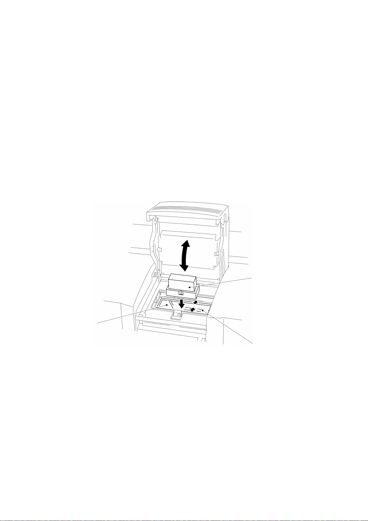
2.19 Reassembly of the Xenon Unit Assy
Insert the xenon unit assy into the machine at its right side, as shown in Fig. 3.98.
Note: Insert the xenon unit assy all the way until it is locked.
Fig. 3.98
Body cover
Xenon unit assy
III - 78
 Loading...