

Page 1
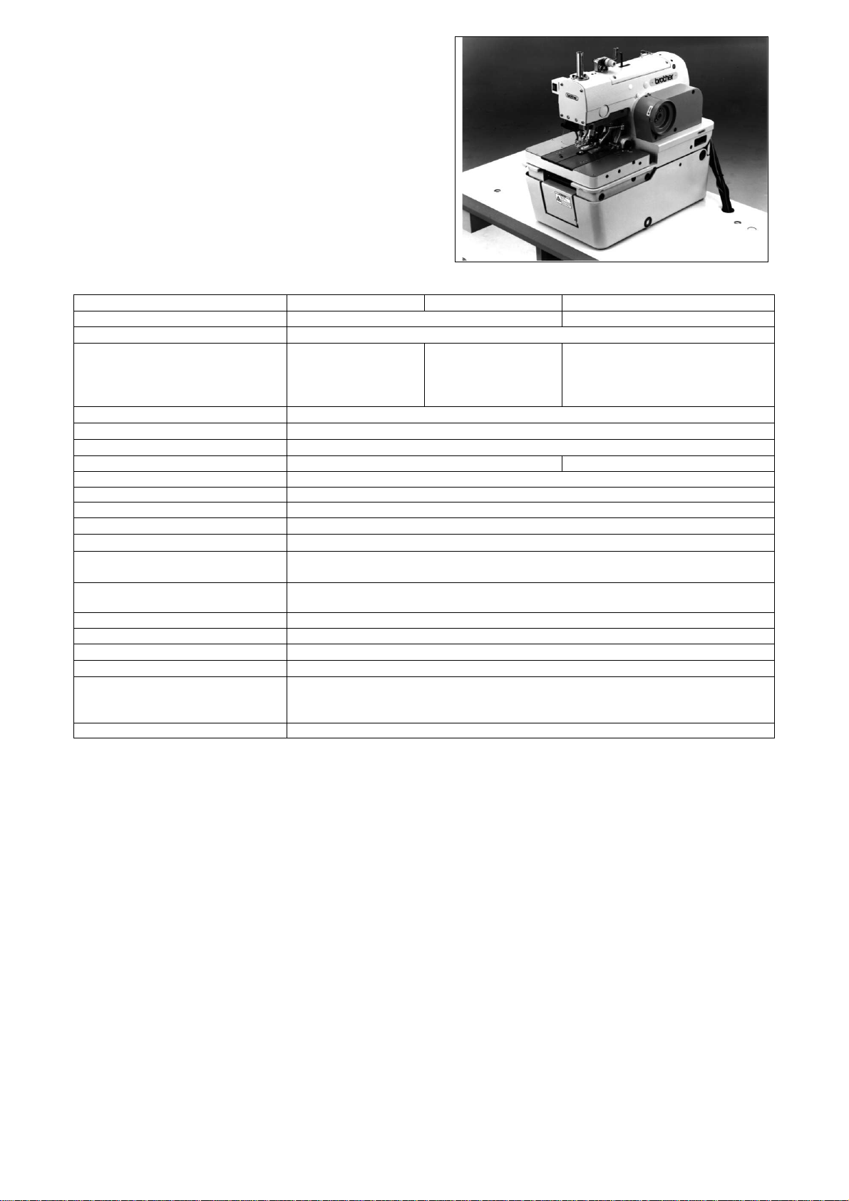
RH−9800
Electronic Eyelet Button Holer
Specifications
Specifications
Main use Men’s clothes and ladies’ clothes Jeans and work clothes
Sewing speed
Buttonhole length
Stitch length
Stitch width
Tacking length
Cloth presser height 12 mm 16 mm
Stitch shape changing Selected by a program
Cut timing selection Selected by a switch
Starting method Dual switch (cloth presser switch and start switch) or single switch
Feed method
Needle
Safety equipment
Air pressure
Air consumption 43.2 l / min (8 cycle / min)
Noise level 81 dB at max. speed of 2,000 rpm, measured according to ISO 10821
Dimensions
Work table legs
Power supply
Weight 175 kg
Built−in emergency stop function and automatic stopping device which stops the machine
−00 −01 −02
1,000−2,000 rpm (100−rpm steps)
10 − 50mm 10 − 38 mm
0.5 − 2.0 mm (0.1 mm steps)
1.5 − 3.2 mm
0 mm, 3 − 43 mm (1 mm steps)
Intermittent feed by three pulse motors (X, Y, θ)
DO × 558 #80 − #120 (Schumetz)
when the safety circuit is activated.
Main regulator: 0.49 Mpa
Knife pressure regulator: 0.3 Mpa
1,200 mm (W) × 590 mm (D) × 1,120 mm (H)
T−shaped height−adjustable type
Single−phase 110, 200, 220, 230, 240 V
Three phase 220, 380, 415 V
Max. electric power consumption: 1kVA
L1: 14 − 18 mm L5: 28 − 32 mm
L2: 18 − 22 mm L6: 32 − 36 mm
L3: 22 − 26 mm L7: 36 − 40 mm
L4: 26 − 30 mm
2002.10
RH-9800 1/17
Page 2
Device for each sub-class
RH−−−−9800−−−−
Upper
thread
trimmer
00
01
Standard bar tacking
02 {
/ eyelet buttonhole
03 {
with taper bar
04 {{
05
12
Straight bar tacking
15
Eyelet button hole
52
with taper bar
55
(with fly indexer)
Lower thread
trimmer
Long Short
{
{{
{
{
{
{
{
−−
{*1 Option Option
−
−−
{*1 { Option
−
{*1 Option
−
{*1
−
{*1 Option
−
{*1
−
Upper
thread
nipper*2
Option*2
Option*2
−
{
−
{
{
{{
Fly indexer Upper
−
−
−−−− −
−−−− −
−−−− −
−−−− −
{
gimp guide
Option*2 Option Option Option *3
Option*2 Option Option Option *3
−−− −
−−− −
−−− −
−−− −
Circular
stitching
buttonhole
set
Round bar
tacking set
*1 If using the lower thread trimmer (short type), please specify the buttonhole length when ordering.
There is 10 mm of difference in the knife installation positions between L1 − L4 and L5 − L7.
*2 The upper thread nipper cannot be used in conjunction with the upper gimp guide.
*3 The special lapel cutting device can be used only when the feed bracket is set to the front position.
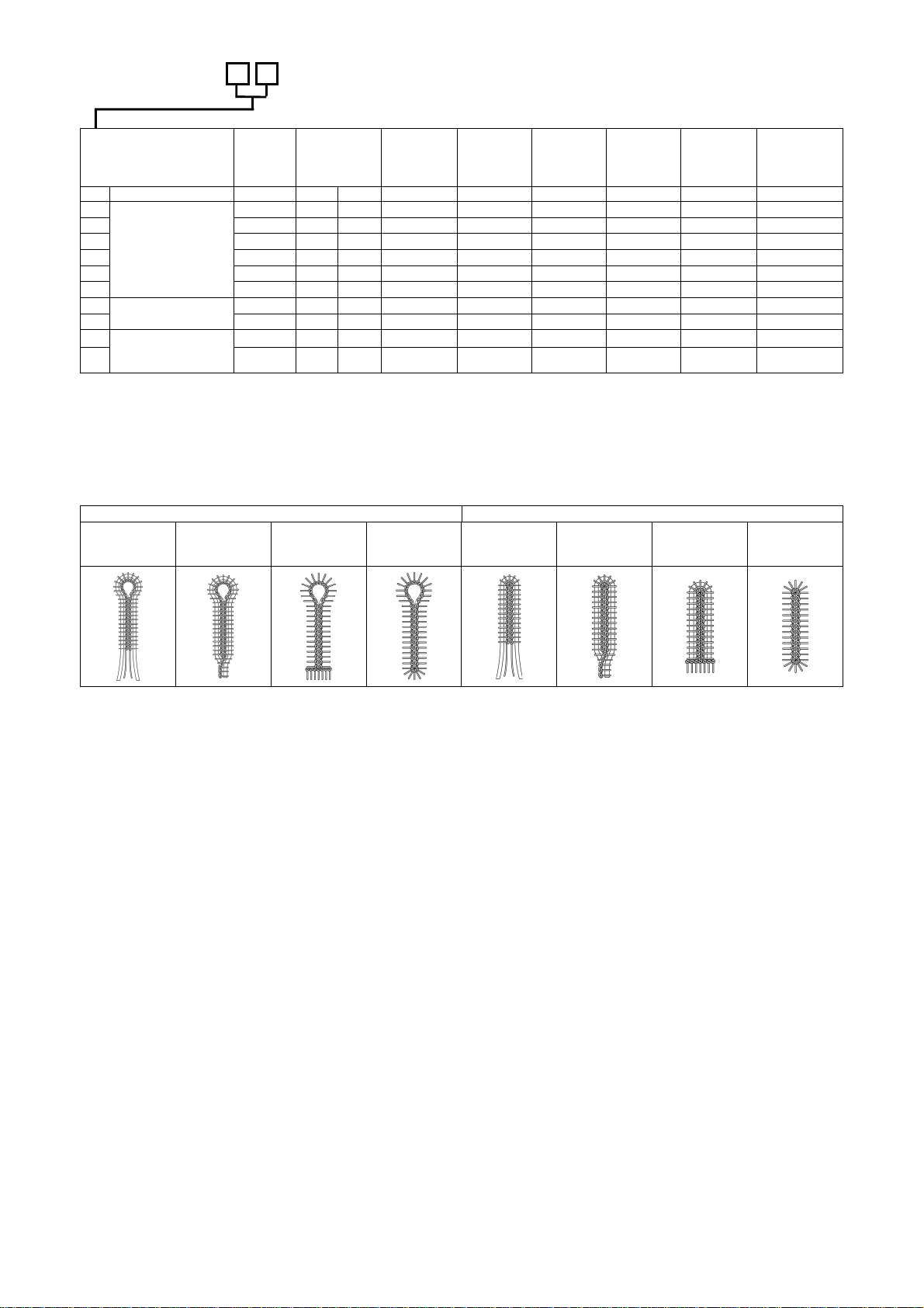
Sewing shape
Eyelet
buttonhole
Eyelet buttonhole Straight buttonhole
Eyelet
Buttonhole
with taper
With straight
bar tack
With round
bar tack
Straight
buttonhole
Straight
buttonhole with
taper
With straight
bar tack
Special lapel
cutting device
With round bar
tack
RH-9800 2/17
2002.10
Page 3
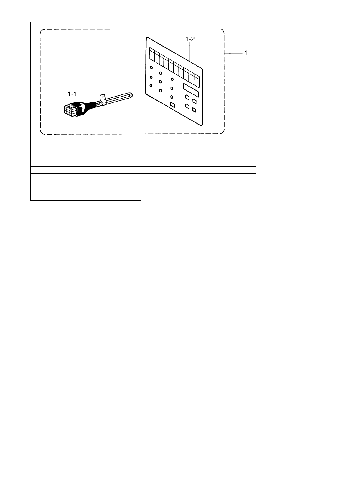
Round bar tacker set
Ref. No. Part name
1 Round bar tacker set S45195-000
1-1 Harness S44954-000
1-2 Panel sheet S44953-000
Pressers Buttonhole length Pressers Buttonhole length
L1
L2
L3
L4
16 − 19 mm
20 − 23 mm
24 − 27 mm
28 − 31 mm
L5
L6
L7
Part code
30 − 33 mm
34 − 37 mm
38 − 41 mm
*When a short thread trimmer is attached, each presser is designated as L1−L4 according to the stitch length. Use
the appropriate presser as per the table above.
2002.10
RH-9800 3/17
Page 4
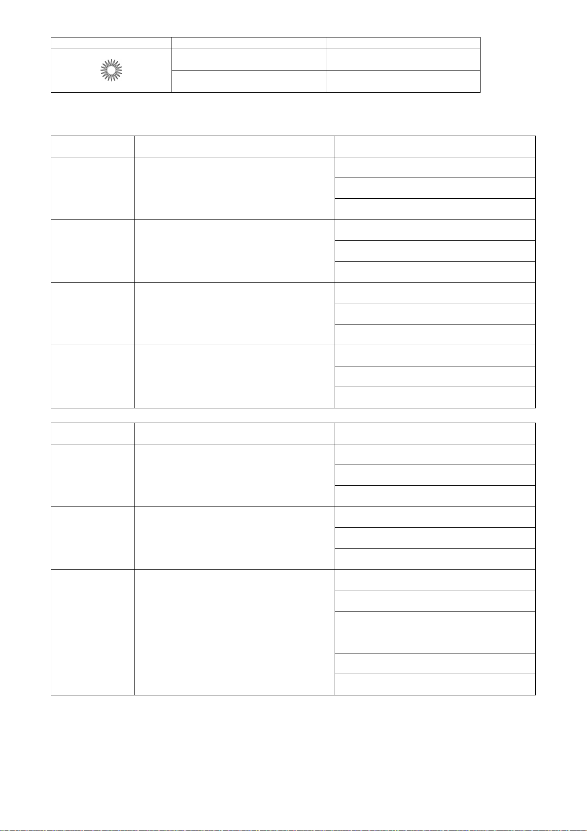
Circular stitching set
Sewing shape Outer diameter of circular stitching Presser harness
−10 mm −
Presser harness D13
Exchange parts set
– 00 用用用用 / For – 00
Stitching diameter
(mm)
2
3
4
5
For – 01
Stitching diameter
(mm)
2
3
4
5
−12 mm
Parts set
Exchange parts set D2 (-00)
S42174-001
Exchange parts set D3 (-00)
S41998-001
Exchange parts set D4 (-00)
S42175-001
Exchange parts set D5 (-00)
S41999-001
Parts set
Exchange parts set D2 (-01)
S42176-001
Exchange parts set D3 (-01)
S42000-001
Exchange parts set D4 (-01)
S42177-001
Exchange parts set D5 (-01)
S42001-001
S41506−000
Contents
Cloth presser set D11 (-00)
S43934-001
Knife (D2)
S41346-001
Hammer (D3)
S41344-001
Cloth presser set D11 (-00)
S43934-001
Knife (D3)
S41347-001
Hammer (D3)
S41344-001
Cloth presser set D13 (-00)
S43935-001
Knife (D4)
S41348-001
Hammer (D5)
S41345-001
Cloth presser set D13 (-00)
S43935-001
Knife (D5)
S41349-001
Hammer (D5)
S41345-001
Contents
Cloth presser set D11 (-01)
S43936-001
Knife (D2)
S41346-001
Hammer (D3)
S41344-001
Cloth presser set D11 (-01)
S43936-001
Knife (D3)
S41347-001
Hammer (D3)
S41344-001
Cloth presser set D13 (-01)
S43937-001
Knife (D4)
S41348-001
Hammer (D5)
S41345-001
Cloth presser set D13 (-01)
S43937-001
Knife (D5)
S41349-001
Hammer (D5)
S41345-001
RH-9800 4/17
2002.10
Page 5
Option parts
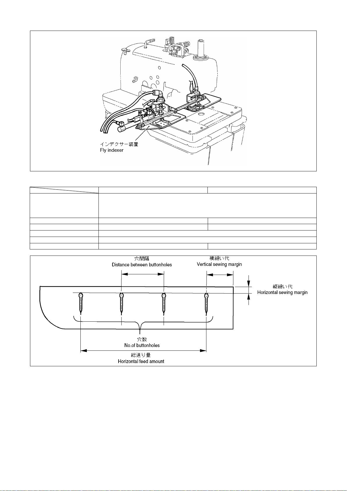
Fly indexer
Specifications
L1 (Buttonhole length : 14 - 18 mm), L5 (Buttonhole length : 28 - 32 mm)
Applicable specifications
Distance between button holes
No. of buttonholes
Horizontal sewing margin
Vertical sewing margin
Max. horizontal feed amount
L2 (Buttonhole length : 18 - 22 mm), L6 (Buttonhole length : 32 - 36 mm)
L3 (Buttonhole length : 22 - 26 mm), L7 (Buttonhole length : 36 - 40 mm)
L4 (Buttonhole length : 26 - 30 mm)
Standard size
38.1 mm, 50.8 mm, 44.45 mm
1 - 4 holes
(L1 - L4) 9 - 21 mm, (L5 - L7) 9 - 11 mm
152.4 mm
30 - 40 mm
38.1 mm, 50.8 mm, 44.45 mm, 57.15 mm
Large size
1 - 6 holes
285.75 mm
2002.10
RH-9800 5/17
Page 6

Parts for the standard-sized fly indexer (Conventional parts)
Part name
Fly indexer assy
*If the standard-sized fly indexer is used for sewing with a non-standard distance between buttonholes and a non-standard number of
buttonholes (up to 9), you need to make additional holes in the cloth feed bar (F) assy (optional part). For this processing, refer to the
instruction manual supplied with this optional part.
Part code
S42168-101
S42169-101
S42110-101
S42170-101
Applicable specifications
For L1, L2, L5
For L3, L4, L6, L7
Remarks
Without upper thread nipper
With upper thread nipper
Without upper thread nipper
With upper thread nipper
Part name
Cloth feed bar (F) assy (L1, L2)
Cloth feed bar (F) assy (L3, L4)
Part code
S45193-101
S45194-101
Applicable specifications
L1, L2, L5
L3, L4, L6, L7
Parts for the large-sized fly indexer
Part name
Fly indexer (LS) assy S48329-101 L1, L2, L5
Fly indexer (LL) assy S48334-101 L3, L4, L6, L7
Part code
Applicable specifications
*There are only four types of the distances between buttonholes for large−sized fly indexer.
Remarks
Without upper thread nipper
RH-9800 6/17
2002.10
Page 7

Option parts
Upper thread nipper
Thread nipper device set
Part name Part code Q’ty
S43406−301
1
2002.10
RH-9800 7/17
Page 8

Option parts
Gimp device
Parts set
Upper gimp guide set
S42656-001
Contents
Upper gimp guide set
S44503-001
Cotton stand assy, 4DTHF
S29854-109
RH-9800 8/17
2002.10
Page 9

Option parts
Hand start switch
Ref. No. Part name Part code Q’ty
1 Hand start switch assy
1−1
1−2
1−3
1−4
1−5
1−6
1−7
1−8
1−9
1−10
1−11 Screw, bind M3 × 6 060300−616
1−12
1−13 Screw, bind M4 × 8 060400−816
Switch set plate
Switch lever spring
Hand switch
Switch cover
Switch lever (L)
Switch lever (R)
Stud screw, M4
Stud screw, M4
Nut, 2M4
Screw, M2.38
Band PLTIM
S39909−001
S39913−001
S39914−001
S39915−000
S39910−001
S39911−001
S39912−001
S34922−101
S34966−001
012400−202
146124−001
S04557−000
1
1
1
1
1
1
1
1
2
3
2
2
1
2
2002.10
RH-9800 9/17
Page 10

Special lapel cutting device
*When sewing straight buttonholes, needle rotates 6 mm in front of the tip of the eyelet buttonhole knife, so that the
seam length for straight buttonholes will be as shown in the table.
*The standard hammers are 5 mm and 7 mm.
*The special lapel cutting device can be used only when the feed bracket is set to the front position.
Specifications Eyelet buttonhole Straight buttonhole
RH-9800-00 10 – 50 mm 10 – 44 mm
RH-9800-01 10 – 38 mm 10 – 32 mm
RH-981A-00 5 – 50 mm 5 – 44 mm
RH-981A-01 5 – 38 mm 5 – 32 mm
RH-9800 10/17
2002.10
Page 11

Ref. No. Part name Part code Q’ty
15 Special lapel cutting device S53906-101 1
15-1 Selector assy, hammer S53907-001 1
15-1-1 Support plate, cylinder S53908-001 1
15-1-2 Setting plate, cylinder S53909-001 1
15-1-3 Bolt, socket SM3.57x8 154965-001 2
15-1-4 Washer, plain 105161-004 2
15-1-5 Screw, pan M3x6 062300-605 2
15-1-6 Setting lever, hammer S53910-001 1
15-1-7 Bolt, socket SM3.57x8 154965-001 1
15-1-8 Partition plate, sensor S53914-001 1
15-1-9 Set screw, SM3.57-40x4.5 144458-001 1
15-1-10 Sensor, hammer home position S53915-000 1
15-1-11 Sensor, hammer position S53916-000 1
15-1-12 Sensor bracket, MS-GL8 S53917-000 2
15-1-13 Screw, pan M3x8 062300-805 2
15-1-15 Rotary cylinder assy S53918-001 1
15-1-1 Rotary cylinder plate assy S54026-001 1
15-1-15-1-1 Setting plate, sensor S53913-001 1
15-1-15-1-2 Bolt, socket M3x16 018301-636 2
15-1-15-2 Throttle tube joint S19900-000 1
15-1-16 Tube elbow, w/valve S16603-000 1
15-1-17 Air tube, 4x2.5-60 S53920-000 1
15-1-18 Air tube, 4x2.5-61 S53921-000 1
15-2 Band, PLT1M S04557-000 1
15-2- Sensor plate assy, B-hole S53923-001 1
15-2-1 Setting plate, cloth sensor S53924-001 1
15-2-2 Y-driving shaft holder S31568-000 1
15-2-3 Bolt, socket M5x16 018501-622 1
15-2-4 Bolt, socket SM4.37x8 018680-822 2
15-2-5 Washer 100645-003 2
15-2-6 Photo sensor S53925-000 1
15-2-7 Screw, pan (S/P washer) M3x8 0A4300-805 2
15-2-8 Harness, B-hole sensor S53926-000 1
15-2-9 Band, PLT1M S04557-000 1
15-3 Setting shaft, sensor S53922-001 1
15-4 Valve assy S53927-000 1
15-4-1 Valve, VZ3120-F S53928-001 1
15-4-1-1 Valve, VZ3120 S13578-000 1
15-4-1-2 Bracket S53929-000 1
15-4-2 Half union S04905-000 1
15-4-3 Elbow union, 4M5 S11426-000 2
15-5 Wood screw, round M3.5x16 032361-602 2
15-6 Valve harness S53930-000 1
15-7 Hammer plate, 7 S53911-001 1
15-8 Bolt, socket M3x5 018300-536 2
15-9 Bolt, socket M4x8 018400-832 2
15-10 Cord holder, 6N 146202-000 1
15-11 Screw, pan M4x16 062401-616 1
15-12 Washer, plain M6 025060-236 1
15-13 Band, PLT1M S04557-000 3
15-14 Half union, ;KQH04-01S S04910-000 1
15-15 Air tube, 4x2.5-62 S53939-000 1
15-16 Cover, H ;N-rotation S53937-001 1
15-17 Cord holder, 10N 552907-000 1
16 Hammer plate, 5 S53912-001 1
2002.10
RH-9800 11/17
Page 12

Option parts
Cloth guide
Part name Part code Q’ty
Cloth guide, J S37870-000 1
Movable knife cover
Ref. No. Part name Part code Q’ty
<L1, L2, L5, L6>
1 Movable knife cover, L1-2 S37698-000 1
<L3, L4, L7>
2 Movable knife cover, L3-4 S37699-000 1
For changing to –02 from –01
Replace with the parts shown in the table below.
L1: 14 - 18 mm L2: 18 - 22 mm L3: 22 - 26 mm L4: 26 - 30 mm
S38572-001 S38573-001 S38574-001 S38575-001
Exchange parts set, L1 Exchange parts set, L2 Exchange parts set, L3 Exchange parts set, L4
S38584-001
Exchange parts set, -2
L2: 28 - 32 mm L3: 32 - 36 mm L4: 36 - 40 mm
S41467-00 S41468-001 S41469-001
Exchange parts set, L5 Exchange parts set, L6 Exchange parts set, L7
S38584-001
Exchange parts set, -2
RH-9800 12/17
2002.10
Page 13

Replacement parts list for specification changes
The sewing machine can be changed to any one of L1 to L7 for –02 and –52 specifications by replacing the specified
parts with the appropriate parts given below.
-02 specifications
Plate R assemblySpecifications
Plate L assembly
S38576-301 S37702-001 (S12)L1
S38577-201 S37704-001 (S16)
S38578-301 S37704-001 (S16)L2
S38579-201 S37706-001 (S20)
S38580-301 S37706-001 (S20)L3
S38581-201 S37708-001 (S24)
S38582-301 S37708-001 (S24)L4
S38583-201 S42053-001 (S28)
S41470-101 S37197-001 (26)L5
S41471-101 S37199-001 (30)
S41472-101 S37199-001 (30)L6
S41473-101 S37201-001 (34)
S41474-101 S37201-001 (34)L7
S41475-101 S35093-001 (38)
Hammer Specification harness
S37869-100
S37871-000
S37872-100
S37873-000
S41476-000
S41477-000
S41478-000
(buttonhole length)
(14 - 18mm)
(18 - 22mm)
(22 - 26mm)
(26 - 30mm)
(28 - 32mm)
(32 - 36mm)
(36 - 40mm)
Replacement parts set
S38572-001
S38573-001
S38574-001
S38575-001
S41467-001
S41468-001
S41469-001
Note: There is 10 mm of difference in the knife cutting position between L1 – L4 and L5 – L7 specifications.
-52 specifications
Specifications
(buttonhole length)
L1
(14 - 18mm)
L2
(18 - 22mm)
L3
(22 - 26mm)
L4
(26 - 30mm)
L5
(28 - 32mm)
L6
(32 - 36mm)
L7
(36 - 40mm)
Note: There is 10 mm of difference in the knife cutting position between L1 – L4 and L5 – L7 specifications.
Plate R assembly
Plate L assembly
S38576-301 S37702-001(S12)
S38577-201
S38578-301 S37704-001(S16)
S38579-201
S38580-301 S37706-001(S20)
S38581-201
S38582-301 S37708-001(S24)
S38583-201
S41470-101 S37197-001(26)
S41471-101
S41472-101 S37199-001(30)
S41473-101
S41474-101 S37201-001(34)
S41475-101
Hammer Cloth feed plate R
S37704-001(S16)
S37706-001(S20)
S37708-001(S24)
S42053-001(S28)
S37199-001(30)
S37201-001(34)
S35093-001(38)
S43809-001
S43809-001
S42139-101
S42139-101
S43809-001
S42139-101
S42139-101
2002.10
RH-9800 13/17
Page 14

Gauge parts list
(For -00, -01, -02) Work clamp
L
R
S35455−001 S39929−001 S35197−001 S39931−001
S35454−001 S39930−001 S35198−001 S39932−001
<10 − 18 mm> <18 − 22 mm> <22 − 26 mm> <26 − 30 mm>
−00
&
−01
L
R
−02
S35453−001 S35200−101 S37679−001 S37677−101
S35452−001 S35199−101 S37680−001 S37678−101
<26 − 38 mm>
S37755−001 S37689−001 S37691−001 S37759−001
S37754−001 S37690−001 S37692−001 S37758−001
L1 <14 − 18 mm> L2 <18 − 22 mm> L3 <22 − 26 mm> L4 <26 − 30 mm>
S41848-001 S41486-101 S41488-001 S43408-001 S43410-001
S41483-001 S41485-101 S41487-001 S43409-001 S43411-001
L5 <28 − 32 mm>
L6 <32 − 36 mm> L7 <36 − 40 mm>
<38 mm> <50 mm> <50 mm>
L3W <22 − 26 mm> L4W <26 − 30 mm>
For circular stitching work clamp
R & L
−00
&
−01
S41336−001 S41337−001
D11 < − 10 mm>
D13 < − 12 mm>
<For waist belt presser>
RH-9800 14/17
2002.10
Page 15

Gauge parts list
Needle plate
L
R
−00
&
−01
S35308−101 (L) S35307−101 (SL) S37683−101 (L−50) S37681−101 (SL−50)
S35309−101 (R) S35306−101 (SR) S37684−101 (R−50) S37682−101 (SR−50)
<38 mm>
<38 mm> <50 mm> <50 mm>
L
R
−02
S37643−101 (L1L) S37645−101 (L2L) S37647−101 (L3L) S37649−101 (L4L)
S37644−101 (L1R) S37646−101 (L2R) S37648−101 (L3R) S37650−101 (L4R)
L1 <14 − 18 mm> L2 <18 − 22 mm> L3 <22 − 26 mm> L4 <26 − 30mm>
S40823-001 (L5L) S41480-001 (L6L) S41482-001 (L7L)
S40822-001 (L5R) S41479-001 (L6R) S41481-001(L7R)
L5 <28 − 32 mm>
L6 <32 − 36 mm> L7 <36 − 40 mm>
For circular stitching needle plate
L S41339-001 S41341-001
R S41338-001 S41340-000
D11 < − 10 mm>
D13 < − 12 mm>
−00
&
−01
RH-9800 15/17
2002.10
Page 16

Gauge parts list
Knife
S35439−101 S35437−101 S35480−101 S35482−101 S35408−101 (S)
<38 mm> <38 mm> <38 mm> <38 mm> <38 mm>
S35438−101 S35436−101 S35481−101 S35483−101 S35409−101 (S)
<50 mm> <50 mm> <50 mm> <50 mm> <50 mm>
For circular stitching knife
S41346-001 S41347-001 S41348-001 S41349-001
<D2> <D3> <D4> <D5>
Hammer
Size (mm) 10 12 14 16
−00
&
−01
−02
Part code
Size (mm) 18 20 22 24
Part code
Size (mm) 26 28 30 32
Part code
Size (mm) 34 36 38 50
Part code
Size (mm) S10 S12 S14 S16
Part code
Size (mm) S18 S20 S22 S24
Part code
Size (mm) S26 S28
Part code
S37211−001 S37210−001 S37209−001 S37208−001
S37194−001 S35092−001 S37195−001 S37196−001
S37197−001 S37198−001 S37199−001 S37200−001
S37201−001 S37202−001 S35093−001 S35479−001
S37701−001 S37702−001 S37703−001 S37704−001
S37705−001 S37706−001 S37707−001 S37708−001
S37709−001
For circular stitching hammer
−00 & −01
Size (mm)
Part code
φ5 (D2, D3) φ7 (D4, D5)
S41344−001 S41345−001
Harness
SpecificationL1L2L3L4
-02
Part code S37869-100 S37871-000 S37872-100 S37873-000
Specification L5 L6 L7
Part code S41476-000 S41477-000 S41478-000
S42053-001
RH-9800 16/17
2002.10
Page 17

Gauge parts list
Double chain stitch looper mechanism
Eye Looper
Use
Looper, R
Spreader, L
Spreader, R
Standard
For heavy
For single chain stitch
S35411-001
S35471-001
S49078-001
S35410-001
Throat plate
Throat plate
Use
For -00 and -01 A = 1.8 mm B = 4.6 mm
For -00 and -01 (For small hole) A = 1.8 mm B = 4.6 mm
For -02 A = 1.8 mm B = 4.6 mm
For straight bar tack A = --------- B = 4.6 mm
S47033-001
S47034-001
S37752-001
S39923-101
S35413-101
S35472-101
S49079-001
S35412-101
2002.10
RH-9800 17/17
 Loading...