


MULTI-FUNCTION CENTER
SERVICE MANUAL
MODEL: MFC9600/MFC9850/MFC9870
DCP1200/MFC9750

© Copyright Brother 2000
All rights reserved.
No part of this publication may be reproduced in any form or by any means without permission in writing
from the publisher.
Specifications are subject to change without notice.
All products and company names mentioned in this manual are trademarks or registered trademarks of their
respective holders.

PREFACE
This publication is a Service Manual covering the specifications, construction, theory of operation,
and maintenance of the Brother machine. It includes information required for field troubleshooting
and repair--disassembly, reassembly, and lubrication--so that service personnel will be able to
understand machine function, to rapidly repair the machine and order any necessary spare parts.
To perform appropriate maintenance so that the machine is always in best condition for the
customer, the service personnel must adequately understand and apply this manual.
This manual is made up of six chapters and appendices.
CHAPTER I. GENERAL DESCRIPTION
CHAPTER II. INSTALLATION
CHAPTER III. THEORY OF OPERATION
CHAPTER IV. DISASSEMBLY/REASSEMBLY AND LUBRICATION
CHAPTER V. MAINTENANCE MODE
CHAPTER VI. ERROR INDICATION AND TROUBLESHOOTING
Appendix 1. EEPROM Customizing Codes
Appendix 2. Circuit Diagrams
This manual describes the models and their versions to be destined for major countries. The specifications
and functions are subject to change depending upon each destination.

SAFETY INFORMATION
Laser Safety (110-120V Model only)
This printer is certified as a Class 1 laser product under the US Department of Health and Human
Services (DHHS) Radiation Performance Standard according to the Radiation Control for Health
and Safety Act of 1968. This means that the printer does not produce hazardous laser radiation.
Since radiation emitted inside the printer is completely confined within the protective housings and
external covers, the laser beam cannot escape from the machine during any phase of user
operation.
CDRH Regulations (110-120V Model only)
The Center for Device and Radiological Health (CDRH) of the US Food and Drug Administration
implemented regulations for laser products on August 2, 1976. These regulations apply to laser
products manufactured from August 1, 1976. Compliance is mandatory for products marketed in
the United States. The label shown below indicates compliance with the CDRH regulations and
must be attached to laser products marketed in the United States.
The label for Chinese products
MANUFACTURED: JULY 1999 C
BROTHER CORP. (ASIA) LTD.
BROTHER BUJI NAN LING FACTORY
Gold Garden Industry, Nan Ling Village, Buji,
Rong Gang, Shenzhen, China.
This product complies with FDA radiation
performance standards, 21 CFR Subchapter J.

CHAPTER I.
GENERAL DESCRIPTION

CHAPTER I. GENERAL DESCRIPTION
CONTENTS
1. MACHINE OUTLINE.............................................................................................I-1
1.1External Appearance and Weight.................................................................I-1
1.2Components.................................................................................................I-1
2. SPECIFICATIONS................................................................................................I-2
1. MACHINE OUTLINE
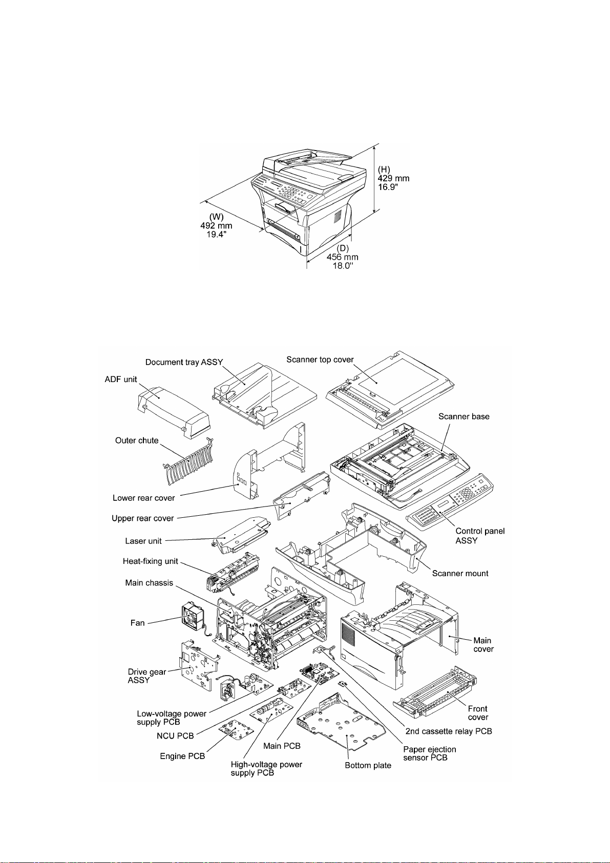
1.1 External Appearance and Weight
The figure below shows the machine appearance and approximate dimensions.
Weight: Machine proper 15.2 kg
Machine (incl. drum unit & toner cartridge) 17.0 kg
In package 21.2 kg
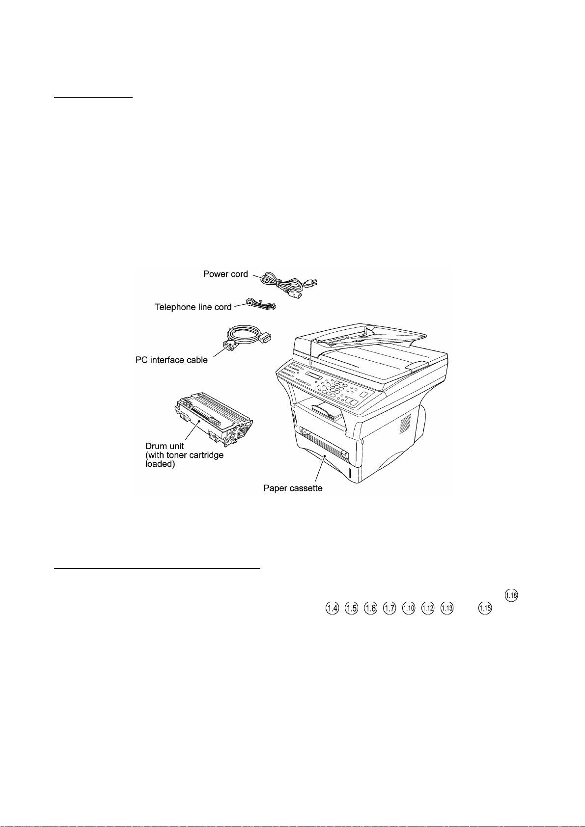
1.2 Components
The machine consists of the following major components:
I - 1

2. SPECIFICATIONS
Machine Type Multi-Function Center w/ Fax Multi-Function Center w/o Fax
Model MFC9600 DCP1200
GENERAL
Print Engine Laser (ZL) Laser (ZL)
Modem Speed (bps) 14,400 (Fax)
Transmission Speed (sec.) 5
ITU-T Group G3
Coding System MH/MR/MMR/JBIG
Input/Output Width FB: 8.5" x 11"
ADF: 5.8" to 8.5"/2.75" to 8.5"
ADF (pages) Up to 50 Up to 50
LCD 16 chars x 2 lines 16 chars x 2 lines
On-Screen Programming Yes Yes
Backup Clock Yes (1 hour) Yes (1 hour)
Memory Capacity 8 MB 8 MB
Backup Memory No No
Optional Memory Yes (8 & 16 MB) Yes (8 & 16 MB)
Dimensions w/ Carton (WxDxH) 23.5 x 22.3 x 22.8 inches
598 x 567 x 580 mm
Dimensions w/o Carton (WxDxH) 19.4x18x16.9 inches
492x456x429 mm
Weight w/o Carton 17 kg 17 kg
Weight w/ Carton 21.2 kg 21.2 kg
Color Gray 1495 Gray 1495
Standby Mode Yes Yes
PC-Fax Protocol Compliance Class 2
Simultaneous Operation Yes (Print/Fax, Print/Copy, Print/Scan) Yes (Print/Copy, Print/Scan)
Energy Star Compliance Yes Yes
Operating Environment
Temperature
Humidity
Power Source 120 VAC, 50/60 Hz 120 VAC, 50/60 Hz
Power Consumption
(Sleep/Standby/Peak)
On/Off Switch No Yes
TELEPHONE No
Automatic Redial Yes
Handset No
One-Touch Dial 32 (16x2)
Speed Dial 100
Max. Number of Digits for One-
Touch & Speed Dial
Registerable Number Of
Characters
Telephone Index Yes (Normal)
Speaker Phone No (Only On-HOOK/Monitor Available)
Less than 14W/60W/850W Less than 14W/60W/850W
5°C to 35°C
60% ±25%
20 digits
15 chars
ADF: 5.8" to 8.5"/2.75" to 8.5"
FB: 8.5" x 11"
23.5 x 22.3 x 22.8 inches
598 x 567 x 580 mm
19.4x18x16.9 inches
492x456x429 mm
5°C to 35°C
60% ±25%
(1/6)
I - 2

(1/6)
Machine Type Multi-Function Center w/ Fax Multi-Function Center w/ Fax
Model MFC9870 MFC9850
GENERAL
Print Engine Laser (ZL) Laser (ZL)
Modem Speed (bps) 14,400 (Fax) 14,400 (Fax)
Transmission Speed (sec.) 5 5
ITU-T Group G3 G3
Coding System MH/MR/MMR/JBIG MH/MR/MMR/JBIG
Input/Output Width FB: 8.5" x 11"
ADF: 5.8" to 8.5"/2.75" to 8.5"
ADF (pages) Up to 50 Up to 50
LCD 16 chars x 2 lines 16 chars x 2 lines
On-Screen Programming Yes Yes
Backup Clock Yes (9 hours) Yes (9 hours)
Memory Capacity 4 MB (RAM) + 4 MB (flash ROM) 4 MB (RAM) + 2 MB (flash ROM)
Backup Memory 2 MB (flash ROM) 2 MB (flash ROM)
Optional Memory Yes (RAM: 8 & 16 MB, ROM: 4 & 2 MB) Yes (RAM: 8 & 16 MB)
Dimensions w/ Carton (WxDxH) 23.5 x 22.3 x 22.8 inches
598 x 567 x 580 mm
Dimensions w/o Carton (WxDxH) 19.4x18x16.9 inches
492x456x429 mm
Weight w/o Carton 17 kg 17 kg
Weight w/ Carton 21.2 kg 21.2 kg
Color Gray 1495 Gray 1495
Standby Mode Yes Yes
PC-Fax Protocol Compliance Class 2
Simultaneous Operation Yes (Print/Fax, Print/Copy, Print/Scan) Yes (Print/Fax, Print/Copy, Print/Scan)
Energy Star Compliance Yes Yes
Operating Environment
Temperature
Humidity
Power Source 220 VAC, 50/60 Hz 220 VAC, 50/60 Hz
Power Consumption
(Sleep/Standby/Peak)
On/Off Switch No No
TELEPHONE
Automatic Redial Yes Yes
Handset No No
One-Touch Dial 32 (16x2) 32 (16x2)
Speed Dial 100 100
Max. Number of Digits for One-
Touch & Speed Dial
Registerable Number Of
Characters
Telephone Index Yes (Normal) Yes (Normal)
Speaker Phone No No
Less than 14W/60W/800W Less than 14W/60W/800W
5°C to 35°C
60% ±25%
20 digits 20 digits
15 chars 15 chars
ADF: 5.8" to 8.5"/2.75" to 8.5"
FB: 8.5" x 11"
23.5 x 22.3 x 22.8 inches
598 x 567 x 580 mm
19.4x18x16.9 inches
492x456x429 mm
5°C to 35°C
60% ±25%
I - 3

Machine Type Multi-Function Center w/o Fax
Model MFC9750
GENERAL
Print Engine Laser (ZL)
Modem Speed (bps)
Transmission Speed (sec.)
ITU-T Group
Coding System
Input/Output Width FB: 8.5" x 11"
ADF: 5.8" to 8.5"/2.75" to 8.5"
ADF (pages) Up to 50
LCD 16 chars x 2 lines
On-Screen Programming Yes
Backup Clock No
Memory Capacity 4 MB (RAM)
Backup Memory No
Optional Memory Yes (RAM: 8 & 16 MB)
Dimensions w/ Carton (WxDxH) 23.5 x 22.3 x 22.8 inches
598 x 567 x 580 mm
Dimensions w/o Carton (WxDxH) 19.4x18x16.9 inches
492x456x429 mm
Weight w/o Carton 17 kg
Weight w/ Carton 21.2 kg
Color Gray 1495
Standby Mode Yes
PC-Fax Protocol Compliance
Simultaneous Operation Yes (Print/Copy, Print/Scan)
Energy Star Compliance Yes
Operating Environment
Temperature
Humidity
Power Source 220 VAC, 50/60 Hz
Power Consumption
(Sleep/Standby/Peak)
Less than 14W/60W/800W
5°C to 35°C
60% ±25%
(1/6)
TELEPHONE No
Automatic Redial
Handset
One-Touch Dial
Speed Dial
Max. Number of Digits for One-
Touch & Speed Dial
Registerable Number Of
Characters
Telephone Index
Speaker Phone
I - 4

Machine Type Multi-Function Center w/ Fax Multi-Function Center w/o Fax
Model MFC9600 DCP1200
Chain Dialing Yes
Caller ID Yes
Call Waiting Caller ID No
Distinctive Ringing Yes
Hold/Mute Key No
Power Failure Dialing No
Speaker Volume Yes (3 steps + OFF)
Ringer Volume Yes (3 steps + OFF)
Handset Volume No
PBX Feature No
Transfer Method Flash
FAX No
Internet FAX Yes (Network/PC) LAN, NetCentric Yes (Network/PC), NetCentric
Data Modem No
Easy Receive/Fax Detect Yes
Fax/Tel Switch No
Super Fine Yes (TX & RX)
300 dpi Transmission No
Gray Scale 64
Contrast Yes (Auto/S.Light/S.Dark)
Smoothing Yes
Call Reservation Over Auto TX No
Password Check No
Enhanced Remote Activation Yes
Multi-Resolution Transmission Yes
Multi-Transmission No
Next-Fax Reservation Yes (Dual Access)
Delayed Timer Yes (50 timers/50 jobs)
Polling Yes (Std/Seq)
Quick-Scan Key (Memory TX w/o key)
Scan Speed (A4:Standard) Approx. 2 sec./page (A4:standard)
Memory Transmission 700 pages
Broadcasting Yes (182 locations)
Batch Transmission Yes
Auto Reduction Yes
Out-of-Paper Reception
(Brother #1 Chart)
Dual Access Yes
ECM (Error Correction Mode) Yes
ITU SUB Addressing No
Up to 310 pages
(2/6)
I - 5

Machine Type Multi-Function Center w/ Fax Multi-Function Center w/ Fax
Model MFC9870 MFC9850
Chain Dialing Yes Yes
Caller ID No No
Call Waiting Caller ID No No
Distinctive Ringing Yes (U.K. DEN) Yes (U.K. DEN)
Hold/Mute Key No No
Power Failure Dialing No No
Speaker Volume Yes (3 steps + OFF) Yes (3 steps + OFF)
Ringer Volume Yes (3 steps + OFF) Yes (3 steps + OFF)
Handset Volume No No
PBX Feature Yes Yes
Transfer Method Flash Flash
FAX
Internet FAX Yes (Network), available w/ option No
Data Modem No No
Easy Receive/Fax Detect Yes Yes
Fax/Tel Switch No No
Super Fine Yes (TX & RX) Yes (TX & RX)
300 dpi Transmission No No
Gray Scale 64 64
Contrast Yes (Auto/S.Light/S.Dark) Yes (Auto/S.Light/S.Dark)
Smoothing Yes Yes
Call Reservation Over Auto TX No No
Password Check No No
Enhanced Remote Activation Yes Yes
Multi-Resolution Transmission Yes Yes
Multi-Transmission No No
Next-Fax Reservation Yes (Dual Access) Yes (Dual Access)
Delayed Timer Yes (50 timers/50 jobs) Yes (50 timers/50 jobs)
Polling Yes (Std/Seq/Sec/Del) Yes (Std/Seq/Sec/Del)
Quick-Scan Key (Memory TX w/o key) (Memory TX w/o key)
Scan Speed (A4:Standard) Approx. 2 sec./page (A4:standard) Approx. 2 sec./page (A4:standard)
Memory Transmission 250 pages 250 pages
Broadcasting Yes (182 locations) Yes (182 locations)
Batch Transmission Yes Yes
Auto Reduction Yes Yes
Out-of-Paper Reception
(ITU-T Chart)
Dual Access Yes Yes
ECM (Error Correction Mode) Yes Yes
ITU SUB Addressing Yes (Wordcraft S/W) No
Up to 150 pages Up to 150 pages
(2/6)
I - 6

Machine Type Multi- Function Center w/o Fax
Model MFC9750
Chain Dialing
Caller ID
Call Waiting Caller ID
Distinctive Ringing
Hold/Mute Key
Power Failure Dialing
Speaker Volume
Ringer Volume
Handset Volume
PBX Feature
Transfer Method
FAX No
Internet FAX
Data Modem
Easy Receive/Fax Detect
Fax/Tel Switch
Super Fine
300 dpi Transmission
Gray Scale
Contrast
Smoothing
Call Reservation Over Auto TX
Password Check
Enhanced Remote Activation
Multi-Resolution Transmission
Multi-Transmission
Next-Fax Reservation
Delayed Timer
Polling
Quick-Scan Key
Scan Speed (A4:Standard)
Memory Transmission
Broadcasting
Batch Transmission
Auto Reduction
Out-of-Paper Reception
(Brother #1 Chart)
Out-of-Paper Reception
(ITU-T Chart)
Dual Access
ECM (Error Correction Mode)
ITU SUB Addressing
(2/6)
I - 7

Machine Type Multi- Function Center w/ Fax Multi- Function Center w/o Fax
Model MFC9600 DCP1200
Group Dial Yes (6)
Error Re-Transmission No
Station ID 1 (20 digits/20 chars)
Off-Hook Alarm No
Remote Maintenance Yes
Call Reservation Over Manual TX No
RX Mode Indication LCD
Resolution Indication LED
Memory Security No
Color FAX No
Manual Broadcasting Yes
LCD Language English
OPEN LCR No
E-MAIL FAX Via Net work/PC
LIST/REPORT No
Activity Report/Journal Report Yes (up to 50)
Transmission Verification Report Yes
Coverpage Yes (Super)
Help List Yes
Callback Message No
Caller ID List Yes
ALL Dial List Yes
Tel Index List Yes
(3/6)
INTERFACE
External TAD Interface Yes No
Missing Link/PC Interface No No
Host Interface (Serial) No No
Host Interface (IEEE1284) Yes Yes
Host Interface (USB) Yes Yes
LAN Interface Yes (10-Base T: LAN Board) Yes
PRINTER
Color/Mono Mono Mono
Engine Type Laser (ZL) Laser (ZL)
Resolution (dpi) 600 x 600 600 x 600
Speed (ppm) 12 12
Paper Capacity (sheets) 250 250
Additional Paper Capacity
(sheets)
Output Paper Capacity (sheets) 150 150
Standard Print Language Windows GDI (600 x 600) Windows GDI (600 x 600)
250 (User Option) 250 (User Option)
I - 8

Machine Type Multi- Function Center w/ Fax Multi- Function Center w/ Fax
Model MFC9870 MFC9850
Group Dial Yes (6) Yes (6)
Error Re-Transmission No No
Station ID 1 (20 digits/20 chars) 1 (20 digits/20 chars)
Off-Hook Alarm Yes Yes
Remote Maintenance Yes Yes
Call Reservation Over Manual TX No No
RX Mode Indication LCD LCD
Resolution Indication LED LED
Memory Security Yes Yes
Color FAX No No
Manual Broadcasting Yes Yes
LCD Language English English
OPEN LCR No No
E-MAIL FAX Yes (Via Network) No
LIST/REPORT
Activity Report/Journal Report Yes (up to 50) Yes (up to 50)
Transmission Verification Report Yes Yes
Coverpage Yes (Super) Yes (Super)
Help List Yes Yes
Callback Message No No
Caller ID List No No
ALL Dial List Yes Yes
Tel Index List Yes Yes
(3/6)
INTERFACE
External TAD Interface Yes Yes
Missing Link/PC Interface No No
Host Interface (Serial) No No
Host Interface (IEEE1284) Yes Yes
Host Interface (USB) Yes Yes
LAN Interface Yes (10-Base T: LAN Board),
PRINTER Yes Yes
Color/Mono Mono Mono
Engine Type Laser (ZL) Laser (ZL)
Resolution (dpi) 600 x 600 600 x 600
Speed (ppm) 12 12
Paper Capacity (sheets) 250 250
Additional Paper Capacity
(sheets)
Output Paper Capacity (sheets) 150 150
Standard Print Language Windows GDI (600 x 600) Windows GDI (600 x 600)
available w/ option
250 (User option) 250 (User option)
No
I - 9

Machine Type Multi- Function Center w/o Fax
Model MFC9750
Group Dial
Error Re-Transmission
Station ID
Off-Hook Alarm
Remote Maintenance
Call Reservation Over Manual TX
RX Mode Indication
Resolution Indication
Memory Security
Color FAX
Manual Broadcasting
LCD Language
OPEN LCR
E-MAIL FAX
LIST/REPORT No
Activity Report/Journal Report
Transmission Verification Report
Coverpage
Help List
Callback Message
Caller ID List
ALL Dial List
Tel Index List
(3/6)
INTERFACE
External TAD Interface No
Missing Link/PC Interface No
Host Interface (Serial) No
Host Interface (IEEE1284) Yes
Host Interface (USB) Yes
LAN Interface No
PRINTER Yes
Color/Mono Mono
Engine Type Laser (ZL)
Resolution (dpi) 600 x 600
Speed (ppm) 12
Paper Capacity (sheets) 250
Additional Paper Capacity
(sheets)
Output Paper Capacity (sheets) 150
Standard Print Language Windows GDI (600 x 600)
250 (User option)
I - 10

(4/6)
Machine Type Multi- Function Center w/ Fax Multi- Function Center w/o Fax
Model MFC9600 DCP1200
Emulation PCL4 PCL4
Resident Fonts 24 bitmap (PCL4 Comp.) 24 bitmap (PCL4 Comp.)
Fonts Disk Based Yes (35 TrueType) Yes (35 TrueType)
Paper Handling Size LTR, LGL, A4, B5, A5, A6, EXE LTR, LGL, A4, B5, A5, A6, EXE
Manual Feed Slot Custom Size (2.75" x 5" to 8.5" x 14") Custom Size (2.75" x 5" to 8.5" x 14")
Other Paper Type OHP, Envelopes, Labels, Organizer OHP, Envelopes, Labels, Organizer
Sheet Weight (Paper Cassette)
(Manual Slot)
Printer Driver Win3.1x, 95/98, and NT4.0 Driver Win3.1x, 95/98, and NT4.0 Driver
Utility Software Yes (Remote Printer Console for PCL4) Yes (Remote Printer Console for PCL4)
Bundled Cable Yes (Parallel) Yes (Parallel)
Network Optional LAN Board (Brother)
COPY
Color/Mono Mono Mono
Speed (ppm) Up to 12 Up to 12
Multi Copy (Stack) Up to 99 Up to 99
Multi Copy (Sort) Yes Yes
Reduction/Enlargement (%) 25 to 400% in 1% increments 25 to 400% in 1% increments
Resolution (dpi) 300 x 600 300 x 600
64-105 g/m2 (17 to 28 lb)
64-157 g/m2 (17 to 43 lb)
Printer/Internet FAX
64-105 g/m2 (17 to 28 lb)
64-157 g/m2 (17 to 43 lb)
Optional LAN Board (Brother) Printer only
SCANNER
Color/Mono Color/Mono Color/Mono
Resolution (dpi) 1,200 x 1,200 (Int.)/300 x 600 (Opt.) 1,200 x 1,200 (Int.)/300 x 600 (Opt.)
Speed (sec) 2 2
Gray Scale 256 256
TWAIN Compliant Yes Yes
PCI Scanner (Parallel/Serial) Parallel Parallel
E-MAIL Scan Key Yes Yes
Scan Key Yes Yes
MESSAGE CENTER/MESSAGE
MANAGER
ICM Recording Time N/A
Page Memory N/A
OGM N/A
TAD Type N/A
Memo/Recording Conversation N/A
Fax Forwarding Yes
Fax Retrieval Yes
Paging Yes
Remote Access Yes
Toll Saver N/A
No
I - 11

(4/6)
Machine Type Multi- Function Center w/ Fax Multi- Function Center w/ Fax
Model MFC9870 MFC9850
Emulation PCL4 No
Resident Fonts 24 bitmap (PCL4 Comp.) No
Fonts Disk Based Yes (35 TrueType) Yes (35 TrueType)
Paper Handling Size LTR, A4, B5, A5, B6, A6, EXE LTR, A4, B5, A5, B6, A6, EXE
Manual Feed Slot Custom Size (2.75" x 5" to 8.5" x 14") Custom Size (2.75" x 5" to 8.5" x 14")
Other Paper Type OHP, Envelopes, Labels, Organizer OHP, Envelopes, Labels, Organizer
Sheet Weight (Paper Cassette)
(Manual Slot)
Printer Driver Win3.1x, 95/98, and NT4.0 Driver Win3.1x, 95/98, and NT4.0 Driver
Utility Software Yes (Remote Printer Console for PCL4) No
Bundled Cable Yes (Parallel) Yes (Parallel)
Network Option (Brother) No
COPY
Color/Mono Mono Mono
Speed (ppm) Up to 12 Up to 12
Multi Copy (Stack) Up to 99 Up to 99
Multi Copy (Sort) Yes Yes
Reduction/Enlargement (%) 25 to 400% in 1% increments 25 to 400% in 1% increments
Resolution (dpi) 300 x 600 300 x 600
64-105 g/m2 (17 to 28 lb)
64-157 g/m2 (17 to 43 lb)
64-105 g/m2 (17 to 28 lb)
64-157 g/m2 (17 to 43 lb)
SCANNER Yes No
Color/Mono Color/Mono N/A
Resolution (dpi) 1,200 x 1,200 (Int.)/300 x 600 (Opt.) N/A
Speed (sec) 2 N/A
Gray Scale 256 N/A
TWAIN Compliant Yes N/A
PCI Scanner (Parallel/Serial) Parallel N/A
E-MAIL Scan Key No N/A
Scan Key No N/A
MESSAGE CENTER/MESSAGE
MANAGER
ICM Recording Time N/A N/A
Page Memory N/A N/A
OGM N/A N/A
TAD Type N/A N/A
Memo/Recording Conversation N/A N/A
Fax Forwarding Yes Yes
Fax Retrieval Yes Yes
Paging No No
Remote Access Yes Yes
Toll Saver N/A N/A
I - 12

(4/6)
Machine Type Multi- Function Center w/o Fax
Model MFC9750
Emulation PCL4
Resident Fonts 24 bitmap (PCL4 Comp.)
Fonts Disk Based Yes (35 TrueType)
Paper Handling Size LTR, A4, B5, A5, B6, A6, EXE
Manual Feed Slot Custom Size (2.75" x 5" to 8.5" x 14")
Other Paper Type OHP, Envelopes, Labels, Organizer
Sheet Weight (Paper Cassette)
(Manual Slot)
Printer Driver Win3.1x, 95/98, and NT4.0 Driver
Utility Software Yes (Remote Printer Console for PCL4)
Bundled Cable No
Network
COPY
Color/Mono Mono
Speed (ppm) Up to 12
Multi Copy (Stack) Up to 99
Multi Copy (Sort) Yes
Reduction/Enlargement (%) 25 to 400% in 1% increments
Resolution (dpi) 300 x 600
64-105 g/m2 (17 to 28 lb)
64-157 g/m2 (17 to 43 lb)
SCANNER Yes (Option)
Color/Mono Color/Mono
Resolution (dpi) 1,200 x 1,200 (Int.)/300 x 600 (Opt.)
Speed (sec) 2
Gray Scale 256
TWAIN Compliant Yes
PCI Scanner (Parallel/Serial) Parallel
E-MAIL Scan Key No
Scan Key No
MESSAGE CENTER/MESSAGE
MANAGER
ICM Recording Time
Page Memory
OGM
TAD Type
Memo/Recording Conversation
Fax Forwarding
Fax Retrieval
Paging
Remote Access
Toll Saver
No
I - 13

Machine Type Multi- Function Center w/ Fax Multi- Function Center w/o Fax
Model MFC9600 DCP1200
MESSAGE CENTER
Pro/MESSAGE MANAGER Pro
Fax/Voice Mail Box N/A
Fax/Voice on Demand N/A
MESSAGE CENTER (PC MC) No
Fax Forwarding N/A
Paging N/A
ICM Recording Time N/A
OGM MC;MC Pro;Paging N/A
Fax/Voice Mail Box N/A
Fax/Voice on Demand N/A
VIDEO CAPTURE No
Video Capture Yes (Color)
Video Print Yes (Mono)
Video Format NTSC
No
(5/6)
BUNDLED SOFTWARE
(For Windows)
Printer Driver Brother Brother
TWAIN Brother Brother
Veiwer Scan Soft Scan Soft
PC Fax SMSI No
Others Auto E-mail printing
Netcentric (PC internet Fax)
Formats (Import) TIFF/BMP/PCX/DCX/BTF/BTX/MAX/PDF TIFF/BMP/PCX/DCX/BTF/BTX/MAX/PDF
Formats (Export) TIFF/BMP/MAX/PDF TIFF/BMP/MAX/PDF
OCR Yes (Xerox TextBridge) Yes (Xerox TextBridge)
Pop Up Menu Yes (ScanSoft) Yes (ScanSoft)
PCI Remote Setup
(Remote Diagnostics)
Remote Setup for Time Yes No
Remote Setup for Tel No. Yes No
BUNDLED SOFTWARE
(For iMAC)
Printer Driver Brother Brother
TWAIN Yes Yes
Veiwer No No
PC Fax No No
Others No No
Yes Yes
Auto E-mail printing
I - 14

Machine Type Multi- Function Center w/ Fax Multi- Function Center w/ Fax
Model MFC9870 MFC9850
MESSAGE CENTER
Pro/MESSAGE MANAGER Pro
Fax/Voice Mail Box N/A N/A
Fax/Voice on Demand N/A N/A
MESSAGE CENTER (PC MC) No No
Fax Forwarding N/A N/A
Paging N/A N/A
ICM Recording Time N/A N/A
OGM MC;MC Pro;Paging N/A N/A
Fax/Voice Mail Box N/A N/A
Fax/Voice on Demand N/A N/A
VIDEO CAPTURE
Video Capture No No
Video Print No No
Video Format No No
No No
(5/6)
BUNDLED SOFTWARE
(For Windows)
Printer Driver Brother Brother
TWAIN Brother No
Veiwer Wordcraft No
PC Fax Wordcraft No
Others
Formats (Import) TIFF/BMP/PCX/DCX/BTF/BTX/MAX/PDF No
Formats (Export) TIFF/BMP/MAX/PDF No
OCR Yes (Wordcraft) No
Pop Up Menu Yes No
PCI Remote Setup
(Remote Diagnostics)
Remote Setup for Time Yes No
Remote Setup for Tel No. Yes No
BUNDLED SOFTWARE
(For iMAC)
Printer Driver N/A N/A
TWAIN N/A N/A
Veiwer N/A N/A
PC Fax N/A N/A
Others N/A N/A
Yes No
I - 15

Machine Type Multi- Function Center w/o Fax
Model MFC9750
MESSAGE CENTER
Pro/MESSAGE MANAGER Pro
Fax/Voice Mail Box
Fax/Voice on Demand
MESSAGE CENTER (PC MC) No
Fax Forwarding
Paging
ICM Recording Time
OGM MC;MC Pro;Paging
Fax/Voice Mail Box
Fax/Voice on Demand
VIDEO CAPTURE No
Video Capture
Video Print
Video Format
No
(5/6)
BUNDLED SOFTWARE
(For Windows)
Printer Driver Brother
TWAIN No
Veiwer No
PC Fax No
Others
Formats (Import) TIFF/BMP/PCX/DCX/BTF/BTX/MAX/PDF
Formats (Export) TIFF/BMP/MAX/PDF
OCR Yes (Wordcraft) (Option)
Pop Up Menu No
PCI Remote Setup
(Remote Diagnostics)
Remote Setup for Time No
Remote Setup for Tel No. No
BUNDLED SOFTWARE
(For iMAC)
Printer Driver N/A
TWAIN N/A
Veiwer N/A
PC Fax N/A
Others N/A
No
I - 16

Machine Type Multi- Function Center w/ Fax Multi- Function Center w/o Fax
Model MFC9600 DCP1200
Formats (Import) Depends on viewer Depends on viewer
Formats (Export) Depends on viewer Depends on viewer
OCR No No
Pop Up Menu No No
PCI Remote Setup No No
Remote Setup for Date/Time No No
Remote Setup for Tel No.
Registration
No No
(6/6)
I - 17

Machine Type Multi- Function Center w/ Fax Multi- Function Center w/o Fax
Model MFC9870 MFC9850
Formats (Import) N/A N/A
Formats (Export) N/A N/A
OCR N/A N/A
Pop Up Menu N/A N/A
PCI Remote Setup N/A N/A
Remote Setup for Date/Time N/A N/A
Remote Setup for Tel No.
Registration
N/A N/A
(6/6)
I - 18

Machine Type Multi- Function Center w/ Fax
Model MFC9750
Formats (Import) N/A
Formats (Export) N/A
OCR N/A
Pop Up Menu N/A
PCI Remote Setup N/A
Remote Setup for Date/Time N/A
Remote Setup for Tel No.
Registration
N/A
(6/6)
I - 19

CHAPTER II.
INSTALLATION

CHAPTER II. INSTALLATION
CONTENTS
1. INSTALLING THE UPDATE DATA TO THE MACHINE.......................................II-1
1. INSTALLING THE UPDATE DATA TO THE
MACHINE
If the program version is updated or the main PCB is replaced, install the update program onto the
flash ROM of the main PCB.
The program installation requires a PC/AT-compatible computer (which is capable of running MSDOS or its compatible OS).
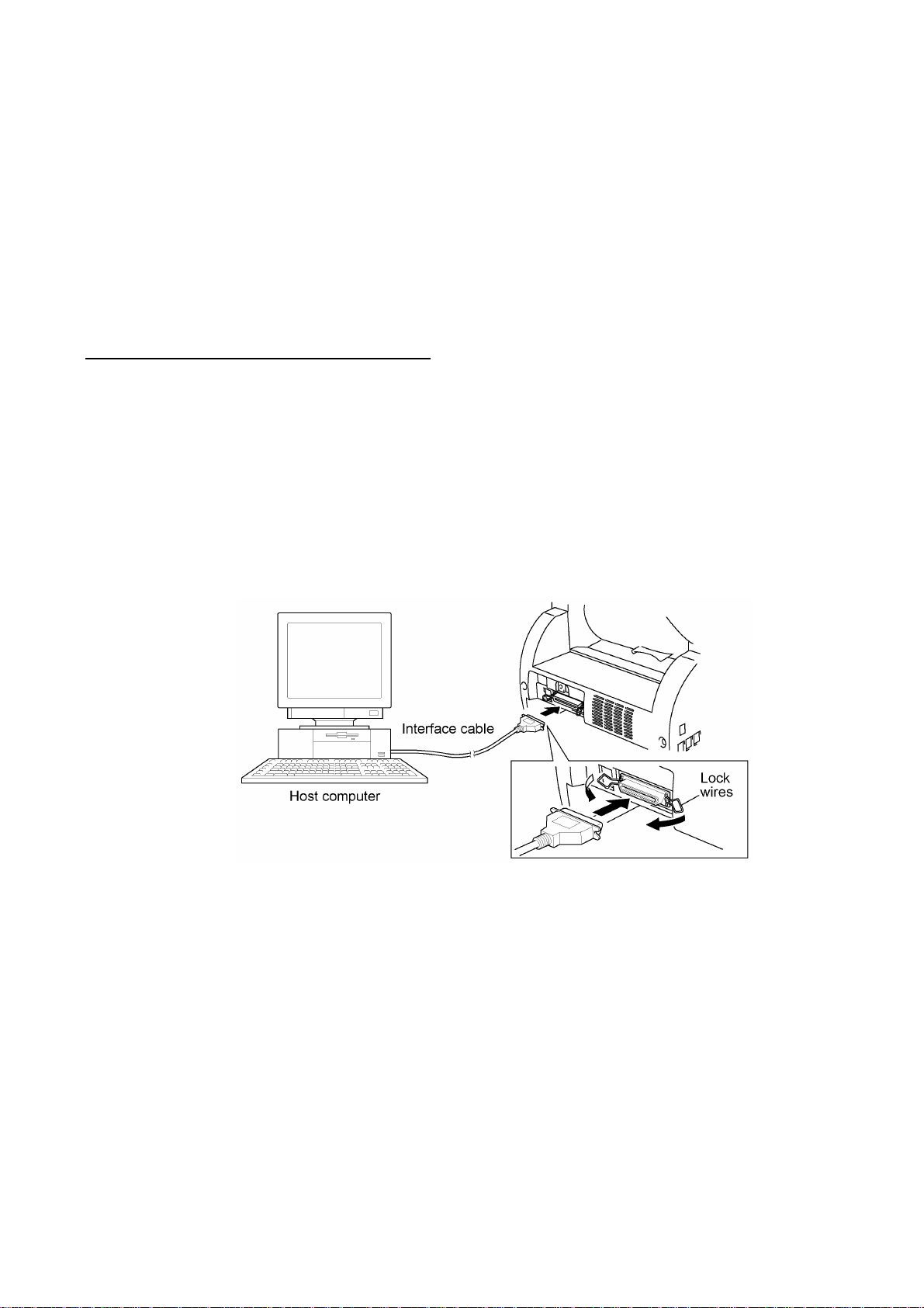
Connecting the machine to your computer
(1) Make sure that the machine's power cord is unplugged from a wall socket.
(2) Make sure that your computer is powered off.
(3) Connect the interface cable to the parallel interface port on the back of the machine and
secure it with the lock wires.
(4) Connect the other end of the interface cable to the printer port of your computer and secure
it with the two screws.
(5) Power on your computer.
(6) Plug the machine's power cord into a wall socket.
II - 1

Installing the update data onto the flash ROM of the machine
(1) Copy the update data and transfer utility onto the desired directory of the hard disk.
e.g., C:\UPDATE
(2) Click the Start button, point to Programs, and then click MS-DOS Prompt to open an MS-
DOS window.
(3) Type the drive letter where the update data and transfer utility are located. In the above
example, type C:\ from the command line and press the ENTER key.
Then type CD UPDATE and press the ENTER key.
(4) Check that your computer is connected with the machine correctly.
(5) To start the transfer utility transmitting the update data to the flash ROM of the machine,
type the following:
ICEN filename /b
Then press the ENTER key.
During downloading, the machine beeps intermittently.
Upon completion of the downloading, the machine beeps continuously.
NOTE: If the machine cannot return to the standby state after completion of downloading,
turn the power off and on.
II - 2

CHAPTER III.
THEORY OF OPERATION

CHAPTER III. THEORY OF OPERATION
CONTENTS
1. OVERVIEW...........................................................................................................III-1
2. MECHANISMS......................................................................................................III-2
2.1 Scanner Mechanism....................................................................................III-3
2.2 Laser Printing Mechanism...........................................................................III-5
2.2.1 Paper pick-up and registration mechanism............................................III-5
2.2.2 Print process mechanism......................................................................III-6
2.2.3 Heat-fixing mechanism..........................................................................III-8
2.2.4 Paper ejecting mechanism.....................................................................III-9
2.3 Sensors and Actuators.................................................................................III-10
3. CONTROL ELECTRONICS..................................................................................III-12

1. OVERVIEW
III - 1
* Provided on models supporting facsimile function.

2. MECHANISMS
The machine is classified into the following mechanisms:
n SCANNER MECHANISM - ADF mechanism
n LASER PRINTING MECHANISM - Paper pick-up and registration mechanism
n SENSORS AND ACTUATORS
- Document scanning mechanism
- Print process mechanism (consisting of charging,
exposing, developing, and transferring processes)
with paper feeding mechanism
- Heat-fixing mechanism with paper feeding
mechanism
- Paper ejecting mechanism
III - 2

2.1 Scanner Mechanism
This mechanism consists of the following:
- document tray ASSY which consists of a document chute and document tray,
- automatic document feeder (ADF) unit which consists of a document feed roller ASSY,
document ejection roller ASSY, ADF motor, and document front and rear sensors, and
- scanner unit which consists of a scanner top cover, CCD unit, CCD drive mechanism, CCD HP
sensor, and scanner base.
For details about the sensors, refer to Section 2.3.
III - 3

This scanner mechanism supports a dual scanning system.
(1) If you set documents with their faces up on the document chute and start the scanning
operation, the ADF motor rotates so that the document feed roller ASSY feeds those
documents into the ADF unit, starting from the top sheet to the bottom, page by page. Each
document curves downwards and turns to the right so as to advance above the CCD unit, and
then it is fed out to the document tray with the document ejection roller ASSY.
This way, documents move above the CCD unit being kept in a stationary position.
(2) If you open the scanner unit, put a sheet of document (or put a bound book opened) on the
glass of the scanner top cover, close the scanner unit, and start the scanning operation, then
the CCD drive mechanism will be driven. That is, the CCD motor rotates and its rotation will
be transmitted via the gear train to the CCD drive belt.
The CCD unit, which is supported and guided by the CCD rail, is secured to the CCD drive
belt. Clockwise and counterclockwise rotations of the CCD motor move the CCD unit to the
right and left, respectively.
In this scanning system, the CCD unit moves horizontally beneath a document being kept in
stationary position.
The CCD unit contains a charge coupled device (CCD) image sensor. The cold-cathode
fluorescent lamp illuminates a document and the reflected light of the scanned image data is
transmitted via the mirrors into the lens which reduces the scanned data so as to form the image
on the CCD.
III - 4

2.2 Laser Printing Mechanism
2.2.1 Paper pick-up and registration mechanism
III - 5

At the 1st stage, the controller drives the main motor without energizing the solenoid so that the
paper feed roller simply idles.
At the 2nd stage, the controller energizes the solenoid so that the paper feed roller no longer
rotates and the paper pick-up roller starts rotating to pick up paper into the machine, a sheet at a
time. After the leading edge of the pulled-in paper passes through the manual insertion sensor
actuator, the paper is further fed for the specified time length. Accordingly, the leading edge will
reach the paper feed roller where the paper skew will be eliminated.
At the 3rd stage, the controller deenergizes the solenoid to rotate the paper feed roller for feeding
paper to the transfer block in the drum unit.
When the leading and trailing edges of the paper pass through the registration sensor actuator, the
sensor signals them to the controller. According to those signals, the controller may determine the
first print position on the paper.
2.2.2 Print process mechanism
III - 6

The print process unit works with laser beam, electrical charges, and toner. The graph below
shows the transition of electrical charge on the surface of the laser-sensitive drum through the four
processes: charging, exposing, developing, and transferring processes.
III - 7

2.2.3 Heat-fixing mechanism
As the paper passes between the heater roller and the pressure roller in the heat-fixing unit, the
heater roller fuses the toner on the paper.
The controller monitors the internal resistance of the heater thermistor to keep the surface
temperature of the heater roller constant by turning the halogen heater lamp on and off.
III - 8

2.2.4 Paper ejecting mechanism
After the paper passes through the heat-fixing process, it will be ejected from the heat-fixing unit
by the paper ejection roller.
If the leading edge of the paper pushes up the actuator of the paper ejection sensor, the sensor
signals the start of paper ejection. If the trailing edge has passed through the sensor actuator, the
sensor signals the completion of paper ejection.
The paper will be turned over along the outer chute and ejected onto the main cover by the exit
roller.
III - 9

2.3 Sensors and Actuators
This machine has ten sensors: eight photosensors and two thermistors as described below.
Sensor name Type Located on
Document front sensor Photosensor Document sensor PCB
Document rear sensor Photosensor Document sensor PCB
Manual insertion sensor Photosensor Engine PCB
Registration sensor Photosensor Engine PCB
Cassette sensor Photosensor Engine PCB
Paper ejection sensor Photosensor Paper ejection sensor PCB
Toner sensor Photosensor Toner sensor (LED) PCB and toner
Cover sensor Photosensor Toner sensor (LED) PCB
Heater thermistor Thermistor Heat-fixing unit
In-casing temperature sensor Thermistor Left-hand plate of the main chassis
• Document front sensor which detects the presence of documents.
• Document rear sensor which detects the leading and trailing edges of pages to tell the control
circuitry when the leading edge of a new page has reached the starting position and when the
scan for that page is over.
• Manual insertion sensor which detects whether paper is inserted manually through the paper
slot or whether paper fed through the paper cassette has jammed.
• Registration sensor which detects the leading and trailing edges of recording paper, which
allows the controller to determine the registration timing and check paper jam.
• Cassette sensor which detects whether the paper cassette is loaded.
• Paper ejection sensor which detects whether the recording paper goes out of the machine.
• Toner sensor which detects whether there is toner or a toner cartridge is loaded.
• Cover sensor which detects whether the front cover is closed.
• Heater thermistor which allows the controller to monitor the temperature of the heater roller of
the fixing unit.
• In-casing temperature sensor which allows the controller to monitor the temperature inside the
machine.
sensor (light-receiver) PCB
The above photosensors are a photointerrupter consisting of a light-emitting
diode and a light-sensitive transistor. Each
of them has an actuator separately arranged
as shown on the next page.
III - 10
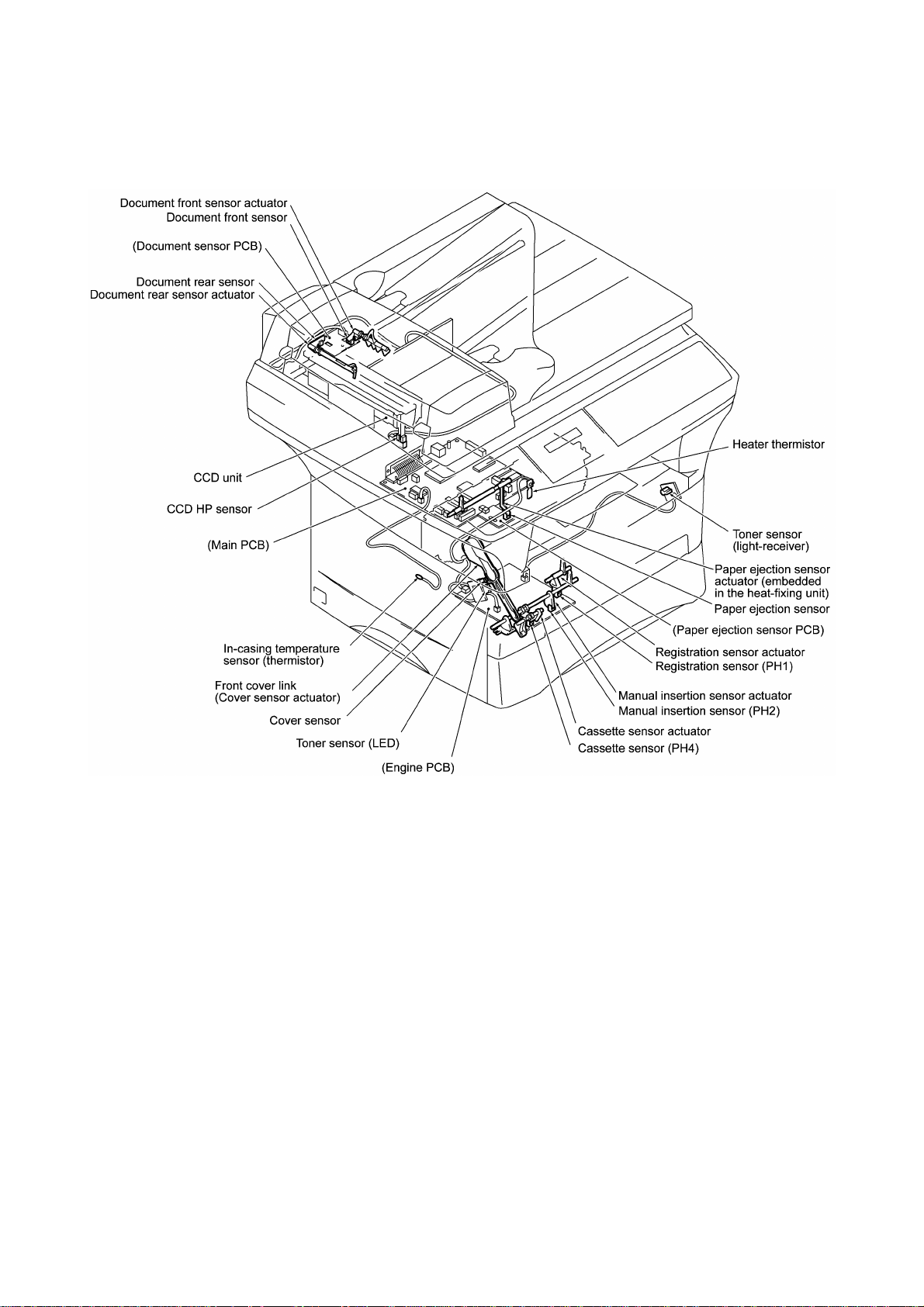
Location of Sensors and Actuators
III - 11
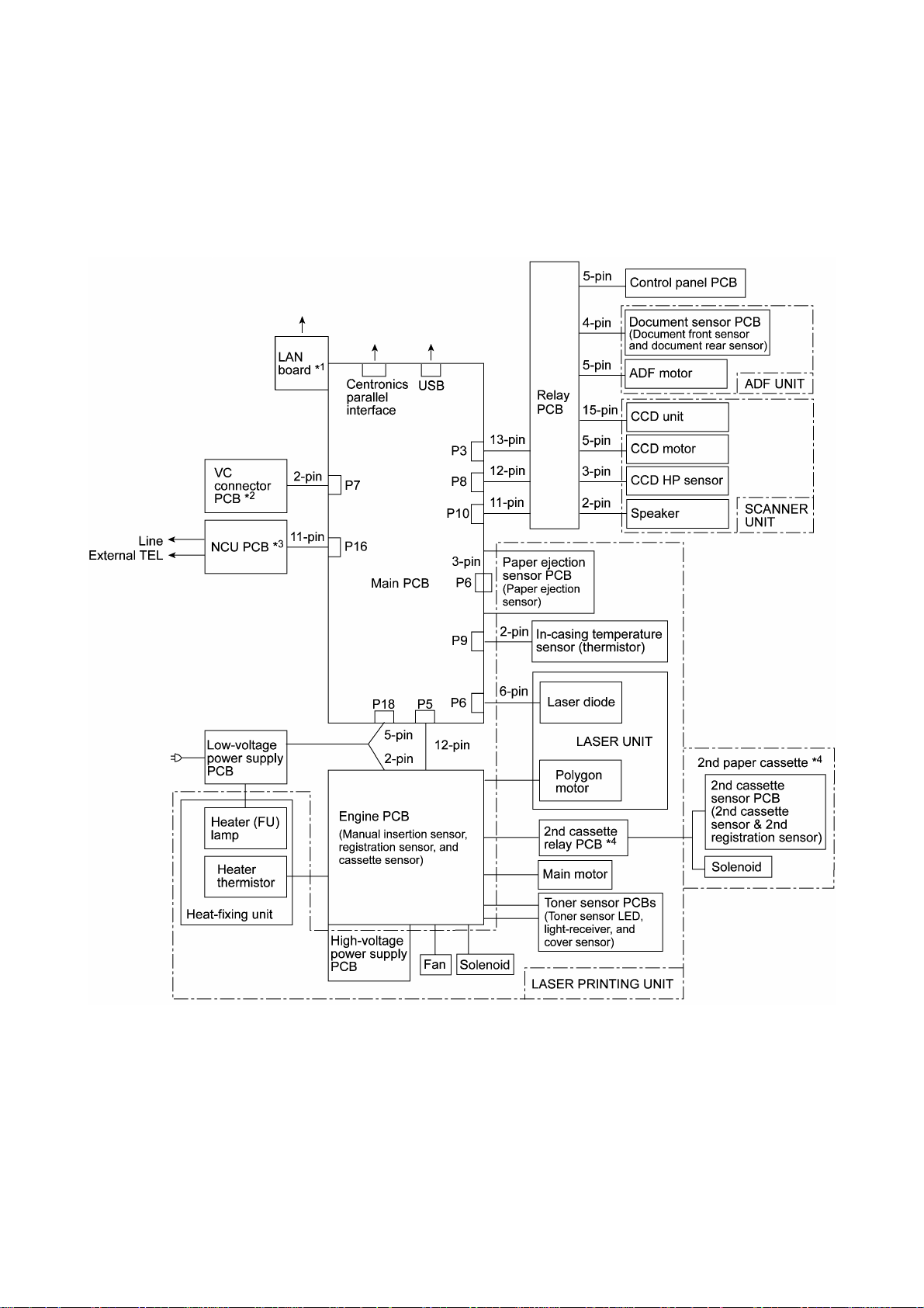
3. CONTROL ELECTRONICS
The hardware configuration of the machine is shown below.
*1Provided on models supporting LAN interface.
*2Provided on models supporting video capture.
*3Provided on models supporting facsimile function.
*4Provided on models available with a 2nd paper cassette (as an option).
Configuration of Machine
III - 12

CHAPTER IV.
DISASSEMBLY/REASSEMBLY AND
LUBRICATION

CHAPTER IV. DISASSEMBLY/REASSEMBLY AND
LUBRICATION
CONTENTS
1. DISASSEMBLY/REASSEMBLY...........................................................................IV-1
n Safety Precautions..............................................................................................IV-1
n Preparation.........................................................................................................IV-2
n How to Access the Object Component................................................................IV-2
n Disassembly Order Flow.....................................................................................IV-3
1.1 Lower Rear Cover..........................................................................................IV-4
1.2 Access Plates R and F...................................................................................IV-4
1.3 Paper Cassette...............................................................................................IV-5
1.4 Document Tray ASSY....................................................................................IV-6
1.5 Upper Rear Cover..........................................................................................IV-8
1.6 ADF Unit........................................................................................................IV-9
[ Disassembling the ADF Unit ].......................................................................IV-11
1.7 Scanner Unit and Control Panel ASSY...........................................................IV-16
[ Disassembling the Scanner Unit ].................................................................IV-19
[ Disassembling the Control Panel ASSY ]......................................................IV-24
1.8 Relay PCB.....................................................................................................IV-25
1.9 Speaker..........................................................................................................IV-26
1.10 Scanner Mount...............................................................................................IV-27
1.11 Paper Sub Tray and Tray Holder....................................................................IV-30
1.12 VC Cover, VC Bracket, and VC Connector PCB (for models supporting
video capture)................................................................................................IV-31
1.13 Front Cover
Front Sub Cover (for models not supporting video capture)............................IV-32
1.14 Outer Chute and Paper Pinch Rollers.............................................................IV-33
1.15 Main Cover.....................................................................................................IV-34
1.16 Switch Cover (for models not equipped with a power switch)..........................IV-35
1.17 Laser Unit.......................................................................................................IV-36
1.18 Heat-fixing Unit and FU Lamp........................................................................IV-37
1.19 Fan.................................................................................................................IV-41
1.20 Drive Gear ASSY and Main Motor ASSY........................................................IV-43
1.21 NCU Shield and NCU PCB*............................................................................IV-45
1.22 Bottom Plate, Main PCB, and Bottom Insulation Film.....................................IV-47
1.23 Low-voltage Power Supply PCB and Power Inlet............................................IV-51
i

1.24 Inner Insulation Film, High-voltage Power Supply PCB, Engine PCB,
and 2nd Cassette Relay PCB*........................................................................IV-53
1.25 Toner Sensor (light-receiver) PCB and Toner Sensor (LED) PCB...................IV-55
1.26 Gears and Paper Pick-up Roller.....................................................................IV-56
1.27 Paper Feed Roller ASSY................................................................................IV-57
1.28 Clutch Levers, Cassette Guide L, and Solenoid..............................................IV-58
1.29 Cleaning of High-voltage Contacts and Grounding Contacts...........................IV-59
2. LUBRICATION.....................................................................................................IV-61
[ 1 ] ADF unit.................................................................................................IV-61
[ 2 ] Scanner mount.......................................................................................IV-62
[ 3 ] Drive gear ASSY....................................................................................IV-63
[ 4 ] Paper cassette........................................................................................IV-64
ii

1. DISASSEMBLY/REASSEMBLY
nn Safety Precautions
To prevent the creation of secondary problems by mishandling, observe the following precautions
during maintenance work.
(1) Unplug the power cord from the power outlet before accessing parts or units inside the
machine. When having access to the power supply, be sure to unplug the power cord from
the power outlet.
(2) When servicing the optical system of the laser printing unit, be careful not to place
screwdrivers or other reflective objects in the path of the laser beam. Be sure to take off any
personal accessories such as wrist watches and rings before working on the printer. A
reflected beam, though invisible, can permanently damage your eyes.
(3) If the machine has been printing, allow the heat-fixing unit (inside this unit is a red-colored
heater roller) sufficient time to cool down before starting maintenance jobs. It is HOT!
(4) Be careful not to lose screws, washers, or other parts removed for parts replacement.
(5) Do not remove gears from the document feed roller ASSY or document ejection roller ASSY if
at all possible. Once removed, they will become unusable and new gears will have to be put
back in.
(6) When using soldering irons and other heat-generating tools, take care not to damage the resin
parts such as wires, PCBs, and covers.
(7) Before handling the PCBs, touch a metal portion of the machine to discharge static electricity;
otherwise, the electronic parts may be damaged due to the electricity charged in your body.
(8) When transporting PCBs, be sure to wrap them in conductive sheets such as aluminum foil.
(9) Be sure to reinsert self-tapping screws correctly, if removed. Unless otherwise specified,
tighten screws to the following torque values:
Taptite, bind B and cup B M3: 0.7 N•m
M4: 0.8 N•m
Taptite, cup S M3: 0.8 N•m
Other screws M3: 0.7 N•m
M4: 0.8 N•m
(10) When connecting or disconnecting cable connectors, hold the connector bodies not the
cables. If the connector has a lock, always slide the connector lock to unlock it.
(11) Before reassembly, apply the specified lubricant to the specified points. (Refer to Section 2 in
this chapter.)
(12) After repairs, check not only the repaired portion but also that the connectors and other
related portions function properly before operation checks.
IV - 1
nn Preparation
Prior to proceeding to the disassembly procedure,
(1) Unplug
- the power cord,
- the modular jack of the telephone line,
- the PC interface cable, and
- the modular jack of an external telephone set if connected. (Not shown below.)
(2) Remove
- the paper cassette and
- the drum unit (with toner cartridge loaded).
nn How to Access the Object Component
• On the next page is a disassembly order flow which helps you access the object components.
To remove the heat-fixing unit, for example, first find it on the flow and learn its number ( in
this case). You need to remove parts numbered , , , , , , , and so as to
access the heat-fixing unit.
• Unless otherwise specified, the disassembled parts or components should be reassembled in
the reverse order of removal.
IV - 2

nn Disassembly Order Flow
IV - 3

1.1 Lower Rear Cover
(1) Remove the three screws (two "a" and one "b") from the lower rear cover. Screw "b" is
provided on those models available with a 2nd paper cassette (as an option).
(2) Lightly pressing sections "X," pull out the lower rear cover.
"a" and "b": Screw, pan (washer) M4x10DB
1.2 Access Plates R and F
(1) Remove screw "c" that secures access plates R and F together to the main chassis.
(2) Remove screws "d" and "e" from access plate R.
(3) Take out access plates R and F together.
(4) Remove screw "f" to separate those access plates.
"c" to "f": Taptite, cup S M3x6
(Tightening torque: 0.5 N•m)
nn Reassembling Notes
• When reinstalling access plate F, fit the two tabs provided on the front end underneath the
center edge of the main chassis.
IV - 4

1.3 Paper Cassette
(1) Pull the pressure plate release lever to the front to release the pressure plate.
(2) Fully slide the side guide (R or L) inwards (in the direction of arrow •) and remove the screw.
Then release the latches (arrow ‚) and pull up the side guide (arrow ƒ).
(3) Release the pressure plate from the bosses (arrow „) and remove it (arrow …).
(4) Fully slide the paper rear guide to the front and lift it up (arrow †).
IV - 5

1.4 Document Tray ASSY
(1) Fully open the document tray ASSY.
(2) Lift up the document tray ASSY straight and pull the hinges up and out of the scanner unit.
(3) Remove the three screws from each of the hinges.
IV - 6

(4) Remove screw "a," then lightly tap the left end of the document chute to release the three
hooks from the document tray.
(5) Remove the sponge.
(6) Remove screw "b" to take off the support plate.
IV - 7

1.5 Upper Rear Cover
(1) Remove the two screws from the upper rear cover.
(2) Release section "a" from the latch provided on the scanner mount and pull the top of the
upper rear cover to the rear and upwards.
nn Reassembling Notes
• When installing the upper rear cover, first hook sections "b" onto the supports of the scanner
mount and push the upper rear cover into place.
IV - 8

1.6 ADF Unit
(1) Remove screw "a" from the harness support.
(2) Remove screw "b" to release the grounding wires.
(3) Disconnect the following from the relay PCB:
• CCD flat cable (P4)
• ADF motor harness (4-pin, P3)
• Document sensor harness (4-pin, P8)
IV - 9
"a": Taptite, cup B M3x8
"b": Taptite, cup S M3x6

(4) Turn the ADF unit in the direction of arrow •, remove the plastic retaining ring, and release
the arm (arrow ‚) from the boss provided on the scanner top cover. Turn the ADF unit back
into place.
(5) Open the ADF cover (arrow ƒ) and remove two screws "c."
(6) Lift up the ADF unit while pulling out the ADF motor harness, document sensor harness, and
grounding wire. The ADF supports also come off.
(7) Take off the harness support by removing screw "d."
IV - 10
"c" and "d": Taptite, cup B M3x8

[ Disassembling the ADF Unit ]
1) Open the ADF cover. Pull the ADF side cover outwards and release the ADF cover from the
bosses provided on the ADF side covers.
2) At each of the ADF side covers F and R, remove the screw, pull the unscrewed corner
outwards to release it from the document ejection chute, and unhook the latch.
3) Remove the document ejection chute (which has been secured with the screws removed in
step 2) above).
IV - 11

4) At the front end of the document feed roller shaft, remove the pawled bushing by pulling its
pawls outwards. At the rear end, pull the bushing outwards and lift up the document feed
roller ASSY.
5) At the front end of the upper LF roller (gray) shaft, remove the pawled bushing by pulling its
pawls outwards. At the rear end, pull the bushing outwards and lift up the upper LF roller
ASSY.
6) Remove the two screws and take off the ADF motor.
If you do not need to remove the ADF parts, skip to step 10).
7) Peel off the ADF film.
NOTE: Once removed, the ADF film will become unusable and a new part will have to be put
back in.
8) Remove the screw and take off the spring plate A, separation rubber, rubber holder, and
compression spring.
9) Push the hooks provided on the upper ADF chute and remove the pressure rollers and their
springs.
IV - 12
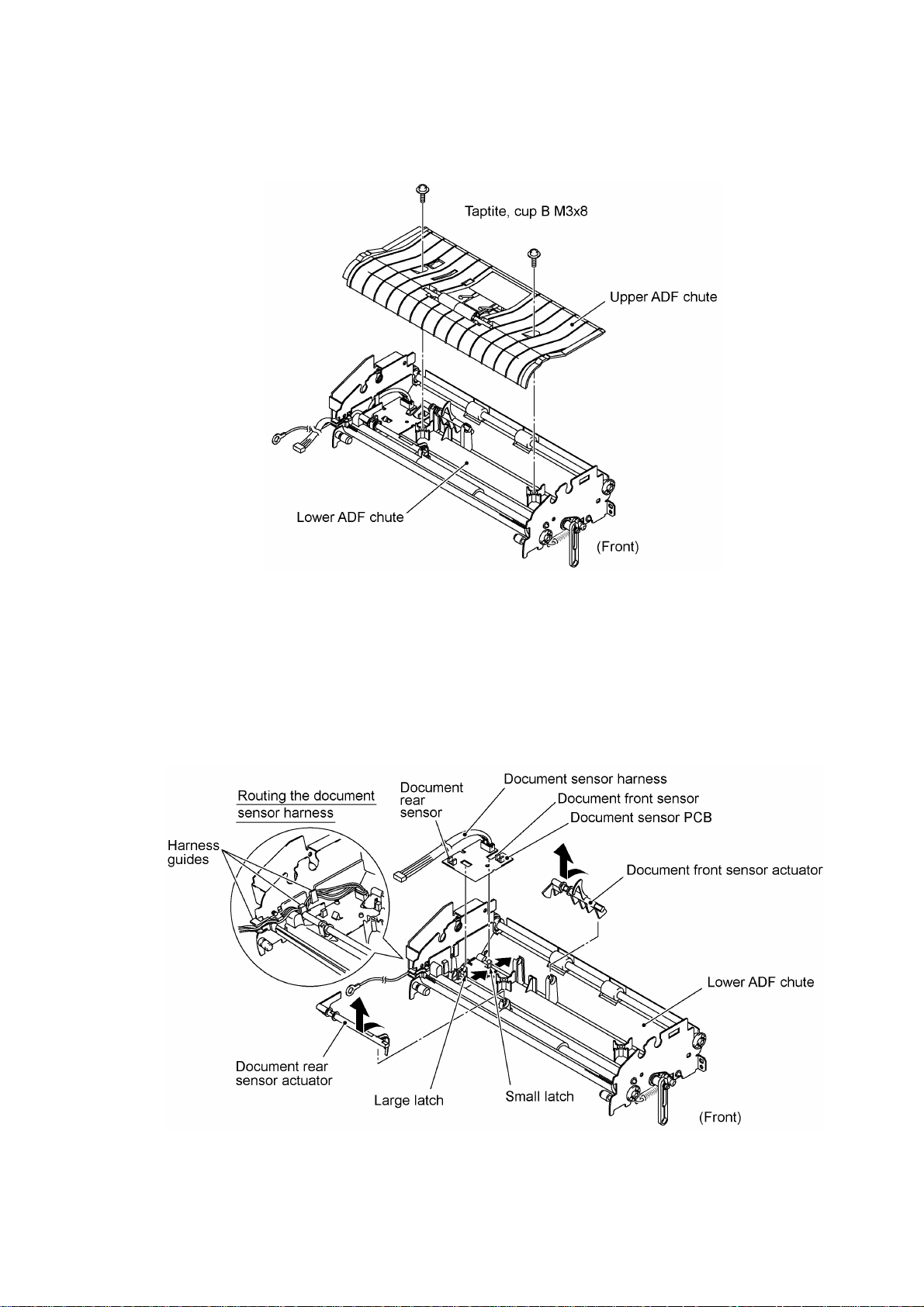
10) Remove the two screws and lift up the upper ADF chute.
11) Turn the document front sensor actuator as shown below and lift it up.
12) Turn the document rear sensor actuator as shown below and lift it up.
13) Disconnect the document sensor harness from the document sensor PCB and take out its
harness from the harness guides.
14) Unhook the two latches (large and small latches in this order) from the document sensor PCB
and lift it up.
IV - 13

15) At the front end of the document ejection roller shaft, remove the pawled bushing by pulling its
pawls outwards. At the rear end, pull the bushing outwards and lift up the document ejection
roller ASSY.
16) Remove the three screws and take off the motor bracket.
17) At the front end of the lower LF roller (black) shaft, remove the pawled bushing by pulling its
pawls outwards. At the rear end, pull the bushing outwards and remove the lower LF roller
ASSY.
18) Turn the lower ADF chute upside down.
19) Pull the arm outwards and take it off.
20) At the rear side of the lower ADF chute, remove the gear 19/36 by pulling its pawl outwards.
21) Remove the gear 64 by pulling its pawl outwards.
22) Unhook the two springs.
23) Pull out the white roller bushing F by pulling its pawls outwards.
24) Remove the white roller together with the white roller bushing R and gear 27.
IV - 14

nn Reassembling Notes
• Take care not to mistake the upper LF roller ASSY (gray) for the lower LF roller ASSY (black).
• When setting the document sensor PCB back into place, do not push it down straight, but first
fit the PCB in the large latch and then fit it in the small latch (see the illustration given on page
IV-13).
• Be sure to route the document sensor harness through the three harness guides so that it will
not interfere with the document rear sensor actuator. (See the illustration given on page IV-13.)
• Reinstall the ADF motor with its connector side facing up. (See the illustration given on page
IV-12.)
• Reinstall the ADF side covers so that the tabs of the ADF side plates become fitted inside the
ribs provided on the ADF side covers. (See the illustration given on page IV-11.)
• When reinstalling the ADF side cover R, be sure to route the document sensor harness, ADF
motor harness, and grounding wire between the boss and the ADF side cover R. (See the
illustration given on page IV-11.)
• When reinstalling the ADF unit, first set the ADF support onto rear pin "x" of the ADF unit, set
the ADF unit back into place, set the other ADF support onto front pin "y," then secure those
ADF supports with two screws "c." (See the illustration given on page IV-10.)
• When connecting the ADF motor harness, document sensor harness, and grounding wires to
the relay PCB, route them as shown below.
IV - 15

1.7 Scanner Unit and Control Panel ASSY
(1) Disconnect the following from the relay PCB:
- CCD motor harness
- Panel harness
- Scanner HP sensor harness
IV - 16

(2) Slide the scanner unit (with the control panel ASSY) to the rear by approx. 5 mm and then lift
it up. (For the disassembly procedure of the scanner unit, refer to page IV-19.)
IV - 17

(3) Remove the three screws from the underside of the scanner base.
(4) Insert the tip of a flat screwdriver into each of the four holes provided in the scanner base and
unhook the four latches while lifting up the control panel ASSY.
(5) Disconnect the panel harness from the control panel PCB. (For the disassembly procedure of
the control panel ASSY, refer to page IV-24.)
nn Reassembling Notes
• When reinstalling the scanner unit, fit the holes and cutouts provided in the scanner unit over
screws "A" and pawls of the scanner mount, respectively, and then slide the scanner unit to the
front. (Refer to page IV-17.)
• When connecting the CCD motor harness, panel harness, and scanner HP sensor harness to
the relay PCB, route them as shown below.
IV - 18

• When connecting the CCD motor harness, panel harness, and scanner HP sensor harness to
the relay PCB, route them as shown below.
[ Disassembling the Scanner Unit ]
The disassembling job of the scanner unit should be done in a clean room to prevent dust or dirt
from getting into the scanner unit.
1) Remove the four screws from the scanner top cover.
2) Separate the scanner top cover from the scanner base.
IV - 19

3) Turn the gear 17/97 to move the CCD unit to the right to make the following job easier.
4) Remove screw "a" and take out the CCD rail clamp. (See the illustration given on the next
page.)
5) Remove two screws "b" from the CCD idle pulley holder, then remove the CCD drive belt
from the idle pulley.
6) Lift up the CCD rail together with the CCD unit and CCD drive belt, and then disconnect the
CCD flat cable.
NOTE: When handling the CCD unit, do not touch the CCD PCB or glasses but hold the
hatched sections as shown below.
7) Pull out the CCD rail from the CCD unit.
8) Remove the CCD lock.
IV - 20
"a": Taptite, cup B M3x8
"b": Taptite, pan B M3x10

9) Pull up the CCD motor harness and disconnect it from the CCD motor.
10) Remove three screws "c" from the motor bracket.
11) Lift up the motor bracket.
12) Remove two screws "d" from the CCD motor. The scanner grounding wire also comes off.
13) Disconnect the CCD HP sensor harness from the sensor.
14) Remove the CCD HP sensor.
IV - 21

15) Remove the four screws and take off the flat cable clamp. Remove sponge 3 attached with
adhesive tape.
16) Remove the CCD flat cable (which is attached with adhesive tape).
17) Remove the four screws and take off the guide plate.
18) Remove tape and sponges 1, then take out the panel harness and CCD HP sensor harness.
NOTE: Once removed, the sponges 1 will become unusable and new ones will have to be put
back in.
IV - 22

nn Reassembling Notes
• Route the panel harness and CCD HP sensor harness through the three notches, then tape
them as illustrated on the previous page.
• When replacing the CCD flat cable with a new one, be sure to arrange the new cable as
illustrated below, then route it along the positioning rib as shown on the previous page.
• Set the CCD motor back into place with its connector side facing up as shown on page IV-21.
When securing the motor with screws "d," be sure to secure the scanner grounding wire also as
shown on page IV-21.
• Route the CCD motor harness and scanner grounding wire as illustrated below.
• Set the CCD lock in the release (forward) position. If the CCD lock is placed in the lock
position, the CCD home positioning will fail in the next powering-up sequence. If this happens,
turn the CCD lock to the release position.
IV - 23

[ Disassembling the Control Panel ASSY ]
1) Turn the control panel ASSY upside down.
2) Remove two screws "a."
3) Slightly lift up the control panel PCB, then unlock the FPC key connector and disconnect the
FPC key. Next, unlock the LCD cable connector and disconnect the LCD flat cable.
4) Remove six screws "b."
5) Remove the key support plate and FPC key.
"a": Taptite, cup B M2.6x8
"b": Taptite, cup B M3x6
6) As shown below, slightly pull the clamp outwards and take out the LCD while pulling the LCD
flat cable gently.
NOTE: Do not take out the LCD except when the LCD is defective and requires replacement.
nn Reassembling Notes
• Before reinstalling the LCD to the control panel, wipe fingerprints or dust off the LCD surface
and control panel window with a soft cloth.
• A new LCD is covered with a protection sheet. Before installing it, remove the protection sheet.
IV - 24

1.8 Relay PCB
(1) Disconnect the following harnesses from the relay PCB:
- Speaker harness
- Main-relay (panel) harness
- Main-relay (CCD) harness
- Main-relay (motors) harness
(2) Remove the two screws.
(3) Take out the relay PCB.
nn Reassembling Notes
• When setting the relay PCB back into place, be careful with the installation direction. The
printed letters should not be upside down.
IV - 25

1.9 Speaker
(1) Press the pawl in the direction of arrow À and slide the speaker spring in the direction of
(2) Lift up the speaker.
arrow Á.
IV - 26

1.10 Scanner Mount
(1) Remove two screws "a."
(2) Open the front cover and remove two screws "b."
(3) Pull the tabs of the scanner mount to the front and upwards (in the direction of arrows À) to
release them from the bosses provided on the main cover.
(4) Lift up the scanner mount in the direction of arrow Á.
"a": Stepped screw
(Tightening torque: 0.78 N•m)
"b": Taptite, cup S M3x10
(Tightening torque: 0.78 N•m)
IV - 27

(5) Turn the scanner mount upside down.
(6) Peel off anti-static brushes.
NOTE: Once removed, they will become unusable and new parts will have to be put back in.
(7) As shown below, warp the gear-equipped end of the exit roller and remove it.
IV - 28

nn Reassembling Notes
• When setting the scanner mount back into place:
- at the right-hand side, raise the main-relay (panel) harness coming through the main cover up
and through cutout "x" provided in the scanner mount.
- at the left-hand side, pull up the main-relay (motors) harness and chassis grounding wire and
raise them up and through square cutout "y" provided in the scanner mount. Also pull up the
main-relay (CCD) harness and raise it up and through round cutout "z."
IV - 29

1.11 Paper Sub Tray and Tray Holder
(1) Pull out the paper sub tray.
(2) While pushing down the center of the paper sub tray to warp it (in the direction of arrow À),
pull it out of the tray holder (arrow Á).
(3) Insert the tip of a small flat screwdriver into the tray holder (in the direction of arrow À) and
pull up the tray holder (arrow Á).
IV - 30

1.12 VC Cover, VC Bracket, and VC Connector PCB (for models supporting video capture)
(1) Remove two screws ("a" and "b"), then take off the VC cover.
(2) Remove screw "c," take out the VC bracket together with the VC connector PCB, and
disconnect the VC harness.
(3) Remove two screws "d," then take off the VC connector PCB.
nn Reassembling Notes
• The routing of the VC harness is shown on page IV-34.
"a": Taptite, cup S M3x10
"b": Taptite, bind S M3x8
"c" and "d": Taptite, cup S M3x6
IV - 31
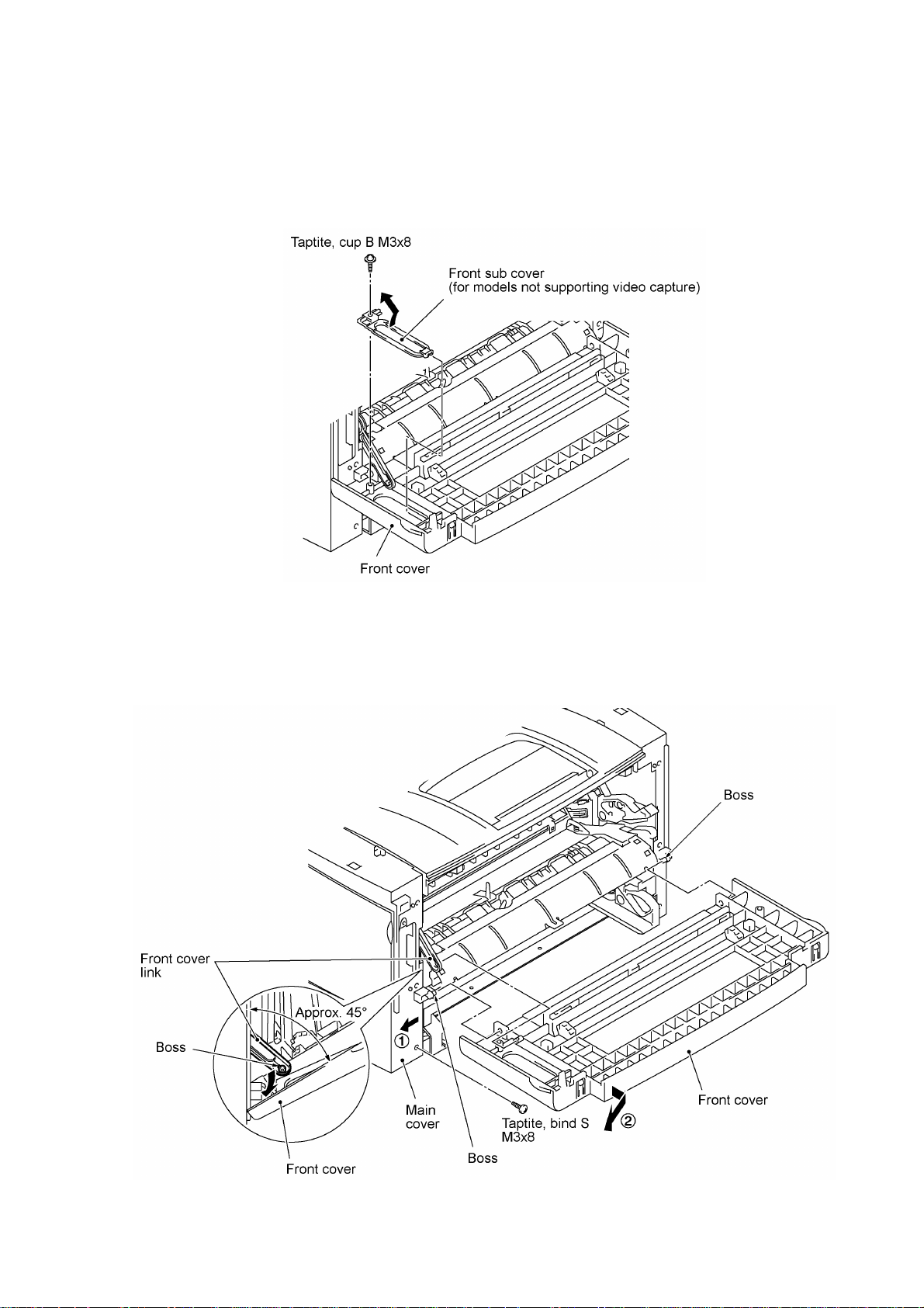
1.13 Front Cover
Front Sub Cover (for models not supporting video capture)
(1) For models not supporting video capture:
Remove the screw and take off the front sub cover from the front cover.
(2) Remove the screw from the left bottom of the front side of the main cover.
(3) Hold the front cover at an angle of 45° and pull the front cover link to the left to release it from
the front cover.
(4) Pull the bottom left front corner of the main cover to the left (in the direction of arrow •) and
release the front cover from the boss provided on the main cover (arrow ‚).
IV - 32

1.14 Outer Chute and Paper Pinch Rollers
(1) Pull up the outer chute and open it (in the direction of arrow •).
(2) Remove the chute springs from the hooks provided on the main cover (arrow ‚), then lift up
the outer chute (arrow ƒ).
(3) Remove the paper pinch rollers, their supports, and their springs.
IV - 33

1.15 Main Cover
(1) Remove two screws "a" from the front side of the main cover.
(2) Remove two screws "b" from the rear side of the main cover, and then pull corner edges "X"
outwards to dislocate the main cover from the main chassis. Make sure that the cutout
provided in the main cover is dislocated from the power inlet.
(3) Unhook the two latches with the tip of a flat screwdriver, then lift up the main cover.
nn Reassembling Notes
• When reinstalling the main cover, route the main-relay (panel) harness, main-relay (CCD)
harness, and main-relay (motors) harness through the respective cutouts provided in the main
cover, as illustrated above.
"a" and "b": Taptite, bind S M3x8
IV - 34

1.16 Switch Cover (for models not equipped with a power switch)
(1) Push the locks of the switch cover as shown below and remove it.
IV - 35
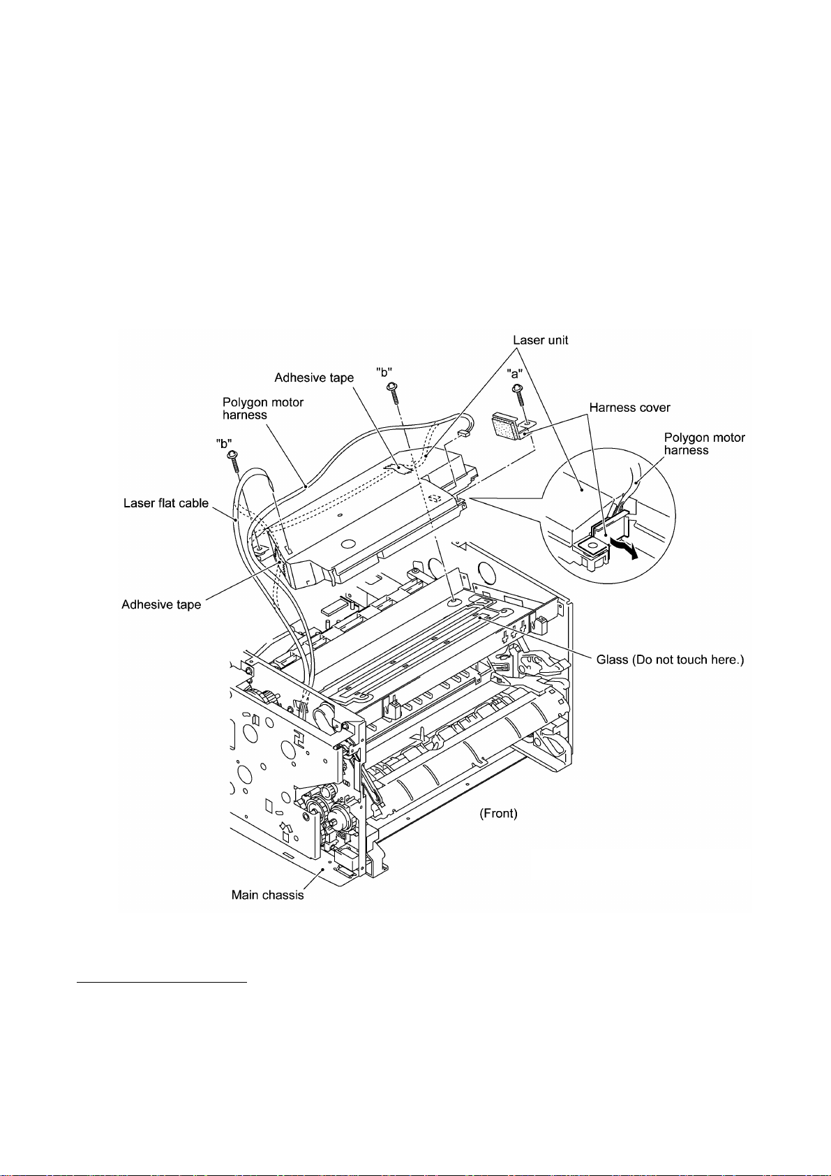
1.17 Laser Unit
(1) Remove screw "a" and take off the harness cover.
(2) Remove two screws "b."
(3) Disconnect the polygon motor harness and laser flat cable from the laser unit.
(4) Lift up the laser unit.
NOTE: When handling the laser unit, take care not to touch the inside of the unit, glass, or
mirror.
NOTE: On the small PCB in the laser unit is a 2-pin connector which is for the adjustment in
the factory. Do not disturb it.
nn Reassembling Notes
• Before putting the laser unit back into place, check for any toner particles, paper dust or dirt,
and clean them out.
• After routing the polygon motor harness and laser flat cable, tape them onto the laser unit as
shown above.
"a" and "b": Taptite, cup S M3x16
IV - 36

1.18 Heat-fixing Unit and FU Lamp
(1) Remove the screw from the harness duct. The chassis grounding wire also comes off.
(2) Peel off tape and take off the main-relay (motors) harness, main-relay (CCD) harness, and VC
harness* from the harness duct.
(3) Unhook the harness duct from the main chassis in the directions of arrows • and ‚.
*Provided on models supporting video capture
IV - 37

(4) Remove three screws (two "a" and one "b").
(5) Disconnect the long heater wire (of the heater harness) from the upper center of the heat-
fixing unit.
(6) Disconnect the short heater wire (of the heater harness) from the left end of the heat-fixing
unit.
(7) Lift up the heat-fixing unit and disconnect the heater thermistor harness from the engine PCB.
IV - 38
"a": Stepped screw
"b": Taptite, cup S M3x8

(8) To take out the FU lamp from the heat-fixing unit, remove two screws "c."
(9) Unhook the two latches outwards (in the direction of arrows •) with the tip of a flat
screwdriver and open the upper cover (arrow ‚). The upper and lower covers will become
separated from each other.
(10) Loosen screw "d" (arrow ƒ).
(11) Remove screw "e," slightly lift up the heater roller gear (arrow „), hold the lock plate L of the
FU lamp between your fingers, and pull out the FU lamp from the heater roller (arrow …).
CAUTION: Do not touch the FU lamp. If you have touched it, clean it thoroughly with
alcohol.
nn Reassembling Notes
• When setting the FU lamp into the heat-fixing unit, be sure to insert the right end of the wire
into the lock plate R as illustrated above.
"c": Taptite, cup B M3x20
"d": Pan cup M3x6
"e": Taptite, pan M3x10DB
IV - 39

• When securing the lock plate R with screw "d," be sure to use the plastic jig as shown below to
avoid damaging the edge of the FU lamp with a screwdriver.
Lock plate R
FU lamp
"d"
Plastic jig
• A new heat-fixing unit will be provided with the heater thermistor harness being taped to the
unit. Before installing the unit, remove the tape.
• When setting the heat-fixing unit back into place, make sure that the heater wires are routed
through the latch of the fan duct (see the illustration given on page IV-41) and then route the
long heater wire as shown below.
• If you remove and reinstall the heat-fixing unit because of any failure, make the machine enter
the maintenance mode (see Note) after completion of reassembly and then make it exit from
the mode (by pressing the 9 key twice). Otherwise, the heat-fixing unit may not become
energized because of the following reason:
If the failure of the heat-fixing unit is caused by an opening of the thermistor circuit (that senses
the temperature of the heat-fixing unit), the system misinterprets the hot heater as being cold.
As a result, the temperature of the heat-fixing unit may become excessively high. To prevent
the system from heating the hot heater further at the next powering-on, it is designed so that
the heater will not be energized. To cancel this setting, you need to carry out the above
maintenance-mode procedure.
(Note) Entry into the maintenance mode
Machines w/ fax: Press the Function/Menu, *, 2, 8, 6, and 4 keys.
Machines w/o fax: Press the Menu, 0, 2, 8, 6, and 4 keys.
IV - 40

1.19 Fan
(1) Disconnect the fan harness from the engine PCB.
(2) Remove two screws, take out the heater wires from the latch of the fan duct, and take off the
fan duct together with the fan.
IV - 41

(3) As shown below, pull the fan duct outwards and take out the fan.
nn Reassembling Notes
• Put the fan back into place so that the rating label faces outwards and upside down.
• Route the heater wires through the latch of the fan duct as shown on the previous page.
IV - 42

1.20 Drive Gear ASSY and Main Motor ASSY
(1) Remove five screws from the drive gear ASSY.
(2) Tilt the drive gear ASSY towards you while taking care not to drop the develop joint and
spring, and then disconnect the main motor harness.
(3) Remove the front cover link and idle gear 56 from the main chassis.
IV - 43
*Provided on models supporting video capture

(4) Remove four screws and take off the main motor ASSY from the drive gear ASSY.
nn Reassembling Notes
• If you have removed the gear 39/98 from the drive gear ASSY, hook the spring and tape it as
shown below.
IV - 44

1.21 NCU Shield and NCU PCB*
(1) Remove three screws from the NCU shield, then take off the NCU shield.
(*Provided on models supporting facsimile function.)
(2) USA version: Disconnect the main-NCU harness from the main PCB.
European version: Disconnect the main-NCU harness and main-NCU harness 2 from the main
PCB. See the illustration given on the next page.
(3) Remove the screw from the NCU PCB and take out the PCB.
IV - 45

nn Reassembling Notes
[USA version]
• Route the main-NCU harness above the main-relay (motors) harness as illustrated below.
[European version]
• As illustrated below, route the main-NCU harness and main-NCU harness 2 between the NCU
PCB and the power supply bracket to prevent them from interfering with the primary circuitry on
the NCU PCB. Then install the NCU shield.
IV - 46

1.22 Bottom Plate, Main PCB, and Bottom Insulation Film
(1) Disconnect the following harnesses and flat cable from the main PCB:
• Main-relay (panel) harness (13-pin, P3)
• Main-LV-engine harness (5-pin, P18)
• Laser flat cable (P6)
• Engine-main harness (12-pin, P5)
• VC harness*1 (2-pin, P7)
• Main-relay (CCD) harness (12-pin, P8)
• In-casing temperature sensor harness (2-pin, P9)
• Main-relay (motors) harness (11-pin, P10)
*1 Provided on models supporting video capture
*2 Provided on the European version
IV - 47

(2) Turn the main chassis upside down.
(3) Remove 14 screws (nine "a" and five "b").
(4) Slightly lift up the bottom plate and pull it to the rear until you can remove screw "c."
(5) Remove screw "c" to release the grounding wire.
(6) For models available with a 2nd paper cassette: Removes screw "d" that secures the 2nd
cassette relay PCB bracket to the bottom plate.
(7) Pull the bottom plate to the rear and out of the main chassis.
"a" and "d": Taptite, cup S M3x6
"b" Taptite, bind B M4x12
"c": Screw, pan (washer) M3.5x6
IV - 48

(8) Remove screw "d" and disconnect the paper ejection sensor PCB from the main PCB.
(9) Remove five screws (three "e" and two "f"), then take off the main PCB from the bottom plate.
(10) Remove the bottom insulation film.
nn Reassembling Notes
• When putting the bottom plate back into place, make sure that the grounding wire is looped and
routed through the support film (as illustrated on page IV-51) and then secure the grounding
wire to the bottom plate with screw "c" (shown on the previous page).
• After you replace the main PCB, be sure to follow the flowchart given on the next page.
"d" and "e": Taptite, cup S M3x6
"f": Machine screw, pan M3x6
IV - 49

Setting up the main PCB after replacement
IV - 50

1.23 Low-voltage Power Supply PCB and Power Inlet
(1) Remove two screws "g" and take off the rear underbar.
(2) Remove screw "h."
(3) Slightly lift up the low-voltage power supply PCB and disconnect the heater harness and
main-LV-engine harness. The low-voltage power supply PCB is connected to the power inlet
with soldered lead wires.
(4) Remove screw "i."
(5) While holding up the low-voltage power supply PCB, take out the power inlet from the main
chassis to the inside in the direction of the arrow shown below.
(6) To separate the power inlet from the low-voltage power supply PCB, unsolder the two lead
wires from the PCB.
IV - 51
"g" and "i": Taptite, cup S M3x6
"h": Taptite, cup S M3x6
(Tightening torque: 0.5 N•m)

nn Reassembling Notes
• When connecting the power inlet to the low-voltage power supply PCB, insert the brown and
blue lead wires into eyelets L and N in the PCB, respectively, and then solder those wires on
the solder side of the PCB.
• After setting the power inlet back into place, fold the grounding wire into two and route the fold
through cutout "Y" provided in the support film as shown on the previous page.
• When reinstalling the low-voltage power supply PCB, route the main-LV-engine harness
through cutout "X" provided in the support film as shown on the previous page.
IV - 52

1.24 Inner Insulation Film, High-voltage Power Supply PCB, Engine PCB, and 2nd Cassette Relay
PCB*
(*Provided on models available with a 2nd paper cassette)
(1) Remove screw "a" and take off the inner insulation film.
(2) Remove three screws (two "b" and one "c") from the high-voltage power supply PCB and
engine PCB.
(3) Slightly lift up the high-voltage power supply PCB and disconnect it from the engine PCB.
(4) Pull the spring up and out.
(5) Slightly hold up the engine PCB and disconnect the following harnesses:
• Toner sensor (light-receiver) harness (3-pin, P1)
• Main-LV-engine harness (2-pin, P15)
• 2nd cassette relay harness* (8-pin, P8)
• Heater thermistor harness (2-pin, P6), if the heat-fixing unit has not been removed
• Fan harness (2-pin, P7), if the fan has not been removed
• Toner sensor (LED) harness (4-pin, P10)
• Main motor harness (6-pin, P9)
• Polygon motor harness (5-pin, P12)
• Solenoid harness (2-pin, P13)
"a," "b," and "c": Taptite, bind B M4x12
IV - 53

(6) For models available with a 2nd paper cassette: Pull the 2nd cassette relay PCB bracket to
take out its harness. Remove the screw and take off the 2nd cassette relay PCB from its
bracket.
nn Reassembling Notes
• Before reinstalling the high-voltage power supply PCB, push in the spring with a flat
screwdriver until it snaps into place as shown below.
• Before reinstalling the high-voltage power supply PCB, check the high-voltage contacts for any
toner particles, paper dust or dirt, and clean them out.
IV - 54
 Loading...