

Page 1

FACSIMILE EQUIPMENT
SERVICE MANUAL
MODEL: FAX3550/3650/8000P/8200P
MFC4450/4550/4550plus
MFC6550MC/7550MC/7650MC
MFC9000/9500
Page 2

© Copyright Brother 1998
All rights reserved.
No part of this publication may be reproduced in any
form or by any means without permission in writing
from the publisher.
Specifications are subject to change without notice.
Page 3

PREFACE
This publication is a Service Manual covering the specifications, construction, theory of operation, and maintenance of the Brother facsimile equipment. It includes information required for
field troubleshooting and repair—disassembly, reassembly, and adjustment—so that service
personnel will be able to understand equipment function, to rapidly repair the equipment and
order any necessary spare parts.
To perform appropriate maintenance so that the facsimile equipment is always in best condition
for the customer, the service personnel must adequately understand and apply this manual.
This manual is made up of six chapters and appendices.
CHAPTER I. GENERAL DESCRIPTION
CHAPTER II. INSTALLATION
CHAPTER III. THEORY OF OPERATION
CHAPTER IV. DISASSEMBL Y/REASSEMBLY AND LUBRICATION
CHAPTER V. MAINTENANCE MODE
CHAPTER VI. ERROR INDICATION AND TROUBLESHOOTING
APPENDICES Circuit Diagrams
This manual describes the model and its versions to be destined for major countries. The specifications
and functions are subject to change depending upon each destination.
Page 4

SAFETY INFORMATION
Laser Safety (110 - 120V Model only)
This printer is certified as a Class 1 laser product under the US Department of Health and Human
Services (DHHS) Radiation Performance Standard according to the Radiation Control for Health
and Safety Act of 1968. This means that the printer does not produce hazardous laser radiation.
Since radiation emitted inside the printer is completely confined within the protective housings and
external covers, the laser beam cannot escape from the machine during any phase of user operation.
CDRH Regulations (110 - 120V Model only)
The Center for Device and Radiological Health (CDRH) of the US Food and Drug Administration
implemented regulations for laser products on August 2, 1976. These regulations apply to laser
products manufactured from August 1, 1976. Compliance is mandatory for products marketed in the
United States. The label shown below indicates compliance with the CDRH regulations and must be
attached to laser products marketed in the United States.
The label for Japanese products
MANUFACTURED: AUGUST 1998 K
BROTHER INDUSTRIES, LTD.
15-1 Naeshiro-cho Mizuho-ku Nagoya 467-8561, Japan.
This product complies with FDA radiation
performance standards, 21 CFR Subchapter J.
Page 5

CHAPTER I.
GENERAL DESCRIPTION
Page 6

CONTENTS
1. EQUIPMENT OUTLINE................................................................................. I-1
1.1External Appearance and Weight........................................................... I-1
1.2Components............................................................................................I-1
2. SPECIFICATIONS..........................................................................................I-2
Page 7

1. EQUIPMENT OUTLINE
1.1 External Appearance and Weight
The figure below shows the equipment appearance and approximate dimensions.
251 (H)
Weight: Machine proper Approx. 8.5 kg (excluding the drum unit and toner cartridge)
In package Approx. 13.5 kg (FAX3550/3650/8000P/8200P)
1.2 Components
The equipment consists of the following major components:
Multi-purpose
sheet feeder
Drum unit with toner
cartridge loaded
Laser unit
383 (W)
(excluding the handset)
Approx. 14 kg (MFC4450/4550/4550plus/6550MC/7550MC/
452 (D)
(Unit: mm)
7650MC/9000/9500)
Top cover
Control panel ASSY
Heat-fixing unit
Inner cover
Handset
Gear drive unit
Low-voltage power
supply ASSY
Bottom plate
Main cover
Scanner frame ASSY
NCU PCB ASSY
Main PCB
Relay PCB
High-voltage power
supply ASSY
I – 1
Page 8

2. SPECIFICATIONS
MODEL FAX3550 MFC4550 MFC6550MC MFC7550MC
COLOR 1267 1138 1138 1138
PRINTER Option
Engine — HL-720 HL-730 HL-730
PPM — 6 6 6
dpi — 600 x 600 600 x 600 600 x 600
Paper Capacity 200 200 200 200
Standards — Windows GDI (600x600) Windows GDI (600x600) Windows GDI (600x600)
Emulation — No PCL4 (300x300) PCL4 (300x300)
Memory (Typical) — 512 KB 512 KB 1 MB
Memory (Min.) — 300 KB 400 KB 1 MB
Fonts Resident — No 24-bit map (PCL4 Comp) 24-bit map (PCL4 Comp)
Fonts Disk Based — No Yes Yes
Paper Handling LTR, LGL, A4 LTR, LGL, EXE, A4, B5, A5 LTR, LGL, EXE, A4, B5, A5 LTR, LGL, EXE, A4, B5, A5
Multi-purpose Sheet Custom Size (2.85x5-8x14) Custom Size (2.85x5-8x14) Custom Size (2.85x5-8x14) Custom Size (2.85x5-8x14)
Feeder
Printer Driver — Windows 3.1, 95 Driver with Windows 3.1, 95 Driver with Windows 3.1, 95 Driver with
Toner Life (5%/page) 2200 pages 2200 pages 2200 pages 2200 pages
Utility Software — — RPC RPC
SCANNER Option
Color/Mono — Mono Mono Mono
Gray Scale — 64 256 256
dpi — 400 x 400 600 x 600 600 x 600
Twain — Yes Yes Yes
ADF Capacity (pages) (30) 30 30 30
Formats — TIFF/BMP (by M/L) TIFF/BMP (by M/L) TIFF/BMP (by M/L)
OCR — Option Yes Yes
Envelope (BL/C5/COM 10/Mona) Envelope (BL/C5/COM 10/Mona) Envelope (BL/C5/COM 10/Mona) Envelope (BL/C5/COM 10/Mona)
Auto Installer Program Auto Installer Program Auto Installer Program
(1/2)
COPY
dpi 200 x 400 200 x 400 600 class 600 class
No. of Copies 1-99 1-99 1-99 1-99
Sorting No No Yes Yes
Reduction/Enlargement 50-200% 50-200% 50-200% 50-200%
FAX
Modem ROCKWELL V12 ROCKWELL V12 ROCKWELL V24 ROCKWELL V24
Modem Speed 14400 bps (FAX only) 14400 bps (FAX only) 14400 bps (FAX only) 14400 bps (FAX only)
CCITT Group G3 G3 G3 G3
Coding Method MH/MR/MMR MH/MR/MMR MH/MR/MMR MH/MR/MMR
Transmission Speed 6 sec. 6 sec. 6 sec. 6 sec.
Input/Output Width 8.5"/8.5" 8.5"/8.5" 8.5"/8.5" 8.5"/8.5"
LCD Size 16 x 1 16 x 2 16 x 2 16 x 2
Super Fine Yes (Send only) Yes (Send only) Yes (Send only) Yes
Gray Scale 64 64 64 64
Smoothing Yes Yes Yes Yes
Handset Yes Yes Yes Yes
One-touch Dial 20 x 2 12 x 2 12 x 2 12 x 2
Speed Dial 100 36 36 100
Telephone Index Yes Yes Yes Yes
Contrast Super L/Auto/Super D Super L/Auto/Super D Super L/Auto/Super D Super L/Auto/Super D
Multi-resolution Transmission
FAX/TEL Switch Yes Yes Yes Yes
Distinctive Ringing Yes Yes Yes Yes
Caller ID Yes Yes Yes Yes
Next FAX-reservation Yes Yes Yes Yes
Help Yes Yes Yes Yes
TAD Interface Yes Yes Yes Yes
Yes Yes Yes Yes
I – 2
Page 9

MODEL FAX3650 MFC4450 MFC4550plus MFC7650MC
COLOR 1267 1138 1138 1138
PRINTER Option
Engine — HL-720 HL-720 HL-730
PPM — 6 6 6
dpi 200 x 200 600 x 600 600 x 600 600 x 600
Paper Capacity 200 200 200 200
Standards Windows GDI (200x200) Windows GDI (600x600) Windows GDI (600x600) Windows GDI (600x600)
Emulation — No PCL4 (300x300) PCL4 (300x300)
Memory (Typical) — 512 KB 512 KB 1 MB
Memory (Min.) — 300 KB 400 KB 600 KB
Fonts Resident — No 24-bit map (PCL4 Comp) 24-bit map (PCL4 Comp)
Fonts Disk Based — No Yes Yes
Paper Handling LTR, LGL, A4 LTR, LGL, A4, B5, A5 LTR, LGL, A4, B5, A5 LTR, LGL, A4, B5, A5
Multi-purpose Sheet — Custom Size (2.85x5-8x14) Custom Size (2.85x5-8x14) Custom Size (2.85x5-8x14)
Feeder
Printer Driver — Windows 3.1, 95 Driver with Windows 3.1, 95 Driver with Windows 3.1, 95 Driver with
Toner Life (5%/page) 2200 pages 2200 pages 2200 pages 2200 pages
Utility Software — — RPC RPC
SCANNER Option
Color/Mono — Mono Mono Mono
Gray Scale — 64 64 256
dpi — 400 x 400 400 x 400 600 x 600
Twain — Yes Yes Yes
ADF Capacity (pages) — 30 30 30
Formats (Import) —
Formats (Export) — TIFF/BMP/UNI TIFF/BMP/MAX TIFF/BMP/MAX
OCR — Option Yes Yes
Envelope (BL/C5/COM 10/Mona) Envelope (BL/C5/COM 10/Mona) Envelope (BL/C5/COM 10/Mona)
Auto Installer Program Auto Installer Program Auto Installer Program
TIFF/BMP/PCX/DCX/BTF/BTX/UNI TIFF/BMP/PCX/DCX/BTF/BTX/MAX TIFF/BMP/PCX/DCX/BTF/BTX/MAX
(1/2)
COPY
dpi 200 x 400 200 x 400 200 x 400 600 class
No. of Copies 1-99 1-99 1-99 1-99
Sorting Yes No No Yes
Reduction/Enlargement 50-200% 50-200% 50-200% 50-200%
FAX
Modem ROCKWELL V12 Toshiba ROCKWELL V12 ROCKWELL V24
Modem Speed 14400 bps (FAX only) 9600 bps (FAX only) 14400 bps (FAX only) 14400 bps (FAX only)
CCITT Group G3 G3 G3 G3
Coding Method MH/MR/MMR MH/MR/MMR MH/MR/MMR MH/MR/MMR
Transmission Speed 6 sec. 9 sec. 6 sec. 6 sec.
Input/Output Width 8.5"/8.5" 8.5"/8.5" 8.5"/8.5" 8.5"/8.5"
LCD Size 16 x 1 16 x 2 16 x 2 16 x 2
Super Fine Yes Yes Yes Yes
Gray Scale 64 64 64 64
Smoothing Yes Yes Yes Yes
Handset Yes No Yes Yes
One-touch Dial 20 x 2 12 x 2 12 x 2 12 x 2
Speed Dial 100 36 36 100
Telephone Index Yes Yes Yes Yes
Contrast Super L/Auto/Super D Super L/Auto/Super D Super L/Auto/Super D Super L/Auto/Super D
Multi-resolution Transmission
FAX/TEL Switch Yes Yes (with External) Yes Yes
Distinctive Ringing Yes Yes (with External) Yes Yes
Caller ID Yes No Yes Yes
Next FAX-reservation Yes Yes Yes Yes
Help Yes Yes Yes Yes
TAD Interface Yes Yes Yes Yes
Yes Yes Yes Yes
I – 3
Page 10

MODEL FAX8000P MFC9000 MFC9500 FAX8200P
COLOR 1138 1138 1138 1138
PRINTER Option Option
Engine — HL-730 HL-730 —
PPM — 6 6 —
dpi —
Paper Capacity 200 200 200 200
Standards — Windows GDI Windows GDI —
Emulation — PCL4 PCL4 —
Memory (Typical) — 512 KB 512 KB —
Memory (Min.) — 400 KB 400 KB —
Fonts Resident — 24-bit map (PCL4 Comp) 24-bit map (PCL4 Comp) —
Fonts Disk Based — Yes Yes —
Paper Handling A4, B5, A5 A4, B5, A5 A4, B5, A5 A4
Multi-purpose Tray
Printer Driver — Windows 3.1, 95 Driver with Windows 3.1, 95 Driver with
Toner Life (5%/page) 2200 pages 2200 pages 2200 pages 2200 pages
Utility Software —
SCANNER Option Option
Color/Mono — Mono Mono —
Gray Scale — 256 256 —
dpi — 600 x 600 600 x 600 —
Twain — Yes Yes —
ADF Capacity (pages) 30 30 30 —
Formats — TIFF/BMP TIFF/BMP —
OCR — Option Yes —
Custom Size (73x127-126x350 mm) Custom Size (73x127-216x350 mm) Custom Size (73x127-216x350 mm)
Envelope (DL/C5/COM 10/Mona) Envelope (DL/C5/COM 10/Mona) Envelope (DL/C5/COM 10/Mona)
600 x 600 (GDI) / 300 x 300 (PCL4) 600 x 600 (GDI) / 300 x 300 (PCL4)
Auto Installer Program Auto Installer Program
Mac Driver (Option) Mac Driver (Option)
Remote Priter Console (RPC) Remote Printer Console (RPC)
—
—
—
—
(1/2)
COPY
dpi 200 x 400 300 x 400 300 x 400 200 x 400
No. of Copies 1-99 1-99 1-99 1-99
Sorting
Reduction/Enlargement 50-200% 50-200% 50-200% 50-200%
FAX
Modem ROCKWELL V12 ROCKWELL V12 ROCKWELL V24 ROCKWELL V12
Modem Speed 14400 bps (FAX only) 14400 bps (FAX only) 14400 bps (FAX only) 14400 bps (FAX only)
CCITT Group G3 G3 G3 G3
Coding Method MH/MR/MMR MH/MR/MMR MH/MR/MMR MH/MR/MMR
Transmission Speed 6 sec. 6 sec. 6 sec. 6 sec.
Input/Output Width 8.5"/8.5" 8.5"/8.5" 8.5"/8.5" 8.5"/8.5"
LCD Size 16 x 1 16 x 2 (STN) 16 x 2 (STN) 16 x 1
Super Fine (Send) Yes Yes Yes Yes
Super Fine (Receive)
Gray Scale 64 64 64 64
Smoothing Yes Yes Yes Yes
Handset No No No No
One-touch Dial 20 x 2 12 x 2 12 x 2 20 x 2
Speed Dial 100 100 100 100
Telephone Index Yes Yes Yes Yes
Contrast Light/Auto/Dark Light/Auto/Dark Light/Auto/Dark Light/Auto/Dark
Multi-resolution Transmission
FAX/TEL Switch Yes Yes Yes Yes
Distinctive Ringing Yes Yes Yes —
Caller ID
Next FAX-reservation Yes Yes Yes Yes
Help Yes Yes Yes Yes
TAD Interface Yes Yes Yes Yes
Available with optional memory
Available with optional memory Available with optional memory Available with optional memory
Yes Yes Yes Yes
Yes (U.K., Sweden, Holland and France) Yes (U.K., Sweden, Holland and France) Yes (U.K., Sweden, Holland and France) Yes (U.K., Sweden, Holland and France)
Yes Yes Yes
Yes
I – 4
Page 11

MODEL FAX3550 MFC4550 MFC6550MC MFC7550MC
FAX
Coverpage Yes, Super Yes, Super Yes, Super Yes, Super
Polling Type Std/Del/Seq Std/Del/Seq Std/Del/Seq Std/Del/Seq
Receive password Yes Yes Yes Yes
Delayed Transmission Yes, 3 timings Yes, 3 timings Yes, 3 timings Yes, 3 timings
Call Reservation Yes Yes Yes Yes
Callback Message Yes Yes Yes Yes
Page Memory (TX)* 300 KB (30 pgs: MMR) 200 KB (20 pgs: MMR) 300 KB (30 pgs: MMR) 700 KB (70 pgs: MMR)
Out-of-paper Reception* 400 KB (40 pgs: MMR) 400 KB (40 pgs: MMR) 600 KB (60 pgs: MMR) 1.5 MB (150 pgs: MMR)
Super Quick Scan Yes Yes Yes Yes
Auto Reduction Yes Yes Yes Yes
ECM Yes Yes Yes Yes
Broadcasting Y e s Yes Yes Yes
Multi Transmission Yes Yes Y es Yes
MESSAGE CENTER
TAD Feature No No Yes (Hardware & PC) Yes (Hardware & PC)
ICM Recording Time No No Hardware: 15 min. Hardware: 30 min.
Paging No No Yes (Hardware & PC) Yes (Hardware & PC)
Toll Saver No No Yes (Hardware & PC) Yes (Hardware & PC)
OGM No No Yes (Hardware & PC) Yes (Hardware & PC)
Mail Box No No Yes (PC only) Yes (PC only)
Fax-on-demand No No Yes (PC only) Yes (PC only)
Voice-on-demand No No Yes (PC only) Yes (PC only)
FAX Forwarding Yes Yes Yes Yes
FAX Retrieval Yes Yes Yes Yes
(2/2)
MACHINE MEMORY 0.75 MB 0.75 MB 1 MB 2 MB
OPTIONAL MEMORY 1 or 2 MB 1 or 2 MB 1 or 2 MB 1 or 2 MB
(FAX & PRINTER FLEX)
PC FAX (Send/Receive) Option Yes (by M/L) Yes (by M/L) Yes (by M/L)
Standard — Class 1, 2 Class 1, 2 Class 1, 2
DATA MODEM No No No No
INTERFACE
Printer Interface —
PC Interface
Extended I/O Interface — —
Simultaneous
Sends FAX and Prints — Yes Yes Yes
Receives FAX and Prints
Receives FAX and Scans
Prints and Scans — Yes Yes Yes
Receives FAX and Copies
Prints and Copies — Yes Yes Yes
RS-232C
(8-pin modular connector)
MULTI-FUNCTION LINK
— Yes Yes Yes
— Yes Yes Yes
— Yes Yes Yes
Centronics parallel (w/o cable) Centronics parallel (w/o cable) Centronics parallel (w/o cable)
MULTI-FUNCTION LINK PRO MULTI-FUNCTION LINK PRO MULTI-FUNCTION LINK PRO
———
RS-232C and RS-422 RS-232C and RS-422
(supported by an optional serial (supported by an optional serial
interface board RS-100M) interface board RS-100M)
* CCITT#1 Chart in the Standard Mode, MMR
I – 5
Page 12

MODEL FAX3650 MFC4450 MFC4550plus MFC7650MC
FAX
Coverpage Yes, Super Yes, Super Yes, Super Yes, Super
Polling Type Std/Del/Seq Std/Del/Seq Std/Del/Seq Std/Del/Seq
Delayed Transmission Yes, 13 timings Yes, 3 timings Yes, 3 timings Yes, 13 timings
Call Reservation Yes Yes (with External) Yes Yes
Callback Message Yes Yes Yes Yes
Page Memory (TX)* 1 MB (100 pgs: MMR) 300 KB (30 pgs: MMR) 300 KB (30 pgs: MMR) 800 KB (80 pgs: MMR)
Out-of-paper Reception* 1.1 MB (110 pgs: MMR) 600 KB (60 pgs: MMR) 600 KB (60 pgs: MMR) 1.0 MB (100 pgs: MMR)
Super Quick Scan Yes Yes Yes Yes
ECM Yes Yes Yes Yes
Broadcasting Yes Yes Yes Yes
Multi Transmission No Yes Yes No
MESSAGE CENTER
ICM Recording Time No No No Hardware: 30 min.
Paging Yes (Hardware & PC) Yes (Hardware & PC) Yes (Hardware & PC) Yes (Hardware & PC)
Toll Saver No No No Yes (Hardware & PC)
OGM No No No Yes (Hardware & PC)
Mail Box No No Yes (PC only) Yes (PC only)
Fax-on-demand No No No Yes (PC only)
Voice-on-demand No No No Yes (PC only)
FAX Forwarding Yes Yes Yes Yes
FAX Retrieval Yes Yes Yes Yes
(2/2)
MACHINE MEMORY 2 MB 1 MB 1 MB 2 MB
OPTIONAL MEMORY 1 or 2 MB No 1 or 2 MB 1 or 2 MB
(FAX & PRINTER FLEX)
PC FAX (Send/Receive) Option Yes (by M/L) Yes (by M/L) Yes (by M/L)
Standard — SMSI SMSI SMSI
DATA MODEM No No No No
INTERFACE
Printer Interface —
PC Interface
Extended I/O Interface — — —
Simultaneous
Sends FAX and Prints — Yes Yes Yes
Receives FAX and Prints
Receives FAX and Scans
Prints and Scans — Yes Yes Yes
Receives FAX and Copies
Prints and Copies — Yes Yes Yes
RS-232C
(8-pin modular connector)
MULTI-FUNCTION LINK
— Yes Yes Yes
— Yes Yes Yes
— Yes Yes Yes
Centronics parallel (w/o cable) Centronics parallel (w/o cable) Centronics parallel (w/o cable)
MULTI-FUNCTION LINK PRO MULTI-FUNCTION LINK PRO MULTI-FUNCTION LINK PRO
———
RS-232C and RS-422
(supported by an optional serial
interface board RS-100M)
* CCITT#1 Chart in the Standard Mode, MMR
I – 6
Page 13

MODEL FAX8000P MFC9000 MFC9500 FAX8200P
FAX
Coverpage Yes, Super Yes, Super Yes, Super Yes, Super
Polling Type Std/Del/Seq/Sec Std/Del/Seq/Sec Std/Del/Seq/Sec Std/Del/Seq/Sec
Receive password Yes/Plus Yes/Plus Yes/Plus Yes/Plus
Delayed Transmission Yes, 3 timings Yes, 3 timings Yes, 3 timings Yes, 3 timings
Call Reservation Yes Yes Yes Yes
Callback Message Yes Yes Yes Yes
Page Memory (TX)* 300 KB (30 pgs: MMR) 300 KB (30 pgs: MMR) 300 KB (30 pgs: MMR) 1 MB (100 pgs: MMR)
Out-of-paper Reception* 400 KB (40 pgs: MMR) 600 KB (40 pgs: MMR) 600 KB (60 pgs: MMR) 1.1 MB (110 pgs: MMR)
Super Quick Scan Yes Yes Yes Yes
Auto Reduction Yes Yes Yes Yes
ECM Yes Yes Yes Yes
Broadcasting Up to 140 destinations Up to 124 destinations Up to 124 destinations Up to 190 destinations
Multi Transmission Yes Yes Y es Yes
MESSAGE CENTER
TAD Feature No No Yes (Hardware & PC) No
ICM Recording Time No No Hardware: 15 min. No
Paging No No Yes (Hardware & PC) No
Toll Saver No No Yes (Hardware & PC) No
OGM UK/SWISS/AUS/GER UK/SWISS Yes (Hardware & PC) UK/SWISS/GER
Mail Box No No Yes (PC only) No
Fax-on-demand No No Yes (PC only) No
Voice-on-demand No No Yes (PC only) No
FAX Forwarding Yes Yes Yes Yes
FAX Retrieval Yes Yes Yes Yes
(2/2)
MACHINE MEMORY 0.75 MB 1 MB 1 MB 2 MB
OPTIONAL MEMORY 1 or 2 MB 1 or 2 MB 1 or 2 MB 1 or 2 MB
(FAX & PRINTER FLEX)
PC FAX (Send/Receive) Option Yes Yes Option
Standard — Class 2 Class 2 —
DATA MODEM No No No No
INTERFACE
Printer Interface —
PC Interface
CONNECT 5000 INTERFACE CONNECT 5000 INTERFACE
Extended I/O Interface —
Simultaneous
Sends FAX and Prints — Yes Yes —
Receives FAX and Prints
Receives FAX and Scans
Prints and Scans — Yes Yes —
Receives FAX and Copies
Prints and Copies — Yes Yes —
RS-232C
(8-pin modular connector) (8-pin modular connector)
—YesYes—
—YesYes—
—YesYes—
Centronics parallel (w/o cable) Centronics parallel (w/o cable) —
MULTI-FUNCTION LINK PRO MULTI-FUNCTION LINK PRO
——
RS-232C and RS-422 RS-232C and RS-422
(supported by an optional serial (supported by an optional serial
interface board RS-100M) interface board RS-100M)
RS-232C
—
* CCITT#1 Chart in the Standard Mode, MMR
I – 7
Page 14

CHAPTER II.
INSTALLATION
Page 15

CONTENTS
1. INSTALLING THE UPDATE DATA TO THE FACSIMILE EQUIPMENT...............II-1
Page 16
1. INSTALLING THE UPDATE DATA TO THE
FACSIMILE EQUIPMENT
If the program version is updated or the main PCB is replaced, install the update program onto the
flash ROM of the main PCB.
The program installation requires a host computer satisfying the following requirements:
- CPU Pentium 75 or higher
- RAM 8MB or greater (16MB recommended for Windows 95)
- OS Windows 3.1/3.11 or Windows 95
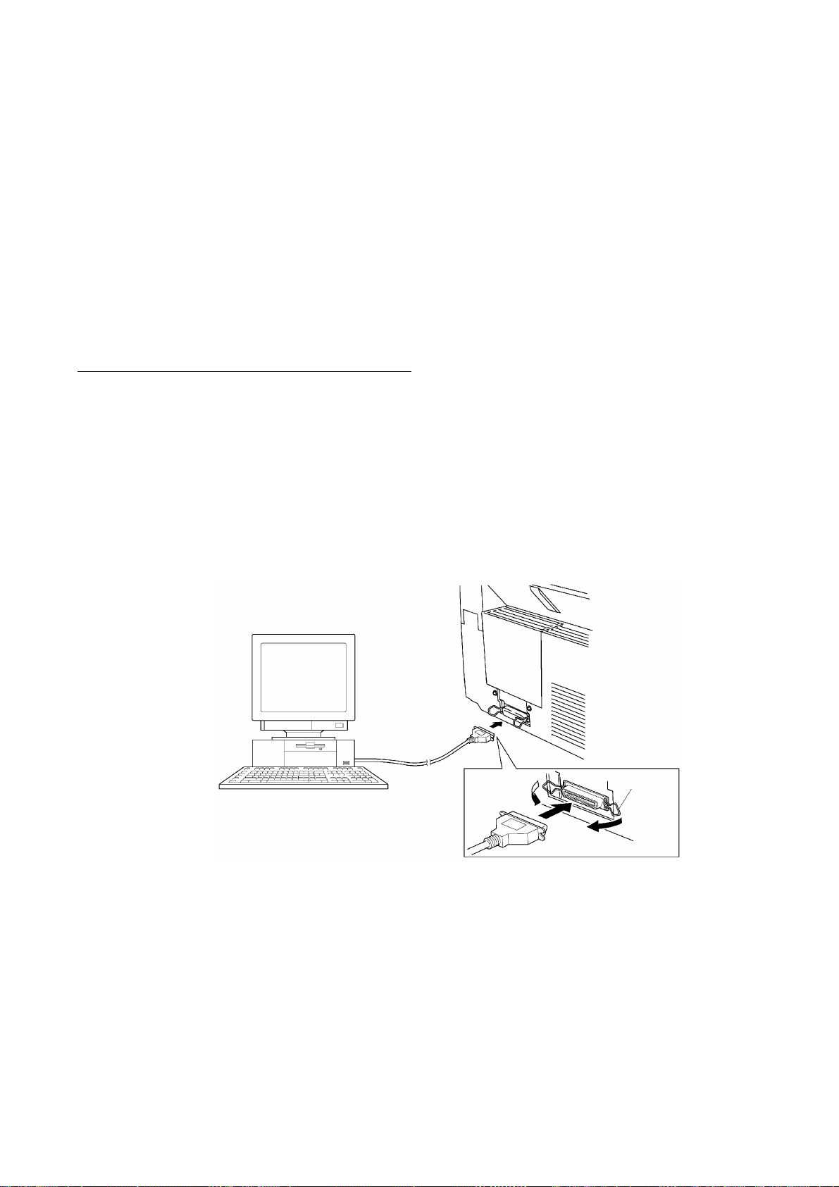
Connecting the equipment to your computer
(1) Make sure that the equipment's power cord is unplugged from a wall socket.
(2) Make sure that your computer is powered off.
(3) Connect the interface cable to the parallel interface port on the back of the equipment and
secure it with the lock wires.
(4) Connect the other end of the interface cable to the printer port of your computer and secure
it with the two screws.
(5) Power on your computer.
(6) Plug the equipment's power cord into a wall socket.
Host computer
Interface cable
Lock
wires
II - 1
Page 17

Installing the update data onto the flash ROM of the facsimile equipment
(1) Load the floppy disk which stores the update data and transfer utility into the floppy disk
drive of your computer.
(Or, copy the update data and transfer utility onto the same directory of the hard disk.)
(2) Click the Start button, point to Programs, and then click MS-DOS Prompt to open an MS-
DOS window.
(3) Type the drive letter where the update data and transfer utility are located. If it is a floppy
disk drive, type A:\ from the command line and press the ENTER key.
(4) Check that your computer is connected with the facsimile equipment correctly.
(5) To start the transfer utility transmitting the update data to the flash ROM of the facsimile
equipment, type the following:
A:\ICEN filename /b
Then press the ENTER key.
The equipment beeps and shows the "CONNECTING" on the LCD for one second.
Then, the equipment shows the "DOWNLOADING" on the LCD and starts receiving data
downloaded from the host computer.
During downloading, the equipment beeps intermittently.
Upon completion of the downloading, the equipment beeps continuously.
II - 2
Page 18

CHAPTER III.
THEORY OF OPERATION
Page 19

CONTENTS
1. OVERVIEW.....................................................................................................III-1
2. MECHANISMS................................................................................................III-2
2.1Scanner Mechanism.............................................................................. III-3
2.1.1Document feeding and ejecting mechanism................................... III-3
2.1.2Document scanning mechanism..................................................... III-3
2.2Laser Printing Mechanism...................................................................... III-4
2.2.1Paper pulling-in, registration, feeding, and ejecting mechanism..... III-4
2.2.2Print process mechanism................................................................ III-6
(1) Charging process.................................................................... III-7
(2) Exposing process.................................................................... III-7
(3) Developing process................................................................. III-8
(4) Transferring process................................................................ III-8
(5) Erasing process....................................................................... III-8
2.2.3Heat-fixing mechanism................................................................... III-9
2.3Sensors and Actuators........................................................................... III-10
3. CONTROL ELECTRONICS........................................................................... III-12
3.1Configuration...........................................................................................III-12
3.2Main PCB................................................................................................III-13
3.3Relay PCB..............................................................................................III-23
3.4NCU PCB................................................................................................III-24
3.5Control Panel PCB................................................................................. III-27
3.6Power Supply PCBs............................................................................... III-28
[ 1 ]Low-voltage power supply PCB.................................................. III-28
[ 2 ]High-voltage power supply PCB................................................. III-29
Page 20
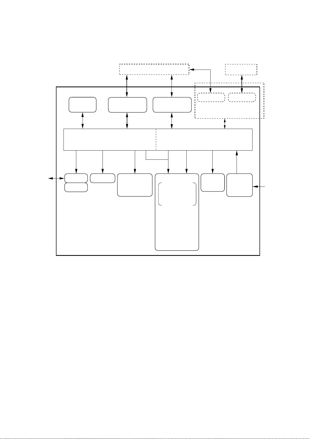
1. OVERVIEW
Line
Control
panel
NCU
Handset
PC/AT
RS-232C RS-422
RS-232C
(Modular connector)
[FAX3550/3650/
8000P/8200P]
Centronics
parallel interface
[MFC4450/
4550/4550plus/
6550MC/7550MC/7650MC/
9000/9500]
Optional serial interface
(Extended I/O connector)
[MFC6550MC/7550MC/
7650MC/9000/9500]
Fax Control Section Laser Printing Control Section
Printer
data
Laser printing unit
Charging, exposing,
developing,
transferring, erasing,
and heat-fixing
processes
- Electrical charger
- Laser unit
(including the polygon
motor)
- Laser-sensitive drum
- Developer roller
- Transfer roller
- Eraser lamp
- Heater roller
- Main motor
Paper
feeding
mechanism
Low- and
high-voltage
power
supplies
Speaker
Scanner unit
- LED array
- CCD unit
- Scanner motor
Fax data
MAC
AC
III – 1
Page 21

2. MECHANISMS
The equipment is classified into the following mechanisms:
■ SCANNER MECHANISM – Document feeding and ejecting mechanism
■ LASER PRINTING MECHANISM – Paper pulling-in, registration, feeding, and
■ SENSORS AND ACTUA TORS
Paper pulling-in and
registration mechanism
– Document scanning mechanism
ejecting mechanisms
– Print process mechanism (consisting of
charging, exposing, developing, transferring,
and erasing processes)
– Heat-fixing mechanism
Document feeding
and ejecting mechanism
Document scanning
mechanism
Paper ejecting mechanism
Heat-fixing mechanism
Print process mechanism
LASER PRINTING
MECHANISM
SCANNER
MECHANISM
With paper feeding
mechanism
III – 2
Page 22
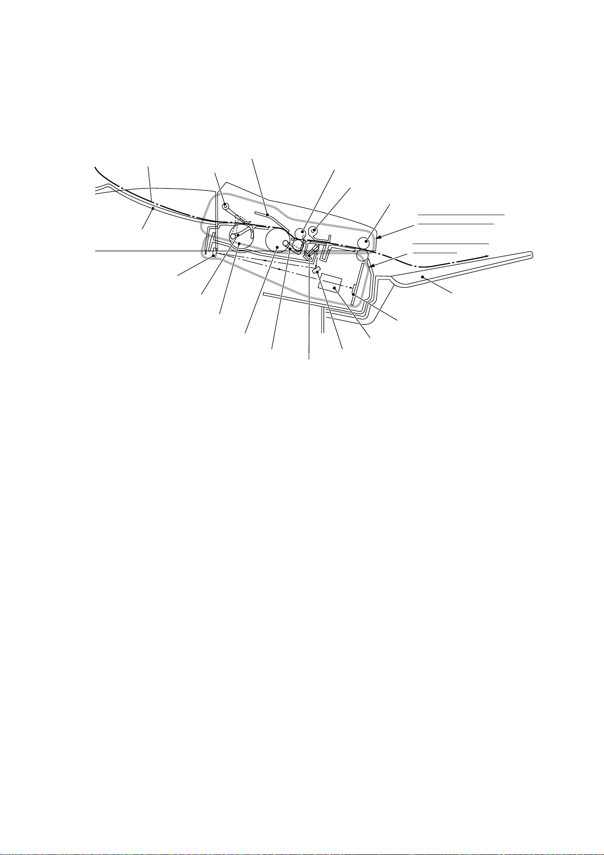
2.1 Scanner Mechanism
Document
Document stacker
2nd mirror
Document front sensor actuator
Document take-in roller ASSY
Separation roller ASSY
Document rear sensor actuator
Nip-related
parts
ADF parts
LED array
2.1.1 Document feeding and ejecting mechanism
Document feed roller ASSY
Document pressure bar
Document ejection roller ASSY
Document feeding and
ejecting mechanism
Document scanning
mechanism
CCD unit
Lens
1st mirror
Document tray
(Front)
This mechanism consists of the document stacker, automatic document feeder (ADF), document feed roller ASSY, and document sensors. (For details about the sensors, refer to Section 2.3.)
If the operator sets documents on the document stacker and starts the scanning operation,
the scanner motor rotates so that the ADF (which consists of the document take-in roller
ASSY, separation roller ASSY, ADF parts and nip-related parts) feeds those documents into
the equipment, starting from the bottom sheet to the top, page by page. Each document
advances with the document feed roller ASSY to the scanner, and then it is fed out of the
equipment with the document ejection roller ASSY.
2.1.2 Document scanning mechanism
The scanner uses a charge coupled device (CCD) image sensor.
As illustrated above, the LED array illuminates a document and the reflected light of the
scanned image data is transmitted via the mirrors into the lens which reduces the scanned
data so as to form the image on the CCD.
III – 3
Page 23
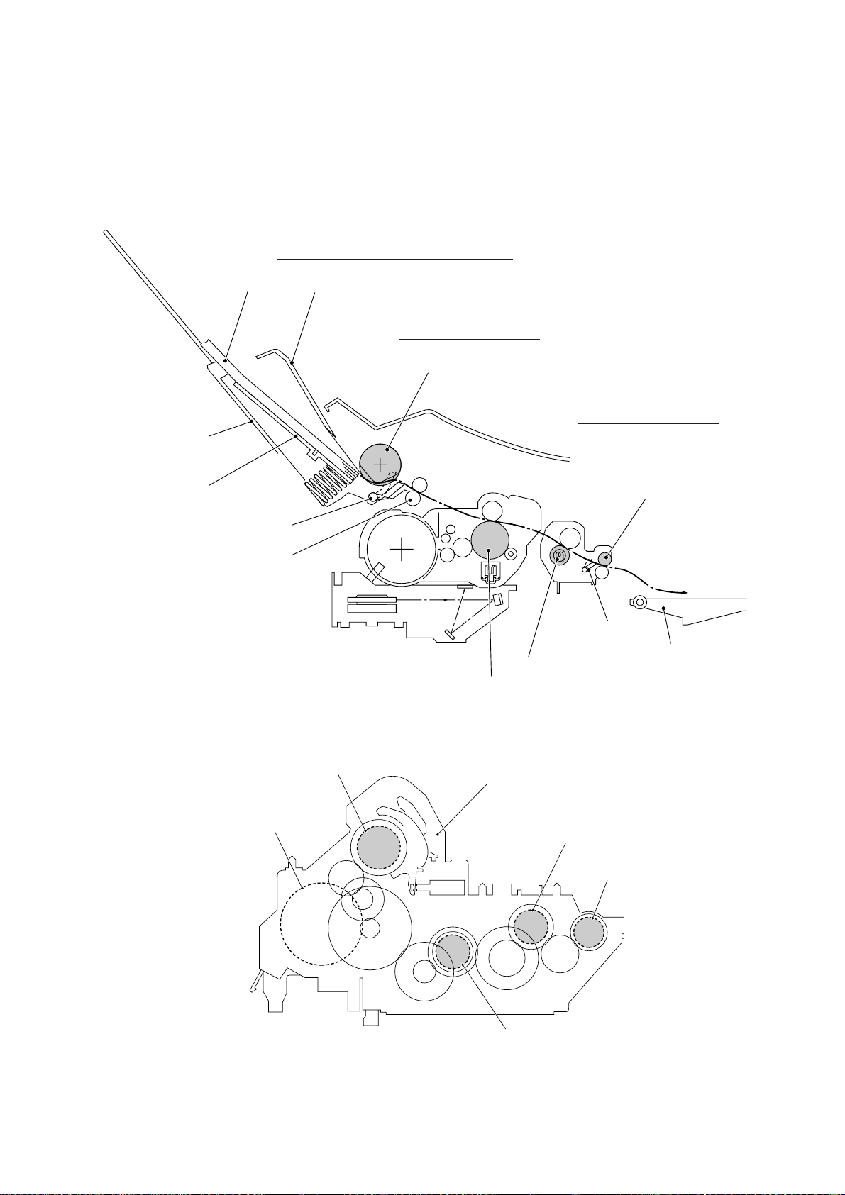
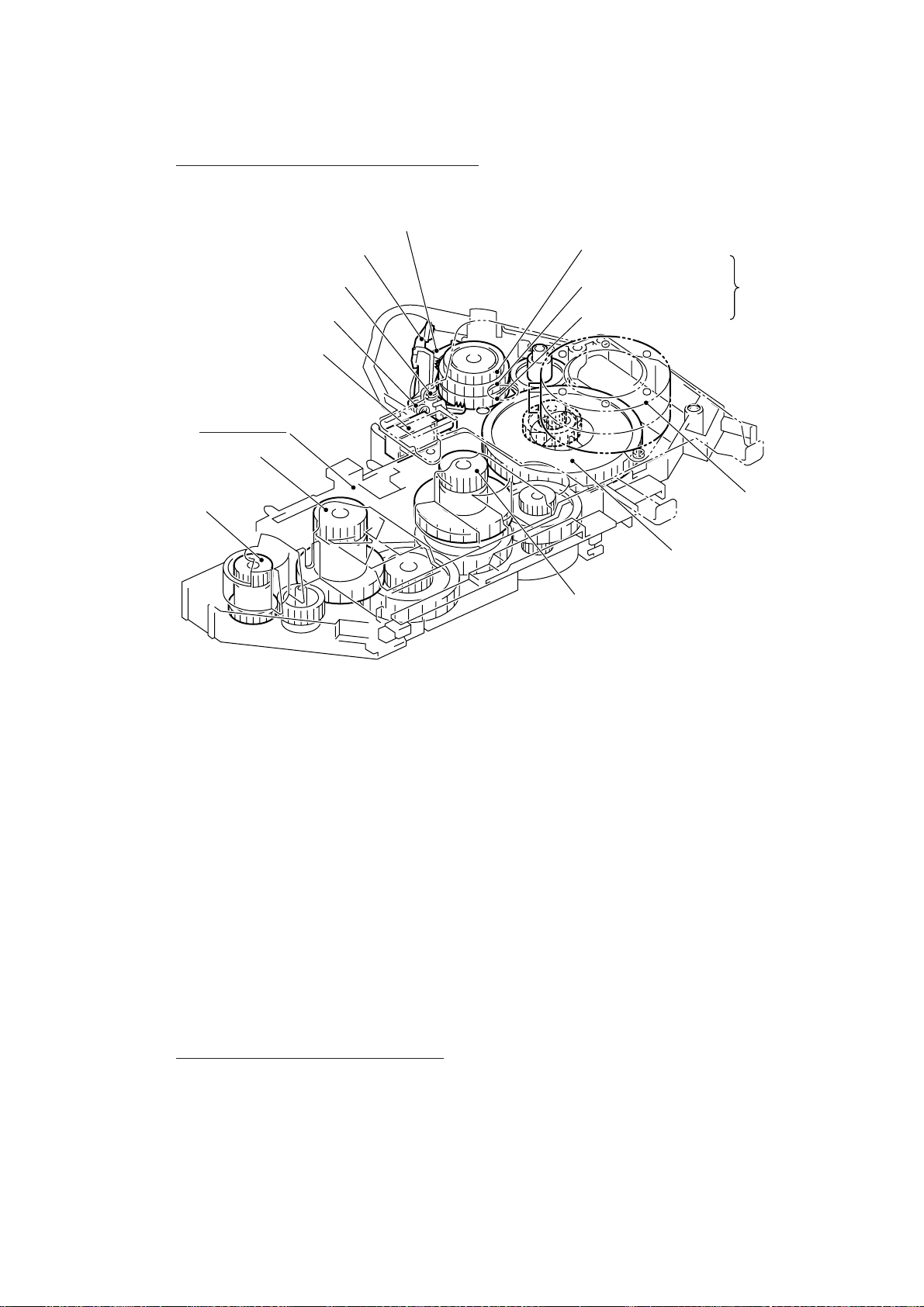
2.2 Laser Printing Mechanism
2.2.1 Paper pulling-in, registration, feeding, and ejecting mechanism
Paper pulling-in and registration mechanism
Paper
Multi-purpose
sheet feeder
Hopper
Registration sensor actuator
Registration roller
Sheet feeder cover
Paper feeding mechanism
Pull-in roller
Paper ejecting mechanism
Paper ejection roller
Paper ejection
sensor actuator
Paper tray
Heater roller
Laser-sensitive drum
Pull-in roller drive gear
Main motor
Gear drive unit
Heater roller drive gear
Paper ejection
roller drive gear
Drum drive gear
III – 4
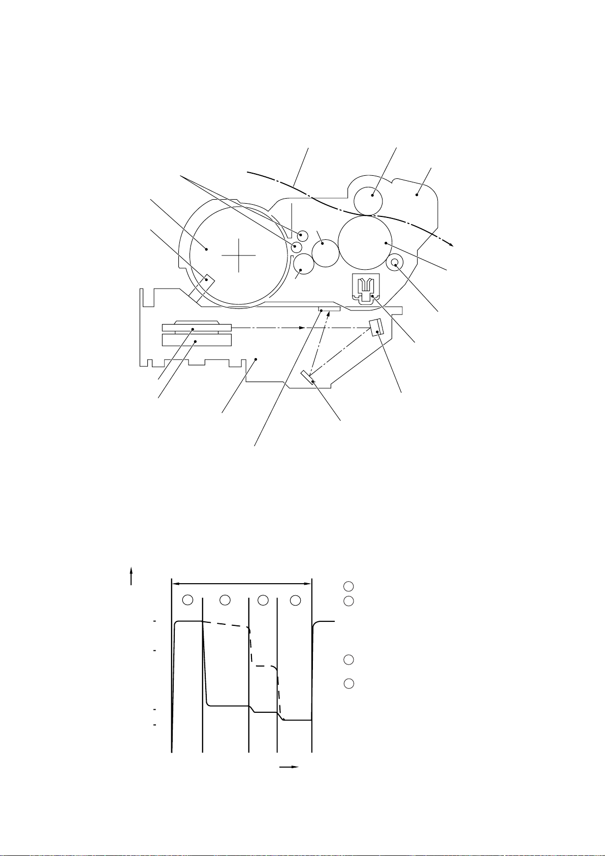
Page 24
Paper pulling-in and registration mechanism
Solenoid lever
Paper feed solenoid
Gear drive unit
Heater roller drive gear
Paper ejection
roller drive gear
Clutch release lever
Solenoid spring
Clutch spring
Pull-in roller drive gear
Intermediate gear
Clutch gear
Gear 20/90
Drum drive gear
Planetary
gear
system
(Front)
Main motor
The paper pulling-in and registration mechanism consists of the pull-in roller gear (incorporated in the multi-purpose sheet feeder), planetary gear system, paper feed solenoid, solenoid lever, clutch release lever, and registration sensor. (For the details about the sensor,
refer to Section 2.3.)
If the main motor rotates clockwise, the rotation is transmitted to the intermediate gear of the
planetary gear system. As the intermediate gear rotates, the pull-in roller drive gear also rotates since the clutch gear is locked by the solenoid lever and the clutch release lever. Accordingly, the pull-in roller in the multi-purpose sheet feeder rotates to pull in paper into the
equipment, a sheet at a time.
If the paper feed solenoid is retracted and the clutch release lever is operated according to
the cam profile of the pull-in roller gear so as to release the clutch gear, the clutch gear rotates and the pull-in roller drive gear does not rotate. In this way, the clutch gear switches
the transmission of the motor rotation on and off to the pull-in roller drive gear.
The solenoid on/off timing and the clutch release lever timing allow this mechanism to pull in
a sheet and register it against the registration roller.
Paper feeding and ejecting mechanism
If the main motor rotates clockwise, the rotation is transmitted via the gear train to the drum
drive gear, heater roller drive gear, and paper ejection roller drive gear.
After the paper passes through the heat-fixing process, it will be ejected onto the paper tray.
If the leading edge of the paper pushes up the actuator of the paper ejection sensor, the
photo sensor becomes opened, signaling the start of paper ejection. If the trailing edge has
passed through the sensor actuator, the sensor becomes closed, signaling the completion of
paper ejection. Then, the main motor stops rotation.
III – 5
Page 25
2.2.2 Print process mechanism
Toner augers
Toner cartridge
Toner sensor
Polygon mirror
Polygon motor
Laser unit
Paper
Developer
roller
Toner supply
roller
Transfer roller
Drum unit
Laser-sensitive drum
Cleaner roller
Charger (Corona wire)
Mirror
Mirror
Cover glass
The print process unit works with laser beam, electrical charges, and toner. The graph below shows the transition of electrical charge on the surface of the laser-sensitive drum
through the five processes: charging, exposing, developing, transferring, and erasing processes.
A single cycle of laser-sensitive
drum operation
1 Charges the drum surface positively .
1
+1000
+700
+400
+300
Electrical charge on the drum surface (V)
(a)
(b)
2
3
4
2 Exposes the drum surface to a laser beam to
form a latent image and develops the latent
image with toner.
(a) Unexposed area (Non-image area)
(b) Exposed area (Image area)
3 Transfers the toner-formed image from the
drum to paper.
4 Erases the residual potential.
Time
III – 6
Page 26
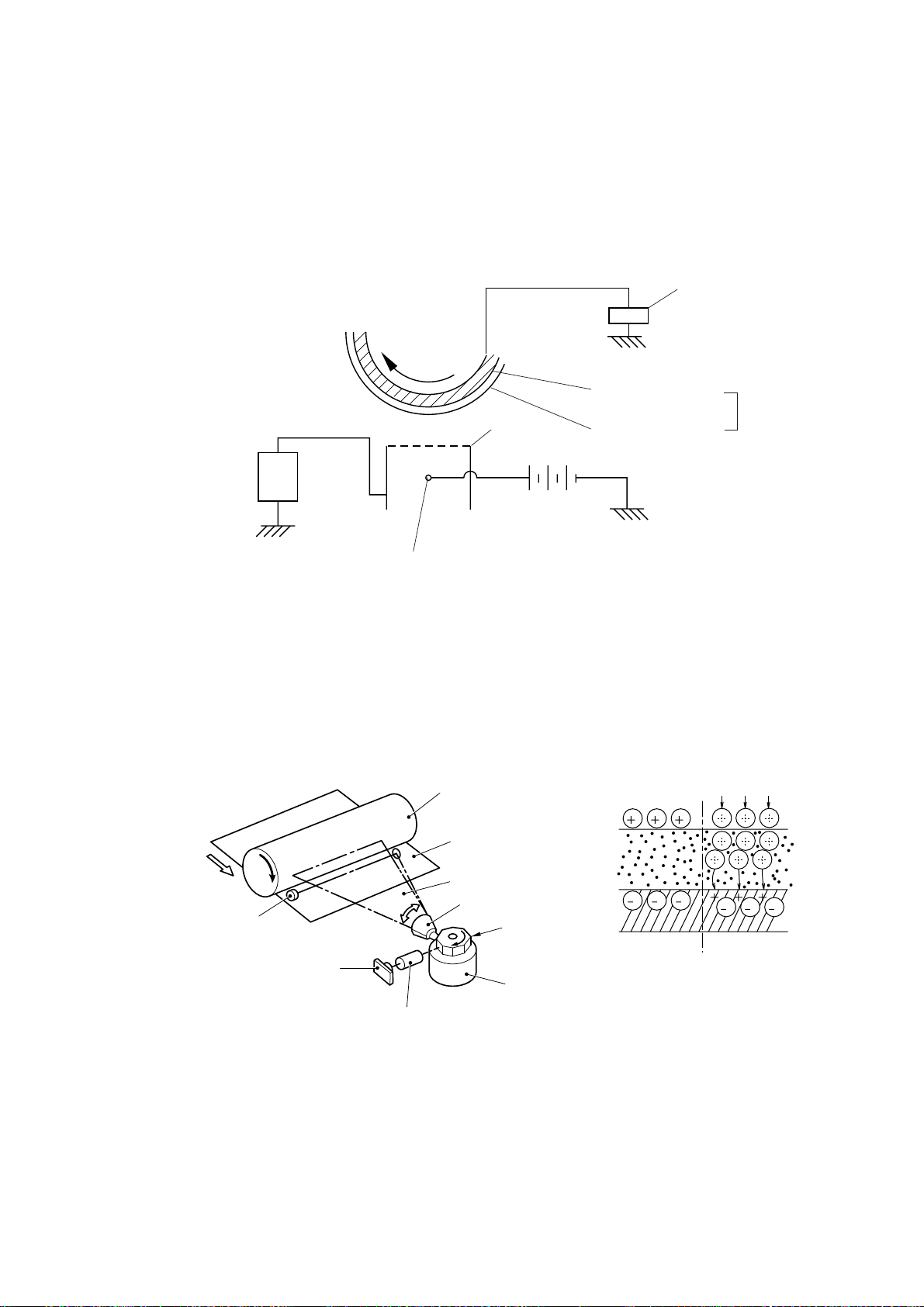
(1) Charging process
The high-voltage power supply applies DC bias to the corona wire to generate ion on the
grid. The ion uniformly charges the surface of the laser-sensitive drum to approx. 1000V
which is kept by the varister grounding the grid to the frame.
Varister
+
+
+
Approx. 1000V
Approx. 280V
-
-
-
-
-
+
+
-
-
-
---
+
+
+
+
+
+
+
Corona wire
+
+
+
+
+
+
+
+
+
Grid
High-voltage
power source
Aluminum drum
Laser-sensitive layer
Positive charging
source
Drum
(2) Exposing process
When the laser-sensitive drum holds a positive electrical charge, the laser beam issued from
the laser unit scans the drum according to the print image to expose the drum surface for
neutralizing the spots where black should be, forming an electrostatic latent image.
Laser detector
Laser diode
Laser-sensitive drum
Paper
Laser beam
f θ lens
Lens
Laser beam
Polygon mirror
Polygon motor
III – 7
Page 27
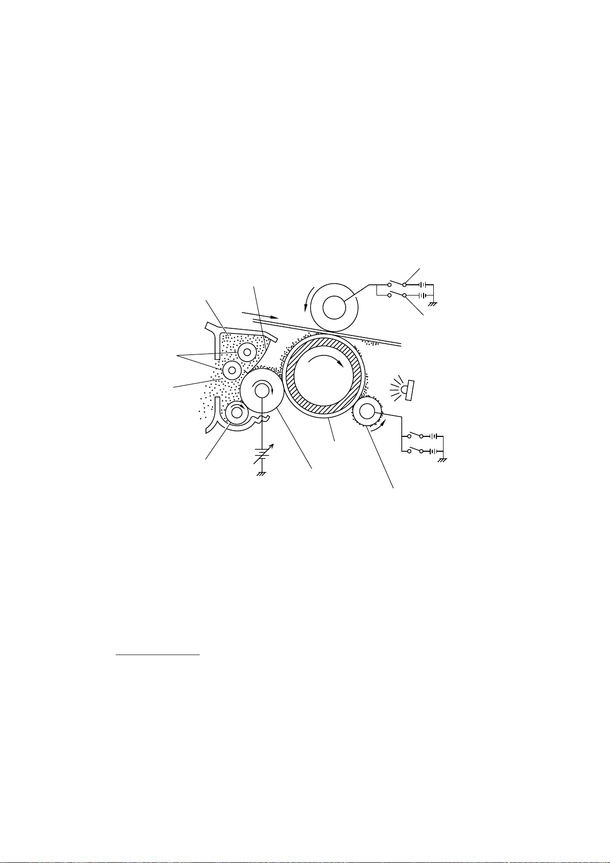
(3) Developing process
The developing process develops an electrostatic latent image formed on the drum in the
exposing process, into a toner image.
The developer roller attracts the toner particles fed from the toner cartridge by the toner supply roller, and then conveys them to the contact section with the laser-sensitive drum.
On the contact section between the developer roller and drum, the positive toner particles
stick to the neutralized spots on the drum according to the principles of attraction and repulsion, transforming a latent image into a toner image.
The toner augers (which agitate toner particles in the chamber) and the blade allow toner
particles to be fed onto the developer roller at an even thickness.
Switch “a” (ON for the
transfer process)
Switch “b” (ON for repulsing
toner from the transfer roller)
Toner augers
Chamber
Blade
Transfer roller
Toner
Toner supply roller
DC bias
Laser-sensitive
drum
Developer
roller
Eraser lamp
Cleaner roller
(4) Transferring process
When a paper passes between the drum and the transfer roller, the switch “a” (see the
above illustration) is turned on to negatively charge the transfer roller. The toner is positive,
so the toner image formed on the drum will be transferred onto the paper according to the
same principle as for the developing process.
If the toner image fails to stick to the paper due to paper jam or other errors, it will stick to the
transfer roller. To repulse this toner, the switch “b” (see the above illustration) is turned on to
positively charge the transfer roller. The toner returns from the transfer roller to the drum.
Cleaning the drum
In the transferring process, not all the toner particles on the drum are transferred onto the
paper but some toner particles remain on the drum. The cleaner roller cleans the drum surface and collects the residual toner. When printing starts or during non-printing, the toner
collected on the cleaner roller will be discharged onto the drum and returned to the chamber
through the developer roller for recycling in the subsequent developing process.
(5) Erasing process
The eraser lamp emits light to expose the drum surface, which erases the residual electrical
charge.
III – 8
Page 28

2.2.3 Heat-fixing mechanism
Pressure roller
Heater roller
(including the FU lamp)
Heat-fixing unit
(Paper ejection roller)
Paper
(Paper ejection sensor actuator)
As the paper passes between the heater roller and the pressure roller in the fixing unit, the
heater roller fuses the toner on the paper.
III – 9
Page 29

2.3 Sensors and Actuators
This equipment has ten sensors: two microswitches, six photosensors and two thermisters
as described below.
Sensor name Type Located on
Hook switch sensor Microswitch Hook switch PCB
Cover sensor Microswitch Relay PCB
Registration sensor Photosensor (PC1) Relay PCB
Sheet feeder cover sensor Photosensor (PC2) Relay PCB
Paper ejection sensor Photosensor (PC1) High-voltage power supply PCB
Document front sensor Photosensor (PC1) Document sensor PCB
Document rear sensor Photosensor (PC2) Document sensor PCB
Toner sensor Photosensor (PH1) Toner sensor PCB (on the laser unit)
Toner thermister P1 Toner sensor PCB (on the laser unit)
Heater thermister __ Fixing unit
• Hook switch sensor which detects whether the handset is placed on the handset mount.
• Cover sensor which detects whether the top cover is closed.
• Registration sensor which detects the leading and trailing edges of paper, which allows
the controller to determine the registration timing and check paper jam.
• Sheet feeder cover sensor which detects whether the sheet feeder cover is closed.
• Paper ejection sensor which detects whether the recording paper goes out of the equipment.
• Document front sensor which detects the presence of documents.
• Document rear sensor which detects the leading and trailing edges of pages to tell the
control circuitry when the leading edge of a new page has reached the starting position
and when the scan for that page is over.
• Toner sensor which detects whether there is toner or a toner cartridge is loaded.
• Toner thermister which detects the temperature of the toner cartridge.
• Heater thermister which detects the temperature of the heater roller of the fixing unit.
These photosensors are a photointerrupter consisting of a light-emitting diode and a lightsensitive transistor. Each of them has an actuator separately arranged as shown on the next
page.
III – 10
Page 30
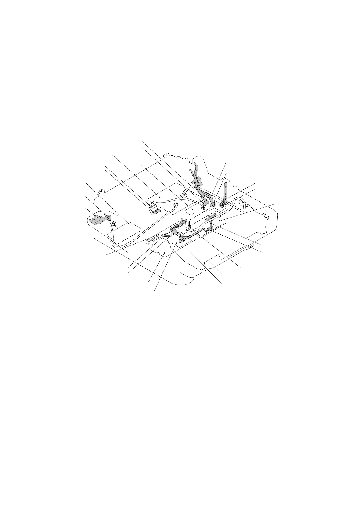
Registration sensor actuator
Registration sensor (Photosensor)
(Main PCB)
Toner thermister
(On back of PCB)
Toner sensor
(Low-voltage power
supply PCB)
Hook switch sensor
(Microswitch)
Hook switch sensor
actuator
(Eraser lamp board)
Document front sensor actuator
Document front sensor (Photosensor)
(Document sensor PCB)
(Relay PCB)
(Toner
sensor
PCB)
(Fixing unit)
Sheet feeder cover sensor actuator
Sheet feeder cover sensor
(Photosensor)
Cover sensor actuator
Cover sensor (Microswitch)
(High-voltage power
supply PCB)
Paper ejection sensor
actuator
Paper ejection sensor
(Photosensor)
Heater thermister
Document rear sensor actuator
Document rear sensor
(Photosensor)
Location of Sensors and Actuators
III – 11
Page 31

3. CONTROL ELECTRONICS
3.1 Configuration
The configuration of the facsimile equipment is shown below.
Centronics parallel
interface (MFC4450/
4550/4550plus/
6550MC/7550MC/
7650MC/9000/9500)
Modular
connector for
PC interface
(FAX3550/3650/
8000P/8200P)
Extended RAM
connector
P15
P1
8-pin
Main PCB
P2
40-pin
36-pin
ASIC
MODEM
Control
panel
PCB
5-pin
P5
P13
26-pin
P18
P9
P8
P7
Relay
PCB
2-pin
4-pin
2-pin
5-pin
1
*
5-pin
P3
5-pin
P2
P4
12-pin
4-pin
P1
Low-voltage
power supply
PCB
Laser unit
Laser diode
Polygon motor
Toner sensor PCB *
3
High-voltage
*
power supply PCB
Fan 2
Main motor
Solenoid
2
3-pin
Eraser lamp board
4-pin
Heater thermister
Heater (FU lamp)
LASER PRINTING
UNIT
Fan 1
Fixing
Unit
AC line
Extended I/O
connector
(MFC6550MC/
7550MC/7650MC/
P3
30-pin
P4
11-pin
9000/9500)
P10
P16
P6
P11
*1On the relay PCB are these sensors:
• Cover sensor
• Sheet feeder cover sensor
• Registration sensor
*2On the toner sensor PCB are these sensors:
• Toner sensor
• Toner thermister
3
*
On the high-voltage power supply PCB is the paper
ejection sensor.
6-pin
2-pin
(Note)
2-pin
Document
sensor PCB
Speaker
NCU PCB
Hook switch
PCB
4
*
SCANNER
UNIT
LED array
CCD unit
Scanner
motor
Line
External TEL
Handset
5
*
4
On the document sensor PCB are these sensors:
*
(Note)
12-pin: U.S.A. versions
18-pin: European and Asian
versions
• Document front sensor
• Document rear sensor
5
*
On the hook switch PCB is the hook switch sensor.
Configuration
III – 12
Page 32

3.2 Main PCB
The main PCB, which is the nucleus controlling the entire operation of the equipment, consists of a FAX engine (ASIC), memories, MODEM, motor drive circuits, sensor detection circuitry, and analog circuits for scanning, printing, and power transmission shifting.
Main PCB
(MFC4450/
4550/4550plus/
6550MC/7550MC/
7650MC/9000/9500)
Modular
connector for PC interface
(RS-232C)
(FAX3550/3650/8000P/8200P)
ROMs
DRAM(s)
Extended RAM
connector
Centronics
parallel interface
E2PROM(s)
ASIC
Main motor
driver
Image
processor
Scanner
motor driver
Control panel
Relay PCB
Fan 2
Main motor
Solenoid
Low-voltage
power supply
PCB
Document
sensor PCB
Scanner
motor
Extended I/O
connector for
optional serial
interface board
(RS-232C and
RS-422)
(MFC6550MC/7550MC/
7650MC/9000/9500)
Amplifiers
MODEM
E2PROM: Electrically Erasable Programmable Read-only Memory
DRAM: Dynamic Random Access Memory
Analog switch
operational
amplifiers
Block Diagram of Main PCB
III – 13
Speaker
NCU PCB
Hook switch
PCB
Page 33

1
2
Main PCB Circuit Diagram 1/7
1 FAX engine (ASIC) which manages the I/Os, memories, drivers and image proces-
sor as well as controlling the laser printing unit.
2 8-pin modular connector for the PC interface (RS-232C), provided on the FAX3550/
3650/8000P/8200P.
III – 14
Page 34

1
#12
3
#11
2
4
#2 #3
Main PCB Circuit Diagram 2/7
#15
5
#10
1 FAX3550/3650/8000P/8200P/MFC4450/4550/6550MC/7550MC/9000/9500:
ROM (8-megabit, 512K x 16 bits) which stores programs.
MFC4550plus/7650MC: Flash ROM (8-megabit) which stores programs.
2 ROM (8-megabit, 512K x 16 bits)
FAX3550/3650/8000P/8200P/MFC4450/4550/4550plus:
This ROM is used only on the qualification machines for demonstration.
MFC6550MC/7550MC/7650MC/9000/9500:
This ROM stores the PCL4 (Driver programs for high-quality print).
3 DRAMs
FAX3550/8000P/MFC4550/6550MC/7550MC/9000/9500:
DRAM No.
Model
FAX3550/MFC4550 –– 4M x 8 bits 4M x 8 bits ––
FAX8000P/MFC6550MC/ –– 4M x 8 bits 4M x 8 bits ––
9000/9500
MFC7550MC –– –– –– 16M x 16 bits
#10 #11 #12 #15
FAX3650/8200P/MFC4450/4550plus/7650MC:
DRAM No.
Model
FAX3650/8200P –– 16M x 16 bits
MFC4450 4M x 16 bits 4M x 16 bits
MFC4550plus 4M x 16 bits 4M x 16 bits
MFC7650MC –– 16M x 16 bits –– : Not installed
#10 #15
6
–– : Not installed
III – 15
Page 35

4 E2PROMs which store user settings.
FAX3550/8000P/MFC4550/6550MC/7550MC/9000/9500:
E2PROM No.
Model
FAX3550 16K x 1 bit 16K x 1 bit
MFC4550 –– 16K x 1 bit
MFC6550MC –– 16K x 1 bit
FAX8000P/MFC6550MC/ 16K x 1 bit 16K x 1 bit
9000/9500
#2 #3
–– : Not installed
FAX3650/8200P/MFC4450/4550plus/7650MC:
E2PROM No.
Model
FAX3650/8200P 16K x 1 bit 16K x 1 bit
MFC4450 –– 16K x 1 bit
MFC4550plus –– 16K x 1 bit
MFC7650MC –– 32K x 1 bit
#2 #3
–– : Not installed
5 Extended RAM port which allows you to add a memory up to two megabytes.
6 Extended I/O connector for an optional serial interface board RS-100M which supports
the RS-232C and RS-422. (Only for the MFC6550MC/7550MC/7650MC/9000/9500)
III – 16
Page 36

1
2
1-1
1-2
1-3
1-4
1-5
3
Main PCB Circuit Diagram 3/7
1 Connector for the document sensor PCB
1-1: Current sink transistor for driving the LED array
1-2: Synchronous clocks for the CCD unit
1-3: Image signal from the CCD unit
1-4: Signal from the document front sensor
1-5: Signal from the document rear sensor
2 Connector for the control panel
3 Image signal processor
FAX3550/3650/8000P/8200P/MFC4450/4550/4550plus: 200 dpi
MFC6550MC/7550MC/7650MC/9000/9500: 300 dpi
III – 17
Page 37

1-1
2
1-2
1 Operational amplifiers for modem-to-line interface
2 Modem
3 Short pin
1
Main PCB Circuit Diagram 4/7
1-1: RIN, signal from line to modem
1-2: TXO, signal from modem to line
Mounted on the Turkish versions only.
3
III – 18
Page 38

1
3
1-1
1-2
1-3
1-4
1-5
1-6
1-7
1-8
1-9
1-10
1-11
5
2
6
4
7
8
Main PCB Circuit Diagram 5/7
1 Connector for the relay PCB
1-1: Laser drive signals
1-2: High-voltage power supply control signals
1-3: Eraser lamp ON/OFF signal
1-4: Fan 1 control signal
1-5: Signal input from the paper ejection sensor
1-6: Signal input from the registration sensor
1-7: Signal input from the sheet feeder cover sensor
1-8: Signal input from the cover sensor
1-9: Signal input from the toner sensor
1-10: Signal input from the heater thermister
1-11: Signal input from the toner thermister
2 Heater control circuit which prevents the heater from overheating due to ASIC or soft-
ware malfunction. (The ASIC controls the HTON signal with the hysteresis characteristics for stabilized heater control.)
3 Connector for the low-voltage power supply
4 Main motor driver which controls recording paper feeding and drum rotation.
5 Fan 2 driver circuit
6 Paper pull-in solenoid circuit
7 Scanner motor driver and its control circuitry
8 Signal input from the hook switch
III – 19
Page 39
1
2-1
2
2-2
Main PCB Circuit Diagram 6/7
1 Centronics parallel interface circuitry (for the MFC4450/4550/4550plus/6550MC/
7550MC/7650MC/9000/9500)
Connector P15 is compatible with the standard Centronics parallel interface.
2 Backup circuit for the calendar clock of the control panel
2-1: For FAX3550/3650/8000P/8200P/MFC4450/4550/4550plus/9000
2-2: For MFC6550MC/7550MC/7650MC/9500 (This circuit backs up also the im-
age and voice data.)
III – 20
Page 40

1
2-2
2-1
3
3-1
2
2-3
Main PCB Circuit Diagram 7/7
1 Connector for the NCU PCB
CMLL: NCU relay ON/OFF signal
PLS: Dial pulse output
TLOF: Off-hook signal which is active Low for the external telephone.
CI: Call signal which is active Low.
TXD: Line output signal from the MODEM
TLSL: Handset microphone signal
RL1: Line input signal to the MODEM
RL2: Line monitor signal
ADLC: Line current detection input
DASEND: Output level matching signal
DAST: Side tone level matching signal (Only in the European versions.)
DPS: External telephone switching signal
EAT: Earth function signal
POL: Polarity inversion detection signal
2-7
2-4
2-6
4-2
4-1
2-5
3-2
4
III – 21
Page 41

2 Switching devices that are controlled by the ASIC
2-1: Device TEL. If 0, the equipment works as a telephone; if 1, it sends a fac-
simile message.
2-2: Device HSPLY. If 0, the equipment works as a telephone; if 1, it plays back
a TAD recorded message.
2-3: Device TADH. If 0, the equipment works regularly; if 1, it allows you to
record a message through the microphone.
2-4: Device CMLH. If 0, the equipment is placed in monitor mode; if 1, it is nor-
mally connected to the line.
2-5: Device RNG. If 0, the speaker rings; if 1, it transfers control to the device
MSL.
2-6: Device MSL. If 0, the speaker works for converting line signals to sound; if
1, it works for playing back a TAD recorded message.
2-7: Device MUTE that mutes the receiver tone.
3 Speaker amplifiers
3-1: For FAX3550/3650/8000P/8200P/MFC4450/4550/4550plus/9000
3-2: For MFC6550MC/7550MC/7650MC/9500
4 Speaker volume control circuitry
4-1: VOL1 that controls the speaker volume to two levels: High and Low.
4-2: VOL2 that augments VOL1 to handle four levels: High, Medium-high, Me-
dium-low, and Low. (MFC6550MC/7550MC/7650MC/9500 only)
III – 22
Page 42

3.3 Relay PCB
1
4
2
3
8
7
5
6
9
Relay PCB Circuit Diagram
1 Connector for the main PCB
2 Registration sensor (PC1) circuit
3 Sheet feeder cover sensor (PC2) circuit
4 Cover switch (SW1)
5 Connector for the high-voltage power supply PCB
6 Connector for the toner sensor PCB
7 Connector for the laser diode of the laser unit
8 Switching circuit which feeds 24V power to the polygon motor during the printing pro-
cess.
9 Connector for the polygon motor
III – 23
Page 43

3.4 NCU PCB
The NCU PCB switches the communications line to telephone or built-in MODEM, under the
control of the main PCB.
2
1
3
4
5
6
2
2
9
7
A
8
:
NCU PCB Circuit Diagram (U.S.A. versions)
1 Surge absorber
2 Noise filters
3 Line relay (CML relay)
4 Line transformer
5 Circuit related to the line transformer
6 High-impedance transformer circuit
7 Calling signal detector
8 Loop current detector
9 Dial pulse generator
: Telephone circuit
A Reference voltage generation circuit for the operational amplifier in ⑤.
III – 24
Page 44

1
2
2
8
3
4
5
2
2
2
2
2
B
3
6
C
9
7
A
:
NCU PCB Circuit Diagram (European versions)
1 Surge absorber
2 Noise filters
3 Line relay (CML relay)
4 Line transformer
5 Circuit related to the line transformer
6 High-impedance transformer circuit
7 Calling signal detector
8 Loop current detector
9 Dial pulse generator & loop current detector
: Telephone circuit
A Reference voltage generation circuit for the operational amplifier in ⑤.
B Pulse shaper
C Line current detection input circuit
III – 25
Page 45

• The primary function of the NCU (which is shared by facsimile and telephone units) is to
switch a line to the facsimile unit or to the telephone, which is carried out by the line relay.
• Since the direct connection of a facsimile equipment to the line is not allowed for protect-
ing the line, it is essential to insert a line transformer between the line and the facsimile
equipment to insulate them from each other in the direct current band.
The above two components, line relay and line transformer, are the minimum requirements
for the NCU of the facsimile equipment.
• If an external telephone is connected to the facsimile equipment, the NCU should have a
loop current detector to identify the hook state by detecting the loop current.
• If the facsimile equipment has an automatic answering facility (TAD), the NCU should be
equipped with a calling signal detector which detects a calling signal and tells it to the
CPU in the FAX engine (ASIC).
• The circuit related to a line transformer allows the line transformer to be invariant by se-
lecting the constants of the parts in this circuit so as to conform to the communications
regulations or codes of each country.
In addition to the above basic components of the NCU, the following components are also
required depending upon additional functions of the facsimile equipment:
• The dial pulse generator generates dial pulses within the facsimile equipment.
• The surge absorber is a protection circuit which absorbs lightning surges.
• The noise filter eliminates noise including radiation noise in order to prevent them from
flowing out onto the communications line.
• The high-impedance transformer circuit detects the remote activation, and F/T switching
sent from the line in ON-HOOK state without any interference to the line.
• The telephone circuit includes an amplifier that amplifies output signals of the handset mi-
crophone. It also includes a transistor that amplifies receive signals from the communications lines to sound the handset receiver.
III – 26
Page 46

3.5 Control Panel PCB
The control panel PCB and the main PCB communicate with each other by serially transmitting commands and data.
The control panel unit consists of a gate array, an LCD, and LEDs, which are controlled by
the gate array according to commands issued from the FAX engine on the main PCB.
The calendar clock is backed up by the backup circuit on the main PCB.
The panel FPC is a flexible keyboard PCB which integrates the key matrix having rubber
keytops.
FAX
Engine
+5B
+5V
Backup
Circuit
Main PCB
SDIN
SDOUT
PCLK
Control Panel PCB and its Related Circuit
Control Panel PCB
Serial
Communications
Ports
+5V
Reset
Circuit
POWER
RESET
Gate Array
I/O Ports
LCD
Panel FPC
(Key Matrix)
LED
S
III – 27
Page 47

3.6 Power Supply PCBs
[ 1 ] Low-voltage power supply PCB
The low-voltage power supply uses the switching regulation system to generate DC power
(+5V and +24V) from a commercial AC power supply for the driver circuits. The +5V source
is fed to the logic, control panel, sensors, CCD unit, etc.; the 24V source is fed to the motors,
solenoid, fans, LED array, and the high-voltage power supply PCB.
The low-voltage power supply also feeds AC power to the heater of the fixing unit.
(Heater)
Fuse
Line
Filter
Lightning
Surge
Absorber
Rectifier
Thermal
Fuse
Heater
Circuit
FU lamp
Feedback
Switching
Circuit
24V
Detector
5V
Regulation
Circuit
Low-voltage Power Supply Circuit
III – 28
(Driver circuits)
24V
5V
Page 48

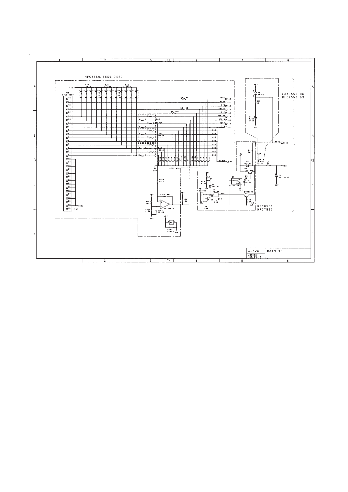
[ 2 ] High-voltage power supply PCB
This power supply generates high-voltage power sources from the 24V source fed from the
low-voltage power supply for charging, developing, and transferring in the laser printing process.
Fuse Type Resistor
R1
11
24VI
Control 1
(TIDN TAIDEN)
Control 2
(GENZ GENZOU)
Control 3A
(TENH TESHAH)
0.22
1/6w
6
7
10
Current
Regulator
(250µA)
B1 Q1
Voltage
Regulator
(600 ± 10V)
(275 ± 7V)
VR33 VR31 VR34
Current
Regulator
(-3.0µA)
OUT1
OUT2
OUT3
Developer
Roller
Transfer Roller
Laser-sensitive
Drum
Cleaner Roller
Grid
Corona Wire
Control 3B
(TENL TESHAL)
GND
VCLN
B51 Q51
Voltage
9
12
8
Regulator
(1.8kV)
Q56
B52
Voltage
Regulator
(1.0kV)
VR201
Voltage
Regulator
(275V)
VR101
Voltage
Regulator
(700V)
VR32
VR53
910
Z201
GRID
DRMBIAS
VCLN
High-voltage Power Supply Circuit
III – 29
Page 49

CHAPTER IV.
DISASSEMBLY/REASSEMBLY
AND LUBRICATION
Page 50

CONTENTS
1. DISASSEMBLY/REASSEMBLY.................................................................... IV-1
■Safety Precautions.................................................................................... IV-1
■Preparation................................................................................................IV-3
■How to Access the Object Component...................................................... IV-3
■Disassembly Order Flow........................................................................... IV-4
1.1 Top Cover...............................................................................................IV-5
1.2 Handset Mount and Hook Switch PCB (for handset-equipped versions)
Side Cover (for non-handset versions)............................................................ IV-5
1.3 Multi-purpose Sheet Feeder.................................................................. IV-6
1.4 Control Panel ASSY.............................................................................. IV-6
1.5 Panel Rear Cover and Control Panel.................................................... IV-7
1.6 Document Feed Roller ASSY and Ejection Roller ASSY...................... IV-8
1.7 Inner Cover............................................................................................IV-8
1.8 Scanner Frame ASSY........................................................................... IV-10
1.9 Insulation Cover.................................................................................... IV-12
1.10Fixing Unit, FU Lamp, and Paper Ejection Sensor Actuator.................. IV-13
1.11Laser Unit...............................................................................................IV-15
1.12Bottom Plate..........................................................................................IV-16
1.13Low-voltage Power Supply PCB........................................................... IV-17
1.14High-voltage Power Supply PCB and Fan 1......................................... IV-18
1.15Main PCB...............................................................................................IV-19
1.16Relay PCB.............................................................................................IV-21
1.17Shield Bracket and NCU PCB ASSY.................................................... IV-22
1.18Gear Drive Unit......................................................................................IV-23
1.19Duct Cover, Fan 2, and Speaker........................................................... IV-25
1.20Sheet Feeder Cover Sensor Actuator, Registration Sensor Actuator,
and Cover Sensor Actuator................................................................... IV-26
1.21Microphone (MFC9500 only)........................................................................... IV-27
1.22Cleaning of High-voltage Contacts and Grounding Contacts................ IV-28
1.23Harness Routing................................................................................... IV-29
2. LUBRICATION................................................................................................IV-30
Page 51

1. DISASSEMBLY/REASSEMBLY
■ Safety Precautions
To prevent the creation of secondary problems by mishandling, observe the following precautions during maintenance work.
(1) Always unplug the power cord before replacing parts or units. When having access to
the power supply, be sure to unplug the power cord from the power outlet.
(2) When servicing the optical system of the laser printing unit, be careful not to place
screwdrivers or other reflective objects in the path of the laser beam. Be sure to take
off any personal accessories such as watches and rings before working on the printer.
A reflected beam, though invisible, can permanently damage your eyes.
(3) If the equipment has been printing, allow the fixing unit sufficient time to cool down. It is
HOT!
(4) Be careful not to lose screws, washers, or other parts removed for parts replacement.
(5) Do not remove gears from the document LF roller ASSY or ejection roller ASSY if at all
possible. Once removed, they will become unusable and new gears will have to be put
back in.
(6) When using soldering irons and other heat-generating tools, take care not to damage
the resin parts such as wires, PCBs, and covers.
(7) Before handling the PCBs, touch a metal portion of the equipment to discharge static
electricity; otherwise, the electronic parts may be damaged due to the electricity
charged in your body.
(8) When transporting PCBs, be sure to wrap them in conductive sheets such as aluminum
foil.
WARNING
For the MFC6550MC/7550MC/7650MC/9000/9500 which has a nickel-hydrogen battery
on the main PCB, be sure to remove that battery before transporting the PCB (in alu-
minium foil). Failure to do so may result in a short circuit, overcurrent flow, or fire.
(9) Be sure to reinsert self-tapping screws correctly, if removed.
(10) Tighten screws to the torque values listed on the next page.
(11) When connecting or disconnecting cable connectors, hold the connector bodies not the
cables. If the connector has a lock, always slide the connector lock to unlock it.
(12) Before reassembly, apply the specified lubricant to the specified points. (Refer to Sec-
tion 2 in this chapter.)
(13) After repairs, check not only the repaired portion but also that the connectors and other
related portions function properly before operation checks.
IV – 1
Page 52

Tightening Torque List
Location Screw type Q'ty Tightening torque (kgf•cm)
Handset mount Taptite, cup B M3x10 2 5 ±1
Hook switch PCB Taptite, cup B M3x6 1 5 ±1
Panel rear cover Taptite, cup B M3x8 2 3 ±1
Inner cover Taptite, cup B 4x12 2 8 ±1
Taptite, cup B 3x10 3 8 ±1
Scanner motor Screw, pan (washer) 3x8DB 1 7 ±2
Fixing unit Taptite, bind B 4x12 1 10 ±1
Taptite, bind B 3x10 2 8 ±1
Laser unit Taptite, bind B 4x12 3 8 ±1
Toner sensor PCB Taptite, cup B 3x8 1 6 ±1
Bottom plate Taptite, cup B 4x12 5 8 ±1
(On the main shield bracket) Taptite, cup S 3x6 2 5 ±1
(On the gear drive unit) Taptite, cup S 3x6 2 8 ±1
Grounding wire Screw, pan (washer) 4x8DB 1 7 ±2
Low-voltage power supply PCB Taptite, bind 4x12 1 10 ±1
High-voltage power supply PCB Taptite, bind 4x12 1 10 ±1
Interface plate Taptite, bind 3x6 3 5 ±1
Relay PCB Taptite, bind B 4x12 1 10 ±1
Shield bracket Taptite, cup B 3x10 3 5 ±1
NCU PCB ASSY Taptite, cup B 3x10 1 5 ±1
Drive unit Taptite, cup B 4x20 3 12 ±1
Taptite, bind B 4x12 1 10 ±1
IV – 2
Page 53

■ Preparation
Prior to proceeding to the disassembly procedure,
(1) Unplug
- the modular jack of the telephone line,
- the modular jack of the curled cord (and remove the handset), and
- the modular jack of an external telephone set if mounted. (Not shown below.)
(2) Remove
- the wire extension,
- the document tray,
- the paper tray, and
- the drum unit (with the toner cartridge loaded).
Handset and curled cord
Drum unit (with toner cartridge loaded)
Wire extension
Document tray
■ How to Access the Object Component
• On the next page is a disassembly order flow which helps you access the object component. To remove the relay PCB, for example, first find it on the flow and learn its number
(F in this case). You should remove parts numbered 1, 3, B, and E so as to access
the relay PCB.
• Unless otherwise specified, the disassembled parts or components should be reassembled in the reverse order of removal.
Telephone line cord
Paper tray
IV – 3
Page 54

■ Disassembly Order Flow
Control panel ASSY
4
bar
Panel rear cover
- Document pressure
- ADF parts
- Nip-related parts
5
Document ejection
6
Control panel
- Control panel PCB
- FPC key
Document feed
6
roller ASSY
Inner cover
7
roller ASSY
Document sensor actuators
Document sensor PCB
Scanner frame ASSY
8
Mirrors
Ejection leaf
Cover sensor
actuator
20
20
Separation roller ASSY
Document take-in roller
ASSY
Scanner motor
Pressure roller
spring
• Sheet feeder
ASSY
cover sensor
actuator
sensor actuator
• Registration
Insulation cover
FU lamp
Fixing unit
9
10
Microphone
(MFC9500 only)
21
Paper ejection sensor actuator
10
Multi-purpose
sheet feeder
3
Bottom plate
12
Main PCB
15
High-voltage
power supply PCB
14
Low-voltage
power supply
PCB
13
Relay PCB
16
Fan 1
14
Shield bracket
17
- Duct cover
- Fan 2
- Speaker
19
Main motor
Gear drive unit
18
NCU PCB ASSY
17
Gears
Solenoids
Top cover
1
Handset mount*
Side cover**
Hook switch PCB*
2
2
Laser unit
11
IV – 4
*For handset-equipped versions
**For non-handset versions
Page 55

1.1 Top Cover
(1) Open the top cover.
(2) Push the arm of the top cover outwards with your thumb to unhook it from the main
cover.
(3) Turn the top cover upright and slide it to the rear.
Top cover
Top cover
turned upright
Arm
Main cover
1.2 Handset Mount and Hook Switch PCB (for handset-equipped versions)
Side Cover (for non-handset versions)
(1) Remove the two screws from the handset mount* or the side cover.**
(2) Twist the handset mount* or the side cover** so that it tilts over to the left and its upper
end works out of the bosses provided on the main cover.
(3) To remove the hook switch PCB*, disconnect the hook switch harness* and remove the
screw.
(Non-handset versions)
Side cover**
Hook switch sensor*
Bosses
(Handset-equipped
versions)
Hook
switch*
Handset
mount*
*For handset-equipped versions
**For non-handset versions
Hook switch PCB*
Hook switch harness*
Main cover
IV – 5
Page 56

1.3 Multi-purpose Sheet Feeder
(1) Pull either one of the right and left tabs provided on the main cover outwards and
slightly lift up the multi-purpose sheet feeder, then release the other end of the sheet
feeder also.
(2) Take up the sheet feeder.
Tab on the
main cover
Multi-purpose sheet feeder
Tab on the
main cover
Boss
■ Reassembling Notes
• To install the sheet feeder, align the right and left end of the front edge with the bosses of
the main cover and then push down the rear.
1.4 Control Panel ASSY
(1) Slightly open the control panel ASSY as shown below.
(2) Push the right and left arms of the control panel ASSY outwards with your thumbs to
unhook them from the bosses provided on the main cover, then slide the control panel
ASSY to the rear.
(3) Disconnect the main-panel harness from the control panel PCB.
Arm of the control panel ASSY
Control panel PCB
Control panel ASSY
Arm
Main-panel harness
IV – 6
Page 57

1.5 Panel Rear Cover and Control Panel
(1) Place the control panel ASSY upside down.
(2) Remove the document pressure bar, ADF parts, and nip-related parts from the panel
rear cover.
(3) Remove the two screws from the panel rear cover.
(4) While lifting up the front edge of the panel rear cover, unhook it from the 15 pawls "X"
provided on the control panel.
(5) Unhook the control panel PCB from the three pawls "Y" on the control panel and take it
out together with the FPC key.
Document pressure bar
Spring plate A
Separation rubber
ADF
parts
Spring plate B
Nip-related parts
Panel rear cover
15 "X" pawls
FPC key
Control panel PCB
Control panel
(placed upside down)
3 "Y" pawls
■ Reassembling Notes
• When installing the spring plate B and separation rubber, align their cutouts with the boss
on the panel rear cover.
IV – 7
Page 58

1.6 Document Feed Roller ASSY and Ejection Roller ASSY
(1) Push arm rib "A" to the rear, then shift the document feed roller ASSY to the right and
upwards.
(2) Push arm rib "B" to the rear, then shift the document ejection roller ASSY to the right
and upwards.
Document feed roller ASSY
"A"
Document ejection roller ASSY
1.7 Inner Cover
(1) Remove the five screws.
(2) Unlatch the pawl "a" by hand.
(3) While lifting up the inner cover, unlatch the four pawls "b" and "c."
NOTE: Take care not to scratch or drop the cover glass on the scanner frame ASSY.
Control panel lock
(Leaf spring)
"B"
Viewed from
the left side
"c"
"c"
Inner cover
"b"
"a"
Sponge
"b"
Pinch rollers
IV – 8
Page 59

■ Reassembling Notes
• Before putting the inner cover on the main cover, make sure that:
- The control panel locks (leaf springs) are set in the inner cover as shown on the previous page.
- The pinch rollers are set with their fringes facing outwards as shown on the previous
page.
- The main-panel harness connector comes out from the cutout provided in the inner
cover as shown below.
Main-panel harness
Inner cover
- After installing the inner cover, be sure to put the sponge back into place.
IV – 9
Page 60

1.8 Scanner Frame ASSY
(1) You can remove the following parts from the top of the scanner frame ASSY without
taking out the ASSY from the main cover:
• Cover glass. Turn the cover glass up towards you.
• Ejection leaf springs. Remove them while slightly pulling up the front edges.
• Document take-in roller ASSY. Unhook the latch of the gear, take it off, and lift up the
ASSY.
• Separation roller ASSY. First unhook the latch of the adjacent gear and take it off,
and then remove the separation roller ASSY in the same way as for the document
take-in roller ASSY.
• Pressure roller ASSY. While pressing down the leaf springs, remove the ASSY.
• Bar lens and LED array.
• Document front sensor actuator.
• Document rear sensor actuator. While pressing down the leaf spring and pulling the
boss "X" provided on the scanner frame ASSY to the front, slightly move the actuator
to the left and lift it up.
• Document sensor PCB. Disconnect the CCD harness and LED array harness from
the document sensor PCB. Take the main-sensor harness out of the three clamps
(see the illustration on the next page) and then disconnect it from the PCB.
Document take-in
roller ASSY
Document rear
sensor actuator
Document front
sensor actuator
Separation roller ASSY
Pressure roller ASSY
Cover glass
Document
sensor PCB
Boss "X"
PC1
P1
P2
PC2
P3
PC1: Document front sensor
PC2: Document rear sensor
Leaf springs
Bar lens and LED array
CCD unit
(Do not remove)
Ejection leaf
springs
(Front)
CCD harness
Main-sensor harness connector
CCD harness connector
IV – 10
Page 61
(2) Before taking out the scanner frame ASSY, make sure that the cover glass is removed
and the main-sensor harness is disconnected.
(3) Slightly lift up the scanner frame ASSY and disconnect the scanner motor harness from
the motor, then take out the ASSY.
NOTE: Take care not to scratch the mirrors (see the illustration below), CCD unit, or
bar lens.
NOTE: NEVER remove or replace the CCD unit. Its mounting position has been ad-
justed in the factory.
Document
sensor PCB
Main-sensor harness
Clamps
Cover glass
(Remove before taking out the scanner
frame ASSY .)
Bar lens and LED array
Scanner frame ASSY
Sponges
Sponge
CCD unit
(Do not remove)
Scanner motor harness
Scanner motor
Mirrors
(Front)
IV – 11
Page 62

■ Reassembling Notes
• Check that the mirrors and cover glass are not stained. Wipe them with a soft cloth if
necessary.
• If you have disassembled the gear train on the right side of the scanner frame ASSY, reassemble it referring to the illustration below.
Separation roller gear
Document take-in
roller gear
(Front)
• After installing the scanner frame ASSY, be sure to put the sponges back into place as
shown on the previous page.
1.9 Insulation Cover
(1) Lift up the insulation cover.
(Rear)
Scanner frame
ASSY
Scanner motor gear
(Right side view)
Insulation cover
IV – 12
Main cover
Page 63

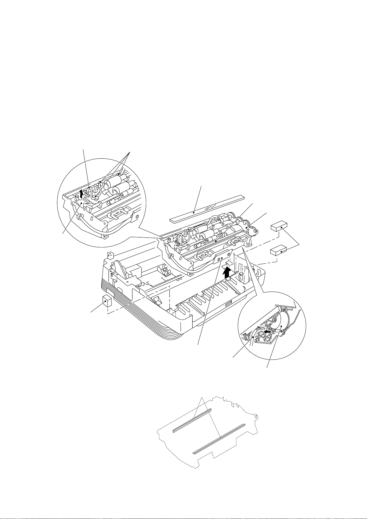
1.10 Fixing Unit, FU Lamp, and Paper Ejection Sensor Actuator
(1) Remove the screw "a."
(2) Lift up the fixing unit and then disconnect the heater harness (blue and brown wires).
Disconnect the heater thermister harness from the eraser lamp board.
Fixing unit
Eraser lamp
board
Blue heater
harness
Brown heater
harness
"a"
Paper ejection
sensor actuator
Heater thermister harness
"b"
"b"
Paper ejection
sensor actuator
(3) Remove the paper ejection sensor actuator from the main cover.
(4) To take out the FU lamp from the fixing unit, remove the two screws "b" from the fixing
unit.
(5) Unhook the two latches outwards with the tip of a small flat screwdriver and open the
upper cover. (See the next page.)
(6) Fully open the upper cover and remove it.
IV – 13
Page 64

(7) Remove the screw "d" and loosen the screw "c."
(8) Take the lock plate of the FU lamp with your fingers and pull out the FU lamp from the
heater roller to the left.
CAUTION: Never toutch the FU lamp. If you touch it, clean it throughly with alcohol.
"b"
"b"
Upper cover
"c" (Loosen this.)
Latch
FU lamp
"d"
Lower cover
Setting the FU lamp
Heater roller
Folded lock
plate
Lock plate
Latch
Insert the right
edge of the wire
into the folded
lock plate.
Unhooking the latch
■ Reassembling Notes
• When setting the FU lamp into the fixing unit, be sure to insert the right edge of the wire
into the folded lock plate.
• When installing the paper ejection sensor actuator, hook the spring as shown on the previous page.
IV – 14
Page 65

1.11 Laser Unit
(1) Remove the three screws.
(2) Slightly lift up the laser unit and disconnect the following three things from the relay
PCB:
NOTE: When handling the laser unit, take care not to touch the inside of the unit,
• Laser diode harness (5-pin)
• Polygon motor flat cable (5-pin)
• Toner sensor harness (4-pin)
glass, or mirror.
On the small PCB at the right side of the laser unit is a 2-pin connector which
is for the adjustment in the factory. Do not disturb it.
Toner sensor
Toner sensor PCB
Glass
Polygon motor flat
cable
Mirror
Laser unit
Laser diode harness
Toner sensor harness
Sponge
Relay PCB
■ Reassembling Notes
• Before putting the laser unit back into place, check for any toner particles, paper dust or
dirt, and clean them out.
• When installing the laser unit, make sure that the toner sensor harness is routed through
the groove as shown above.
• Make sure that the sponge is placed below the laser unit.
IV – 15
Page 66

1.12 Bottom Plate
(1) Make sure that the drum unit, top cover, and multi-purpose sheet feeder have been re-
moved.
(2) Turn the machine upside down.
(3) Remove the nine screws.
(4) Slightly lift up the bottom plate and disconnect the grounding wire.
Screws (Taptite, cup B4x12)
Screws (Taptite, cup S3x6)
Bottom plate
Grounding wire
IV – 16
Page 67

1.13 Low-voltage Power Supply PCB
The illustration below shows the location of the PCBs.
NCU PCB (beneath the main PCB)
Main cover
upside down)
High-voltage power
supply PCB
(placed
Main PCB
Relay PCB
Low-voltage power
supply PCB
Gear drive unit
Fan 1
(Front)
(1) Remove the screw from the low-voltage power supply PCB.
(2) Slightly lift up the low-voltage power supply PCB and pull out the power switch support.
(3) Disconnect the main–low-voltage harness and heater harness (of the blue and brown
wires) from the low-voltage power supply PCB.
Low-voltage power supply PCB
Power cord
Main–low-voltage harness
(Rear)
Power switch support
Heater harness (blue
and brown wires)
Main cover (placed
upside down)
■ Reassembling Notes
• When reassembling the above parts, make sure that the above harnesses are routed
through the clamps provided on the main cover as illustrated in Section 1.23.
IV – 17
Page 68

1.14 High-voltage Power Supply PCB and Fan 1
(1) Remove the screw and the insulation film.
(2) While pressing down the high-voltage power supply PCB, slightly shift it to the front of
the machine.
(3) Slightly lift up the high-voltage power supply PCB and disconnect the following four
things:
• Relay–high-voltage flat cable (12-pin)
• Eraser harness (4-pin)
• Fan harness (3-pin)
• Drum grounding harness (2-pin)
NOTE: The fan harness and the drum grounding harness pass through the slot below
the fan motor film.
(4) Take out the fan 1.
Insulation film
Main cover
(placed upside
down)
High-voltage power supply PCB
Relay–high-voltage flat cable
(Front)
Eraser harness
Paper ejection
sensor
Fan harness
Drum grounding
harness
Fan 1
Fan motor film
■ Reassembling Notes
• Before reinstalling the high-voltage power supply PCB, check the high-voltage contacts
for any toner particles, paper dust or dirt, and clean them out.
• When reassembling the above parts, make sure that the harnesses are routed on the
main cover as illustrated in Section 1.23.
• Once the fan motor film is removed, you are recommended to use a new film.
• When setting the fan 1, be careful with the installation direction. The name plate should
be face-up (when the equipment is placed upside down).
IV – 18
Page 69

1.15 Main PCB
(1) Remove the three screws from the interface plate.
(2) Pull out the interface plate to the rear of the machine and take out the main PCB from
the shield bracket.
(3) Slightly lift up the main PCB and disconnect the following ten harnesses:
Interface plate
• Main motor harness (4-pin), P9
• Scanner motor harness (6-pin), P10
• Main–low-voltage harness (5-pin), P7
• Main-panel harness (5-pin), P5
• Solenoid harness (2-pin), P8
• Fan 2 harness (2-pin), P18
• Speaker harness (2-pin), P16
• Hook switch harness (2-pin), P11
• Main-NCU harness (12-pin), P6
Main-NCU harness (6-pin), P6 (on the European and Asian versions only)
• Main-sensor harness (11-pin), P4
Main PCB
Relay PCB
Main cover
(placed upside
down)
Centronics parallel
interface connector
(Rear)
Main motor harness
Scanner motor harness
Solenoid harness
Speaker harness
Hook switch harness
Interface plate
P9
P16
P7
P5
P8
P10
P11
P18
P4
P6
Shield bracket
Main–low-voltage harness
Main-panel harness
Fan 2 harness
Main-sensor harness
Main-NCU harness
P13
Relay PCB
IV – 19
Page 70

■ Reassembling Notes
• When reinstalling the main PCB, make sure that the harnesses are routed on the main
cover as illustrated in Section 1.23.
• For the MFC6550MC/7550MC/7650MC/9500 which has a nickel-hydrogen battery on the
main PCB, be sure to remove the battery from the PCB when transporting the PCB. Failure to do so may result in a short circuit, overcurrent flow, and fire.
When installing the nickel-hydrogen battery on the main PCB, bring its edge into contact
with the surface of the PCB and attach it to the interface plate 5 mm inwards from the
plate edge as shown below.
• For the MFC4550plus/7650MC, if you replace the main PCB with a new one, be sure to
install the update data onto the flash ROM of the new main PCB (refer to Chapter II).
Interface plate
Nickel-hydrogen battery
Bring the battery edge into
contact with the PCB.
5 mm
(MFC6550MC/7550MC/7650MC/9500)
Connector (P14)
Main PCB
IV – 20
Page 71

1.16 Relay PCB
(1) Remove the screw.
(2) Slightly lift up the relay PCB and disconnect the following four things:
• Toner sensor harness (4-pin), P4
• Laser diode harness (5-pin), P3
• Polygon motor flat cable (5-pin), P2
• Relay–high-voltage flat cable (12-pin), P1
Shield bracket
This corner should come directly
under the shield bracket.
Relay PCB
"X"
Toner sensor
harness
Laser diode
harness
■ Reassembling Notes
Relay–high-voltage
flat cable
Laser diode harness
Polygon motor flat cable
Toner sensor harness
Registration sensor
PC1
P2
P4
P3
PC2
P1
SW1
Polygon motor flat cable
Sheet feeder cover sensor
Cover sensor
Relay–high-voltage flat cable
• When reinstalling the relay PCB, be sure that corner "X" shown above comes directly under the shield bracket.
IV – 21
Page 72

1.17 Shield Bracket and NCU PCB ASSY
(1) Remove the three screws and take out the shield bracket.
NCU PCB ASSY
(Rear)
Shield bracket
Main cover (placed upside down)
(2) Remove the screw and take out the NCU PCB ASSY.
For the MFC9500, disconnect the microphone harness from the NCU PCB.
NCU PCB ASSY
(Rear)
Main cover (placed upside down)
Microphone harness
(MFC9500 only)
IV – 22
Page 73

1.18 Gear Drive Unit
(1) Take out the heater harness (blue and brown wires) from the clamps provided on the
gear drive unit.
(2) Take out the main motor harness, solenoid harness, and drum grounding harness from
the clamp provided on the main cover.
Heater harness
(blue and brown wires)
Solenoid harness
Gear drive unit
Main motor
Main motor harness
Clamp provided on the main cover
(Rear)
Drum grounding harness
(3) Remove the three screws and take out the gear drive unit.
Relay PCB
Main cover (placed upside
down)
Main motor harness
(from the main PCB)
Gear drive unit
Drum grounding harness (from the
high-voltage power supply PCB)
Solenoid harness (from the main PCB)
(Rear)
Main cover (placed upside
down)
IV – 23
Page 74

(4) To replace the paper feed solenoid, solenoid lever or clutch release lever, remove the
(5) To remove the main motor from the bracket, remove two screws.
Solenoid spring
three screws and take off the motor bracket.
Solenoid lever
Clutch release lever
Solenoid spring
Clutch spring
Main motor
Motor bracket
Clutch release lever
Gear drive unit
■ Reassembling Notes
• If the paper feed solenoid, solenoid lever, or clutch release lever has been removed, assemble the removed parts as shown above.
Solenoid lever
Pull-in roller drive
gear
Intermediate gear
Clutch gear
Paper feed solenoid
Gear 20/94
Planetary
gear system
IV – 24
Page 75

1.19 Duct Cover, Fan 2, and Speaker
(1) Unhook the three latches of the duct cover and lift it up. Take out the fan 2.
(2) Unhook the latch and lift up the speaker.
Latch
Contrast adjuster
Duct cover
Fan 2
Latches
Speaker
Latch
(Front)
Main cover (placed upside down)
■ Reassembling Notes
• After reinstalling the duct cover, make sure that the harnesses are routed as illustrated in
Section 1.23.
• When setting the fan 2, be careful with the installation direction. The name plate should
face outwards.
IV – 25
Page 76

1.20 Sheet Feeder Cover Sensor Actuator, Registration Sensor Actuator, and Cover
Sensor Actuator
(1) Pull up the sheet feeder cover sensor actuator.
(2) Pull up the registration sensor actuator.
(3) Unhook the spring and take out the cover sensor actuator.
Registration sensor
actuator
(Rear)
Main cover (placed
Sheet feeder cover
sensor actuator
upside down)
Cover sensor
actuator
IV – 26
Page 77

1.21 Microphone (MFC9500 only)
(1) Disconnect the microphone harness from the NCU PCB and remove the NCU PCB
ASSY. (Refer to Section 1.17.)
(2) Turn the equipment rightside up.
(3) Lift up the microphone from the main cover.
Main cover (placed rightside up)
Boss
Microphone
(Front)
■ Reassembling Notes
• Put the microphone back into place with either boss facing up.
IV – 27
Page 78

1.22 Cleaning of High-voltage Contacts and Grounding Contacts
If any toner particles, paper dust or dirt are on the contacts, clean them out. This will ensure
that power flows correctly to enable printing.
Grounding Contacts High-voltage Contacts
2
Gear drive unit
1
3 For transfer
roller
Drum unit
4 For cleaner
roller
5 For grid
7 For developer
roller
6 For corona wire
Drum grounding
board
2
1
2
High-voltage
power supply
PCB
1
7
6
5
4
3
5
7
6
3
4
IV – 28
Page 79

1.23 Harness Routing
Relay PCB
Laser diode
harness
Fan 2 harness
Main-sensor
harness
Scanner motor
harness
Microphone
harness
(MFC9500
only)
Main PCB
Main-NCU
harness
Toner sensor
harness
NCU PCB
Polygon motor
flat cable
Low-voltage
power supply
PCB
Main–lowvoltage
harness
Main motor
harness
Heater harness
Hook switch
harness
Solenoid
harness
Speaker
harness
Relay–highvoltage flat
cable
High-voltage
power supply
PCB
Eraser
harness
(Front)
IV – 29
Drum
grounding
harness
Fan 1
harness
Main-panel
harness
Page 80

2. LUBRICATION
Apply Molykote EM-30L to the lubrication points as illustrated below.
For points A, apply a bean-sized pinch of grease (12 mm3).
For points B, apply a rice-sized pinch of grease (6 mm3).
[ 1 ] Inner cover
Document feed roller ASSY
A
B
B
A
B
B
[ 2 ] Scanner frame ASSY
Separation roller ASSY
Scanner frame
A
A
A
A
Control panel lock (leaf spring)
B
B
Document ejection
roller ASSY
(Front)
Document take-in roller ASSY
B
B
A
A
Inner cover
(Front)
A
A
A
A
IV – 30
A
A
A
A
B
B
A
A
A
B
A
B
B
Page 81

CHAPTER V.
MAINTENANCE MODE
Page 82

CONTENTS
1. ENTRY INTO THE MAINTENANCE MODE.................................................. V-1
2. LIST OF MAINTENANCE-MODE FUNCTIONS............................................ V-2
3. DETAILED DESCRIPTION OF MAINTENANCE-MODE FUNCTIONS......... V-4
3.1 E2PROM Parameter Initialization.......................................................... V-4
3.2 Scanning Compensation Data Initialization........................................... V-5
3.3 Printout of Scanning Compensation Data............................................. V-6
3.4 ADF Performance Test.......................................................................... V-8
3.5 Test Pattern 1.........................................................................................V-9
3.6 Firmware Switch Setting and Printout................................................... V-10
3.7 Operational Check of Control Panel PCB............................................. V-47
3.8 Sensor Operational Check.................................................................... V-48
3.9 CCD Scanner Area Setting................................................................... V-49
3.10Equipment Error Code Indication.......................................................... V-49
3.11Output of Transmission Log to the Telephone Line............................... V-50
Page 83

1. ENTRY INTO THE MAINTENANCE MODE
To make the facsimile equipment enter the maintenance mode, press the Function ,
* , 2 , 8 , 6 , and 4 keys in this order.
Within 2 seconds
The equipment beeps for approx. 3 seconds and displays "MAINTENANCE" on the LCD, in-
dicating that it is placed in the initial maintenance mode, a mode in which the equipment is
ready to accept entry from the keys.
To select one of the maintenance-mode functions listed in Section 2, enter the corresponding
2-digit function code with the numerical keys on the control panel. (The details of each maintenance-mode function are described in Section 3.)
NOTES: • Pressing the 9 key twice in the initial maintenance mode restores the equip-
ment to the standby state.
• Pressing the Stop button after entering only one digit restores the equipment
to the initial maintenance mode.
• If an invalid function code is entered, the equipment resumes the initial maintenance mode.
V – 1
Page 84

2. LIST OF MAINTENANCE-MODE FUNCTIONS
Maintenance-mode Functions
Function
Code
01
02
03
04
05
06
07
08
09
10
11
12
13
14
15
Reference
Function
E2PROM Parameter Initialization
Scanning Compensation Data Initialization
Printout of Scanning Compensation Data 3.3 (V-6)
ADF* Performance Test
Test Pattern 1
Firmware Switch Setting
Printout of Firmware Switch Data
Operational Check of Control Panel PCB
(Check of Keys and Buttons)
Subsection
(Page)
3.1 (V-4)
3.2 (V-5)
3.4 (V-8)
3.5 (V-9)
3.6 (V-10)
3.6 (V-46)
3.7 (V-47)
32
55
82
87
91
Sensor Operational Check
CCD Scanner Area Setting
Equipment Error Code Indication
Output of Transmission Log to the Line
E2PROM Parameter Initialization (except the tele-
phone number storage area)
* ADF: Automatic document feeder
3.8 (V-48)
3.9 (V-49)
3.10 (V-49)
3.1 1 (V-50)
3.1 (V-4)
V – 2
Page 85

- - - - - - - - - - - - - - - - - - - - - - - - - - IMPORTANT - - - - - - - - - - - - - - - - - - - - - - - - - - - -
Basically, the maintenance-mode functions listed on the previous page should be accessed
by service personnel only. However, you may allow end users to access some of these under the guidance of service personnel (e.g., by telephone).
The user-accessible functions (codes 10, 11, 82, and 91) are shaded in the above table.
Function code 10 accesses the firmware switches WSW01 to WSW34, each of which has
eight selectors. You should not allow end users to access all of those selectors, but you may
allow them to access user-accessible selectors which are shaded in the firmware switch
tables in Subsection 3.6.
The service personnel should instruct end users to follow the procedure given below.
(1) Press the Function key and the Mode key in this order.
The LCD clears the current display.
NOTE: The Mode key is inoperable during standby for redialing, timer, paging, and
forwarding.
(2) Press the 0 key.
(3) Enter the desired function code (10, 11, 82, or 91) with the numerical keys.
For function code 10, access the desired firmware switch according to the operating
procedure described in Subsection 3.6.
Function key Mode key
status
status
Hook
Hold
Redial / Pause
Speed Dial
MFC 7550MC
Fax
Voice
status
Function Clear Tel-indexSet Help
ABC DEF
2
1
GHI JKL MNO
5
4
PQRS TUV WXYZ
8
7
0
3
6
9
01 02 03
13 14 15
04 05 06
16 17 18
07 08 09
19 20 21
10 11 12
Shift
22 23 24
Fax
Fine
Photo
S.Fine
F/T
Resolution Mode Coverpage
On/Off
Line
FF/Cont
Test/
Reset
Print
Priority
FAX PRINTER COPIER SCANNER PC FAX MESSAGE CENTER
Photo
Sort
Enlarge/
Reduce
Copy
SIX
IN
ONE
Super
Q.Scan
Speaker HL
Record Erase
Stop
Start
Play
Stop key
0 key
(4) To make the equipment return to the standby state, press the Stop key.
- - - - - - - - - - - - - - - - - - - - - - - - - - - - - - - - - - - - - - - - - - - - - - - - - - - - - - - - - - - - - - - - -
V – 3
Page 86

3 DETAILED DESCRIPTION OF
MAINTENANCE-MODE FUNCTIONS
3.1 E2PROM Parameter Initialization
■ Function
The equipment initializes the parameters, user switches, and firmware switches registered in
the E2PROM, to the initial values. Entering the function code 01 initializes all of the
E2PROM areas, but entering 91 does not initialize some areas, as listed below.
Function code
Data item
Maintenance-mode functions
User switches
Firmware switches
Remote activation code
Activity report
Distinctive ringing patterns
registered (only for the
U.S.A. versions)
Station ID data
Cover page comments
Outside line number
Telephone function registration
One-touch dialing
Speed dialing
Group dialing
01
All of these will
be initialized.
91
These will be
initialized.
These will not
be initialized.
■ Operating Procedure
(1) Press the 0 and 1 keys (or the 9 and 1 keys according to your need) in this
order in the initial maintenance mode.
The "PARAMETER INIT" will appear on the LCD.
(2) Upon completion of parameter initialization, the equipment returns to the initial mainte-
nance mode.
V – 4
Page 87

3.2 Scanning Compensation Data Initialization
■ Function
The equipment scans the white pressure bar and writes the scanned compensation data
onto the E2PROM, so said data can be used for compensation of individual CCD properties
in the scanning operation.
■ Operating Procedure
(1) Press the 0 and 2 keys in this order in the initial maintenance mode.
The “WHITE LEVEL INIT” will appear on the LCD.
(2) Upon completion of compensation data initialization, the equipment returns to the initial
maintenance mode.
NOTE: If any error occurs in the E2PROM white level data, the “SCANNER ERROR” or
“CLEAN UP SCANNER” will appear on the LCD.
V – 5
Page 88

3.3 Printout of Scanning Compensation Data
■ Function
The equipment prints out the white and black level data for scanning compensation.
■ Operating Procedure
Do not start this function merely after powering on the equipment but start it after carrying
out a sequence of scanning operation. Unless the equipment has carried out any scanning
operation, this function cannot print out correct scanning compensation data. This is because the equipment initializes white and black level data and takes in the scanning compensation reference data at the start of scanning operation.
(1) Press the 0 and 5 keys in this order in the initial maintenance mode.
The "WHITE LEVEL 1" will appear on the LCD.
(2) The equipment prints out the scanning compensation data list containing the following:
FAX3550/3650/8000P/8200P/MFC4450/4550/4550plus (200 dpi)
a) 2-value quantization white level data (208 bytes)
b) 2-value quantization black level data (1 byte)
c) Photo-mode white level data (208 bytes)
d) Photo-mode black level data (1 byte)
e) LED light intensity value, 2-value quantization LED light intensity value, and photo-
mode LED light intensity value (3 bytes)
f) 2-value quantization A/D-high and photo-mode A/D-high values (2 bytes)
MFC6550MC/7550MC/7650MC/9000/9500 (300 dpi)
a) 2-value quantization white level data (1664 bytes)
b) 2-value quantization black level data (1 byte)
c) Photo-mode white level data (1664 bytes)
d) Photo-mode black level data (1 byte)
e) LED light intensity value, 2-value quantization LED light intensity value, and photo-
mode LED light intensity value (3 bytes)
f) 2-value quantization A/D-high, photo-mode A/D-high and A/D-low values (3 bytes)
(3) Upon completion of recording of the compensation data list, the equipment returns to
the initial maintenance mode.
NOTE: If any data is abnormal, its code will be printed in inline style, as shown on the next
page.
V – 6
Page 89

Scanning Compensation Data List (200 dpi)
V – 7
Page 90

3.4 ADF Performance Test
■ Function
The equipment counts the documents fed by the automatic document feeder (ADF) and displays the count on the LCD for checking the ADF performance.
■ Operating Procedure
(1) Set documents. (Allowable up to the ADF capacity.)
The "DOC. READY" will appear on the LCD.
(2) Press the 0 and 8 keys in this order.
The equipment
i) copies the 1st document and displays "P.01" on the LCD,
ii) feeds in and out the 2nd through 4th documents while counting without copying
them as the LCD shows the corresponding count,
iii) copies the 5th document and displays "P.05" on the LCD,
iv) feeds in and out the 6th through 9th documents while counting without copying
them as the LCD shows the corresponding count, and
v) copies the 10th document and displays "P.10" on the LCD.
(3) Upon completion of feeding in and out all of the documents, the final count appears on
the LCD.
(4) Press the Stop key to return the equipment to the initial maintenance mode.
V – 8
Page 91

3.5 Test Pattern 1
■ Function
This function, much like the copying function, prints out test pattern 1 to allow the service
personnel to check for record data missing or print quality.
■ Operating Procedure
Press the 0 and 9 keys in this order in the initial maintenance mode.
The figure below shows test pattern 1.
Test Pattern 1
V – 9
Page 92

3.6 Firmware Switch Setting and Printout
[ A ]Firmware switch setting
■ Function
The facsimile equipment incorporates the following firmware switch functions (WSW01
through WSW34) which may be activated with the procedures using the control panel keys
and buttons.
The firmware switches have been set at the factory in conformity to the communications
standards and codes of each country. Do not disturb them unless necessary. Some firmware switches may not be applicable in some versions. The firmware switch data list indicates "Not used." for those inapplicable switches.
Firmware Switches (WSW01 through WSW34)
WSW No. Function Reference Page
WSW01 Dial pulse setting V-12
WSW02 Tone signal setting V-13
WSW03 PABX mode setting V-14
WSW04 TRANSFER facility setting V-15
WSW05 1st dial tone and busy tone detection V-16
WSW06 PAUSE key setting and 2nd dial tone detection V-18
WSW07 Dial tone setting 1 V-20
WSW08 Dial tone setting 2 V-21
WSW09 Protocol definition 1 V-22
WSW10 Protocol definition 2 V-23
WSW11 Busy tone setting V-24
WSW12 Signal detection condition setting V-25
WSW13 Modem setting V-26
WSW14 AUTO ANS facility setting V-27
WSW15 REDIAL facility setting V-28
WSW16 Function setting 1 V-29
WSW17 Function setting 2 V-30
WSW18 Function setting 3 V-31
WSW19 Transmission speed setting V-32
WSW20 Overseas communications mode setting V-33
WSW21 TAD setting 1 V-34
WSW22 Communications setting 1 V-34
WSW23 Communications setting 2 V-35
WSW24 TAD setting 2 V-36
WSW25 TAD setting 3 V-37
WSW26 Function setting 4 V-38
WSW27 Function setting 5 V-39
WSW28 Function setting 6 V-40
WSW29 Function setting 7 V-41
WSW30 Function setting 8 V-42
WSW31 Function setting 9 V-43
WSW32 Function setting 10 V-43
WSW33 Function setting 11 V-44
WSW34 Function setting 12 V-45
V – 10
Page 93

■ Operating Procedure
(1) Press the 1 and 0 keys in this order in the initial maintenance mode.
The equipment displays the "WSW00" on the LCD and becomes ready to accept a firmware switch number.
(2) Enter the desired number from the firmware switch numbers (01 through 34).
The following appears on the LCD:
(3) Use the and keys to move the cursor to the selector position to be modified.
(4) Enter the desired number using the 0 or 1 key.
(5) Press the Set key. This operation saves the newly entered selector values onto the
E2PROM and readies the equipment for accepting a firmware switch number.
(6) Repeat steps (2) through (5) until the modification for the desired firmware switches is
completed.
(7) Press the Set or Stop key to return the equipment to the initial maintenance mode.
NOTES: • To cancel this operation and return the equipment to the initial maintenance
mode during the above procedure, press the Stop key.
• If there is a pause of more than one minute after a single-digit number is entered for double-digit firmware switch numbers, the equipment will automatically return to the initial maintenance mode.
WSWxx 0 0 0 0 0 0 0 0
■ Note
The user-accessible selectors of the firmware switches are shaded in the tables given on the
following pages.
V – 11
Page 94

■ Detailed Description for the Firmware Switches
WSW01 (Dial pulse setting)
Selector
No.
1
2
3
4
5
6
7
8
Function
Dial pulse generation mode
Break time length in pulse
dialing
Inter-digit pause
Switching between pulse (DP)
and tone (PB) dialing, by the
function switch
Default dialing mode, pulse
(DP) or tone (PB) dialing
Setting and Specifications
No. 1 2
00: N
0 1 : N+1
1 0 : 10-N
11: N
No. 3 4
0 0 : 60 ms
0 1 : 67 ms
1 0 : 40 ms (for 16 PPS)
1 1 : 64 ms
(at 106-ms intervals)
No. 5 6
0 0 : 800 ms
0 1 : 850 ms
1 0 : 950 ms
1 1 : 600 ms
0: Yes 1: No
0: PB 1: DP
● Selectors 1 and 2: Dial pulse generation mode
These selectors set the number of pulses to be generated in pulse dialing.
N: Dialing "N" generates "N" pulses. (Dialing "0" generates 10 pulses.)
N + 1: Dialing "N" generates "N + 1" pulses.
10 - N: Dialing "N" generates "10 - N" pulses.
● Selectors 3 and 4: Break time length in pulse dialing
These selectors set the break time length in pulse dialing.
(Example: If "1", "2", and "3" are dialled when N is set by selectors 1 and 2.)
Break time length set by
selectors 3 and 4
"1" "2" "3"
● Selectors 5 and 6: Inter-digit pause
These selectors set the inter-digit pause in pulse dialing.
(Example: If "1", "2", and "3" are dialled when N is set by selectors 1 and 2.)
"1"
"2"
"3"
Inter-digit pause set by
selectors 5 and 6
V – 12
Page 95

● Selector 7: Switching between pulse (DP) and tone (PB) dialing, by the function switch
This selector determines whether or not the dialing mode may be switched between the
pulse (DP) and tone (PB) dialing by using the function switch.
● Selector 8: Default dialing mode, pulse (DP) or tone (PB) dialing
This selector sets the default dialing mode (pulse dialing or tone dialing) which may be
changed by the function switch. If the user switches it with the function switch when selector
7 is set to "0," the setting specified by this selector will be also switched automatically.
WSW02 (Tone signal setting)
Selector
No.
Function
Setting and Specifications
No. 1 2
1
2
Tone signal transmission time
length
0 0 : 70 ms
0 1 : 80 ms
1 0 : 90 ms
1 1 : 100 ms
No. 3 4
3
Min. pause in tone dialing
4
0 0 : 70 ms
0 1 : 80 ms
1 0 : 90 ms
1 1 : 140 ms
5
|
8
● Selectors 1 through 4: Tone signal transmission time length and Min. pause in tone dialing
Attenuator for pseudo ring
backtone to the line (selectable
in the range of 0-15 dB)
0: 0 dB 1: 8 dB
0: 0 dB 1: 4 dB
0: 0 dB 1: 2 dB
0: 0 dB 1: 1 dB
These selectors set the tone signal transmission time length and minimum pause in tone dialing.
(Example: If "1," "2," "3," "4," and "5" are dialled.)
Tone signal transmission time
length set by selectors 1 and 2
"1"
● Selectors 5 through 8: Attenuator for pseudo ring backtone to the line
"2"
"3"
"4"
"5"
Min. pause set by
selectors 3 and 4
These selectors are used to adjust the sound level of beep generated as a ring backtone in
the F/T mode or as a signal during remote control operation or at the start of ICM recording.
Setting two or more selectors to "1" produces addition of attenuation assigned to each selector.
This setting will be limited if selector 8 of WSW23 is set to "0."
V – 13
Page 96

WSW03 (PABX* mode setting)
Selector
No.
1
2
|
4
5
6
7
Function
Not used.
Min. detection time length of
P ABX dial tone, required for
starting dialing
Not used.
Dial tone detection in PABX
Setting and Specifications
No. 2 3 4
0 0 0 : 50 ms
0 0 1 : 210 ms
0 1 0 : 500 ms
0 1 1 : 800 ms
1 0 0 : 900 ms
1 0 1 : 1.5 sec.
1 1 0 : 2.0 sec.
1 1 1 : 2.5 sec.
No. 6 7
0 0 : No detection
(3.5 sec. WAIT)
0 1 : No detection
(5 sec. WAIT)
1 0 : No detection
(7 sec. WAIT)
1 1 : Detection
(Frequency only)
8
"R" key function
0: 1st dial tone 1: No 1st dial
detection add tone detection
* PABX: Private automatic branch exchange
NOTE: The WSW03 is not applicable in those countries where no PABX is supported, e.g.,
U.S.A.
● Selectors 2 through 4: Min. detection time length of PABX dial tone, required for starting
dialing
Upon detection of the PABX dial tone for the time length set by these selectors, the equipment starts dialing.
These selectors are effective only when both selectors 6 and 7 are set to "1" (Detection).
● Selectors 6 and 7: Dial tone detection in PABX
These selectors activate or deactivate the dial tone detection function which detects a dial
tone when a line is connected to the PABX.
Setting both of these selectors to "1" activates the dial tone detection function so that the
equipment starts dialing upon detection of a dial tone when a line is connected.
Other setting combinations deactivate the dial tone detection function so that the equipment
starts dialing after the specified WAIT (3.5, 5.0, or 7.0 sec.) without detection of a dial tone
when a line is connected.
V – 14
Page 97

● Selector 8: "R" key function
This selector determines whether or not the 1st dial tone detection function (specified by selectors 1 through 3 of WSW05) is added to the R key.
If this selector is set to "0," pressing the R key automatically activates the 1st dial tone detection function when the PABX and the automatic calling are selected by using the function
switch. If you press the R key and a dial number in succession, the equipment will automatically carry out the 1st dial tone detection function following the original transfer function as
shown below.
Original transfer
function of R key
WSW04 (TRANSFER facility setting)
1st dial tone detection function
Dial number
Selector
No.
Function
Setting and Specifications
1 Earth function in transfer facility 0: Provided 1: Not provided
2
3
Dual tone detection frequency
in ICM recording
No. 2 3
0 0 : 350 + 440 Hz (A)
0 1 : 440 + 480 Hz (B)
1 x : 480 + 620 Hz (C)
Not used.4
No. 5 6
5
Earth time length for earth
function
6
0 0 : 200 ms
0 1 : 300 ms
1 0 : 500 ms
1 1 : 700 ms
No. 7 8
7
8
Break time length for flash
function
0 0 : 80 ms
0 1 : 110 ms
1 0 : 250 ms
1 1 : 500 ms
NOTE: Selectors 1 and 5 through 8 are not applicable in those countries where no transfer facility is
supported.
Selectors 2 and 3 are applicable to those models equipped with a built-in TAD or in the U.S.A.
● Selector 1: Earth function in transfer facility
This selector determines whether or not the earth function is added to the transfer setting
menu to be accessed by the function switch.
● Selectors 5 and 6: Earth time length for earth function
These selectors set the short-circuiting time length of the telephone line (La or Lb) to ground.
This setting is effective only when the earth function is selected for the R key by using the
function switch.
● Selectors 7 and 8: Break time length for flash function
These selectors set the break time length.
This setting is effective only when the flash function is selected for the R key by using the
function switch.
V – 15
Page 98

WSW05 (1st dial tone and busy tone detection)
Selector
No.
Function
Setting and Specifications
No. 1 2 3
0 0 0 : 3.5 sec. WAIT
1
|
1st dial tone detection
3
0 0 1 : 7.0 sec. WAIT
0 1 0 : 10.5 sec. WAIT
0 1 1 : 14.0 sec. WAIT
1 0 0 : 17.5 sec. WAIT
1 0 1 : 21.0 sec. WAIT
1 1 0 : 24.5 sec. WAIT
111:
4 0: 2 seconds 1: 1 second
Max. pause time allowable for
remote ID code detection
Detection (Without WAIT)
No. 5 6
0 0 : No detection
5
6
Busy tone detection in automatic sending mode
0 1 : Detection only
after dialing
1 0 : No detection
1 1 : Detection before
and after dialing
Busy tone detection in automatic receiving mode
8
DTMF detection time
0: Yes 1: No7
0: 40 ms min. 1: 100 ms min.
NOTE: Selectors 5 through 7 are not applicable in those countries where no busy tone detec-
tion is supported, e.g., U.S.A.
● Selectors 1 through 3: 1st dial tone detection
These selectors activate or deactivate the 1st dial tone detection function which detects the
1st dial tone issued from the PSTN when a line is connected to the PSTN.
Setting all of these selectors to "1" activates the dial tone detection function so that the
equipment starts dialing upon detection of a dial tone when a line is connected. (However, in
those countries which support no dial tone detection function, e.g. in the U.S.A., setting
these selectors to "1" makes the equipment start dialing after a WAIT of 3.5 seconds.) For
the detecting conditions of the 1st dial tone, refer to WSW07 and WSW08.
Other setting combinations deactivate the dial tone detection function so that the equipment
starts dialing after the specified WAIT (3.5, 7.0, 10.5, 14.0, 17.5, 21.0, or 24.5 seconds) without detection of a dial tone when a line is connected to the PSTN.
● Selector 4: Max. pause time allowable for remote ID code detection
This selector sets the maximum pause time allowable for detecting the second digit of a remote ID code after detection of the first digit in remote reception.
If selector 4 is set to "0" (2 seconds), for instance, only a remote ID code whose second digit
is detected within 2 seconds after detection of the first digit will become effective so as to
activate the remote function.
V – 16
Page 99

● Selectors 5 and 6: Busy tone detection in automatic sending mode
These selectors determine whether or not the equipment automatically disconnects a line
upon detection of a busy tone in automatic sending mode.
Setting selector 6 to "0" ignores a busy tone so that the equipment does not disconnect the
line.
Setting selectors 5 and 6 to "0" and "1," respectively, makes the equipment detect a busy
tone only after dialing and disconnect the line.
Setting both of selectors 5 and 6 to "1" makes the equipment detect a busy tone before and
after dialing and then disconnect the line.
● Selector 7: Busy tone detection in automatic receiving mode
This selector determines whether or not the equipment automatically disconnects a line upon
detection of a busy tone in automatic receiving mode
V – 17
Page 100

WSW06 (PAUSE key setting and 2nd dial tone detection)
Selector
No.
1
|
3
4
|
6
Function
PAUSE key setting and 2nd dial
tone detection
Detection of international tone
Setting and Specifications
No. 1 2 3
0 0 0 : No pause
0 0 1 : 3.5 sec. WAIT
0 1 0 : 7 sec. WAIT
0 1 1 : 10.5 sec. WAIT
1 0 0 : 14 sec. WAIT
1 0 1 : 17.5 sec. WAIT
1 1 0 : 2nd dial tone detection
only in pulse dialing
(DP) system
1 1 1 : 2nd dial tone detection
both in DP and pushbutton (PB) dialing
systems
No. 4 5 6
0 0 0 : 50 ms
0 0 1 : 210 ms
0 1 0 : 500 ms
0 1 1 : 800 ms
1 0 0 : 900 ms
1 0 1 : 1.5 sec.
1 1 0 : 2.0 sec.
1 1 1 : 2.5 sec.
7
8
No. of 2nd dial tone detection times
2nd dial tone interrupt detecting
time
0: Once 1: Twice
0: 30 ms 1: 50 ms
NOTE: Selectors 4 through 8 are not applicable in those countries where no dial tone detec-
tion is supported, e.g., U.S.A.
● Selectors 1 through 3: PAUSE key setting and 2nd dial tone detection
Selectors
123
0 0 0 No WAIT is inserted even if the PAUSE key is pressed.
001
010
011
100
101
110
111
Pressing the PAUSE key inserts WAIT in pulse dialing, as defined in
the above table.
If the PAUSE key is pressed repeatedly, the equipment beeps a refusal
sound and refuses the entry.
In hook-up dialing, however, the equipment allows repeated pressing
with an acceptance sound, but inserts WAIT only for the first pressing.
Each time the PAUSE key is pressed, the equipment detects a 2nd
dial tone.
If no 2nd dial tone is inputted within the specified time, the equipment
disconnects the line in automatic dialing, or it starts transmitting the
dial signal if given after depression of the PAUSE key in hook-up
dialing.
(In those countries where no dial tone detection function is supported,
setting these selectors to "1, 1, 0" or "1, 1, 1" inserts a WAIT of 3.5
seconds.)
V – 18
 Loading...