

Page 1

FACSIMILE EQUIPMENT
SERVICE MANUAL
MODEL: MFC9100C/MFC760
Page 2

© Copyright Brother 1999
All rights reserved.
No part of this publication may be reproduced in any
form or by any means without permission in writing
from the publisher.
Specifications are subject to change without notice.
Page 3

PREFACE
This publication is a Service Manual covering the specifications, construction, theory of operation,
and maintenance of the Brother facsimile equipment. It includes information required for field
troubleshooting and repair--disassembly, reassembly, and lubrication--so that service personnel
will be able to understand equipment function, to rapidly repair the equipment and order any
necessary spare parts.
To perform appropriate maintenance so that the facsimile equipment is always in best condition
for the customer, the service personnel must adequately understand and apply this manual.
This manual is made up of six chapters and appendices.
CHAPTER I. GENERAL DESCRIPTION
CHAPTER II.INSTALLATION
CHAPTER III.THEORY OF OPERATION
CHAPTER IV.DISASSEMBLY/REASSEMBLY, LUBRICATION AND ADJUSTMENT
CHAPTER V. MAINTENANCE MODE
CHAPTER VI. ERROR INDICATION AND TROUBLESHOOTING
Appendix 1. EEPROM Customizing Codes
Appendix 2. Circuit Diagrams
This manual describes the model and its versions to be destined for major countries. The specifications and
functions are subject to change depending upon each destination.
Page 4

CHAPTER I.
GENERAL DESCRIPTION
Page 5

CHAPTER I. GENERAL DESCRIPTION
CONTENTS
1. EQUIPMENT OUTLINE........................................................................................I-1
1.1External Appearance and Weight..................................................................I-1
1.2Components.................................................................................................I-1
2. SPECIFICATIONS................................................................................................I-2
Page 6
1. EQUIPMENT OUTLINE
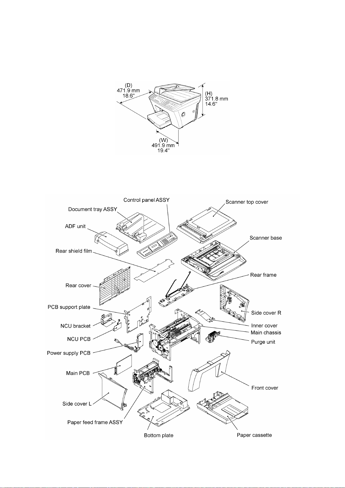
1.1 External Appearance and Weight
The figure below shows the equipment appearance and approximate dimensions.
Weight: Machine proper Approx. 16 kg (36 lb.)
In package Approx. 20 kg (44 lb.)
1.2 Components
The equipment consists of the following major components:
I - 1
Page 7

2. SPECIFICATIONS
MODEL MFC9100C MFC760
GENERAL
Print Engine BY2 BY2
Modem Speed (bps) 14.400 14.400
Transmission Speed (sec) 6 6
ITU-T Group G3 G3
Coding Method MH/MR/MMR MH/MR/MMR
Input/Output Width 8.5"/8.5" 8.5"/8.5"
ADF (pages) 50 50
LCD Size 16 x 2 16 x 2
On-Screen Programming Yes Yes
Backup Clock 1 hour 1 hour
Memory Capacity 8 MB 8 MB
Backup Memory N/A N/A
Optional Memory N/A N/A
Color New Color New Color
Standby Mode N/A N/A
PC-Fax Protocol Compliance Class 1, 2 Class 1,2
Simultaneous Operation Yes (Print/Fax, Print/Copy, Print/Scan) Yes (Print/Fax, Print/Copy, Print/Scan)
Data Modem N/A N/A
Energy Star Compliance Yes Yes
TELEPHONE
Automatic Redial Yes Yes
Handset N/A N/A
One-Touch Dial 16 16
Speed Dial 100 100
Telephone Index Yes Yes
Speaker Phone N/A N/A
Chain Dialing Yes Yes
Caller ID Yes N/A
Call Waiting Caller ID N/A N/A
Distinctive Ringing Yes Yes for UK
Hold/Mute Key N/A N/A
Junk Call Barrier N/A N/A
Power Failure Dialing N/A N/A
Ringer Volume Yes (3 levels + OFF) Yes (3 levels + OFF)
PBX Feature No No
Transfer Method Flash Flash
Digits of One-Touch & Speed Dial 20 digits 20 digits
Registrable Number of Characters 15 chars 15 chars
FAX
Internet FAX Yes (Netcentric) Yes (WordCraft)
Easy Receive/Fax Detect Yes Yes
Fax/Tel Switch N/A N/A
Super Fine Yes Yes
300 dpi Transmission N/A N/A
(1/4)
I - 2
Page 8

MODEL MFC9100C MFC760
Gray Scale 256 256
Contrast Text (Light/Normal/Dark), Photo Text (Light/Normal/Dark), Photo
Smoothing N/A N/A
Call Reservation N/A N/A
Password Check N/A N/A
Enhanced Remote Activation Yes Yes
Multi-Resolution Transmission Yes Yes
Multi Transmission N/A N/A
Next-Fax Reservation Yes (= DUAL ACCESS) Yes (= DUAL ACCESS)
Delayed Timer Yes (Up to 50 timers or 50 jobs) Yes (Up to 50 timers or 50 jobs)
Polling Yes (Std/Seq) Yes (Std/Del/Seq/Sec)
Quick Scan (Memory Transmission) Yes (Super/3 sec.)
Broadcasting Yes (166 locations) Yes (166 locations)
Batch Transmission N/A N/A
Auto Reduction Yes Yes
Out-of-Paper Reception Yes (600 pages x 11K) Yes (600 pages x 11K)
Dual Access Yes Yes
ECM (Error Correction Mode) Yes Yes
ITU SUB Addressing N/A N/A
LIST/REPORT
Activity Report/Journal Report Yes Yes
Transmission Verification Report Yes Yes
Coverpage Yes (Super) Yes (Super)
Help List Yes Yes
Callback Message No No
Caller ID List Yes No
INTERFACE
External TAD Interface Yes Yes
Missing Link/PC Interface No No
Printer Interface Yes (Parallel) Yes (Parallel)
COLOR
BFT Compatible Yes Yes
Color Fax Mode No No
PRINTER
Color/Mono Color Color
Engine Type Piezo inkjet Piezo inkjet
Resolution (dpi) 1440 x 720, 720 x 720,
Speed (ppm) Mono: Up to 7 (360 x 180)
Paper Capacity (sheets) 250 250
- 590 pages x 11K
360 x 360, 360 x 180
Color: Up to 4 (360 x 180)
Yes (Super/3 sec.)
- 590pages x 11K
1440 x 720, 720 x 720,
360 x 360, 360 x 180
Mono: Up to 7 (360 x 180)
Color: Up to 4 (360 x 180)
(2/4)
Optional Paper Capacity (sheets) N/A N/A
Standard Print Language GDI GDI
Emulation Windows GDI, EPSON ESC/P Windows GDI, EPSON ESC/P
Resident Fonts 1 (10, 12, 15 cpi and Ps for each font) 1 (10, 12, 15 cpi and Ps for each font)
Fonts Disk Based 35 35
Paper Handling Size LTR, LGL, A4, B5, A5, A6
CM10, DL, C5, C6, B5
LTR, LGL, A4, B5, A5, A6
CM10, DL, C5, C6, B5
I - 3
Page 9

MODEL MFC9100C MFC760
Paper Cassette Cut sheet: Min.2.75" (W) x 5.0" (L)
Output paper : 100 sheets
Printer Driver Windows 3.1/3.11/95/98/NT4.0
Utility Software Brother Resource Manager Brother Resource Manager
Photo Realistic Print N/A N/A
Ink Cartridge Life (Black) 750 pages (5% duty) 750 pages (5% duty)
Ink Cartridge Life (Color) 400 pages (5% duty for each color) 400 pages (5% duty for each color)
Ink Cartridge Life (Photo) N/A N/A
Interface Type Parallel (IEEE1284) Parallel (IEEE1284)
Bundled Cable Parallel Option
Network Option (Pony) Option (Pony)
COPY
Color Yes Yes
Speed (ppm) Color: 4 ppm, Mono: 5 ppm Color: 4 ppm, Mono: 5 ppm
Multi Copy Yes (Mono: 99 pages/Color: 99 pages) Yes (Mono:99 pages/Color:99 pages)
Sort Yes Yes
Reduction/Enlargement Yes (25% to 400%) Yes (25% to 400%)
Resolution (dpi) Color: Max. 1440 x 720
SCANNER
Color/Mono Color/Mono Color/Mono
Resolution (dpi) 300 x 300 (Opt.)/1200 x 1200 (Int.) 300 x 300 (Opt.)/1200 x 1200 (Int.)
Gray Scale 256 256
TWAIN Compliant Yes Yes
Formats (Import) TIFF, UniDoc, PCX, DCX TIFF, UniDoc, PCX, DCX
Formats (Export) TIFF, UniDoc, PCX, DCX TIFF, UniDoc, PCX, DCX
OCR Yes (Xerox TextBridge) Yes (Xerox TextBridge)
MESSAGE CENTER / MESSAGE MANAGER
ICM Recording Time No No
Page Memory (Out-of-Paper Reception) 600 pages x 11K 600 pages x 11K
OGM (MC/MC Pro/Paging/F/T) No No
TAD Type No No
Memo/Recording Conversation No No
Fax Forwarding Yes Yes
Fax Retrieval Yes Yes
Paging Yes No
Remote Access Yes Yes
Toll Saver No No
MESSAGE CENTER PRO/MESSAGE
MANAGER PRO
Fax & Voice Mail Box No No
Fax- & Voice-on-Demand No No
Max. 8.5" (W) x 14.0" (L)
Envelop (BL/C5/CM10/Mona)
with auto installer program
Min. 360 x 180
Mono: Max. 720 x 720
Min. 360 x 180
Cut sheet: Min.2.75" (W) x 5.0" (L)
Output paper : 100 sheets
Max. 8.5" (W) x 14.0" (L)
Envelop (BL/C5/CM10/Mona)
Windows 3.1/3.11/95/98/NT4.0
Color: Max. 1440 x 720
Min. 360 x 180
Mono: Max. 720 x 720
Min. 360 x 180
(3/4)
I - 4
Page 10

MODEL MFC9100C MFC760
MESSAGE CENTER (PC MC)
Fax Forwarding No No
Paging No No
ICM Recording Time No No
OGM MC/MC Pro/Paging No No
Fax & Voice Mail Box No No
Fax- & Voice-on-Demand No No
VIDEO CAPTURE
Video Capture Yes Yes
Video Print Yes Yes
Video Format NTSC PAL
BUNDLED SOFTWARE
PC Fax SMSI WordCraft
Viewer Visioneer WordCraft
Printer Driver Brother Brother
Others Auto E-mail printing
Netcentric (PC Internet Fax)
3D Fax Speed (PC Color Fax)
Corel Print & Photo House
ACCESSORY
Cartridges Black cartridge
Cyan cartridge
Magenta cartridge
Yellow cartridge
Paper Type BP36CL (720 dpi high-quality coated paper)
BP72CL (720 dpi high-quality coated paper)
BPGLL (Glossy paper)
BPTRL (Transparencies)
BP36CA (360 dpi high-quality coated paper)
BP72CA(720 dpi high-quality coated paper)
Auto E-mail printing
Black cartridge
Cyan cartridge
Magenta cartridge
Yellow cartridge
BPGLA(Glossy paper)
BPTRA(Transparencies)
(4/4)
I - 5
Page 11

CHAPTER II.
INSTALLATION
Page 12

CHAPTER II. INSTALLATION
CONTENTS
1. INSTALLING THE UPDATE DATA TO THE FACSIMILE EQUIPMENT...............II-1
Page 13
1. INSTALLING THE UPDATE DATA TO THE
FACSIMILE EQUIPMENT
If the program version is updated or the main PCB is replaced, install the update program onto the
flash ROM of the main PCB.
The program installation requires a PC/AT-compatible computer (which is capable of running MSDOS or its compatible OS).
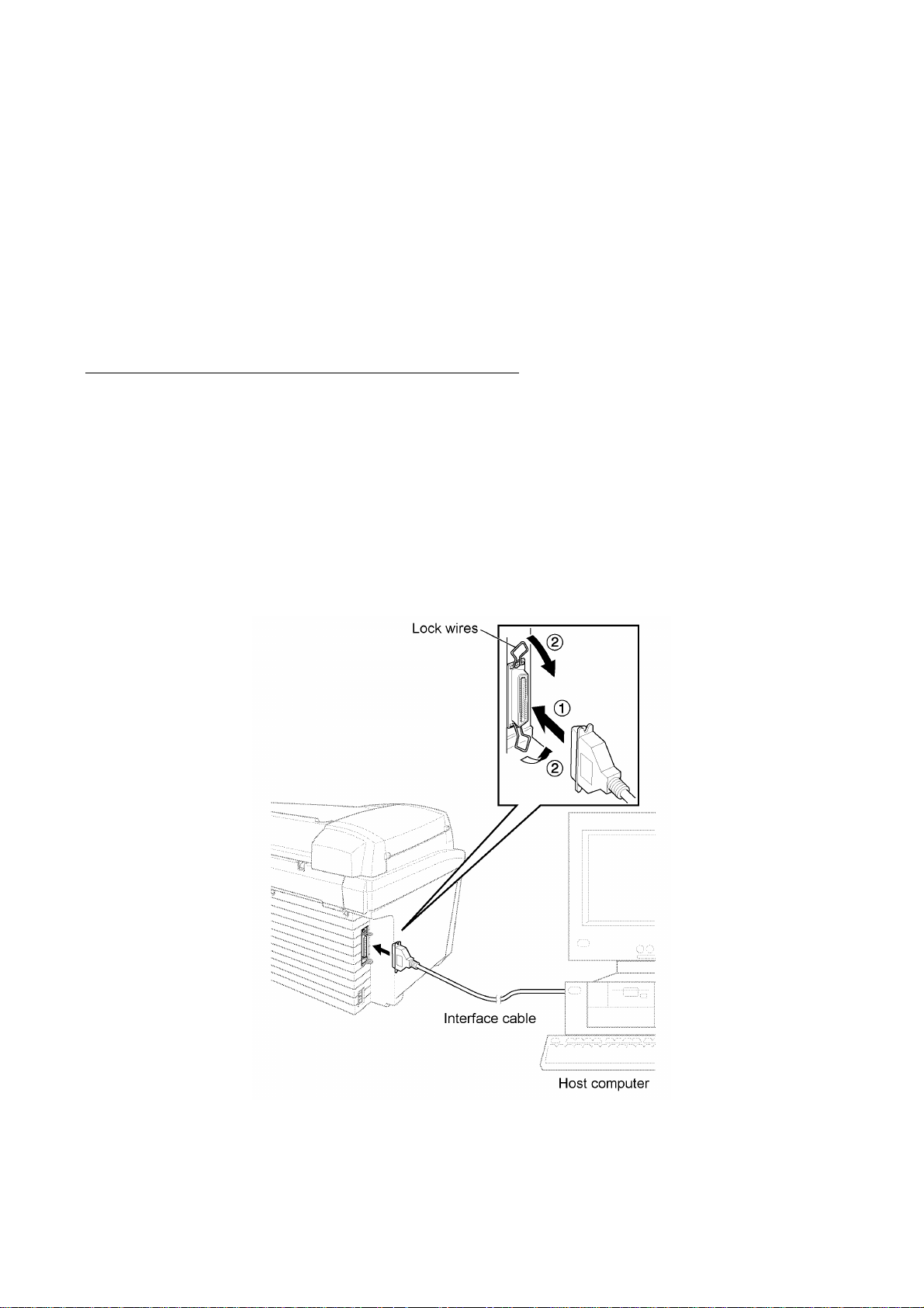
Connecting the facsimile equipment to your computer
(1) Make sure that the equipment's power cord is unplugged from a wall socket.
(2) Make sure that your computer is powered off.
(3) Connect the interface cable to the parallel interface port on the left side of the equipment
and secure it with the lock wires.
(4) Connect the other end of the interface cable to the printer port of your computer and secure
it with the two screws.
(5) Power on your computer.
(6) Plug the equipment's power cord into a wall socket.
II - 1
Page 14

Installing the update data onto the flash ROM of the facsimile equipment
(1) Copy the update data and transfer utility onto the desired directory of the hard disk.
e.g., C:\UPDATE
(2) Click the Start button, point to Programs, and then click MS-DOS Prompt to open an MS-
DOS window.
(3) Type the drive letter where the update data and transfer utility are located. In the above
example, type C: from the command line and press the ENTER key.
Then type CD UPDATE and press the ENTER key.
(4) Check that your computer is connected with the facsimile equipment correctly.
(5) To start the transfer utility transmitting the update data to the flash ROM of the facsimile
equipment, type the following:
ICEN filename /b
Then press the ENTER key.
The equipment beeps and shows the "CONNECTING" on the LCD for one second.
Then, the equipment shows the "DOWNLOADING" on the LCD and starts receiving data
downloaded from the host computer.
During downloading, the equipment beeps intermittently.
Upon completion of the downloading, the equipment beeps continuously.
II - 2
Page 15

CHAPTER III.
THEORY OF OPERATION
Page 16

CHAPTER III. THEORY OF OPERATION
CONTENTS
1. OVERVIEW...........................................................................................................III-1
2. MECHANISMS......................................................................................................III-2
2.1 Scanner Mechanism.....................................................................................III-3
2.2 Ink Jet Printing Mechanism...........................................................................III-5
2.2.1 Paper pick-up, registration, feeding, and ejecting mechanisms..............III-5
2.2.2 Ink jet printing and capping mechanisms...............................................III-6
2.2.3 Purging mechanism..............................................................................III-9
2.2.4 Carriage drive mechanism....................................................................III-11
2.3 Sensors and Actuators..................................................................................III-12
3. CONTROL ELECTRONICS..................................................................................III-15
3.1 Configuration................................................................................................III-15
3.2 Main PCB.....................................................................................................III-16
3.3 NCU PCB.....................................................................................................III-18
3.4 Control Panel PCB........................................................................................III-21
3.5 Power Supply PCB.......................................................................................III-22
Page 17
1. OVERVIEW
III - 1
Page 18
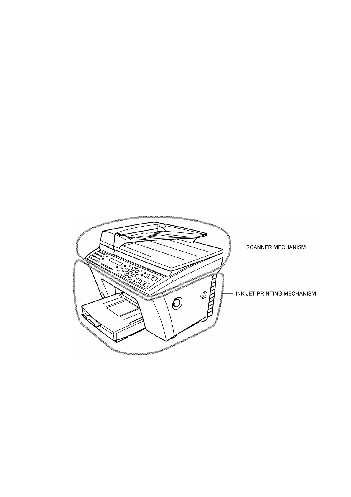
2. MECHANISMS
The equipment is classified into the following mechanisms:
n SCANNER MECHANISM – ADF mechanism
n INK JET PRINTING MECHANISM – Paper pick-up, registration, feeding, and ejecting
n SENSORS AND ACTUATORS
– Document scanning mechanism
mechanisms
– Ink jet printing and head capping mechanisms
– Purging mechanism
– Carriage drive mechanism
III - 2
Page 19
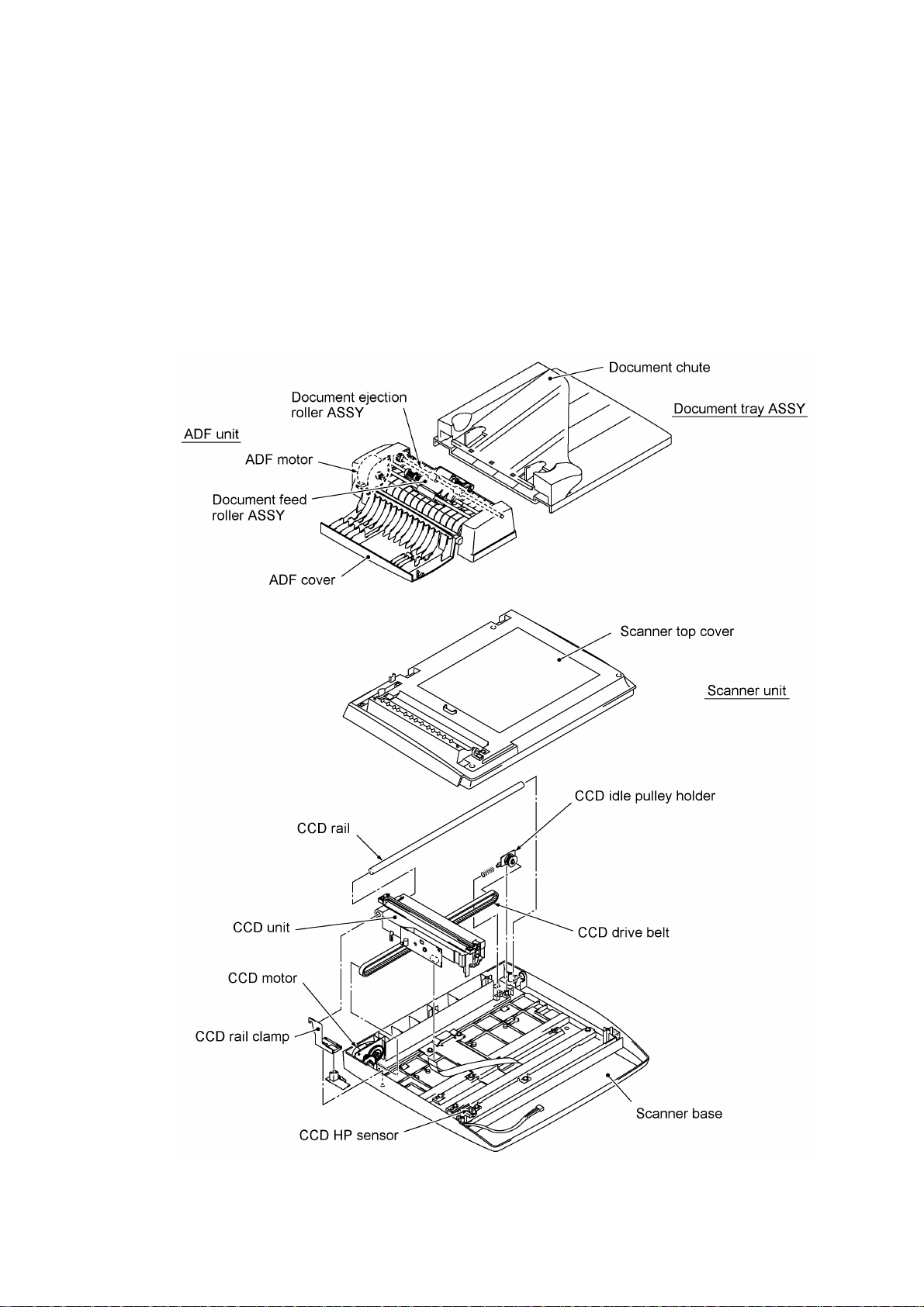
2.1 Scanner Mechanism
This mechanism consists of the following:
- document tray ASSY which consists of a document chute and document tray,
- automatic document feeder (ADF) unit which consists of a document feed roller ASSY,
document ejection roller ASSY, ADF motor, and document front and rear sensors, and
- scanner unit which consists of a scanner top cover, CCD unit, CCD drive mechanism, CCD HP
sensor, and scanner base.
For details about the sensors, refer to Section 2.3.
III - 3
Page 20

This scanner mechanism supports a dual scanning system.
(1) If you set documents with their faces up on the document chute and start the scanning
operation, the ADF motor rotates so that the document feed roller ASSY feeds those
documents into the ADF unit, starting from the bottom sheet to the top, page by page. Each
document curves downwards and turns to the right so as to advance above the CCD unit, and
then it is fed out to the document tray with the document ejection roller ASSY.
This way, documents move above the CCD unit being kept in a stationary position.
(2) If you open the scanner unit, put a sheet of document (or put a bound book opened) on the
glass of the scanner top cover, close the scanner unit, and start the scanning operation, then
the CCD drive mechanism will be driven. That is, the CCD motor rotates and its rotation will
be transmitted via the gear train to the CCD drive belt.
The CCD unit, which is supported and guided by the CCD rail, is secured to the CCD drive
belt. Clockwise and counterclockwise rotations of the CCD motor move the CCD unit to the
right and left, respectively.
In this scanning system, the CCD unit moves horizontally beneath a document being kept in
stationary position.
The CCD unit contains a charge coupled device (CCD) image sensor. The cold-cathode
fluorescent lamp illuminates a document and the reflected light of the scanned image data is
transmitted via the mirrors into the lens which reduces the scanned data so as to form the image
on the CCD.
III - 4
Page 21
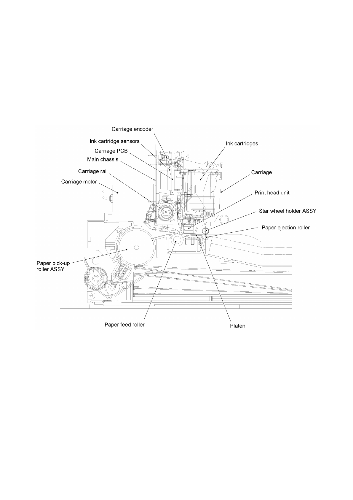
2.2 Ink Jet Printing Mechanism
2.2.1 Paper pick-up, registration, feeding, and ejecting mechanisms
The paper pick-up, registration, feeding, and ejecting mechanisms are driven by a single paper
feed motor.
III - 5
Page 22
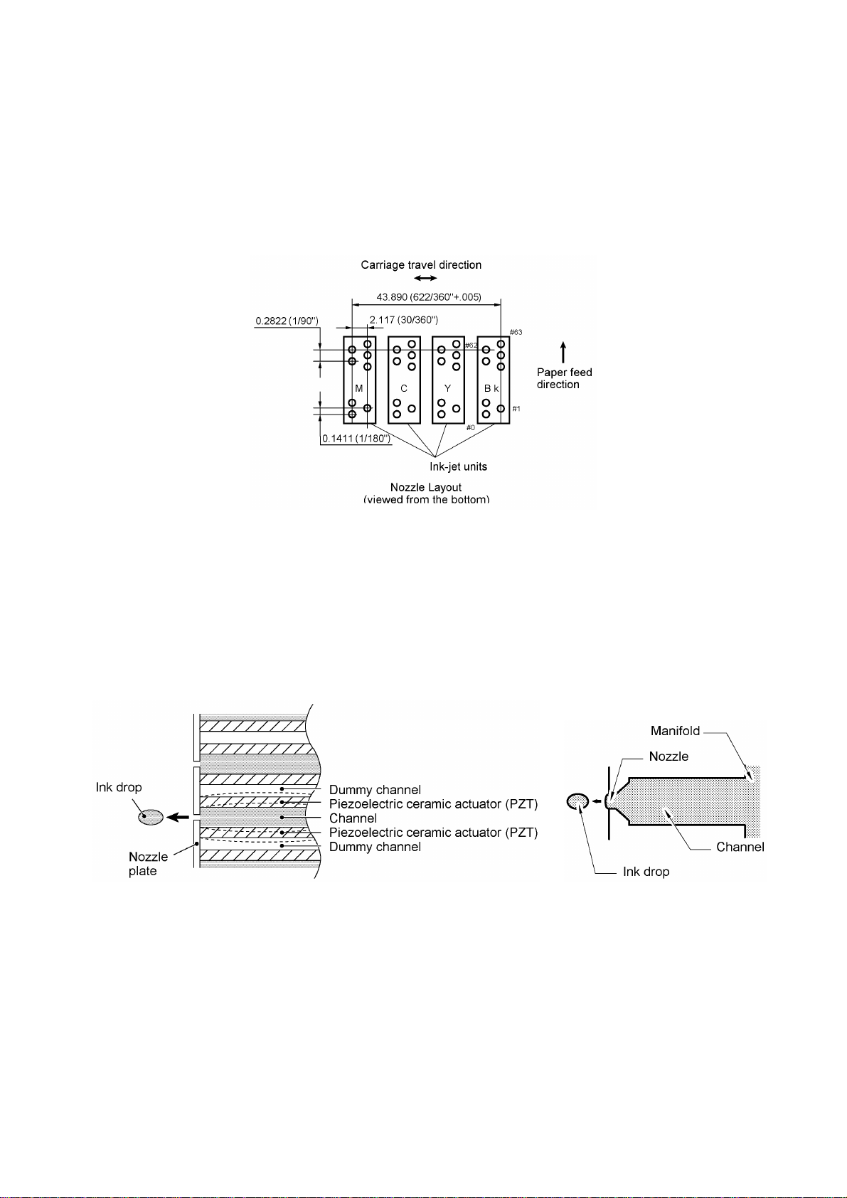
2.2.2 Ink jet printing and capping mechanisms
(1) Print head
This equipment uses drop-on-demand ink jet printing. The print head has four ink-jet units for four
color inks, each of which consists of 64 nozzles, 64 channels sandwiched by a pair of piezoelectric
ceramic actuators (PZT), manifold, and filter.
If a drive voltage* is applied to the electrodes formed on the surface of the piezoelectric actuators,
those actuators will be distorted as shown with broken lines in the illustration given below so that
the ink in the manifold will be vacuumed out to the channel.
(*The controller switches the drive voltage between 28 levels within 13.7V to 29.4V ±3%
depending upon the ambient temperature detected by the head thermistor.)
If deenergized, the piezoelectric actuators return to the previous form so as to apply pressure to
the ink in the channel, causing the ink to jet out through the nozzle. The jetted-out ink drop will be
splashed and produce a dot on paper held by the platen.
As the carriage holding the print head travels at the printing speed, the character generator sends
print command pulses to the circuits driving the piezoelectric actuators embedded in the print
head.
For the head thermistor and the head property EEPROM, refer to Section 2.3.
III - 6
Page 23
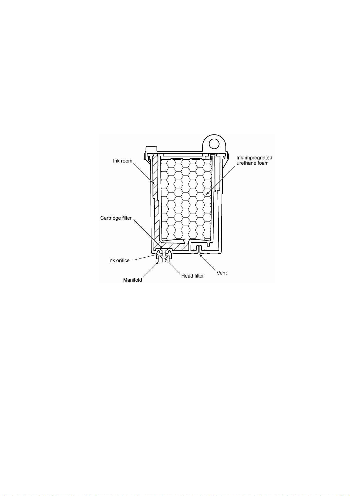
(2) Ink cartridge
The equipment uses four ink cartridges (black, yellow, cyan, and magenta) of disposable type to
supply ink to the print head. As shown below, an ink cartridge contains an ink-impregnated
urethane foam. If ink-jet print operation or purging operation takes place, ink comes out of the
urethane foam and is supplied to the print head through the ink room, filters, and manifold.
For the ink cartridge sensors on the carriage PCB, refer to Section 2.3.
III - 7
Page 24
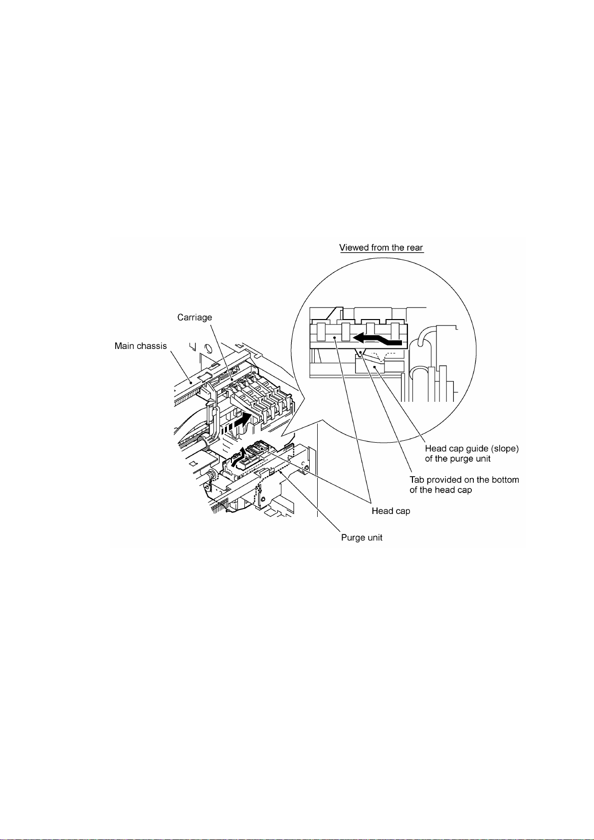
(3) Head cap
Shown below is a head cap which prevents the nozzles of the print head from drying up when they
are not in use.
Upon completion of printing, the carriage travels to the right and moves the head cap provided on
the purge unit together. On the bottom of the head cap is a tab which is lead by the head cap
guide of the purge unit. Accordingly, the rightward movement brings the head cap up to the
position where the head cap comes into tight contact with the print head so as to cap the nozzles.
III - 8
Page 25
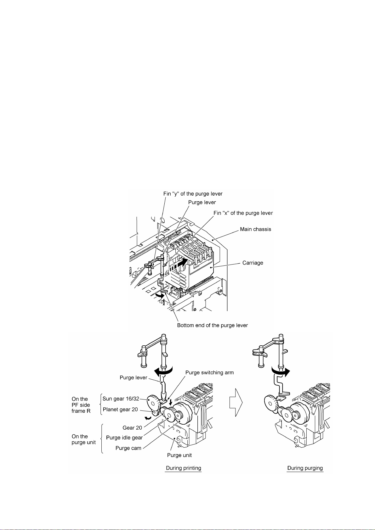
2.2.3 Purging mechanism
The purging mechanism is driven by the paper feed motor located at the left side of the main
chassis. The rotation of the paper feed motor is transmitted to the paper feed roller. At the right
end of the paper feed roller, the rotational torque is further transmitted via the arm 12.3 ASSY
located on the main chassis to the gear train (including the sun gear 16/32 and planet gear 20) on
the PF side frame R.
If the carriage travels from the left to right to reach the purge position, the lower left tab provided
on the back of the carriage turns fin "x" of the purge lever counterclockwise (when viewed from the
top), so the bottom end of the purge lever releases the purge switching arm. Accordingly, the
planet gear 20 will be engaged with the gear 20 and the rotational torque of the paper feed motor
will drive the purge cam.
On the contrary, if the carriage travels from the purge position to the left, the upper right tab on the
back of the carriage turns fin "y" of the purge lever clockwise. The purge lever’s bottom end
pushes down the purge switching arm so that the planet gear 20 will be disengaged from the gear
20. The sun gear 16/32 will simple idle.
That is, when the carriage is in printing operation or the purge cam is in the home position, no
rotation of the paper feed motor is transmitted to the purge gear train; when the carriage is in the
purge position, the motor rotation is transmitted to the purge gear train which rotates the purge
cam.
III - 9
Page 26
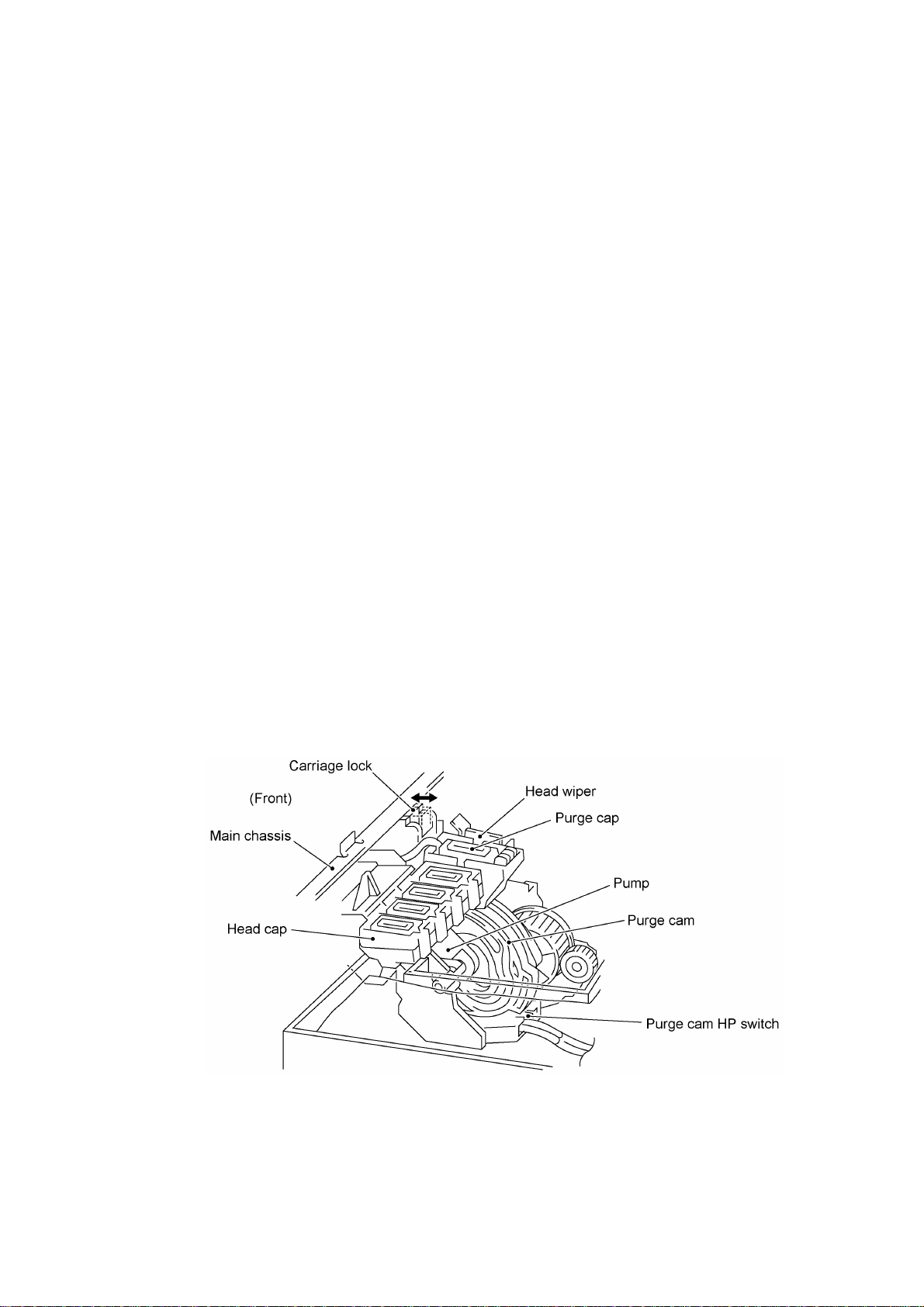
The purge cam is so designed that:
- the carriage lock pops out to lock the carriage before purging and pops in before cleaning with
the wiper,
- the purge cap comes out and becomes pressed against the nozzle ends of an ink-jet unit,
- the pump works to draw out ink from the head nozzles and drains it into the ink absorbers,
and
- the head wiper comes out to clean the nozzle surface.
A sequence of the above operations is carried out by one rotation of the purge cam. The home
position of the purge cam is detected by the HP switch. For the purge cam HP switch, refer to
Section 2.3.
(1) Carriage lock
If the purge cam is driven, the carriage lock of the purge unit pops out and locks the carriage to
align a particular ink-jet unit with the purge cap during purging operation. After purging but before
cleaning with the wiper, it pops in to release the carriage. When the power is off, the carriage lock
keeps the print head pressed against the head cap.
(2) Pressing the purge cap against the nozzle ends
The purge cap comes out and becomes pressed against the nozzle ends of an ink-jet unit.
(3) Purging
If activated, the pump draws out ink from the head nozzles and drains it into the ink absorbers to
remove air bubbles or dust from the inside of the nozzles and channels.
(4) Cleaning with the head wiper
After purging operation, the wiper comes out and the carriage moves from the right to left so as to
clean ink remaining on the head surface.
III - 10
Page 27
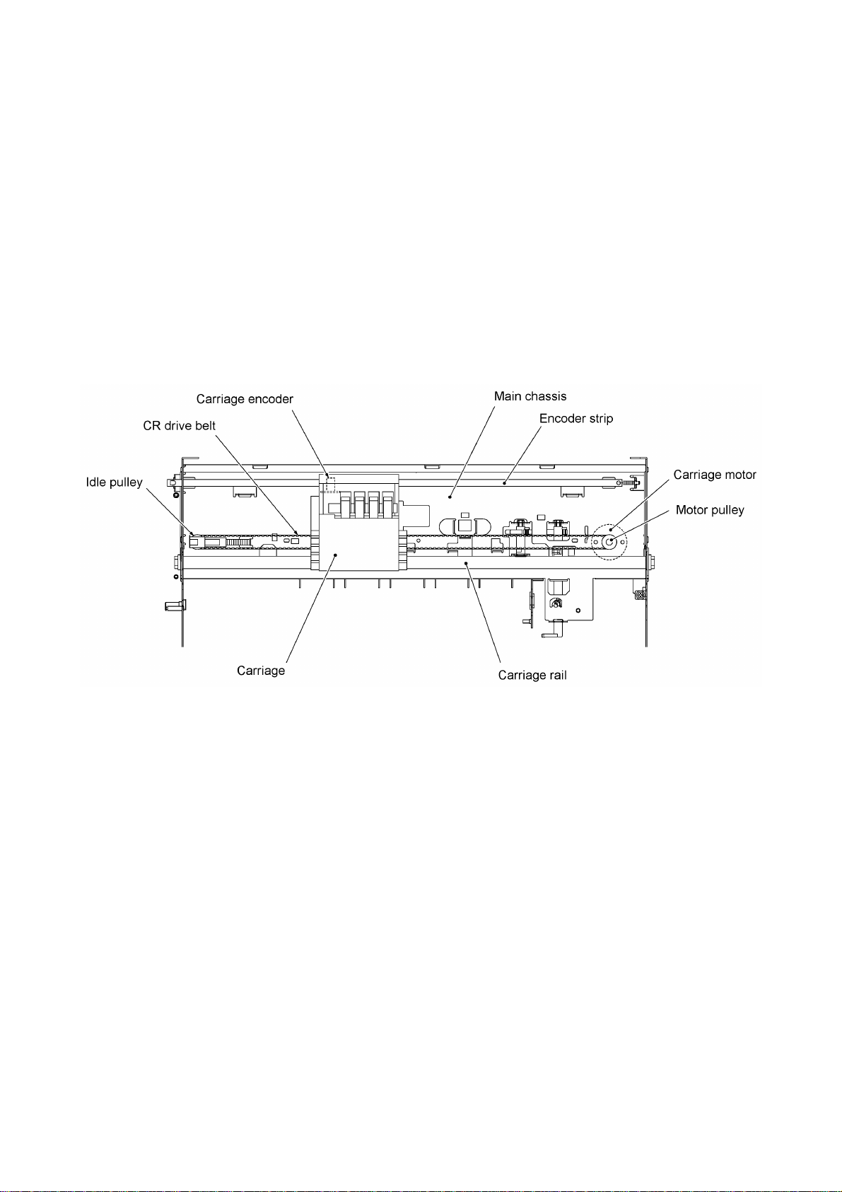
2.2.4 Carriage drive mechanism
The carriage motor controls horizontal motion. The motor rotation is transmitted via the motor
pulley to the CR drive belt.
The carriage, which is supported and guided by the carriage rail, is secured to the CR drive belt.
Clockwise and counterclockwise rotations of the carriage motor move the carriage to the right and
left, respectively.
On the back of the carriage is the carriage encoder which tells the control circuitry the current
carriage position counted based on the carriage home position by using the encoder strip attached
to the main chassis.
III - 11
Page 28

2.3 Sensors and Actuators
This equipment has the following sensors and thermistor.
Sensor name Type Located on
Document front sensor
Document rear sensor
Cover sensor Photosensor Cover sensor PCB on the scanner base
CCD HP sensor Photosensor Scanner base
Registration sensor
Paper width sensor
Paper ejection sensor
Cassette sensor
Ink cartridge sensors Mechanical switches Carriage PCB
Black ink empty sensor Photosensor Carriage PCB
Carriage encoder Photosensor Carriage PCB
Head thermistor Thermistor Carriage PCB
Head property EEPROM Print head unit (Head PCB)
Purge cam HP switch Mechanical switch Purge cam (→Main PCB)
Photosensor Document sensor PCB
Photosensor Paper width/registration sensor PCB on the
upper paper chute
Photosensor Paper ejection/cassette sensor PCB on the
lower paper chute
• Document front sensor which detects the presence of documents.
• Document rear sensor which detects the leading and trailing edges of pages to tell the control
circuitry when the leading edge of a new page has reached the starting position and when the
scan for that page is over.
• Cover sensor which detects whether the scanner unit is closed.
• CCD HP sensor which detects whether the CCD unit is in the home position.
• Registration sensor which detects the leading and trailing edges of paper, which allows the
controller to determine the registration timing.
• Paper width sensor which detects whether the paper width is A4-size or wider.
• Paper ejection sensor which detects whether the paper goes out of the equipment.
• Cassette sensor which detects whether the paper cassette is loaded.
• Ink cartridge sensors, each of which detects whether an ink cartridge is loaded.
• Black ink empty sensor which detects whether the black ink cartridge is empty.
• Carriage encoder which detects the current carriage position and carriage travel speed. If the
carriage travel speed varies abnormally, the controller regards it as a paper jam.
III - 12
Page 29

• Head thermistor which allows the controller to control the temperature of the print head.
According to the change of the thermistor's internal resistance monitored, the control circuitry
regulates the drive voltage applied to the head’s piezoelectric ceramic actuators since the
viscosity of the ink varies depending upon the temperature. If the head thermistor detects
5.5°C or below, or 48°C or higher after two hours of powering-on state, the equipment stops
printing and stores print data into the DRAM.
• Head property EEPROM which stores the head property information. If you set the print head
unit on the carriage, the control circuitry on the main PCB reads the information and regulates
the drive voltage applied to the head’s piezoelectric ceramic actuators.
• Purge cam HP switch which detects whether the purge cam is in the home position.
The above photosensors are a photointerrupter consisting of a light-emitting diode and a lightsensitive transistor. Each of them has an actuator separately arranged as shown on the next
page.
III - 13
Page 30
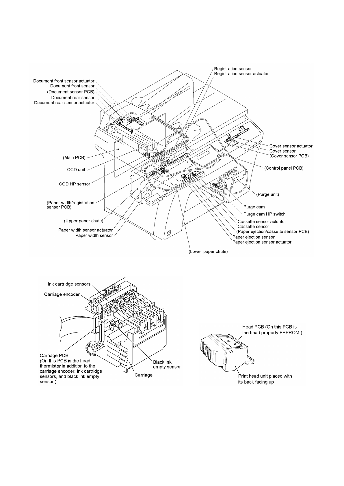
Location of Sensors and Actuators
III - 14
Page 31

3. CONTROL ELECTRONICS
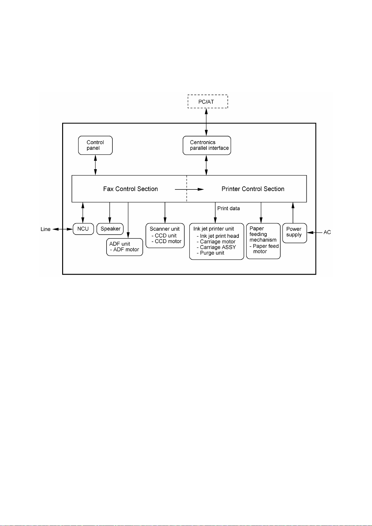
3.1 Configuration
The hardware configuration of the facsimile equipment is shown below.
*1 On the document sensor PCB are these sensors:
Ÿ Document front sensor
Ÿ Document rear sensor
*2 On the cover sensor PCB is a cover sensor.
*3 The CCD HP sensor is located on the scanner base.
*4 On the carriage PCB are these sensors:
Ÿ Head thermistor
Ÿ Ink cartridge sensors
Ÿ Black ink empty sensor
Ÿ Carriage encoder
*5 On the head PCB of the print head unit is a head
property EEPROM.
*6 The purge cam HP switch is located on the purge
unit.
*7 On the paper width/registration sensor PCB are these
sensors:
Ÿ Paper width sensor
Ÿ Registration sensor
*8 On the paper ejection/cassette sensor PCB are these
sensors:
Ÿ Paper ejection sensor
Ÿ Cassette sensor
Configuration of Facsimile Equipment
III - 15
Page 32

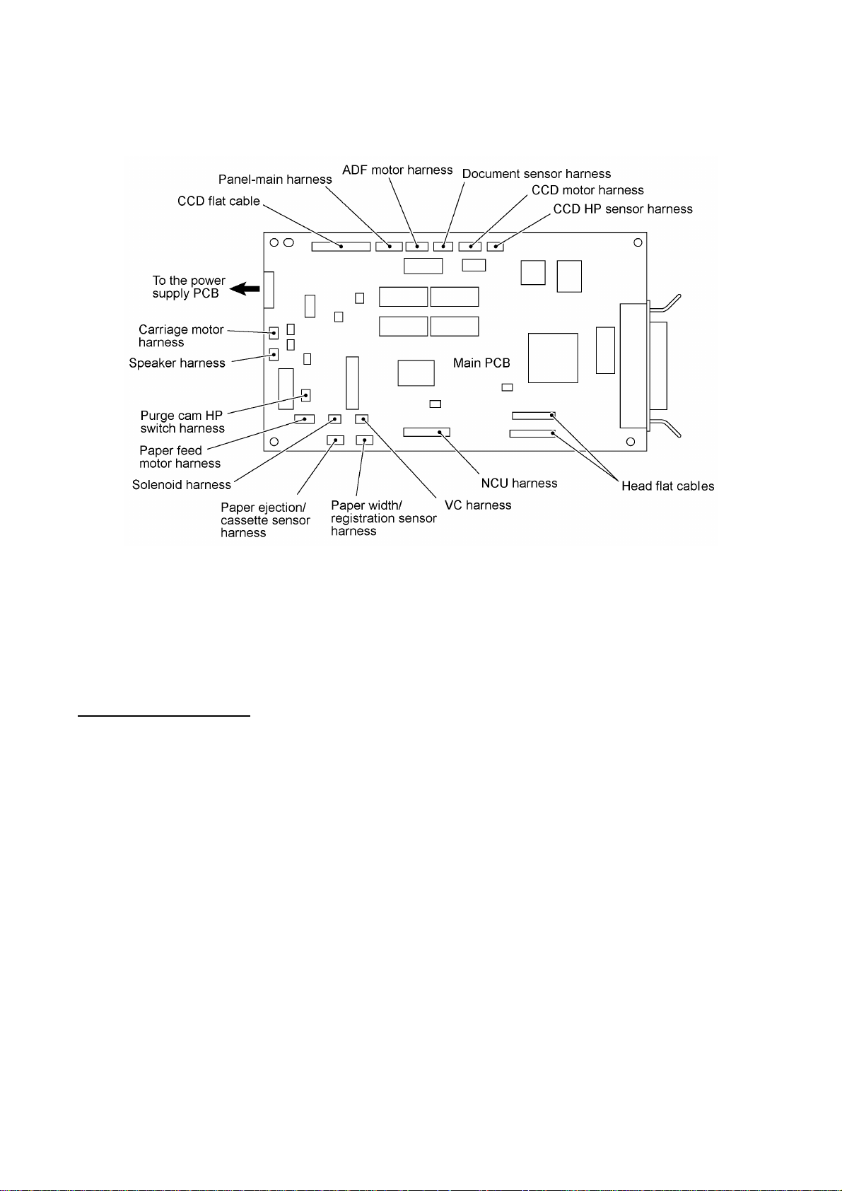
3.2 Main PCB
The main PCB, which is the nucleus controlling the entire operation of the equipment, consists of a
CPU, gate array, memories, MODEM, motor drive circuitry, sensor detection circuitry, and analog
circuits for scanning and printing.
Block Diagram of Main PCB
III - 16
Page 33

III - 17
Page 34

3.3 NCU PCB
The NCU PCB switches the communications line to telephone or built-in MODEM, under the
control of the main PCB.
MFC9100C American version
III - 18
Page 35

MFC9100C Asian/Oceanian versions
III - 19
Page 36

MFC760
III - 20
Page 37

3.4 Control Panel PCB
The control panel PCB and the main PCB communicate with each other by serially transmitting
commands and data.
The control panel unit consists of a gate array, an LCD and LEDs, which are controlled by the gate
array according to commands issued from the control CPU on the main PCB.
The calendar clock is backed up by the backup circuit on the main PCB.
The panel FPC is a flexible keyboard PCB which integrates the key matrix having rubber keytops.
Control Panel PCB and its Related Circuit
III - 21
Page 38
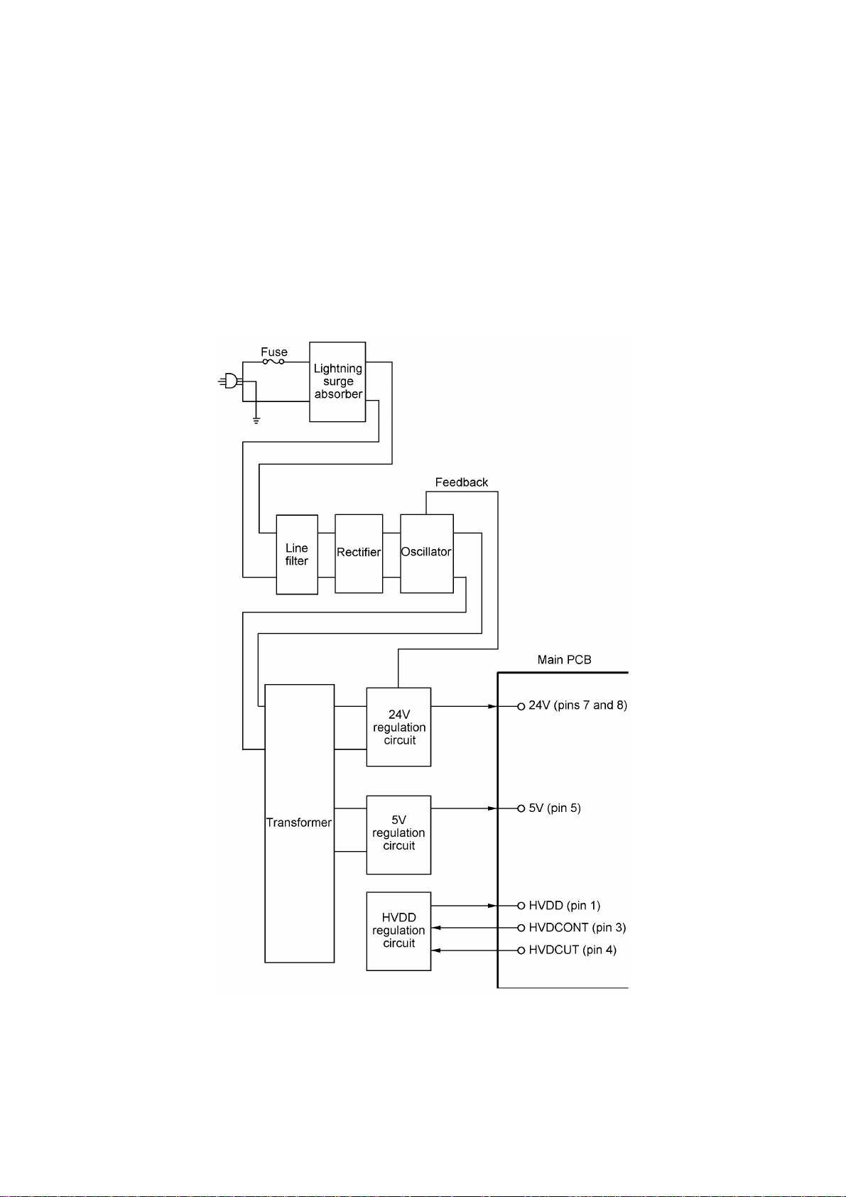
3.5 Power Supply PCB
The power supply uses the switching regulator to generate DC power (+24V, +5V, and HVDD)
from a commercial AC power line.
The +24V source is stabilized and fed to the motors and solenoid for feeding documents and
recording paper, as well as to the LED array of the CIS unit.
The +5V source is stabilized and fed to the logic, etc.
The HVDD is fed to the piezoelectric ceramic actuators embedded in the print head. It varies
within 13.7V to 29.4V depending upon the temperature detected by the head thermister.
Power Supply Circuit
III - 22
Page 39

CHAPTER IV.
DISASSEMBLY/REASSEMBLY,
LUBRICATION AND ADJUSTMENT
Page 40

CHAPTER IV. DISASSEMBLY/REASSEMBLY,
LUBRICATION AND ADJUSTMENT
CONTENTS
1. DISASSEMBLY/REASSEMBLY ..........................................................................IV-1
n Safety Precautions..............................................................................................IV-1
Tightening Torque List........................................................................................IV-2
n Preparation.........................................................................................................IV-4
n How to Access the Object Component ...............................................................IV-4
n Disassembly Order Flow.....................................................................................IV-5
1.1 Ink Cartridges ................................................................................................IV-6
1.2 Print Head Unit ..............................................................................................IV-8
1.3 Paper Cassette ..............................................................................................IV-12
1.4 Document Tray ASSY ...................................................................................IV-13
1.5 Rear Cover ....................................................................................................IV-15
1.6 ADF Unit .......................................................................................................IV-16
1.7 Control Panel ASSY, Cover Sensor PCB, and Cover Sensor Actuator ...........IV-23
1.8 Scanner Unit..................................................................................................IV-25
1.9 Cover Sheet and Rear Frame ........................................................................IV-31
1.10 Inner Cover and Front Cover
1.11 Side Cover L and VC Connector PCB ............................................................IV-33
1.12 Side Cover R and Speaker ............................................................................IV-34
1.13 NCU PCB ......................................................................................................IV-36
1.14 Power Supply PCB ........................................................................................IV-38
1.15 Main PCB ......................................................................................................IV-39
1.16 PCB Support Plate ........................................................................................IV-42
1.17 Purge Unit .....................................................................................................IV-43
1.18 Star Wheel Holder ASSY ...............................................................................IV-45
1.19 Platen and Its Frame .....................................................................................IV-46
1.20 Flushing Foams .............................................................................................IV-47
1.21 Main Chassis .................................................................................................IV-48
1.22 Lower Paper Chute, Flushing Foams Pack, Paper Ejection/
Cassette Sensor PCB, and Sensor Actuators..................................................IV-51
1.23 Paper Pressure Holders..................................................................................IV-53
................................................................................IV-32
1.24 Paper Feed Motor, Paper Feed Gear L, PF Drive Belt, and
Tension Plate ASSY.......................................................................................IV-55
1.25 Arm 12.3 ASSY and Paper Feed Roller .........................................................IV-58
i
Page 41

1.26 Paper Ejection Roller .....................................................................................IV-59
1.27 Encoder Strip ............................................................................................... .IV-60
1.28 Carriage Rail, Carriage ASSY, and Carriage Motor ........................................IV-61
1.29 Ink Absorbers.................................................................................................IV-65
1.30 Drain Tank .....................................................................................................IV-65
1.31 Bottom Plate ................................................................ .................................IV-66
1.32 Paper Pick-up Roller ASSY, Separation Pad, and Solenoid ...........................IV-66
1.33 Disassembly of Paper Feed Frame ASSY .....................................................IV-69
1.34 Paper Width/Registration Sensor PCB ...........................................................IV-70
2. LUBRICATION......................................................................................................IV-72
[ 1 ] ADF unit ........................................................................................................IV-72
[ 2 ] Shafts on the left side of the main chassis .....................................................IV-73
[ 3 ] Main chassis ..................................................................................................IV-73
[ 4 ] Purge unit ......................................................................................................IV-74
[ 5 ] Idle pulley holder ...........................................................................................IV-74
[ 6 ] Paper feed frame ASSY ................................................................................IV-75
3. ADJUSTMENT......................................................................................................IV-76
3.1 Purge Unit Front-to-rear Adjustment ..............................................................IV-76
3.2 Head-platen Gap Adjustment .........................................................................IV-79
ii
Page 42

1. DISASSEMBLY/REASSEMBLY
nn Safety Precautions
To prevent the creation of secondary problems by mishandling, observe the following precautions
during maintenance work.
(1) Unplug the power cord from the power outlet before replacing parts or units. When having
access to the power supply, be sure to unplug the power cord from the power outlet.
(2) Be careful not to lose screws, washers, or other parts removed for parts replacement.
(3) When using soldering irons and other heat-generating tools, take care not to damage the resin
parts such as wires, PCBs, and covers.
(4) Before handling the PCBs, touch a metal portion of the equipment to discharge static
electricity; otherwise, the electronic parts may be damaged due to the electricity charged in
your body.
(5) When transporting PCBs, be sure to wrap them in conductive sheets such as aluminum foil.
(6) Be sure to reinsert self-tapping screws correctly, if removed.
(7) Tighten screws to the torque values listed on the following pages.
(8) When connecting or disconnecting cable connectors, hold the connector bodies not the
cables. If the connector has a lock, always slide the connector lock to unlock it.
(9) Before reassembly, apply the specified lubricant to the specified points. (Refer to Section 2 in
this chapter.)
(10) After repairs, check not only the repaired portion but also that the connectors and other
related portions function properly before operation checks.
(11) Once the print head prints, it will start head locking operation after five seconds from the end
of printing. The head locking operation will take 5 to 10 seconds. NEVER unplug the power
cord before the equipment completes the head locking operation; doing so will make the print
head unusable and require replacement with a new print head.
When you receive the equipment from the user or when you pack it for sending it back to the
user, check the head locking state.
IV - 1
Page 43

Tightening Torque List
Location Screw type Q'ty Tightening torque
N•m (kgf•cm)
Hinges on the document tray ASSY Taptite, cup B M3x10 6 0.59 ±0.10 (6 ±1)
Document tray ASSY Taptite, cup S M3x8 1 0.69 ±0.10 (7 ±1)
Rear cover Taptite, cup S M3x10 3 0.69 ±0.10 (7 ±1)
Harness support Taptite, cup B M3x8 2 0.59 ±0.10 (6 ±1)
Grounding wire Taptite, cup S M3x6 1 0.69 ±0.10 (7 ±1)
ADF supports Taptite, cup B M3x8 2 0.59 ±0.10 (6 ±1)
ADF side covers F and R Taptite, cup S M3x8 2 0.69 ±0.10 (7 ±1)
ADF motor Screw, pan (washer) M3x6DA 2 0.69 ±0.10 (7 ±1)
ADF parts Taptite, pan B M3x6 1 0.39 ±0.10 (4 ±1)
Upper ADF chute Taptite, cup B M3x8 2 0.59 ±0.10 (6 ±1)
ADF motor bracket Taptite, cup S M3x6 3 0.69 ±0.10 (7 ±1)
Cover sensor PCB Taptite, cup B M3x8 1 0.59 ±0.10 (6 ±1)
Control panel PCB Taptite, cup B M2.6x8 2 0.39 ±0.10 (4 ±1)
Key support plate Taptite, cup B M3x6 6 0.59 ±0.10 (6 ±1)
Torsion bar support Taptite, cup S M3x6 2 0.69 ±0.10 (7 ±1)
Hinges on the scanner unit Taptite, bind B M4x12 4 0.98 ±0.10 (10 ±1)
Scanner top cover Taptite, cup B M4x12 4 0.98 ±0.10 (10 ±1)
CCD rail clamp Taptite, cup B M3x8 1 0.59 ±0.10 (6 ±1)
CCD idle pulley holder Taptite, pan B M3x10 2 0.59 ±0.10 (6 ±1)
CCD motor bracket Taptite, cup B M3x8 3 0.59 ±0.10 (6 ±1)
CCD motor Screw, pan (washer) M3x6DA 2 0.69 ±0.10 (7 ±1)
Flat cable clamp Taptite, cup B M3x8 4 0.59 ±0.10 (6 ±1)
Guide plate Taptite, cup B M3x8 4 0.59 ±0.10 (6 ±1)
Cover sheet Taptite, cup S M3x6 1 0.69 ±0.10 (7 ±1)
Rear frame Taptite, cup S M3x6 4 0.69 ±0.10 (7 ±1)
Hinges on the rear frame Taptite, cup S M3x6 4 0.69 ±0.10 (7 ±1)
Inner cover Taptite, cup S M3x10 1 0.69 ±0.10 (7 ±1)
Front cover Taptite, cup S M3x6 2 0.69 ±0.10 (7 ±1)
Side cover L Taptite, cup S M3x6 2 0.69 ±0.10 (7 ±1)
VC connector PCB Taptite, cup B M3x8 1 0.59 ±0.10 (6 ±1)
VC grounding bracket Taptite, cup S M3x6 1 0.69 ±0.10 (7 ±1)
Side cover R Taptite, cup S M3x6 1 0.69 ±0.10 (7 ±1)
Speaker Taptite, cup B M4x10 2 0.78 ±0.10 (8 ±1)
NCU bracket Taptite, cup S M3x6 2 0.69 ±0.10 (7 ±1)
NCU PCB Taptite, cup S M3x6 1 0.59 ±0.10 (6 ±1)
Power supply PCB Taptite, cup S M3x6 4 0.59 ±0.10 (6 ±1)
AC cord grounding wire Screw, pan (washer) M4x8DB 1 0.59 ±0.10 (6 ±1)
Interface connector Machine screw, pan M3x6 2 0.59 ±0.10 (6 ±1)
IV - 2
Page 44

Location Screw type Q'ty Tightening torque
N•m (kgf•cm)
Main PCB Taptite, cup S M3x6 4 0.59 ±0.10 (6 ±1)
PCB support plate Taptite, cup S M3x6 2 0.69 ±0.10 (7 ±1)
Purge unit Screw, pan (washer) M3x6DB 2 0.69 ±0.10 (7 ±1)
Platen frame Taptite, cup S M3x6 1 0.69 ±0.10 (7 ±1)
Cable clip Taptite, cup S M3x6 1 0.59 ±0.10 (6 ±1)
Main chassis Taptite, cup S M3x6 8 0.69 ±0.10 (7 ±1)
Lower paper chute Taptite, cup B M4x10 2 0.98 ±0.10 (10 ±1)
Tension plate ASSY Screw, pan (washer) M3x8DB 1 0.69 ±0.10 (7 ±1)
Paper feed motor Screw, pan (washer) M3x8DB 2 0.69 ±0.10 (7 ±1)
Paper ejection roller Screw, pan (washer) M2.6x8DB 1 0.29 ±0.10 (3 ±1)
Idle pulley stopper Screw, pan (washer) M3x8DB 1 0.69 ±0.10 (7 ±1)
Eccentric bushings L and R Screw, pan (washer) M3x8DB 2 0.69 ±0.10 (7 ±1)
Carriage motor Screw, pan (washer) M3x6DB 2 0.69 ±0.10 (7 ±1)
Drain tank Taptite, cup S M3x6 1 0.69 ±0.10 (7 ±1)
Bottom plate Taptite, cup S M3x6 4 0.69 ±0.10 (7 ±1)
PF side frame L Taptite, cup S M3x6 2 0.69 ±0.10 (7 ±1)
PF side frame R Taptite, cup S M3x6 2 0.69 ±0.10 (7 ±1)
Taptite, cup B M3x10 2 0.59 ±0.10 (6 ±1)
Paper width/registration sensor PCB Taptite, cup B M2.6x8 1 0.39 ±0.10 (4 ±1)
IV - 3
Page 45

nn Preparation
Prior to proceeding to the disassembly procedure,
(1) Unplug
- the modular jack of the telephone line,
- the PC interface cable, and
- the modular jack of an external telephone set if connected. (Not shown below.)
(2) Remove
- the paper cassette (by lifting up its front end slightly and pulling it out).
NOTE: Do not remove the ink cartridges when disassembling the equipment except when
removing the print head.
nn How to Access the Object Component
• On the next page is a disassembly order flow which helps you access the object components.
To remove the paper feed motor, for example, first find it on the flow and learn its number (
in this case). You need to remove parts numbered , , , , , and so as to
access the paper feed motor.
• Unless otherwise specified, the disassembled parts or components should be reassembled in
the reverse order of removal.
IV - 4
Page 46

nn Disassembly Order Flow
IV - 5
Page 47

1.1 Ink Cartridges
During disassembly jobs (except when removing the print head), all of the four ink cartridges
should be kept in place. The following ink cartridge replacement procedure should apply only
when you replace ink cartridges. When replacing the print head, do not apply this procedure
but the procedure given in Section 1.2.
(1) Plug the power cord into a wall socket.
(2) If any ink empty message (INK EMPTY BLACK, CYAN, MAGENT, or YELLOW) and "PLS
OPEN COVER" are displayed alternately on the LCD, press the open button to open the
scanner unit in order to place the equipment in the ink cartridge replacement mode.
If any ink near-empty message (NEAR EMPTY BLACK, CYAN, MAGENT, or YELLOW) or no
message is displayed on the LCD, follow the steps below in order to place the equipment in
the ink cartridge replacement mode.
1) Press the Ink Management key.
2) Press the 2 key.
3) Press the open button to open the scanner unit.
The carriage automatically moves left to the ink cartridge replacement position.
(3) Pull up the cartridge holder of the ink cartridge to be replaced by pinching its clip with your
fingers.
IV - 6
Page 48

(4) Take out the ink cartridge from the print head.
NOTE: When handling ink cartridges, do not touch their orifices which may stain your hands
or clothing with ink.
(5) Load a new or removed ink cartridge. Be sure to snap it into place.
NOTE: When using a new cartridge, first open the cartridge bag, take out the cartridge, and
remove the sealing tape gently.
(6) Close the cartridge holder until it clicks into place.
(7) Close the scanner unit.
For each of the ink cartridges loaded, the confirmation message will appear as shown below,
asking you whether the ink dot counter should be reset to zero.
DID YOU CHANGE
CYAN? 1.YES 2.NO
In this area appears CYAN, BLCK, YELW, or MGTA.
If you have loaded a new ink cartridge in step (5), press the 1 key to reset the ink dot counter;
if you have reloaded the removed one, press the 2 key.
NOTE: Pressing the 1 key although you have reloaded the removed one could cause inkless
printing.
(8) The equipment automatically enters the purge mode. Select the related ink-jet unit(s) of the
print head for purging air bubbles .
IV - 7
Page 49

1.2 Print Head Unit
During disassembly jobs (except when removing the purge unit, carriage rail or carriage
ASSY), the print head and all the four ink cartridges should be kept in place.
(1) Plug the power cord into a wall socket.
(2) Open the scanner unit and then press the Ink Management key.
(3) Press the 3 key.
REMOVE ALL INKS
AND PRINT HEAD
The carriage automatically moves to the head replacement position (to the left from the home
position).
(4) Pull up all cartridge holders by pinching their clips with your fingers.
IV - 8
Page 50

(5) Remove all ink cartridges, one at a time.
NOTE: When handling ink cartridges, do not touch their nozzles which may stain your hands
or clothing with ink.
(6) Pull the tabs of the print head unit to the front in order to release the rear edge of the print
head unit from the lock provided on the carriage. Then lift the print head unit up and out of
the carriage.
INSTALL HEAD
AND CARTRIDGES
NOTE: Do not touch the printing ends (nozzles) of the print head; doing so will stain your
hands with ink.
NOTE: Be sure to put a head nozzle seal and filter seal on the print head as shown on the
next page. Leaving the print head without those seals will dry up its printing ends and filters,
resulting in a damaged head.
NOTE: Do not touch the control board provided on the rear side of the print head.
IV - 9
Page 51

(7) If the head cap has collected ink, clean it with a head cleaner. If the surrounding parts are
CYAN? 1.YES 2.NO
stained with ink, wipe them off with a clean cloth.
(8) To install a new (or removed) print head unit, take off the yellow head nozzle seal and then
put the print head unit onto the carriage, taking care not to touch the control board provided
on the rear side of the print head.
(9) Push the tabs of the print head unit to the rear until it locks into place.
(10) Remove the yellow head filter seal from the print head unit, then load ink cartridges in the
order of black, yellow, cyan, and magenta. Be sure to snap them into place.
(11) Close the cartridge holders until they click into place.
(12) Close the scanner unit.
For each of the ink cartridges loaded, the confirmation message will appear as shown below,
asking you whether you loaded a new cartridge.
DID YOU CHANGE
(13) If you have loaded a new cartridge, press the 1 key within one minute. The ink dot counter
will be reset to zero.
If you have reloaded the removed one, press the 2 key within one minute.
IV - 10
Page 52

(14) The equipment automatically carries out purging operation for each ink-jet unit of the print
CLEANING CYAN
CLEANING CYAN
1.YES 2.NO
PRESS START KEY
SET PAPER AND
PRESS START KEY
SET PAPER AND
head.
PLEASE WAIT
(Steps (15) through (18) given below will be skipped if you have reinstalled the removed print head
unit.)
(15) Upon completion of purging operation, the following messages appear alternately:
TEST PRINT
Make sure that paper is loaded in the paper cassette and it is set in place, then press the
Start key.
The equipment prints "Nozzle check pattern sheet" and then shows the following message:
TEST PRINT
PRINT OK?
(16) Check the print quality, following the instructions given on "Nozzle check pattern sheet."
If the print quality is OK, press the 1 key and proceed to step (17).
If any of the horizontal lines are missing or no-print areas are found between color blocks,
press the 2 key within one minute, and go back to step (14).
Pressing neither key within one minute makes the equipment proceed to step (17).
(17) The following messages appear alternately:
VERTICAL ALIGN
Make sure that paper is loaded in the paper cassette, then press the Start key within one
minute. The equipment prints "Vertical alignment check pattern sheet."
If the Start key is not pressed within one minute, the equipment automatically returns to the
initial stage of the maintenance mode.
VERTICAL ALIGN
(18) According to the instructions given on "Vertical alignment check pattern sheet," adjust the
alignment of vertical print lines.
IV - 11
Page 53

1.3 Paper Cassette
You may remove the parts from the paper cassette as follows:
(1) Remove the cassette cover.
(2) To remove the front paper guide, lightly press the lock in the direction of arrow • and pull out
the cassette end in the direction of arrow ‚ until it stops.
Turn the paper cassette upside down.
Then pull the hooks of the guide stopper outwards and release the guide stopper from the
pawls of the front paper guide.
(3) To remove the side paper guide, pull the hooks of the guide stopper outwards and release the
guide stopper from the pawls of the side paper guide.
IV - 12
Page 54

1.4 Document Tray ASSY
(1) Fully open the document tray ASSY.
(2) Lift up the document tray ASSY straight and take the hinges out of the scanner unit.
(3) Remove the three screws from each of the hinges.
IV - 13
Page 55

(4) Remove the screw, then lightly tap the left end of the document chute to release the three
hooks from the document tray.
(5) Remove the sponge.
IV - 14
Page 56

1.5 Rear Cover
(1) Remove the three screws and unhook the five pawls from the bottom plate.
(2) Remove the AC cord bushing from the rear cover.
IV - 15
Page 57

1.6 ADF Unit
(1) Remove screw "a" from the harness support.
(2) Remove screw "b" to release the grounding wire.
(3) Disconnect the ADF motor harness and document sensor harness from the main PCB.
IV - 16
"a": Taptite, cup B M3x8
"b": Taptite, cup S M3x6
Page 58

(4) Open the ADF unit (in the direction of arrow •), remove the plastic retaining ring, and release
the arm (arrow ‚) from the boss provided on the scanner top cover.
(5) Open the ADF cover (arrow ƒ) and remove two screws "c."
(6) Lift up the ADF unit. The ADF supports also come off.
(7) Remove screw "d" from the harness support.
IV - 17
"c" and "d": Taptite, cup B M3x8
Page 59

nn Disassembling the ADF unit
1) Open the ADF cover. Pull the ADF side cover outwards and release the ADF cover from the
bosses provided on the ADF side covers.
2) At each of the ADF side covers F and R, remove the screw, pull the unscrewed corner
outwards to release it from the document ejection chute, and unhook the latch.
3) Remove the document ejection chute (which has been secured with the screws removed in
step 2) above).
IV - 18
Page 60

4) At the front end of the document feed roller shaft, remove the pawled bushing by pulling its
pawls outwards. At the rear end, pull the bushing outwards and lift up the document feed
roller ASSY.
5) At the front end of the upper LF roller (gray) shaft, remove the pawled bushing by pulling its
pawls outwards. At the rear end, pull the bushing outwards and lift up the upper LF roller
ASSY.
6) Remove the two screws and take off the ADF motor.
If you do not need to remove the ADF parts, skip to step 10).
7) Peel off the ADF film.
NOTE: Once removed, the ADF film will become unusable and a new part will have to be put
back in.
8) Remove the screw and take off the spring plate A, separation rubber, rubber holder, and
compression spring.
9) Push the hooks provided on the upper ADF chute and remove the pressure rollers and their
springs.
IV - 19
Page 61

10) Remove the two screws and lift up the upper ADF chute.
11) Turn the document front sensor actuator as shown below and lift it up.
12) Turn the document rear sensor actuator as shown below and lift it up.
13) Disconnect the document sensor harness from the document sensor PCB and take out its
harness from the harness guides.
14) Unhook the two latches (large and small latches in this order) from the document sensor PCB
and lift it up.
IV - 20
Page 62

15) At the front end of the document ejection roller shaft, remove the pawled bushing by pulling its
pawls outwards. At the rear end, pull the bushing outwards and lift up the document ejection
roller ASSY.
16) Remove the three screws and take off the motor bracket.
17) At the front end of the lower LF roller (black) shaft, remove the pawled bushing by pulling its
pawls outwards. At the rear end, pull the bushing outwards and remove the lower LF roller
ASSY.
18) Turn the lower ADF chute upside down.
19) Pull the arm outwards and take it off.
20) At the rear side of the lower ADF chute, remove the gear 19/36 by pulling its pawl outwards.
21) Remove the gear 64 by pulling its pawl outwards.
22) Unhook the two springs.
23) Pull out the white roller bushing F by pulling its pawls outwards.
24) Remove the white roller together with the white roller bushing R and gear 27.
IV - 21
Page 63

nn Reassembling Notes
• Take care not to mistake the upper LF roller ASSY (gray) for the lower LF roller ASSY (black).
• When setting the document sensor PCB back into place, do not push it down straight, but first
fit the PCB in the large latch and then fit it in the small latch (see the illustration given on page
IV-20).
• Be sure to route the document sensor harness through the three harness guides so that it will
not interfere with the document rear sensor actuator. (See the illustration given on page IV-20.)
• Reinstall the ADF motor with its connector side facing up. (See the illustration given on page
IV-19.)
• Reinstall the ADF side covers so that the tabs of the ADF side plates become fitted inside the
ribs provided on the ADF side covers. (See the illustration given on page IV-18.)
• When reinstalling the ADF side cover R, be sure to route the document sensor harness, ADF
motor harness, and grounding wire between the boss and the ADF side cover R. (See the
illustration given on page IV-18.)
• When reinstalling the ADF unit, first set the ADF support onto rear pin "x" of the ADF unit, set
the ADF unit back into place, set the other ADF support onto front pin "y," then secure those
ADF supports with two screws "c." (See the illustration given on page IV-17.)
IV - 22
Page 64

1.7 Control Panel ASSY, Cover Sensor PCB, and Cover Sensor Actuator
(1) Push the open button to open the scanner unit.
(2) Insert the tip of a flat screwdriver into each of the four holes provided in the bottom of the
scanner unit and unhook the four latches while lifting up the control panel ASSY.
(3) Slightly slide the control panel ASSY towards you to separate it from the scanner unit.
(4) Disconnect the cover sensor harness and panel-main harness from the control panel PCB.
(5) Turn the cover sensor actuator as shown below and lift it up.
(6) Remove the screw and take off the cover sensor PCB.
IV - 23
Page 65

nn Disassembling the Control Panel ASSY
1) Turn the control panel ASSY upside down.
2) Remove two screws "a."
3) Slightly lift up the control panel PCB, then unlock the FPC key connector and disconnect the
FPC key. Next, unlock the LCD cable connector and disconnect the LCD flat cable.
4) Remove six screws "b."
5) Remove the key support plate and FPC key.
"a": Taptite, cup B M2.6x8
"b": Taptite, cup B M3x6
6) As shown below, slightly pull the clamp outwards and take out the LCD while pulling the LCD
flat cable gently.
NOTE: Do not take out the LCD except when the LCD is defective and requires replacement.
nn Reassembling Notes
• Before reinstalling the LCD to the control panel, wipe fingerprints or dust off the LCD surface
and control panel window with a soft cloth.
• A new LCD is covered with a protection sheet. Before installing it, remove the protection sheet.
IV - 24
Page 66

1.8 Scanner Unit
(1) Disconnect the following flat cable and harnesses from the main PCB:
- CCD flat cable
- Panel-main harness
- CCD motor harness
- Scanner HP sensor harness
(2) Press the pawl of the link, move the link to the right, and release it from the shaft of the link
support secured to the bottom of the scanner unit.
NOTE: Be careful with the scanner unit that will spring open further.
(3) Remove the two screws from the torsion bar support and take it off from the rear frame.
(4) Pull out the top ends of the torsion bars from the opening provided in the torsion bar plate.
(5) Keep the scanner unit at a right angle to the machine body, and pull out the pivot pins
inwards. The scanner unit may be separated.
IV - 25
Page 67

nn Disassembling the Scanner Unit
The disassembling job of the scanner unit should be done in a clean room to prevent dust or dirt
from getting into the scanner unit.
1) Remove the four screws from the scanner top cover.
2) Separate the scanner top cover from the scanner base.
3) Turn the gear 17/97 to move the CCD unit to the right to make the following job easier.
4) Remove screw "a" and take out the CCD rail clamp. (See the illustration given on the next
page.)
5) Remove two screws "b" from the CCD idle pulley holder, then remove the CCD drive belt
from the idle pulley.
6) Lift up the CCD rail together with the CCD unit and CCD drive belt, and then disconnect the
CCD flat cable.
NOTE: When handling the CCD unit, do not touch the CCD PCB or glasses but hold the
hatched sections as shown below.
IV - 26
Page 68

7) Pull out the CCD rail from the CCD unit.
8) Remove the CCD lock.
IV - 27
"a": Taptite, cup B M3x8
"b": Taptite, pan B M3x10
Page 69

9) Pull up the CCD motor harness and disconnect it from the CCD motor.
10) Remove three screws "c" from the motor bracket.
11) Lift up the motor bracket.
12) Remove two screws "d" from the CCD motor.
13) Disconnect the CCD HP sensor harness from the sensor.
14) Remove the CCD HP sensor.
"c": Taptite, cup B M3x8
"d": Screw, pan (washer) M3x6DA
IV - 28
Page 70
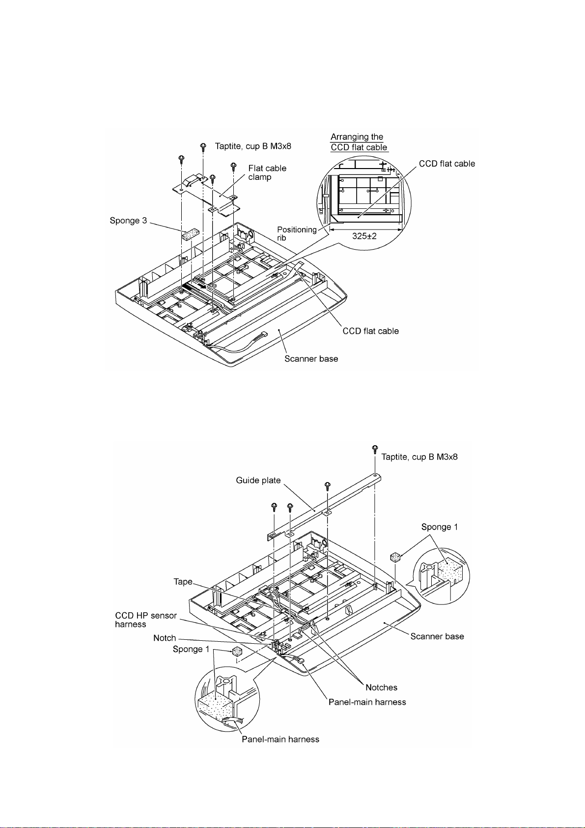
15) Remove the four screws and take off the flat cable clamp. Remove sponge 3 attached with
adhesive tape.
16) Remove the CCD flat cable (which is attached with adhesive tape).
17) Remove the four screws and take off the guide plate.
18) Remove tape and sponges 1, then take out the panel-main harness and CCD HP sensor
harness.
NOTE: Once removed, the sponges 1 will become unusable and new ones will have to be put
back in.
IV - 29
Page 71

nn Reassembling Notes
• Route the panel-main harness and CCD HP sensor harness through the three notches, then
tape them as illustrated on the previous page.
• When replacing the CCD flat cable with a new one, be sure to arrange the new cable as
illustrated below, then route it along the positioning rib as shown on the previous page.
• Set the CCD motor back into place with its connector side facing up as shown on page IV-28.
• Set the CCD lock in the release (forward) position. If the CCD lock is placed in the lock
position, the CCD home positioning will fail in the next powering-up sequence. If this happens,
turn the CCD lock to the release position.
IV - 30
Page 72

1.9 Cover Sheet and Rear Frame
(1) Remove screw "a" and take off the cover sheet.
(2) Remove four screws "b" and take off the rear frame.
nn Reassembling Notes
• When setting the rear frame back into place, fit its pawls over the top edge of the PCB support
plate as shown above.
• When setting the cover sheet back into place, fit its tabs into the cutouts provided in the rear
frame as shown above.
"a" and "b": Taptite, cup S M3x6
IV - 31
Page 73

1.10 Inner Cover and Front Cover
(1) If the scanner unit has not been removed, push the open button to open the scanner unit.
(2) Remove screw "a" from the inner cover.
(3) Unhook latch "x" and shift the inner cover to the left and up.
(4) Remove two screws "b."
(5) Slightly pull up three tabs to release them from bosses and then remove the front cover to the
front.
IV - 32
"a": Taptite, cup S M3x10
"b": Taptite, cup S M3x6
Page 74

1.11 Side Cover L and VC Connector PCB
(1) Remove three screws.
(2) Disconnect the VC harness from the VC connector PCB.
(3) Unhook the two latches from the main chassis and remove the side cover L together with the
VC connector PCB.
(4) Remove the screw and take off the VC connector PCB and VC grounding bracket.
IV - 33
Page 75

1.12 Side Cover R and Speaker
(1) Open the cable clamp (see the illustration given on page IV-36) and release the harnesses.
(2) Disconnect the speaker harness from the main PCB. (See the illustration given on the next
page.)
(3) Remove the screw from the top of the side cover R.
(4) Unhook the two latches from the main chassis and remove the side cover R together with the
speaker.
IV - 34
Page 76

(5) Remove the two screws and take out the speaker.
IV - 35
Page 77

1.13 NCU PCB
(1) Disconnect the head flat cables from the main PCB.
(2) Pull the flat core of the head flat cables up and off the core support.
(3) Disconnect the NCU harness from the main PCB.
(4) Open the cable clamp and release the harnesses.
(5) Remove the two screws (three screws if the side cover L has not been removed).
(6) Slide the NCU bracket to the left (when viewed from the rear) and to the rear.
IV - 36
Page 78

(7) Remove the screw.
(8) Take out the NCU PCB in the direction of arrows • and ‚.
nn Reassembling Notes
• When setting the NCU PCB back into its bracket, fit its edges onto "a" and into "b" as shown
above.
IV - 37
Page 79

1.14 Power Supply PCB
(1) Remove the four screws from the power supply PCB.
(2) Remove the screw from the grounding wire.
(3) Slide the power supply PCB to the left (when viewed from the rear) to disconnect it from the
main PCB, then take it out together with the PS insulator film.
IV - 38
Page 80
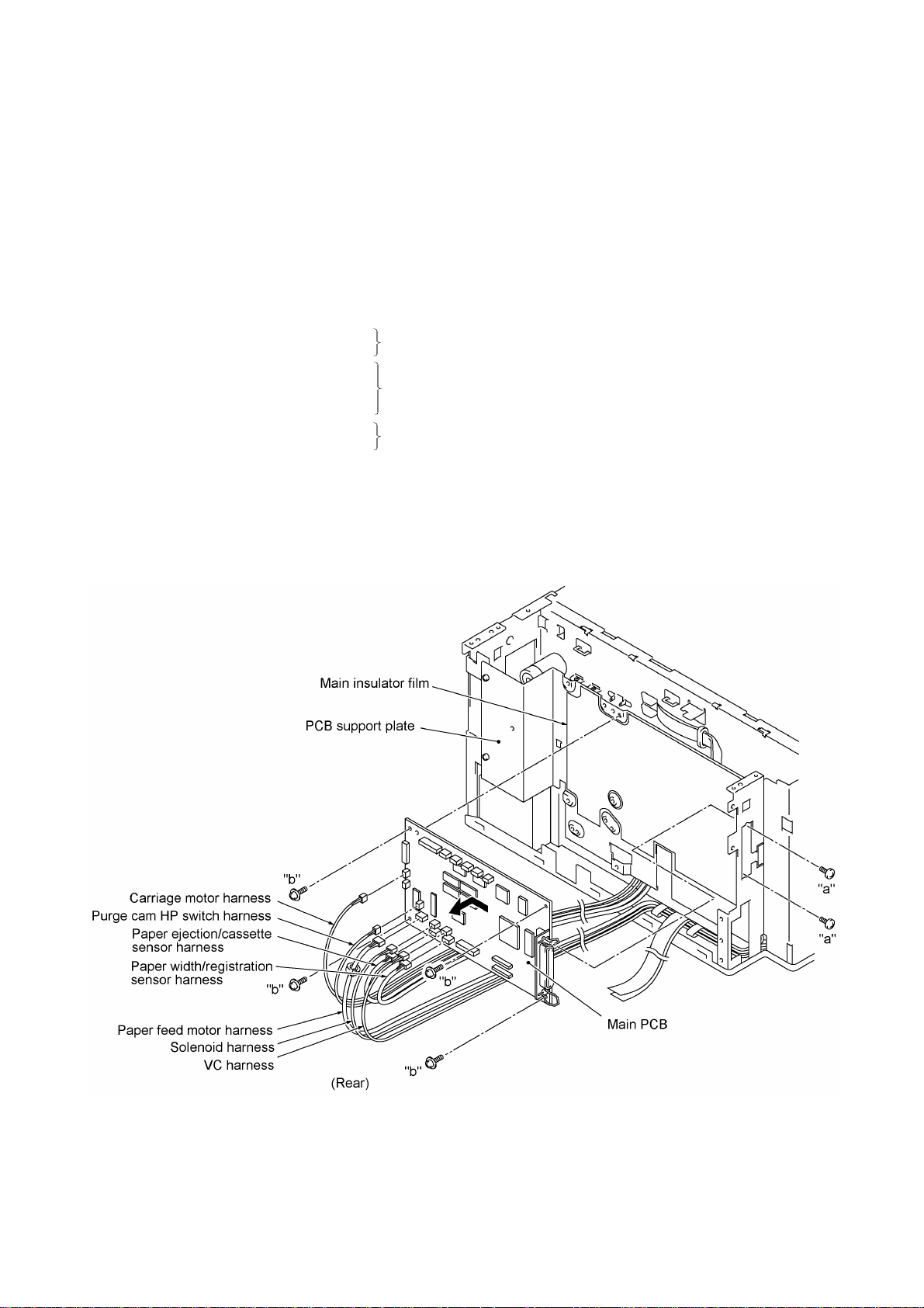
1.15 Main PCB
(1) Disconnect the following harnesses and flat cables from the main PCB:
- Carriage motor harness
- Speaker harness (if the speaker has not been removed)
- Purge cam HP switch harness
- Paper feed motor harness
- Solenoid harness
- Paper ejection/cassette sensor harness
- Paper width/registration sensor harness
- VC harness
- NCU harness
- Head flat cables
- CCD flat cable
- Panel-main harness
- CCD motor harness
- CCD HP sensor harness
- ADF motor harness
- Document sensor harness
(2) Remove two screws "a" from the interface connector.
(3) Remove four screws "b" from the main PCB.
(4) Slide the main PCB to the left (when viewed from the rear) and to the rear.
(if the NCU PCB has not been removed)
(if the scanner unit has not been removed)
(if the ADF unit has not been removed)
IV - 39
"a": Machine screw, pan M3x6
"b": Taptite, cup S M3x6
Page 81
(5) Remove the main insulator film.
nn Reassembling Notes
• After you replace the main PCB, be sure to follow the flowchart given on the next page.
IV - 40
Page 82

Setting up the main PCB after replacement
- - - - - - - - - - - - - - - - - - - - - - - - - - - - - - - - - - - - - Important - - - - - - - - - - - - - - - - - - - - - - - - - - - - - - - - - - - - - - NOTE: Before starting the following procedure, make sure that the print head unit is installed.
NOTE: When replacing the main PCB, it is recommended that you replace all ink cartridges in order to maintain
accurate ink level information.
IV - 41
Page 83

1.16 PCB Support Plate
(1) Remove the two screws from the PCB support plate.
(2) Slide the PCB support plate to the left (when viewed from the rear) and lift it up.
IV - 42
Page 84

1.17 Purge Unit
(1) Attempt to move the carriage to the left. If the carriage is locked in the home position, turn
the paper feed gear L clockwise (when viewed from the left) to retract the carriage lock (in the
direction of arrow •). Then move the carriage to the left and out of the home position (arrow
‚).
Caution
Once removed, the components given in this subsection
require the purge unit adjuster for reassembly. Refer to
Section 3, “ADJUSTMENT” in this chapter.
IV - 43
Page 85

(2) Remove the two screws from the right side of the purge unit.
(3) Pull out the purge cam HP switch harness.
(4) Slightly lift up the front end of the purge unit and take it out of the PF side frame R and main
chassis.
(5) Take off the purge cam HP switch from the purge unit by pulling the unit's latches outwards.
nn Reassembling Notes
• Make sure that the bottom end of the purge lever is placed in the left (clockwise) position when
viewed from the top. (Refer to page III-9.)
• First route the purge cam HP switch harness through the main chassis. Then put the purge unit
back into place so that the gear 20 will be placed beneath the purge switching arm (shown on
page III-9) set on the PF side frame R.
• Make sure that the purge unit is fitted in the purge unit supports provided on the PF side frame
R as illustrated above.
• After installing the purge unit, move the carriage to the right and left ends by hand to check that
it travels smoothly.
IV - 44
Page 86

1.18 Star Wheel Holder ASSY
(1) Move the carriage to either end of its travel.
(2) Insert the tip of a flat screwdriver between each latch of the star wheel holder ASSY and the
main chassis from the front and lightly twist it to unhook the latch while pulling the star wheel
holder ASSY to the rear.
IV - 45
Page 87

1.19 Platen and Its Frame
(1) Make sure that the carriage is placed in the home position.
(2) Remove the screw from the platen frame.
(3) Slightly move the platen frame to the left and take it out.
(4) Unhook the six latches of the platen from the platen frame.
IV - 46
Page 88

1.20 Flushing Foams
After the main PCB is replaced with any other one, you need to replace the flushing foams with
new ones.
(1) Remove the flushing foam gutter.
(2) Pull out the upper and lower flushing foams from the flushing foams pack.
NOTE: Use vinyl gloves to prevent your hands from becoming dirty.
NOTE: For the removal of the flushing foams pack, refer to Subsection 1.22.
IV - 47
Page 89

1.21 Main Chassis
(1) Take off the cable clip by removing the screw.
(2) Pull up the three harnesses (paper ejection/cassette sensor harness, paper width/registration
sensor harness, and carriage motor harness) released in step (1) through cutout "X" provided
in the main chassis.
(3) Pull up the head flat cables through cutout "Y" provided in the main chassis.
(4) Pull out two pieces of plastic tape as shown below to release the three harnesses (VC
harness, paper feed motor harness, and solenoid harness).
Caution
Once removed, the components given in this subsection
require the purge unit adjuster for reassembly. Refer to
Section 3, “ADJUSTMENT” in this chapter.
(5) Remove the pawled bushing from
the right end of the paper feed
gears & shaft ASSY by pulling its
pawls outwards.
(6) Remove the pawled gear 25 by
pulling its pawl outwards and pull
out the bushing.
(7) Remove the paper feed gears &
shaft ASSY.
IV - 48
Page 90

(8) Remove eight screws.
(9) Lift up the main chassis.
IV - 49
Page 91

nn Reassembling Notes
• When reinstalling the main chassis onto the paper feed frame, be sure to:
- route the carriage motor harness along the top of the main chassis and through cutout "X"
provided in the main chassis, and then tape it near the carriage motor as shown on pages
IV-49 and IV-64,
- route the paper width/registration sensor harness and paper ejection/cassette sensor
harness through cable guide "Y" provided on the upper paper chute (see page IV-70) and
cutout "X" (see page IV-49), and
- route the paper feed motor harness and VC harness through the cable clamp attached to the
NCU bracket (see page IV-36).
IV - 50
Page 92

1.22 Lower Paper Chute, Flushing Foams
Pack, Paper Ejection/Cassette Sensor
PCB, and Sensor Actuators
(1) Remove two screws.
(2) Pull the release lever to the rear and take out the lower paper chute in the direction of arrows
• and ‚.
(3) Remove the flushing foams pack.
Caution
Once removed, the components given
in this subsection require the purge unit
adjuster for reassembly. Refer to
Section 3, “ADJUSTMENT” in this
chapter.
IV - 51
Page 93

(4) As shown with arrows • and ‚, press the arm and take out the paper ejection sensor
actuator.
(5) Unhook the actuator spring and remove the cassette sensor actuator.
(6) Pull the latch and take out the paper ejection/cassette sensor PCB.
nn Reassembling Notes
• When setting the lower paper chute back into place, fully turn the arm 12.3 ASSY on the main
chassis clockwise (when viewed from the left) as shown below and pull the release lever to the
left and outwards (when viewed from the rear as shown on page IV-51).
IV - 52
Page 94

1.23 Paper Pressure Holders
(1) Remove the release lever from the main chassis.
Caution
Once removed, the components given in this
subsection require the purge unit adjuster for
reassembly. Refer to Section 3,
“ADJUSTMENT” in this chapter.
IV - 53
Page 95

(2) Remove the paper pressure holders and springs according to the instructions below.
Ÿ Start the removal work from the right-hand side holder and work your way over to the left-
hand side, when viewed from the rear.
Ÿ Unhook the top end of the spring from the main frame (in the direction of arrow •), shift
the paper pressure holder to the right and pull it out to the rear (arrow ‚).
nn Reassembling Notes
• The paper pressure holders to be placed in the 1st and 5th positions are different in shape with
each other and different from other three.
• After installing the paper pressure holders, their springs, and the release lever, pull up the
release lever to check that it works normally.
IV - 54
Page 96

1.24 Paper Feed Motor, Paper Feed Gear L, PF Drive Belt, and Tension Plate ASSY
(1) Loosen screw "a" on the tension plate ASSY.
(2) Remove two screws "b" that secures the paper feed motor.
(3) Turn the tension plate ASSY counterclockwise and pull the paper feed motor inwards.
IV - 55
"a" and "b": Screw, pan (washer) M3x8DB
Page 97

(4) Remove the retaining ring E8, paper feed gear L, and spacer from the left side of the main
chassis.
(5) Remove the tension spring.
(6) Remove the PF drive belt from the idle gear 720.
(7) Remove the retaining ring E4 and idle gear 720.
(8) Remove screw "a," retaining ring E3, and tension plate ASSY.
nn Reassembling Notes
• When reinstalling the tension plate ASSY, idle gear 720, and PF drive belt, follow the steps
below.
1) Secure the tension plate ASSY to the left side of the main chassis with retaining ring E3
and turn it counterclockwise (in the direction of arrow •).
2) Secure the idle gear 720 with the retaining ring E4 (arrows ‚ and ƒ).
IV - 56
Page 98

3) Secure the paper feed motor with two screws "b" (refer to the illustration given on page IV-
55).
4) Put the PF drive belt around the paper feed motor gear and the idle gear 720.
5) Turn the tension plate ASSY clockwise (in the direction of arrow •) to apply tension to the
PF drive belt and set the tension spring onto the three hooks (arrow ‚).
6) Secure the tension plate ASSY to the main frame with screw "a" (arrow ƒ).
IV - 57
Page 99

1.25 Arm 12.3 ASSY and
Paper Feed Roller
(1) Make sure that the carriage is placed in the home position.
(2) Remove the retaining ring E4 from the arm 12.3 ASSY and take it off from the main chassis.
Caution
Once removed, the components given in this
subsection require the purge unit adjuster for
reassembly. Refer to Section 3,
“ADJUSTMENT” in this chapter.
(3) Remove the retaining ring E8 from the left end of the paper feed roller shaft inside the main
chassis.
(4) Take out the paper feed roller in the direction of the arrow.
IV - 58
Page 100

1.26 Paper Ejection Roller
(1) Make sure that the carriage is placed in the home position.
(2) Remove the paper ejection idle gear by pulling its pawl outwards.
(3) Remove the screw from the paper ejection roller gear.
(4) Take out the paper ejection roller with the bushing in the direction of the arrow.
(5) Push the pawl of the paper ejection roller gear and remove it to the left.
IV - 59
 Loading...