

Brother LT2-B847 MKII Owner's Manual
INSTRUCTION MANUAL
BAS-300G-484
BAS-300G-484 SF
Please read this manual before using the machine.
Please keep this manual within easy reach for quick reference.
DIRECT DRIVE
PROGRAMMABLE ELECTRONIC PATTERN SEWER
<TREBLE HOOK>

Thank you very much for buying a BROTHER sewing machine. Before using your new machine,
please read the safety instructions below and the explanations given in the instruction manual.
With industrial sewing machines, it is normal to carry out work while positioned directly in front of
moving parts such as the needle and thread take-up lever, and consequently there is always a
danger of injury that can be caused by these parts. Follow the instructions from training personnel
and instructors regarding safe and correct operation before operating the machine so that you will
know how to use it correctly.
BAS-300G-484, BAS-300G-484 SF
SAFETY INSTRUCTIONS
[1] Safety indications and their meanings
This instruction manual and the indications and symbols that are used on the machine itself are provided in order to ensure
safe operation of this machine and to prevent accidents and injury to yourself or other people.
The meanings of these indications and symbols are given below.
Indications
DANGER
The instructions which follow this term indicate situations where failure to follow the
instructions will result in death or serious injury.
WARNING
CAUTION
Symbols
・・・・・・
・・・・・・
・・・・・・
The instructions which follow this term indicate situations where failure to follow the
instructions could result in death or serious injury.
The instructions which follow this term indicate situations where failure to follow the
instructions may result in minor or moderate injury.
This symbol ( ) indicates something that you should be careful of. The picture inside the triangle
indicates the nature of the caution that must be taken.
(For example, the symbol at left means “beware of injury”.)
This symbol ( ) indicates something that you must not do.
This symbol ( ) indicates something that you must do. The picture inside the circle indicates the
nature of the thing that must be done.
(For example, the symbol at left means “you must make the ground connection”.)
BAS-300G-484, BAS-300G-484 SF
i
[2] Notes on safety
Wait at least 5 minutes after turning off the power switch and disconnecting the power cord from the wall outlet
before opening the control box cover. Touching areas where high voltages are present will result in serious injury
from electric shocks.
Do not allow any liquids to get onto this sewing machine, otherwise fire, electric shocks or operating problems may
occur.
If any liquid gets inside the sewing machine (machine head or control box), immediately turn off the power and
disconnect the power plug from the electrical outlet, and then contact the place of purchase or a qualified
technician.
DANGER
WARNING
CAUTION
Environmental requirements
Use the sewing machine in an area which is free from
sources of strong electrical noise such as electrical
line noise or static electric noise.
Sources of strong electrical noise may cause
problems with correct operation.
Any fluctuations in the power supply voltage should
be within ±10% of the rated voltage for the machine.
Voltage fluctuations which are greater than this may
cause problems with correct operation.
The power supply capacity should be greater than the
requirements for the sewing machine's power
consumption.
Insufficient power supply capacity may cause
problems with correct operation.
Installation
Machine installation should only be carried out by a
qualified technician.
Contact your Brother dealer or a qualified electrician
for any electrical work that may need to be done.
The sewing machine weighs approximately 90 kg.
The installation should be carried out by two or more
people.
Do not connect the power cord until installation is
complete. If the foot switch is depressed by mistake,
the sewing machine might start operating and injury
could result.
Hold the machine head with both hands when tilting it
back or returning it to its original position.
Furthermore, do not apply excessive force when
tilting back the machine head. The sewing machine
may become unbalanced and fall down, and serious
injury or damage to the sewing machine may result.
Be sure to connect the ground. If the ground
connection is not secure, you run a high risk of
receiving a serious electric shock, and problems with
correct operation may also occur.
The pneumatic delivery capability should be greater
than the requirements for the sewing machine's total
air consumption.
Insufficient pneumatic delivery capability may cause
problems with correct operation.
The ambient temperature should be within the range
of 5°C to 35°C during use.
Temperatures which are lower or higher than this
may cause problems with correct operation.
The relative humidity should be within the range of
45% to 85% during use, and no dew formation should
occur in any devices.
Excessively dry or humid environments and dew
formation may cause problems with correct operation.
In the event of an electrical storm, turn off the power
and disconnect the power cord from the wall outlet.
Lightning may cause problems with correct operation.
All cords should be secured at least 25 mm away
from any moving parts. Furthermore, do not
excessively bend the cords or secure them too firmly
with staples, otherwise there is the danger that fire or
electric shocks could occur.
Install the safety covers to the machine head and
motor.
If using a work table which has casters, the casters
should be secured in such a way so that they cannot
move.
Be sure to wear protective goggles and gloves when
handling the lubricating oil and grease, so that they
do not get into your eyes or onto your skin. If the oil
and grease get into your eyes or onto your skin,
inflammation can result.
Furthermore, do not drink or eat the lubricating oil or
grease. They may cause diarrhea or vomiting.
Keep the oil out of the reach of children.
ii
BAS-300G-484, BAS-300G-484 SF
CAUTION
Sewing
This sewing machine should only be used by
operators who have received the necessary training
in safe use beforehand.
The sewing machine should not be used for any
applications other than sewing.
Be sure to wear protective goggles when using the
machine.
If goggles are not worn, there is the danger that if a
needle breaks, parts of the broken needle may enter
your eyes and injury may result.
Turn off the power switch at the following times. If the
foot switch is depressed by mistake, the sewing
machine might start operating and injury could result.
• When threading the needle
• When replacing the bobbin and needle
• When not using the machine and when leaving the
machine unattended
Cleaning
Turn off the power switch before carrying out
cleaning. If the foot switch is depressed by mistake,
the sewing machine might start operating and injury
could result.
If using a work table which has casters, the casters
should be secured in such a way so that they cannot
move.
Attach all safety devices before using the sewing
machine. If the machine is used without these
devices attached, injury may result.
Do not touch any of the moving parts or press any
objects against the machine while sewing, as this
may result in personal injury or damage to the
machine.
If an error occurs in machine operation, or if abnormal
noises or smells are noticed, immediately turn off the
power switch. Then contact your nearest Brother
dealer or a qualified technician.
If the machine develops a problem, contact your
nearest Brother dealer or a qualified technician.
Be sure to wear protective goggles and gloves when
handling the lubricating oil and grease, so that they
do not get into your eyes or onto your skin. If the oil
and grease get into your eyes or onto your skin,
inflammation can result.
Furthermore, do not drink or eat the lubricating oil or
grease. They may cause diarrhea or vomiting.
Keep the oil out of the reach of children.
Maintenance and inspection
Maintenance and inspection of the sewing machine
should only be carried out by a qualified technician.
Ask your Brother dealer or a qualified electrician to
carry out any maintenance and inspection of the
electrical system.
Turn off the power switch and disconnect the power
cord before carrying out the following operations. If
the foot switch is depressed by mistake, the sewing
machine might start operating and injury could result.
• Inspection, adjustment and maintenance
• Replacing consumable parts such as the rotary
hook
Disconnect the air hoses from the air supply and wait
for the needle on the pressure gauge to drop to “0”
before carrying out inspection, adjustment and repair
of any parts which use the pneumatic equipment.
Hold the machine head with both hands when tilting it
back or returning it to its original position.
Furthermore, do not apply excessive force when
tilting back the machine head. The sewing machine
may become unbalanced and fall down, and serious
injury or damage to the sewing machine may result.
If the power switch needs to be left on when carrying
out some adjustment, be extremely careful to observe
all safety precautions.
When replacing parts and installing optional
accessories, be sure to use only genuine Brother
parts.
Brother will not be held responsible for any accidents
or problems resulting from the use of non-genuine
parts.
If any safety devices have been removed, be
absolutely sure to re-install them to their original
positions and check that they operate correctly before
using the machine.
To prevent accidents and problems, do not modify
the machine yourself.
Brother will not be held responsible for any accidents
or problems resulting from modifications made to the
machine.
BAS-300G-484, BAS-300G-484 SF
iii
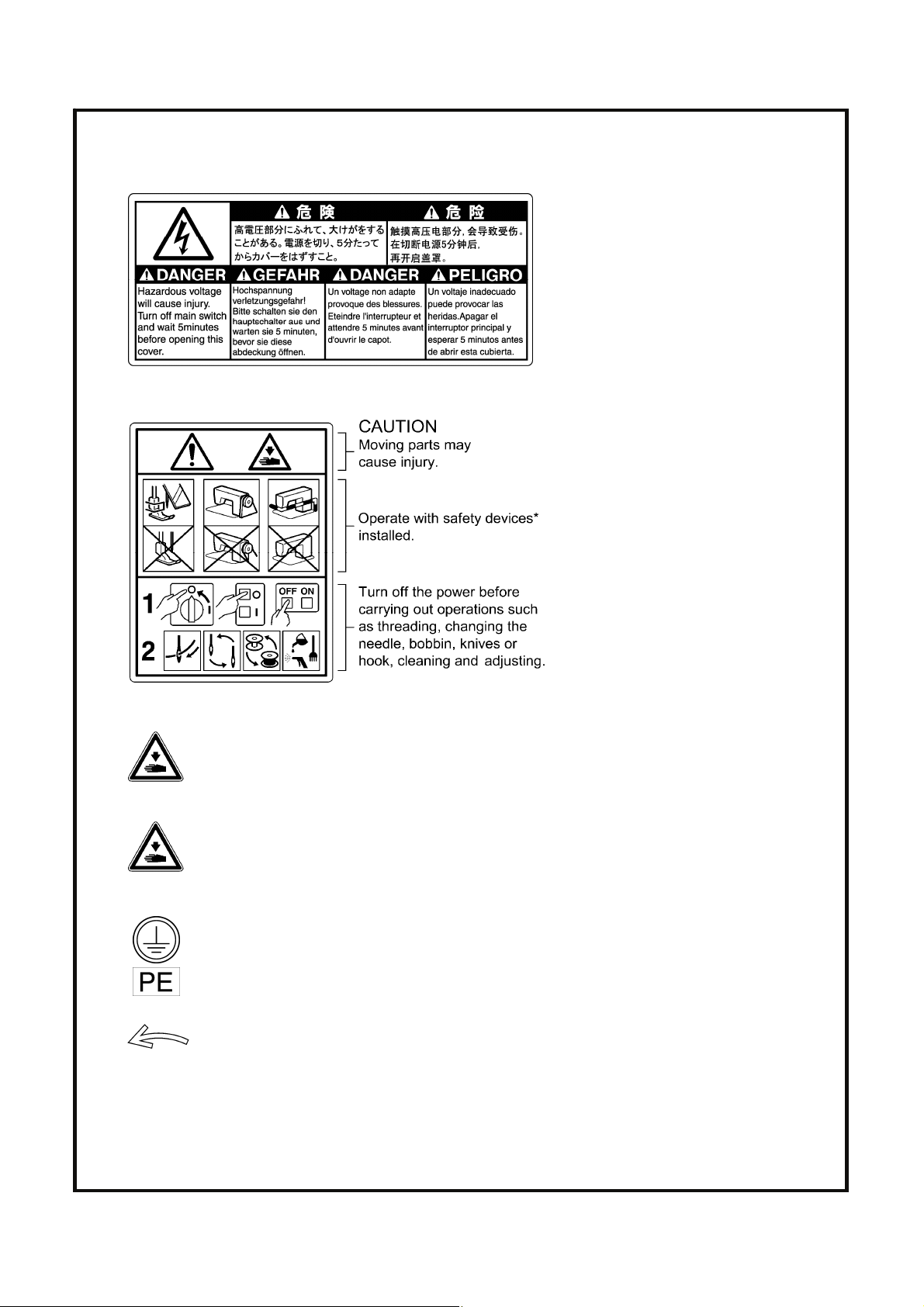
[3] Warning labels
The following warning labels appear on the sewing machine.
Please follow the instructions on the labels at all times when using the machine. If the labels have been removed or are
difficult to read, please contact your nearest Brother dealer.
1
2
3
Be careful not to get your hand caught when tilting back the machine head and returning it to its
original position.
*Safety devices
Devices such as eye guard, finger
guard, thread take-up cover, motor
cover, solenoid cover, tension release
solenoid cover, inner cover, outer
cover, fixed cover, gas spring support
cover and hook cover
iv
4
5
6
When operating the sewing machine, close the hook cover.
If you touch the hook while it is spinning, injury or damage to the sewing machine may result.
Be sure to connect the ground. If the ground connection is not secure, you run a high risk of receiving
a serious electric shock, and problems with correct operation may also occur.
Direction of operation
BAS-300G-484, BAS-300G-484 SF
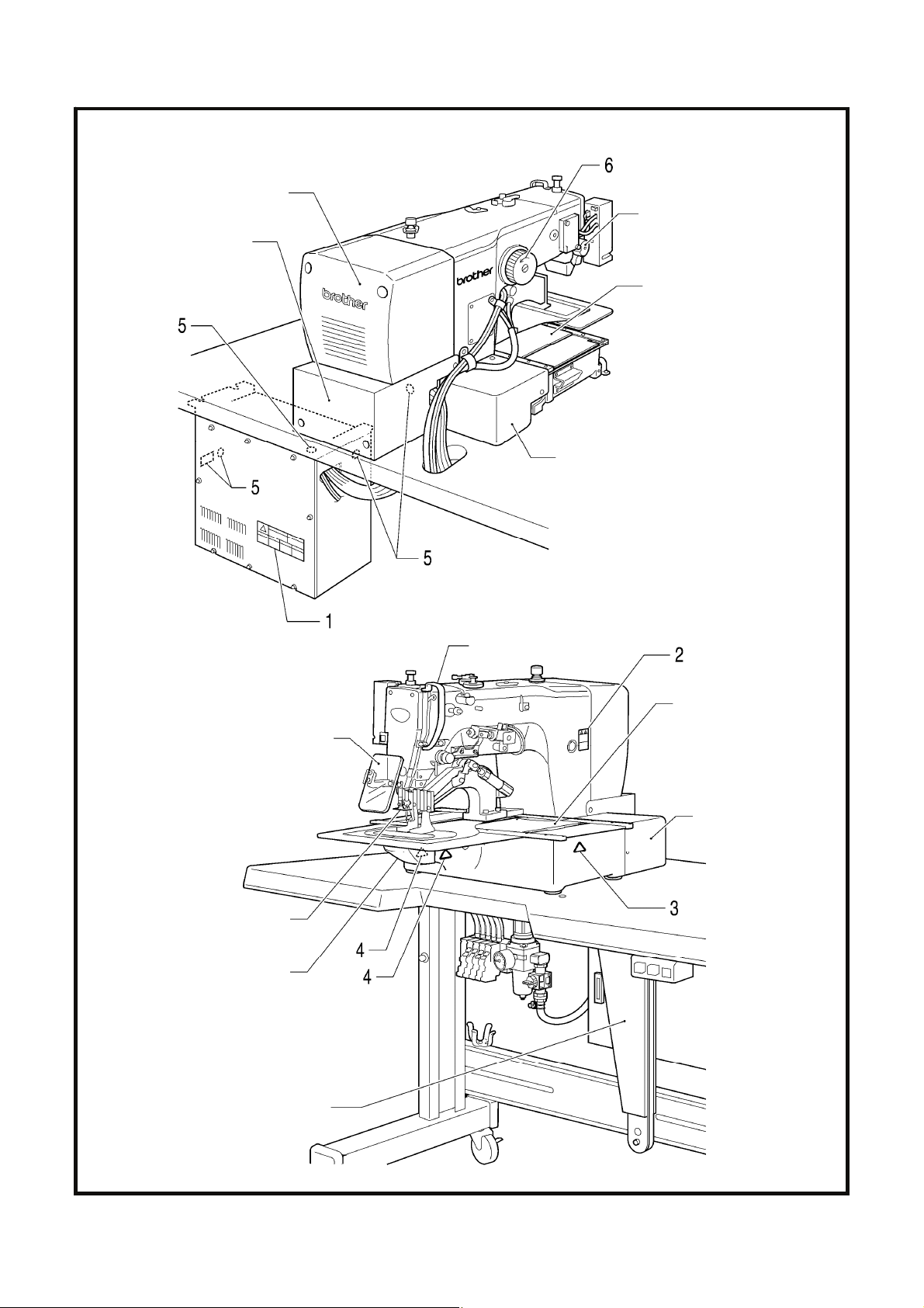
Solenoid cover
Motor cover
Tension release solenoid cover
Motor cover L
Inner cover L
Outer cover
Fixed cover L
Eye guard
Finger guard
Hook cover
Thread take-up cover
Inner cover R
Outer cover
Fixed cover R
Motor cover R
Gas spring support cover
4630M 4631M
BAS-300G-484, BAS-300G-484 SF
v

CONTENTS
1. NAMES OF MAJOR PARTS ................ 1
2. SPECIFICATIONS ................................ 2
3. INSTALLATION.................................... 3
3-1. Table processing diagram ................................ 3
3-2. Installing the control box................................... 4
3-3. Installing the oil pan.......................................... 4
3-4. Installing the machine head.............................. 5
3-5. Tilting the sewing machine head ...................... 9
3-6. Installing the operation panel............................ 9
3-7. Installing the pneumatic unit ............................. 10
3-8. Adjusting the speed controller .......................... 11
3-9. Connecting the cords........................................ 12
3-10. Connecting the ground wire............................ 14
3-11. Connecting the power cord............................. 15
3-12. Installing the cotton stand...............................15
3-13. Installing the eye guard .................................. 16
3-14. Installing the motor cover ............................... 17
3-15. Lubrication ...................................................... 18
3-16. Installing the machine head fixing bolt ........... 19
4. PREPARATION BEFORE SEWING.....20
4-1. Installing the needle.......................................... 20
4-2. Threading the upper thread .............................. 20
4-3. Foot switch operating method ..........................21
4-4. Winding the lower thread..................................22
4-5. Installing the bobbin case................................. 23
4-6. Installing the anti-spin spring............................ 23
4-7. Thread tension.................................................. 24
4-7-1. Lower thread tension ............................. 24
4-7-2. Upper thread tension ............................. 24
4-8. Home position detection ................................... 25
5. USING THE OPERATION PANEL
(BASIC OPERATIONS)....................... 26
5-1. Name and function of each operation
panel item.........................................................26
5-2. Loading sewing data......................................... 28
5-3. Setting the program number.............................28
5-4. Setting the X-scale and Y-scale .......................29
5-5. Setting the sewing speed..................................29
5-6. Checking the sewing pattern ............................30
5-7. Setting the height of the intermittent
presser foot (-484 SF specifications only)........31
6. USING THE OPERATION PANEL
(ADVANCED OPERATIONS).............. 32
6-1. List of advanced functions ................................ 32
6-2. Setting memory switches..................................33
6-3. List of memory switch settings..........................34
6-4. Using the lower thread counter......................... 35
6-5. Using the production counter............................ 36
6-6. Setting the split number....................................37
6-7. Using user programs ........................................38
6-8. Using cycle programs ....................................... 41
6-9. Direct selection (combination table) .................43
6-10. X and Y parallel movement
of sewing pattern ............................................44
6-11. Clearing memory data (reinitialization) ........... 45
7. USING CF CARDS............................... 46
7-1. Notes on handling CF cards (sold separately)
..........................................................................46
7-2. Structure of a CF card folder ............................46
7-3. Data read/write mode .......................................47
7-3-1. Reading all sewing data from the
CF card at once ...................................... 48
7-3-2. Writing all sewing data to the CF card at
once ........................................................49
BAS-300G-484, BAS-300G-484 SF

8. SEWING................................................50
8-1. Sewing .............................................................. 50
8-2. Using the STOP switch..................................... 51
8-3. Using the thread wiper switch........................... 51
9. CLEANING ...........................................52
9-1. Cleaning the rotary hook ..................................52
9-2. Cleaning the control box air inlet ports ............. 52
9-3. Draining the oil.................................................. 53
9-4. Checking the regulator ..................................... 53
9-5. Cleaning the eye guard .................................... 53
9-6. Checking the needle.........................................53
9-7. Lubrication ........................................................ 53
10. STANDARD ADJUSTMENTS ............54
10-1. Checking the machine head switch................ 54
10-2. Arm thread guide R ........................................ 54
10-3. Thread take-up spring .................................... 55
10-4. Adjusting the needle bar height...................... 55
10-5. Adjusting the needle bar lift amount ............... 56
10-6. Adjusting the needle clearance ...................... 56
10-7. Adjusting the thread take-up amount ............. 57
10-8. Adjusting the clearance between the inner
hook and the hook stopper............................. 57
10-9. Replacing the movable and fixed knives ........ 58
10-10. Adjusting the standby position of the
movable knife................................................ 59
10-11. Adjusting the engagement of the
movable knife and fixed knife ....................... 61
10-12. Installing the feed plate................................. 62
10-13. Adjusting the thread wiper............................ 63
10-14. Intermittent presser foot installation
position (-484 SF specifications only) .......... 63
10-15. Changing the intermittent stroke
(-484 SF specifications only) ........................ 64
10-16. Adjusting the work clamp lift amount............66
10-17. Adjusting the air pressure............................. 66
10-18. If processing the work clamps and the feed
plate to a shape that matches the sewing
pattern........................................................... 67
11. TABLE OF ERROR CODES .............. 68
12. TROUBLESHOOTING ....................... 73
13. 7-SEGMENT DISPLAY ...................... 77
BAS-300G-484, BAS-300G-484 SF
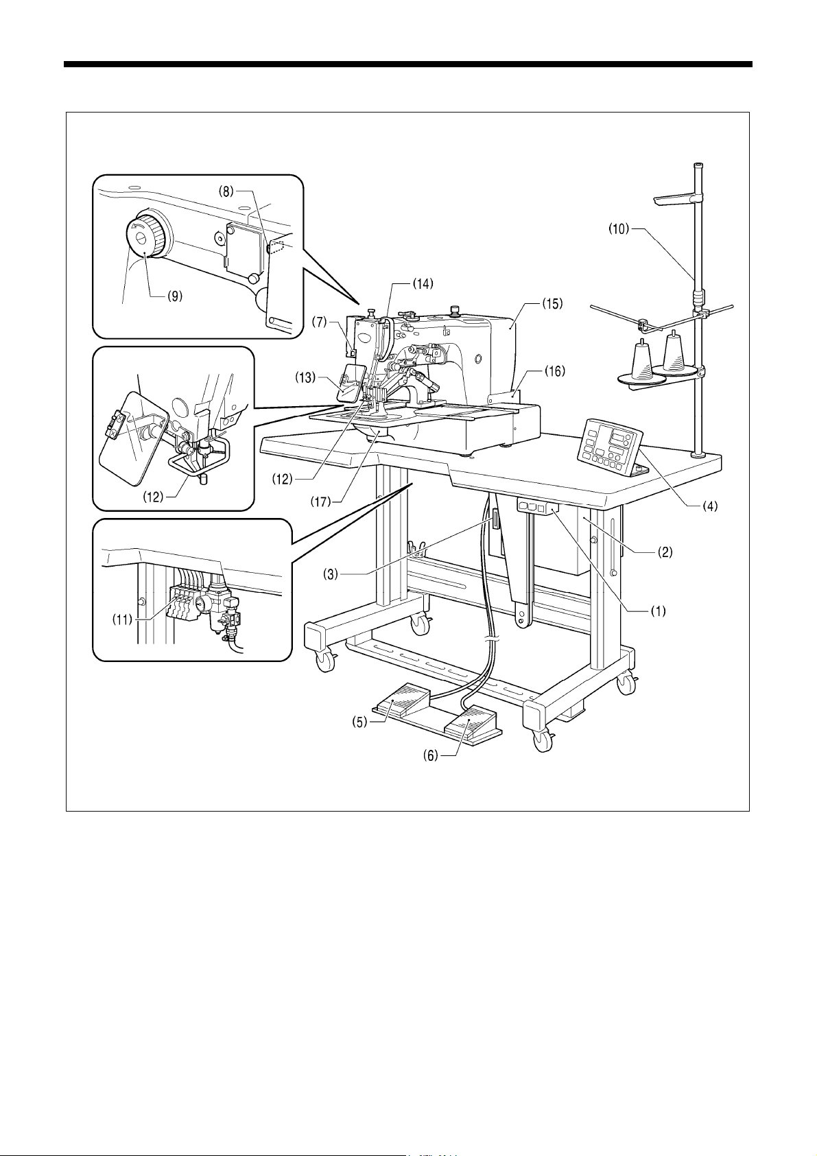
1. NAMES OF MAJOR PARTS
1. NAMES OF MAJOR PARTS
(1) Power switch
(2) Control box (12) Finger guard
(3) CF slot (13) Eye guard
(4) Operation panel (14) Thread take-up cover
(5) Work clamp switch (15) Motor cover
(6) Start switch (16) Solenoid cover
(7) STOP switch (17) Hook cover
(8) Thread wiper switch
(9) Pulley
(10) Cotton stand
(11) Solenoid valve
CF
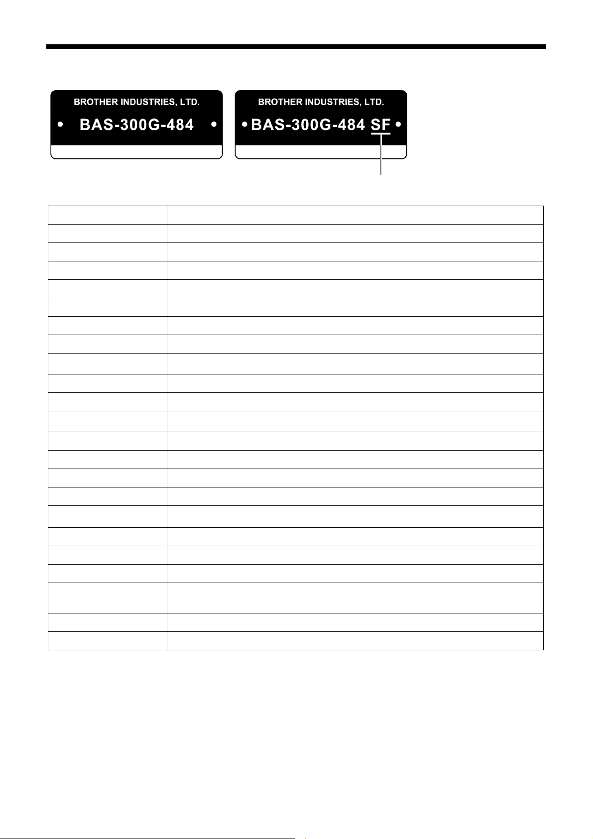
<BAS-300G-484>
TM
is a trademark of SanDisk Corporation.
<BAS-300G-484 SF>
4632M
Safety devices:
1
BAS-300G-484, BAS-300G-484 SF
2. SPECIFICATIONS
Sewing machine Lock stitch pattern tacking sewing machine
Stitch formation Single needle lock stitch
Max. sewing speed 2,200 sti/min
Max. sewing area (XxY) 130 x 60 mm
Feed mechanism Intermittent feed, pulse motor drive
With intermittent presser foot
2. SPECIFICATIONS
4633M
Stitch length
No. of stitches 500,000-stitch internal memory (*1)
Maximum no. of stitches 20,000 stitches (per program)
No. of sewing data items
that can be stored
Work clamp lift method Pneumatic method
Work clamp height Max. 30 mm
Intermittent presser foot lift
amount
Intermittent stroke
Hook Treble hook
Wiper device Standard equipment
Thread trimmer Standard equipment
Data storage method
User programs 50
Cycle programs 9
Motor 550 W AC servo motor
Weights
2 − 4.5 mm, 4.5 − 10 mm or 0 (Default setting 3 mm) (*2)
Internal memory (Flash memory), CF card (32 MB − 2 GB)
Machine head approx. 90 kg, operation panel approx. 0.6 kg
Control box 14.2 − 16.2 kg (Differs depending on destination)
Internal memory: 512 (*1), CF card: 900
3.5 floppy disk 2HD/1.44MB, 2DD (*3)
0.05 − 12.7 mm
19.5 mm (*2)
Power supply Single-phase 110 V/120 V/220 V/240 V, Three-phase 220 V/400 V 400 VA
Air pressure 0.5 MPa 1.8 l/min.
(*1) The number of data items and stitches that can be stored will vary depending on the number of stitches in each
program.
(*2) Only applicable to -484 SF specifications.
(*3) Supply of parts relating to 3.5-inch floppy disks has already been discontinued. (However the mechanism will still
function.)
BAS-300G-484, BAS-300G-484 SF
2
3. INSTALLATION
3. INSTALLATION
CAUTION
Machine installation should only be carried out by a
qualified technician.
Contact your Brother dealer or a qualified electrician
for any electrical work that may need to be done.
The sewing machine head weighs approximately 90
kg. The installation should be carried out by two or
more people.
Do not connect the power cord until installation is
complete.
If the foot switch is depressed by mistake, the sewing
machine might start operating and injury could result.
Hold the machine head with both hands when tilting it
back or returning it to its original position.
Furthermore, do not apply excessive force when tilting
back the machine head. The sewing machine may
become unbalanced and fall down, and serious injury
or damage to the sewing machine may result.
All cords should be secured at least 25 mm away from
any moving parts. Furthermore, do not excessively
bend the cords or secure them too firmly staples,
otherwise there is the danger that fire or electric
shocks could occur.
Be sure to connect the ground. If the ground
connection is not secure, you run a high risk of
receiving a serious electric shock, and problems with
correct operation may also occur.
Install the safety covers to the machine head and
motor.
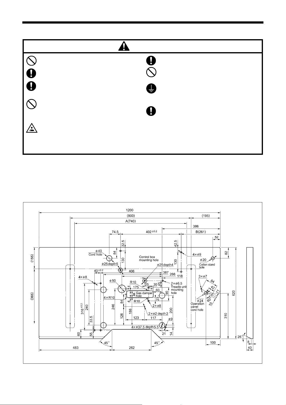
3-1. Table processing diagram
• The thickness of the table should be at least 40 mm, and it should be strong enough to bear the weight and vibration of the
sewing machine.
• If the distance A between the insides of the legs is less than 740 mm, move the control box installation position to the left (B =
261 mm).
• Check that the control box is at least 10 mm away from the leg. If the control box and the leg are too close together, it may result
in incorrect sewing machine operation.
4718M
3
BAS-300G-484, BAS-300G-484 SF
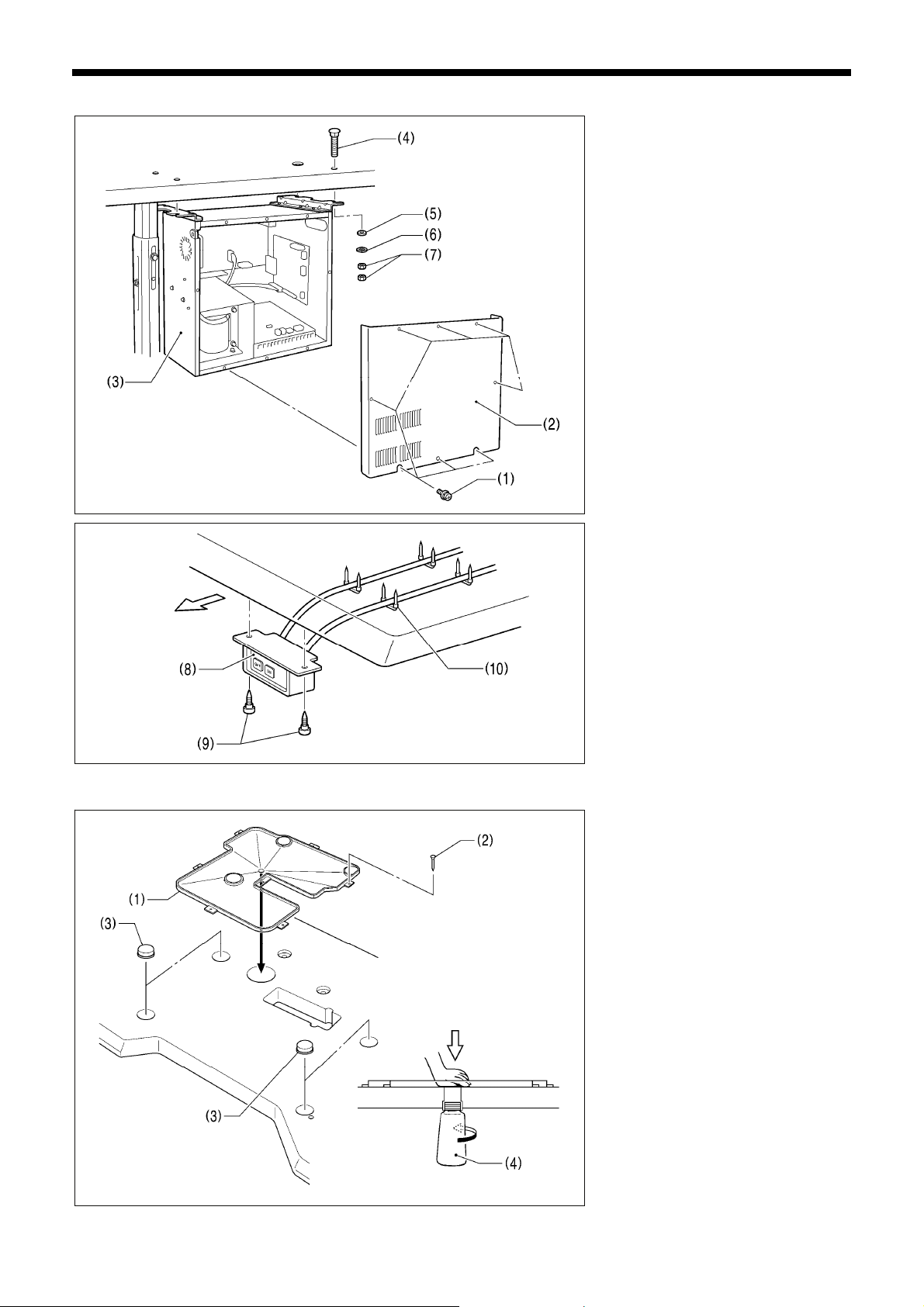
3-2. Installing the control box
Operator
3-3. Installing the oil pan
3. INSTALLATION
Remove the eight screws (1), and then
remove the control box cover (2).
(3) Control box
(4) Bolts [4 pcs.]
(5) Plain washers [4 pcs.]
(6) Spring washers [4 pcs.]
(7) Nuts [8 pcs.]
1840B
(8) Power switch
(9) Wood screws [2 pcs.]
(10) Staples [4 pcs.]
1841B
(1) Oil pan
(2) Nails [7 pcs.]
(3) Rubber cushions [4 pcs.]
(4) Waste oil tank
2142B
BAS-300G-484, BAS-300G-484 SF
4
3. INSTALLATION
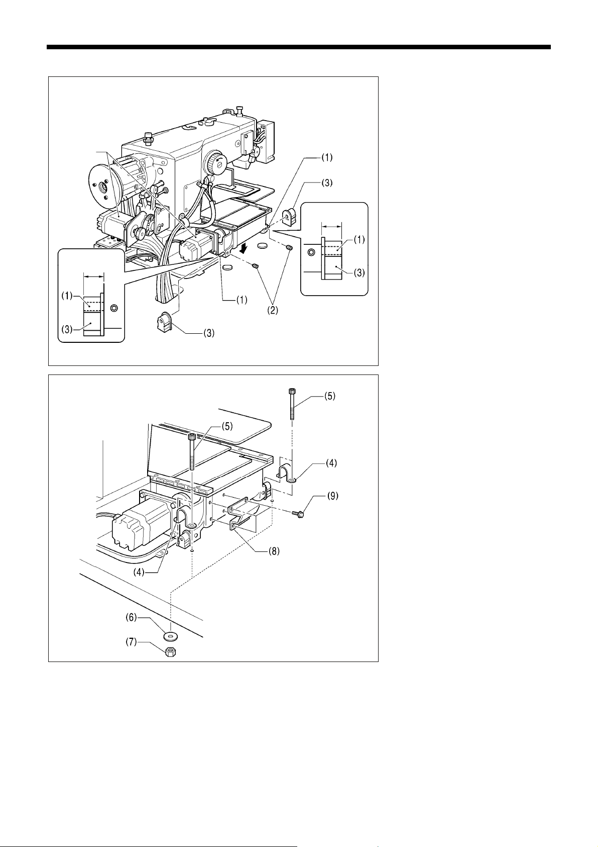
3-4. Installing the machine head
(1) Pins [2 pcs.]
(2) Set screws [2 pcs.]
(3) Hinge rubber assemblies [2 pcs.]
Place the machine head gently on top of
the oil pan and the rubber cushions.
Pulse motor
Approx. 20 mm
Approx. 20 mm
4635M
NOTE:
• Be careful not to get the cords
clamped between the machine head
and the oil pan.
• When holding the machine head, do
not hold it by the pulse motor. This
may cause problems with operation
of the pulse motor.
(4) Hinge holders [2 pcs.]
(5) Bolts [4 pcs.]
(6) Plain washers [4 pcs.]
(7) Nuts [4 pcs.]
(8) Head rest
(9) Bolts with washer [4 pcs.]
5
4636M
BAS-300G-484, BAS-300G-484 SF
Needle plate
3. INSTALLATION
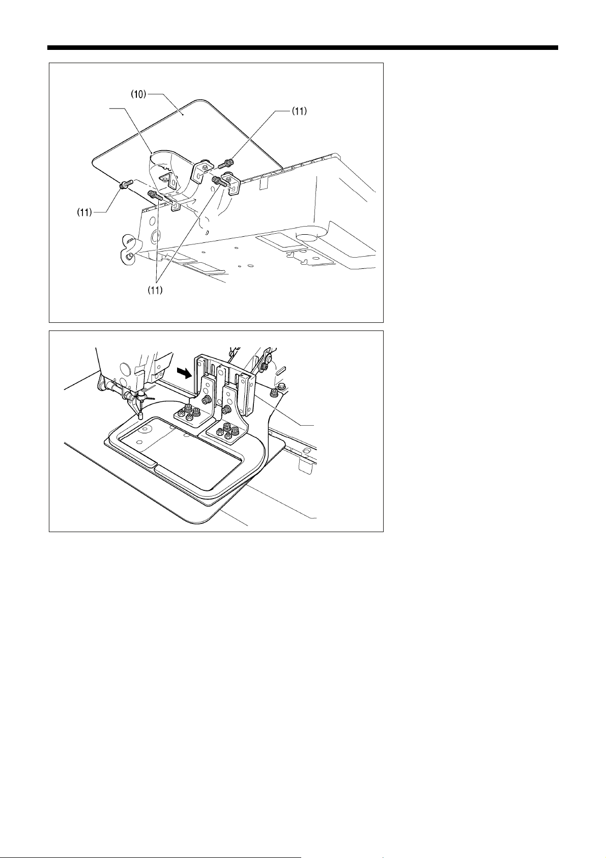
(10) Auxiliary plate
(11) Bolts with washer [4 pcs.]
Loosen the four bolts with washer (11),
and adjust so that the auxiliary plate (10)
is 0 to 0.5 mm above the needle plate.
NOTE:
Install the auxiliary plate (10) so that it
is horizontal.
If the auxiliary plate (10) is lower than
the needle plate, the feed plate may
get caught on the needle plate.
4637M
Move the work clamp arm all the way to
the right when looking from the front of
the sewing machine (the direction of the
arrow in the illustration), and then gently
tilt back the machine head.
NOTE:
Two or more people should tilt back the
Work clamp arm
machine head, and it should be tilted
gently while being held with both
hands.
4638M
BAS-300G-484, BAS-300G-484 SF
6
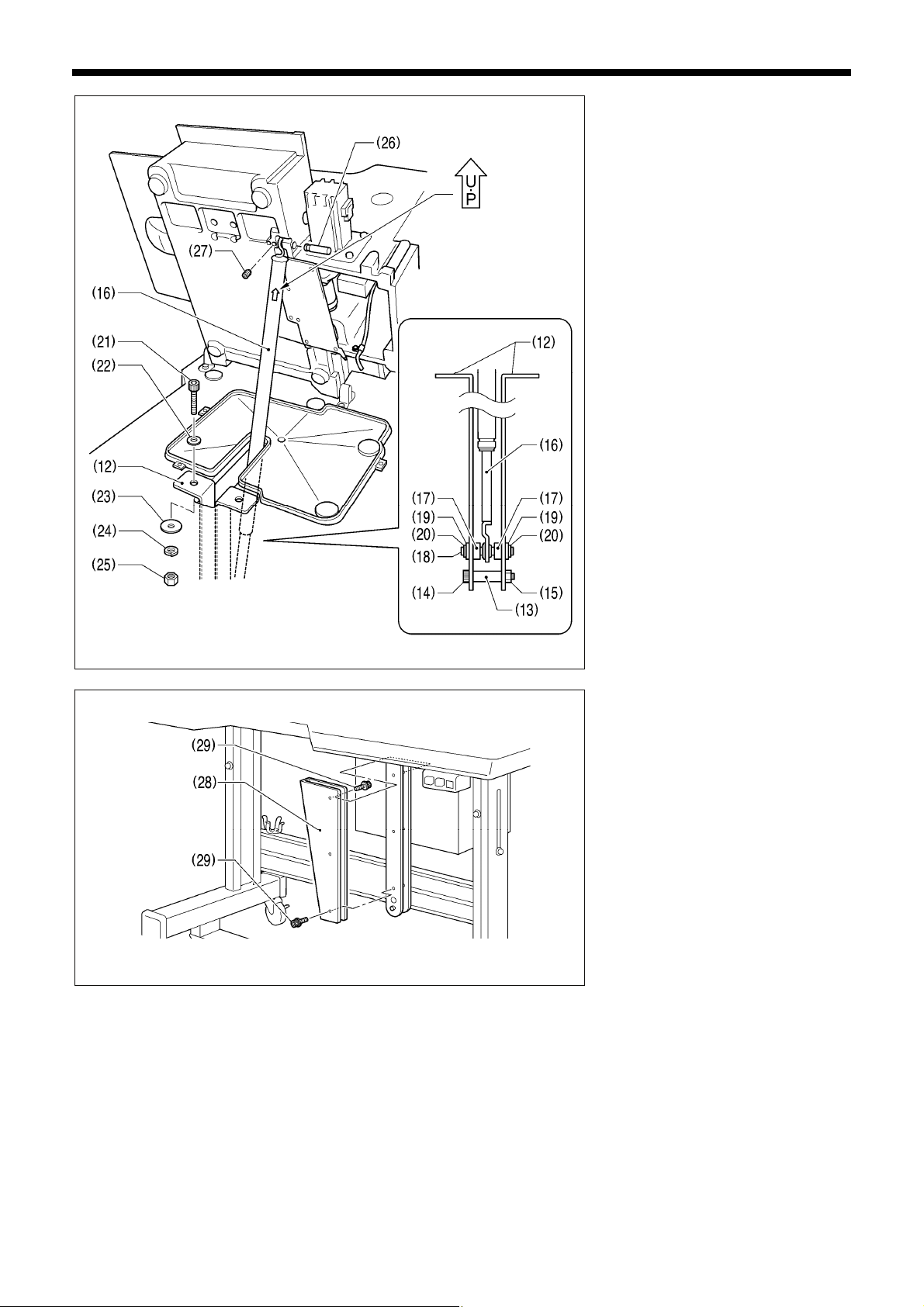
3. INSTALLATION
4639M
Be sure to install so
that the side with “UP”
on it is facing upward.
4640M
(12) Gas spring holders [2 pcs.]
(13) Spacer
(14) Bolt
(15) Nut
(16) Gas spring
(17) Shaft collars [2 pcs.]
(18) Gas spring shaft D
(19) Plain washers [2 pcs.]
(20) Retaining rings E [2 pcs.]
(21) Bolts [2 pcs.]
(22) Plain washers (medium) [2 pcs.]
(23) Plain washers (large) [2 pcs.]
(24) Spring washers [2 pcs.]
(25) Nuts [2 pcs.]
(26) Gas spring shaft U
(27) Set screw
(28) Gas spring support cover
(29) Bolts with washer [6 pcs.]
7
BAS-300G-484, BAS-300G-484 SF
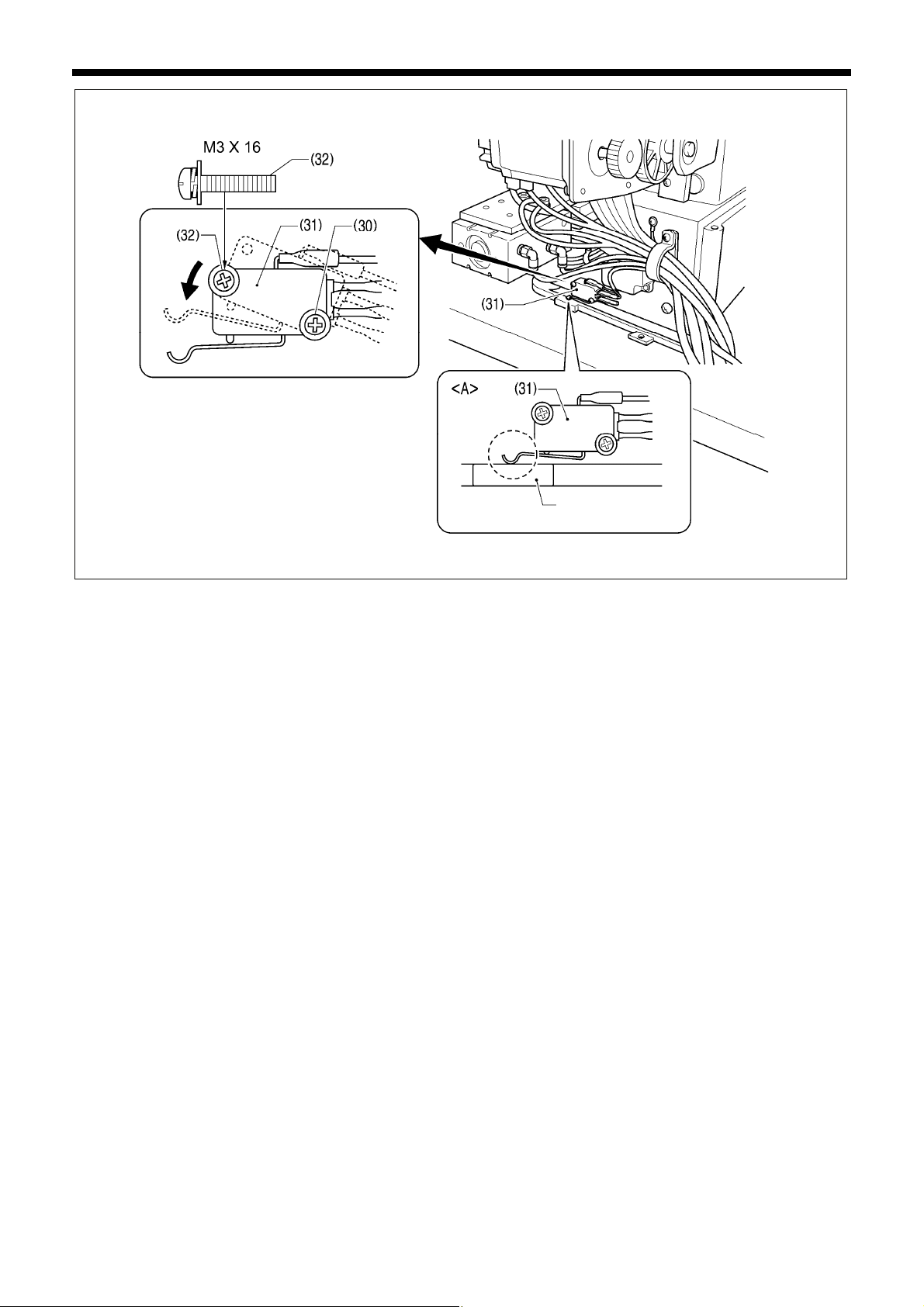
3. INSTALLATION
Oil pan
4641M
• Gently return the machine head to its original position.
• Loosen the screw (30). Move the machine head switch (31) to the position shown in the illustration, and then secure the machine
head switch (31) with the screw (30) and the accessory M3x16 screw (32).
• Check that the machine head switch (31) is turned on as shown in figure <A>.
NOTE:
If the machine head switch is not turned on, errors "E050", "E051" and "E055" will be generated.
BAS-300G-484, BAS-300G-484 SF
8
3. INSTALLATION
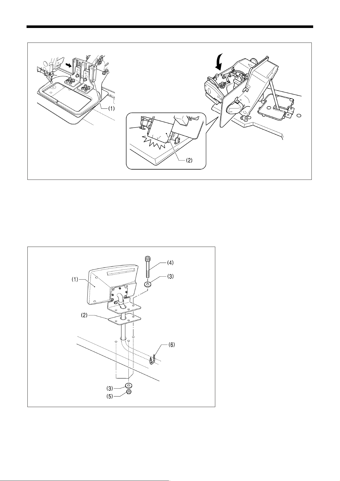
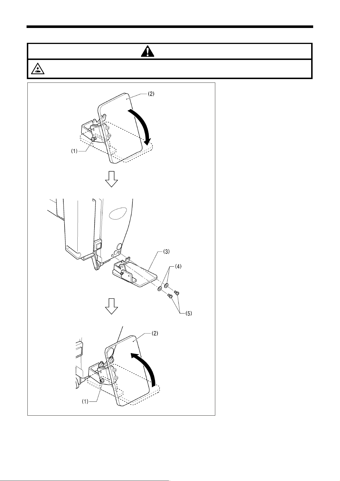
3-5. Tilting the sewing machine head
4642M 4643M
1. Move the presser arm assembly (1) as far as it will go in the direction of the arrow in the illustration (to the right when looking
from the front of the sewing machine).
2. Stand at the left side of the table, and gently tilt the machine head towards you.
<CAUTION>
NOTE:
Always be sure to move the work clamp arm (1) all the way to the right before tilting back the machine head. If you try to tilt back
the machine head while the work clamp arm (1) is still on the left side, it may damage the outer cover L (2).
3-6. Installing the operation panel
(1) Operation panel set
(2) Panel rubber
(3) Plain washers [6 pcs.]
(4) Bolts [3 pcs.]
(5) Nuts [6 pcs.]
• Insert the cord from the operation
panel (1) which has been passed
through the hole in the table into the
control box through the hole in the
side of the control box.
(6) Staples [3 pcs.]
9
2971B
BAS-300G-484, BAS-300G-484 SF
A
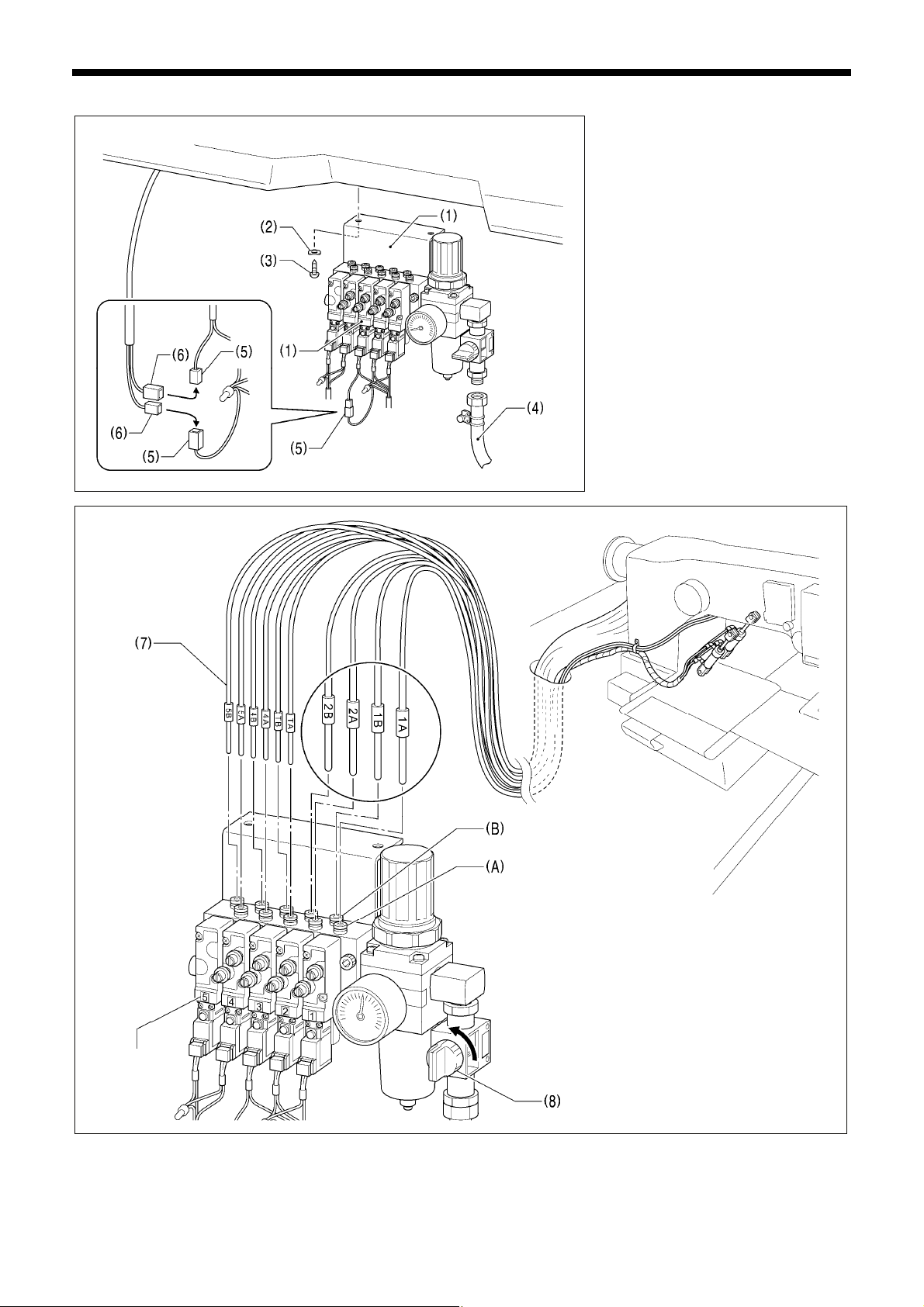
3-7. Installing the pneumatic unit
3. INSTALLATION
1. Install the pneumatic unit underneath
the work table.
(1) Solenoid valve assembly
(2) Washers [2 pcs.]
(3) Wood screws [2 pcs.]
(4) Rubber hose
NOTE:
Make sure that the pneumatic unit
does not touch the control box or the
work table leg.
2. Disconnect the connector (5) of the
valve harness.
3. Connect the connector (6) of the
thread wiper switch to the connector
(5).
4644M
Valve nos.
fter installing the pneumatic unit,
adjust the air pressure. (Refer to
"10-17. Adjusting the air pressure".)
4645M
4. Connect each of the air tubes (7) to the valves so that all of the numbers match respectively. (Connect the air tube marked with a
T to valve 3.)
The air tubes (7) marked with an A connect to the front valve connections (A), and those marked with B connect to the rear
connections (B).
5. Open the air cock (8).
BAS-300G-484, BAS-300G-484 SF
10
3. INSTALLATION
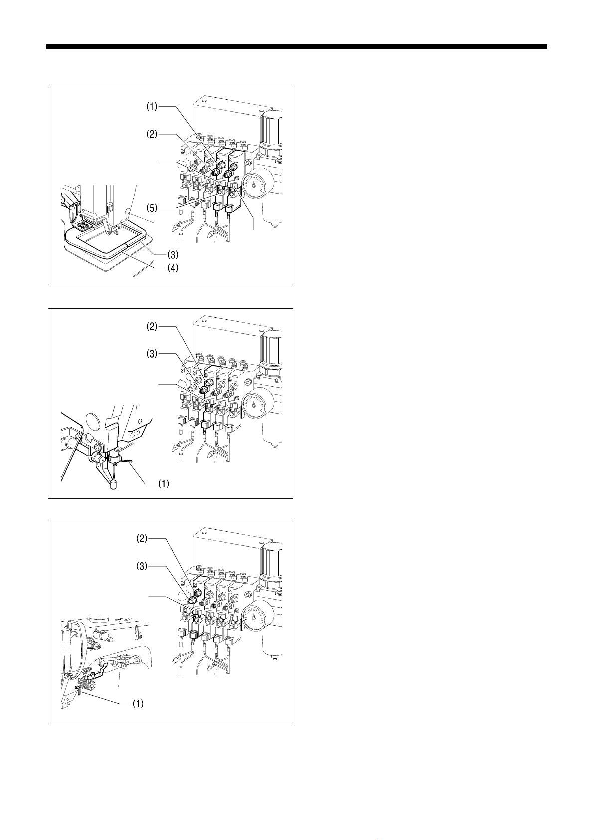
3-8. Adjusting the speed controller
<Adjusting the lifting and lowering speeds for the work clamp>
Val ve 2
You can adjust the lifting and lowering speeds for the work
clamps using the knobs (1) and (2) on valves 1 and 2.
Valve 1 adjusts the right work clamp (3), and valve 2 adjusts
the left work clamp (4).
The knobs (1) and (2) should be adjusted so that the left and
right work clamps operate at the same speed.
• When the upper knob (1) is tightened, the lifting speed
becomes slower. When it is loosened, the lifting speed
becomes faster.
• When the lower knob (2) is tightened, the lowering speed
becomes slower. When it is loosened, the lowering speed
becomes faster.
Val ve 1
<Adjusting the thread wiper operating speed>
Val ve 3
<Adjusting the thread take-up lever operating speed>
4646M
4647M
You can operate the work clamp when the power is turned off
by pressing the manual buttons (5).
Valve 3 is used for adjusting the operating speed of the thread
wiper (1).
To use, fully tighten both the upper and lower knobs (2) and (3),
and then loosen them both by 6 turns.
NOTE:
If the knobs (2) and (3) are tightened more than the settings
mentioned above, upper thread wiping may not be carried
out correctly.
Valve 4 is used for adjusting the operating speed of the thread
take-up lever (1).
To use, fully tighten both the upper and lower knobs (2) and (3),
and then loosen them both by 6 turns.
11
NOTE:
If the knobs (2) and (3) are tightened more than the settings
Val ve 4
mentioned above, the upper thread trailing length may not
be maintained correctly.
4648M
BAS-300G-484, BAS-300G-484 SF

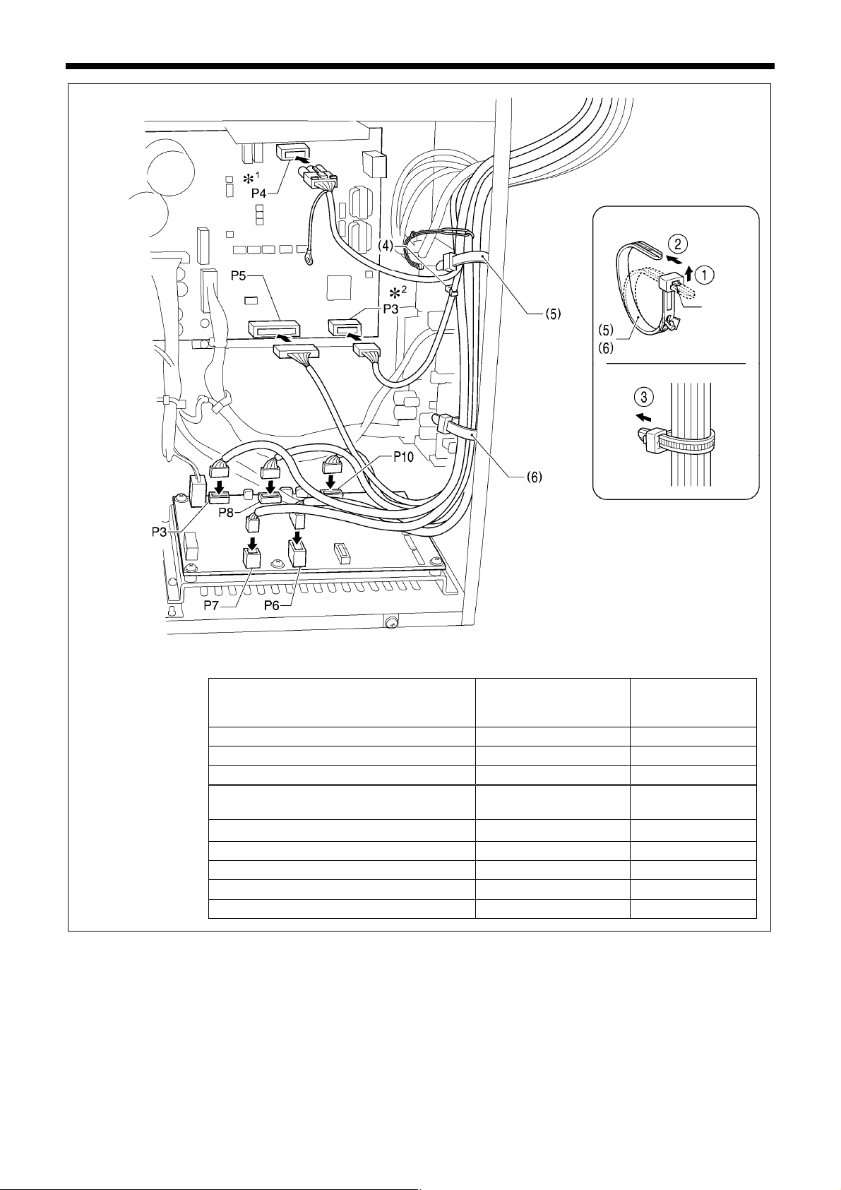
3-9. Connecting the cords
<Main P.C. board>
3. INSTALLATION
1. Gently tilt back the machine head.
2. Pass the cord bundle through the hole
in the work table.
3. Loosen the two screws (1), and then
open the cord presser plate (2) in the
direction of the arrow and pass the
cord bundle through the opening
together with the following cords.
• Two-pedal foot switch (3)
• Operation panel (Do not pass the
ground wires through the hole.)
• Solenoid valve assembly
4. Securely connect the connectors as
indicated in the table below.
4649M
NOTE:
• Check that the connector is facing the correct
way, and then insert it firmly until it locks into
place.
• Secure the cables with cable ties and cord
clamps, while being careful not to pull on the
connector.
*1:
Be sure to make the ground connection.
(Refer to "3-10. Connecting the ground wire".)
*2:
Only applicable to -484 SF specifications.
X pulse motor encoder 5-pin white P20 (X-ENC) (3)
Y pulse motor encoder 5-pin blue P4 (Y-ENC) (3)
Work clamp pulse motor encoder 5-pin black
Foot switch 10-pin P6 (FOOT) (3)
Operation panel 8-pin P1 (PANEL) (3)
Machine head switch 3-pin P9 (HEAD-SW) (4)
Home position sensor assembly 12-pin P8 (SENSOR1) (4)
STOP switch 6-pin P13 (HEAD) (4)
Valve harness 12-pin P12 (AIR1) (4)
Valve harness 5-pin P26 (AIR3) (4)
Programmer relay harness 8-pin P7 (PRG) (3)
Solenoid selection harness 4-pin P3 (CUTTER) -
4650M
Thread trimming cylinder sensor harness 16-pin P23 (EX-IN1) (4)
Connector
Lock the cord
clamp securely.
Connection location on
main P.C. board
*
2
P5 (P-ENC) (3)
Cord clamp
(Continued on next page)
BAS-300G-484, BAS-300G-484 SF
12
3. INSTALLATION
<Power supply motor P.C. board>
<PMD P.C. board>
Machine head memory 7-pin P3 (HEAD-M) (4)
Upper shaft motor 3-pin P4 (UVW) (5)
Synchronizer 14-pin P5 (SYNC) (5), (6)
Work clamp pulse motor 4-pin black
Thread trimmer solenoid 6-pin P6 (SOL1) (5), (6)
Tension release solenoid 4-pin P7 (SOL2) (5), (6)
Y pulse motor 4-pin blue P8 (YPM) (5), (6)
4651M
X pulse motor 4-pin white P10 (XPM) (5), (6)
Connector
Connector
<Removing>
Press
the tab.
<Securing>
NOTE:
Route the X, Y and work clamp pulse motor
harnesses so that they do not touch the
PMD P.C.
*1:
Be sure to make the ground connection.
(Refer to "3-10. Connecting the ground
wire".)
*2:
Only applicable to -484 SF specifications.
Connection location on
power supply motor P.C.
Cord clamp/cable tie
board
Connection location on
PMD P.C. board
*
2
P3 (PPM) (5), (6)
Cable tie
(Continued on next page)
13
BAS-300G-484, BAS-300G-484 SF
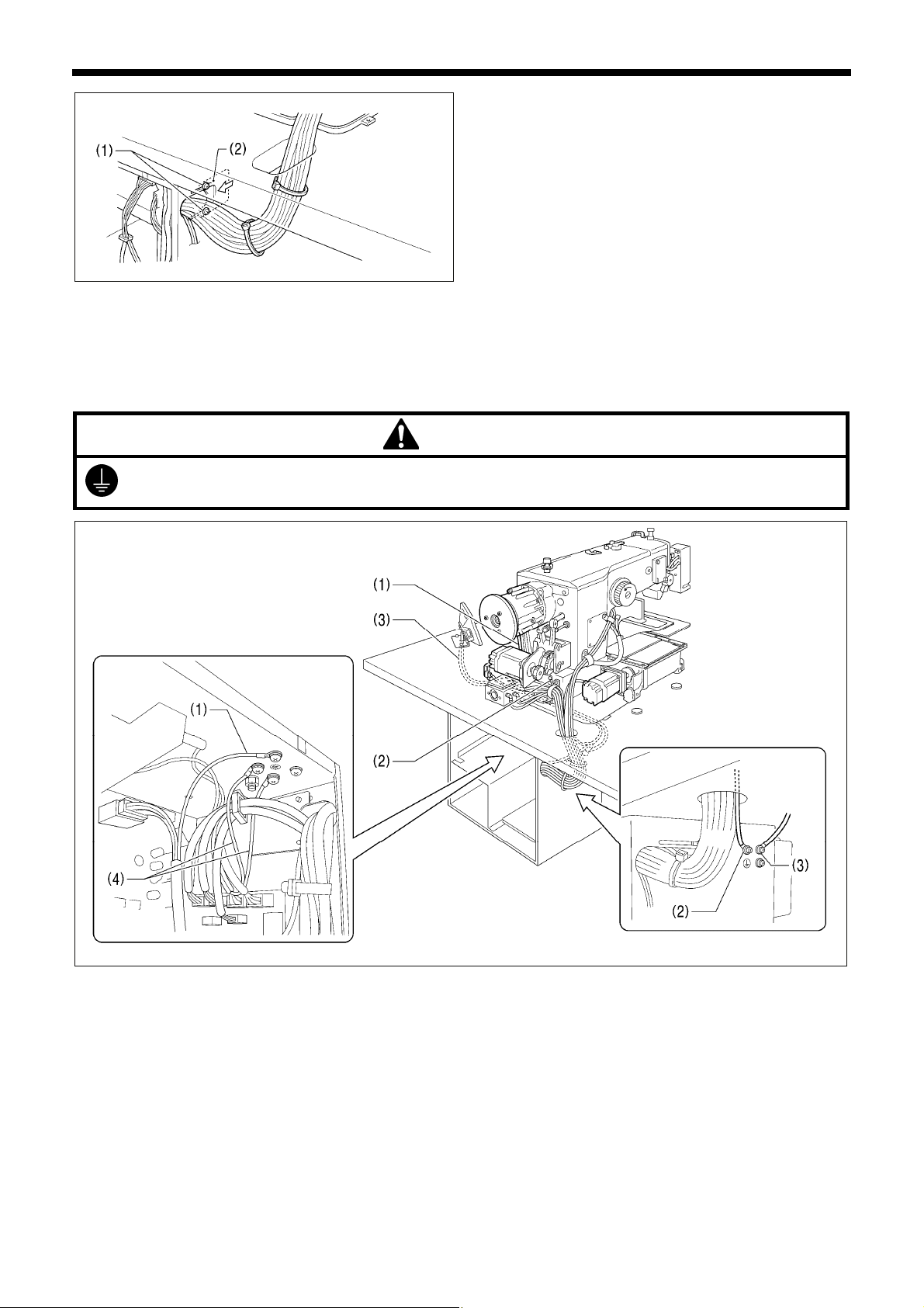
3-10. Connecting the ground wire
CAUTION
Be sure to connect the ground. If the ground connection is not secure, you run a high risk of receiving a serious electric
shock, and problems with correct operation may also occur.
3. INSTALLATION
5. Close the cord presser plate (2) in the direction of the left
arrow, and secure it by tightening the two screws (1).
NOTE: Close the cord presser plate (2) securely so that no
foreign objects, insects or small animals can get
inside the control box.
6. Check that the cords do not get pulled, and then gently
return the machine head to its original position.
2149B
(1) Ground wire from upper shaft motor harness
(2) Ground wire from the machine head
(3) Ground wire from operation panel
(4) Ground wires from two-pedal foot switch harnesses (2 wires)
• Tighten the control box cover with the eight screws. Check that the cords are not clamped by the cover at this time.
4652M
NOTE: Make sure that the ground connections are secure in order to ensure safety.
BAS-300G-484, BAS-300G-484 SF
14
3. INSTALLATION
3-11. Connecting the power cord
<Single-phase
specifications>
<Three-phase
specifications>
Green and yellow wire
(ground wire)
Green and yellow wire
(ground wire)
1. Attach an appropriate plug to the
power cord (1). (The green and yellow
wire is the ground wire.)
2. Insert the plug into a
properly-grounded AC power supply.
* The inside of the control box uses
single-phase power.
NOTE:
Do not use an extension cord. If this is
not observed, it may cause problems
with correct operation.
5239Q
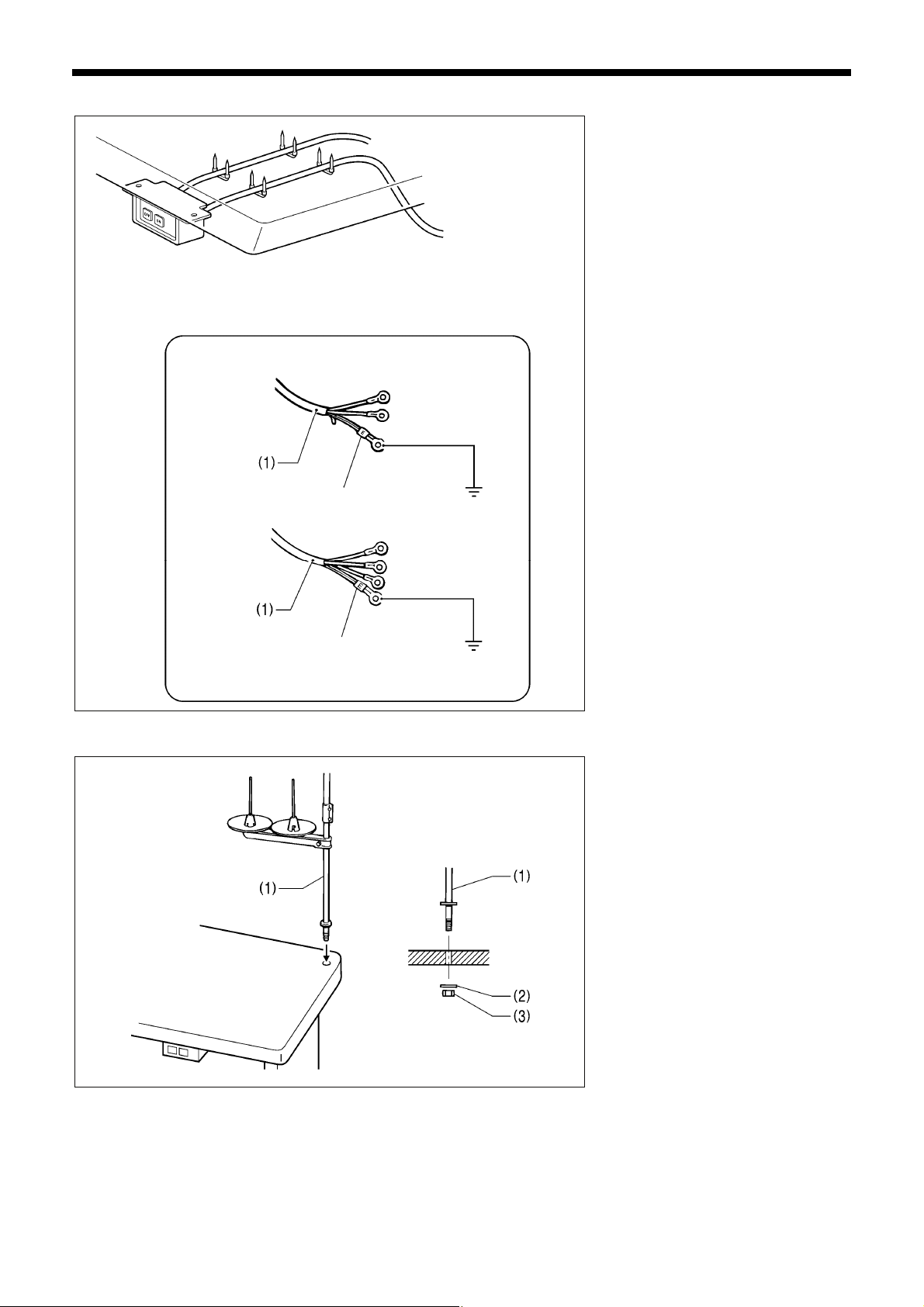
3-12. Installing the cotton stand
(1) Cotton stand
NOTE:
Fit the washer (2), and then securely
tighten the nut (3) so that the cotton
stand does not move.
2974B
15
BAS-300G-484, BAS-300G-484 SF
3-13. Installing the eye guard
Attach all safety devices before using the sewing machine.
If the machine is used without these devices attached, injury may result.
3. INSTALLATION
CAUTION
(1) Screw (loosen)
(2) Eye guard (tilt forward)
(3) Eye guard assembly
(4) Plain washers [2 pcs.]
(5) Screws [2 pcs.]
After installing the eye guard assembly
(3), return the eye guard (2) to its original
angle, and then tighten the screw (1) to
secure it in place.
2152B
BAS-300G-484, BAS-300G-484 SF
16
3. INSTALLATION
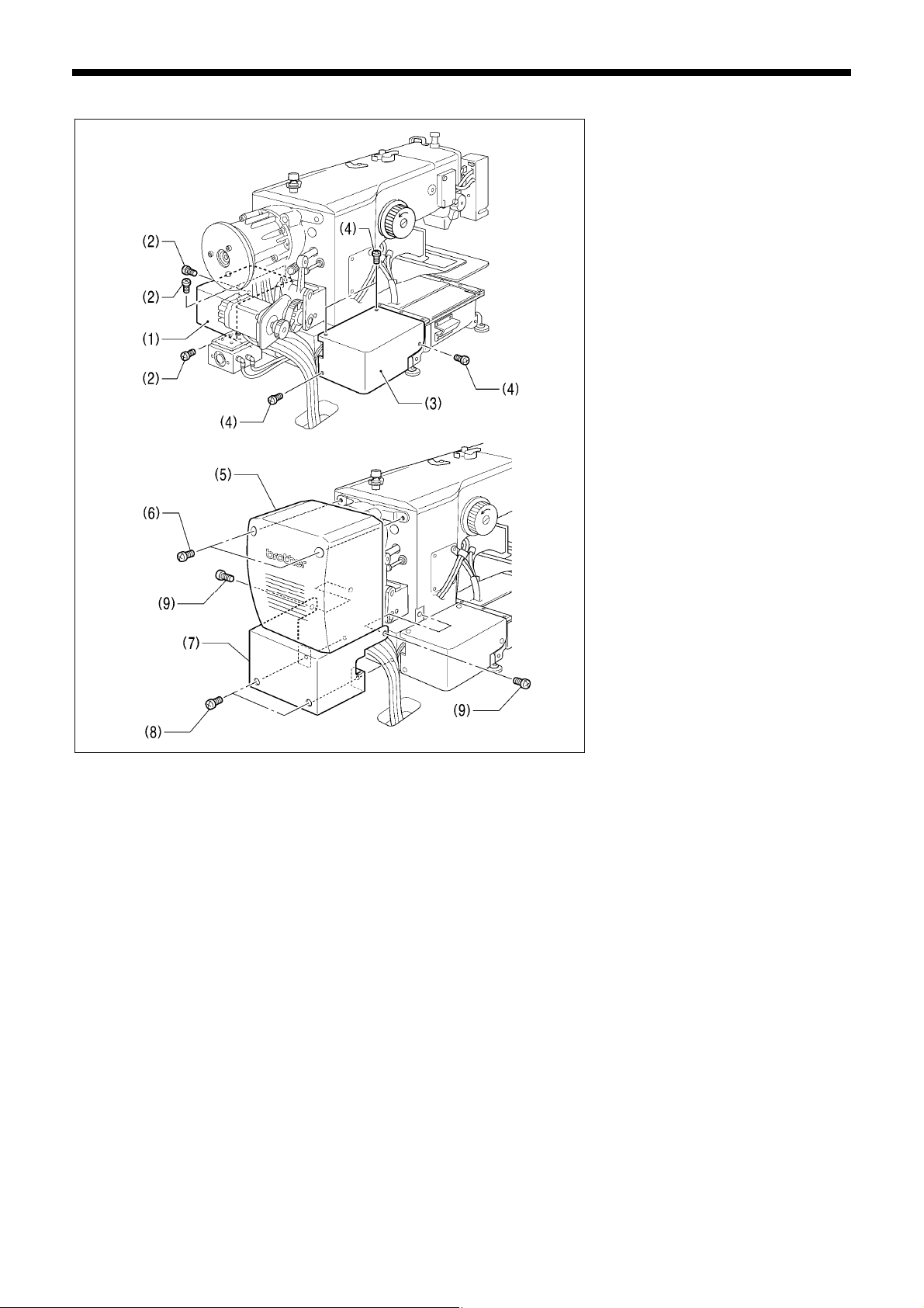
3-14. Installing the motor cover
4653M
4654M
(1) Motor cover R
(2) Screws [4 pcs.]
(3) Motor cover L
(4) Screws [4 pcs.]
(5) Motor cover
(6) Screws [2 pcs.]
(7) Solenoid cover
(8) Screws [2 pcs.]
(9) Screws [2 pcs.]
NOTE:
Be careful not to clamp the cords when
installing the motor cover and the
solenoid cover.
17
BAS-300G-484, BAS-300G-484 SF
3. INSTALLATION
3-15. Lubrication
CAUTION
Do not connect the power cord until lubrication is complete.
If the foot switch is depressed by mistake, the sewing machine might start operating and injury could result.
Be sure to wear protective goggles and gloves when handling the lubricating oil and grease, so that they do not get into
your eyes or onto your skin. If the oil and grease get into your eyes or onto your skin, inflammation can result.
Furthermore, do not drink or eat the lubricating oil or grease. They may cause diarrhea or vomiting.
Keep the oil out of the reach of children.
The sewing machine should always be lubricated and the oil supply replenished before it is used for the first time, and also after
long periods of non-use.
Use only the lubricating oil <JX Nippon Oil & Energy Corporation Sewing Lube 10N; VG10> specified by Brother.
* If this type of lubricating oil is difficult to obtain, the recommended oil to use is <Exxon Mobil Essotex SM10; VG10>.
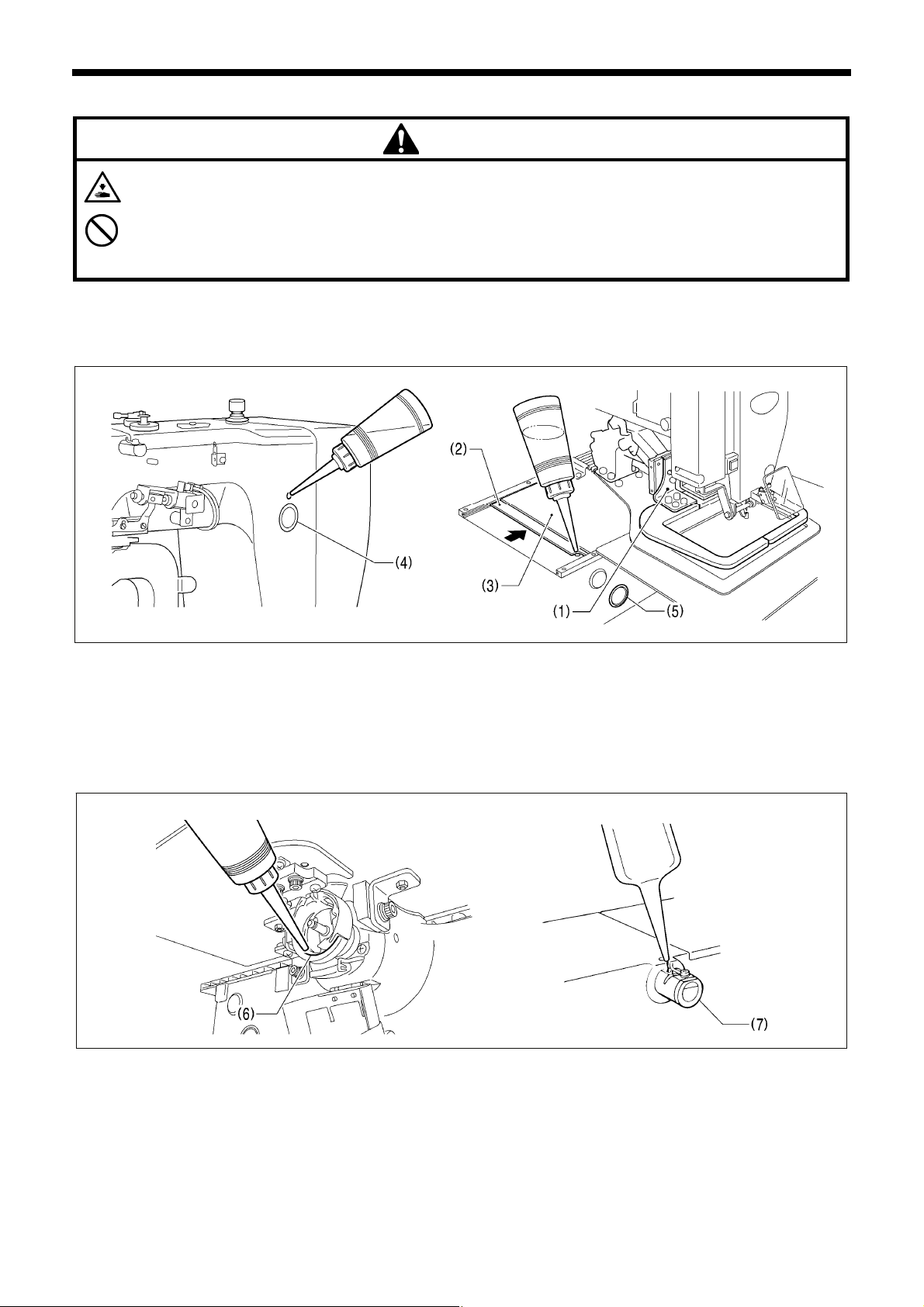
1. Fill the arm-side oil tank with oil.
2. Move the work clamp arm (1) as far as it will go to the right when looking from the front of the sewing machine, and then slide the
outer cover L (2) into the inner cover L (3) so that the lubrication hole in the bed is visible. Pour oil into the bed side oil tank
through this hole.
NOTE:
Be sure to fill the machine with oil when the oil level drops below the one-third level in the oil sight glasses (4) or (5). If the oil level
drops below the one-third level in the oil sight glasses (4) or (5), there is the danger that the sewing machine may seize during
operation.
4657M 4658M
3. Remove the bobbin case and add 2-3 drops of oil to the sliding parts (6) of the outer rotary hook and inner hook.
4. If using the needle cooler (7), fill it with silicon oil (100 mm
2
/s). (Refer to “4-2. Threading the upper thread”.)
4656M4655M
BAS-300G-484, BAS-300G-484 SF
18
 Loading...