

Brother LT2 B832 Parts Book
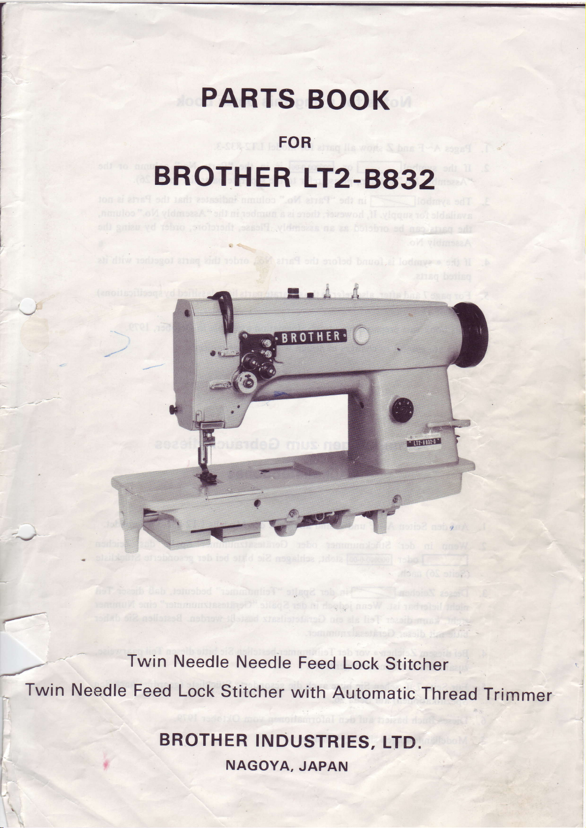
PARTS
BOOK
FOR
BROTHER
LT2-8832
/
f
I
t.
I
I
I
I
I
I
Twin
Twin
Needle
Feed
Needle
Lock
ROTH:IJ}?:;IIIES'
Needle
Stitcher
with
Feed
Lock
Automatic
Stitcher
Thread
LTD
Trimmer
Notes
for using
this
parts
book
l. Pages A-F
2. If
3.
4.
5.
6.
7. Parts
the symboll-l
"Assembly
The
symboll-- in
available
the
Assembly No.
If the * symbol is
paired
For
on
This
for
parts
parts.
page
7
page 26.
book was
are subject to changes
and Z show
No."
column,
supply.
can be ordered
and after, also refer
prepared
If,
however,
found
all
or
please
the
as an assembly.
before the Parts
based
parts
for
model LT2-832-3.
1000000fi01
refer
to the
"Parts
to the
in
No."
there
is
separate
on information
design
without
is
in the "parts
separate parts
column
a number
Please,
No.,
order
parts
available
prior
No."
column
(page
list
indicates
in the "Assembly
therefore,
(classified
list
notice.
that
order
parts
this
in
October,1979.
the Parts
together
by
or the
26).
is
not
No."
column,
by using
specifications)
with
the
its
Anmerkungen
Stticklistebuches
l.
Auf den Seiten A-F
2. Wenn in
(Seite
3. Dieses
nicht
steht,
mit
bitte
Bei
4.
5.
6.
diesem
zusammen mit seinem Gegensttick
Fiir Seite 7 ff. sehen
Spezifikationen)
Dieses Buch
der
26)
nach.
Zeichen
lieferbar ist. Wenn
kann
dieser
dieser
Gerdtesatznummer.
Zeichen
basiert auf den
undZ sind
Sttcknummer
jedoch
Teil
als ein Geriiteteilsatz
*
vor der Teilnummer
Sie
bitte auch die
auf Seite
zum
alle
oder Geriitesatznummer
in
26.
Informationen
Gebrauch
Teile
des
der Spalte
bestellen
gesonderte
vom
bestellt
dieses
Modells
"Gerd.tesatznummer"
Sie
Oktober 1979.
LT2-832-3
Spalte
werden. Bestellen
bitte diesen Teil
Stiickliste
(geordnet
abgebildet.
das Zeichen
eine Nummer
Sie
daher
paarweise,
nach
den
5 Modelliinderungensindvorbehalten.
Notes
l'utilisation
sur
de
ce
d6tach6es
manuel
de
pibces
l.
LT2-8832-3.
2. Sile symbole
dans
Le symbole
3.
fournie.
pibce
toute
4.
Si, devant
pibce
Pour la
5.
(class6es
Ce manuel
6.
Les
7 .
de
la colonne
Si,
dans
peut
Otre
commande,
le
appari6e.
pageT
selon
a 6tbfait d'aprbs
pibces
peuvent
pages
Les
Notas
F
A
i
I-l
"No
la colonne
command6e
no
de
et les suivantes, veuillez aussi vous r6f6rer
les sp6cifications),
page
et le
de
veuillez
pibce,
Otre sujettes ir des
para
Z
montrent toutes les
ou
[6666d6]T6'l
ensemble",
jeu
"No
comme faisant
sp6cifier le no du
le
il y a
symbole
page
les renseignements valables au mois
usar este
pibces
estpr6sentdanslacolonne
se r6f6rer
pces",
de
*,
26.
modifications
la liste
ir
y
il
a un num6ro
partie
d'un
jeu
veuillez commander
de
pibces.
Libro
de
jeu
ir
sans
de
(vue
6clat6e)
"Node
pi6ces
annexe
nomenclature,
de
pibces.
de
cette
la liste
prbavis.
de
de Octobre
Piezas
du modble
pibce"
(page26).
Donc,
pibce
pibces
ou
la
pour
avec sa
annexe
1979.
pfginas
Las
I
.
2. De haber el
Pieza" o en
(p6gina 26).
El simbolo
3.
quiere
en
-
yor
4. Si,
dicha
5.
(clasificada
6.
de
7. Las
decir
la columna del
tanto, ser6
lo
del
antes
pieza
Parala
Este libro
p6gina 7 y las
ha sido compilado
1979.
piezas
quedan
y
F
desde A a
simbolof-lo el
"Ntmero
la
del
que no
junto
segrin
se dispone de
"Ntmero
mejor hacer el
ntmero de
con
las especificaciones) de
sujetas a cambios de disefro
la Z muestran todas las
de Juego", habr6
de Juego",
pedido
pieza,
una
la otra con
que
le
siguen,
basfndose en los datos
lTooooolidl
pieza
dicha
podr6
se
recurriendo
se encuentra el
que
la
habr6
va
que
la
piezas
en
que
sola. Cuando,
ordenar la
la
misma.
ver tambi6n la lista
p|gina
sin
del modelo
la
columna
ver la lista
empero, hay un nrimero
pieza
nfmero
al
simbolo,
26.
que
de
aviso
se
previo.
*,
LT2-8832-3.
"Nfmero
del
piezas
de
con todo
deljuego
habr6
de
disponia en octubre
respectivo.
que
piezas
separada
separada
de
eljuego.
ordenar
l'
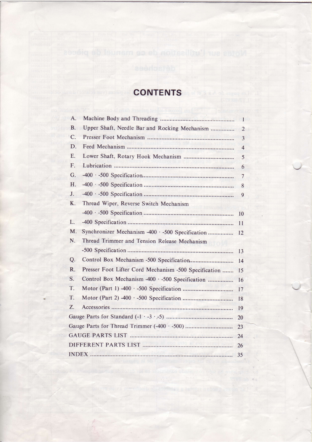
A.
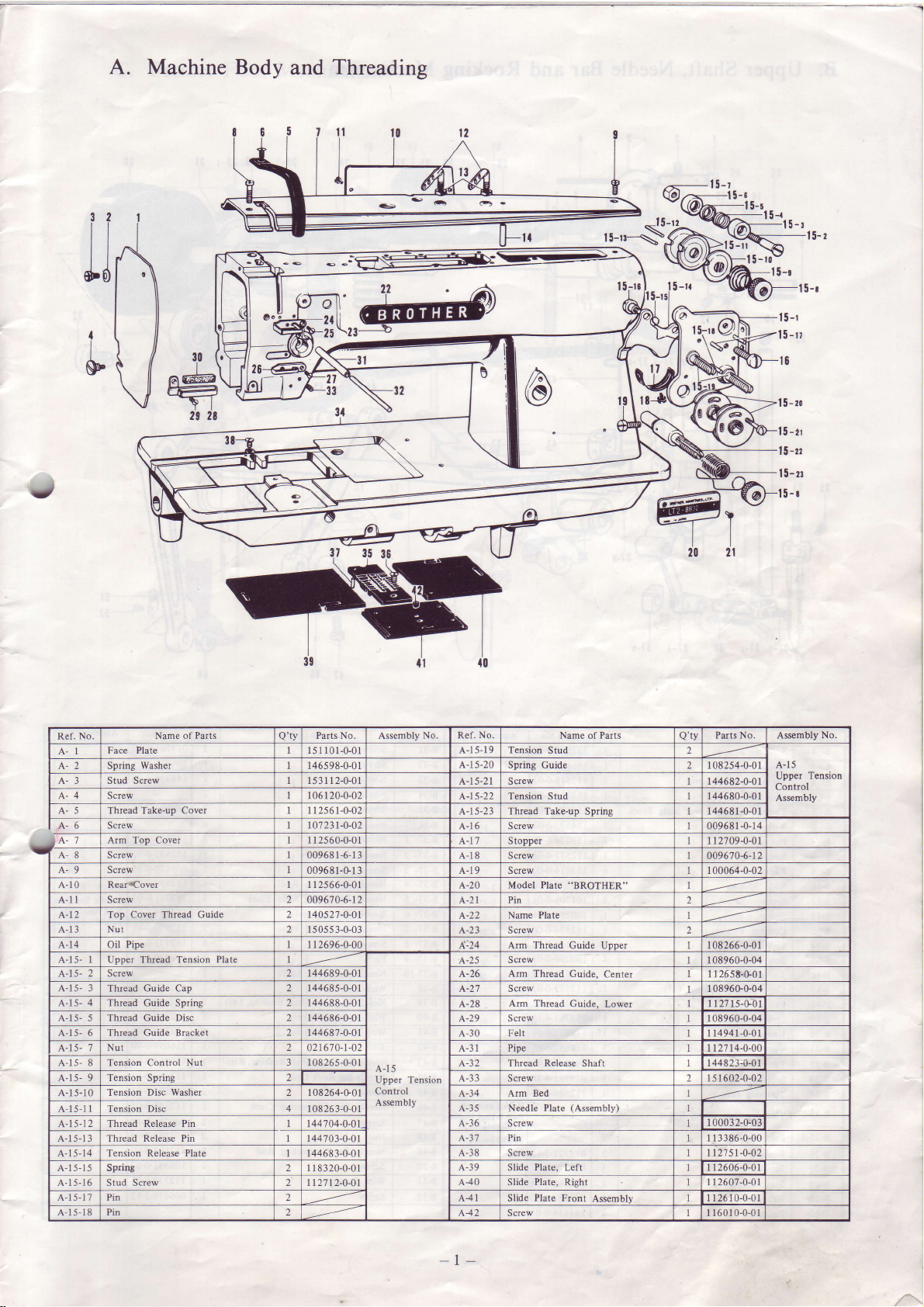
Machine
B.
Upper Shaft,
Presser
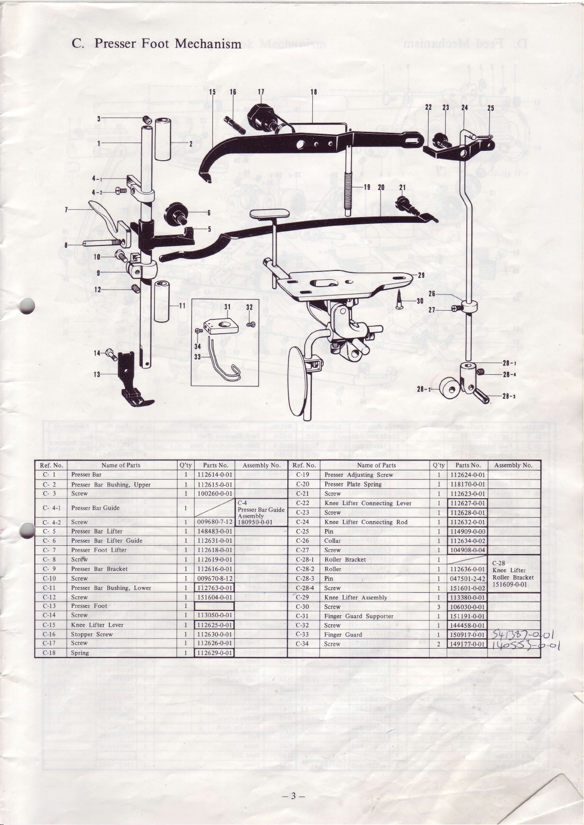
C.
D.
Feed Mechanism
E.
Lower
F.
Lubrication
-400 ' -500
G.
-400 ' -500
H.
-400 ' -500
J.
K.
Thread Wiper,
-400
-400
L.
M.
Synchronizer
N. Thread Trimmer
-500
Control Box
a.
Presser Foot Lifter
R.
S. Control Box
T. Motor
T. Motor
Z. Accessories
Gauge
Gauge
GAUGE
DIFFERENT
INDEX
Parts for Standard
Parts for Thread Trimmer
Body
Needle Bar
Foot
Mechanism
Shaft, Rotary
Specification.......
Specification
Specification
Reverse
.
-500
Specification
Specification
Mechanism
Specification
Mechanism
Mechanism
(Part
(Part
PARTS LIST
-400 . -500
l)
2) 400
PARTS
CONTENTS
Threading
and
and Rocking
Hook Mechanism
Switch Mechanism
.
400
and Tension
Cord Mechanism
.
-500
(-l
........
LIST ........
Release
-500
Specification...............
.
-400
Specification
Specification
'
'.-5)
-3
(-400
Mechanism
-500
Specification................
Mechanism
-500
Specification
-500
Specification
..........
.
-500).........
l0
I
12
13
14
....... l5
16
t7
18
19
20
23
24
26
35
I
2
3
4
5
6
8
9
I
Machine
A.
Body
Threading
and
32
t 1l
t
I
-
rs-rr$f
-t 5-rI
l5-rr
t5-to
s0
A
15-t
til
{
30
&
V
F
#
a@
29 28
1
21
33
31
J
l
2t
t5-u
t6
1
5-to
5-tr
15-Ir
l5-n
5-r
No.
Ref.
A-l
A-3 Stud Screw t531 12-0-01
A,- 4 Screw L 06 1 20-0-02
A-5 Thread Take-up Covel t12s61-0-02
A-6 Screw t07211-0-02
A-8 Screw 00968 I
A-9 Screw
A-10 RearrCover L 1 2566-0-0
A-l t
A-l Top
A-13 Nut
A-14 Oil Pipe t 1 2696-0-00
A-15-
A-t 5- 2 Screw t44689-0-0 1
A-15- 3 Thread Guide Cap 2
A-15A-15- 5
A-15- 6 Thread
A-15- 7
A-15- 8 Tension Control
A-15A-15-10 Tension
A-15-1 ITension
A-t
A-15-13 Thread Release Pin I 44703-0-0
A-15-14 Tension Release
A-15-15 Spring 2 l
A-15-16 Stud Screw 2 1127 12-0-01
A-15-17 Pin 2
A-15-18 Pin 2
Face Plate L5 I 101-0-01
Spring
Arm
Screw 009670-6-12
I Upper Thread Tension
4 Thread Guide Spring 2 t44688.0-0
Thread Guide Disc 2 44686.0-0
Nut 2
9 Tension Sprine 2
5.1 2Thread
Name of Parts
Washer
Top Cover
Cover Thread Guide 405 27-0-0
Plate
Guide Bracket 2 4468 7-0-0
Nut 3 t
Disc Washer
Disc 4 108263-0-01
Release Pin
Plate
Parts No Assembly
Q'ty
t46598-0-0 I
L I
2560-0-0 1
-6-1
009681-G1
5055 3-0-0
r44685-0-01
021670-l-02
-0"0
265
08
2 I 08264-G0l
144704-0-01
1 4468 3-0-0 l
I 8320-0-01
3
3
1
I
I
I
I
I
1
No. Ref. No, Name
A-15
Upper Tension
Control
Assembly
Parts
A-15-19 Tension
A-1 5-20
A-15-21 S
A,-15-22 Tension Stud 144680-0-01
A-20
A.2I Pin
A-22
A-23 Screw
^:24
A-25
A,-26
A,-27 Screw 0896GG04
A-28
A-29
A-30
A-31
A-32 Thread Release Shaft
A-3 3 Screw l
A.-34 Arm Bed
A-35 Needle
A-36 Screw
A-31 Pin 3 386-0-00
A-38 Screw
A-39
A-40 Slide Plate, Right 2607-0-0 l
441 Slide
A,42
Spring Guide
crew
5-23 Thread Take-up Spring 14468 1-0-01
6
Screw 00968 I
7 Stopper 1 1 2709-0-01
8 Screw 009670-6-12
9 Screw 100064-0-02
Model Plate
Name Plate
Arm Thread
Screw
Arm
Thread Guide.
Arm Thread
Screw
Felt 4941-0-01
Pipe
Plate,
Slide
Plate
Screw 60 I 0-0-0 1
of
Stud
"BROTHER"
Guide Upper 08266-0-01
Center 26s6+01
Guide. Lower 2715-G01
(Assembly)
Plate
Lefl 2606-0-0 t
Front
Assembly
Puts No Assembly No.
Q'ty
1 08 254-0-01
r44682-0-01
-0-l
08960-0-04
08960-0-04
27 l4-0-01
44823-0-0
5 I 602-0-02
r00032-G03
| 127 51-0-02
26 I 0-0-0 I
4
I
A-15
Upper Tension
Control
Assembly
-l -
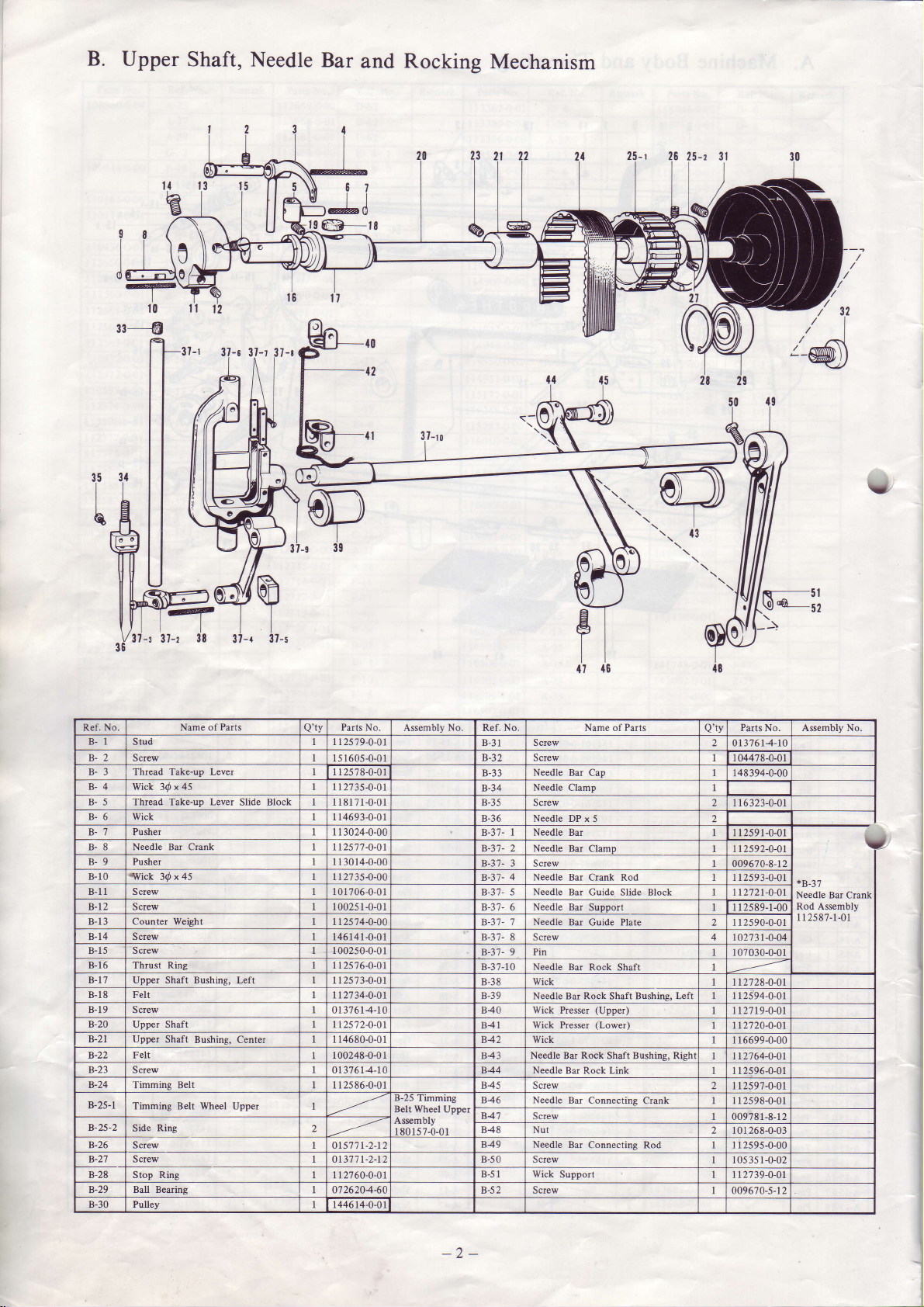
B.
Upper
I
Shaft,
Needle
Bar
and Rocking
Mechanism
20
I
t0
-s
ll-
s
37-r 37-a
10
12
35
I
b
Ref. No. Name of
B-1
Stud 25
B-2 Screw
Thread Take-up
B-4
Wick 3@ x
B-5 Thread Take-up Lever
B-6 Wick
Pusher
B-'l
B-8 Needle Ba Crank 257'7
B-9 Pusher l0l4-0-00
-tVick
B-10
B-11 Screw I
B.T2
B-13 Counter Weight
B-14
B-15 Screw 100250-0-0i
B-16
B-1',7 Upper Shaft Bushing, Left
B-18 Felt
B-19
B-20 Upper Shaft
B-21
B-22
B-23 Screw
B-24 Timming Belt
B-25-1
B-25-2
B-26 S crew
B-21 S crew
B-28 Stop Ring
B-29 Ball Bearing
B-30 Pulley
30 x
Screw
Screw 146 14 I
Ring
Thrust
Screw
Upper Shaft
Falt
Timming Belt Wheel
Ring
Side
Parts
Lever
45
Slide
45
Bushing, Center
Upper
Block
0P
-g
39
Parts No.
Q'ty
79-0.0
1605-0-0
25
78-0-0
27 35-0-0
81 71-0-0 B-35
4693-0-0
3024-0-00
-0-0
27
35-0-00
0 1 ?06-0-01 B-37- 5
00251-0-0
12574-0-00
-0-01
2s'76-0-0
2573-0-0
2',7 34-0-0
0 3761,4-10 840
2s'12-0-0
4680-0-0
100248-0-0 1
0l 37614-10 844 Needle
I 12586-0-01 845 Screw
01577 1-2-r2
o1,3'.771-2-1 B-50 Screw
I 1 2760-0-01
0'726204-60
446 14-0-01
37-ro
Assembly
B-25 Timming
Belt Wheel
Assmbly
I 80157-0-01
Upper
No
No.
Ref
B-31 Screw
B-32 Screw
B-33
B-34
B-36 Needle
B-3?-
B-37-
B-31- 3 Screw
B-3'7-
B-3'7- 6
B-3'7-
B-37- 8 Screw
B-3',7- 9 Pin
B-37-1 0 Needle Bar
B-38
B-39
84t
842 Wick
843
846 Needle
84',7 Screw
848 Nut
849 Needle
B-51 Wick
2
B-5
Parts
Name of
Needle Bar
Needle
Screw
l Needle
2
Needle Bar Clamp
4 Needle Bar
Needle
Needle Bar
',l
Needle
Wick
Needle Bu Rock Shaft Bushing, Left
Wick
Wick Presser
Needle
Screw
Cap I 48
Clamp
DP x 5
Bar
Crank Rod 2591-0-01
Bar Guide
Bar Guide Plate 25
Presser
Bu
Bar Rock Link
Bar Connecting Crank
Bar Connecting
Support L 1 27
Slide Block 21 21-0-01
Supporl 2s89-1-00
Rock Shaft
(Upper)
(Lower)
Rock
Shaft Bushing,
n-51
\Q)Lsz
-\
Puts No Assembly No.
Q'tv
0137614-10
l
04478-0-01
394-0-00
116323-0-01
II259i-0-01
112s92-0-01
009670-8-l 2
90-0-01
t02't3l-o-04
t 07030-0-01
2728-0-01
25
94-0-01
27 1 9-0-01
2720-0-01
Righr
Rod t 1 2595-0-00
6699-0-00
2764-0-01
2596-0-0 1
2597-0-01
2598-0-0 1
009?8 1-8-1 2
t01 268-0-03
-0-02
t 05 3s 1
39-0-01
00967
0-5-12
v'
/32
a'6
*B-3'.1
Needle Bar Crank
Rod Assembly
-01
1 1 2s 8?-1
v.
-2-
a
C.
Presser
Foot Mechanism
Guide
Parts
Parts No. Assembly No Ref. No. Name of Parts
Q'tv
112614-0-01 c-19 Presser
C4
009680-7- I 2
Presser Bar
Assembly
l 809s0-0-01
Guide
Presser Plate
c-20
Scrcw
c-22 Knee Lifter
c-23
Screw I I 2628-0-01
Knee
c-24
Lifter Connectins Rod t I 2632-0-01
Adjusting Screw 1126241)-01
No Nam€ of
Ref.
Presser Bar
Presser
Screw 100260-0-01
c-3
c- 4-1 Presser Bar
Screw
c- 4-2
Bar Bushing, Upper 1 12615-0-01
c-5 Presser Bar Lifter 8483-0-0 Pin
Presser
c-6
Bar Lifter Guide 26 1-0-0 c-26 Collar
Foot Lifter
Presser
26 8-0-0 c-27 Screw r04908{-04
c-8 Scr& 26 9-0-0 c-28-1 Roller Bracket
Presser
c-9
c-10
c-11
c-12 Screw
3
c-1
c-14
c-16 Stopper Screw 2630-0-0
c-17
Bu Bracket 26
Screw
Presser Bd Bushing, Lower
Presser
Fool
Screw
Knee Lifter Lever
Screw 2626-0-0
6-0-0 c-28-2
009670-8-1 2 c-28-3 Pin
tt2763-0-01 c-284 Screw
I 5 I 604-0-01 c-29 Knee Lifter
3050-0-0
2625-O-O
Roller
c-t0 Screw I 06030-0-01
c-31
Fineer Guard SuDDorter 1s1191-0-01
Screw
Finger
c-34 Screw
Guard
c-18 Spring 2629-0-O
Pilts
Q'tv
Spring I 18170{-01
No. Assembly No.
112623-0-01
Connecting Lever tt2627
-0-01
r
14909-0-0(
112634-0-02
t 12636-0-01
047
501-242
15 1
601-0-02
Assembly
1 3380-0-01
144458-0-01
I s09 1 7-0-0 1 >vr fb t-c
t49t'77-0-01
c-28
Knee Lifter
Roller Brackel
I 5 I 609-0-01
ta(.4 \-
OI
'c,
i
-3
-
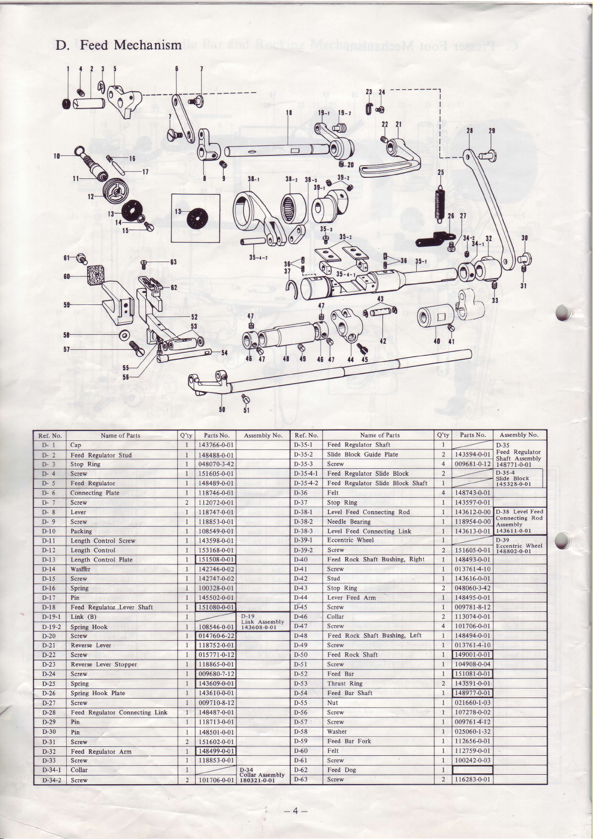
D.
Feed
Mechanis
ritii
isv,
N1,,
%
lg--03
SM
5t
6
ll
I
6v
Nd
il$n-
N
\r,
I
p.l
?
I
3!-r
N
35-r-t
3l-r
3t
ll
@l
\e
li<
'l
1'
0d
22 2l
$
---t
-----
\
)
Jzs
**
I
L--
I
A
il
F' ?E
I
q(
Puts
Ring
(B)
Hook
Name of
Stud 148488-0-01
Plate
Contol
Shaft 151080-0-01 D45
-Lever
LeYer
Stopper
Link 148487-0-01
No.
Ref-
D. l cap
Feed Reeulator
D-2
Stop
D.3
I>4 Screw 60s-0-0
Feed Reslator
D.5
D.5 Connecting
D-1
Screw
Level
D-8
D-9 Screw 885 3-0-0
D-10 Packing 108549-0-01
D-l1
Length Control Ssew 143598-0-01
D-12 Length
D-I3 Lensth Control Plate
D-14 Waslltr
D-15
Screw
D-16
Spring
D-1',! Pir 145 502-0-01
D-18 Feed Regulats
Link
D-19-1
D-19-2 Spring
Screw
D-20
D-21 Revers Levei I 187s2-0-01 D49
D-22 Screw 0rs7'7 t-0-t2
D-23 Revers
D-24 Screw 009680-7-t 2
Spring 143609-0-01
D-25
D-26 Spring Hook Plate 1436 10-0-01 D-54
D-27 Screw 0097 10-8-12 D-55
D-28 Feed Regulator Connecting
Pin 118713-0-01 D-57 Screw 0097614-12
D-29
D-30
Pin
D-3t
Screw
D-32 Feed Redator Arm
D-33 Screw
D-34-1 Collu
D-34-2 Screw
Parts No. Assembly No. Ref. No.
Q'tv
r43766-0-01 D-35-1
0480't0-342
8489-0-0
8746-0-0
2072-0-0 D-37
8747{.0
1s 3 168-0-01
15 15 08-04 1
t42746-0-O2 D4l S crew 0137614-10
1427474-02 D42 Stud 143616-0-01
100328-0-01 D43 Stop
D-19
108s46-0-01I 43608-O-0 I
1 1
8865-0-01
148501-0-01
I s l 602-0-01
148499{{1
1 1 88s 3-0-01 D-61 Screw too242-0-o3
I
01 706-0-01
D-34 D42
I
80321-O-0 I
D-35-3 Screw 009681
D-36 Fell 148743-0-01
D-39-2
D40
D-51 Screw 104908-0-04
,A-';
(A-e$)
=T$
{0
{l
D-Jt-2
D-354-1 F€ed Reeulator Slide Block
D-354-2 Feed Renlator Slide Block Shafl
D-38-1 Level Feed Comecting Rod 1436124-00
D-38-2 Needle Beding 1 18954-0-00
D-38-3
D-39-1 Eccentdc Wheel
D44 Lever Feed
D46 Collar 2 I I 3074-0-01
D47
D48
D-s0 Feed Rock Shaft 149001-0-01
D-52 Feed Bu 151081-0-01
D-5J Thrust Ring 143591-0-01
D-56
D-58
D-59
D-60
D{3
Feed Reeulator
Slide Block Guide Plate 143594-0-01
StoD Rins
Level Feed Connectins Link 1436r 3-0-01
S
Feed Rock Shaft Bushing,
S crew 009781-8-1 2
Screw
Feed Rock Shaft Bushing,
Screw 01 37614-10
Feed Bar
Nut 021 660-1-03
Screw l0'12784-02
Washer
Feed
Felt
Feed Dog
Screw
Name of Parts
Shaft
crew
Rielt
Ring
Atm
Lefl
Shaft
Bar Fork I I 2656-0-01
Puts No. Assembly
Q',ty
-0-l
143s97-0-01
2 151605-0{1
148493-0-01
2 048060-342
148495{-01
l
0l 706-0-0 1
148494-0-01
r48977-0-Ur
02s060-1-32
1
12759-0-01
I 16283{-01
2
T
"
No
D-35
Feed Regulator
Shaft Assembly
-0-01
148?7 1
n-1<-4 |
sro"k
Sriii
r45328-0-01 |
D-38 Level
Connecting
Assembly
l-0-O1
14361
D-39
Wheel
Eccentric
48E02-0-O1
I
Feed
Rod
3
I
v
-4-
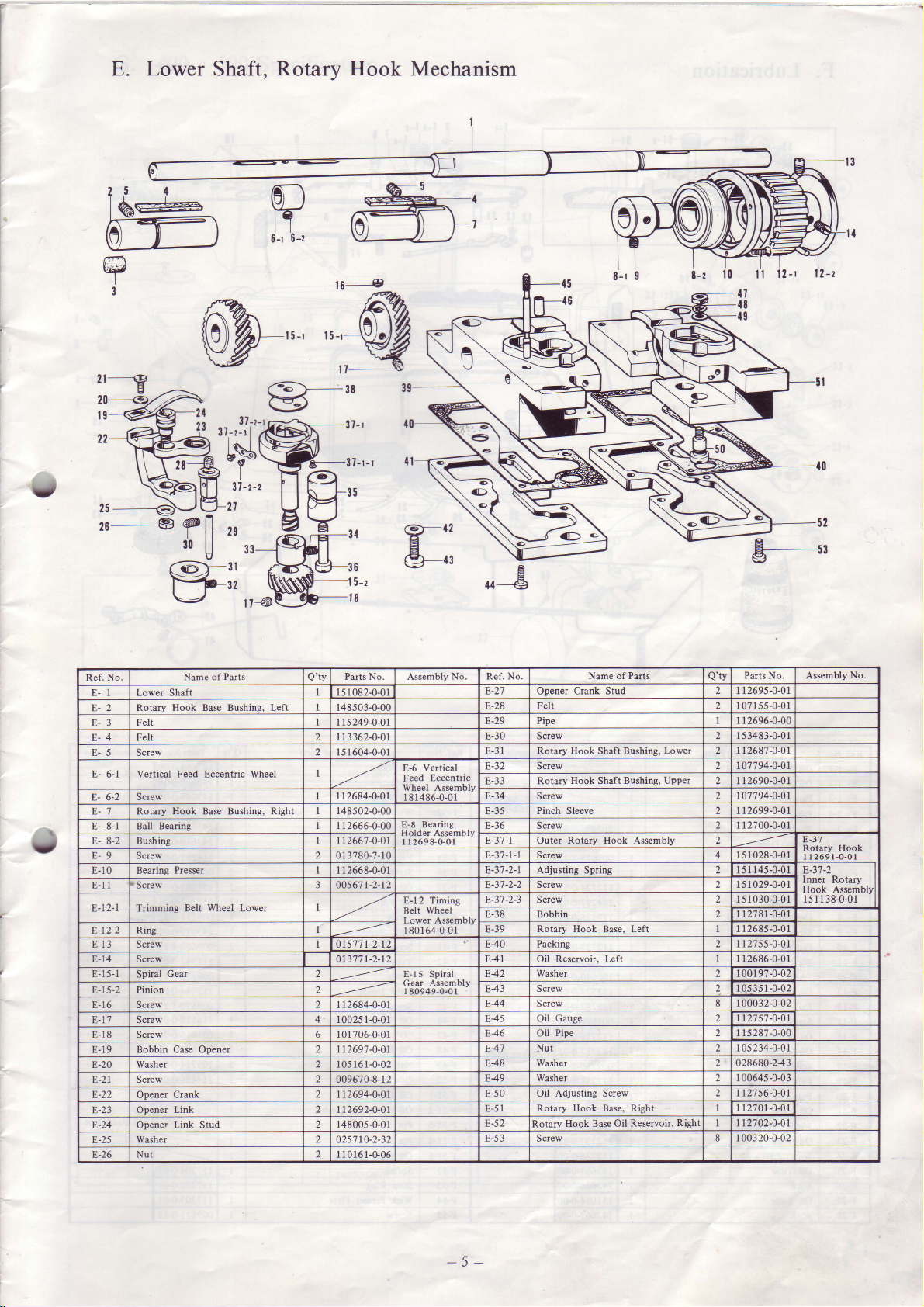
E. Lower Shaft. Rotarv
Hook
Mechanism
U
zF
l%:-
dF
P
3
,t-=
20
t9
22
_-€)
26_
,
W
4t ,r-,1!"-)
ars\
\Pi
oi-) #-'
:r
,T-
31-t-z
27
.ffi==
EL-,
----(9
r6-
,r.rffi
38
37-t
5-r
l8
Name of Parts
Crank Stud 2 1
Shaft Bushing,
Hook Shaft Bushing, Upper
Rotary Hook
Base,
Left 1 1 2686-0-01
Pipe 2 I 15287-0-00
Base Oil
Hook
Lower 2 I I
Assembly
Left t 1 I 2685-0-01
Reservoir, Right tt2'102-0-01
Eccentdc
Assembly
Wheel
Asrembly
64-0-01
Assembly
r
80949-Or0 I
No. Ref. No.
E-2',7
E-28 Felt
E-29 Pipe
E-30
E-31
r,-5 z
E-33 Rotary
E-34 S crew 2 t07'194-0-01
E-35
E-36 Screw
E-3'7-1
E-3',7-1-1 S crew 4 15 10284-01
E-3',t-2-1 Adjusting Spring 2 l5l 145-0-01 E-37-2
E-38 Bobbin
E-39
E42
E43
F44 Screw 8 1 00032-0-02
f4) Oil Gauge
E46 Oil
E4',l
E48
E49
E-50
E-51
E-52
E-53 Screw
Opener
Screw
Rotary Hook
Screw
Pinch Sleeve 2 1 12699-0-01
Outer
Screw 2 1510294-01
Screw
Rotary Hook
Packing 2 1 r27554-01
Washer 2 1 001 97-0-02
Screw
Nut 2
Washer
Washer 2 1 0064s-0-03
oil Adjusting Screw
Rotary Hook Base, Right 1 1270r-0-01
Rotary
Parts
No.
Ref.
E-1 Lower Shaft
Rotarv Hook Base Bushins. Lefl 148503-0-00
E-2
Felt I 1s249-0-01
E-3
Felt
E-4
E-5 Screw
E-
6-1 Vertical
Screw
E- 6-2
E-'7 Rotary Hook Base Bushing,
E- 8-1 Ball Bearing
I
E- 8-2 Bushine
E-9 Screw 2 0 I 3780-7-10
E-10 Bearing
t Screw 3 005671-2-12
E-l
E-12-1 Trimming Belt Wheel Lower
Rine
E-13 S crew 577 l-2-l E40
E-l4 Screw 013',171-2-12 E41 Oil Reseryoir,
t-rJ-1
Spiral
Pinion 2
E-t5-2
E-16 Screw
Screw 4- 1
E-17
Screw 6 1 01 ?06-0-0 1
E-18
E-i9 Bobbin Case Opener
Washer 2 105 161-0-02
E-20
Screw
E-21
Opener Crank
E-23 Opener
Opener Link Stud 2 148005-0-0 1
E-24
Washer 2 025',7 t0-2-32
E-25
Nul 2
E-26
Name of
Feed
Eccentric Wheel
Righl 148s02-0-00
Pressr 1
Gear 2 E-15 Spi.al
Link
Parts No. Assembly
Q'tv
I 082-O-0
2I 13362-0-01
2 I 5 1 604-0-01
r 12684-0-01
1 12666-0-00
tt2667-0-Ol
12668-0-01
2
1 12684-0-01
1-0-0 1
0025
2 11269'7-0-01
2
009670-8-1 2
2 112694-0-01
2
112692-0-01
10161-G06
1
E-6 Vertical
Feed
Wheel
I 8 1486-0-01
E-8 Bearing
I 12698,0-01
E-l2 Timing
Belt
Lower
I 801
Gear
Pilts No. Assembly
Q'ty
I 269s-0-01
2 1 07 155-0-01
I I I 2696{-00
2 153483-0-01
2687-0-01
2 t07'194-041
2 I I 2690-0-01
2 r r2700-0-01
2
2 15 1030-0-01
2 I 2761-0-01
2 10s3s 1-0-02
2 1127 s7
2
2 112756-0-01
8 I 00320-0-02
-0-01
I
234-0-0 1
05
028680-243
b-J I
Rotary Hook
1 12691-0-01
Inner
Hook Assmbly
15 I I 38-0-01
No.
Rotary
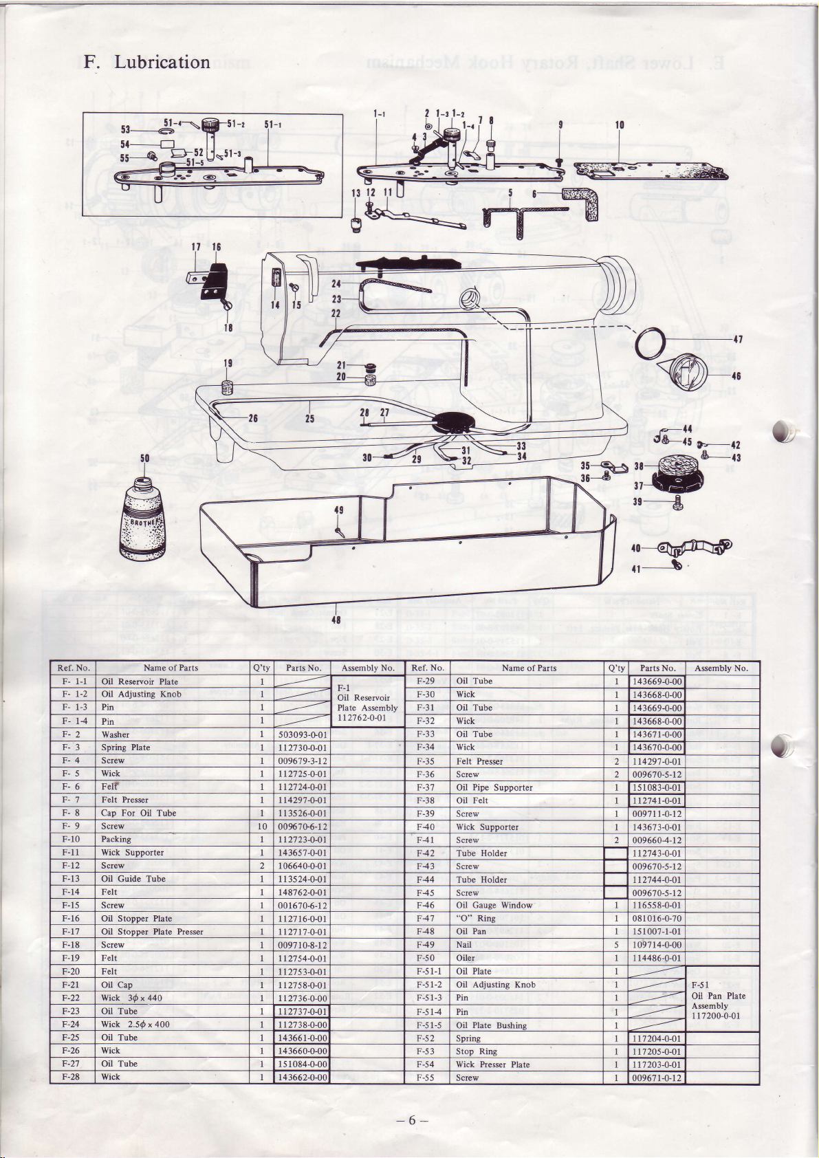
Lubrication
sl_--€-'\ffist-'
ii5"_=--,,[=u,-,,
r---@%
i
ryW
'%o.
KW-"
No. Name of
Ref.
F- l-l
Oil Rercryoir Plate
F- t-2 Oil Adjusting Knob
r- l-J
Pin
F- 14
Pin
r- 2
Washer
F-3 SDtins Plate
F-4
Screw
F-5 Wick
F-6 Felf
F-7
F-8 Cap For
F-9
F-10 Packing
F-11 Wick Supporter
F-t2 Screw
F-13 Oil Guide Tube
F-14 Fell
F-15
F-16 Oil StoDDer Plate
F-17 Oil Stopper Plate Prespr
F-18 Scrcw
F-19 Felt
F-20 Fell
F-21 Oil Cap
F-22 Wick 3@ x 440
F-23 Oil Tube
F-24 Wick 2.5@ x 400
F-25
F-26 Wick
F-27
F-28
Press!
Felt
Screw
Screw
Oil Tube
Oil Tube
Wick
Parts
Oil Tube
28
Parts No. Assembly No. Ref. No. Name
Q'ty
F-1
Oil Reseryoir
Plate Asrembly
t12762-0-01
503093-G0l
I I
2730-0-01
oo9679-3-12
272s-0-O
2724-0-0
429'14-0
3526-0-0
l0 0096'7U6-12
2'7234-0
365?-0-0
06640-0-0 F43 Screw
3524-0-0
8762-0-0
001670-6-r 2
I 12716-0-01
-0-01
tt27 1,7
0097 10-8-r
2
2754-0-0
2'ts3-o-0
27s8-0-0
2736-0-00
2737-O-O
2'138-O-O(
4366 1-0-0(
3660-0-0( F-53
1084-0-0( F-54 Wick
3662{-0(
F-29 Oil Tube
F-30
F-31 Oil Tube
F-32 Wick
F-33
r-J+ Wick
F-3s
F-36 Screw
-37
F
F-38 Oil Feh tt274t-o-o1
F-39 Screw
F40 Wick Supporter
F41 Screw
F42 Iube
F44 Iube
F45
F46
F47
F48 Oil
F49 NaiI 1 097 14-0-00
F-50 Oi.ler 1 14486-0-01
2
F-
F- 3 Pin
F Pin
-5
F
r-Jz
t-)) Screw
-ll
d&-o
i€&-{3
38
:ffih
3t
---€
39
--qd4\@
b
Puts
of
Wick
Oil Tube
Felt Presrer
Pipe
Oil
Supporter I 083-0-01
Holder
Holde!
Screw
Oil Gauge Window 1 16558-0-01
"O" Ring
Pan
Oil Plate
Adjusting
Oil
Plate
Oil
Spring 1l',l204-0-01
Stop Ring 1 1?205-0-01
Knob
Bushins
Presser Plate 1
Pilts No. Asembly No.
Q'tv
143669{-0C
143668-0-00
143669{-00
r43668-0-00
1436714-00
r43670-0-00
t1429'7-0-01
009670-s-12
0097 11-0-r2
143673-0-01
0096604-12
t12743-0-01
009670-5-12
112744-0-01
009670-5-1 2
081 016-0-?0
15 1 007-1-01
17203-0-01
00967 t-o-r2
F--{2
F-51
Pan
Oil
Plate
Assembly
I 1 7200-0-01
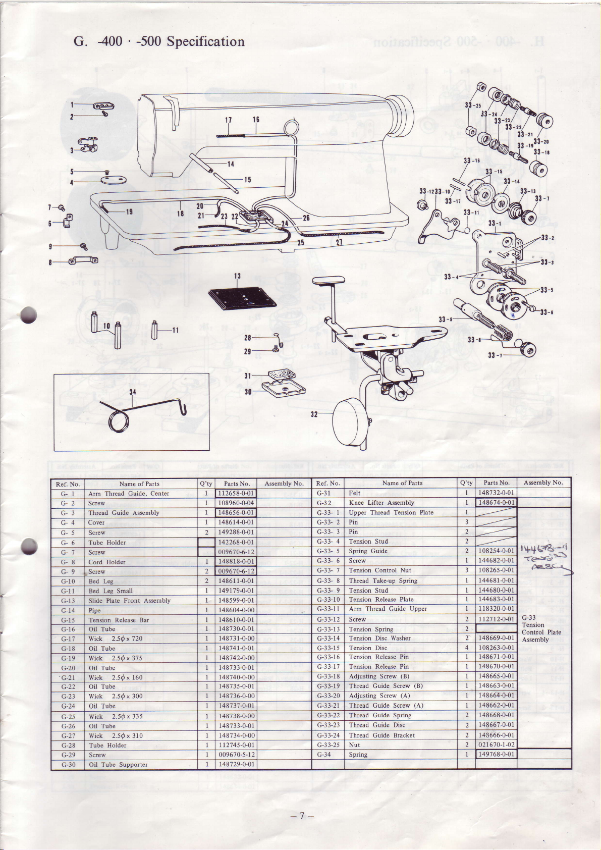
G.
r-----@
eJ
400
'-500
Specification
P
33
-z:
o
r-q
'-d
e-----Q
r---@
ffi
s-W
5-----------t
r-._G
Ir
H
[f-"
r,t
n
S
t3
I
2t-----€
29
le
go
bWP.P,
*qa'
\9
33-tl
33
|3-r:
-t
F
o
No.
Ref.
Arm
GI
Screw
G-3 Thread
G-4 Cover
G-5 Screw
G-6 Tube
G-7 Screw
Cord
G8
G9 Screw
Bed Les
c-10
Bed Is Small
G
G- 3 Slide
4 Pire
G-
J
G-
Tension
Oil Tube
G-16
c-l7 Wick 2.5Q x 720
Oil Tube
G-I8
G-I9 Wick
G-20 Oil Tube
'c-27
Wick
Oil Tube
G-22
G-23 Wick
Oil Tube
G-25 Wick
G-26 OiI Tube
Wick 2.54 x 3fi
G-2'l
Tube Holder
G-28
c-29 Screw
c-30 Oil
Nme of
Thread Guide, Center
Guide Assembly
Holder
Holder
Plate Front Assembly
Relsre Ba
2 .5Q x 37 5
2.5Q x 16O
2.5O x 300
2.5Q x 335
Tube Supporter
Puts
Parts No. Assembly
Q',ty
I 1 26s8-0-0t G-31
r08960-0-04 Knee
r486s6-0-0r
1486 l4-0-01
r49288-G0
t42268-0-01
0096704-12
1488r8-G01
009670-6-l
1486 1 1-0-01 c-33- 8 Thread Take-up Spring
1491794-01
148s99-0-01
148604-0-00
1486 10-0-01
148730-0-01
1487 3 1-0-00
14874 1-0-01 c-3 3-15
148',142-0-00
1487 33-0-01
148740-0-00
148735-0-01 G-33-19
148736-0-00 G-33-20
148737-0-0r
148738-G.00
1487 3 3-0-01
148734-0-00 Thread Guide Bracket
112'145-0-01 G-33-25
oo9670-5-12 G-34 Spring
t48'729-0-O1
No. Ref.
No
Felt
Lifter Asremblv
Upoer Thread Tension
2 Pin
G-33-
G-33G-33- 5
U.JJ- O Screw
c-33- 9 Tension Stud
G-33-10
G-33-1
G-33-13
G-33-14
G-3 3-16
G-33-t1
G-33-18
G-33-21
G-33-22 Thread Guide
c-3 3-23 Thread Guide
Pin
4 Tension Stud
Spring Guide
Tension Contol
Tension Release
1 Arm Thread Guide Upper
Screw
Tension Spring
Tension Disc
Tension Disc
Tension Release
Tension Release Pin
Adjusting Screw
Thread Guide
Adjusting Screw
Thread Guide
Nut 021670-1-02
Name
Parts
of
Plate
Nut 10826s{-01
Plate 144683{-0r
washer 148669{-0r
Pin 14867 1
(B)
(B)
Screw
(A)
(A)
Screw
Spring
Disc I
Puts No. Asembly
Q'tv
148?32{-0r
148674-G0t
r 082s4-0-01
144682441
144681{-0r
144680{-01
r r8320-0-0r
rl27t24-01
108.263-0-01
148670{-01
14866s{-01
148663-0-01
1 48664-0-01
148662-0-01
1 48668-0-01
48667-0-01
148666-0-01
149768{-01
-0-01
':s
Fe.a<-\
U-JJ
Tension
Contiol Plate
Asrembly
No.
-7 -
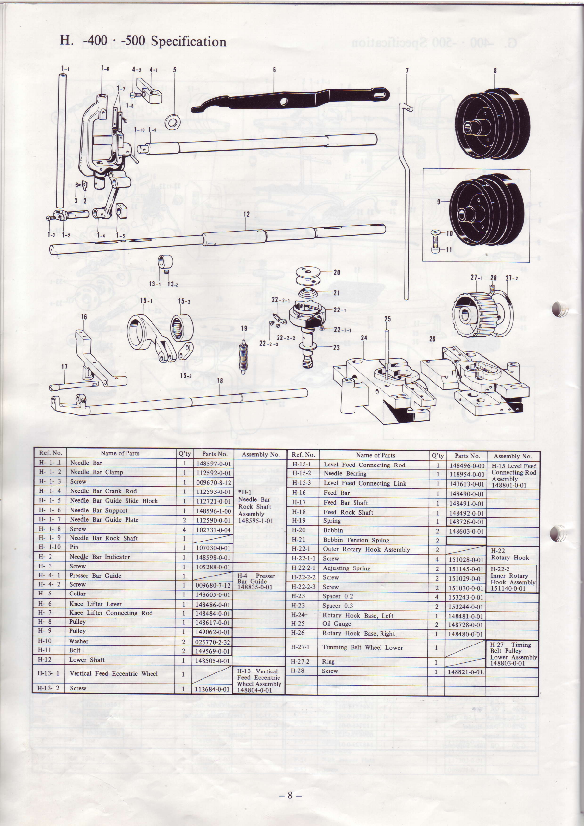
H.
-400
.-500
Specification
1-r
!+
1-z
{-r i 6
n l,-, INL
ll flffi.l
rw,
ll
llr$uH
ffidm
t-ri-zi-,i-rFffi
ts-i
i N@
p\
=,ut-f
I
,2
li--\
\9J
f5' Q-zo
il-,
j,,1Y,ffi';
222i.
g
\Y
,r-r-,.Q-"
R-;
il
\
ll
a
:
Ref. No.
H-
l-l Needle
H-t-2 Needle
H-l-3
H-1-4 Needle
H-1-5
H-1-6
H- t-'7 Needle
H-1-8
H-1-9
H-
1-10 Pin
H-2
H-3
H-4-I
H-4-2
H-5
H-6
H-'t Knw Lifter
H-8 Pulley
H-9
H-10
H-l1
H-12
H-13- I Vertical
2 Screw
H-t3-
Screw
Needle Bu
Needle
Screw
Needle Bil
Needle
Screw
Presrcr
Screw
Collu
Kn€
Lifter LeYer
Pulley
Washer
Boll
Lower
Shaft
Bu
Bil
Br Crmk Rod
Bar
Bd
Ba Indietor
Bu
Feed
Name
Pdts
of
ClamD
Guide Slide
Support
Guide
Rock Shaft
Guide H4 Ptesser
Connectins
Eccentric Wheel
Block
Plate
Rod
Parts
No.
Q'ty
14859?-0-01
112592-0-0r H 5-Z
009670-8-1
1 12593{-01
r12721-0-01
r48596-l-00
2 r I
2s90-0-01 H-l9
l
0273 1-0-04 H-20
I
07030-0-01
148598{-01
10s288-0{l
009680-7-12
148605-G.01
148486-0{l
4E484-0-01
148617{-01
149062{-01
2
025770-2-32
2 149s69-0-01
r48505-0-01
I
1 12684-0-0r
Assembly No.
2 H 5-3 Level
*H-1
Needle
Bar
Rock
Shaft
Assembly
148595-1-01
Bu Guide
148835+01
H-13
Vertical
Feed Eccentuic
Wheel Assmbly
1 4R804-OJr I
Ref.
No.
H
5-1
LeYel Feed
Needle
H
6
H.
H-
H-21
H-22-1
H-22-I-1
H-22-2-l
H-22-2-2
H-23
H-23
H-2+
H-25 Oil
H-26
H-27-1
H-2'.7-2 Ring
H-28
Feed Bar
7
Feed Btr
8 Feed
Spring
Bobbin
Bobbin
Outer Rotary
Screw
Adjusting
S crew
Screw
Spacer 0.2
Spacer
Rotary Hook
Rotuy
Timming
Screw
Feed
Rock
0.3
Gaug€
Nam€
Connectins
Bearing
Connectins
Shaft
Shaft
Tension
Hook
Spdng
Base, Lefl
Hook
Base,
Belt Wheel
of Parts
Spdng
Right
Rod
Link
Assembly
Lower
Pdts
Q'tv
2 148603{-01
2
2
2
2 l
2 ls
4
2 I 5 3244-0-0t
I r48481-0-01
2
No.
148496-0-00
I 18954-0-00
14361
3{-01
148490-0-01
t48491-0-01
r48492-0-01
r4u726-0-01
r
s r 028-0-01
151145{-01 H-22-2
5 1 029-0-0t
1 030-0-01
t53243-0-0t
148728-0-01
148480-0-01
148821-0-01
Assembly No.
H-15 Levet
Connecting
Assembly
148801-0-01
H-22
Rotary
Inner Rotary
Hook Assemblyl
H-27 Timing
Belt Pulley
148803-0{r
Hook
Feed
Rod
).
|
I
-8-
-
-400 ' -500
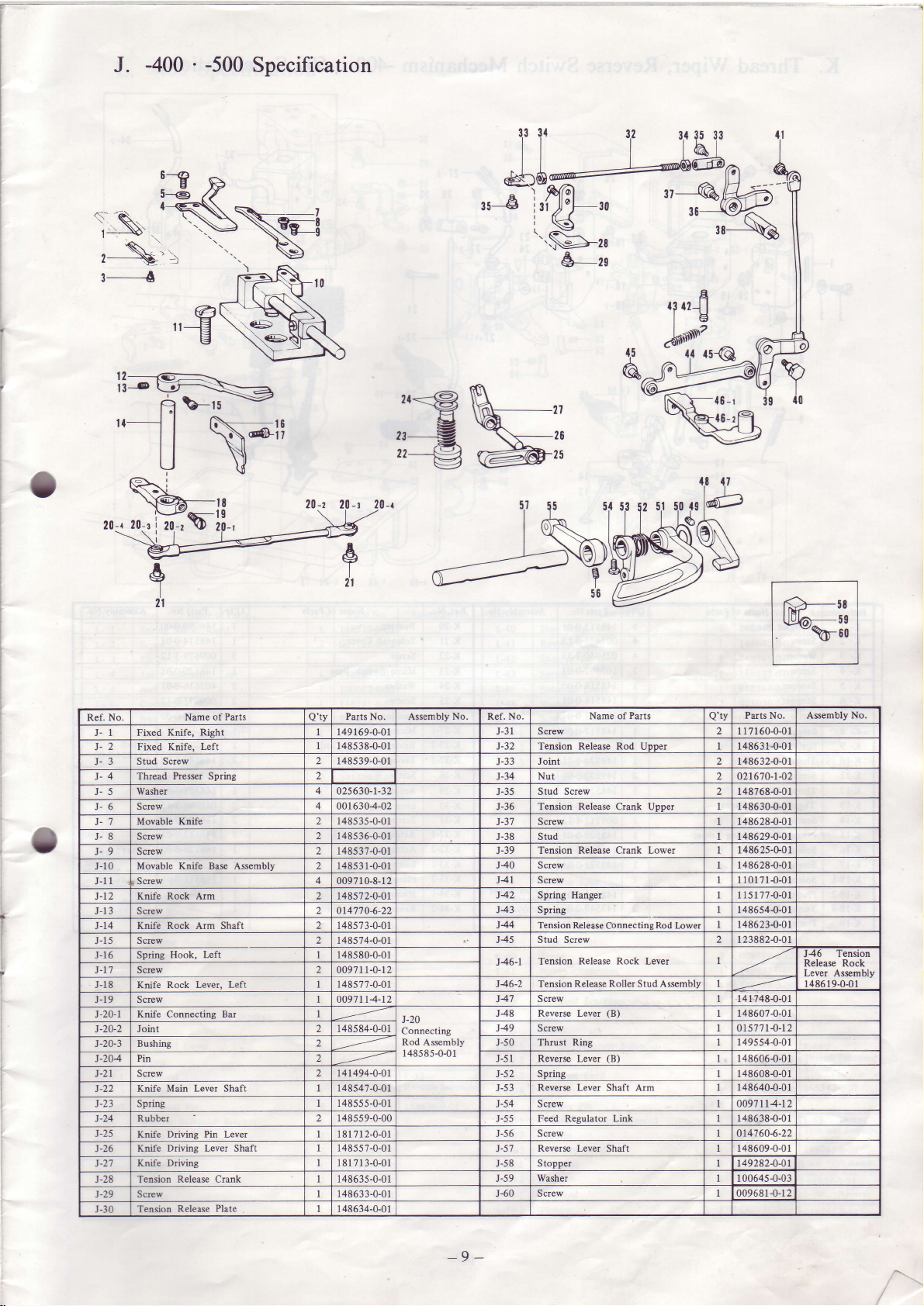
J.
Specification
rs-€
n
@1fu45-
:+\.
,
\lt
s___6
O
a
li___g+=''-Hu-F:
| \@le
UN
%-,,
2o-rro-,'ff1t-13
,t
,
zo-z
2o-,
\
t"'
zo'
zr@
,r-€r
,r--€
2t
26
25
gI
21
Puts
No.
Ref.
1 Fixed
2 Fixed
3 Stud Screw
Thread
Washer
5
Screw 0016304-02
6
Movable Knife
7
8 Screw
9 Screw
10 Movable Knife Bap Assembly 2 1485 3 1-0-01
11 Screw
l2 Knife Rock Arm
IJ
Screw
t4 Knife Rock Arm Shafl 14857 3-0-01
-15
Screw 1
16 Spring
t'l Screw 00971 1-0-1 2
-18
Knife Rock LeYer,
19 Screw 009'1114-12
20-l Knife Connecting Bar
Joinl 1485 84-0-01
20-2
20-3 Bushing
204 Pin 5l Rever$ Lever
21 Screw
22 Knife
z3
Sprine
24 Rubber
25
Knife Drivins
-26
Knife Drivins Lever Shaft
27 Knife Driving
-28
Tension Release Cruk
-29
Screw 1486 3 3-0-0 l
30 Tension
Name of
Knife, Right 149 169-0-01
Left
Knife,
Presrer
Spring
Hook, Left
Left 1 48577-0-01
Mair Lever Shaft 148547-0-01
Pin
Lever
Plate
Rele6e
Parts
Q'tv
148s
38-0-0 1 J-32 Tension Release Rod Uooer 14863 1-0-01
2 1485 39-0-01
2
4
02s630-1-32 J-J)
2 1485
35-0-0 i
2 148s
36-0-01
2
1485 37-0-01
0097 1
148s72-0-01
0147'104-22
48574-0-01
48580-0-01
1
14 1494-0-01
r48555-0-01
148ss9-0-00
181712-0-01
14855
181
7l 3-0-01 58
1486
35-0-0 I
I 48634-0-0
Assemblv No. Ref. No.
No.
J-31 Screw 1 I 7 160-0-01
J.JJ Joinl r486324-01
Nut
J-34
Stud Screw 148768-0-01
Tension Release
J-36
r-37 Screw 148628{-01
J-38 Stud 148629-0-01
J-39 Tension Release Crank
J40 Screw 148628{-01
2
0-8-1
J-20
Connecting
Rod Assembly
1 485 8s-0-0
7-0-01 5'.? Reverse Lever Shaft 148609-0-0 I
I
t41 Screw 1 101 7 1-0-01
J42 Spring Hanger ll5l7?-0-01
t43 Spring I
144 Tension
J45 Stud Screw l 23882-0-0 I
Tension
t46-l
Tension Release
41
Screw 141748-0-01
48 Reverse Lever
49 Screw 0t5't't l-o-12
1
50 Thrust Ring
52 Spring I
-)J
Reverse Lever Shaft Arm 148640-0-0r
54 Screw 009't lt4-12
55 Feed Reeulator Link 148638-0-01
56 Screw 014760-6-22
Stopper t492824-01
59 Washer
-60
Screw
Parts
Name of
Crank UDDer
Release Connectins
Release Rock Lever
Roller Stud Assmbly
(B)
(B)
Pilts No
Q'tv
021670-1-O2
148630{-01
Lower 14862s-G0l
486s4-0-01
Rod
l-wer
148623-0-01
I
148607-0-01
149554-0{l
148606-0-01
48608-0-0r
10064s{-03
009581{-12
Assembly No.
lgnslon
J+O
Releare Rock
Lever Assembly
i486 19-0-01
-9
-
 Loading...