

Page 1
HIGH
SPEED
BAR
TACKING
MACHINE
VERRIEGELUNGSSCHNELLNAHER
MACHINE A COUDRE A POINTS
LIBRE
MAOUINA
BARRA
~-
INSTRUCTION
BEDIENUNGSANLEITUNG
MANUEL
MANUAL
--
PRESILLADORA
DE
BRAZO
LIBRE
--
MANUAL
D'INSTRUCTIONS
DE
INSTRUCCIONES
D'ARRET A GRANDE
DE
DOBLE
PESPUNTE
--------
VITESSE
DE
ALTA
DU
TYPE
VELOCIDAD
BRAS
CON
LK3-B430
L--
1
-----J
Page 2
-
1
<
'·
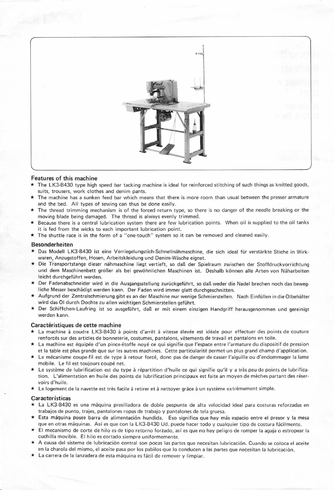
Features
*
The
suits, trousers,
*
The
and
*
The
moving
* Because
it
*
The
of
this machine
LK3-B430
machine has a
the
bed.
thread
is
fed
shuttle
trimming
blade
there
from the wicks
race
Besonderheiten
* Das Modell
waren,
LK3-B430
Anzugstoffen,
* Die Ti-ansports
und
dem
Maschinenbett
Ie
icht
durchgefi.ihrt
*
Der
Fad
enabschneider
1 iche Me sser
*
Aufgrund
wird
das
*
Der
Schiffchen
werden
Caracteristiques
* La
machin
forces
ren
* La mach ine
et
Ia
table
* Le
mecani
mobile.
* Le
systeme
tio n.
voirs
d'huil
* Le l
ogement
Caracteristicas
* La LK3-
trabajos
*
Esta maquina
que
en
*
El meca
cuch
illa movi
* A
causa
en
Ia
charola
* La
carrera
beschadigt werd
der
01
durch
kann.
e a coudre LK3-
sur des
est equipee
est plus
sme
Le fil
de lubri
L'alimentation
e.
de
B430
de
pun
otras maq
nismo
ble.
del si
del mi smo, el aceite
de
type
high
work clothes
sunken
All
types
of
mechanism
being
damaged. The
is a central
to
is in
the
ist
Hosen, Arbeitskleidung
tan
ge dieser
groBer als bei
werden.
wird
Zentralschm
Dochte
-Laufring ist
de
cette
articles
coupe
est
Ia
es una maquin
to,
posee
uin
de
ste
ma de
Ia lanzadera
de
d'un
grande
-til
est
toujours
fication
en
huile
navette
trajes,
barra
as.
Asi
corte
de
El
hilo es
lubricaci6n cen
que sur
pan
de
speed
bar tacking
and
denim
feed
bar
which
sewing can
is
of
thread
lubrication
each important
form
of a "one-
eine
Verriegelungstich-Schnel lna
nahmaschine
in die Ausgangsstellung zuri.ickgefi.ihrt,
en
kann. Der
ierung
gibt
zu
allen
wichtigen
so
ausgefi.ihrt, daB
machine
pant
s.
means
thus
be
done
the
forced return
is
alway
system there
lubrication
touch"
und
liegt
vertieft,
gewohnlichen
Faden
es
an
der
Masc
Schmierst
is ide
that
there
easily.
type,
s eve
nly
are
few lu
point
system
Denim-Wasc
wird
er
so
so
Maschinen ist.
immer glatt
hine
nur wenige
ellen gefi.ihrt.
mit
einem
al
hmaschine
daB
machine
B430 a point
bonnet
pince-etof
les
de
type a retour
coup
e net.
est
du
des
est
tres
facile a
a presilladora
talones
de
alime
es que
hilo es de
cortado
pasa
esta
maq u ina
s d'
arret
erie,
costumes,
fe
noye
autres
machines .
force,
type
a re
partition
poin
ts
de lubrification
retirer
de
ropas
de
traba
ntacion
con
tipo retorno
siempre uni
hundid
Ia LK3-B430 Ud.
tral son
por
los
pabilos
es
facil
a vitesse elevee
pantalon
ce
qui signifie
eta
doble
jo y p
forzado,
form
poc
as las
de
s,
Cette
done pas de
d'h
uile
principaux est
nettoyer
pespunte
antalones de
a.
Eso significa
puede
as i es
emente.
partes
que
lo
rem over y limpiar.
con
for
reinforced
is
more
so
there
trimmed.
brication
.
it can
be
he
eignet.
der
so
durchgeschn
einzigen
est ideale
vetements
que l'espace
par
tic
ular
danger
ce
qui signifie qu'il y a tres
grace a
de alta
hacer
que
que
duc
en a las p
stitching
room
than
is
no
danger
points. When
removed
, die sich ideal fur
Spielr
aum
Deshalb
daB
weder
itte
Schmierstellen.
Han
dgriff
pour
de
tra
vail
entre !'ar
ite
permet
de
casser
faite an
un
syste
me
velocidad ideal p
tela
gruesa.
que
hay
mas
todo y cualquier tipo
no hay
necesitan lubricacion.
pel i
artes que
of
such
things
usual
between
of
oil
and cleaned
zwischen der
konnen aile
di e Nadel brec
n.
Nach Einfi.illen in
herausgenommen
effectuer
et
pantalons
mature
un
plus
l'aiguille
moy
en de
extremement simple.
espacio
gro
de
romper
necesitan
the
the
needle
is supplied
easily.
verstarkte
Stoffdruckvorrichtung
Arten
hen
des
en
toile.
du
di sp
grand
champ
ou
d'endommager
peu
de
point
mech
es pa
ara
costuras
entre
el
de
costura
Ia
aguja o es
Cuando
Ia lubricacion.
as
knitted
presser
breaking
to
the
Stiche
von
Naharbeiten
noch das
die
und
points
osit
if
de
d'a
s de lubrifica-
rta
nt
reforzadas
pre
sor y Ia
facilm
se col
oca
goods,
armature
or
the
oil
tanks
in Wirk-
beweg
Olb
ehalter
gereinigt
de couture
pression
ppl
ication
Ia
lame
des
n!ser-
en
mesa
ente.
tropear
el
aceite
-
.
Ia
Page 3
Contents
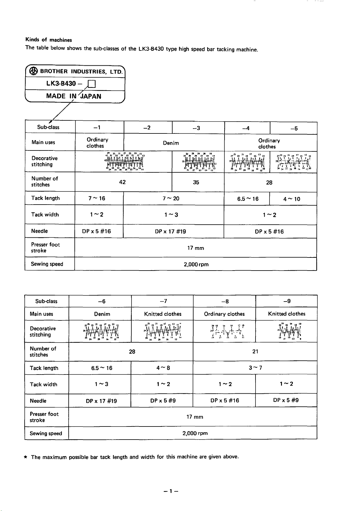
Kinds
of
machines
table . . . . . . . . . . . . . . . . . . . . . . . . . . . 5
Power
Installing
Installing the machine
Installing
Motor
Installing
Installing the bobbin winding thread
Installing
Installing
Lubrication . . . . . . . . . . . . . . . . . . . . . . . . . . . 12
Trial operation . . . . . . . . . • . . . . . . . . . . . . . . . 13
Checking
Basic operation
Basic operation
Basic operation
Basic operation
Installing
Upper threading . . . . . . . . . . . . . . . . . . . . . . . .
Selecting a needle and thread. . . . . . . . . . . . . . . .
Bobbin winding
Inserting
Lower thread tension . . . . . . . . . . . . . . . . . . . . .
Upper thread tension . . . . . . . . . . . . . . . . . . . . . 22
Thread take-up spring. . . . . . . . . . . . . . . . . . . . . 22
Using
Cleaning
Replacing
Needle bar height adjustment. . . . . . . . . . . . . . . .
Needle bar stroke adjustment. . . . . . . . . . . . . . . .
Needle and shuttle
Shuttle driver and needle
Shuttle race thread guide adjustment. . . . . . . . . . . 27
Brake spring tension adjustment. . . . . . . . . . . . . . 27
Needle and feed timing
Thread take-up lever adjustment. . . . . . . . . . . . . . 29
Tack
Tack width adjustment. . . . . . . . . . . . . . . . . . . .
Work clamp stroke adjustment
Moving
Thread wiper adjustment . . . . . . . . . . . . . . . . . .
Drive lever plate stopper A position adjustment
Drive lever plate stopper B position adjustment
Trouble shooting. . . . . . . . . . . . . . . . . . . . . . . .
the
the
pulley and belts . . . . . . . . . . . . . . . . . . . . 9
the
the
the
the
the
and removing
lower threading. . . . . . . . . . . . . . . . . . . .
and
the
stop
the
the
length adjustment . . . . . . . . . . . . . . . . . . .
blade position adjustment. . . . . . . . . . . . .
(Mechanical two-pedal systems) . . . . . . . . . . . .
(Mechanical two-pedal systems)
......................
motor.
motor
spool holder base . . . . . . . . . . . . . . 9
pedal . . . . . . . . . . . . . . . . . . . . . . 10
belt cover . . . . . . . . . . . . . . . . . . . 12
basic operation
needle. . . . . . . . . . . . . . . . . . . . . .
shuttle race. . . . . . . . . . . . . . . . . . . 23
. . . . . . . . . . . . . . . . . . . . . 6
head.
. . . . . . . . . . . . . . . . 7
pulley and
of
the
power presser lifter . . . . . . .
of
the
upper tension discs . . . . . . .
of
the
clutch.
of
the moving blade . . . . . . . . . . .
.........................
the
lever. . . . . . . . . . . . . . . . . . . . . . 23
fixed and moving blades . . . . . . . . .
hook
adjustment.
belts.
. . . . . . . . . . 8
guide.
of
the
machine . . . . .
. . . . . . . . . . . . . . . 17
bobbin case
clearance adjustment . . . . 26
contact
adjustment . . . . . 26
. . . . . . . . . . .
...............
............
.
. . . . . . 10
14
15
16
18
18
19
19
20
21
21
24
25
25
28
30
30
31
32
33
34
35
36
I nhaltsverzeichnis
Einteilung
Motorgestell. . . . . . . . . . . . . . . . . . . . . . . . . . . 5
Aufstellung
Aufstellung des Maschinenoberteils. . . . . . . . . . . . 7
Montage der Riemenscheibe und der Gurte. . . . . . . 8
Motorriemenscheibe und Gurte . . . . . . . . . . . . . . 9
Der
Anbringungsanleitung des
Montage des pedals . . . . . . . . . . . . . . . . . . . . . .
Montage des Riemenschutzes. . . . . . . . . . . . . . . . 12
Schmierung . . . . . . . . . . . . . . . . . . . . . . . . . . . 12
Probebetrieb. . . . . . . . . . . . . . . . . . . . . . . . . . . 13
Oberprufung des Nahmaschinenbetriebs. . . . . . . . .
Arbeitsweise des StoffdriickeriUfters . . . . . . . . . . .
Arbeitsweise der oberen Spannscheiben. . . . . . . . . 16
Arbeitsweise der
Arbeitsweise des
Nadelbefestigung. . . . . . . . . . . . . . . . . . . . . . . .
Einfadeln des Oberfadens . . . . . . . . . . . . . . . . . . 19
Nadel und Nahfaden . . . . . . . . . . . . . . . . . . . . . 19
Der
Einlegen
und Einfadeln des Unterfadens. . . . . . . . . . . . .
Unterfadenspannung . . . . . . . . . . . . . . . . . . . . .
Oberfadenspannung. . . . . . . . . . . . . . . . . . . . . . 22
Fadenabnahmefeder. . . . . . . . . . . . . . . . . . . . . . 22
Der
Reinigung des Schiffchen-Laufrings
Auswechsel n der bewegl ichen
und festen Messer . . . . . . . . . . . . . . . . . . . . .
Einstellung
Einstellung des Nadelstangenhubs. . . . . . . . . . . . .
Einstellung des Abstands zwischen Nadel
und Schiffchennase . . . . . . . . . . . . . . . . . . . . 26
Einstellung
Schiffchen-Mitnehmer und
Einstellung des Fadenfuhrers
Schiffchen-Laufring. . . . . . . . . . . . . . . . . . . . 27
Einstellung der Bremsenfederspannung . . . . . . . . . 27
Einstellung des Nadel und
Transporteurgleichlaufs . . . . . . . . . . . . . . . . .
Einstellung des Fadenabnahmehebels . . . . . . . . . . 29
Einstellung
Einstellung der Verriegelungsweite . . . . . . . . . . . .
Hubverstellung des StoffdruckerfuBes . . . . . . . . . . 31
Positionierung des
Einstellung des Fadenwischers . . . . . . . . . . . . . . . 33·
Positionierung des Plattenanschlags A
(Die mit zwei mechanisch betatigten
ausgerustet sind) . . . . . . . . . . . ... . . . . . . . . .
Positionierung des Plattenanschlags B
(Die
ausger
Fehlersuche . . . . . . . . . . . . . . . . . . . . . . . . . . .
der
Nahmaschinen. . . . . . . . . . . . . . . . 2
der
Maschine . . . . . . . . . . . . . . . . . . 6
Spulentrager. . . . . . . . . . . . . . . . . . . . . . . . 9
Spuler-Fadenfuhrers . . . . 10
10
14
15
Kupplung . . . . . . . . . . . . . . . . . 17
beweglichen Messers . . . . . . . . . .
Spulvorgang . . . . . . . . . . . . . . . . . . . . . . . . 20
und Entnehmen der Spulenkapsel
Stopphebel . . . . . . . . . . . . . . . . . . . . . . . . . 23
...
-.
. . . . . . . . 23
der
Nadelstangenhohe. . . . . . . . . . . . . 25
der
Beruhrungsflache zwischen
Nadel.
im
der
VerriegelungsUinge . . . . . . . . . . . .
beweglichen Messers. . . . . . . . .
mit
zwei mechanisch betatigten pedal en
ustet sind). . . . . . . . . . . . . . . . . . . . . .
. . . . . . . . . . 26
pedalen
18
18
21
21
24
25
28
30
30
32
34
35
38
Page 4
Table des math\res
Differentes machines a coudre . . . . . . . . . . . . . . . 3
Ia
Plateau de
Installation
Installation
Installation
et
des courroies. . . . . . . . . . . . . . . . . . . . . . . 8
Poulie
Socle
Montage
Installation
Installation
Huilage . . . . . • . . . . . . . . . . . . . . . . . . . . . . . . 12
Essai
de
Verification des fonctions
Fonction
Fonction de base des tendeurs
Fonction de base
Fonction de base
Mise
en place
Enfilage superieur . . . . . . . . . . . . . . . . . . . . . . . 19
Aiguille
Bobinage
Mise
en place
canette
Tension
Tension
Ressort
Utilisation du levier
Nettoyage
Changer
Reglage
Reglage de
Reglage
du
Reglage
navette
Reglage
Reglage
Reglage
aiguille-alimentation. . . . . . . . . . . . . . . . . . . .
Reglage
Reglage
Reglage
Reglage
Positionnement
Reglage
Reglage
levier
mecaniques) . . . . . . . . . . . . . . . . . . . . . . . . .
Reglage
levier
mecaniques) . . . . . . . . . . . . . . . . . . . . . . . . .
Guide
machine. . . . . . . . . . . . . . . . . . . . . 5
du
moteur
de
Ia
de
Ia
du
moteur
du
porte-bobine . . . . . . . . . . . . . . . . . . . . 9
du
guide-fil . . . . . . . . . . . . . . . . . . . . . 10
de
Ia
du
couvercle des courroies. . . . . . . . . . 12
Ia
machine . . . . . . . . . . . . . . . . . . . . . .
de
base
de
et
fil
. . . . . . . . . . . . . . . . . . . . . . . . . . 19
de
Ia
canette . . . . . . . . . . . . . . . . . . . .
et
et
enfilage interieur. . . . . . . . . . . . . . . 21
du
fil
de
de
fil
de
du
tendeur . . . . . . . . . . . . . . . . . . . . . .
du
logement
Jes
lames fixe
de
Ia
hauteur
Ia
course
de
Ia
distance aiguille-pointe
crochet
de
du
contact
et
de l'aiguille. . . . . . . . . . . . . . . . . . .
du
guide-fil
de
Ia
tension
de
Ia
synchronisation
du
guide-fil . . . . . . . . . . . . . . . . . . . . . .
de
Ia
longueur
de
Ia
largeur
de
Ia
course
de
l'ote-fil. . . . . . . . . . . . . . . . . . . . . . .
de
Ia
position de
d'entrainement
de
Ia
position de
d'entrainement
de
depannage. . . . . . . . . . . . . . . . . . . . . .
. . . . . . . . . . . . . . . . . . . . 6
tete
de
Ia
machine . . . . . . . . . . . 7
poulie
du
moteur
et
courroies . . . . . . . . . . . . . . . 9
pedale . . . . . . . . . . . . . . . . . . . 10
de
base. . . . . . . . . . . . .
du
releveur
de
l'embrayage . . . . . . . . . . . . . 17
de
Ia
l'aiguille . . . . . . . . . . . . . . . . . . 18
depose
dessous . . . . . . . . . . . . . . . . . . 21
dessus . . . . . . . . . . . . . . . . . . .
d'arret
de
Ia
canette . . . . . . . . . . . . . . . . .
de
du
du
du
du
de
Ia
du
presseur. . . . . . . .
de
fil . . . . . . . . . . .
lame mobile. . . . . . . . . . . .
du
boitier
de
Ia
. . . . . . . . . . . . . . . . .
de
Ia
navette. . . . . . . . . . .
et
mobile. . . . . . . . . . . . . .
de
Ia
barre a aiguille . . . . . . .
Ia
barre a aiguille . . . . . . . .
l'entrainement
logement
ressort
du
point
point
pied-de-biche . . . . . . . . . . 31
lame mobile
Ia
butee A de
(Systeme a deux pedales
Ia
butee B
(Systeme a
de
Ia
de
Ia
navette
de
frein. . . . . . . . .
. . . . . . . . . . . . . .
. . . . . . . . . . . . . . .
.............
Ia
de
Ia
deux
....
plaque
plaque
pedales
13
14
15
16
18
20
22
22
23
23
24
25
25
26
26
27
27
28
29
30
30
32
33
du
34
du
35
40
I ndice
de
contenido
Diferentes tipos
de
Mesa
Montaje del
Montaje
Montaje
La
Base
lnstalacion
Montaje del pedal . . . . . . . . . . . . . . . . . . . . . . .
Montaje
Lubricacion . . . . . . . . . . . . . . . . . . . . . . . . . . . 12
Prueba
Comprobacion
Operacion basica del levantador del
Qperacion basica
Operacion fundamental del embrague . . . . . . . . . . 17
Qperacion fundamental
Montaje
H ilo superior . . . . . . . . . . . . . . . . . . . . . . . . . . 19
La
Como llenar
Para insertar y sacar
Tension del hilo inferior
Tension del hilo superior. . . . . . . . . . . . . . . . . . .
Muelle del tira hilo
Como usar
Como limpiar
Reemplazar las cuchillas movibles y fijadas. . . . . . .
Ajuste
Ajuste del curso
Ajuste del espacio
Ajuste
Ajuste
Ajuste
Ajuste
Ajuste
Ajuste
Ajuste
Ajuste del curso del pie prensor . . . . . . . . . . . . . .
Ajuste
Ajuste del libra-hilo . . . . . . . . . . . . . . . . . . . . . .
Ajuste
Ajuste
Localizacion
Ia
de
de
polea del
de
porta-conos . . . . . . . . . . . . . . . . . . . . . . 9
canilla. . . . . . . . . . . . . . . . . . . . . . . . . . . . .
de
de
de
Ia
maquina. . . . . . . . . . . . . . . . . . . . . . . .
prensor
de
tension superior . . . . . . . . . . . . . . . . . . . .
de
aguja y
can ilia e h ilo inferior . . . . . . . . . . . . . . . . . . . 21
de
de
Ia
lanzadera . . . . . . . . . . . . . . . . . . . . . . .
de
y del contacto
de
de
Ia
lanzadera . . . . . . . . . . . . . . . . . . . . . . . 27
de
de
y
de
Ia
de
de
de
de
de
palanca de mando (Sistemas mecanicos
pedales) . . . . . . . . . . . . . . . . . . . . . . . . . . . .
de
palanca de mando (Sistemas mecanicos
pedales) . . . . . . . . . . . . . . . . . . . . . . . . . . . .
de
Maquinas. . . . . . . . . . . . . . . . 4
maquina . . . . . . . . . . . . . . . . . . . . . . 5
motor.
Ia
Ia
de
Ia
operacion. . . . . . . . . . . . . . . . . . . . . .
de
Ia
el
Ia
Ia
altura
Ia
polea impulsora
Ia
guia del hilo
Ia
tension del freno
Ia
sincronizacion
aguja . . . . . . . . . . . . . . . . . . . . . . . . .
Ia
palanca del tira hilo. . . . . . . . . . . . . .
Ia
largura de puntada . . . . . . . . . . . . . .
anchura
posicion
Ia
posicion del tope A
Ia
posicion del tope B
. . . . . . . . . . . . . . . . . . . . . . 6
cabeza
de
Ia
maquina. . . . . . . . . . . . 7
polea del
motor
Ia
·cubierta
de
energia.
aguja . . . . . . . . . . . . . . . . . . . . . . 18
hilo. . . . . . . . . . . . . . . . . . . . . . . . 19
Ia
can ilia. . . . . . . . . . . . . . . . . . . . .
palanca
Ia
de
motor y de
y las correas . . . . . . . . . . . . . . 9
guia del hilo del devanador
de
correas . . . . . . . . . . . . . 12
Ia
operacion basica
. . . . . . . . . . . . . . . . . . . .
de
los discos
de
Ia
Ia
caja
de
...................
.......................
de
parada . . . . . . . . . . . . . .
carrera
de
Ia
de
Ia
barra
de
Ia
barra
de
de
Ia
aguja y del gancho
de
Ia
aguja . . . . . . . . . . . . . . . .
de
de
de
puntada . . . . . . . . . . . . . . .
de
Ia
cuchilla movible. . . . . . . . 32
fallas
.....................
las correas. . . . . 8
de
Ia
cuchilla movible. . . . .
Ia
lanzadera . . . . . . . . .
de
Ia
aguja . . . . . . . .
Ia
aguja. . . . . . . . . .
de
Ia
lanzadera
Ia
carrera
de
muelle. . . . . . . . .
alimentacion
de
Ia
placa
de
Ia
de
dos
de
Ia
placa
de
Ia
de
dos
10
10
13
14
15
16
18
20
21
22
22
23
23
24
25
25
26
26
27
28
29
30
30
31
33
34
35
42
Page 5
Kinds
of
machines
The table below shows the sub-classes of the
r
~
BROTHER INDUSTRIES,
LTD~
LK3-8430 type high speed bar tacking machine.
'
Sub-class
Main
Decorative
stitching
Number
stitches
Tack length
Tack width
Needle
Presser
stroke
LK3-B430MADE IN
/
,
uses
of
foot
/
~
1APAN
-1
Ordinary
clothes
DP
x 5
#16
42
-2
DP
Denim
7-20
x 17
-3
n n
21 ~ 16
l~~l026221111
J
3
I
27
35
#19
17
mm
u
n
21
11
u
2J
19
IS
-4
Ordinary
clothes
:~
26
22 ~ 18
16
II 1210
DP
21
6.5-16
28
x 5
#16
4
-5
.......
10
Sewing speed
Sub-class
Main
uses
Decorative
stitching
Number
of
stitches
Tack length
Tack width
Needle
foot
Presser
stroke
Sewing speed
-6
Denim
27~t~
n
tt
II
2J ~ II
t :
I•
U U
10
26
28
6.5-.. 16
1-3
DP
x 17
#19
2,000rpm
-7
Knitted clothes
2:iM~~
t6
22
I.
14
21
~
••
16
12
Ordinary clothes
4-8
1-2
DP
DP X 5#9
17
mm
X 5
2,000 rpm
-8
#16
Knitted clothes
21
-9
2r~~
19
17
1$
IJ
u,
DP
x 5
#9
* The maximum possible bar tack length and width for this machine are given above.
-1-
Page 6
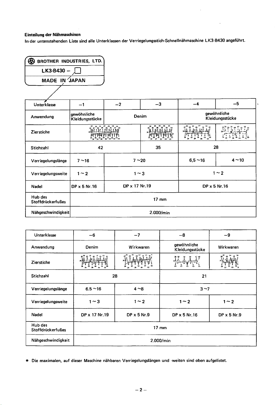
Einteilung der Nahmaschinen
In der untenstehenden Liste sind aile Unterklassen der Verriegelungsstich-Schnellnahmaschine LK3-B430 angefuhrt.
LTD.
'@
BROTHER
INDUSTRIES,
"""
L K3-B430 -
MADE
'
/
I!
Unterklasse
Anwendung
Zierstiche
Stichzahl
VerriegelungsUinge
Verriegelungsweite
Nadel
Hub
des
StoffdruckerfuBes
)J
IN
-'JAPAN
/
gewohnliche
Kleidungsstilcke
DP
-1
JO
·~J
a
eo11l6l41n30:t~o26zt22:.;.
7--16
1-2
x 5 Nr.16
~
-2
-3
Denim
za
24
~
JS
ll
21
23
19
..
1
15
~
•'u
32
)(
JO
JS~~
9 0 f ' .
3J
:<>
ll
42
26
27
35
II
u u
21
ll
"
16
12'
17
ll
15
7--20
1-3
DP
X 17 Nr.19
17
mm
-4
gewohnliche
Kleidungsstucke
17
25
21
27
2~~1
7 '
26
2
151J
23
19
~
~
22
••
,
u u
20
16
6,5--16
DP
II
~
10
28
1-2
x 5 Nr.16
-5
l7
~S
23
~I
10 17
!J~!J
..
';T-
!b
:•
IS
'~
~·~-~~,.~
';-{-tif-
·;~'
::
!0
II
lb
14
4--10
ll
II
I!IO
N ahgeschwind igkeit
Unterklasse
Anwendung
Zierstiche
Stichzahl
VerriegelungsUinge
Verr iegelungsweite
Nadel
des
Hub
StoffdruckerfuBes
Nahgeschwind igkeit
-6
Denim
6.5--16
DP
x 17 Nr.19
28
-7
Wirkwaren
DP
x 5 Nr.9
2.000/min
17 mm
2.000/min
-8
gewohnliche
Kleidungsstucke
DP
x 5 Nr.16
21
-9
Wirkwaren
1i,.W.i
7l,w-v·~
19 17
15
u
u,
DP
x 5 Nr.9
* Die maximalen, auf dieser Maschine nahbaren Verriegelungslangen und -weiten sind oben aufgelistet.
-2-
Page 7
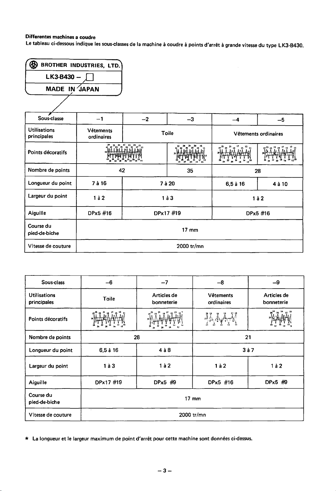
Differentes machines a coudre
Le
tableau ci·dessous indique
I'@
BROTHER INDUSTRIES,
LK3-B430 - .£)
les
sous-classes
LTD:
de
Ia
machine a coudre a points
d'arret
a grande vitesse
du
type LK3-B430.
MADE
"'
/
,
Sous·classe
Uti I isations
principales
Points decoratifs
Nombre de points
Longueur du point
Largeur
Aiguille
Course
pied-de-biche
Vitesse de couture
du
du
point
IN
<JAPAN
/
-1
Vetements
ordinaires
30
'2
·~~#tf
•Olll6JaUlOZ8262•n211"
1 a 16
a 2
1
#16
DPx5
l~
~
-2
Toile
ll
27
23
19
·~
a
"••
42
1 a
20
1 a 3
DPx17
-3
u
21
2•
:111
H
22
18
0 • r
21
19
••
u
12
17
IJ
~~
1•
33
JS~~~
33
11 n 21
35
#19
-4
Vetements ordinaires
23
21
~
2• n :Ill "
6,5
17
19
~
a 16
16
~~
u 1210
13
2725
~~
26
DPx5
-5
II
2~~A
Z6
z•
:z
:Ill
II
I•
1• U
28
4
a 10
1a2
#16
10
17 mm
2000
tr/mn
Sous~lass
Utilisations
principales
Points decoratifs
de
Nombre
points
Longueur du point
Largeur du point
Aiguille
Course
du
pied-de-biche
Vitesse de couture
*
La
longueur
et
le
largeur maximum
-6
Toile
21~~
26 n
••
Z0
a 16
1 a 3
u 10
lit
#19
de
t2
point
28
d'arret
Zt
6,5
DPx17
-7
Articles
bonneterie
2~72~$2l21191721SU~n•
2'1'1
..,
2'6
z•
DPx5
- '
ll
1a2
.1
20
... u
•'
#9
de
~
- "
•z
11.1
-8
Vetements
ordinaires
1
a 2
0Px5
17 mm
2000
tr/mn
pour
cette
machine sont donnees ci-dessus.
#16
21
-9
Articles de
bonneterie
2~
19
1~
17
13
DPx5
#9
n
9
-3-
Page 8
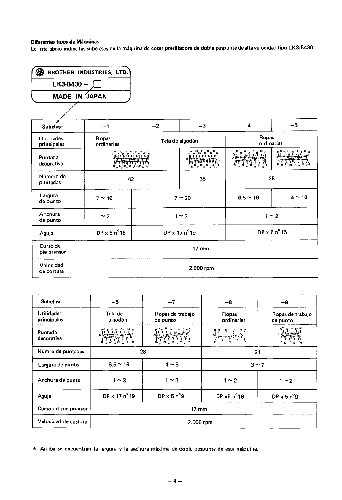
Diferentes tipos
La
lista abajo indica las subclases
de
Maquinas
de
Ia
maquina de coser presilladora
de
doble pespunte de alta velocidad
tipo
LK3-B430.
'(f)
BROTHER INDUSTRIES,
LK3-B430-
MADE IN
/
'
/
,
Subclase
Utilidades
principales
Puntada
decorativa
Numero
puntadas
Largura
de
Anchura
de
Aguja
de
punto
punto
;J
--JAPAN
-1
Ropas
ordinarias
LTD:
.)
42
-2
Tela
de
algod6n
u n
1:~
Jl
-3
-4
-5
Ropas
ordinarias
z•
20
16
0 I
29
2S
Jl
27
35
12
21
17
ll
21
19
IS
28
6.5,.., 16
Curso
del
pie prensor
Velocidad
de
costura
Subclase
Utilidades
principales
Puntada
decorativa
Numro de puntadas
Largura de
Anchura
de
punto
punto
Aguja
del pie prensor
Curso
-6
Tela de
algod6n
~~
26
:0
II
Ill
14 1210
22
24
6.5,..,
16
1-3
DP
X 17 n°19
28
Ropas
punto
de
-7
de
2.000 rpm
trabajo
17 mm
17mm
-8
Ropas
ordinarias
21
-9
Ropas
de
punto
de
trabajo
Velocidad
* Arriba
de
costura
se
encuentran
Ia
largura y
Ia
aAchura maxima
2.000
de
doble pespunte
rpm
-4-
de
esta maquina.
Page 9
Power table
Use
one
of
the following special
8430
type power tables.
Model
code
Motorgestell
Verwenden Sie eins der unten aufgelisteten 8430-Motorgestelle.
Modeii-Code
Table with
Motor and switch
assembly
*
If
purchasing a motor separately, select either of
following types.
Single phase 1
Three phase
Plateau de
Utiliser une des tables
Ensemble table
Element
commutateur
leg
Ia
machine
moteur
assembly
OOV
200V
de
avec pieds
Monophase
et
Triphase
128-201-430-49
Single
phase
Three
phase
type
184-256-001
184-281-001
4 pole 250W motor
4 pole
250W
8430
speciales suivantes.
Code de
128-201-430-49
184-256-001
184-281-001
motor
modele
the
Nahtisch
100V
maqu
einphasig
dreiphasig
ina
las
siguientes mesas especiales
Fase (mica
1-----+---------t
Fase
triple
Motor- und
Schaltgestell
*
Wenn
Sie einen Motor separat kaufen, wahlen Sie eine
der untenstehenden Motortypen:
Einphasig,
Dreiphasig, 200V
Mesa
de
Ia
Utilizar una de
8430.
Mesa
de
conjunto con pie
Cunjunto de motor
e interrupter
128-201-430-49
184-256-001
184-281-001
4 poliger 250W-Motor
4 poliger 250W-Motor
de
Codigo del modelo
128-201-430-49
184-256-001
184-281-001
tipo
*
Si
le
moteur est achete separement, choisir l'un des
types suivants.
Monophase 1
Triphase
OOV
200V
Ouadripole 250W
Ouadripole 250W
*
Si
se
compra
escoger uno de
F
ase
(mica 1
Fase triple 200V
*
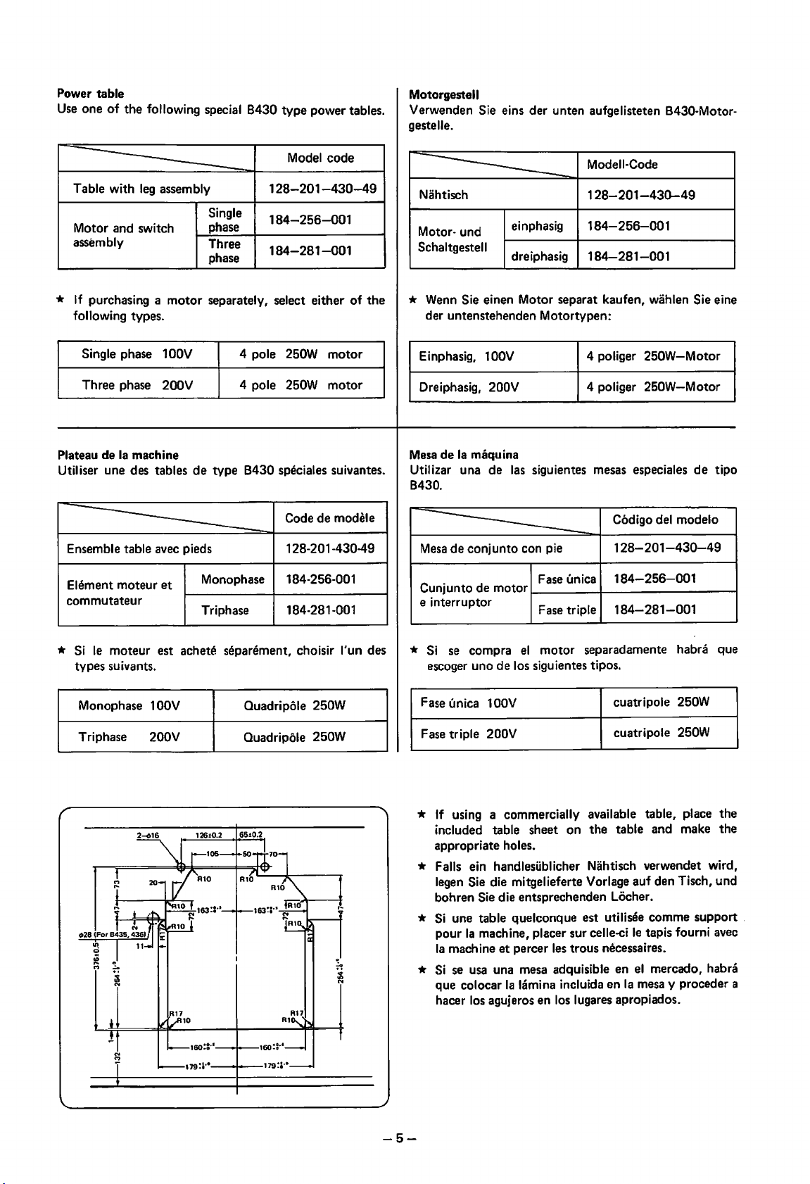
If
using a commercially available table, place the
included table sheet on the table and make the
appropriate
el
motor separadamente habra que
los siguientes tipos.
OOV
holes.
cuatripole 250W
cuatripole 250W
* Falls ein handlesilblicher Nahtisch verwendet wird,
legen
Sie die mitgelieferte Vorlage auf den Tisch, und
bohren
*
Si
pour
Ia
*
Si
que colocar
hacer
Sie die entsprechenden Locher.
une table quelconque est utilisee comme support
Ia
machine, placer sur celle-ci
machine et percer
se
usa
una mesa adquisible en
Ia
los agujeros en los lugares apropiados.
les
trous necessaires.
lamina incluida en
le
tapis fourni
el
mercado, habra
Ia
mesa y proceder a
avec
-5-
Page 10
Center
Motormittellinie
Centre
de
moteur
Centro del
motor
___
A_
: i
I :
II'
iT
M
m
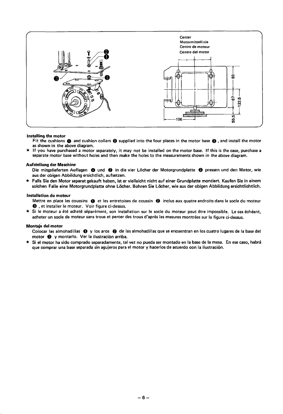
Installing the
Fit
as shown
* If you have purchased a motor separately, it may
separate
Aufstellung
Die mitgelieferten Auflagen
aus der obigen Abbildung ersichtlich, aufsetzen.
motor
the
cushions 0 and cushion collars
in
the
above diagram.
motor
base without holes and then make
der
Maschine
0 und
f)
supplied into
the
f)
in
die vier Locher der Motorgrundplatte 0 pressen und den Motor, wie
the
four
not
be installed on the
holes
to
the
places
in
the
motor
motor
measurements shown
base.
base 0 , and install
If
this
is
in
the case, purchase a
the
above diagram.
* Falls Sie den Motor separat gekauft haben, ist er vielleicht nicht auf einer Grundplatte montiert. Kaufen Sie
solchen
Installation
Mettre en place les coussins 0
0 ,
* Si
acheter un socle
Montaje
Colocar las almohadillas 0 y los aros
motor
* Si
que
Faile eine Motorgrundplatte ohne Locher. Bohren Sie Lecher, wie aus
du
moteur
et
les entretoises
et
installer
le
moteur a ete achete separement, son installation sur
del
0 y montarlo. Ver
el
motor
comprar una base separada
le
moteur. Voir figure ci-dessus.
de
moteur sans trous
motor
Ia
ha sido comprado separadamente, tal vez no pueda ser montado en
et
percer des trous d'apres les mesures montrees sur
f)
ilustraci6n arriba.
sin
agujeros para
de
coussin
de
las almohadillas
el
motor
f)
le
socle du moteur peut etre impossible.
que
y hacerlos
der
obigen Abbildung ersichtlichtlich.
inclus aux
se encuentran en los
de
quatre
acuerdo
Ia
base de
con
endroits dans
Ia
cuatro
Ia
Ia
ilustraci6n.
le
socle
figure ci-dessus.
lugares
mesa. En ese caso, habra
Le
cas echeant,
de
the
in
du
Ia
base del
motor
einem
moteur
-6-
Page 11
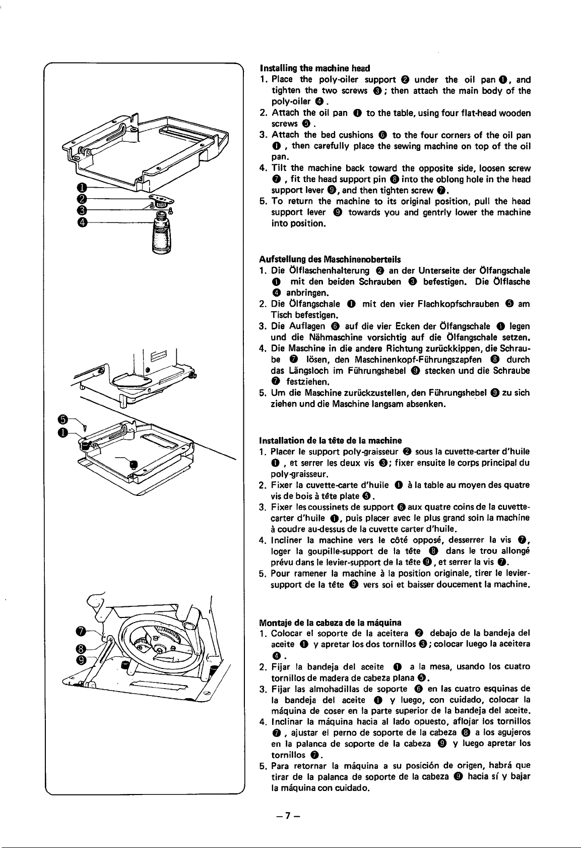
Installing
1. Place the
2. Attach
3.
4.
5.
Aufstellung des Maschinenoberteils
1. Die Olflaschenhalterung
the
machine head
poly-oiler support 8 under
tighten the two screws
poly-oiler e .
the
oil pan 0
screws
8.
Attach the bed cushions 0
0 , then carefully place
pan.
Tilt
the
machine back toward
0 ; then attach
to
the
table, using four flat-head wooden
to
the
the
sewing machine on
the
0 , fit the head support pin 0 into
0,
support lever
To
return
support
into position.
lever 0 towards you and gentrly lower
and then tighten screw
the
machine
to
f)
its original position, pull
an
der
the
oil pan
the
main body
four
corners
opposite side, loosen screw
the
oblong hole
f).
Unterseite der Olfangschale
of
top
the
0,
the
of
in
the
the
machine
0 mit den beiden Schrauben 0 befestigen. Die Olflasche
e anbringen.
2. Die Olfangschale
Tisch befestigen.
3.
Die Auflagen 0 auf die vier Ecken der Olfangschale 0 legen
und die Nahmaschine vorsichtig auf die Olfangschale setzen.
4. Die Maschine
be 0 losen, den Maschinenkopf-Fuhrungszapfen 0 durch
das Uingsloch
0 festziehen.
Urn
die Maschine zuruckzustellen, den Fiihrungshebel 0 zu sich
5.
ziehen und die Maschine
0 mit den vier Flachkopfschrauben 8
in
die andere Richtung zuruckkippen, die Schrau-
im
Fuhrungshebel 0 stecken und die Schraube
Iangsam absenken.
and
of
the
oil pan
the
oil
head
head
am
Installation
1. Placer
0 ,
poly-graisseur.
2.
Fixer
vis
3. Fixer lescoussinets de support 0 aux quatre coins de
carter d'huile
a coudre au-dessus de
4.
Incliner
loger
prevu
5. Pour ramener
support
Montaje
1. Colocar
aceite
de
Ia
tete
de
Ia
machine
le
support poly-graisseur
et
serrer
les
deux
vis
Ia
cuvette-carte d'huile 0 a
de
bois a
tete
plate
•.
0,
puis placer avec
Ia
cuvette carter d'huile.
Ia
machine vers
Ia
goupille-support de
dans
le
levier-support
Ia
machine a
de
Ia
tete
0 vers soi
de
Ia
cabeza
de
Ia
maquina
el
soporte de
Ia
aceitera 8 debajo de
0 y apretar los dos tornillos
f)
sous
Ia
cuvette-carter d'huile
0;
fixer ensuite
Ia
le
le
cOte oppose, desserrer
Ia
tete
de
Ia
tete
Ia
position originate, tirer
et
baisser doucement
le
table au moyen des quatre
plus grand soin
0 dans
0,
et
serrer
0;
colocar luego
corps principal du
Ia
cuvette-
Ia
machine
Ia
le
trou
Ia
vis
0.
le
Ia
machine.
Ia
bandeja del
Ia
aceitera
e.
2. Fijar
3.
4.
5. Para retornar
Ia
bandeja del aceite 0 a
tornillos
Fijar las almohadillas de soporte 0 en las cuatro esquinas de
Ia
maquina de coser en
I nclinar
f)
en
tornillos
tirar
Ia
de
madera
bandeja del aceite 0 y luego, con cuidado, colocar
Ia
maquina hacia
, ajustar
Ia
palanca de soporte de
de
cabeza plana
Ia
parte superior
al
el
perno de soporte de
0.
Ia
maquina a su posicion
de
Ia
palanca
maquina con cuidado.
de
soporte de
Ia
mesa, usando los cuatro
8.
de
Ia
bandeja del aceite.
I ado opuesto, aflojar los tornillos
Ia
cabeza 0 a los agujeros
Ia
cabeza 0 y fuego apretar los
de
origen, habra que
Ia
cabeza 0 hacia
si
vis
0,
allonge
levier-
y bajar
Ia
-7-
Page 12
·-
'--0
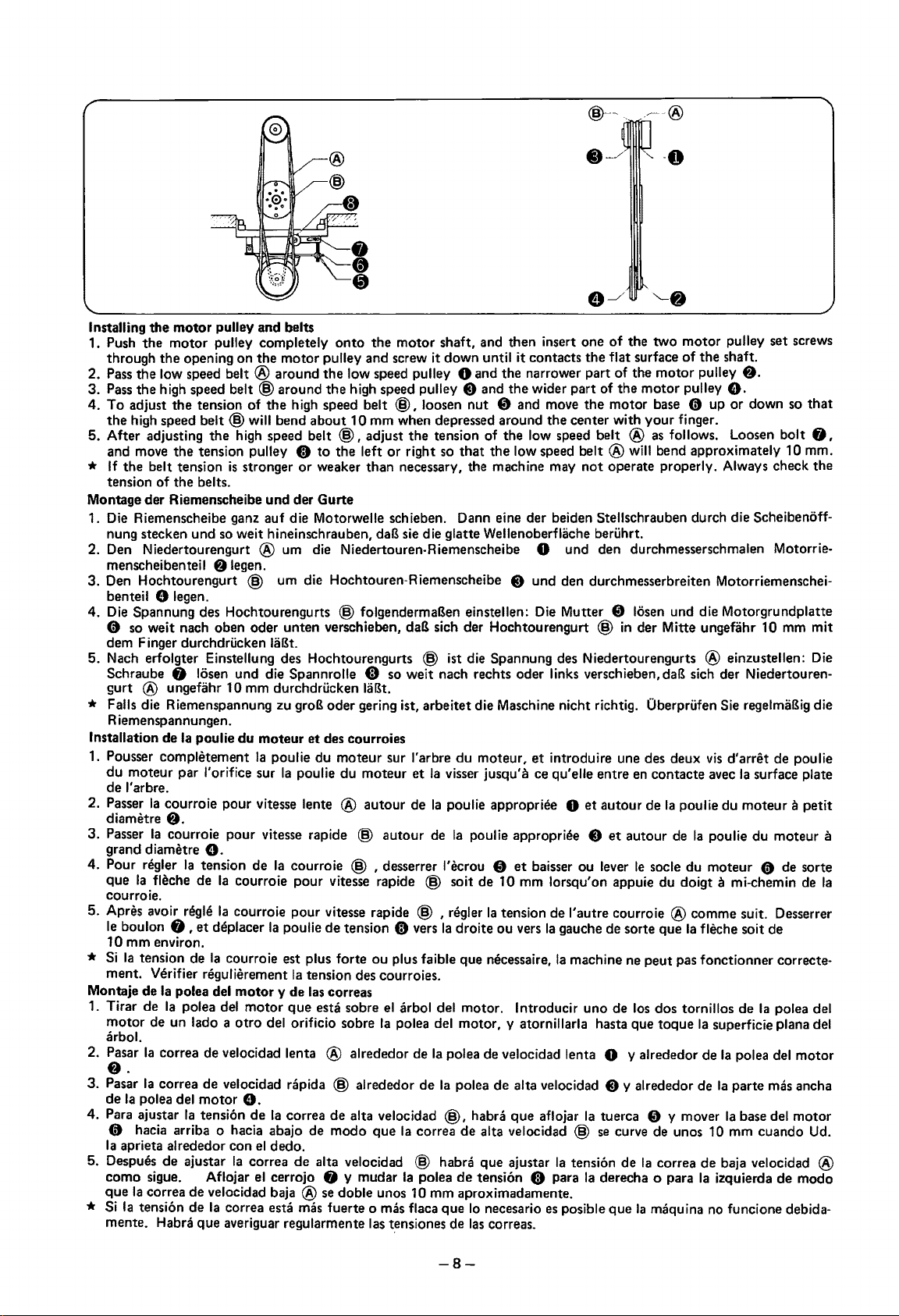
Installing the
1.
Push
through the opening on the
Pass
2.
3.
Pass
4.
To
the high
5.
After
and
*
If
the belt tension
tension
Montage der Riemenscheibe und der Gurte
1. Die Riemenscheibe
nung stecken und
Den
2.
menscheibenteil
3. Den Hochtourengurt
benteil
4. Die Spannung
0
dem Finger durchdrucken laBt.
5. Nach erfolgter Einstellung
Schraube 0 losen und die Spannrolle G
gurt ® ungefahr 10 mm durchdrucken laBt.
motor
the
the
low
the high
adjust the tension
speed
adjusting the high
move
of
Niedertourengurt ® urn die Niedertouren-Riemenscheibe 0 und den durchmesserschmalen Motorrie-
pulley and belts
motor
pulley completely
motor
speed
belt ® around the
speed
belt
@around
of
belt
the tension pulley 8
the belts.
the high
@will
bend about 10 mm when
speed
is
stronger
ganz
auf die Motorwelle schieben. Dann eine der beiden Stellschrauben durch die Scheibenoff-
so
weit hineinschrauben,
onto
the
motor
shaft,
and
then insert one
pulley and screw
low
speed
the high
speed
belt
to
or
weaker than necessary, the machine may
speed
belt
@,
adjust the tension
the
left
daB
it
down
until
it
pulley 0
pulley 8
@,
loosen
or
right
sie
die glatte Wellenoberflache beruhrt.
and
and
nut 8 and
depressed
so
of
that
the narrower part
the wider part
around the center
the
the
low
contacts the
move the
low
speed
speed
belt ®
belt
not
of
the
two
motor
flat
surface
of
the
of
the
motor
with
®will
operate properly. Always check the
of
the shaft.
motor
motor
your
pulley
pulley
base
0 up
finger.
as
follows. Loosen
bend approximately 10 mm.
8 legen.
@ urn die Hochtouren-Riemenscheibe 8 und den durchmesserbreiten Motorriemenschei-
0
legen.
des
so
weit
Hochtourengurts @ folgendermaBen einstellen: Die
nach oben oder unten verschieben,
des
Hochtourengurts @ ist die Spannung
daB
sich der Hochtourengurt @ in der
so
we
it
nach rechts oder links verschieben,
Mutter
des
8 losen und die Motorgrundplatte
Mitte
ungefahr 10 mm
Niedertourengurts ® einzustellen: Die
daB
sich der Niedertouren-
* Falls die Riemenspannung zu groB oder gering ist, arbeitet die Maschine nicht richtig. Oberprufen
R iemenspannungen.
Installation
1.
Pousser
du moteur par !'orifice sur
de
2.
Passer
diametre
3.
Passer
grand diametre e.
4. Pour regler
que
courroie.
Apres avoir regie
5.
le
10 mm environ.
*
Si
ment. Verifier
Montaje
1.
Tirar
motor
arbol.
2.
Pasar
8.
3.
Pasar
de
4.
Para
0 hacia arriba o hacia abajo
Ia
5.
Despues
como
que
* Si
mente.
de
Ia
poulie du moteur et
comph!tement
l'arbre.
Ia
courroie pour vitesse lente ® autour
Ia
poulie du moteur sur l'arbre du moteur, et introduire une
Ia
poulie du moteur et
8.
Ia
courroie pour
Ia
Ia
fleche de
boulon
Ia
tension
de
de
de
Ia
Ia
Ia
polea del
ajustar
aprieta alrededor con
sigue.
Ia
correa de velocidad baja ®
Ia
tension de
tension
0,
et deplacer
de
Ia
regulierement
Ia
polea del
Ia
polea del
un lado a
correa
de
correa
de
motor
Ia
tension de
de ajustar
Aflojar
Habra que averiguar regularmente
Ia
vitesse
de
Ia
Ia
courroie pour
Ia
courroie pour vitesse rapide @ , regler
courroie
motor
otro
velocidad lenta ® alrededor
velocidad rapida @ alrededor de
courroie @ , desserrer l'ecrou 8 et
Ia
poulie de tension 8
est
plus forte ou plus faible que
Ia
tension
y de
motor
que
del
orificio
0.
Ia
correa de alta velocidad
el
dedo.
Ia
correa de alta velocidad @ habra que ajustar
el
cerrojo 0 y mudar
correa
esta
mas
des
courroies
Ia
visser
jusqu'a
de
Ia
poulie
approprh~e
rapide @ auteur
vitesse
las
correas
esta
de
modo que
se
fuerte o
rapide @ soit
des
courroies.
sobre
el
sobre
Ia
doble unos 10 mm aproximadamente.
mas
las
de
Ia
poulie appropriee 8 et auteur
de
10 mm lorsqu'on appuie du
Ia
vers
Ia
arbol del motor. I ntroducir uno
polea del motor, y atornillarla
de
Ia
polea
Ia
@,
Ia
correa de alta velocidad @
Ia
polea de tension G para
flaca que lo necesario
t.ensiones
de
tension
droite ou
necessaire,
de
velocidad lenta 0 y alrededor
polea de alta velocidad 8 y alrededor
habra que aflojar
las
correas.
baisser
vers
ce
Ia
es
des
deux
qu'elle entre
0 et autour
ou lever
de
I' autre courroie ® comme suit. Desserrer
gauche
Ia
machine
Ia
Ia
tension
Ia
posible que
en
contacte
de
Ia
poulie du moteur a
de
Ia
le
socle du moteur 0
doigt
de
sorte que
ne
de
los
hasta
que toque
tuerca 8 y mover
se
curve
de
derecha o para
Ia
Ia
peut
pas
dos tornillos de
Ia
de
de
unos 10 mm cuando Ud.
Ia
correa de baja velocidad ®
Ia
maquina
fleche soit
fonctionner correcte-
de
pulley set
screws
8.
e.
or
down
so
that
bolt
0,
mit
Sie
regelmaBig die
vis
d'arret
de
poulie
avec
Ia
surface plate
petit
poulie du moteur a
de
de
Ia
polea del
mas
del
sorte
de
motor
ancha
motor
a mi-chemin
superficie plana del
Ia
polea del
Ia
parte
Ia
base
izquierda de modo
no
funcione debida-
Ia
-8-
Page 13
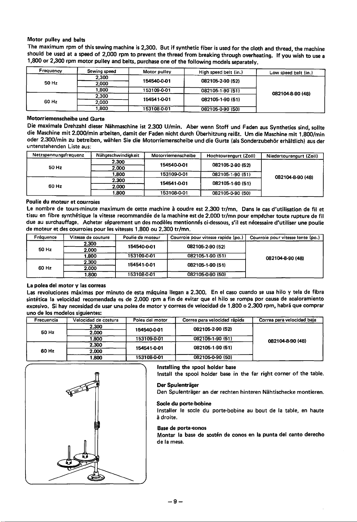
Motor pulley and belts
The maximum rpm of this sewing machine
at
should be used
1,800
or
2,300 rpm motor pulley and belts, purchase one
Frequency
50 Hz
60Hz
a speed
of
Sewing
2,300
2,000
1,800
2,300
2,000
1,800
2,000 rpm
speed
is
2,300. But if synthetic fiber
to
prevent the thread from breaking through overheating.
of
the
following models separately.
Motor
pulley
154540-0-01
1531 09-0-01
154541-0-01 082105-1-90
1
531
08-0-01
is
used for
High
speed
belt (in.)
082105-2-90
082105-1-90
0821 05-0-90 (50)
(52)
(51)
(51)
the
cloth and thread,
the
If
you wish
Low
speed
belt (in.)
082104-8-90 (48)
machine
to
use a
Motorriemenscheibe und Gurte
Die
maximale Drehzahl dieser Nahmaschine ist 2.300 U/min. Aber wenn Stoff und Faden aus Synthetics sind, sollte
die Maschine mit 2.000/min arbeiten, damit der Faden nicht durch Oberhitzung reiBt.
Urn
die Maschine mit 1.800/min
oder 2.300/min zu betreiben, wahlen Sie die Motorriemenscheibe und die Gurte (als Sonderzubehor erhaltlich) aus der
untenstehenden Liste aus:
Netzspannungsfrequenz
50
Hz
60Hz
Poulie du moteur
Le
nombre
et
courroies
de
tours-minute maximum de cette machine a coudre est 2.300 tr/mn. Dans
tissu en fibre synthE!tique
due au surchauffage. Acheter separement
et
de moteur
Frequence
50 Hz
60Hz
des courroies pour
Vitesse de couture
Niihgeschwindigkeit
2.300
2.000
1.800
2.300
2.000
1.800
Ia
vitesse recommandee
les
vitesses 1.800 ou 2.300 tr/mn.
2.300
2.000
1.800
2.300
2.000
1.800
Motorriemenscheibe
154540-0-01 082105-2-90
1531 09-0-01
154541-0-01
1
531
08-0-0 1
de
Ia
machine est de 2.000 tr/mn pour
un
des modeles mentionnes ci-dessous, s'il est necessaire d'utiliser une poulie
Poulie de moteur
154540-0-01 082105-2-90
1531 09-0-01 082105-1-90 (51)
154541-0-01
1
531
08-0-0 1 082105-0-90 (50)
Courroie pour vitesse rapide (po.)
082105-1-90
Hochtourengurt
082105-1-90
082105-1-90
082105-0-90 (50)
(52)
(51)
(Zoll)
(52)
(51)
(51)
Niedertourengurt (Zoll)
082104-8-90 (48)
le
cas d'utilisation
emp~cher
Courroie pour vitesse lente (po.)
toute rupture de
082104-8-90 (48)
de
fil
fil
et
La
polea del motor y
Las
revoluciones maximas por minuto de esta maquina llegan a 2.300.
sintetica
excesivo.
Ia
velocidad recomendada es de 2.000 rpm a fin de evitar que
Si
hay necesidad de usar una pole a
las
correas
de
motor y correas de velocidad de 1.800 o 2.300 rpm, habra que comprar
uno de los modelos siguientes:
Frecuencia Velocidad
50
Hz
60Hz
de
2.300
2.000
1.800
2.300
2.000
1.800
costura
Polea del
154540-0-01
motor
153109-0-01
154541-0-01
08-0-01
1531
Installing the spool holder base
Install
the
Spu lentriiger
Der
Den
Spulentriiger an der rechten hinteren Niihtischecke montieren.
Socle du porte-bobine
Installer
a droite.
Base
de porta-conos
Montar
de
Ia
Ia
mesa.
En
el
caso cuando
el
hilo
se
rompa por causa de acaloramiento
Correa para velocidad rapida Correa para velocidad baja
082105-2-90
082105-1-90
082105-1-90
082105-0-90 (50)
spool holder base
le
socle du porte-bobine au
(52)
(51)
(51)
in
base de sosten de conos en
se
usa
hilo y tela de fibra
0821 04-8-90 (48)
the far right corner
bout
de
Ia
table,
Ia
punta del canto derecho
of
the table.
en
haute
-9-
Page 14
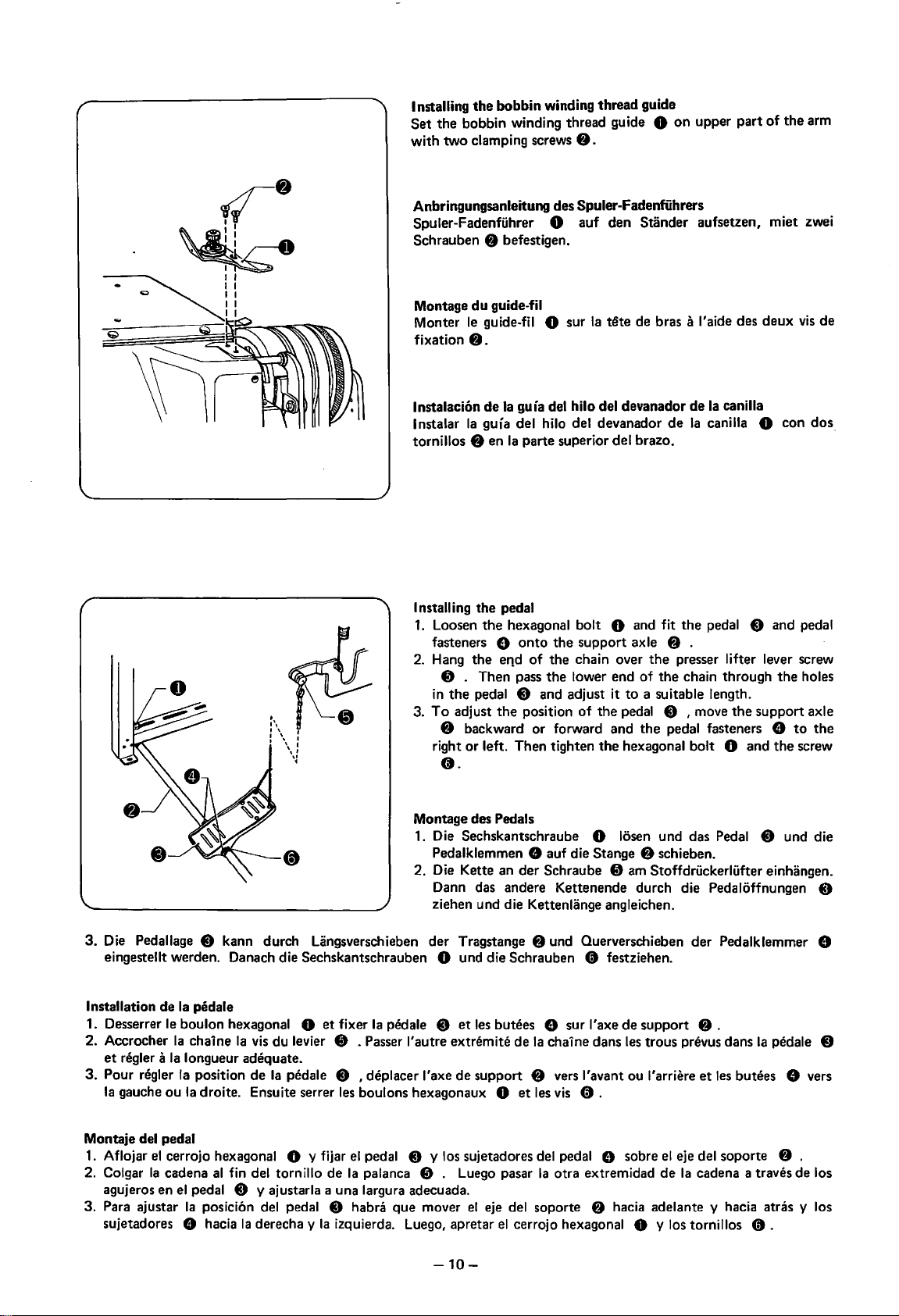
Installing
Set
with
the
bobbin
the
bobbin winding thread guide 0
two
clamping screws
winding thread guide
8.
on
upper
part
of
the
arm
Anbringungsanleitung des Spuler-Fadenfiihrers
Spuler-Fadenfuhrer 0 auf den Stander aufsetzen, miet zwei
Schrauben
8 befestigen.
•,
I,
I\
I \ I
I \ I
Montage
Monter
fixation
lnstalacion
lnstalar
tornillos 8 en
du
guide-til
le
guide-fil 0 sur
Ia
tete
8.
de
Ia
gula del hilo del devanador
Ia
guia del hilo del devanador
Ia
parte superior del brazo.
de bras a l'aide des
de
Ia
canilla
de
Ia
canilla 0 con
deux
vis
de
dos
Installing the pedal
1.
Loosen
fasteners
2. Hang
in
To
3.
I
\I
,,
~
right
the
hexagonal bolt 0 and fit
e
onto
the
e11d
of
8 . Then pass
the
pedal 0 and adjust it
adjust
the
position
• backward
or
left. Then tighten
or
o.
the
support
the
chain over
the
lower end
of
the
forward and
the
the
pedal 8 and pedal
axle • .
the
presser lifter lever screw
of
the
chain through
to
a suitable length.
pedal 0 I move
the
pedal fasteners e
the
support axle
hexagonal bolt 0 and
the
the
holes
to
screw
the
Montage des Pedals
1.
Die Sechskantschraube 0 losen und das Pedal 0 und die
Pedalklemmen
2. Die Kette an der Schraube
8 auf die Stange 8 schieben.
8 am Stoffdrlickerlufter einhangen.
Dann das andere Kettenende durch die Pedaloffnungen
ziehen und die Kettenlange angleichen.
3.
Die Pedallage 0 kann durch Langsverschieben
der
Tragstange 8 und Querverschieben
eingestellt werden. Danach die Sechskantschrauben 0 und die Schrauben 0 festziehen.
Installation
1. Desserrer le bouton hexagonal 0
2. Accrocher
et
3. Pour
Ia
de
regler a
Ia
regler
gauche ou
Ia
pedale
et
fixer
Ia
pedale 8
Ia
chaine
Ia
vis
du levier 8 . Passer l'autre extremite
longueur adequate.
Ia
position
Ia
droite. Ensuite serrer les boulons hexagonaux 0
de
Ia
pedale 0 I deplacer l'axe
et
les
butees 8 sur l'axe
de
Ia
chaine dans
de
support • vers !'avant ou l1arriere
et
les
vis
de
0 .
Montaje del pedal
1.
Aflojar
2. Colgar
agujeros en
3. Para ajustar
sujetadores
el
cerrojo hexagonal 0 y fijar
Ia
cadena
al
fin del tornillo
el
pedal 0 y ajustarla a una largura adecuada.
Ia
posicion del pedal 0 habra que mover
8 hacia
Ia
derecha y
el
pedal 8 y los sujetadores del pedal 8 sobre
de
Ia
palanca 8 . Luego pasar
Ia
izquierda. Luego, apretar
Ia
otra extremidad
el
eje del soporte 8 hacia adelante y hacia atras y los
el
cerrojo hexagonal 0 y los tornillos 0 .
-10-
der
support 8 .
les
trous prevus dans
et
el
eje del soporte 8 .
de
Ia
cadena a traves de los
Pedalklemmer 8
Ia
pedale 8
les
butees e vers
0
Page 15
Ill
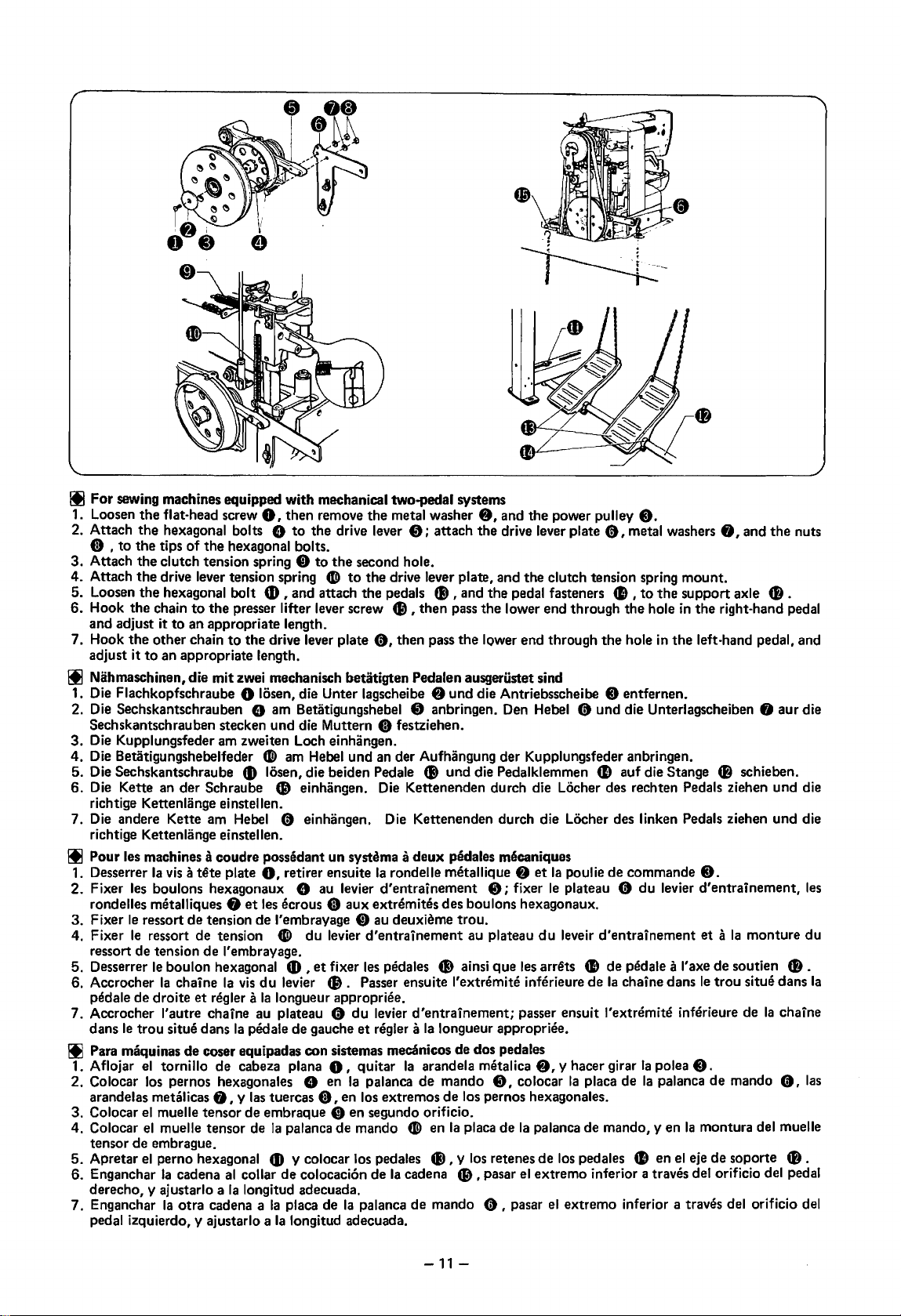
For
sewing machines equipped with mechanical two-pedal systems
1.
Loosen
2. Attach
0 ,
3.
Attach
4.
Attach
5. Loosen
6.
Hook
and adjust it to an appropriate length.
7. Hook
adjust it
the
flat-head screw
the
hexagonal bolts 9
to
the
tips
of
the
the
clutch tension spring 8
the
drive lever tension spring
the
hexagonal bolt
the
chain
to
the
the
other chain
to
an appropriate length.
0,
then remove
to
hexagonal bolts.
presser lifter lever screw Cl, then pass
to
the
the
to
tD,
and attach
drive lever plate
the
drive lever
the
second hole.
CD
to
the
the
metal washer
8;
attach
drive lever plate, and the clutch tension spring mount.
pedals
0,
fl),
then pass
8,
and
the
the
drive lever plate
and
the
pedal fasteners
the
lower end through
the
lower end through
power pulley C).
Ill Nihmaschinen, die mit zwei mechanisch betatigten Pedalen ausgerustet sind
1. Die Flachkopfschraube
2. Die Sechskantschrauben
Sechskantschrauben stecken und die Muttern
3.
Die Kupplungsfeder am zweiten Loch einhangen.
4.
Die Betatigungshebelfeder
5. Die Sechskantschraube
6.
Die Kette an der Schraube
richtige Kettenlange einstellen.
7. Die andere Kette am Hebel
richtige Kettenlange einstellen.
Ill Pour les machines a coudre possedant
1.
Desserrer
2.
Fixer
rondelles metalliques
3.
Fixer
4. Fixer
ressort de tension
5. Desserrer
6. Accrocher
pedale de droite
7. Accrocher l'autre chaine au plateau 0
dans
Ia
vis a tete
les
boulons hexagonaux 9 au levier
te
ressort de tension
le
ressort de tension
le
bouton hexagonal
Ia
chaine
le
trou
situe dans
0 losen, die Unter lagscheibe 8 und die Antriebsscheibe 8 entfernen.
9 am Betatigungshebel 8 anbringen. Den Hebel 0 und die Unterlagscheiben 8 aur die
C) festziehen.
CD
am Hebel und an der Aufhangung der Kupplungsfeder anbringen.
fD
losen, die beiden Pedale fl) und die Pedalklemmen
Cl
einhangen. Die Kettenenden durch die Locher des rechten Pedals ziehen und die
0 einhangen. Die Kettenenden durch die Locher des linken Pedals ziehen und die
un
plate
f)
de
J'embrayage.
Ia
et
regler a
systema a
0,
retirer ensuite
et
tes
ecrous 8 aux extremites des boulons hexagonaux.
de
l'embrayage 0 au deuxh!me
CD>
du
levier
tD
,
et
fixer
vis
Ia
pedale
du
levier
Ia
longueur
de
gauche
les
tl).
Passer ensuite l'extn!mite inferieure
appropril~e.
du
et
deux
pedales mecaniques
Ia
rondelle mthallique 8
d'entrainement
d'entrainement
pedales
levier
regler a
trou.
41)
ainsi que les arrets • de pedale a
d'entrainement;
Ia
longueur appropriee.
8;
fixer
au plateau
passer ensuit l'extremite inferieure de
et
Ia
le
du
Ill Para maquinas de coser equipadas con sistemas mecanicos de dos pedales
1. A flo jar
2. Colocar los pernos hexagonales 8 en
arandelas metalicas
3. Colocar
4. Colocar
tensor de embrague.
5.
Apretar
6. Enganchar
derecho, y ajustarlo a
7.
Enganchar
pedal izquierdo, y ajustarlo a
el
tornillo de cabeza plana
f),
y
las
tuercas
el
muelle tensor
el
muelle tensor de
el
perno hexagonal
Ia
cadena
Ia
otra cadena a
de
embraque ct en segundo orificio.
Ia
CD
al
collar
Ia
longitud adecuada.
Ia
0,
quitar
Ia
8,
palanca de mando
y colocar los pedales
de
colocaci6n
ptaca de
Ia
longitud adecuada.
palanca de mando
en los extremos
de
Ia
palanca
Ia
arandela metalica
de
los pernos hexagonales.
CD>
en
Ia
placa de
41),
Ia
cadena tl) , pasar
y los retenes
de
mando 0 , pasar
8,
8,
colocar
Ia
palanca de mando, y en
de
el
extreme inferior a traves del orificio del pedal
el
0,
metal washers
41,
to
the
the
hole
the
hole in
the
41
auf die Stange
poulie de commande
plateau 0
leveir d'entrainement
de
y hacer girar
Ia
placa de
los pedales
extreme inferior a traves del orificio del
du
Ia
chaine dans
Ia
polea
Ia
palanca
41
en
levier d'entrainement,
8,
and
support axle
in
the
right-hand pedal
left-hand pedal, and
CD
schieben.
8.
et a Ia
monture
I'
axe de soutien
le
trou
situe dans
Ia
8.
de
mando
Ia
montura del muelle
el
eje
de
soporte
the
CB.
CB.
chaine
0,
CB
nuts
Jes
du
Ia
las
.
-11-
Page 16

Installing
Fit
then
depressed.
Montage
Die Auflagen
stecken. Dann den Knopf
die
Installation
Mettre en place les coussins
Installer
f).
Montaje
Colocar las almohadillas
de
apretando
the
belt
cover
the
belt cover cushions 0
fit
the
belt cover gently over
des
Riemenschutzes
fur
den
Gurte
Jegen
und
aufsetzen.
du
couvercle des courroies
doucement
de
Ia
cubierta de correas
Ia
mesa y Juego instalar
el
bot6n
Riemenschutz 0
Je
couvercle
de
f)
into
f)
drucken
0 dans les
Ia
cubierta
con
cuidado
the
the
tout
holes in
belts while
und
trous
en
de
Ia
the
in
die Nahtischoffnungen
den Riemenschutz um
prevus
appuyant
correa 0 en los agujeros
cubierta sobre las correas
table
button
dans
sur
top,
Ia
le
bouton
and
f)
is
table.
Lubrication
• Everyday, before using
the
arrows. Fill
by
• Fill
the
liquid-cooled
Schmierung
• Taglich vor Arbeitsbeginn ein
zeichneten
• Den Kuhlbehalter ©
Huilage
•
Avant
aux endroits indiques par les fleches.
• Remplir le reservoir a refroidissement par liquide @ avec de l'huile silicone
Lubricacion
• Antes
que
• Llenar
Stellen auftragen. Und die Olbehalter ®
de
mettre
de
usar
Ia
indtcan
1as
el
dep6stito
flechas. No olvidarse
the
machine, apply
the
oil
tanks
® and @ also.
tank
© with silicon oil (100
oder
mit
Silikonol ( 100 CS)
Ia
machine en marche, appliquer une
maquina habra
refrigerado para l(quido ©
que
de
one
zwei Tropfen Nahmaschinenol
fUll
Ne
pas oublier
poner
una o
llenar
Ia
or
two
drops
of
machine oil (White Oil 70)
CS)
(WeiBol
und
@ fullen.
en.
ou
deux gouttes d'huile
de
remplir les reservoirs ®
dos
gotitas
de
aceite
de
charola del aceite ® y @ .
con
aceite de silicon (100 CS).
-12-
to
the
places indicated
Nr. 70) an den mit Pfeilen gekenn-
pour
machine a coudre (White
et
@.
(1
00 CS).
maquina (aceite blanco 70) en los
Oil
70)
puntos
Page 17

Probebetrieb
Die Maschine
1. Nach Einschalten
2.
Durch
dri.ickerfuB wieder ab.
3.
Das Pedal ganz niederdri.icken,
4.
Nachdem
dri.ickerfuB
• Niihmaschinen,
1.
Durch
Durch
2.
*
Achten
konnte
auf
folgende Weise anlassen:
des
Motors
teilweises Dru
die Maschine
ab,
Dri.icken des linken Pedals wird
Dri.icken
Sie
immer
.
cken
und
die Nahmaschine halt
die
mit
des
rechten
darauf,
Direction
Drehrichtu
Sens
zwei mechanisch
of rotat
ion
ng
de
rotation
drehen
sich die
des
Pedals
den
Stoffdri.ickerfuB
so
daB die Nahmaschine zu
eine
bestimmte
Pedals wird die Niihmaschine betiitigt.
daB
die Nahmaschine in
Stichzahl ausgefi.ihrt
an.
betiitigten
der Sto
Trial
Follow
1. When
operate
in
2. Depress
want
work
3.
Depress
When
4.
After
trimmed,
automatically.
•
For
systems
1. When
the
position.
2.
When
*
Operating
damage
right
Hocht
ouren-und Niedertouren-Riemenscheiben in Pfeilrichtung.
Pedalen ausgeriistet si
ffdri.ickerfuB
der
operation
the
procedure
the
power
and
the
the
direction shown
the
pedal
to
raise
the
clamp will
the
this
sewing a
sewing machines
the
pedal
the
it; al
direction.
absenken. lndem
arbeiten
abgehoben;
richtigen Dre
come
pedal
happens,
the
work
left pedal is depressed,
is
released,
right pedal
the
sewing
ways
beginnt.
hat,
wird
hrichtung lauft,
below
to start the
switch
high
work
fixed
is
turned
speed
and
low speed pulleys will revolve
by
the
arrow.
one
step
to lower the
clamp
again, release
up.
to
the
next
step
release
the
pedal
number
clamp
equipped
the
is
machine
make
Sie
Das Pedal rasch loslassen.
der
nd
beim Loslassen
of
will rise,
the
work
depressed,
sure
the
das
Pedal loslassen,
Faden
abgeschnitten,
da sie
machine
on
the
work
and
the
immediately.
stitches
and
the
with
mechanical
work
clamp
clamp
returns
the
sewing
in
the
wrong
machine
ste
llt
er
sonst
operating.
motor
will
start
clamp.
the
pedal
machine
the
thread
machine
is
to
machine
direction
is
running in
hebt
hebt
sich wieder zuri.ick.
beschadigt
If
and
will
start.
will be
will
two-pedal
raised; wh
its original
starts.
der
Stoff-
der
Stoff-
werden
you
the
stop
en
can
the
to
de
Ia
Essai
Proceder
1. Lorsque
par
2.
Appuyer
de-biche a sa
3.
Appuyer
immediatement.
4.
Apres
s'
*
Pour
1.
Lorsque l
retourne
2.
Lorsque
* Si l
Ia
Prueba
Proceder
1.
Cuando
2.
Apretar
3.
Luego,
mente
4. Despues
* Para
1.
Cuando
a su posicion original.
2.
Cuando
machine
comme
le
Ia
fhkhe.
sur
sur
qu'un
arretera.
les machines a
'on
a sa
I'
on
'on fait
machin
e elle-meme; s'assurer
de
operacion
de
Ia
el
el
apretar
.
de
maquinas
se pisa el pedal i
se pisa el pedal
moteur
Ia
position
Ia pedale
certain
appu
position
app
fonctionner
manera
motor
pedal para
un
* El funcionamie
s
iempre
de
que
suit.
est
pedale
nombre
coudre
ie
sur
uie s
ur
indicada abajo .
esta
bajar el pie-prensor. Para
un
poco
cierto
numero
de
coser
nto
de
esta
se mueve
mis
en marche
jusqu'au
initiale.
jusqu'au deuxieme
d'origine.
Ia pedale
Ia
funcionando
mas
equipadas
derecho,
Ia
premier
de
points
possedant
Ia pedale
machine a coudre
el
de
zquierdo,
maquina
en
un
de gauch
de
droite,
done
que
las poleas
pedal y
puntadas,
con
el pie del prensatelas se eleva,
empieza a funcionar
de
el
sentido
les poulies
cran
pour
cran pour
ont
ete
cousus, le fil sera
systeme a deux
e,
le pied-presse
Ia machine a
dans
Ia
machine
de
velocidad rapida y l
que
Ia
maquina
el
hilo
sistemas
coser
mecanicos
en
sen
correcto.
pour
vitesse
lente
et
vitesse rapide
baisser
le
pied-de-biche. Reliicher
mettre
Ia mauvaise
fonctionne
el
mismo
comenzara a funcionar. No
es
cortado
tido
Ia
machine
coupe,
pedales mecaniques
ur
s'eh~ve;
coud
re se
met
direction,
toujours dans
dos
enta
pedales
de
coser.
puede
vuelva a su posicion
, el pie-prensor se l
de
Ia
maquina
inverso
en marche. Dans ce cas, reliicher
lorsqu'on
en
giran hacia Ia
cuando
causar deterioros
tourneront
Ia
pedale
le pied-de-biche se relevera
relache Ia
marche.
il
peut
en
res
ulter
Ia
bonne
direction.
direccion que indica
de
origen
olvidarse de liberar el pedal
evanta y Ia
se suelta el pedal, el
dans
pour
pedale,
des
habra
maquina
en
Ia
dommages
que
prensat
maquina;
le
sens indique
ramener
le pied-presseur
liberar el
deja
Ia
et
Ia
machine
causes a
Ia
inmediata
de
funcionar.
elas vuelve
asegurese
le
pedale
flecha.
peda
pied-
l.
·
-13-
Page 18

Checking
Proceed through
operation
1.
2. With
3. Release
Oberpriifung des Nahmaschinenbetriebs
Auf
schinenbetrieb uberprufen.
1. Die Maschine
2.
3.
the
basic
operation
the
of
the
With
the
machine in
of
the
arrow.
approximate
the
drive lever 0 held in
clutch.
the
nachstehende Weise die Maschine so einstellen, daB sie von Hand ausgedreht werden kann. Danach den·--Nahma-
Pfeilrichtung drehen. Der StoffdruckerfuB wird abgesenkt
Rollenmitte 8 ausgerichtet.
Den Steuerhebel 0 in der Hochstellung halten
abheben.
Den Steuerhebel 0 loslassen, die Scheibe urn ungefahr
following steps
machine.
The
center
drive lever 0 ,
steht
of
the
machine
the
stop
position
work clamp will
of
the
roller 8 .
the
turn
in
der
Ruheposition, und
to
adjust
the
machine so
and
the
drive lever 0 raised,
come
down,
and
raised position, lower
the
pulley
about
der
und
that
it can be
the
groove ®
the
power actuating lever 8 completely
90
degrees, and
Steuerhebel 0 ist hochgezogen. Die Antriebsscheibe
und
die Nut ® des
durch
Senken des Einschalthebels 8 die Kupplung ganz
90°
drehen und dann
rotate
on
then
turned
by hand. Then check
the
power pulley
the
power cam will be aligned with
release
the
power
Steuernocken
den
Einschalthebel 8 freigeben.
fJ
in
actuating lever 8 .
ungefafr
the
the
direction
to
raise
mit
basic
the
fJ
der
the
in
Verification des fonctions
Proceder
fonctions
1.
2. Avec
3. Relacher le levier
Comprobacion
Siga estas indicaciones a fin
maquina.
1. Estando
2. Con
3.
comme
de
La
machine
de
sens
approximatif
le
l'embrayage.
seta.
El
mado
del rodillo 8 .
Ia
embrague.
Liberar
suit pour regler
base.
etant
Ia
fleche. Le pied-de-biche s'abaissera,
de
levier
d'entrainement
de
Ia
Ia
maquina parada y
pie prensor baja y
palanca
Ia
palanca
de
a l'arret
Ia
piece cylindrique 8 .
d'entrainement
operacion basica
de
comando
de
comando
base
Ia
et
le levier
machine
pour
le
fonctionnement
d'entrainement
et
Ia
rainure ® sur
0 leve, faire
0 maintenu en position levee, baisser
0 ,
de
ajustar
con
Ia
ranura ®
de
Ia
Ia
Ia
palanca
tourner
Ia
poulie d'environ
maquina.
maquina para
de
comando
que
se encuentra sobre
el
uso manual. Y luego, verifique
0 alzada, hacer girar
0 sostenida en posicion alzada, bajar
0 , girar
Ia
polea unos
90
grados y luego liberar
manuel.
tourner
Ia
came
le
levier
90°,
puis relacher
Ia
leva
de
completamente
Cette
condition
Ia
poulie
de
de
commande
de
commande 8 a fond
le
levier
Ia
Ia
polea 8 hacia
comando
Ia
palanca
se alinea
Ia
palanca 8 para alzar
de
remplie, verifier les
commande
s'alignera avec le
de
commande
operaci6n basica de
con
comando
Ia
direcci6n
el
centro
0 .
8 dans le
centre
pour
8.
aproxi-
lever
Ia
de
Ia
el
-14-
Page 19

Basic
operation
When
the
contact
part
disengages again,
cam
With
with
clamp rises. Finally,
from
Arbeitsweise des Stoffdruckerliifters
Wenn
der
des Kupplungdaumens
und wieder abhebt, lost sich
brochen wird. Wahrend sich
driickerfull
Beim letzten Stich ruckt die Rolle
mit
Rolle (1). Durch diese Drehung
die
u nterbrochen.
with
® will
part ® rotates
the
power
power
der
Steuernocken 8 mit
der
Antriebsscheibe 0
Rolle (I) berUhrt
of
the
power
presser lifter
drive lever 0 is raised, roller
the
power
pulley 0 . When this happens power will be
rotate
up
to
the
position
power
cam 8 will disengage from
from
roller
(I)
final stitch, roller (II) disengages and moves downwards
pulley 0
pulley 0 .
Steuerhebel 0 angehoben wird, wird die Rolle (I) ausgerastet
abgesenkt.
and
clutch
the
power
is
der Antriebsscheibe 0
dreht
sich zur Rolle (II).
der
der
Teil ® des Kupplungdaumens von
in
Beriihrung,
hebt
und
sich
der
(I)
will disengage and move upwards
transmitted
of
roller (II}.
to
roller (II)
cam
part
cut
off
Steuernocken
(II)
aus
der Stoffdruckerfull ab. lndem schlielllich der Teil @ des Kupplungdaumens
Steuernocken
the
® rotates from roller (II)
when
und
bewegt sich nach
und
Then,
when clutch cam
the
power
pulley 0 and
work
clamp
comes
down.
and,
as
to
clutch
cam
part ® contacts
und
in
Beriihrung, so dall Kraft iibertragen werden kann. Der Teil ®
Sebald
8 von
der
der
Teil @ des Kupplungdaumens gegen die Rolle (II) stollt
der
Antriebsscheibe 0 , so dall die Kraftiibertragung
der
Rolle (I) zur Rolle (II)
unten.
Teil ® des Kupplungdaumens
8 von
der
Antriebsscheibe 0 lost, wird die Kraftubertragung
Wie
and
power cam 8 will move
to
power cam 8 ,
part
® pushes against roller (II)
the
power will be
before, power cam 8 moves
roller, (I). During this
roller
(I)
and
power
nach
oben
gezogen.
zuvor,
kommt
der
Steuernocken
dreht
sich von der Rolle (II) zur
and
cut
off. While clutch
movement
cam 8 disengages
In
der Folge
dreht,
wird
clutch cam
into
contact
the
kommt
unter·
der
Stoff-
8 nun
int:>
and
work
Fonction
Lorsque
8
Ia
cylindrique (II). Ouand
degagera
coupee.
le
pied-de-biche descend.
Lors
8 se
cylindrique (I) a
coupee
se degage
Operacion basica
Cuando
8
8 y una parte ®
® hace presion sobre
y
Ia
Con
contacto
ejecuta este movimiento,
embrague ®
de
base
du
releveur
le
levier
de
commande
entrera
came
alimantaci6n se corta. Mientras
Ia
en
de
commande 8 et
de
nouveau,
Pendant
du
dernier
met
en
lorsque
de
Ia
Ia
palanca
entra
en
contacto
ultima
con
Ia
contact
point,
contact
Ia
poulie
dellevantador
puntada,
polea
entra
avec
Ia
que
Ia
partie ®
Ia
avec
Ia
piece cylindrique (II).
partie ®
de
commande
de
comando
con
de
Ia
el
el
de
en
contacto
du
presseur
0 est leve,
Ia
poulie de
Ia
partie @
Ia
partie @ mentionnee plus
came
de
commande 8 se
de
piece cylindrique (II) se degage
Ia
poulie
de
Ia
came
Ia
piece cylindrique (I) se degagera
commande
de
Ia
came
Ia
came
d'embrayage
de
commande 0 et
Pendant
d'embrayage
0 . Cette
d'embrayage
haut
degagera
ce
mouvement
touche
8 .
del prensor
0 esta levantada,
Ia
polea
de
leva
de
embrague gira hasta
rodillo
(II)
rodillo
energia 0 y
el
(II)
pie prensor se levanta. Finalmente,
con
de
energia
el
rodillo (I)
energia 0 .
y se Iibera
Ia
parte
de
se Iibera y se mueve hacia abajo y,
Ia
parte
el
rodillo (I) y
Ia
de
de
Cuando
Ia
posicion del rodillo (II). Luego,
nuevo;
leva
de
embrague @ gira del rodillo
Ia
leva
Ia
leva
et
se levera
condition
tournera
exercera une pression sur
de
Ia
poulie
tourne
de
Ia
et
descend et,
Ia
partie @
le
pied-de-biche remonte. Enfin, !'alimentation est
Ia
piece cylindrique (I)
se
Iibera y se mueve hacia arriba y
esto
sucede
Ia
leva
de
comando
como
de
embrague ® gira del rodillo (II) hacia
Ia
alimentaci6n
de
comando 8 se
remplie
jusqu'a atteindre
de
piece cylindrique (I) a
comme
de
Ia
Ia
energia es transmitida a
8 se suelta
antes,
suelta de
le
mouvement
Ia
piece cylindrique (II)
commande 0 et
auparavant,
came
d'embrayage
et
Ia
Ia
parte
de
(I)
al
(II)
Ia
leva
de
se
corta
cuando
Ia
polea
et
Ia
came
de
commande
sera transmis a
Ia
position
!'alimentation sera
Ia
piece cylindrique (II)
Ia
came de
came
de
Ia
Ia
de
Ia
Ia
polea
el
pie baja.
comando
Ia
de
comando
de
commande
tourne
de
commande
leva
de
leva
de
leva
de
de
energia 8
8 se
el
(1). Mientras se
parte
de
Ia
piece
et
se
Ia
piece
8
comando
comando
embrague
pone
en
Ia
leva de
8
-15-
Page 20

..
~------;------
(
..
,
,:_!~
I I
\ :
··~
\ i
"'~
,~--.
.
'',
\ i
-/'".
··-....;,
. ../
------
---~
~
i
Basic operation
• When
tension disc
main tension disc closes. While sewing
final stitch
releases.
• The
outer
whether
of
cam part ©, and
the
moving blade operates,
8 momentarily increases
when trimmed. Thus,
Arbeitsweise
• lm Maschinenstillstand
ist. Wenn die Maschine zu arbeiten beginnt, ruckt
scheibe schlieBt. Wahrend des Nahens wird
letzten Stich
scheibe
• Die AuBenfeder an der Nebenspannscheibe ubt immer einen leichten Druck auf den Oberfaden aus - unabhangig
davon,
Kurventeil
Spannungslosestift zuruckt vor dem Fadenabschneiden zum Kurventeil @ , so daB die Spannungslosescheibe 8
kurzzeitig den Druck
verhindert.
Fonction
• Ouand
et
les disques du tendeur principal
pimetre
fil
de
monte
•
Le
ressort exterieur
de
ou
partie ©
!'action de
tension 8 tend
Ainsi
Operacion
• Cuando
el
disco
y
0 penetra en
superior es mantenida. Con
hacia
•
El
muelle exterior del disco de tension auxiliar provee una tension poco resistente
maquina esta o no cosiendo.
de
Ia
se ajusta y, antes
leva y
hilo salga
of
the
upper tension discs
the
machine
the
spring
the
der
offnet
ob
die Maschine naht oder stillsteht. Der Spannungslosestift 8 der Nebenspannscheibe befindet sich am
Auf
de
base des tendeurs de fil
Ia
machine est a l'arret,
Ia
partie @
dessus sera maintenue. Lors du dernier
jusqu'a
l'arret
de
Ia
le
bout
basica de los discos
Ia
maquina esta parada,
de
Ia
parte ®
leva
de
el
disco 8 de liberacion
de
is
at
a standstill,
is
released. When
clutch engages,
of
the
auxiliary tension disc always supplies weak tension
machine
oberen
ruckt die Kupplung ein: Der Spannungslosestift 0 ruckt zum Kurventeil @ , und die Hauptspann-
sich.
is
sewing
the
tension releasing disc 8
the
the
the
remaining
Spannscheiben
steht
der Spannungslosestift 0
© , und die Spannungslosescheibe 8
auf
den Oberfaden verstarkt und die Fadenabnahme von
diese Weise wird der Faden immer im gleiche Abstand von
de
Ia
came,
Ia
partie ® de
du
tendeur
de
Ia
machine.
Ia
came,
et
le
disque
lame,
Ia
goupille de relachement
momentanement
restant
du
fil est toujours
de
tension principal
Ia
parte @
el
de
Ia
leva y
comando © y
que
Ia
bobina cuando
el
Ia
cuchilla movible funcione,
the
tension releasing pin 0
the
machine starts,
the
the
tension releasing pin 0 moves
or
not.
The
tension releasing pin 8 moves into cam
tension
Ia
goupille
Ia
came
de
La
tension superior
el
se
de
ultimo
el
disco
El
perno
disco 8
de
el
mismo es ribeteado.
on
end
of
de
sont
ouverts. Ouand
et
les
disques
et
les disques
fil
auxiliaire
goupille
abre. Cuando
Ia
de
de
tension 8 est libre. Lors
Ia
tension du
d'une
perno
de
leva, y
el
punta
de
tension principal
de
liberacion
de
presion au menta momentaneamente
the
tension releasing pin 0 moves into cam
disc always supplies adequate tension
tension releasing pin 8
is
floating. With
the
upper
thread
thread from
der
auf
relachement
du
point
tend
rehichement
de
tension 8
fil
longueur uniforme.
liberacion
Ia
disco
el
embrague
liberacion de presion queda flotando. Con
the
am
Spannungslosestift zum Kurventeil @ , und die Hauptspann-
den Oberfaden stets ein ausreichender Druck ausgeubt. Beim
dreht
de
Ia
machine est mise en marche,
tendeur
l'embrayage s'engage,
du
tendeur principal s'ouvrent.
legerement
de
superieur
de
tension 0 esta en
maquina empieza a funcionar,
de
tension principal
se
se
de
tension 8 del disco auxiliar de tension esta
el
perno de liberacion
is
to
prevent it from being drawn
needle
Kurventeil ® , so daB die Hauptspannscheibe
sich. Beim letzten Stich ruckt die Kupplung ein,
tension 0 est a
principal
le
tension 8 du
du
se
loge dans
pour
l'empecher
ajusta,
abre.
at
the
position
up
to
cam
of
the
auxiliary tension disc
the
final stitch
part
is
always
der
Ia
se
referment. Pendant
fil
de
dessus independamment
tendeur
dernier.
Ia
se
cierra. Mientras se cose,
el
perno de liberacion
de
tension 8
Ia
tension del hila superior para evitar
of
cam part ® and
to
the
upper thread. With
part
®,
and
the
to
the
upper thread, irrespective
the
clutch engages and, before
@ and
cut
der
Nadel abgeschnitten.
position
Ia
goupille
point
partie @ de
de
se
Ia
posicion de
el
al
the
tension releasing disc
out
to
a uniform length.
Spule wahrend des Abschneidens
de
Ia
partie @
Ia
goupille de relachement 0
Ia
couture
de
relachement
de
fil
auxiliaire se trouve a
l'embrayage s'engage
Ia
came
debobiner
perno
hilo superior sin considerar
el
Ia
de
de
ultimo
entra
quand
parte ®
liberacion
presion 0
en
part
main tension disc
is
at
from
Ia
de
et
il
Ia
tension del hilo
en
punta
Ia
parte @ de
the
main
@,
and
the
the
position
the
spool
often
de
Ia
came
tension du
de
tension
Ia
marche
et,
avant
le
disque
sera coupe.
de
Ia
leva
de
tension
se
mueve
si
Ia
posicion
el
embrague
que
the
of
der
Ia
de
Ia
Ia
el
-16-
Page 21

[Figure
A]
[Abbildung
[Figure
A]
[Figura
A]
A]
[Figure B)
[Abbildung
[Figure B)
[Figura B)
B)
[Figure
C)
[Abbildung
[Figure C)
C)
[Figura
C)
Basic operation
When
the
Figure A, and
to
the
position shown
low speed. This
presser plate
0 , and high speed sewing begins. When stitching
disc
presser plate
of
stopping and preserves
of
the
clutch
machine
is
at
a standstill
the
high speed pulley 8 and
in
Figure 8
is
to
prevent
f)
then
moves
f)
moves
to
the
the
the
steel ball 0 and
the
low speed pulley 8 are idling. When
the
low speed pulley 8 presses against
the
thread from slipping
to
the
position shown in Figure C,
position shown
in
excellent durability
the
ball presser plate
out
of
the
is
completed up
stop
needle
at
the
high speed pulley 8 presses against
to
f)
are
the
cam 8 and
the
commencement
the
fourth
in
the
positions shown
ball presser plate
two
stitches are sewn at
of
sewing.
stitch from
the
end,
Figure 8 and slow speed sewing begins again. This eases
of
the
sewing machine.
f)
The
the
the
moves
clutch
the
shock
ball
ball
Arbeitsweise der Kupplung
Maschinenstillstand liegen die Stahlkugel 0 und die Kugeldruckplatte
lm
Hochtourengezeigte
Stiche
der Nadel schlupfen. Danach
riemenscheibe 8 driickt gegen die Kupplungsscheibe 0 ,
nahen. Vier
8 und Niedertouren-Riemenscheibe 0 Iauten leer. Wenn die Kugeldruckplatte
Stellung ri.ickt, wird die Niedertouren-Riemenscheibe 8 gegen den
mit
geringer Nahgeschwindigkeit ausgefi.ihrt werden. Dadurch kann der Faden beim Nahbeginn
ruckt die Kugeldruckplatte
Stiche vor Nahtende ruckt die Kugeldruckplatte
f)
in
die
und
die Maschine beginnt
f)
in
in
Abb. C dargestellte Position: Die Hochtouren-
die in Abb. 8 gezeigte Stellung, so
f)
, wie in Abb. A dargestellt. Die
f)
,
in
die
Sperrnocken
8 gedri.ickt, so daB zwei
nicht
mit
groBer Geschwindigkeit zu
daB
in
Abb. 8
mehr
aus
die letzten
Stiche wieder Iangsam ausgefiihrt werden. Auf diese Weise wird die Lebensdauer der Nahmaschine wesentlich verlangert,
nicht
weil die Maschine
Fonction
Ouand
Ia
deplace
sont
pression
d'embrayage
comme
abilite
de
base
Ia
machine est a l'arret,
figure A,
et
les poulies
comme
cousus a vitesse lente. Cela a
f)
se
deplace alors
0
montre
de
Ia
machine.
plotzlich angehalten wird.
de
l'embrayage
Ia
pour
montre
sur
Ia
figure
comme
et
Ia
sur
couture
Ia
figure 8
a vitesse rapide commence. Ouatre points fin,
et
bille d'acier 0
vitesse rapide 8
8,
Ia
poulie
pour
but
d'empecher
Ia
couture
montre
sur
a vitesse lente reprend. Ceci
et
Ia
plaque
de
et
vitese lente 8
pour
vitesse lente 8 presse
le
fil
de se glisser hors
Ia
figure C,
Ia
poulie
pression
sont
pour
f)
se
trouvent
libres. Ouand
contre
de
dans
Ia
plaque de pression
Ia
came
d'arret 8 et
l'aiguille au
vitesse rapide 8 presse
Ia
amortit
plaque
le
choc
de
de
pression
I'
Ia
position
debut.
arret
contre
et
preserve
montree
deux
La
plaque de
le disque
f)
se
sur
f)
se
points
deplace
Ia
dur-
in
Operacion fundamental del embrague
Ia
Cuando
maquna
posicion indicada
minima.
velocidad
que
indica
Cuando
8 hace presion sobre
el
hilo
se
Ia
figura
empieza a coser a alta velocidad. Cuando se term ina
Ia
bola
f)
se
choque
el
de
no
esta funcionando
en
Ia
figura
Ia
plancha prensora
escape
de
Ia
aguja
C,
Ia
polea
de
mueve hacia
Ia
parada y conserva
Ia
bola
de
A, y Ia
polea
de
Ia
leva
de
at
comenzar a coser.
acero 0 y
de
alta velocidad 8 y
Ia
bola
f)
se
mueve a
parada 0 y
La
dos
Ia
puntos
plancha prensora
alta velocidad 8 hace presion sabre
Ia
costura hasta
posicion indicada en
Ia
excelente durabilidad
Ia
Figura 8 y
de
Ia
maquina.
el
plancha prensora
Ia
polea
de
baja velocidad 8 estan
Ia
posicion indicada en
son cosidos a velocidad baja. Eso sirve para evitar
de
el
disco
de
el
cuarto
punta
coser a velocidad baja empieza
-17-
de
Ia
Ia
bola 8
embrague 0
desde
elfin,
bola
Ia
se
figura
f)
se
encuentra
funcionando
8,
Ia
polea de baja
mueve a
yen
Ia
posicion
seguida
Ia
plancha prensora de
otra
Ia
vez. Eso suaviza
en
Ia
en
que
maquina
Page 22

J
Basic operation
When
the
the
moving blade moves
moving blade take-in 8 matches
blade take-in
thread loop, and returns again
Before
the
Arbeitsweise des
lm Maschinenstillstand steht das bewegliche Messer
sich das Messer
bis die Messerkante
fadenschleife
Bevor die Kupplung einruckt und
Fonction
Lorsque
commence
position pour laquelle
se deplace
Lors
de
position
Avant que l'embrayage ne soit engage
Operaci6n fundamental
AI
parar
a moverse hacia abajo,
posicion en
Ia
aguja
8 coincide con
vuelta del hilo superior y retorna
Antes
que
of
the
moving blade
sewing machine
8 matches
clutch
is
beweglichen Messers
in
Pfeilrichtung bis die Messerkante 8 am Stichplattenloch ® steht. Das Messer 0 bewegt sich weiter
is
stopped,
in
the
the
to
engaged and
direction indicated by
the
needle-plate take-in
the
the
8 am Stichplattenloch @ steht. Beim letzten Stich fangt das bewegliche Messer 0 die Ober-
und
kehrt
wieder zum Stichplattenloch ® zuriick.
der
de
base
de
Ia
lame mobile
Ia
machine a coudre est arretee,
a s'abaisser,
a nouveau,
Ia
formation
de
Ia
prise
Ia
maquina
Ia
que
@.
La
el
embrague empiece a funcionar y
Ia
tige mobile se deplace dans
Ia
prise
de
Ia
de
sorte
que
du
dernier point,
du
plateau a
de
de
coser,
Ia
el
movimiento hacia atras
cuchilla movible 0 se mueve
el
mismo movimiento
aiguille@.
Ia
cuchilla movible
Ia
cuchilla movible esta en su posicion
cuchilla movible se mueve en
otra
the
moving blade
needle plate take-in
needle plate take-in
work clamp
Stoffdruckerfuf! abhebt, schneidet das Messer 0 den Faden durch.
tige mobile 8 se synchronise avec
Ia
prise
Ia
et
que
de
vez hacia
is
Ia
tige mobile se trouve a sa position
de
Ia
tige mobile 0 garde
le
pied-presseur ne
de
Ia
de
Ia
placa
Ia
el
pie del prensatelas
is
in its rest position. When
the
arrow, and
®.
@.
At
the
position®.
raised,
the
moving blade 0
in
der
Ruhestellung. Beim Absenken des Stoffdriickerfuf!es bewegt
Ia
direction indiquee par
tige mobile 8 se synchronise avec
Ia
direccion indicada por
cuchilla movible 8 coincide con
nuevo,
de
forma
de
Ia
aguja @. En
marca ® en
Ia
is
returned forcefully
The
moving blade 0 moves again, so
final stitch, the moving blade 0 scoops
cuts
the
de
Ia
fh!che,
Ia
prise du plateau a aiguille
Ia
boucle du
se
reh!ve,
de
descanso. Cuando
que
el movimiento hacia atras
Ia
placa
de
se
levante,
fil
superieur
Ia
tige mobile 0 coupe
Ia
el
ultima puntada,
aguja. ·
Ia
cuchilla movible 0 corta
the
work clamp begins
to
the
position where
thread.
repos. Lorsque
et
est ramenee
®.
Ia
prise
du
plateau a
et
retourne a nouveau a
le
fil.
el
pie del prensatelas empieza
flecha y vuelve forzosamente a
mismo movimiento
de
Ia
Ia
cuchilla movible 0
to
lower,
that
the
moving
up
the
upper
le
pied-presseur
de
force a
La
tige mobile
aiguille@.
de
Ia
placa
cuchilla movible
toma
el
hilo.
the
Ia
Ia
Ia
de
Ia
Installing
Loosen
the
tighten set screw
Nadelbefestigung
Die
Nut zu
Danach die
Mise
Desserrer
vers l'avant, enfoncer complement
Montaje
Aflojar
encastre prolongado quede volteado hacia frente. Apretarla com-
pletamente hasta que llegue
the needle
screw
0 , hold
front, push it
the
in
completely until it hits
0 .
Schraube 0 losen. Die Nadel 8 so halten,
Ihnen schaut, und bis zum Anschlag ganz hineinstecken.
Stellschraube 0 festziehen.
en place de l'aiguille
Ia
vis
0 , tenir l'aiguille
de
Ia
aguja
el
tornillo 0 , coger
-18-
needle 8 with
f)
avec
et
resserrer
Ia
aguja
f)
al
fin y luego apretar
the
long groove facing
the
end, and then
daB
die lange
Ia
rainure longue
Ia
vis
0 .
de manera que
el
tornillo 0 .
el
Page 23

Upper threading
Thread
E
the
infideln
upper
des Oberfadens
Den Oberfaden, wie
Enfilage superieur
Enfiler
le
fil
de
dessus
Hilo superior
Enhebrar
el
hilo superior correctamente
[Cotton
thread]
Baumwollzwirn]
[
[Fil
de
coton]
[Hilo
de algod6n]
thread
correctly as shown below.
unten
gezeigt, einfadeln.
correctement
com me indique ci-dessous.
como
se
muestra abajo.
[Synthetic
[Syntheticsfaden]
[ F
il
[Hilo
thread]
synthetique J
sintthico]
Selecting a needle and
The
type
of
needle and
to
the
type
of
sewing
guide
to
their
selection.
Needle Thread Type
DP
X 5
#9
Dp
X 5
#14
DP
X 17
#19
Aiguille
Le
couture
choix
Aiguille
DPx5
DPx5
·DPx17
et
fil
du
a faire.
#9
#14
#19
type
thread
thread
to
to
be done, and
#100
....
#80
#so-
#SO
#
30-
#10
d'aiguille
La
table ci·dessous sert
Fil
#100-#80
#
S0-#50
#
30-#10
et
be used differ according
the
table below
of
sewing
Knitted
goods
Ordinary clothes
Denim
de
fil
depend
Type de couture
Bonneterie
Vetements ordinaire
Toile
de
du
guide.
type
Nadel
Die Nadel
is
a
beit
Richtlinie
La aguja y el hilo
de
El
d iferentes
case.
DP
DP
DP x 17 N° 19
und
Nahfaden
und
der Nahfaden sind entsprechend
auszuwahlen.
fur die richtige Wahl.
Nadei-System
DP
x 5 Nr. 9 Nr. 100
DP
x 5 Nr.
14
DP
x 17
Nr.
19
tipo
de
aguja
de
acuerdo
El
cuadro abajo sirve
Aguja
x 5
x 5
N°9
N°14
N°100N°
N°
-19-
Die untenstehende
F einheitsnummer
des
Fadens
-so
Nr.
S0-50
Nr.
30-10
y
de
hilo
que
se
con
el
tipo
de
material en
de
guia para elegir.
Hilo
N°SO Material de trabajo de
SO-
N°50
30-
N°10
Telas de coser
Tela ordinaria
Tela de algod6n
der
Tabelle
Naharbeit
Wirkwaren
gewohnliche
Kleidungsstucke
Denim
debe
de
Nahar-
dient
als
usar son
el
cual
punto
se
Page 24

Bobbin winding
1. Check
2.
3. Do threading as shown
4. Press
the
5. Remove
* If
you
winder
* When
If
the
tion
of
Der Spulvorgang
1. Kontrollieren,
Spule 0 auf die Spulerspindel stecken
2. Die
3.
Den Faden wie in
wickeln.
4.
Die Spulersperrlasche 8 drucken. Der Faden wird nun automatisch aufgewickelt. Wenn eine bestimmte Fadenmenge auf der
sperrlasche 8
Spule 0
5. Die
* Sollten Sie mehr Faden auf die Spule aufwickeln wollen, losen Sie die Schraube 8 , so daB die Spulersperrlasche
bobbin
wish
to
stop
latch 8 move downwards.
the
thread
thread piles
the
bobbin
8 weiter nach
0 and
wind more
piles up
up
winding
ob
die
der
Spule aufgewickelt
in
die vorige Ausgangsstellung zuruck.
entnehmen
unten
cut
the
thread
with
than
the
fixed
amount
The
to
one
one
thread
und
side:
side
of
the
guide 0 .
eingeschaltet ist.
worden
den
Faden
bobbin
und
mit
to
Stromzufuhr
linken Abbildung einfadeln. Und den Faden einigemal in Pfeilrichtung urn die Spule 0
gleitet. Dann kann die Spule bis zu dieser Laschenstellung angefullt werden.
the
bobbin can
while being
sie fest aufdrucken.
ist (80% des Aufnahmevermogens sind verbraucht),
dem Abschneider 8
that
the
power switch
Set
the
bobbin 0
up
to
the
end.
wind
the
thread
direction
begin winding automatically. When a fixed
has been
filled
the
to
of
the
bobbin
wound
80%
8 will return
thread
cutter
of
thread
onto
then
be
wound,
on
around
arrow.
winder
onto
of
its capacity),
to
its original position.
8 .
the
bobbin, loosen screw 8 and let
filled
up
to
loosen
durchtrennen.
is
turned
the
bobbin winder spindle and push it
in
the
the
bobbin 0 a few times
stop
the
bobbin
this position
the
two
on.
diagram
latch 8 and
the
screws 0 and adjust
(that
bobbin
of
on
is,
the
the
the
amount
the
bobbin
winder
stop
kehrt
left,
and
thread
of
stop
the
latch.
the
die Spuler-
then
in
the
will
thread
will be
latch
bobbin
posi-
* Ungleiches Aufwickeln des Nahfadens
Falls der Nahfaden ungfeich auf der Spule aufgewickelt wird, losen Sie die Schraube 8 ,
des Spuler-Fadenfuhrers
0 .
und
richten Sie die Lage
Bobinage
1. S'assurer
2. Enfiler
3.
4.
5. En lever
* Pour enbobiner plus de til
* Ouand le til s'embobine
Como
1. Cerciorarse
2. Colocar
3. Enhebrar
4. Apretar
5.
de
Ia
canette
que
l'interrupteur marche/arret est dans
completement
Enfiler l'aiguille
0 dans
Appuyer
fixe de til aura
a
remplie jusqu'a
Ouand
veces hacia
Despues
capacidad),
Ouitar
le
sens
sur
le
sa
position initiale.
Ia
canette 0 et
le
til s'embobine
llenar
Ia
canilla
de
Ia
canilla 0 en
el
hilo
Ia
direccion
Ia
aldabilla
que
una cierta cantidad
Ia
Ia
can ilia 0 y
Ia
canette
comme
de
loquet 8
ete
Ia
que
de
aldabilla
montre
Ia
fleche.
embobinee (quand
couper
nouvelle position
d'un
el
interrupter
el
acuerdo
que
de
detencion
de
cortar
sur l'axe
sur
du
bobinoir
le
que
Ia
cote:
d'un
cote
de
carretel para enrollarla. Hay
con
indica
detenci6n del devanador
el
hilo
* Si Ud. desea devanar una cantidad
8 Y dejar
puede
* Cuando
Si
el
posicion
que
llenar hasta
el
hilo
hilo se
amontona
de
Ia
Ia
aldabilla
Ia
posicion
se
amontona
guia del hilo del devanador
de un lado:
de
un lado de
de
detencion
de
Ia
Ia
position marche.
du
bobinoir.
Ia
figure ci·contre a gauche
et
le
til commencera a s'enbobiner
Ia
canette
til avec le coupe-til
quantite
du
loquet.
de
Ia
canette, desserrer les
energfa este prendido.
el
diagrama a
Ia
seta.
del devanador
de
hilo haya sido devanada en
con
el
cortador
mayor
de
del devanador
aldabilla
Ia
can ilia mientras
de
sera remplie jusqu'a 80% de
8.
fixe, desserrer
Ia
izquierda y luego enrollar
de
Ia
canilla 8 y
de
Ia
del mismo 8 .
hilo en
de
Ia
Ia
detenci6n.
se
canilla 0 .
et
enrouler le til plusieurs fois
automatiquement.
sa
capacite)
Ia
vis 8 et
que
apretarla hasta
can ilia 8 vuelve a su posicion
can ilia
que
de
Ia
can ilia
devana, habra
baisser
deux
vis 0 et
el
hilo empezara a devanarse automaticamente.
Ia
canilla (es decir,
Ia
cantidad indicada, habra
se
que
le
loquet.
ajuster
el
fin.
el
hilo alrededor
Ia
mueva hacia abajo.
aflojar los
autour
de
Ia
canette
Ouand une
le
loquet 8 retournera
La
bobine
Ia
position
de
can ilia estara 80% llena de su
de
origen.
dos
tornillos 8 y arreglar
du
Ia
canilla 0 algunas
que
aflojar
La
canilla, entonces, se
peut
guide-til
el
quantite
alors etre
0.
tornillo
Ia
-20-
Page 25

Inserting and removing
1.
Pull
the
shuttle race cover 0 towards you and
2. Place
3. Pass
the
bobbin inside
While doing this, check
the
end
of
the
the
bobbin case and lower threading
the
bobbin case, and then draw
that
the
bobbin
thread through
is
revolving
the
tension bracket hole 8 and draw it
then
open
it.
the
thread through slot 8 and
in
the
direction
of
the
arrow.
out
out
to
a length
of
the
delivery eye 8 .
of
about
30
mm.
Einlegen und Entnehmen
1. Den Schiffchen-Laufringdeckel
in
2. Die Spule
Oberprufen
3. Dann das Fadenende durch die Spannarmoffnung
Mise
en place
1. Tirer le couvercle
2. Placer
Ia
bobine
3. Passer
Para insertar y sacar
1. Tirar
2. Halar
3.
de
el
girando en sentido de
Pasar
el
die Kapsel stecken. Danach
Sie gleichzeitig,
et
depose du
Ia
canette
tourne
le
bout
du
Ia
tapa
hilo
por
hilo
por
Decrease
schwacher
Diminuer
Rebajar
der
Spulenkapsel und Einfideln
0 zu sich ziehen und abnehmen.
den
ob
sich die Spule
boitier
de
Ia
canette
du
logement
dans
dans
le
fil
par
Ia
caja de
de
Ia
lanzadera 0 hacia sl y abrirla. Colocar
Ia
ranura 8 y sacarlo
Ia
el
resorte
Increase
de
Ia
navette 0 vers soi, puis l'ouvrir.
le
boitier
sens de
I'
orifice
seta.
de
de
Ia
Ia
fleche.
du
tendeur 8 et
Ia
canilla e hilo inferior
tension 8 y sacarlo unos
in
et
enfilage inferieur
canette
por
el
0-----jm---~~l-~1
des
Unterfadens
Faden durch den Schlitz 8 und die Abnahmeoffnung 8 ziehen.
Pfeilrichtung dreht.
8 fuhren und
et
passer
tirer
le
fil
ojo de salida 8 . Mientras eso, habra
30
Lower thread tension
the
Hold
lower thread tension by turning
the
tension until it
from slipping and falling from its own weight.
to
screw
the tension.
Unterfadenspannung
Die Spulenkapsel
Regulierschraube
die Spannung das Eigengewicht der Spulenkapsel gerade tragen
kann. Durch Drehen
Spannung zu, durch Drehen nach links ab.
30
mm weit herausziehen.
le
fil
par l'encoche 8
sur une longueur
Ia
canilla
dentro
mm.
bobbin case by
is
just strong enough
the
right
to
increase
am
0 die Unterfadenspannung so einstellen,
et
l'ouverture
de
30
mm.
de
Ia
caja de
que
the
end
of
the
thread, and
the
regulating screw 0
to
the
tension, and
Fadenende halten. Durch Drehen der
der
Regulierschraube nach rechts
8.
S'assurer que
Ia
misma.
averiguar
prevent the bobbin case
Turn
to
si
then
the
Ia
canilla esta
adjust
to
the
regulating
left
to
nimmt
reduce
reduce
the
daB
die
Tension du
Tenir
pour reduire
son propre poids. Tourner
tension.
Tension del
Agarrar
0 para reducir
por su propio peso. Para aumentar
tension habra
le
boitier
Ia
til
de dessous
de
Ia
Ia
tension
hilo inferior
caja
de
Ia
Ia
que
girarlo hacia
canette
canilla por
tension hasta
par
le
bout
de
sorte qu'elle soit assez forte
Ia
vis
de
reglage vers
el
fin del hilo y regular
que
este suficientemente fuerte para evitar que
Ia
Ia
izquierda.
du
fil
et
n!gler
Ia
droite
tension habra
Ia
tension
pour
empecher
pou~
Ia
tension del hilo inferior dandole vuelta
que
girar
du
fil
de
dessous en
le
boitier
augmenter
el
Ia
tension
tornillo regulador hacia
-21-
de
Ia
canette
et
Ia
caja de
tournant
vers
Ia
de
glisser
Ia
gauche
al
Ia
canilla
Ia
derecha, y para bajar
vis
de
n!glage 0
et
de
tomber
pour
diminuer
tornillo regulador
se
escape y caiga
de
Ia
Ia
Page 26

Upper thread tension
• With
• Adjust
Oberfadenspannung
• lm Maschinenstillstand ist die Nebenspannung
• Drehen Sie die Spannungsrandelmutter 8 , um die Haupt-
the
machine
thumb
strong enough
needle and
increase
by turning
thumb
to
nugsrandelmutter 8
zwischen der
beginnt. Durch Drehen der Randelmutter nach rechts nimmt die
Spannung zu, durch Drehen nach
spannung dem Nahgut anzupassen. Durch Drehen der
mutter
links ab.
nut 8 to
the
nut
reduce
nach rechts
the
main tension
the
to
the
at
a standstill,
reduce
to
prevent
the
cloth.
tension, and
tension regulating
the
right
to
tension.
so
Nadel und dem
nimmt
turn
the
tension regulating
the
auxiliary tension until it
the
thread from sagging between
Turn
the
thumb
to
the
left
to
suit
the
thumb
increase
weit zu verringern, daB
Stoff
links ab.
die Spannung zu, durch Drehen nach
nut
to
the
right
to
reduce
type
of
nut
the
tension, and
gerade nicht durchzuhangen
the
tension.
fabric being sewn
8 .
Turn
to
the
mit
der Span-
der
Randal-
is
just
the
the
left
Faden
to
Tension du
•
La
suffise justement
menter
• Ajuster
vers
Tension del hilo superior
• Con
tension hasta
aumentar
• Regular
orejetas
fil
de dessus
machine
etant
a l'arret,
pour
Ia
tension
Ia
le
droite
Ia
maquina parada habra
Ia
Ia
6)
et
tension principale selon
pour
augmenter
que
este lo suficientemente fuerte para evitar
tension habra
tension principal
hacia
Ia
Higher
Hoher
tourner
prevenir
vers
Ia
gauche
que
derecha para aumentar
l'ecrou
le
fil
de
se relacher
pour
reduire
le
type
Ia
tension
que
darle vuelta a
que
et
darle vuelta a
sea apropiada para
de
n!glage
de
tension 8 pour reduire
entre
l'aiguille
Ia
tension.
de
tissu a coudre avec l'ecrou de reglage de tension
vers
Ia
gauche
Ia
tuerca
Ia
tension y hacia
Thread take-up spring
To
tension of
Fadenabnahmefeder
lndem Sie die Schraube 8 losen und die ganze Vorrichtung
drehen, konnen Sie die
Um die Spannung
mit
pour
Ia
tuerca
de
de
orejetas hacia
el
tipo
adjust
the
8 and
turn
the
einem Schraubenzieher zu drehen.
le
tissu. Tourner l'ecrou vers
reduire
orejetas reguladora
de
Ia
Ia
tension.
que
el
hilo
Ia
derecha, y para bajarla hacia
tela usada y para eso habra
izquierda para reducirla.
height
of
the
whole regulator.
spring,
turn
der
Feder zu regulieren, ist der Spannstift 8
Ia
tension auxiliaire
de
tension 8 a fin
se
afloje
entre
Ia
the
thread take-up spring, loosen screw
If
you need
the
tension stud 8 with a screwdriver.
Hohe der Fadenabnahmefeder einstellen.
de
Ia
droite
8.
Tourner l'ecrou
aguja y
que
girar
sorte qu'elle
pour aug-
de
reducir
Ia
tela. Para
Ia
izquierda.
Ia
tuerca
to
adjust
Ia
de
the
Ressort du
Pour regler
et
tourner
avec un tournevis
Muelle del tira hilo
Afloja
regular
atornillador
tendeur
Ia
hauteur du ressort du tendeur, desserrer
!'ensemble.
el
tornillo 8 y darle vuelta completa
Ia
altura del tira hilo. Girar
si
Ud. necesita regular
pour
Tourner
regler
-22-
Ia
tension
Ia
tige
de
reglage de tension 8
du
ressort.
al
el
perno
de
Ia
tension del muelle.
Ia
vis
0
regulador a fin de
tension 8 con un
Page 27

the
stop
Using
When
the
the
thread will be trimmed and
the
machine will
Der Stopphebel
Wenn
der
Faden abgeschnitten, der
Maschine
lever
stop lever 0
stop
automatically.
Stopphebel 0
halt an.
is
pressed
in
Stoffdri.ickerfuB
in
the
direction
then
the work clamp will rise and
Pfeilrichtung gedri.ickt wird, wird der
hebt
of
the
ab, und die
arrow,
0
Utilisation du levier
Ouand
le
levier
d'arret
fil
sera coupe,
Como usar
Cuando Ud. aprieta
seta,
el
funcionar.
le
pied-de-biche se levera
Ia
palanca de parada
hila
se
corta,
d'arret
0 est pousse dans le sens
Ia
palanca
el
prensor
de
parada 0 en direcci6n
se
levanta y
de
et
Ia
machine s'arretera.
Ia
maquina deja de
Ia
fleche
de
le
Ia
Cleaning
1.
2.
3. Remove any fluff and dust from
Reinigung des Schiffchen-Laufrings
1. Den Schiffchen-Laufringdeckel zu sich ziehen und die
2. Die Sperrklinken des Laufrings
3. Den Schiffchen-Mitnehmer
Nettoyage du logement
1.
2. Tourner les loquets
3. Enlever les peluches
Como limpiar
1.
2. Abrir los pestillos
3. Ouitar
the
shuttle race
Pull
the
shuttle race cover towards you and remove
Open
the
shuttle race catches 0
shuttle 0 .
guide, and the shuttle race itself. After cleaning apply a
cheneinsatz 8 herausnehmen.
in
the
direction
the
area around
0
in
Pfeilrichtung aufklappen, und den Schiffchen-Laufring 8 und den Schiff-
the
e I den oberen Fadenfi.ihrer
von Staub und Stoffresten reinigen. Danach einen Tropfen
de
Ia
navette
Tirer
le
couvercle
du
logement de
Tirar
de
Ia
lanzadera 8 y
el
pelillo y
hila de
Ia
Ia
lanzadera.
Ia
Ia
carrera
carrera
carrera
du
logement
0
et
navette lui-meme. Appliquer une goutte d'huile au logement de
de
de
Ia
de
Ia
parte interior
el
polvo de
de
Ia
de
Ia
navette vers soi
du
logement
Ia
poussiere
Ia
lanzadera
lanzadera hacia sf y quitarle
Ia
carrera
lanzadera y
Ia
de
de
area
de
Ia
navette dans
d'autour
Ia
Ia
misma 8 .
de
de,.
de l'entraineur 8 ,
lanzadera 0 en direccion
Ia
polea impulsora de
Ia
lanzadera. Despues
the
bobbin case.
of
the
arrows, and remove
shuttle driver 8 , the
drop
of oil
to
the
Spulenkapsel entnehmen.
im
Schiffchen-Laufring und den Laufring selbst griindlich
01
auf den Schiffchen-Laufring auftragen.
et
retirer
le
boitier de
le
sens des fleches
Ia
partie superieure
Ia
caja de
Ia
canilla.
de
las setas, sacar
Ia
lanzadera e I
de
haber limpiado
the
shuttle race ring 8 and
upper
part
shuttle race.
Ia
canette.
et
retirer les pieces 8
du
Ia
navette apres
el
de
Ia
todo,
aplique una gotita de aceite en
of
the
shuttle race thread
et
8 .
guide-fil
cuerpo
parte superior de
du
le
nettoyage.
de
Ia
carrara de
logement
Ia
gula del
the
et
Ia
-23-
Page 28

Ajuste
de
Ia
altura
Ia
tapa
polea hasta
0,
aflojando
Girar
Ia
rencia superior
* Caso Ud. use
contando
desde abajo hacia arriba
de
@ de
una
Ia
que
el
Ia
aguja
barra
Ia
barra
tornillo
barra
DP
Needle
Turn
Adjust
loosening
until
with
bar
the
the
the
the
lower end
uppermost
height
pulley until
position
the
* If using a
reference line second from
of
the
bushing.
Einstellung
Durch Drehen
Position
losen
@
*
Bei
einzustellen,
Kante
Reglage
Tourner
position
retirer
aiguille
Ia
plus en
de
Ia
* Lors
ligne
Ia
monture
barr a
con
Ia
barra
con
de
Ia
aguja
de
aguja alcance su posicion mas baja. Ajustar
0,
y moviendo
de
aguja
quede
alineada
x 17, hay
0,
que
quede
ajustar
pareja
der
stellen. Die Abdeckung 0
und
die Nadelstange so einstellen, daB die oberste Bezugslinie
mit
der
Kante der Nadelstangenhalterung ausgerichtet ist.
Verwendung
der
de
Ia
Ia
poulie jusqu'a ce
Ia
plus basse. Pour regler
Ia
capuchon
vers
le
haut
monture 0 de
de
!'utilisation
a partir
de
de
aguja hacia arriba o hacia abajo hasta
Ia
base del
de
Ia
Ia
base del forro de metal.
adjustment
the
needle bar reaches its lowest position.
of
the
needle bar by removing
screw
0,
and
moving
reference line @
of
the
needle
DP
x 17 needle, adjust
the
Nadelstangenhohe
der
Riemenscheibe die Nadelstange in die tiefste
der
Nadel DPx17 ist die Nadelstangenhohe so
daB die zweite Bezugslinie ® von
Nadelstangenhalterung ubereinstimmt.
hauteur
de
Ia
barre a aiguille
0,
desserrer
haut
ou
vers
le
de
Ia
barre a aiguille atteigne
Ia
barre a aiguille.
d'une
du
bas @ qu'il
Ia
barre a aiguille.
Ia
posicion
forro
de
metal
aguja para
que
que
bas jusqu'a ce
aiguille DPx17,
de
Ia
the
needle bar up
on
the
needle
bar
bushing
bottom @ is
abnehmen,
Ia
Ia
position
Ia
vis 0 et
faut
de
Ia
barra
I inea
0.
the
needle bar so
flush
die Schraube 0
barre a aiguille atteigne
de
Ia
deplacer
que
Ia
le
niveau
c'est
egaliser avec
Ia
barra
de
que
de
aguja
de
referencia @,
the
cap
or
down
bar
is
flush
that
the
with
the
base
unten
mit
der
barre a aiguille,
Ia
barre a
ligne @ situee
de
Ia
h3vre
Ia
deuxieme
Ia
h3vre
de
aguja
quitando
Ia
I inea de refe-
0.
Ia
segunda
f),
sa
Ia
de
Ia
course
Reglage
Tourner
Ia
aiguille 0 . L'aiguille
navette dans
* Dans
Ajuste del curso
Girar
contando
de
pulsora
Ia
poulie
deuxieme ligne a partir
Ia
le
cas
soit au niveau
Ia
polea para mover
desde
metal 0 . Luego, ya con
de
Ia
* Caso Ud. use
quede
pareja
de
pour
position ou l'extn!mte
d'une
aiguille
de
Ia
de
Ia
barra de
Ia
parte
lanzadera para
una
aguja
con
Ia
Ia
barre a aiguille
faire
remonter
du
haut
etant
dans
du
type
base
de
Ia
bague.
Ia
aguja
Ia
barra
superior
base del forro
Ia
que
Ia
DP
x 17, hay
de
barra de
Needle bar stroke
Turn
the
pulley
and
set
the
bar, flush with
Then, with
0 and move
hook
is
in
line with
* If using a DP x
lowest reference line @
bar bushing.
Einstellung des Nadelstangenhubs
Die Nadelstange
die zweite Bezugslinie von
Nadelstangenbuchse
Stellung belassen, die lnnensechskantschraube 0 losen
Schiffchen-Mitnehmer so verschieben,
der Stichlochmitte liegt.
* Bei Verwendung
einzustellen,
senunterkante
Ia
barre a aiguille
de
Ia
barre a aiguille, soit au niveau
cette
position, desserrer le boulon a
du
crochet
DP
x 17, regler
de
Ia
aguja
de
Ia
barra
de
Ia
Ia
aguja en
extremidad del gancho rotative quede en I inea recta
que
ajustar
de
metal.
de
sa position
s'aligne avec
Ia
su posicion mas baja y ajustar
aguja,
Ia
le
barre a aiguille
de
modo
su
posicion, afloje
barr a
de
adjustment
to
move
the
needle bar
reference I ine
the
the
needle bar
the
the
durch
@,
second from
lower end
in
this position, loosen
shuttle
driver so
center
of
17
needle, adjust
is
flush with
Drehen der Riemenscheibe hochziehen und
oben @ mit
0 ausrichten. Die Nadelstange
der
Nadel
DP
daB die unterste Bezugslinie @ mit der Buch-
ubereinstimmt.
Ia
centre
que
quede
Ia
aguja para
plus basse
de
l'extremite inferieure
tete
de
l'aiguille.
de
sorte
el
de
creuse 0
que
Ia
pareja
con
cerrojo
que
Ia
I inea
"Allen"
Ia
-25-
up
from its lowest
the
top
of
the
needle bar bushing 0 .
that
the
tip
the
needle.
the
needle bar so
the
base
der
Unterkante der
daB
die Schiffchennase uber
x 17 ist
sorte
et
marque
Ia
der
Nadelstangenhub so
que
Ia
marque
de
Ia
bague
amener
de
extremidad mas baja del
l'entrainement
de
repere inferieure @
referencia @ ,
0 y mueva
con
el
centro
de
Ia
I inea mas baja
de
point
of
the
needle
the
hex
bolt
of
the
shuttle
that
the
of
the
needle
in
dieser
und
den
de
repere
@,
de
Ia
barre a
de
Ia
segunda
forro
Ia
polea
im-
aguja.
referencia @
Ia
f
Page 29

Needle and shuttle
the
center
tip
of
pulley
of
the
Turn
the
eccentric shaft 8 so
the
Einstellung des Abstands zwischen Nadel und Schiffchennase
Durch Drehen
Stichlochmitte ausrichten. Dann die Schraube
Exzenterwelle
und der Schiffchennase
hook
clearance adjustment
to
bring
the
tip
of
the
shuttle
the
needle. Then loosen screw 0 and
that
the
clearance between
shuttle hook
der
is
between 0.01 and 0.08 mm.
Riemenscheibe die Schiffchennase mit der
hook into line with
0 losen und die
8
so
drehen,
daB
der Abstand zwischen der Nadel
0,01 bis 0,08 mm betragt.
the
needle and
turn
the
\
part,
si
l'aiguille n'entre pas en
sujette
Ajuste
que aflojar
impulsora
Si
puede gastarse y romperse. Tenga cuidado
a usure.
de
Ia
polea impulsora de
Ia
Rodar
polea para poner
el
tornillo 0 y darle vuelta
de
Ia
Ia
aguja no se pone en
II
faudra
lanzadera.
done
Ia
Si
contacto
\ I
contact
faire tres
Ia
extremidad del gancho
Ia
attention
lanzadera y del
aguja penetra mas
con
Reglage
Tourner
avec
le
centre
excentrique 8 de sorte
tremite
Ajuste del espacio
en linea con
tornillo 0 y voltear
entre
entre 0.01 y 0.08 mm.
avec l'entrainement
lors
contacto
al
eje excentrico 8
de
Ia
polea impulsora de
al
hacer este ajuste.
du
Ia
Rodar
Ia
Shuttle
the
Turn
the
center of
eccentric shaft 8 so
shuttle driver.
may cause skipped stitches. Again,
the
shuttle driver,
great wear and tear. Take care when making this adjustment.
Einstellung der Beriihrungsflache zwischen Schiffchen-Mitnehmer
und Nadel
Durch Drehen
Stichlochmitte ausrichten. Dann die Schraube 0 losen und die
Exzenterwelle
Mitnehmer beruhrt. Falls die Nadel weiter
werden Stiche ubersprungen.
den Schiffchen-Mitnehmer nicht beruhren, so wird die
nase ubermaBig abgenutzt. Fuhren Sie daher diese Einstellung sorg-
faltig durch.
Reglage du
Tourner
avec le centre de l'aiguille. Desserrer
excentrique 8
l'entrainement de
que
basse
de
ce reglage.
de
de
Ia
lo que
de
Ia
distance aiguille-pointe
Ia
poulie afin d'aligner l'extremite
de
l'aiguille. Desserrer
que
crochet
polea para poner
aguja y
driver and needle
pulley
de
Ia
navette soit entre 0,01
de
Ia
aguja y del gancho de
Ia
extremidad del gancho
el
centro
de
Ia
el
eje excentrico 8
Ia
extremidad del gancho
contact
to
bring
the
the
needle. Then loosen screw 0 and
that
the
If
the
needle
the
tip
of
der
Riemenscheibe die Schiffchennase mit
8 so drehen,
contact
Ia
poulie afin d'aligner l'extremite
necessaire cela peut causer des sauts
de
Ia
aguja
lanzadera en I inea con
de
es
necesario puede resultar que los puntos salgan salteados.
de
l'entrainement
de
sorte que l'aiguille entre en
Ia
navette.
Ia
navette l'extremite du crochet
modo que
Ia
lanzadera,
Ia
aguja
Ia
extremidad del gancho
du
crochet de
du
Ia
vis
Ia
distance entre l'aiguille
aguja. Entonces habra
adjustment
tip
of
the
shuttle hook into line with
needle comes into
is
received deeper
if
the
the
shuttle hook may be subjected
daB
die Nadel
Sollte aber andererseits die Nadel
de
Ia
navette
du
Ia
vis 0 et
Si
l'aiguille est dans une position plus
el
centro
de
se
ponga en
Ia
canette
crochet
0
Ia
de
modo
de
needle does
crochet
Ia
contacto
de
Ia
et
tourner
et
0,08 mm.
lanzadera
de
Ia
lanzadera
que
aflojar .el
que
el
Ia
lanzadera sea
contact
than
necessary it
not
den
Schiffchen-
als
notig einsticht,
Schiffchen-
et
de l'aiguille
de
Ia
tourner
contact
de
point. D'autre
de
Ia
navette sera
aguja. Luego habra
con
de
Ia
lanzadera
navette
l'arbre a
et
l'ex-
espacio
turn
the
with
the
contact
to
der
navette
l'arbre a
avec
Ia
polea
-26-
Page 30

Shuttle
Adjust
screws
so
race thread guide adjustment
the
position
0 and 8 and moving
that
they
are
the diagram left.
of
the
shuttle race thread guide by loosening
in
line and flush with
the
two
the
parts
shuttle
of
the
thread guide
race body as
in
Align these edges
Diese Kanten ausrichten
Aligner les cOtes
Alinear estas orillas
AI
ign these edges
Diese Kanten ausrichten
Aligner les c6tes
A linear estas orillas
Einstellung des Fadenfi.ihrers
Die
Schrauben 0 und 8 Jasen. Die Lage des Fadenfuhrers
im
Schiffchen-Laufring
im
Schiffchen-Laufring so einstellen, daB die beiden Fadenfi.ihrerteile
in
der
gerade ausgerichtet sind und wie
linken Abbildung am
Schiffchen-Laufring liegen.
du
Reglage
Regier
rant les vis 0
guide-fil du logement
Ia
position
et
du
gu
8
ide-fil du logement
et
de sorte qu'elles soient alignees avec
Ia
comme montre sur
Ajuste
de
Ia
guia del hilo de
Para ajustar
Ia
zadera habra
partes
de
Ia
guia del hilo de
con
el
cuerpo de
figure ci-contre.
posicion
que
de
aflojar los tornillos 0 y 8 y mover las dos
Ia
carrera
de
Ia
en deplac;:ant
Ia
carrera
Ia
guia del hilo
modo
que
de
Ia
lanzadera
navette
de
Ia
navette en desser-
les
deux parties
le
logement
de
Ia
lanzadera
de
Ia
du
de
Ia
carrera de
guide-til
navette
Ia
queden alineados y parejos
como
indica
el
diagrama
lan-
izquierdo.
Decrease
schwacher
Brake spring tension adjustment
When very thick materials are sewn on a machine
specifications, frictional resistance becomes large and
may
not
turn
as far as
happens, remove
spring peg 8 counterclockwise
the
stop position
the
brake extension spring 0 , and
to
reduce
at
the
the
tension
of
standard
the
stop
final stitch.
turn
of
the
cam
If
this
the
brake
extension spring 0 .
Einstellung
Falls sehr dicke
beitet werden,
Sperrnocken
gedreht wird.
der
Bremsenfederspannung
Stoffe
mit
standardmafligen Nahmaschinen bear·
nimmt
der
Reibungswiderstand stark zu, so daB der
mitunter
beim letzten Stich
In
einem solchen Fall die Bremsenfeder 0
nicht
in
die Ruhestellung
abnehmen und durch Drehen des Federhakens 8 nach links die
Bremsenfederspannung verringern.
Reglage
Ouand des etoffes
coudre standard,
d'arret
poit. Dans
et
mouvement des
du
Ajuste
Cuando
caciones patrones
leva de detencion quizch no gire hasta
Ia
de
en sentido contrario
del muelle del frena
de
Ia
tension du ressort de frein
ne
peut
pas
un
tel cas, enlever
tourner
Ia
goupille du ressort 8 dans
aiguilles
ressort
de
frein 0 .
de
Ia
tension del
se
cose en materiales gruesos
ultima puntada.
tres epaisses
Ia
resistance
tourner
d'une
frena
Ia
resistencia de rozamionto es mas fuerte y
Si
esto acontece, habra
sont
cousues sur une machine a
de
Ia
friction accroit
dans
Ia
position
le
ressort
montre afin de reduire
de
muelle
con
frena de extension 0 y darle vuelta a
al
de
de
extension
las agujas en
el
0.
et
Ia
d'arret
d'extension
le
una maquina
Ia
posicion de parada con
que
Ia
clavija de muelle 8
reloj para bajar
au dernier
du frein 0
sens contraire du
Ia
tension
de
especifi-
remover
el
muelle
Ia
tension
came
Ia
-27-
Page 31

Feed
timing
Schnellerer Transporteur- und Nadelgleichlauf
Highest
point
Hochstellung
Point
le plus haut
Punto
mas
alto
17mm
Needle and feed timing adjustment
Adjust
such
cloth.
I
'
that
the
The
J
Lowest
point
Tiefstellung
le plus
Point
Ponto
mas
bajo
needle and feed timing by loosening
feed begins
more
the
feed cam
to
operate after
f)
* When sewing thick fabrics it
of
wayward stitching and ensure satisfactory tension.
Einstellung des Nadel und Transporteurgleichlaufs
Der Gleichlauf zwischen
durch langsames Drehen
wenn sich die Nadel vom Nahgut abgehoben
Wenn die Transporteurscheibe
Nadelbewegung schneller.
*
Bei
dickem Nahgut sollte ein schnellerer Transporteurgleichlauf eingestellt werden, urn unkontrollierte Stiche zu
verhindern und jederzeit die optimale Spannung zu gewahrleisten.
der
Nadel und dem Transporteur kann durch Losen der drei lnnensechskantschrauben 0
der
Transporteurscheibe
f)
U
___j
~]
bas
the
is
turned
is
better
in
der
Feed
is
moving
Der Transporteur
bewegt sich
Avance de !'alimentation
Alimentaci6n
miento
Feed
Der Transporteur steht
still
Arret
Alimentaci6n parada
the
needle
is
in
its normal rotating direction, the faster
to
set
the
f)
hat
und muf! abgeschlossen sein, wenn die Nadel in das Nahgut einsticht.
Laufrichtung gedreht wird, wird die Transporteurbewegung
en
movi-
is
not
moving
de !'alimentation
three
Allen bolts 0 and turning
lifted from
feed timing relatively faster because this
eingestellt werden. Die Transporteurbewegung
Acceleration de Ia synchronisation aiguille-alimentation
La sincronizaci6n de alimentaci6n y de
aguja
the
cloth,
becomes faster
se
pone
mas
rapida
the
feed cam a little
and stops again before
the
timing becomes.
will
the
needle pierces
decrease
dart
Ia
at
a time,
the
likelihood
erst beginnen,
im
Vergleich
the
und
zur
Reglage de
Pour regler
a
petit
relevee du tissu,
dans sa direction
*
II
et
Ajuste
Ajustar
lentamente
tela Y se detenga antes
f)
Ia
synchronisation aiguille-alimentation
Ia
synchronisation
Ia
came
de
l'entrainement, de sorte
et
s'arrete de fonctionner lorsque l'aiguille perce
de
rotation normale, plus rapide devient
vaut mieux accelerer !'alimentation quand des etoffes epaisses
assurer une tension satisfaisante.
de
Ia
sincronizaci6n
Ia
sincronizaci6n
Ia
leva
de
alimentaci6n,
de
en su sentido
de
rotaci6n normal, a mayor velocidad se hani
de
de
alimentacion y
entre
Ia
aguja y
que
Ia
aguja
l'aiguille
de
tal forma
entre
et
de
l'entrainement, desserrer
que
l'entrainement commence a fonctionner une fois
de
Ia
aguja
Ia
alimentaci6n
que
de
nuevo en
Ia
synchronisation.
de
Ia
Ia
alimentaci6n comience a funcionar
Ia
tela. Cuanto mayor sea
* Mientras Ud. case con una tela gruesa es aconsejable ajustar
rapida pues esto reduce
Ia
probabilidad
de
puntadas descarriadas y garantiza una tension satisfactoria.
les
trois boulons Allen 0
le
tissu. Plus on
sont
cousues pour eviter une couture irreguliere
tela aflojando las tres tuercas Allen 0 y hacienda girar
Ia
sincronizaci6n.
Ia
sincronizaci6n de
tourne
Ia
came
al
levantarse
el
giro
de
Ia
alimentaci6n relativamente mas
et
tourner
que
d'entrainement
Ia
Ia
leva
de
alimentaci6n
petit
l'aiguille est
f)
aguja
de
Ia
-28-
Page 32

Decrease
geringer
Einstellung des Fadenabnahmehebels
Der Maximal hub des Fadenabnahmehebels kann bis zu 7
aus der Nadel
1. Den Netzschalter einschalten und das Pedal etwas niederdrucken, urn den StoffdruckerfuB aufzusetzen.
2. Den Netzschalter au schalten. Nachdem die Maschine
durchtreten,
3. Die Schraube
schiUpft. Stellen Sie den Hub des Fadenabnahmehebels folgendermaBen ein, je nach verarbeitetem
so
daB
0 losen und
Increase
groBer
Augmenter
die Kupplung hochgezogen wird.
den
Fuhrungszapfen
8 zu vergroBern, bzw. nach links, urn ihn zu verringern. Wenn
notwending verschoben wird, verschlechtert sich die Fadenspannung:
ein, daB sich die Fuhrungszapfenmitte
4. Nach durchgefuhrter Einstellung
f)
den
Netzschalter einschalten. Danach kann die Maschine normal bedient werden.
Thread take-up lever adjustment
The stroke of
mum magnitude
slipping
the
stroke
being sewn
1.
Turn
step
2.
Turn
completely, press
3. Loosen screw
to
the
8 ,
the
thread tension becomes
further than necessary, adjust
the
thread take-up guide shaft
the
mark.
After
4.
the
machine back
mm
vollstandig zum Stillstand gekommen ist, das Pedal ganz
f)
nach rechts schieben, urn den Hub des Fadenabnahmehebels
im
markierten Bereich befindet.
the
out
of
the
of
the
as
follows.
on
the power switch
to
lower
off
the
right
to
or
to
the
making
verringert werden,
thread take-up lever
of
7 mm
needle
thread take-up lever
the
work
power switch. After
0 and move
increase
left
the
adjustment,
in
der
Fuhrungszapfen jedoch weiter als unbedingt
Stellen Sie daher den Hub normalerweise so
in
order
at
the
commencement
and
clamp.
the
pedal
the
the
stroke of the thread take-up lever
to
decrease the stroke. However, because
normal working order.
damit
can
be reduced
to
prevent
of
to
suit
the
depress
down
thread take-up guide
poor
the
f)
turn
der
the
pedal
the
machine has stopped
fully
to
if
the
guide shaft
stroke so
is
on
Faden beim Nahbeginn nicht
that
always with
the
power switch and set
to
a maxi-
the
thread from
sewing. Adjust
type
of
material
to
the
raise
the
clutch.
shaft
is
moved
the
center of
the
range of
Stoff:
first
f)
Reglage
La
de
1. Mettre
2. Mettre
3. Desserrer
4.
Ajuste de
El
se suelte
material. Seguir las instrucciones abajo.
1. Prender
2. Desconectar
3. Aflojar
4. Despues
du
guide-fil
course
du
guide-fil
Ia
couture.
brayage.
Cependant, parce
course de sorte que
Apres
curso
para levantar
palanca del tira hilo 8 , o hacia
flaca
Ia
guia del tira hilo
posicion normal de funcionamiento.
Regier
Ia
machine en marche
Ia
machine hors contact. Apres l'arret complet appuyer
Ia
le
reglage,
Ia
palanca del tira hilo
de
Ia
de
Ia
aguja
el
interrupter
el
tornillo 0 y mover
si
el
arbol de
de
peut
etre reglee
Ia
course du guide-fil selon
et
appuyer sur
vis 0 et
palanca del tira-hilo puede ser reducido a una magnitud maxima
el
interrupter. Cuando
el
embrague.
haber hecho los ajustes, habra
deplacer l'axe vers
que
Ia
tension du
le
centre de l'axe soit toujours dans
mettre
en
contact
cuando
Ud. empieza a coser. Hay
de energia y apretar un poco
el
Ia
guia se mueve mas
f)
este siempre alineado
et
Ia
de
1 mm au maximum afin
le
type
d'etoffe
Ia
pedale jusqu'au premier cran pour faire baisser
Ia
droite
pour
fil
devient insuffisante
Ia
remettre
Ia
arbol
izquierda para bajarlo. Sin embargo, a causa de
Ia
machine dans
que
el
pedal para bajar
maquina ya esta completamente parada, habra
de
Ia
guia del tira hilo
de
lo
que
es necesario, ajuste
con
Ia
marca.
que
prender
el
de
prevenir
comme suit.
Ia
pedale entierement afin
augmenter
quand
marge de reglage.
ajustar
interrupter
Ia
course
l'axe est deplace plus que necessaire, regler
l'etat
demarche
el
curso
el
prensor.
f)
hacia
el
de energia y colocar
que
le
ou
d'avant.
de
de
Ia
palanca del tira hilo para adaptarlo
Ia
derecha para aumentar
curso de manera
fil ne glisse hors
le
pied-de-biche.
de
vers
Ia
gauche
7 mm a fin
que
que
de
apretar
Ia
tension del hilo se pone
que
el
centro
Ia
maquina
du
faire
pour
evitar
de
chas au
monter
Ia
diminuer.
que
todo
el
curso
del arbol
otra
debut
l'em-
el
el
pedal
de
vez en
Ia
hilo
al
Ia
de
-29-
Page 33

Tack length adjustment
the
cover
0,
Open
washer
the
scale
stitch
to
the
as
a standard, and finely adjust
stop
by actually sewing.
loosen
desired unit on
the
nut
8,
the
scale; tighten
and match
the
length
the
the
notch on
nut
f).
of
the
the
Use
lock-
Einstellung
Die Abdeckung
benkerbe auf die gewunschte Skalenmarkierung einstellen. Danach
die Mutter
lungslange durch Probenahen ein
Vergleich.
Reglage de
Ouvrir
sur
resserrer l'ecrou
standard
noues pendant
Ajuste
Abrir
Ia
arandela con
Utilizar
longitud del
der
Verriegelungslange
0 entfernen, die Mutter 8 losen und die Schei-
f)
wieder festziehen. Stellen Sie die richtige Verriege-
Ia
longueur
le
couvercle
Ia
rondelle en face
et
proceder au reglage
Ia
de
Ia
largura
Ia
cubierta
Ia
escala como norma, y realizar
tope
du
point
0,
desserrer l'ecrou
de
8.
Utiliser
couture actuelle.
de
puntada
0,
aflojar
Ia
citra deseada en
del doble pespunte con una prueba
und
benutzen Sie die Skala als
f)
et
placer l'encoche
l'unite desiree sur les graduations;
les
graduations comme valeurs
de
finesse
de
Ia
longueur des points
el
tornillo
f),
y a linear
Ia
escala; apretar el tornillo
el
Ia
muesca en
ajuste preciso
de
costura.
de
f).
Ia
Tack width adjustment
Open
the
cover
0,
loosen
the
nut
f),
and match
washer
scale as a standard, and finely adjust
stop
Einstellung
Die Abdeckung
benkerbe auf die gewunschte Skalenmarkierung einstellen. Danach
die Mutter
gelungsweite durch Probenahen ein und benutzen Sie die Skala
als Vergleich.
Ouvrir
Ia
l'ecrou
proceder au reglage
dant
Ajuste
Abrir
arandela con
Utilizar
del
to
the
desired unit
by actually sewing.
der
Verriegelungsweite
on
the
scale; tighten
0 entfernen, die Mutter
f)
wieder festziehen. Stellen Sie die richtige Verrie-
Reglage de
rondelle en face de !'unite desiree sur
tope
Ia
largeur
du
point
le
couvercle
f).
Ia
couture actuelle.
de
anchura
Ia
cubierta
Ia
escala como norma, y realizar
de doble pespunte con una prueba
0,
desserrer l'ecrou
Utiliser
Ia
les
de
finesse
de
puntada
0,
aflojar
citra deseada en
graduations comme valeurs standard
de
Ia
tuerca
Ia
Ia
the
width
f)
les
largeur des points noues pen-
f),
escala; apretar
el
the
notch on
the
nut
f).
of
the
f)
losen und die Schei-
et
placer l'encoche sur
graduations; resserrer
y a linear
ajuste preciso del ancho
de
Ia
el
costura.
muesca en
tornillo
the
Use
the
lock-stitch
f)
et
Ia
.
-30-
Page 34

Work clamp
The maximum stroke
plate and
move
plate
plate 0 and
Hubverstellung des StoffdriickerfuBes
Der Maximalabstand zwischen der Stichplatte und dem
(Maximalhub des
6)
losen und das Plattchen des Stoffdriickerhebels 8 so weit nach oben oder unten verschieben,
zwischen dem Plattchen und
StoffdruckerfuBes verringert werden: Wenn
Stoffdruckerlliftplatte 0 vergroBert wird, wird der Hub des StoffdruckerfuBes kleiner.
stroke
adjustment
of
the work clamp when
the
work clamp. Make this adjustment with
the
presser arm lever plate 8 up
0.
The stroke
the
of
the
work clamp can be reduced
presser arm lever plate 8
StoffdruckerfuBes). Der Hub muB bei aufgesetztem StoffdruckerfuB eingestellt werden. Die Schraube
der
the
machine
or
down so
is
Stoffdriickerli.iftplatte 0 0,5 mm betragt. Auf die gleiche Weise kann der Hub des
der
that
increased,
Abstand zwischen dem Plattchen des Stoffdruckerhebels 8 und der
is
at
a standstill
the
work clamp
there
is
a clearance
in
the
same way.
the
stroke
of
the
work clamp decreases.
StoffdruckerfuB betragt
is
a distance
in
the
lowered position. Loosen screw
of
0.5 mm between it and
As
the
of
clearance between
im
Maschinenstillstand 17 mm
17
mm between
the
presser lifter
the
presser lifter
daB
der Abstand
the
needle
6)
and
Reglage
La
et
plaque
pied-de-biche
course du pied-de-biche diminue.
Ajuste
Cuando
plancha y
mover
entre
manera. A medida que
prensor
de
Ia
course du pied-de-biche
course maximum
le
pied-de-biche}. Faire ce reglage avec le presseur en position abaissee. Desserrer
de
reglage
del curso del pie prensor
Ia
maquina esta parada
el
pie prensor. Habra
Ia
palanca
Ia
palanca y
8 aumenta,
peut
du
pied-de-biche quand
du
presseur
etre reduit
de
Ia
plancha del barzo prensor 8 hacia arriba o hacia abajo a fin
Ia
plancha elevadora del prensor 0 .
el
f)
pour obtenir un espace libre
de
Ia
meme maniere. Ouand l'espace libre entre les pieces 0
el
curso maximo del pie prensor
que
hacer este ajuste
el
espacio entre
curso del pie prensor baja.
Ia
machine est a l'arret est
de
0,5
es
de
con
el prensor en su posicion mas baja. Aflojar
El
curso del pie prensor puede ser reducido
Ia
plancha elevadora del prensor 0 y
de
mm entre les pieces 8
una distancia
17 mm
(Ia
distance entre
Ia
vis
de
17 mm entre
de
que haya un espacio de 0.5 mm
Ia
palanca de
Ia
plaque a aiguille
6)
et
lever ou baisser
et
0 .
et
f)
est augmente,
Ia
Ia
plancha del brazo
La
garganta
el
tornillo 0 Y
de
course
de
Ia
misma
Ia
du
Ia
Ia
-31-
Page 35

Moving blade position adjustment
1.
Turn
the pulley, and when
to
the
trimmer moves up
8 , loosen
moving blade 8
blade becomes aligned with
2. When
work clamp
gradually
claw 8
level.
ment
a way
contact
the
screw
the
sewing machine
is
at
in
the
direction
of
the
thread trimmer cam lever descends
At
this time, loosen
by
turning
that
with
the
the
lower thread guiding finger 0 comes into
the
lower thread.
in
outer
8,
and make an adjustment
such a way
the
is
the lowest position),
of
the
thread trimmer adjustment shaft 0 in such
the
lever roller 0
edge
of
the
that
the
take-in
take-in @
in
the
STOP mode (i.e., when
turn
rotation during operation until
set screw
8,
of
the
thread
thread-trimmer cam
by
moving
of
the
moving
of
the
needle plate.
the
power-pulley
to
the
and make an adjust-
the
the
next
Positionierung des
1. Die Riemenscheibe drehen. Wenn die
neiderhebels am
beweglichen Messers
Rolle 0 des Fadenabsch-
auBeren Rand des Fadenabschneidernockens
8 steht, die Schraube 8 Jasen und das bewegliche Messer 8
so einstellen,
Stichplattenmarkierung
2.
In
der Anhalteposition der Maschine (z.B. wenn
drucker in der tiefsten Stellung steht) die Antriebsscheibe
der
Laufrichtung drehen bis der Greifer 8 des Fadenabsch-
neiderhebels
Jasen und durch Drehen der Fadenabschneiderwelle 0 den
Unterfadenfanger 0 so einstellen, bis er den Unterfaden
beruhrt.
Positionnement
1.
Tourner
se deplace vers
desserrer
C)
de
@ avec
2. Lorsque
le
presseur est a
de
commande dans
ment
jusqu'a ce que
fils descende au niveau suivant. A ce moment, desserrer
de
blocage •
fils 0
contact
daB
die Kante des beweglichen Messers mit der
@ ubereinstimmt.
in
die Vertiefung ruckt. Die Stellschrabue 8
de
Ia
lame mobile
Ia
poulie,
Ia
fac;:on
Ia
retenue de
Ia
machine a coudre est sur
de
fac;:on
avec
et
lorsque
le
bord exterieur
vis
8,
et
regler en deplac;:ant
que
Ia
retenue du couteau mobile soit alignee
Ia
plaque a aiguille.
sa
position
le
sens
Ia
griffe 8 du levier
et
regler en
que
le
manipulateur
le
guid-fil inferieur
le
galet levier 0
de
Ia
le
Ia
plus basse),
de
rotation pendant
tournant
l'axe
de
0.
du
came 8
mode
fil
du
le
couteau mobile
"STOP"
tourner
le
fonctionne-
de
Ia
came
de
reglage
inferieur vienne en
der
coupe-fils
coupe-fils,
(lorsque
Ia
du
du
Stoff-
poulie
coupe-
Ia
vis
coupe-
in
Ajuste
de
posicion
1.
Girar
Ia
hilos
se
hilos 8 aflojar
entos
en
cuchilla m6vil quede alineado @ con
de
garganta.
2. Cuando
prensatelas
mente en
hasta que
baja
al
nivel aiguiente. En este instante, aflojar el tornillo
fijaci6n 8 y realizar
del cortahilos
inferior entre en
de
Ia
cuchilla movible
polea, y cuando
mueve hacia
el
Ia
cuchilla m6vil C) de tal forma que el
Ia
maquina
esta en su posicion mas baja), girar
el
sentido
el
gancho 8
0
contacto
el
rodillo
el
borde exterior de
tornillo 8 y realizar el ajuste con movimi-
de
coser esta desconectada (es decir que el
de
Ia
rotaci6n
de
Ia
palanca
el
ajuste mediante giros en
de
tal forma
con
el
guiahilos inferior
-32-
de
Ia
palanca 0 del corta-
Ia
leva
tomador
el
tomador
Ia
polea gradual-
durante
que
el
funcionamiento y
de
Ia
leva del cortah ilos
el
eje
el transportador del hilo
(t.
del corta-
de
de
Ia
placa
de
ajuste
Ia
de
Page 36

•
•
Thread wiper adjustment
1.
With
the
thread wiper aligned with
f)
support
2mm.
2. Loosen
wiper
about
Einstellung des Fadenwischers
1.
Den Fadenwischer
so weit nach unten oder oben schieben
betragt.
2. Die lnnensechskantschraube
oben schieben,
Faden nach oben gezogen wird. Nachdem der Faden weggezogen wurde,
upward
the
screw 8 and move
is
at
a distance
35
mm from
or
downward so
of
about
the
needle
mit
der Nadelstangenmitte ausrichten, die Schraube 0 losen und den Fadenwischertrager
daB
der Spielraum zwischen dem Fadendwischer und der Nadel ungefahr
35 mm betragen.
the
center
of
the
needle bar, loosen screw 0 and move
that
the
25
after
clearance between
the
thread wiper connecting plate 8 upward
mm
from
the
needle before sweeping
sweeping
the
thread.
daB
der Abstand zwischen dem Fadenwischer und der Nadelspitze 2 mm
the
8 losen und die Verbindungsplatte des Fadenwischers 8 so weit nach unten oder
the
thread wiper frame
thread wiper and
or
the
thread upward, and at a distance
sollte der Abstand zur Nadel ungefahr
the
tip
downward so
25
mm betragt, bevor der
of
that
the
the
needle
thread
is
of
f)
Reglage
1. L'ote-fil
2. Desserrer
Ajuste del libra-hilo
1. Con
2.
de
l'ote-fil
etant
aligne avec
f)
de
sorte
que
l'espace libre entre l'ote-fil
Ia
vis
a tete creuse 8
soit a une distance d'environ
l'aiguille apres avoir
el
libra-hilo alineado con
Ia
construcci6n del libra-hilo
de
Ia
aguja sea
Afloje
el
tornillo "Allen" 8 y mueva
que
el
libra-hilo quede a una distancia
distancia de cerca de
de
ote
2 mm.
35
le
le
fil.
mm de
centre de
25
f)
Ia
barre a aiguille, desserrer
et
Ia
pointe
de
et
lever ou baisser
mm de l'aiguille avant
el
centro
de
Ia
hacia arriba o hacia abajo de manera
Ia
plancha de conexi6n del libra hilo 8 hacia arriba o hacia abajo de manera
de
cerca
Ia
aguja despues de cogerlo.
barra
de
Ia
d'oter
de
25
plaque
Ia
mm
Ia
vis 0 et
l'aiguille soit de 2 mm.
de
connexion
le
fil
vers
le
aguja, afloje
de
Ia
aguja antes de coger
lever ou baisser le support
de
haut
eta
el
tornillo 0 y luego mueva
que
el
espacio entre
l'ote-fil 8
une distance d'environ
de
sorte
el
el
libra-hilo y
el
hilo hacia arriba, y a una
de
l'ote-fil
que
l'ote-fil
35
mm
soporte de
Ia
punta
de
-33-
Page 37

Drive lever plate stopper A position adjustment
the
1. While
so
that
lever
A 0 makes
make this adjustment, loosen
A 0 by moving it upward
2.
Turn
roller 0 comes
(high-speed condition).
is
a slight clearance between
claw
the
clearance, readjust stopper
*Check
claw
sense
Positionierung des Plattenanschlags A
1. Das rechte
Plattenanschlag A
daB er die Unterseite des Maschinenbetts beruhrt, wenn
Abstand zwischen
B 0 und der Lifterrolle 8 1,5 - 2 mm betragt.
2. Die Riemenscheibe von Hand drehen, bis die Kupplungssteuerrolle 0 am Rollenhalter 0 anliegt (bei Hochtourenbetrieb).
Dabei
beruhren, wenn die Steuerhebelplatte
gedruckt wird. Gegebenenfalls ist der
nachzustellen.
* Der Abstand zwischen der Steuerhebelklaue
Liftergreifer
die Steuerhebelplatte gedruckt wird.
Reglage
trainement
1.
Tout
de
avec
droit
right pedal
when
the
B 0 and
the
fj
drive-lever plate
the
contact
pulley by hand so
and
the
the
clearance between
8 and
of
touch
Pedal niedertreten. Die Mutter 8 Jasen und den
dart
die Steuerhebelklaue 0 den Liftergreifer 0 nicht
de
Ia
position
en maintenant
Ia
butee
A 0
Ia
surface inferieure
du
levier
de
8 est compris entre 1,5
le
griffe
levier
de
du
Ia
que
boulon 8
le
Ia
poulie
levier d'embrayage 8 vienne en
du
rouleau 0 (position
et
apres avoir Jegerement enfonce
de
du
releve-presseur
d'entrainement
posicion del
cuando
desserrer
deplat;:ant vers
2.
Tourner
rouleau
support
moment,
d'entrainement,
protuberance
de
Ia
a un nouveau reglage
*Verifier (au toucher)
du
presseur (appuyer sur
Ajuste
1. Mientras se aprieta
manera
palanca impulsora B 0 y
8 sea de 1,5 a 2 mm el
ficie inferior
tuerca 8 y ajustar
hacia abajo.
2. Girar
Ia
operaci6n del embraque vaya a descansar en
soporte del
en ese monento que hay un pequeiio espacio entre
ci6n del gancho
del gancho del levantador del prensor
mano ligeramente
espacio reajustar
* Verificar con los dedos
gancho
gancho del levantador del prensor
palanca
de
polea a mano de modo que
rodillo 0 {condici6n
de
Ia
de
comando).
is
being depressed, adjust stopper A 0
clearance between
presser-lifter roller 8
with
the
or
downward.
to
rest
on
the
At
this time check
projection
is
the
projection
(when pressing
C)
der
of
lightly pressed by hand.
A
0.
so weit hinauf- oder hinunterschieben,
rechten Kante des Einschalthebels
the
right edge
is
1.5-
2 mm, stopper
bottom
the
that
the
the
the
of
the
surface
nut
the
body
of
projection
presser-lifter claw 0 when
projection
the
presser-lifter claw 8 by
drive-lever plate).
of
the
e and adjust stopper
clutch-operation-lever
the roller holder 0
to
be sure
of
the
If
of
the
Ieicht mit der Hand
Plattenanschlag A 0
of
actuating
bed.
that
there
drive lever
there
is
drive lever
To
der
0 und dem
0 kann mit der Hand gefuhlt werden, wenn
de
Ia
butee A de
Ia
pedale droite enfoncee, regler
de
fat;:on
que celle-ci puisse entrer en
du
plateau quand
commande B 0
et
2 mm. Pour proceder a ce reglage,
et
regler
du
Ia
le
bas.
levier
haut
ou vers
de
commande a
verifier qu'il existe bien
Ia
griffe
8.
de
Ia
butee A
Je
jeu entre
f)
Ia
plaque du levier
tope A de
el
pedal derecho ajustar
el
espacio entre
el
rodillo del levantador del prensor
tope
Ia
mesa. Para realizar este ajuste, aflojar
le
de
Ia
palanca de comando
Ia
placa
el
tope
palanca de comando
A 0 haga contacto con
tope
A 0 moviendolo hacia arriba o
de
Ia
A C).
el
espacio entre
Ia
plaque
du
le
jeu entre l'angle
et
le
galet
du
releve-presseur
position
S'il
de
Ia
butee A 0 en
Ia
main jusqu'a ce que
pour
d'entrainement
n'y
contact
vitesse rapide). A ce
Ia
plaque
un
petit
a pas
de
jeu, proceder
0.
Ia
protuberance
et
celle
de
Ia
griffe
d'entrainement).
Ia
placa
de
Ia
palanca
el
tope
el
borde derecho
el
rodillo 8
de
alta velocidad). Verificar
0,
palanca
de
f)
de
el
f)
y
Ia
cuando se aprieta a
comando.
Ia
proyecci6n del
y
Ia
proyecci6n del
0 (apretando
levier
Ia
position
contact
avec
du
levier
jeu
entre
f)
et
de
Ia
griffe
du
releve-
de
mando
A 0 ,
de
Ia
super-
Ia
palanca
cuerpo del
Ia
proyec-
proyecci6n
Sino
Ia
placa
d'en-
celle
hay
de
no
Ia
le
le
Ia
de
Ia
Ia
de
Ia
-34-
Page 38

Drive lever plate stopper B position adjustment
While
the
machine
then
loosen
the
and down so
part
f)
and
the
mm when stopper B 0
the
bed.
Positionierung des Plattenanschlags B
Bei
stillstehender Maschine das Iinke Pedal niedertreten.
Mutter 8 losen und den Anschlag B 0 so weit hinaufoder hinunterschieben, daB der Abstand zwischen dem Anschlagteil
Steuerhebels und der Achse
0,2 mm betragt, wenn der Anschlag B 0 die Oberseite des
schinenbetts beruhrt.
is
not
operating, depress
nut
8 and adjust stopper B 0 by moving it up
that
the
clearance between
thread-trimmer operation lever axel 8
is
in
contact with
the
the
drive-lever stopper
the
upper surface
8 des Fadenabschneidehebels 0,5 ±
left pedal, and
is
0.5 ± 0.2
Die
f)
des
Ma-
of
R8glage
La
deplac;:ant celle-ci vers
levier
Ajuste de
Cuando
moviendolo hacia arriba y abajo
eje de
superior
de
Ia
machine
etant
du
coupe-fils 8 so it
Ia
posicion del
Ia
maquina no esta funcionando apretar
Ia
palanca
de
Ia
position de
Ia
butee B
a l'arret, appuyer sur
le
bas
ou
de
0,5 ± 0,2 mm guand
tope B de
de
operaci6n del corta hillo sea 0,5 mm ± 0,2 mm, cuando
mesa.
de
vers
le
Ia
placa de
de
manera que
Ia
plaque du levier d'entrainement
Ia
pedale gauche, desserrer
haut
de far;on que
Ia
Ia
palanca de comando
el
el
espacio entre
le
buttee B 0 ets
pedal izquierdo, y luego aflojar
le
jeu entre
Ia
boulon 8
Ia
contact
pieza de tope de
et
regler
butee
du
avec
Ia
el
tope B 0 esta contacto con
Ia
position de
levier d'entrainement
surface supeieure
Ia
tuerca 8 y ajustar
Ia
palanca de commando
Ia
du
butee B 0 en
f)
et
l'axe du
plateau.
el
tope B 0
f)
y
Ia
superficie
el
-35-
Page 39

Trouble shooting
.....___T-rouble
Thread slips
at
first
Therad breaks
out
stitch
____,1
of
needle
-
-
t---
~
.....__
r---
~
.____I
Thread take-up lever stroke
too
Upper
great.
Needle
Thread
needle.
Lower thread tension
great.
Clearance between needle
and
large.
Poor contact between
needle and
_cause
small. lever.
thread tension
incorrectly
too
tip
of
____,II
installed.
thick
for
shuttle
hook
shuttle
too
too
too
hook.
L..---
Ch-eck
poin____,t
of
Stroke
f--
Upper thread tension.
-
Direction
-
f--
Needle and thread.
r-
Lower
Clearance between needle Adjust
f--
and shuttle hook. needle and shuttle hook.
f--
Needle bar stroke.
thread take-up
of
needle.
tension.
thread
'I
L---
Adjust
take-up lever
t--
being sewn.
Adjust
t--
sion.
Install needle
t--
groove facing
See
-
thread".
Adjust
-
sion.
-
Adjust
-
_Remedy~~
of
stroke
to
suit
to
appropriate ten·
with
front.
"Selecting a needle and
to
appropriate
clearance between
stroke
of
needle bar.
thread
fabric
long
ten·
Page
29
22
18
19
21
26
25
I
Skipped stitches
Needle breaks
Needle received
into
shuttle driver. driver and needle.
Needle
is
-
Needle incorrectly installed.
-
Needle contacting
-
shuttle
Needle
-
Wayward stitching.
bent.
hook.
is
bent.
too
deeply
tip
of
Clearance between shuttle
f--
Bent needle.
~
Direction
r-
Clearance between
f--
and shuttle
~
Bent needle.
~
Needle and feed
of
hook.
needle
timing.
needle
Adjust
-
t--
t--
t--
t--
-
shuttle
contact.
needle
See
"Selecting a needle and
thread"
and replace needle.
Install
needle
groove facing
Adjust
clearance between
needle
and shuttle
See
"Selecting a needle and
thread"
and replace needle.
Adjust
needle
timing.
driver
with
front.
and feed
and
long
hook.
26
19
18
26
19
28
-36-
Page 40

~---T_ro_u_bl_e----~'
'~----c_a_us_e
____
~l
'~---C-h_e~--p-oi-nt--~1
~~-----R-em_e_d_v
____
~I_P_a_ge~'
Thread
not
trimmed
Thread ensnared
-
Fixed blade
Thread trimmer lever spring
tension weak and therefore
~
moving blade does
move completely
Moving blade does not
scoop
Because final
......_
skipped, moving blade does
not
scoop up upper thread.
Position
......_
faulty.
Thread
-
weak.
Poor
needle and
Shuttle
-
does
is
blunt.
up
upper thread. thread guide.
of
moving
take-up spring
contact
shuttle
race
thread
not
separate thread.
to
end.
stitch
blade
between
hook.
guide
f-
Edge
Tension
1-
not
lever spring.
Position
-
is
...__
Skipping
- Position
Tension
too
f-
spnng.
f-
Needle bar stroke.
Position
f-
thread guide.
of
fixed blade.
of
thread
of
of
final stitch .
of
moving
of
thread
of
trimmer
shuttle
shuttle
race
blade.
take-up
race
Sharpen
'--
blade.
Replace
f-
lever spring.
Install guide in straight line
f-
with
See paragraph
f-
stitches" for prevention
same.
Adjust position
1--
blade.
Adjust tension
-
of
Adjust stroke
-
Install guide in straight line
-
with
or
replace fixed
thread trimmer
shuttle
race body.
of
thread take-up spring.
shuttle
and
of
needle bar.
race
"Skipped
moving
height
body.
of
24
/
27
36
32
22
25
27
Thread tension
Preeser
Clutch does
and bar tacking cycle is
repeated
does
not
not
poor
rise
engage,
Adjust
to
Upper
r---
......_
r---
......_
r--
1--
......_
thread tension too
weak.
Thread take-up lever stroke
too
large.
tension
thread
Lower
weak.
Presser
lifter
tension
great.
is
in
reverse.
torque
ficient.
Brake
sian
too
Motor
Insufficient oil
presser plate.
Clutch lever spring tension
too
weak.
too
insuf-
spring ten-
ball
on
1-
Upper thread tension.
Stroke
~
lever.
Lower
f-
f-
Tension of low speed belt.
Tension
-
spnng.
Rotational direction
f-
motor.
~
Ball
Tension
-
spring.
thread take-up
of
thread
tension .
of brake
presser plate oil.
of
clutch
-
sian.
Adjust
f-
take-up lever.
Adjust
f-
sian.
Adjust tension of low speed
f-
belt.
tension f-Adjust tension
lever
tension spring.
Set
of
f-
tion.
1--
Lubricate ball presser plate.
Move clutch lever spring
r-
second position.
appropriate ten-
stroke
to
appropriate ten-
motor
in
thread
of
of
brake
normal rota-
22
29
21
8
27
9
12
to
/
-37-
Page 41

Fehlersuche
Auftretender Fehler
Beim ersten Stich
der
Faden
aus
der Nadel
schliipft
Hub
hebles
Ursache
des
Fadenabnahme.
Zu
kontrollierende
Stelle
zu kurzer
~
Fadenabnahmehebels
Hub
des
Fehlerbeseitigung
Den
Hub
des
dem
bearbeiteten
einstellen.
Fade,.
abnahmehebels, entspre.
1--
chend
Nahgut,
Seite
29
Der Faden reiBt.
Obersprungene
Stiche
Die Spannung des Ober-
....---
fadens ist zu stark.
Nadel ist falsch
Die
-
befestigt.
,__
Oberfadenspannung
Richtung der
-
Nadel
Die geeignete Spannung
r--
einstellen.
Die Nadel
1--
die lange
gerichtet ist.
so
befestigen, daB
Nut
nach vorn
22
18
-
Siehe
Der Faden ist fur die ver-
-
wendete
Die Spannung des Unter-
-
fadens ist zu stark.
Der Abstand zwischen
Nadel und Schiffchennase
~
ist
Schlechtes Zusammen-
1--
spiel von Nadel und
Schiffchennase
Die Nadel steht zu
im
1--
Die Nadel ist verbogen.
Nadel zu stark.
zu
groB.
Schiffchen-Mitnehmer.
tief
Nadel
und
-
U nterfadenspa nnu
-
Spielraum zwischen Nadel
1--
und Schiffchen-Laufring
~
Nadelstangenhub
Abstand zwischen
,__
und Schiffchen-Mitnehmer.
~
Verbogene
Faden
Nadel
ng
Nadel
1--
1--
,__
1--
1--
1--
Abschnitt
Nahfaden"
Die geeignete Spannung
einstellen.
Den Abstand einstellen.
Den Nadelstangenhub
einstellen.
Die Beruhrungsflache zwischen Schiffchen-M itnehmer
und Nadel einstellen.
Siehe
Abschnitt
und
Nahfaden";
ersetzen.
,Nadel
,Nadel
die
Nadel
und
19
21
26
25
26
19
Die
Nadel
bricht.
Die Nadel ist falsch befe.
~
stigt.
Die
r--
'----
Nadel beruhrt die
Schiffchennase.
Die Nadel ist verbogen.
Unkontrollierte
Stiche
~
R ichtung der Nadel
Spielraum
,__
und Schiffchen-Laufring
f-
Verbogene
Nadel-
-
gleichlauf
zwischen Nadel
Nadel
und Transporteur·
Die
Nadel
so
die lange
1--
gerichtet ist.
Den Abstand einstellen.
-
Siehe
-
Nahfaden";
ersetzen.
Den Nadel- und Trans-
-
porteurgleichlauf einstellen.
befestigen, daB
Nut
nach
Abschnitt
die Nadel
,Nadel
vorn
18
26
und
19
28
-38-
Page 42

Auftretender Fehler
Oer Faden
abgeschnitten.
wird
nicht
Ursache
Das
,.....--
f--
1--
feste Messer ist
stumpf.
Die Spannung der Feder am
Fadenabschneidehebel ist zu
schwach,
Messer ganz durchzuziehen.
Das
fangt
fa den.
Da
ausgetuhrt
bewegl iche Messer den
Oberfaden
um
das bewegliche
bewegliche Messer
nicht
den Ober-
der
letzte Stich
wird,
kann das
nicht
fangen.
nicht
Zu kontrollierende
Stelle
Schneide des festen
1-
Messers
Spannung der Feder am
f-
F adenabschneidehebel
Lage des Fadenfuhrers im
1--
Schiffchen-
Oberspringen des letzten
f-
Stiches
Laufring
Fehlerbeseitigung
Das feste Messer scharfen
1-
oder ersetzen.
Die Feder Fadenabschnei-
1--
dehebel ersetzen.
Den Fadenfuhrer
f-
Schiffchen-Laufring gerade
ausrichten.
Siehe unter ,Obersprungene
f-
Stich";
die
beseitigen.
mit
Fehlerursache
Seite
24
1/
dem
27
38
Verwickelter
Schlechte Fadenspannung
Faden
Schlechte Positionierung
......__
des
beweglichen
Die Spannung der Faden-
,......--
abnahmefeder ist zu
schwach.
Schlechtes -Zusammenspiel
von Nadel und
chennase
Der Fadenfuhrer im Schiff-
-
chen-Laufring
den Faden.
Die Oberfadenspannung ist
...--
zu schwach.
Zu
groBer
abnahmehebels
Die Unterfadenspannung
......__
ist zu schwach.
Die Drehung des
...--
druckeriUfters ist
u nzureichend.
Hub
Schiff.
teilt
des Faden-
Messers
nicht
Stoff-
des
Lage
f-
Messers.
Spannung der Fadenabnah-
.__
mefeder
1--
Nadelstangenhub
Lage des Fadenfuhrers im
1-
Schiffchen-
Oberfadenspannung
1--
Hub
1--
hebe
Unterfadenspannung
1-
Spannung
1--
engurts
beweglichen
Laufri
des Fadenabnahme-
Is
des
Niedertour-
ng
Das bewegllche Messer
1--
richtig
positionieren.
Die Spannung und
1--
der Fadenabnahmefeder
einstellen.
Den Nadelstangenhub
-
einstellen.
Den Fadenfuhrer
Schiffchen-Laufring gerade
-
ausrichten.
Die geeignete Spannung
f-
einstellen.
Den
Hub
1-
abnahmehebels einstellen.
Die geeignete Spannung
f-
einstellen.
Die Spannung des Nieder-
1--
tourengurts einstellen.
des
Hohe
mit
Faden-
32
22
25
dem
27
22
29
21
8
Oer Stoffdri.ickerfuB
nicht
ab.
Die
Kupplung ri.ickt
ein; der Verriegelungsstich
zyklus
wiederholt
hebt
nicht
sich.
1---
Die Spannung der Bremsfeder ist
Der
......__
kehrte Richtung.
Die
,....--
unzureichend geolt.
Die Spannung der Kupp-
......__
lungshebelfeder ist
schwach.
zu
stark.
Motor
lauft
Kugeldruckplatte ist
in umge-
zu
1--
Bremsfederspannu
1--
Motordrehrichtung
1--
01
an
der
Kugeldruckplatte
Spannung der Kupplung-
-
shebelfeder
ng
-39-
Die Spannung der Brems-
1--
feder einstellen.
Die Laufrichtung
1--
berichtigen.
Die Kugeldruckplatte
1--
schmieren.
Die Kupplungshebelfeder
in
die
-
andere Position
schieben.
des
Motors
27
9
12
v
Page 43

Guide
de depannage
~----P-ro_b_l_em
Le
til
des
lors
Fil
casse.
__ e __
glisse hors
premiers
--~1
du
chas
points. petite.
~~-----c_a_u_se------~
guide-fil
Course
r---
f--
du
fil
de
Tension
trop
Aiguille mal installee.
du
forte.
-
Fil
trop
-
l'aiguille.
Tension du
-
trop
r---
et
de
Mauvaise interaction entre
l'aiguille et
f--
navette.
epais par
forte.
Espace
libre entre l'aiguille
l'extremite
Ia
navette
fil
de dessous
du crochet
trop
le
crochet de
trop
dessus
rapport
grande.
Course
i-
Tension du
i-
Direction
i-
a
Aiguille
-
Tension du
-
Espace
.....__
et le logement de
Course
i-
aiguille.
Point a
verifier
du
guide-fil
fil
de
dessus.
de l'aiguille
et
fil
fil
de dessous
libre entre l'aiguille
de
Ia
Ia
navette
barre
Comment y remedier
Regier
Ia
i-
l'etoffe
Regier a
-
adequate
Installer
-
longue rainure vers l'avant
Voir
-
fil"
Regier a
1--
adequate
1--
Regier l'espace libre.
Regier Ia course de
a!--
a aiguille.
course
employee.
Ia
tension
l'aiguille
section
Ia
tension
du
avec
"Aiguille
Ia
Page
selon
Ia
et
barre
29
22
18
19
21
26
25
Saut de
Aiguille
points
cass6e
L'entraineur
l'aiguille
re~oit
necessaire.
Aigu ille tordue
f--
.....___
Aiguille mal installee.
Aiguille
r---
le crochet de navette.
Aiguille tordue.
....___
Points irn!guliers
en
de
Ia
plus que
contact
navette
avec
Espace
traineur
i-
l'aiguille.
i-
Aiguille
i-
Direction de l'aiguille.
Espace
i-
et
i-
Aiguille tordue
Synchronisation aiguille-
i-
alimentation
libre entre l'en-
de
Ia
tordue
libre entre l'aiguille
le logement de
navette
Ia
navette.
Regier
et
1--
et l'aiguille.
r-
Installer
1--
longue rainure vers l'avant.
1--
Regier l'espace libre.
Voir
1--
fil"
Regier
1--
aiguille-alimentation
le
l'entraineur
Voir
section
fil"
et remplacer l'aiguille.
l'aiguille
section
et remplacer l'aiguille
Ia
synchronisation
contact entre
Ia
navette
de
"Aiguille
"Aiguille
avec
et
Ia
et
26
19
18
26
19
28
-40-
Page 44

~----P_r_o_b_le_m
__
e----~~~
~-------c_a_u_se------~
Point a
verifier
Comment y remedier
Page
.
.....-
f--
Lame
Parce
que
du levier
faible
deplace
fixe
~mouss~e.
Ia
tension du
du
coupe-fil
Ia
lame
mobile
pas
comphHement.
ressort
est
ne
trop
se
t--
t--
Le
tranchant
fixe.
Tension
levier
du
de Ia lame
du
ressort
coupe-til.
du
Aiguiser
t--
lame
Remplacer
-
levier
ou
fixe.
du
coupe-til.
remplacer Ia
le
ressort
24
du
/
Le
fil
Fil
embrouille
n'est
pas coupe.
La lame
fil
......_
fil
point
Position
.....__
mobile.
Ressort
,...--
Iache.
Mauvais
l'aiguille
navette.
1--
Ia
fil.
Tension du
-
trop
mobile
n'ote
pas
pas
le
dernier
trop
pas
de dessus
Ia
Ia
de
le
de dessus. logement de
La lame
mobile
n'ote
que
parce
est saute.
tautive de Ia lame
guide-til
du
contact
entre
le
crochet
et
Le guide-til du logement de
navette ne separe
Iache.
til
Position
t--
1-
Saut
Position de Ia lame
-
Tension
-
guide-til.
du
dernier
du
guide-til
Ia
navette.
point.
mobile.
du ressort
du
du
- Course de Ia barre a aiguille.
Position de guide-fil du
-
logement de Ia navette.
t--
Tension du
fil
de dessus.
Aligner
-
logement de Ia navette.
Voir
t--
saut~s"
Regier
t--
lame
Regier
hauteur
t--
guide-til.
Regier Ia course de
t--
a aiguille.
Aligner
corps
r-
navette.
Regier a
-
adequate.
le
section
pour
Ia
mobile
Ia
le
du
Ia
position
du
logement de
tension
guide
"Points
Ia
prevention.
tension
ressort
guide
avec
de
et
Ia
barre
avec
Ia
Ia
du
Ia
Ia
27
40
32
22
25
le
27
22
du
Tension
Le presseur ne
L'embrayage
le
et
est rep6t6.
cycle
pas
d'arret
fillliche.
se
releve pas.
ne
de
s'engage
points
.....__
,...-- Le couple
I--l--l
.....__
,...--
-
'---
Course
grande.
Tension du
trop
presseur est insutfisant. vitesse lente.
Tension de ressort de frein
trop
Renversement de
che
du
Huile
i nsutfisante.
Tension
levier d'embrayage
Iache.
guide-til
du
til
Iache.
du
grande. de trein.
moteur.
du
presseur de
"du
trop
- Course du
de dessous
leveur du _ Tension de
Ia
ressort du
Tension du
-
1--
Tension du ressort de
mar·
bille
Direction
-
moteur
-
Huile
Tension du ressort
trop
-
levier
du
d'embrayage.
guide-til.
fil
de dessous.
Ia
courroie
frein.-
de
rotation
presseur de bille.
~
1--
de _ Regier
du _
-
du
-
-41-
Regier Ia
fil.
Regier a Ia tension
adequate.
courroie
Regier
Mettre
tion
Lubrifier
Amener
d'embrayage a
position.
course
Ia
tension de
de vitesse lente.
Ia
tension du ressort
le
moteur
normale.
le presseur de
le ressort
Ia
du
guide-
Ia
en rota·
bille.
du
levier
deuxieme
29
21
8
27
9
12
/
Page 45

Localizacion
de
fallas
Vea
Ia
y
el
hilo"
Ajustar
Ia
aguja.
de
Medidas
el
curso
tira
Ia
tela.
Ia
tension
Ia
aguja con
parte
Ia
tension
el
espacio.
el
curso de
hilo
"La
de
Ia
para
el
en-
aguja
barra
Ia
19
Punto
de
~------F-al-la_s
El
hilo
con
Ia
primera puntada.
Se
rompe
se
escapa
el
hilo.
______
de
Ia
aguja
~ll
~-------C-au_s_a_s
El curso de
tira
hilo
La tension del
......-
esta
muy
La aguja
I--
correctamente.
1--
El
hilo
'----
....___
....---
-
es
Ia
aguja.
La tension del
esta
muy
1
El
espacio entre
de
Ia
aguja y
Ia
lanzadera esta
I grande.
Mala
interacci6n entre
aguja y el
lanzadera.
______
Ia
palanca del
esta
muy
hilo
fuerte.
no
esta colocada
muy
grueso para
hilo
fuerte.
el
gancho de
muy
gancho de
corta.
superior
inferior
Ia
punta
~
Curso de
t--
tira
Tension del
t--
Direccion de
1--
Aguja e
t--
t--
Tension del
Espacio entre Ia aguja y
t--
carrera de Ia lanzadera.
Ia
Curso
Ia-
aguja.
comprobacion
hila.
hilo.
Ia
de
palanca del
Ia
hilo
superior.
Ia
aguja.
hilo
inferior.
barra de
Ajustar
!--
palanca del
adaptarlo a
Ajustar a
1--
adecuada.
Colocar
1-
castre prolongado hacia
frente.
1--
Ajustar a
1--
adecuada.
Ia
1--
Ajustar
Ia
1--
29
22
18
21
26
25
Puntadas salteadas.
Se
rompe
Ia
aguja.
aguja
La
siado
de I anzadera. aguja.
1--
La aguja esta torcida.
No
L.....-
intalacion de
La
......-
con
zadera.
La aguja
L....-
Puntada descarriada
penetr6 dema- Espacio entre
en
Ia
polea impulsora
se
encuentra correcta
Ia
aguja. .
aguja
esta
en
el
gancho de
esta torcida.
contacto
Ia
lan-
pulsora de
1--
Aguja
t--
Ia
Direccion de
t--
Espacio entre
1--
carrera de
1--
Aguja torcida.
Sincronizacion
t--
de
Ia
torcida.
Ia
Ia
alimentaci6n.
Ia polea
lanzadera y
Ia
aguja.
Ia
aguja y
aguja.
de
Ia
im-
Ia
Ia
aguja
Ajustar
tacto
hilo"
Ia
Ia
Ia
lanzadera y
de
Ia
Ia
parte
Ia
el
Ia
parte
Ia
aguja
1--
de
Vea
1--
hilo".
lnstalar
1--
castre prolongado
frente.
1--
Ajuster
Vea
1--
el
aguja.
Ajustar
1-
de
cion.
polea impulsora
aguja.
aguja con
espacio.
y
el
''La
aguja y
el
hacia
"La
aguja y
reemplazar
sincronizacion
y
Ia
alimenta-
con-
en-
26
el
19
18
26
Ia
19
28
-42-
Page 46

Punto
de
~-----F_a_n_as------~~~
~------C-au_s_a_s
r--
La cuchilla esta desafilada.
La
presi6n del muelle del corta
hilo
I--
esta debil y
siguiente
no
se
hasta
el
mueve
fin.
______
Ia
por
cuchilla movible
completamente
~
f--
Corte de Ia cuchilla fijada.
con·
Tension del muelle de
f--
palanca del
comprobacion
hilo.
Ia
corta
A
f--
cuchilla fijada.
Reemplazar
-
palanca del
filar
Medidas
reemplazar
0
el
muelle de Ia
corta
hilo.
Ia
24
v
El
El
hilo
hilo
no
se
corta.
esta atrapado.
La cuchilla
coge
el
hilo
A
cuasa
puntada
I--
cuchilla movible no
el
La posicion
....___
movible
El
r--
esta
Mal contacto entre
y
La guia del
....___
rera
separa
La tensicon del
...--
rior
de
esta
hilo
superior.
no
muelle del
muv
debil.
el
gancho de Ia aguja.
Ia
de
el
hilo.
esta
muy
movible no
superior.
que
Ia
ultima
saltada,
de
Ia cuchilla
esta correcta. movible.
tira
Ia
aguja
hilo
de Ia car·
lanzadera
hilo
supe-
debil.
Posicion de Ia
1--
carrera de Ia lanzadera.
La
Ia
-
coge
sal
tad
Posicion
i-
Tension del muelle del
hilo
,___
hilo.
Curso
-
aguja.
Posicion
1--
no
carrera de
Tension del
-
ultima
a.
de
puntada
de
Ia
barra
de
Ia
Ia
lanzadera.
hilo
gu
ia de Ia
Ia
cuchilla
guia de
superior .
de
lnstalar Ia guia
recta con
-
carrera de Ia lanzadera.
est
tira
Ia
Ia
a
-
-
-
-
-
f--
el
Vea
saltada" para evitarla.
Ajustar
cuchilla movible.
Ajustar Ia tension y altura
del muelle del
Ajustar
el
de
Ia aguja.
lnstalar
recta con el cuerpo de Ia
carrera de Ia lanzadera.
Ajustar a
cuada.
en
el
cuerpo de Ia
parrafo
Ia
Ia
"puntada
posicion
curso de Ia barra
guia
Ia
tira
hilo.
en
tension
de
linea
Ia
linea
ade·
27
42
32
22
25
27
22
Mala tension del
El prensor
El embrague
granada, y
barra de coser
no
el
hilo
sube.
no
esta
ciclo de
es
repetido.
en-
El curso de
tira
grande.
La tension del
....___
esta
El
collar
r--
prensor
La tension del muelle
tension del freno
fuerte.
....___
El
motor
lnsuficiencia de aceite
plancha prensadora de
r--
bola.
r--
Ia
El
muelle de Ia palanca de
....___
embrague esta debil.
hilo
es
muy
debil.
del alzador del
no
esta
Ia
palanca del
demaciado
hilo
es
suficiente.
esta
invertido.
inferior
de
muy
de
Ia
Ia
Ia
Curso de
-
hilo.
Tension del
-
Tension
f--
baja velocidad.
Ia
Tension del muelle
-
tension del freno.
Direccion
,....--
motor.
Ia
Aceite de
Ia
r-
sadora de
Tension del muelle de
1--
palanca de embrague.
palanca del
hilo
Ia
de rotacion del
plancha pren-
bola.
inferior
correa
de
tira
•
de
Ia
Ajustar
r-
palanca del
Ajustar a Ia tension
r-
cuada.
Ajustar
r-
correa
Ajustar
Ia
f--
muelle de tension del freno.
Colocar
1--
cion normal.
Lubricar
1--
sadora de
Mover
r-
palanca de embrague a
segunda posicion.
el
tira
Ia
de baja velocidad.
Ia
tension del
el
motor
Ia
Ia bola.
el
curso
hilo.
tension
plancha
muelle
en
de
ade-
de
rota-
pren-
de
Ia
29
21
Ia
27
12
Ia
Ia
v
8
9
-43-
Page 47

-
~
...
.....____-
Print
ed
in
BROTHER
INDUSTRIES,
LTD. NAGOYA.
JAPAN
Japan/ Gedruckt
in
Japan/ l
mprime
au
Japo
118-430
19243
1983
n/ lmpreso en
0-1
. 1
-02
Jap6n
 Loading...