

Page 1

R
COLOR LASER PRINTER
PARTS REFERENCE LIST
MODEL:HL-2400C
Jan. '98
54S001BE0
Page 2

NOTE FOR USING THIS PARTS REFERENCE LIST
1. In the case of ordering parts, it needs mentioning the following items:
(1) Code
(2) Q'ty
(3) Description
(4) Symbol ( PCB No., Revision , and Parts location mounted on the PCB.)
Note : No orders without Parts Code or Tool No. can be accepted.
< Example >
(1)
REF.NO. CODE Q’TY DESCRIPTION SYMBOL REMARK
Revision No.: marked on the main printed circuit board.
(2)
(3)
(4)
B48K056 - 201A
Design change indication
Specification No .
Pattern alteration No.
Circuit board No.
Revision No.: marked on the power supply PCB.
Rev: 0B
Design change indication
2. Design-changed parts :
If the parts are changed, any one of the following symbols is indicated in the REMARKS
column.
#A : compatible between old and new
#B : replaceable from old to new
#D : incompatible
# : newly established
3. The original of this list was made based on the information available in November, 1997.
4. Parts are subject to change in design without prior notice.
Page 3

CONTENTS
1. DRIVE...................................................................................................1
2. FRAME..................................................................................................3
3. SCANNER UNIT...................................................................................5
4. MEDIA CASSETTE...............................................................................5
5. TRANSFER UNIT.................................................................................7
6. PAPER EXIT UNIT................................................................................7
7. FUSING UNIT.......................................................................................9
8. MAIN PCB.............................................................................................9
9. COVER...............................................................................................11
10.MCTL PCB..........................................................................................13
11.IOD PCB.............................................................................................13
12.POWER SUPPLY PCB.......................................................................15
13.HIGH VOLTAGE POWER SUPPLY....................................................15
14.AC CORDS.........................................................................................17
15.ACCESSORIES..................................................................................17
16.PACKING MATERIALS.......................................................................19
17.PERIODICAL REPLACEMENT PARTS..............................................19
Page 4

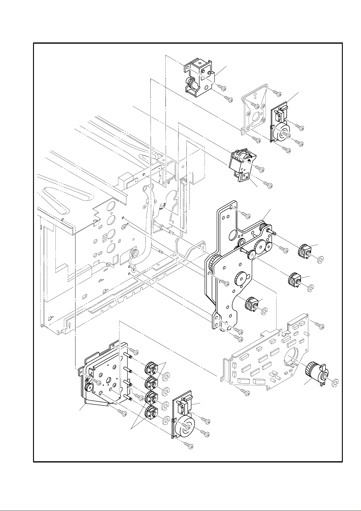
HL2400CPL
REF.NO.
1. DRIVE
CODE Q'TY DESCRIPTION REMARK
1 UH3500001 1 MAIN MOTOR
2 UH1941001 1 MAIN GEAR UNIT
3 UH1942001 1 DEVELOPER DRIVE MOTOR
4 UH1943001 1 DEVELOPER DRIVE UNIT
5 UH3494001 1 PAPER FEEDING CLUTCH
6 UH3495001 1 REGISTRATION CLUTCH
7 UH3496001 1 FUSER CLUTCH
8 UH3497001 5 DEVELOPER CLUTCH
9 UH3498001 1 TRANSFER SOLENOID
10 UH3499001 1 DRUM CLEANER SOLENOID
MODEL HL-2400C 54S-301
-1-
Page 5
1 . DRIVE
10
1
9
2
7
8
5
8
6
3
4
8
MODEL HL-2400C 54S-301
-2-
Page 6

HL2400CPL
2. FRAME
REF.NO. CODE Q'TYDESCRIPTION REMARK
1 UH1944001 2COOLING FAN MOTOR
2 UH1946001 3INTERLOCK SWITCH
3 UH1947001 1PAPER SIZE SENSOR
4 UH1948001 4PAPER SENSOR
5 UH1949001 2BELT SENSOR
6 UH1950001 1TONER SENSOR ASSY
7 UH1996001 1OHP SENSOR
8 UH3469001 1WASTE TONER FEEDER (U)
9 UH3483001 1DRUM CLEANER
10 UH3484001 1TRANSFER DRUM
11 UH3485001 1PAPER FEEDING ROLLER
12 UH3486001 1SEPARATOR PAD
13 UH3487001 1ERASE LAMP
14 UH3488001 1OIL SENSOR
15 UH3492001 1FUSER CONNECTOR
T/I NO. PR98003
MODEL HL-2400C 54S-301
-3-
Page 7

2 . FRAME
9
10
8
1
2
5
2
2
4
15
14
5
12
7
4
11
4
6
13
3
1
6
4
MODEL HL-2400C 54S-301
-4-
Page 8

3. SCANNER UNIT
REF.NO.
REF.NO.
CODE Q'TY DESCRIPTION REMARK
1 UH3482001 1 OPTICAL UNIT
HL2400CPL
MODEL HL-2400C 54S-301
4. MEDIA CASSETTE
CODE Q'TY DESCRIPTION REMARK
1 UH3493001 1 PAPER CASSETTE
MODEL HL-2400C 54S-301
-5-
Page 9

3 . SCANNER UNIT
1
MODEL HL-2400C 54S-301
4 . MEDIA CASSETTE
1
-6-
MODEL HL-2400C 54S-301
Page 10

HL2400CPL
5. TRANSFER UNIT
REF.NO. CODE Q'TYDESCRIPTION REMARK
1 UH3547001 1TRANSFER UNIT2
1-1 UH3480001 1TRANSFER ROLLER
1-2 UH3548001 1PAPER DISCHARGER2
MODEL HL-2400C 54S-301
T/I NO. PR98173
6. PAPER EXIT UNIT
REF.NO. CODE Q'TYDESCRIPTION REMARK
1 UH3459001 1PAPER EXIT UNIT
1-1 UH3460001 1PAPER EXIT UNIT COVER
1-2 UH3461001 1PAPER EXIT FRONT COVER
1-3 UH3462001 1PAPER EXIT ROLLER
1-4 UH3463001 1DISCHARGING BRUSH
1-5 UH1994001 1COOLING FAN MOTOR
1-6 UH1948001 2PAPER SENSOR
MODEL HL-2400C 54S-301
-7-
Page 11

1-2
5 . TRANSFER UNIT
1-1
1-4
1-2
6 . PAPER EXIT UNIT
1-6
1
MODEL HL-2400C 54S-301
1-1
1-4
1-3
1-6
1
MODEL HL-2400C 54S-301
-8-
Page 12

HL2400CPL
7. FUSING UNIT
REF.NO. CODE Q'TYDESCRIPTION REMARK
1 UH3470001 1FUSING UNIT (US)
1 UH3471001 1FUSING UNIT (EC)
1-1 UH3473001 1FUSING HEATER (US)
1-1 UH3474001 1FUSING HEATER (EC)
1-2 UH3476001 1FUSING ROLLER
1-3 UH3477001 1BACK-UP ROLLER
MODEL HL-2400C 54S-301
T/I NO. PR98252
8. MAIN PCB
REF.NO. CODE Q'TYDESCRIPTION SYMBOL REMARK
1 UK3900001 1MAIN PCB HLC1 B48K299-300Q
2 UK3902001 1MIO CONNECTOR PCB ASSY
3 UH1307001 1OPTIONAL I/O COVER H
4 UH1901001 1MAIN PCB PLATE
5 UH1903001 1MIO RAIL R
6 UH1940001 1MIO RAIL L
7 UH1904001 1CONNECTOR PCB HOLDER
8 UH1924001 2CARD BLIND
9 UK3942000 1MROM23C3210-2 VER.1.45
10 UK3941000 1MROM23C3210-1 VER.1.45
MODEL HL-2400C 54S-301
T/I NO. PR98034 / PR98038 / PR98045 / PR98058 / PR98117 / PR98212 / PR98229 / PR98266 /
PR99004
-9-
Page 13

7 . FUSING UNIT
1-1
1
MODEL HL-2400C 54S-301
8 . MAIN PCB
6
2
8
5
7
3
10
9
1
4
T/I NO. PR98038
MODEL HL-2400C 54S-301
-10-
Page 14

HL2400CPL
REF.NO.
9. COVER
CODE Q'TY DESCRIPTION REMARK
1 UH3451001 1 TOP COVER
2 UH3452001 1 SIDE COVER (R)
3 UH3453001 1 SIDE COVER (L)
4 UH3454001 1 UPPER SIDE COVER
5 UH3455001 1 PANEL BUTTON
6 UH3456001 1 PANEL PWB
7 UH3457001 1 FRONT COVER UNIT
7-1 UH3458001 1 FRONT COVER
8 UH3464001 1 BASE COVER (R)
9 UH3465001 1 BASE COVER (L)
10 UH3466001 1 REAR COVER
11 UH3467001 1 REAR COVER (U)
12 UH3468001 1 REAR COVER (L)
13 UH1945001 1 OZONE FILTER
MODEL HL-2400C 54S-301
-11-
Page 15

9 . COVER
5
4
6
11
1
3
10
12
9
13
7
2
7-1
MODEL HL-2400C 54S-301
-12-
8
Page 16

HL2400CPL
REF.NO.
REF.NO.
10. MCTL PCB PR98216
CODE Q'TY DESCRIPTION SYMBOL REMARK
1 UH1997001 1 MCTL PWB VER. LDA 1-4 CHNG VER.
MODEL HL-2400C 54S-301
T/I NO. PR98215 / PR98216
11. IOD PCB
CODE Q'TY DESCRIPTION REMARK
1 UH1998001 1 IOD1 PWB
2 UH1999001 1 IOD2 PWB
MODEL HL-2400C 54S-301
-13-
Page 17

10 . MCTL PWB
1
11 . IOD PCB
MODEL HL-2400C 54S-301
1
2
MODEL HL-2400C 54S-301
-14-
Page 18

HL2400CPL
REF.NO.
REF.NO.
12. POWER SUPPLY UNIT
CODE Q'TY DESCRIPTION SYMBOL REMARK
1 UH3490001 1 POWER SUPPLY UNIT (US) Rev:0B
1 UH3489001 1 POWER SUPPLY UNIT (EC) Rev:0B
MODEL HL-2400C 54S-301
13. HIGH VOLTAGE POWER SUPPLY
CODE Q'TY DESCRIPTION REMARK
1 UH2000001 1 HIGH VOLTAGE UNIT
MODEL HL-2400C 54S-301
-15-
Page 19

12 . POWER SUPLLY UNIT
1
13 . HIGH VOLTAGE POWER SUPPLY
1
MODEL HL-2400C 54S-301
-16-
MODEL HL-2400C 54S-301
Page 20

HL2400CPL
14. AC CORDS
REF.NO. CODE Q'TYDESCRIPTION REMARK
1A UH1933001 1AC CORD US/CSA
1B UH1052001 1AC CORD VDE
1C UH1053001 1AC CORD SEV
1D UH1054001 1AC CORD BS
1E UH1055001 1AC CORD SAA
1F U34320001 1AC CORD #4, BS WO/PLUG
1G UK4094001 1AC CORD #5, DEMKO
1H U34322001 1AC CORD #6, ISRAEL
MODEL HL-2400C 54S-301
T/I NO. PR98046
15. ACCESSORIES
REF.NO. CODE Q'TYDESCRIPTION REMARK
1 UK3850001 1P DRIVER DISK #1
2 UK3851001 1P DRIVER DISK #2
3 UK3852001 1P DRIVER DISK #3
4 UK3864001 1P DRIVER DISK PS
5 UK3870001 1P DRIVER DISK MAC
6 UK3866001 1P DRIVER DISK NT
7 UK3854001 1USER'S MANUAL ENG.
7 UK3855001 1USER'S MANUAL GER.
7 UK3856001 1USER'S MANUAL FRA.
7 UK3857001 1USER'S MANUAL DUT.
8 UE2014001 1PE BAG 215X350H
9 UK3676001 1P DRIVER DISK (E-MAIL PRINTING)
10 UK4125001 1P DRIVER DISK NT #2
11 UK3928001 1PANTONE DISK PCL
MODEL HL-2400C 54S-301
T/I NO. PR98002 / PR98195 / PR98275
-17-
Page 21

14 . AC CORDS
1A
1B
1C
1D
1E
1F
1G
1H
MODEL HL-2400C 54S-301
6
9
10
15 . ACCESSORIES
7
1
2
3
4
5
8
T/I NO. PR98002
MODEL HL-2400C 54S-301
-18-
Page 22

HL2400CPL
REF.NO.
REF.NO.
16. PACKING MATERIALS
CODE Q'TY DESCRIPTION REMARK
1 UH2151001 1 BASE/UPPER PACKING SET
2 UH2172001 1 POLYETHYLENE BAG (EN)
3 UH1932001 1 STARTER KIT PACKING SET
4 UH2164001 1 JOINT
5 UH1935001 1 HL-C1 CARTON
MODEL HL-2400C 54S-301
17. PERIODICAL REPLACEMENT PARTS
CODE Q'TY DESCRIPTION REMARK
1 UH3508001 1 40K KIT (US)
1 UH3509001 1 40K KIT (EC)
2 UH3510001 1 120K KIT
MODEL HL-2400C 54S-301
-19-
Page 23

16 . PACKING MATERIALS
1
4
2
3
1
5
1
4
MODEL HL-2400C 54S-301
17 . PERIODICAL REPLACEMENT PARTS
2
1
-20-
MODEL HL-2400C 54S-301
 Loading...