

Brother hl-2130, hl-2135w, hl-2220, hl-2230, hl-2240 Service Manual
...
Brother Laser Printer
SERVICE MANUAL
MODEL:
HL- 2130/2135W/2220/2230/2240/
2240D/2250DN/2270DW/2275DW
Read this manual thoroughly before maintenance work.
Keep this manual in a convenient place for quick and easy reference at all times.
September 2010
SM-PRN079
84UC0*
(8)
Confidential

The function comparative table for models as described in this Service Manual are shown below.
Model
HL-2130 HL-2135W HL-2220 HL-2230 HL-2240 HL-2240D HL-2250DN
LAN No Wireless No No No No Wired
HL-2270DW/
2275DW
Wired/
Wireless
Paper
edge
No No No No No No Yes Yes
sensor
Duplex
printing
No No No No No Yes Yes Yes
Manual
paper
tray
No No No Yes Yes Yes Yes Yes
cover
© Copyright Brother Industries, Ltd. 2010
Compilation and Publication:
This manual has been complied and published, under the supervision of Brother Industries Ltd.,
covering the latest product descriptions and specifications. The contents of this manual and the
specifications of this product are subject to change without notice. Brother reserves the right to make
changes without notice in the specifications and materials contained herein and shall not be
responsible for any damages (including consequential) caused by reliance on the materials presented,
including but not limited to typographical and other errors relating to the publication. This product is
designed for use in a professional environment.
Confidential

TABLE OF CONTENTS
REGULATION ...........................................................................................................vi
SAFETY INFORMATION ............................................................................................x
CHAPTER 1 SPECIFICATIONS ......................................................................... 1-1
1. SPECIFICATIONS LIST .............................................................................................................. 1-1
1.1 General ............................................................................................................................... 1-1
1.2 Network Connectivity .......................................................................................................... 1-4
1.3 Service Information ............................................................................................................. 1-5
1.4 Supplies .............................................................................................................................. 1-6
1.5 Paper .................................................................................................................................. 1-7
1.5.1 Paper handling ....................................................................................................... 1-7
1.5.2 Media specifications ............................................................................................... 1-7
1.6 Printable Area ..................................................................................................................... 1-8
CHAPTER 2 TROUBLESHOOTING ................................................................... 2-1
1. INTRODUCTION ......................................................................................................................... 2-1
1.1 Precautions ......................................................................................................................... 2-1
1.2 Initial Check ........................................................................................................................ 2-2
2. OVERVIEW ................................................................................................................................. 2-4
2.1 Cross-section Drawing ........................................................................................................ 2-4
2.2 Paper Feeding .................................................................................................................... 2-5
2.3 Operation of each part ........................................................................................................ 2-6
2.4 Block Diagram .................................................................................................................... 2-7
2.5 Components ....................................................................................................................... 2-8
3. LED ERROR INDICATION AND FAILURES .............................................................................. 2-9
3.1 LED indication at Operator Calls ........................................................................................ 2-9
3.2 LED indication at Service Calls ......................................................................................... 2-12
3.3 Error messages in the Status Monitor .............................................................................. 2-17
3.4 Error indication at Service Calls ........................................................................................ 2-18
3.5 Image Defect Examples .................................................................................................... 2-20
4. ERROR SYMPTOM/ERROR CAUSE AND REMEDY .............................................................. 2-21
4.1 Paper Feeding Problems .................................................................................................. 2-21
4.1.1 Pickup function of Paper tray does not work. ....................................................... 2-21
4.1.2 No feeding ............................................................................................................ 2-21
4.1.3 No paper fed manual feed slot ............................................................................. 2-22
4.1.4 Double feeding ..................................................................................................... 2-22
4.1.5 Paper jam ............................................................................................................. 2-23
i
Confidential

4.1.6 Dirt on paper ......................................................................................................... 2-25
4.1.7 Paper feeding at an angle .................................................................................... 2-25
4.1.8 Wrinkles or creases .............................................................................................. 2-26
4.1.9 Curl in the paper ................................................................................................... 2-27
4.1.10 Prints only single side of the paper when duplex-printing .................................... 2-28
4.1.11 Cannot make print through duplex-printing .......................................................... 2-28
4.1.12 Paper size error .................................................................................................... 2-28
4.1.13 Paper size error through duplex-printing .............................................................. 2-28
4.2 Troubleshooting Image Defect .......................................................................................... 2-29
4.2.1 Light ...................................................................................................................... 2-29
4.2.2 Faulty registration ................................................................................................. 2-31
4.2.3 Dark ...................................................................................................................... 2-31
4.2.4 Poor fixing ............................................................................................................ 2-32
4.2.5 Completely blank .................................................................................................. 2-32
4.2.6 Image distortion .................................................................................................... 2-33
4.2.7 All black ................................................................................................................ 2-33
4.2.8 The back of paper gets dirty ................................................................................. 2-33
4.2.9 Vertical streaks ..................................................................................................... 2-34
4.2.10 Black vertical streaks in a light background ......................................................... 2-34
4.2.11 Black horizontal stripes ........................................................................................ 2-35
4.2.12 White vertical streaks ........................................................................................... 2-36
4.2.13 White horizontal streaks ....................................................................................... 2-36
4.2.14 Faint print ............................................................................................................. 2-36
4.2.15 White spots ........................................................................................................... 2-37
4.2.16 Black spots ........................................................................................................... 2-37
4.2.17 Black band ............................................................................................................ 2-38
4.2.18 Downward fogging of solid black .......................................................................... 2-38
4.2.19 Horizontal lines ..................................................................................................... 2-38
4.2.20 Ghost .................................................................................................................... 2-39
4.2.21 Fogging ................................................................................................................ 2-39
4.3 Software Setting Problems ............................................................................................... 2-40
4.3.1 Cannot print data .................................................................................................. 2-40
4.4 Network Problems (Network model only) ......................................................................... 2-41
4.4.1 Cannot make a print through network connection ................................................ 2-41
4.5 Toner & Drum Problems ................................................................................................... 2-42
4.5.1 If replace toner, cannot delete "Replace Toner". .................................................. 2-42
4.5.2 Cannot detect toner .............................................................................................. 2-42
4.5.3 Toner low .............................................................................................................. 2-42
4.5.4 Replace toner ....................................................................................................... 2-42
4.5.5 The number of rotations of the developer roller reaches the upper limit .............. 2-43
4.5.6 No toner ................................................................................................................ 2-43
4.5.7 Drum life end soon ............................................................................................... 2-43
4.5.8 Drum error ............................................................................................................ 2-43
4.5.9 Drum stop ............................................................................................................. 2-43
4.6 Fuser Unit Problems ......................................................................................................... 2-44
4.6.1 Fuser Unit failure .................................................................................................. 2-44
ii
Confidential

4.7 Laser Unit Problems ......................................................................................................... 2-44
4.7.1 Laser Unit failure .................................................................................................. 2-44
4.8 PCB Problems .................................................................................................................. 2-45
4.8.1 Main PCB failure .................................................................................................. 2-45
4.8.2 Memory full ........................................................................................................... 2-45
4.8.3 Print overrun ......................................................................................................... 2-45
4.8.4 High voltage power supply PCB ASSY failure ..................................................... 2-45
4.8.5 Low voltage power supply PCB ASSY failure ...................................................... 2-46
4.9 Other Problems ................................................................................................................. 2-46
4.9.1 The printer is not turned on, or the LED indication does not appear. ................... 2-46
4.9.2 Fuser fan does not rotate. .................................................................................... 2-46
4.9.3 Main motor failure ................................................................................................. 2-47
4.9.4 Front cover open .................................................................................................. 2-47
4.9.5 Back cover open ................................................................................................... 2-47
CHAPTER 3 DISASSEMBLY AND ASSEMBLY ................................................ 3-1
1. SAFETY PRECAUTIONS ............................................................................................................ 3-1
2. PACKING .................................................................................................................................... 3-2
3. SCREW CATALOGUE ................................................................................................................ 3-3
4. SCREW TORQUE LIST .............................................................................................................. 3-4
5. LUBRICATION ............................................................................................................................ 3-5
6. OVERVIEW OF GEARS .............................................................................................................. 3-6
7. HARNESS ROUTING .................................................................................................................. 3-9
8. DISASSEMBLY FLOW ............................................................................................................. 3-17
9. DISASSEMBLY PROCEDURE ................................................................................................. 3-18
9.1 Paper Tray ........................................................................................................................ 3-19
9.2 Back Cover ....................................................................................................................... 3-22
9.3 Outer Chute ASSY ............................................................................................................ 3-24
9.4 Fuser Cover ...................................................................................................................... 3-25
9.5 Inner Chute ASSY, Eject Pinch Roller R ASSY and Eject Pinch Roller L ASSY .............. 3-26
9.6 Front Cover ASSY, Support Flap 1 ................................................................................... 3-28
9.7 Side Cover L ..................................................................................................................... 3-29
9.8 Side Cover R .................................................................................................................... 3-30
9.9 Top Cover ASSY .............................................................................................................. 3-31
9.10 Fuser Unit ......................................................................................................................... 3-35
9.11 Low voltage power supply PCB ASSY ............................................................................. 3-38
9.12 Fuser fan .......................................................................................................................... 3-41
9.13 High voltage power supply PCB ASSY ............................................................................. 3-42
9.14 Panel PCB ASSY .............................................................................................................. 3-43
9.15 Filter .................................................................................................................................. 3-44
iii
Confidential

9.16 Laser Unit ......................................................................................................................... 3-45
9.17 Wireless LAN PCB ASSY (Wireless network model only) ................................................ 3-47
9.18 Pick-up Roller Holder ASSY ............................................................................................. 3-48
9.19 Rubber Foot ...................................................................................................................... 3-49
9.20 Main PCB ASSY ............................................................................................................... 3-50
9.21 T1 Clutch ASSY, REG Clutch ASSY ................................................................................ 3-51
9.22 Main Frame L ASSY ......................................................................................................... 3-53
9.23 Develop Drive Sub ASSY, Develop Gear Joint/52 ........................................................... 3-55
9.24 Motor Drive Sub ASSY, Main Motor ................................................................................. 3-57
9.25 Paper Eject Sensor PCB ASSY ........................................................................................ 3-59
9.26 Fuser Gear 28/34 .............................................................................................................. 3-61
CHAPTER 4 ADJUSTMENTS AND UPDATING OF SETTINGS,
REQUIRED AFTER PARTS REPLACEMENT .............................. 4-1
1. IF YOU REPLACE THE MAIN PCB ASSY ................................................................................. 4-1
1.1 Rewriting the Firmware (Main Program) ............................................................................. 4-2
1.1.1 Checking firmware version ..................................................................................... 4-2
1.1.2 Rewriting the firmware ............................................................................................ 4-2
1.2 Setting the default paper size ............................................................................................. 4-3
1.3 Setting the serial number .................................................................................................... 4-4
1.4 Inputting the adjusted value of the laser unit ...................................................................... 4-6
2. IF YOU REPLACE THE LASER UNIT ...................................................................................... 4-10
2.1 Inputting the adjusted value of the laser unit .................................................................... 4-10
3. IF YOU REPLACE THE LOW VOLTAGE POWER SUPPLY PCB ASSY ............................... 4-14
3.1 Reset of Irregular Power Supply Detection Counter ......................................................... 4-14
CHAPTER 5 SERVICE FUNCTIONS .................................................................. 5-1
1. MAINTENANCE MODE ............................................................................................................... 5-2
1.1 How to Enter the End User-accessible Maintenance Mode ............................................... 5-2
1.2 How to Enter the Service Personnel-accessible Maintenance Mode ................................. 5-2
1.3 List of Maintenance Mode Functions .................................................................................. 5-3
1.4 Detailed Description of Maintenance-mode Functions ....................................................... 5-5
2. PRINTER SETTINGS ................................................................................................................ 5-13
2.1 Printout of Printer Settings ................................................................................................ 5-13
3. OTHER SERVICE FUNCTIONS ................................................................................................ 5-20
3.1 Reprint Function ............................................................................................................... 5-20
3.2 Job Cancel Function ......................................................................................................... 5-20
3.3 Wireless LAN setting (Wireless Network Model only) ....................................................... 5-21
3.4 Wireless Connecting Diagnostic Report Print (Wireless Network Model only) ................. 5-21
3.5 Continue Mode/Stop Mode settings of Toner Cartridge ................................................... 5-22
3.6 Drum Cleaning Function ................................................................................................... 5-22
iv
Confidential

CHAPTER 6 CIRCUIT DIAGRAMS, WIRING DIAGRAM ................................... 6-1
CHAPTER 7 PERIODICAL MAINTENANCE ...................................................... 7-1
1. PERIODICAL REPLACEMENT PARTS ..................................................................................... 7-1
APPENDIX 1 SERIAL NUMBERING SYSTEM .......................................... App. 1-1
APPENDIX 2 DELETION OF USER SETTING INFORMATION ................ App. 2-1
APPENDIX 3 INSTALLING THE MAINTENANCE PRINTER DRIVER ...... App. 3-1
APPENDIX 4
HOW TO MAKE PROTECTIVE MATERIAL OF DRUM UNIT
..... App. 4-1
v
Confidential

REGULATION
<For Europe and Other countries>
Radio interference (220 to 240 volt model only)
This printer follows EN55022 (CISPR Publication 22)/Class B.
IEC 60825-1: 2007 specification (220 to 240 volt model only)
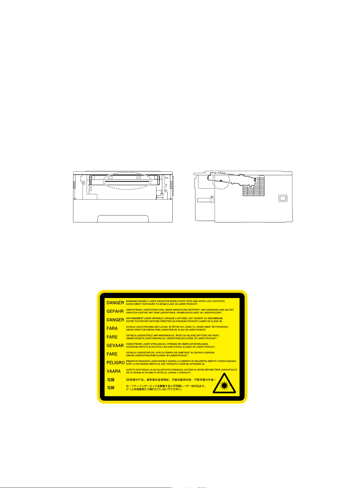
This printer is a Class 1 laser product as defined in IEC 60825-1: 2007 specifications.
The label shown below is attached in countries where it is needed.
CLASS 1 LASER PRODUCT
APPAREIL À LASER DE CLASSE 1
LASER KLASSE 1 PRODUKT
This printer has a Class 3B laser diode which produces invisible laser radiation in the laser
unit. You should not open the laser unit under any circumstances.
Caution
Use of controls or adjustments or performance of procedures other than those specified in
this manual may result in hazardous radiation exposure.
For Finland and Sweden
LUOKAN 1 LASERLAITE
KLASS 1 LASER APPARAT
Varoitus!
Laitteen käyttäminen muulla kuin tässä käyttöohjeessa mainitulla tavalla saattaa altistaa
käyttäjän turvallisuusluokan 1 ylittävälle näkymättömälle lasersäteilylle.
Varning
Om apparaten används på annat sätt än i denna Bruksanvisning specificerats, kan
användaren utsättas för osynlig laserstrålning, som överskrider gränsen för laserklass 1.
vi
Confidential

Internal laser radiation
Maximum radiation power: 25 mW
Wave length: 770 - 800 nm
Laser class: Class 3B
EU Directive 2002/96/EC and EN50419
(European Union only)
This equipment is marked with the recycling symbol below. It means that at the end of the
life of the equipment you must dispose of it separately at an appropriate collection point and
not place it in the normal domestic unsorted waste stream. This will benefit the environment
for all. (European Union only)
vii
Confidential

<For USA and Canada>
Federal Communications Commission (FCC) Declaration of Conformity
(For USA)
Responsible Party: Brother International Corporation
100 Somerset Corporate Boulevard
P. O . B o x 6 9 11
Bridgewater, NJ 08807-0911
USA
Telephone: (908) 704-1700
declares, that the products
Product name: Laser Printer HL-2130, HL-2135W, HL-2220, HL-2230, HL-2240,
HL-2240D, HL-2250DN, HL-2270DW and HL-2275DW
Model number: HL-22
complies with Part 15 of the FCC Rules. Operation is subject to the following two conditions:
(1) This device may not cause harmful interference, and (2) this device must accept any
interference received, including interference that may cause undesired operation.
This equipment has been tested and found to comply with the limits for a Class B digital
device, pursuant to Part 15 of the FCC Rules. These limits are designed to provide
reasonable protection against harmful interference in a residential installation. This
equipment generates, uses, and can radiate radio frequency energy and, if not installed and
used in accordance with the instructions, may cause harmful interference to radio
communications. However, there is no guarantee that interference will not occur in a
particular installation. If this equipment does cause harmful interference to radio or television
reception, which can be determined by turning the equipment off and on, the end user is
encouraged to try to correct the interference by one or more of the following measures:
• Reorient or relocate the receiving antenna.
• Increase the separation between the equipment and receiver.
• Connect the equipment into an outlet on a circuit different from that to which the receiver is
connected.
• Consult the dealer or an experienced radio/TV technician for help.
Important
A shielded interface cable should be used to ensure compliance with the limits for a Class B
digital device. Changes or modifications not expressly approved by Brother Industries, Ltd.
could void the user’s authority to operate the equipment.
viii
Confidential

Industry Canada Compliance Statement (For Canada)
This Class B digital apparatus complies with Canadian ICES-003.
Cet appareil numérique de la classe B est conforme à la norme NMB-003 du Canada.
Laser Safety (110 to 120 volt model only)
This printer is certified as a Class 1 laser product under the U.S. Department of Health and
Human Services (DHHS) Radiation Performance Standard according to the Radiation
Control for Health and Safety Act of 1968. This means that the printer does not produce
hazardous laser radiation.
Since radiation emitted inside the printer is completely confined within protective housings
and external covers, the laser beam cannot escape from the printer during any phase of user
operation.
FDA Regulations (110 to 120 volt model only)
The U.S. Food and Drug Administration (FDA) has implemented regulations for laser
products manufactured on and after August 2, 1976. Compliance is mandatory for products
marketed in the United States. The following label on the back of the printer indicates
compliance with the FDA regulations and must be attached to laser products marketed in the
United States.
MANUFACTURED:
Brother Technology (Shenzhen) Ltd.
NO6 Gold Garden Ind., Nanling Nanwan, Longgang, Shenzhen, China
This product complies with FDA performance standards for laser products except for
deviations pursuant to Laser Notice No.50, dated Jun 24, 2007.
Internal laser radiation
Maximum radiation power: 25 mW
Wave length: 770 - 800 nm
Laser class: Class 3B
ix
Confidential
SAFETY INFORMATION
Caution for Laser Product (WARNHINWEIS fur Laser drucker)
CAUTION: When the printer during servicing is operated with the cover open, the
regulations of VBG 93 and the performance instructions for VBG 93 are
valid.
CAUTION: In case of any trouble with the laser unit, replace the laser unit itself. To
prevent direct exposure to the laser beam, do not try to open the enclosure
of the laser unit.
ACHTUNG: Im Falle von Störungen der Lasereinheit muß diese ersetzt werden. Das
Gehäuse der Lasereinheit darf nicht geöffnet werden, da sonst
Laserstrahlen austreten können.
<Location of the laser beam window>
Additional Information
When servicing the optical system of the printer, be careful not to place a screwdriver or
other reflective object in the path of the laser beam. Be sure to take off any personal
accessories such as watches and rings before working on the printer. A reflected beam,
though invisible, can permanently damage the eyes.
Since the beam is invisible, the following caution label is attached on the laser unit.
x
Confidential

Definitions of Warnings, Cautions, Notes and Memos
The following conventions are used in this manual:
Mark Contents
Warnings tell you what to do to prevent possible personal injury.
Electrical Hazard icons alert you to a possible electrical shock.
Hot Surface icons warn you not to touch printer parts that are hot.
Cautions specify procedures you must follow or avoid to prevent
possible damage to the printer or other objects.
Note Notes tell you useful tips when servicing the printer.
Memo Memo tells you bits of knowledge to help understand the printer.
xi
Confidential
Safety Precautions
Listed below are the various kinds of “WARNING” messages included in this manual.
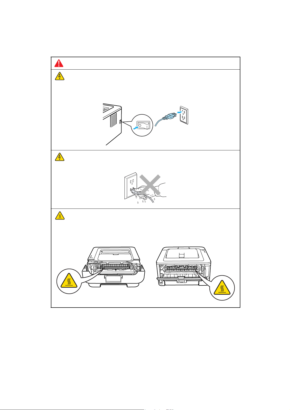
WARNING
There are high voltage electrodes inside the printer. Before you clean the inside of
the printer or replace parts, make sure that you have turned off the power switch and
unplugged the printer from the AC power outlet.
DO NOT handle the plug with wet hands. Doing this might cause an electrical shock.
The fuser unit becomes extremely hot during operation. Wait until it has cooled down
sufficiently before replacing consumable items. DO NOT remove or damage the
caution label located on or around the fuser.
xii
Confidential
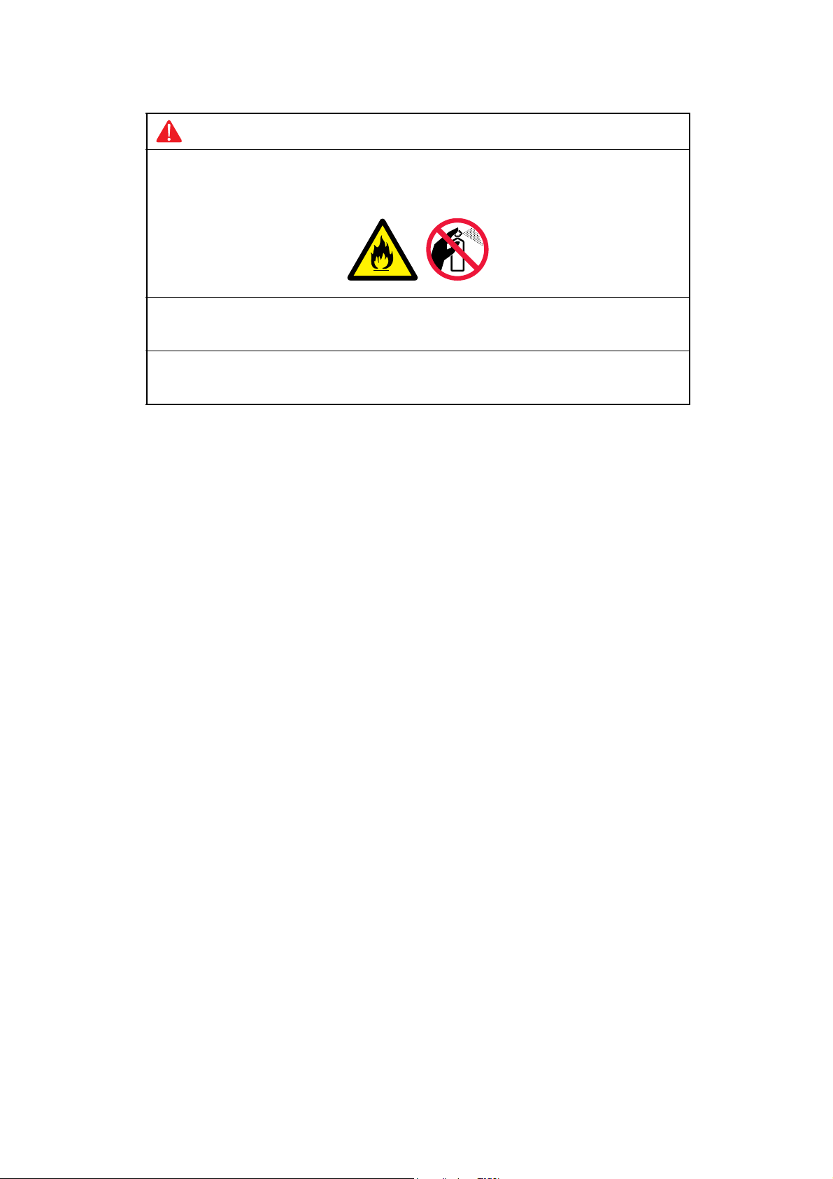
WARNING
DO NOT use flammable substances such as alcohol, benzine, thinner or any type of
spray to clean the inside or outside of the printer. Doing this may cause a fire or
electrical shock.
If the printer becomes hot, blows smoke, or generates obscure odor, immediately turn
off the power switch and unplug the printer from the AC power outlet.
If metal objects, water or other liquids get inside the printer, immediately turn off the
power switch and unplug the printer from the AC power outlet.
Caution
Lightning and power surges can damage this product! We recommend that you use a quality
surge protection device on the AC power line, or unplug the printer during a lightning storm.
xiii
Confidential
CHAPTER 1 SPECIFICATIONS
1. SPECIFICATIONS LIST
1.1 General
Model HL-2130 HL-2135W HL-2220 HL-2230
Print method Electrophotographic / Laser
Resolution
Print speed Up to 20/21 ppm (A4/Letter size)
Warm-up time
First print time
CPU
Memory
Interface
Power
Consumption
Noise level
Environment Temperature
Dimensions
(WxDxH)
Weights
From Sleep mode Less than 7 seconds at 23°C (73.4 F)
From Power
→ ON
OFF:
From Ready mode Less than 10 seconds Less than 8.5
From Sleep mode Less than 19 seconds Less than
Peak
Printing
Ready
Sleep,
Wireless LAN: ON
Deep Sleep
Sound
pressure
Sound
power
Humidity
Carton
Printer
without Carton,
with toner/drum
Printing
Ready
Printing For U.S.A./China LWAd = 6.60 B(A)
Ready For U.S.A./China LWAd = 4.60 B(A)
600 x 600 dpi, HQ1200 (2400 x 600 dpi) quality
Up to 24/24 ppm
(A4/Letter size)
* When loading A4 or Letter-size paper from the paper tray.
Less than 25
seconds at
23°C (73.4 F)
ARM9 200MHz
8 MB 16 MB 8 MB
Hi-Speed
USB 2.0
1056W
Average: Approx. 421 W
Average: Approx. 62 W
N/A Average:
Average:
Approx. 0.8 W
LWAd = 53 dB(A)
LWAd = 31 dB(A)
Except for U.S.A./China LWAd = 6.40 B(A)
Except for U.S.A./China LWAd = 4.54 B(A)
Operating: 10 to 32.5°C
Storage: 0 to 40°C
Operating: 20 to 80 %
Storage: 10 to 90 %
475 x 454 x 331 mm (18.7 x 17.9 x 13.0 in.)
368 x 360 x 183 mm (14.5 x 14.2 x 7.2 in.)
6.7kg / 14.8lb
Less than 26
seconds at
23°C (73.4 F)
Hi-Speed USB 2.0,
IEEE802.11b/g
(Infrastructure
Mode/Adhoc Mode)
Approx. 2.8 W
Average:
Approx. 0.9 W
Less than 25 seconds at
23°C (73.4 F)
seconds
16.5 seconds
Hi-Speed USB 2.0
Average:
Approx. 495 W
Average:
Approx. 65 W
N/A
Average:
Approx. 0.8 W
Average:
Approx. 0.9 W
LWAd = 6.70
B(A)
LWAd = 4.60
B(A)
Specifications are subject to change without prior notice.
1-1
Confidential
Model HL-2240 HL-2240D HL-2250DN
Print method Electrophotographic / Laser
Resolution
Print speed
600 x 600 dpi, HQ1200 (2400 x 600 dpi) quality
Up to 24/24 ppm
(A4/Letter size)
* When loading A4 or Letter-size paper from the paper tray.
Warm-up time
First print time
From Sleep mode Less than 7 seconds at 23°C (73.4 F)
From Power
→ ON
OFF:
Less than 25 seconds at
23°C
(73.4 F)
From Ready mode Less than 8.5 seconds
From Sleep mode Less than 16.5 seconds
CPU
Memory
Interface
Power
Consumption
Peak
Printing
Ready
Sleep,
ARM9 200MHz
8 MB 32 MB
Hi-Speed USB 2.0
1056W
Average: Approx. 495 W
Average: Approx. 65 W
N/A Average:
Wireless LAN: ON
Noise level
Deep Sleep
Sound
pressure
Sound
Printing
Ready
Printing LWAd = 6.70
power
Average: Approx. 0.9 W
LWAd = 53 dB(A)
LWAd = 31 dB(A)
For U.S.A./
B(A)
China LWAd
= 6.70 B(A)
Except for
U.S.A./China
LWAd =
6.65 B(A)
Ready LWAd = 4.60
B(A)
For U.S.A./
China LWAd
= 4.60 B(A)
Except for
U.S.A./China
LWAd =
4.50 B(A)
Environment Temperature
Operating: 10 to 32.5°C
Storage: 0 to 40°C
Humidity
Operating: 20 to 80 %
Storage: 10 to 90 %
Dimensions
(WxDxH)
Weights
Carton
Printer
without Carton,
475 x 454 x 331 mm (18.7 x 17.9 x 13.0 in.)
368 x 360 x 183 mm (14.5 x 14.2 x 7.2 in.)
6.7kg / 14.8lb 7.0kg / 15.4lb
with toner/drum
Specifications are subject to change without prior notice.
HL-2270DW/
2275DW
Up to 26/27 ppm
(A4/Letter size)
Less than 26 seconds at
23°C (73.4 F)
Hi-Speed USB
2.0, Ethernet
10/100 BASETX
Hi-Speed USB
2.0, Ethernet
10/100 BASETX,
IEEE802.11b/g
(Infrastructure
Mode/Adhoc
Mode)
Approx. 2.8 W
For U.S.A./China LWAd =
6.70 B(A)
Except for U.S.A./
China LWAd = 6.67 B(A)
For U.S.A./China LWAd =
4.60 B(A)
Except for U.S.A./
China LWAd = 5.02 B(A)
1-2
Confidential

<Computer requirements>
Computer Platform &
Operating System
Version
Windows®
Operating
System
Windows®
2000
Professional
*1
Processor Minimum
Speed
Intel® Pentium® II or
equivalent
Windows®
XP Home
Edition
®
Windows
XP
Professional
Windows
®
XP
Professional
64-bit (Intel
AMD 64) supported
CPU
®
64 or
x64 Edition
Windows
®
Vista
Intel® Pentium® 4 or
equivalent 64-bit
®
(Intel
64 or AMD 64)
supported CPU
Windows
®
7 Intel® Pentium® 4 or
equivalent 64-bit
®
(Intel
64 or AMD 64)
supported CPU
Windows
®
Server
®
Pentium® III or
Intel
equivalent
2003
Windows
®
Server
2003 x64
64-bit (Intel
AMD 64) supported
CPU
®
64 or
Edition
Windows
®
Server
2008
®
Pentium® 4 or
Intel
equivalent 64-bit
®
(Intel
64 or AMD 64)
supported CPU
®
64 or
®
G4/G5
Core™
Core™
Macintosh
Operating
System
*1 Microsoft
Windows
®
Server
2008 R2
Mac OS X
10.4.11
and 10.5.x
Mac OS X
10.6.x
®
Internet Explorer® 6.0 or greater.
64-bit (Intel
AMD 64) supported
CPU
Power PC
®
Intel
Processor
®
Intel
Processor
*2 Third party USB ports are not supported.
Hard
Disk
Space
to install
Minimum
RAM
Recommended
RAM
64 MB 256 MB 50 MB
128 MB
256 MB 512 MB
512 MB 1 GB
1 GB
(32-bit)
2 GB
(64-bit)
1 GB
(32-bit)
2 GB
(64-bit)
256 MB 512 MB
512 MB 2 GB
512 MB 1 GB 80 MB
1 GB 2 GB
Supported PC
Interface
*2
USB,
10BASE-T /
100BASE-TX
(Ethernet),
Wireless
802.11b/g
Specifications are subject to change without prior notice.
1-3
Confidential

1.2 Network Connectivity
Model HL-2130 HL-2135W HL-2220 HL-2230
Wired network Network node
type
Network type
Wireless network Network node
type
Network type
Network security
N/A
N/A
N/A NC-7800w N/A
N/A
N/A
IEEE
802.11b/g
(Infrastructure
Mode / Adhoc
Mode)
WEP 64/128
bit, WPA-PSK
(TKIP/AES),
WPA2-PSK
(AES), APOP,
POP before
SMTP,
SMTP-AUTH
N/A
N/A
Model HL-2240 HL-2240D HL-2250DN
Wired network Network node
type
Network type
Wireless network Network node
type
Network type
Network security N/A
Specifications are subject to change without prior notice.
N/A NC-8200h
N/A 10/100BASE-TX
N/A NC-7800w
N/A
HL-2270DW/
2275DW
IEEE
802.11b/g
(Infrastructure
Mode / Adhoc
Mode)
WEP 64/128
bit, WPA-PSK
(TKIP/AES),
WPA2-PSK
(AES), APOP,
POP before
SMTP,
SMTP-AUTH
1-4
Confidential

1.3 Service Information
Model HL-2130 HL-2135W HL-2220 HL-2230
Printer life 50,000 pages (A4 / Letter) or 5 years under normal use
MTBF 4,000 hours
MTTR 0.5 hours
Maximum monthly volume Up to 8,000 pages Up to 10,000
Parts life Fuser Unit 50,000 pages or 5 years
Laser Unit
PF kit
at normal temperature and humidity.
pages
Model HL-2240 HL-2240D HL-2250DN
Printer life 50,000 pages (A4 / Letter) or 5 years under normal use
at normal temperature and humidity.
MTBF 4,000 hours
MTTR 0.5 hours
Maximum monthly volume Up to 10,000 pages
Parts life Fuser Unit 50,000 pages or 5 years
Laser Unit
PF kit
Specifications are subject to change without prior notice.
HL-2270DW/
2275DW
1-5
Confidential
1.4 Supplies
Toner cartridge Starter Toner Approx. 700 pages
Approx. cartridge yield is declared in accordance with ISO/IEC 19752
Shelf life: 2 years without opening (6 months after opening)
Drum unit
Model HL-2130 HL-2135W HL-2220 HL-2230
Standard Toner
High Capacity
Ton er
Except for
Asia Approx.
1,000 pages
For Asia: 700
pages
N/A Approx. 2,600 pages
Life expectancy: Approx. 12,000 pages/drum unit
The life expectancy varies according to the use condition.
Shelf life: 2 years
Approx.
1,000 pages
Approx. 1,200 pages
Model HL-2240 HL-2240D HL-2250DN
Toner cartridge Starter Toner Approx. 700
pages
Standard Toner Approx. 1,200 pages
High Capacity
Ton er
Approx. cartridge yield is declared in accordance with ISO/IEC 19752
Shelf life: 2 years without opening (6 months after opening)
Drum unit
The shelf life of toner cartridge and drum unit is guaranteed under the normal condition as below;
(Temperature) Normal condition: 0 to 40 °C
* Storage condition at the temperature of 40 to 50 °C: Up to 5 days
* Storage condition at the temperature of -20 to 0 °C: Up to 5 days
(Humidity) Normal condition: 35 to 85 %
* Storage condition at the humidity of 85 to 95 %: Up to 5 days
* Storage condition at the humidity of 10 to 35%: Up to 5 days
Specifications are subject to change without prior notice.
Approx. 2,600 pages
Life expectancy: Approx. 12,000 pages/drum unit
The life expectancy varies according to the use condition.
Shelf life: 2 years
Except for Asia/Russia
Approx. 700 pages
For Asia/Russia: Approx.
1,200 pages
HL-2270DW/
2275DW
For U.S.A./
Oceania:
Approx. 700
pages
For Europe/
Asia:
Approx. 1,200
pages
<HL-2275DW>
Approx. 1,200
pages
1-6
Confidential
1.5 Paper
1.5.1 Paper handling
Model HL-2130 HL-2135W HL-2220 HL-2230
Paper Input Manual feed slot 1 sheet
Paper Output Face-down 100 Sheets (80g/m2)
Paper tray
Face-up 1 sheet (straight paper path)
250 sheets
Model HL-2240 HL-2240D HL-2250DN
Paper Input Manual feed slot 1 sheet
Paper tray
Paper Output Face-down 100 Sheets (80g/m2)
Face-up 1 sheet (straight paper path)
1.5.2 Media specifications
Model HL-2130 HL-2135W HL-2220 HL-2230
Media type Paper tray Plain Paper, Thin Paper, Recycled Paper
Manual Feed Slot
Duplex printing N/A
Media weight Paper tray
Manual Feed Slot
Duplex printing N/A
Media size Paper tray
Manual Feed Slot
Duplex printing N/A
HL-2270DW/
2275DW
250 sheets
Plain Paper, Thin Paper, Thick Paper, Recycled Paper,
Bond Paper, Labels, Envelopes
60 - 105 g/m2 (16 - 28 lb)
60 - 163 g/m2 (16 - 43 lb)
A4, Letter, B5 (ISO/JIS), A5, A5 (Long Edge), B6 (ISO), A6,
Executive, Legal, Folio 16K (only for U.S.A./China)
Width 76.2 to 216 mm, Length 116 to 406.4 mm
(Width 3.0 to 8.5 in., Length 4.6 to 16 in.)
Model HL-2240 HL-2240D HL-2250DN
Media type Paper tray Plain Paper, Thin Paper, Recycled Paper
Manual Feed Slot
Duplex printing N/A
Media weight Paper tray
Manual Feed Slot
Duplex printing N/A
Media size Paper tray
Manual Feed Slot
Duplex printing N/A
Specifications are subject to change without prior notice.
Plain Paper, Thin Paper, Thick Paper, Recycled Paper,
Bond Paper, Labels, Envelopes
Plain Paper, Thin Paper, Recycled Paper
60 - 105 g/m2 (16 - 28 lb)
60 - 163 g/m2 (16 - 43 lb)
60 - 105 g/m2 (16 - 28 lb)
A4, Letter, B5 (ISO/JIS), A5, A5 (Long Edge), B6 (ISO), A6,
Executive, Legal, Folio, 16K (only for China)
Width 76.2 to 216 mm, Length 116 to 406.4 mm
(Width 3.0 to 8.5 in., Length 4.6 to 16 in.)
For U.S.A. : Letter, Legal, Folio
Except for U.S.A. : A4
1-7
HL-2270DW/
2275DW
Confidential
1.6 Printable Area
The area of the paper that cannot be printed on is shown in the table below:
Portrait
1
24
3
A4 Letter Legal B5 (ISO)
4.23 mm
1
(0.16 in.)
6.01 mm
2
(0.24 in.)
4.23 mm
3
(0.16 in.)
6.01 mm
4
(0.24 in.)
Landscape
A4 Letter Legal B5 (ISO)
4.23 mm
1
(0.16 in.)
5.0 mm
2
(0.19 in.)
4.23 mm
3
(0.16 in.)
5.0 mm
4
(0.19 in.)
4.23 mm
(0.16 in.)
6.35 mm
(0.25 in.)
4.23 mm
(0.16 in.)
6.35 mm
(0.25 in.)
4.23 mm
(0.16 in.)
5.08 mm
(0.2 in.)
4.23 mm
(0.16 in.)
5.08 mm
(0.2 in.)
Executive
4.23 mm
(0.16 in.)
6.35 mm
(0.25 in.)
4.23 mm
(0.16 in.)
6.35 mm
(0.25 in.)
24
4.23 mm
(0.16 in.)
6.01 mm
(0.24 in.)
4.23 mm
(0.16 in.)
6.01 mm
(0.24 in.)
1
3
4.23 mm
(0.16 in.)
6.35 mm
(0.25 in.)
4.23 mm
(0.16 in.)
6.35 mm
(0.25 in.)
Executive
4.23 mm
(0.16 in.)
5.08 mm
(0.2 in.)
4.23 mm
(0.16 in.)
5.08 mm
(0.2 in.)
4.23 mm
(0.16 in.)
5.0 mm
(0.19 in.)
4.23 mm
(0.16 in.)
5.0 mm
(0.19 in.)
4.23 mm
(0.16 in.)
5.08 mm
(0.2 in.)
4.23 mm
(0.16 in.)
5.08 mm
(0.2 in.)
A5 A6 B6 (ISO)
4.23 mm
(0.16 in.)
6.01 mm
(0.24 in.)
4.23 mm
(0.16 in.)
6.01 mm
(0.24 in.)
4.23 mm
(0.16 in.)
6.01 mm
(0.24 in.)
4.23 mm
(0.16 in.)
6.01 mm
(0.24 in.)
A5 A6 B6 (ISO)
4.23 mm
(0.16 in.)
5.0 mm
(0.19 in.)
4.23 mm
(0.16 in.)
5.0 mm
(0.19 in.)
4.23 mm
(0.16 in.)
5.0 mm
(0.19 in.)
4.23 mm
(0.16 in.)
5.0 mm
(0.19 in.)
4.23 mm
(0.16 in.)
6.01 mm
(0.24 in.)
4.23 mm
(0.16 in.)
6.01 mm
(0.24 in.)
4.23 mm
(0.16 in.)
5.0 mm
(0.19 in.)
4.23 mm
(0.16 in.)
5.0 mm
(0.19 in.)
Specifications are subject to change without prior notice.
1-8
Confidential
CHAPTER 2 TROUBLESHOOTING
1. INTRODUCTION
Troubleshooting is the countermeasure procedures that the service personnel should follow
if an error or malfunction occurs with the printer. It is impossible to anticipate all of the
possible troubles which may occur in future and determine the troubleshooting procedures,
so this chapter covers some sample troubles. However, those samples will help the service
personnel pinpoint and repair other defective elements.
1.1 Precautions
Be sure to observe and follow all the precautions to prevent any secondary problems from
happening during troubleshooting.
(1) Always turn off the power and unplug the power cable before removing any covers or
PCBs, adjusting the printer and so on. If you need to take voltage measurements with
the power switched on, take the greatest of care not to receive an electric shock.
(2) When connecting or disconnecting cable connectors, make sure that you hold the
connector body and not the cables.
(3) Static electricity charged in your body may damage electronic parts.
Before handling the PCBs, touch a metal portion of the printer to discharge static
electricity charged in your body. When transporting PCBs, be sure to wrap them in
conductive sheets.
When replacing the PCBs, put on a grounding wrist band and perform the job on a
conductive mat. Also take care not to touch the conductor sections on the flat cables.
(4) Follow the warning by all means.
The fuser unit becomes extremely hot during operation. Wait until it has cooled down
sufficiently before replacing consumable items. DO NOT remove or damage the
caution label located on or around the fuser.
WARNING
DO NOT use flammable substances such as alcohol, benzine, thinner or any type of
spray to clean the inside or outside of the printer. Doing this may cause a fire or
electrical shock.
(5) Verify again that the repaired portion works properly.
2-1
Confidential

1.2 Initial Check
Check the following items before attempting to repair the printer.
■ Operating Environment
(1) Put your printer on a flat, stable surface such as a desk that is free of vibration and
shocks.
(2) Use the printer in a well-ventilated room; use the printer within the following ranges of
temperature and humidity: temperature between 10°C and 32.5°C (50°F to 90.5°F), and
the relative humidity is maintained between 20% and 80%.
(3) The printer is not exposed to direct sunlight, excessive heat, moisture, or dust.
(4) Keep the printer horizontal when you carry it.
■ Power Supply
(1) The AC input power supply described on the rating plate of the printer should be within
±10% of the rated voltage.
(2) The AC input power supply is within the regulated value.
(3) The cables and harnesses are connected correctly.
(4) The fuses are not blown.
■ Paper
(1) A recommended type of paper is being used.
(Refer to "1.5.2 Media specifications" in Chapter 1.)
(2) The paper is not damp.
(3) The paper is not short-grained paper or acid paper.
■ Consumable Parts
(1) The drum unit (including the toner cartridge) is installed correctly.
2-2
Confidential
■ Others
(1) Condensation
When the printer is moved from a cold place into a warm room, condensation may occur
inside the printer, causing various problems as listed below.
• Condensation on the optical surfaces such as the lenses, the reflection mirror and the
protection glass may cause the print image to be light.
• If the exposure drum is cold, the electrical resistance of the photosensitive layer is
increased, making it impossible to obtain the correct contrast when printing.
• Condensation on the charge unit may cause corona charge leakage.
• Condensation on the plate and separation pad may cause paper feed failures.
If condensation has occurred, leave the printer for at least two hours to allow it to reach
room temperature.
If the drum unit is unpacked soon after it is moved from a cold place to a warm room,
condensation may occur inside the unit which may cause incorrect images. Instruct the
user to allow the unit to come to room temperature before unpacking it. This will take one
or two hours.
(2) Low temperature
The motor may not drive normally under the low temperature environment. This is due to
there being too much load to drive each unit. In this case, increase the room
temperature.
■ Cleaning
Use a soft dry lint-free cloth.
CAUTION:
DO NOT use flammable substances, any type of spray or any organic solvent/liquids
contains alcohol or ammonia to clean the inside or outside of the printer. Doing this may
cause a fire or electrical shock.
2-3
Confidential

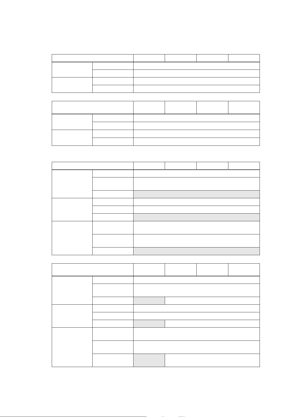
2. OVERVIEW
2.1 Cross-section Drawing
Back cover
Eject roller 1
Paper eject
actuator
Heat roller
Eject roller 2 Eject Pinch Roller Exposure drum Develop roller Supply roller Laser unit
<Front side><Back side>
Registration
rear actuator
Manual paper
tray cover
Registration
front actuator
Regist roller
Paper edge
actuator
Paper tray
Fig. 2-1
2-4
DX feed rollerDX feed roller Duplex Tray Transfer roller PlateHalogen heaterPressure roller
Pick-up
roller
Separation
roller
Separation
pad
Confidential
2.2 Paper Feeding
Rear paper eject path
Duplex path
Manual feed slot path
Paper tray path
Fig. 2-2
2-5
Confidential

2.3 Operation of each part
Part name Operation
Pick-up roller Feed the paper from the paper tray.
Separation roller and
Separation pad
Paper edge actuator
(HL-2250DN/2270DW/2275DW
only)
Registration front actuator Detect the front edge of paper, and control the drive of
Registration roller When the front edge of the paper hit the stopped registration
Registration rear actuator Detect the passage of paper and adjust the starting position
Transfer roller By applying a minus charge to the transfer roller, the toner
Heat roller and Pressure roller The toner transferred on paper being fused by heat and
Paper eject actuator Detect whether or not paper is ejected from the fuser unit.
Eject roller 1 Feed the paper ejected from the fuser unit to the eject roller 2.
Separate into single sheet from the paper tray.
Detect the rear edge of paper, and identify the paper size.
registration roller.
When feeding from the manual feed slot, detect the passage
of paper.
Detect the paper jam of front part.
roller and the inclination of the paper is corrected.
for writing on a sheet of paper.
When the duplex printing, detect the rear edge of paper and
adjust the timing of eject roller 2 switching.
adhered to the exposure drum is transferred to paper, and
feed the paper to the fuser unit.
pressure, and feed the paper to the eject roller 1.
Eject roller 2 Eject the paper to the face-down output tray.
When the duplex printing, after the paper is fed from the eject
roller 2 with the front of sheet printed, the eject roller 2 rotates
conversely and feed the paper to the duplex tray.
DX feed roller
(HL-2240D/2250DN/2270DW/
2275DW only)
Feed the paper passed in the duplex tray to the registration
roller.
2-6
Confidential

2.4 Block Diagram
Registration front/rear sensor PCB
Registration front sensor
Registration rear sensor
Low voltage power supply PCB
Heater Switch
Wireless LAN
PCB ASSY
Panel PCB ASSY
Error LED
Drum LED
Toner LED
Paper Edge Sensor PCB
(HL-2250DN/2270DW/
2275DW only)
Paper Edge Sensor
Fuser Unit
Center thermistor
Side thermistor
Fuser FAN
Paper eject sensor PCB
Paper eject sensor
Back cover/DX
High voltage power supply PCB
Front cover sensor
Main PCB ASSY
Fig. 2-3
Ready LED
Go Key
T1 clutch ASSY
REG clutch ASSY
Main motor
LD control PCB ASSY
BD sensor
New toner sensor
Laser unit
Polygon motor
2-7
Confidential
 Loading...