

Page 1
SERVfCE
MANUAL
BROTHER
-1
00·-200·-400·-500
(
FOR
MODEL
DB2-B705
\
r
----
BROTHER
INDUSTRIES,
NAGOYA,
JAPAN
.
LTD.,
Page 2

PREFACE
Thi
s service manual is
tr
imm
er seri
es,
Norma
l troubl
es occur
made
BROTHER
in your
for the
Model 082-8705-100 Series .
sew
purpo
se
of getting
ing room will be solved wi
acquai
nted with our newly designed
th
the knowledge
of instruction manual
thread
encl osed
this
knowled
Incide
however, if you u
We sincerely hop e th
pamphlet.
with th
se
rvi
ce
ge on this machine by this servi
ntall
e machine, however,
manual ma
y,
this
covers
se
y be helpful for you r
the description on
with ot
at
you wi
her bran's, pi
ll
overco
in order
ce
manual
our
ease
me the
to
get
much m
bette
r ma intenance. We duly h
as well
newly developed
refer to one
tro
ubles which
ore perfect
as instruction
BROTHER
published by
may ari
BROTHER INDUSTR
knowledge
manuals
Needle Positioning Motor,
tho
se
manufa
se
in
ope
and
your
on
this machine,
that
you
parts catalog
cture
r.
factory wi
IES,
get full
ues.
th
this
LTD
.
Page 3
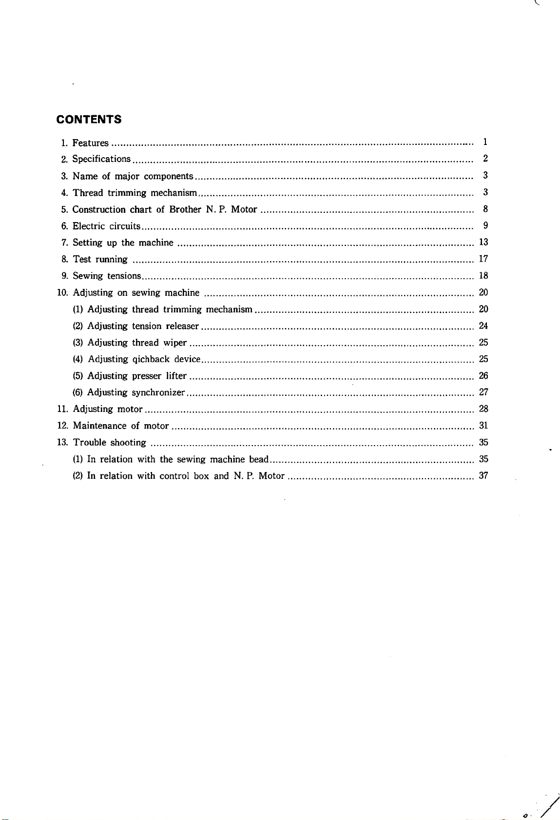
CONTENTS
1.
Features.......................................................................................................................... 1
2.
Specifications................................................................................................................... 2
3.
N arne of major components.............................................................................................. 3
4.
Thread trimming mechanism............................................................................................. 3
5.
Construction chart of Brother
6.
Electric circuits................................................................................................................ 9
7.
Setting
8.
Test running ...................................................................................................................
9.
Sewing tensions................................................................................................................
10.
Adjusting
up
the machine . .. .. .. . .. . . . . . . . . . . .. .
on
sewing machine . . . . . .. . . . . . . . . . . .. . . . . . . . . . . . .
N.
P.
Motor . .. .
..
. . . . . .
..
. .. .. .. . . . .. . .. . .. .. .. . .. .. .. .. . ... . . . .. .. . .
..
.. . . . . . . . . . . .. . . . . . . . . . . . .. . .. .. . .. . . . . . . . . .. . . . .
..
. . . . . . . . . . . . . . . .. .. . . . . . . . . . . . . .
..
. ..
..
..
. . . . . . . . . . . . . . . . . . . . . . . .
..
. . . . .. . . . . . . . . . .. . . . . . . .
..
..
. . . 8
13
17
18
20
(1) Adjusting thread trimming mechanism ..........................................................................
(2)
Adjusting tension releaser . . . . . . . . . . . . .. . . . . . . . . . . . . . . . . . . . . . . . . . . . . . . . . . . . . .. . . . . . . . . . . . . . .
(3)
Adjusting thread wiper ................................................................................................
(4)
Adjusting qichback device ............................................................................................
(5)
Adjusting presser lifter ................................................................................................
(6)
Adjusting synchronizer .................................................................................................
11.
Adjusting motor ...............................................................................................................
12.
Maintenance of motor . . . . . . . . . . . . . . . . .. . . . . . . . . . . .. . . . . . . . . . . .. . . . . . . . . . . . . . . . . . .. .. . . . . . . . . . . .. . . . . . . . . .. . . . . . . .. . . . . . . . . .
13.
Trouble shooting . . . . . . . . . . . . . . . .. . . . . . . . . . .
(1)
In relation with the sewing machine bead.....................................................................
(2)
In relation with control box and
..
. . .
..
. .. . . . . .. . . . . . . . . . . . . . . . .
N.
P.
Motor
.. ..
..
. . . . .. . . . . . . . . . . . . . . . .
..
..
.. . ..
..
.. .. .. . . ..
..
.. . .. .. .. .
..
. . . . . . . . . . . . . . . . . . . . . . . .
..
. . . . . . . . . . . . . .. .. . . . . . . .
..
.. .. .. . .. .. .. .. ....
20
24
25
25
26
27
28
31
35
35
..
.. .
37
Page 4
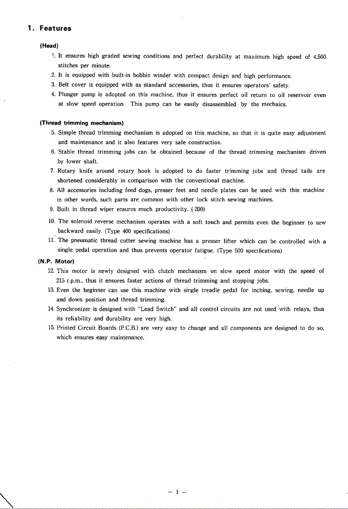
1. Features
(Head)
1..
It ensures high graded sewing conditions and perfect durability
stitches per minute.
2.
It is equipped with built-in bobbin winder with compact design and high performance.
3.
Belt cover
4.
Plunger pump is adopted
at
slow speed operation. This pump can be easily disassembled by the mechaics.
(Thread trimming mechanism)
5.
Simple thread trimming mechanism is adopted
and maintenance and it also features very safe construction.
6.
Stable thread trimming jobs can be obtained because of the thread trimming mechanism driven
by lower shaft.
7.
Rotary knife around rotary hook is adopted to do faster trimming jobs and thread tails are
shortened considerably
8.
All
accessories including feed dogs, presser feet and needle plates can be used with this machine
in
other words, such parts are common with other lock stitch sewing machines.
9.
Built in thread wiper ensures much productivity.
is
at
maximum high speed of
equipped with as standard accessories, thus it ensures operators' safety.
on
this machine, thus it ensures perfect oil return to oil reservoir even
on
in
co~parison
with
this machine, so that it
the
conventional machine.
is
quite easy adjustment
(-200)
4,500
10.
11.
(N.P.
12.
13.
14.
15.
The
solenoid reverse mechanism operates with a soft touch and permits even the beginner to sew
backward easily. (Type
The
pneumatic thread cutter sewing machine has a presser lifter which can be controlled with a
single pedal operation and thus prevents operator fatigue. (Type
Motor)
This motor is newly designed with clutch mechanism
215
r.p.m., thus it ensures faster actions of thread trimming and stopping jobs.
400
specifications)
500
specifications)
on
slow speed motor with the speed of
Even the beginner can use this machine with single treadle pedal for inching, sewing, needle
and down position and thread trimming.
Synchronizer
is
designed with "Lead Switch" and all control circuits are not used with relays, thus
its reliability and durability are very high.
Printed Circuit Boards (P.C.B.)
are
very easy to change and all components are designed to do so,
which ensures easy maintenance.
up
- 1 -
Page 5
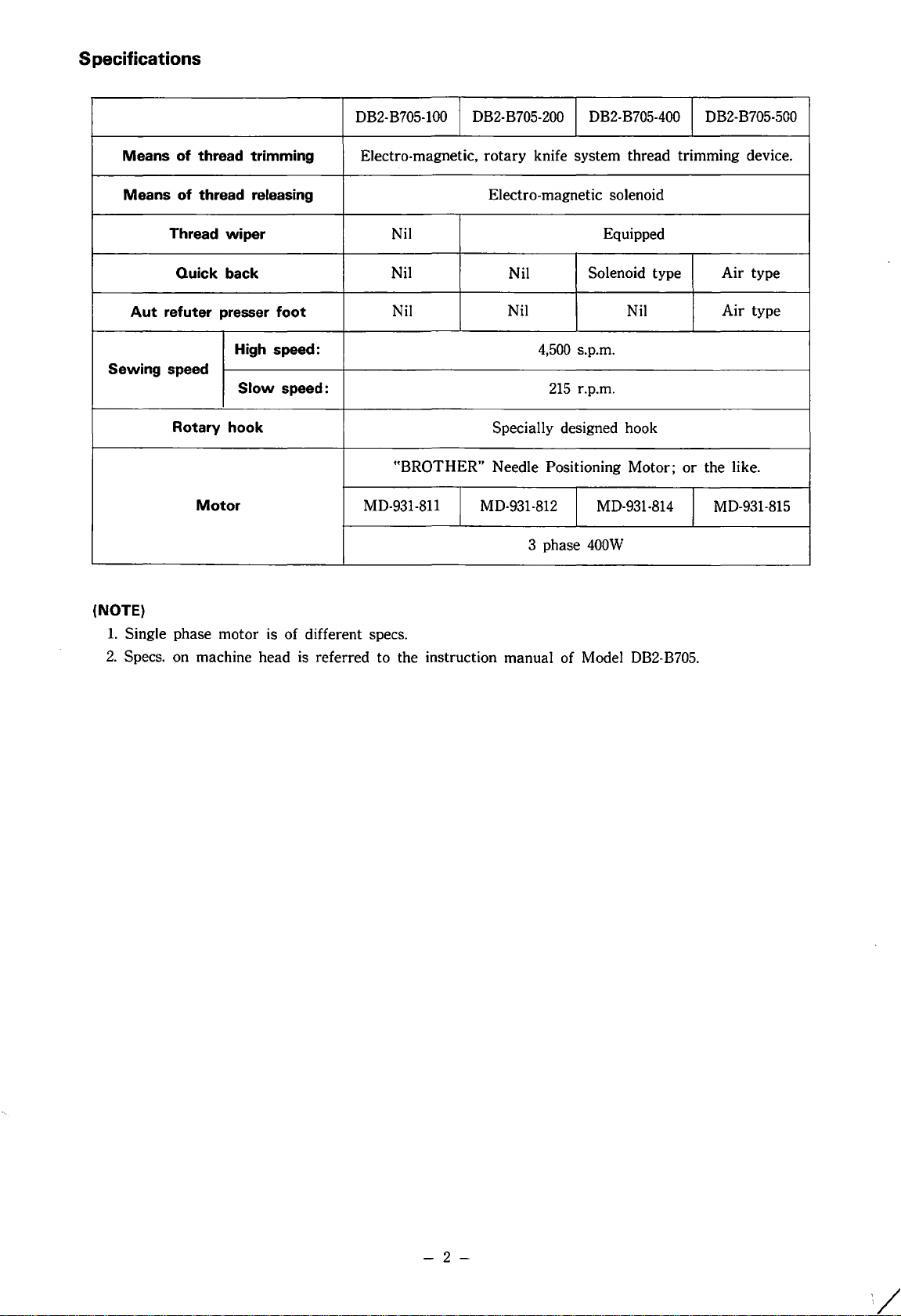
S pacifications
DB2-B705-100 DB2-B705-200 DB2-B705-400
Means of thread trimming
Means of thread releasing Electro-magnetic solenoid
Thread wiper Nil
Quick back
Aut
refuter presser foot
High speed:
Sewing speed
Slow
speed:
Rotary hook
Motor
Electro-magnetic,
Nil
Nil
"BROTHER"
MD-931-811
rotary
MD-931·812
knife
system
Equipped
215
Solenoid
r.p.m.
MD-931-814
400W
Nil
Nil
4,500 s.p.m.
Specially designed hook
Needle Positioning
3 phase
thread
type
Nil
Motor;
DB2-B705-500
trimming
Air
Air
or
the
MD-931-815
device.
type
type
like.
(NOTE)
1.
Single
2.
Specs. on
phase
machine
motor
is
of
different specs.
head
is
referred
to
the
instruction
manual
of Model DB2-B705.
-
2-
Page 6
3.
Name
This machine is componed of the following
components.
(1)
(2)
(3)
4.
Thread
of
major
Head
a.
Head
b.
Thread trimming mechanism
c. Treadle pedal
d.
Tension releaser
e. Synchronizer
f.
Thread wiper (Optional parts for
Control box
Needle Positioning Motor
trimming
components
mechanism
-200)
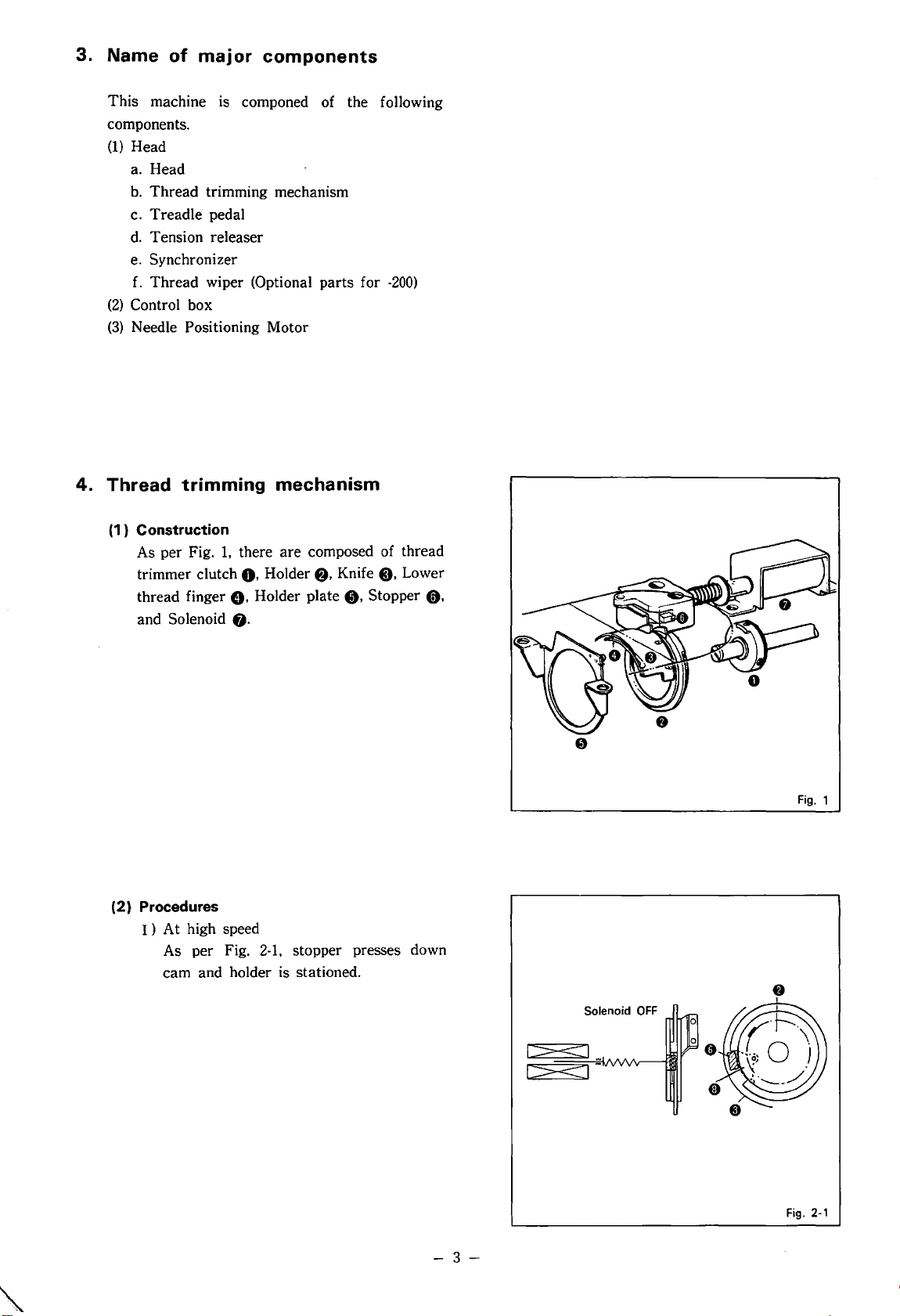
(1) Construction
As per Fig.
trimmer clutch
thread finger
and Solenoid
(2) Procedures
I)
At high speed
As per Fig.
cam and holder is stationed.
1,
there are composed of thread
0.
Holder
G.
Holder plate
fj.
2·1,
fj,
Knife
0.
e.
Stopper C),
stopper presses down
Lower
Fig.
1
1~1-
-
3-
Fig.
2·1
Page 7
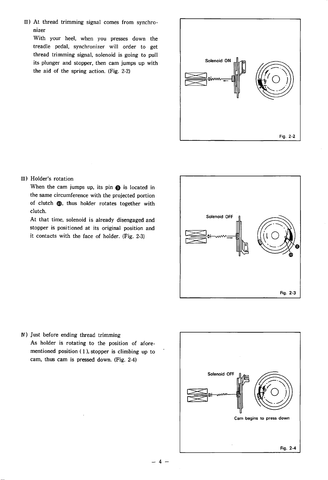
II)
At
thread trimming signal comes from synchronizer
With your heel, when you presses down the
treadle pedal, synchronizer will order to get
thread trimming signal, solenoid is going to pull
its plunger and stopper, then cam jumps up with
the aid of the spring action. (Fig.
III)
Holder's rotation
When the cam jumps up, its pin
the same circumference with the projected portion
(li),
of clutch
clutch.
At
that
stopper is positioned
it contacts with the face of holder. (Fig.
thus holder rotates together with
time, solenoid is already disengaged and
at
its original position and
2-2)
0 is located in
2-3)
I>"<:
I><
I_.
I.
Solenoid
I:>< I ..
OFF
Fig.
2-2
N) Just before ending thread trimming
As holder is rotating to the position of afore-
),
mentioned position ( I
cam, thus cam is pressed down. (Fig.
stopper
is
climbing up to
2-4)
Solenoid
c><L
r><J"'
OFF
0
Cam begins to press down
Fig.
2-3
Fig. 2-4
-4-
Page 8
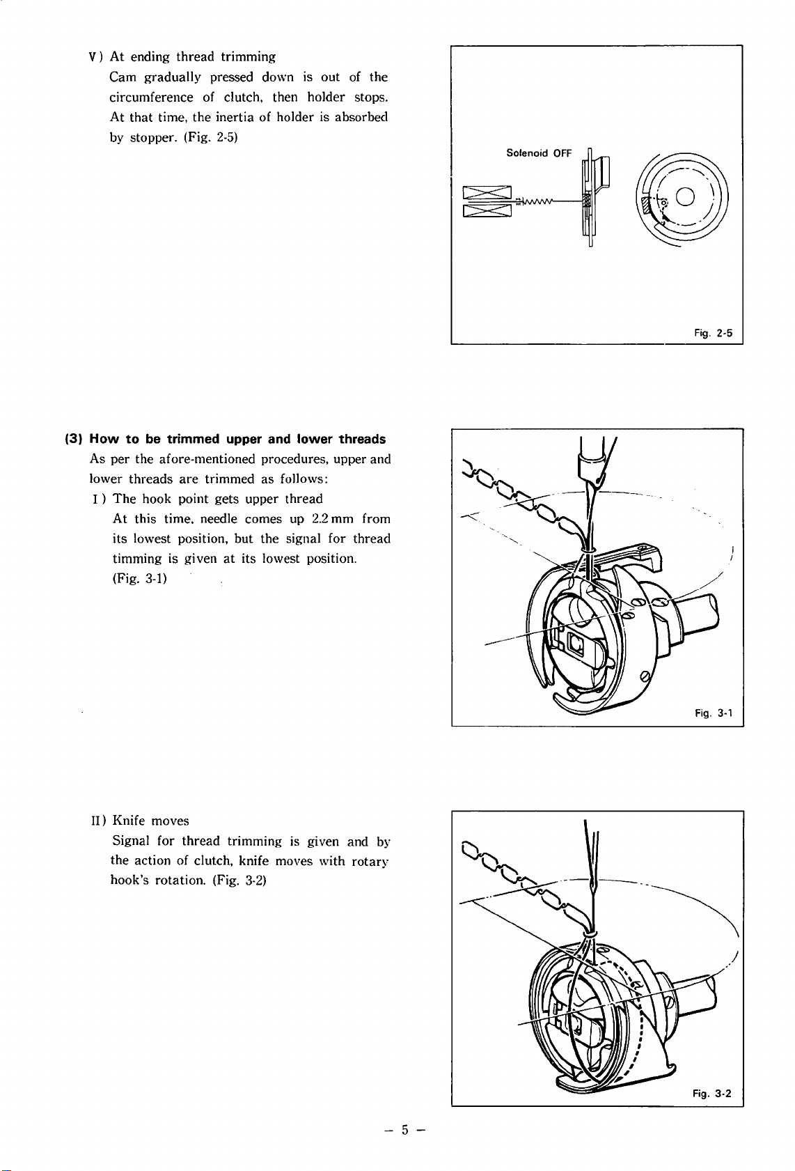
V)
At
ending thread trimming
Cam gradually pressed down is
circumference of clutch, then holder stops.
At
that
time, the inertia of holder is absorbed
by stopper. (Fig.
2-5)
out
of the
Solenoid
OFF
(3)
How
to
be trimmed upper and
As per the afore-mentioned procedures, upper and
lower threads
I )
The
At this time. needle comes up
its lowest position, but the signal for thread
timming is given
(Fig.
are
trimmed as follows:
hook point gets upper thread
at
its lowest position.
3-1)
lower
2.2
mm from
threads
1><1
..
1><:1"'
Fig.
2-5
II) Knife moves
Signal for thread trimming is given and by
the action of clutch, knife moves with
hook's rotation. (Fig.
3-2)
rotary
- 5 -
Page 9
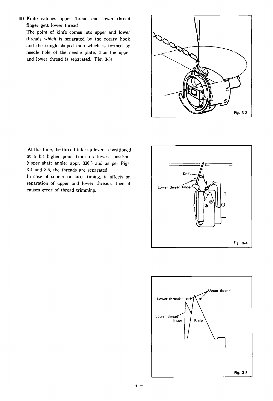
III)
Knife catches upper thread and lower thread
finger gets lower thread
The
point of kinfe comes into upper and lower
threads which is separated by the
and the tringle-shaped loop which is formed by
needle hole of the needle plate, thus the upper
and lower thread is separated. (Fig.
At this time, the thread take-up lever is positioned
at
a bit higher point from its lowest position,
(upper shaft angle; appr.
3-4
and
3-5,
the threads are separated.
In case of sooner or
separation of upper and lower threads, then it
causes error of thread trimming.
330·) and
later
timing, it affects on
rotary
3-3)
as
hook
per Figs.
..
")
Fig.
Fig.
3-4
3-5
-
6-
Page 10
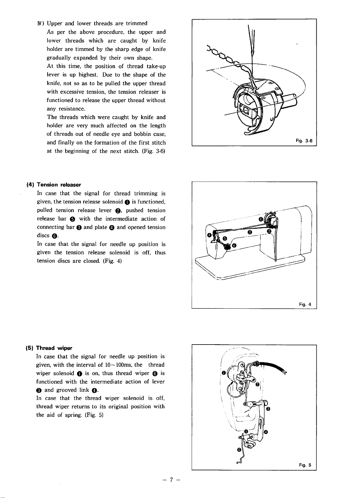
N) Upper and lower threads are trimmed
As per the above procedure, the upper and
lower threads which are caught by knife
holder are timmed by the sharp edge of knife
gradually expanded by their own shape.
At
this time, the position of thread take-up
lever is up highest. Due to the shape of the
knife, not so as to be pulled the upper thread
with excessive tension, the tension releaser
functioned to release the upper thread without
any resistance.
The
threads which were caught by knife and
holder are very much affected on the length
of threads out of needle eye and bobbin case,
and finally on the formation of the first stitch
at
the beginning of the next stitch. (Fig.
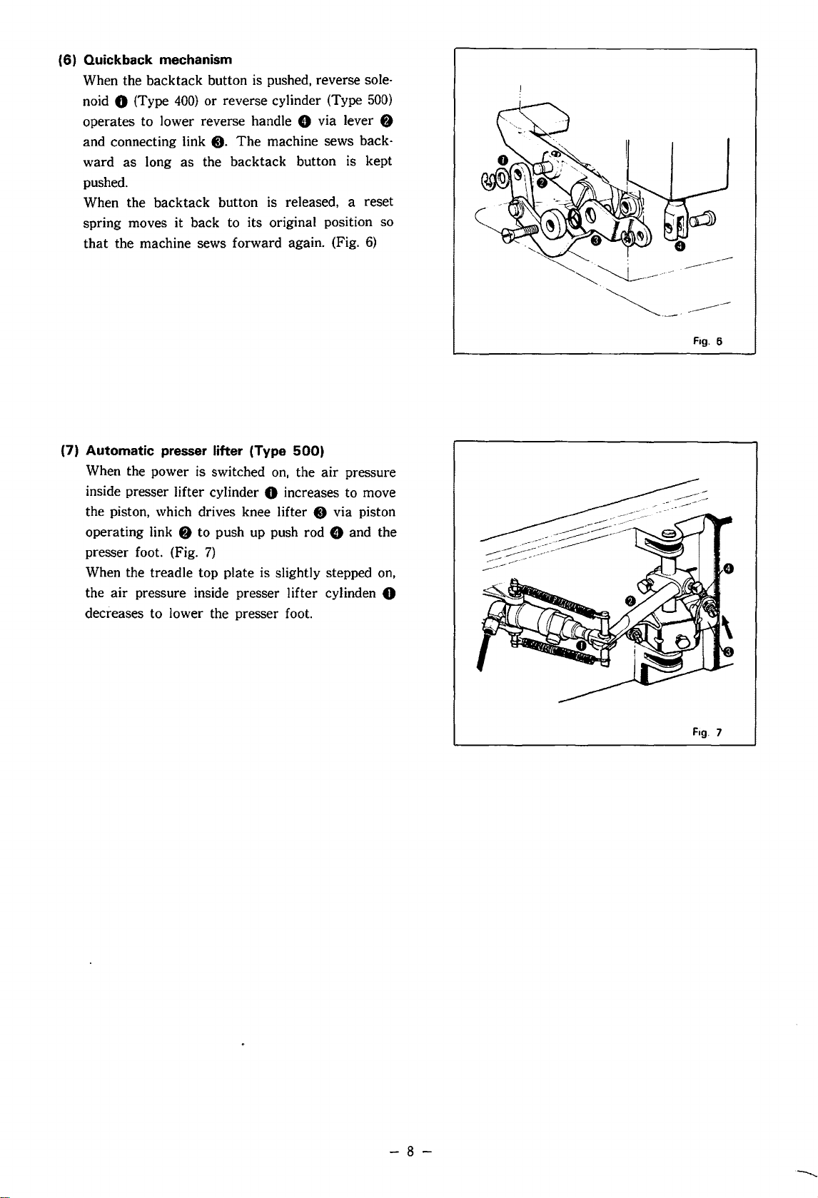
(4) Tension releaser
In case that the signal for thread trimming is
given, the tension release solenoid
pulled tension release lever
release bar
connecting
discs
(t.
In
case that the signal for needle
8 with the intermediate action of
bar
0 and plate 8 and opened tension
0 is functioned,
f),
pushed tension
up
position
given the tension release solenoid is off, thus
are
tension discs
closed. (Fig.
4)
3-6)
is
is
Fig.
3-6
(5) Thread wiper
In case that the signal for needle
given, with the interval of
wiper solenoid
0 is
10-lOOms, the thread
on,
thus thread wiper 0 is
up
position is
functioned with the intermediate action of lever
0 and grooved link
O·
In case that the thread wiper solenoid is off,
thread wiper returns to its original position with
the aid of spring. (Fig.
5)
I>;=~=='
~--......._
Fig.
Fig.
4
5
-
7-
Page 11
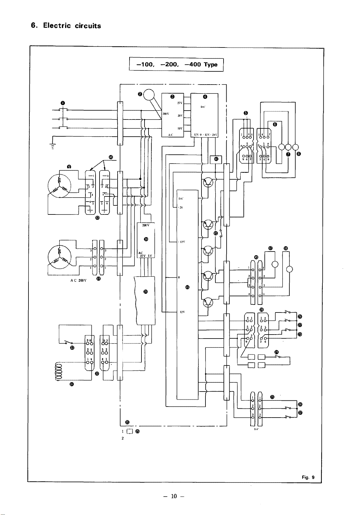
(6) Quickback mechanism
When the backtack button is pushed, reverse sole-
noid
0 (Type
operates to lower reverse handle 8 via lever
and connecting link C).
as
ward
pushed.
When the backtack button is released, a reset
spring moves it back to its original position so
that
the machine sews forward again. (Fig.
long
400)
or reverse cylinder (Type
The
machine sews back-
as
the backtack button is kept
500)
f)
6)
.
---------------
Fcg.
6
(7) Automatic presser lifter (Type
When the power is switched
inside presser lifter cylinder
the piston, which drives knee lifter
f)
operating link
presser foot. (Fig.
When the treadle top plate is slightly stepped on,
the air pressure inside presser I ifter cylinden
decreases to lower the presser foot.
to push up push rod 8 and the
7)
500)
on,
the
air
0 increases to move
8 via piston
pressure
0
Fcg.
7
-
8-
--........
Page 12

5.
Construction
chart
of
Brother
N. P.
Motor
0 Synchronizer
f)
Needle up position
8 Needle
0 Thread trimming
0
0 Main
Slow
down
speed
motor
position
motor
-9-
f)
Clutch lever
0 Brake
0 Clutch
tii)
Switch
CD
Treadle pedal
for
thread trimming
Fig. 8
Page 13
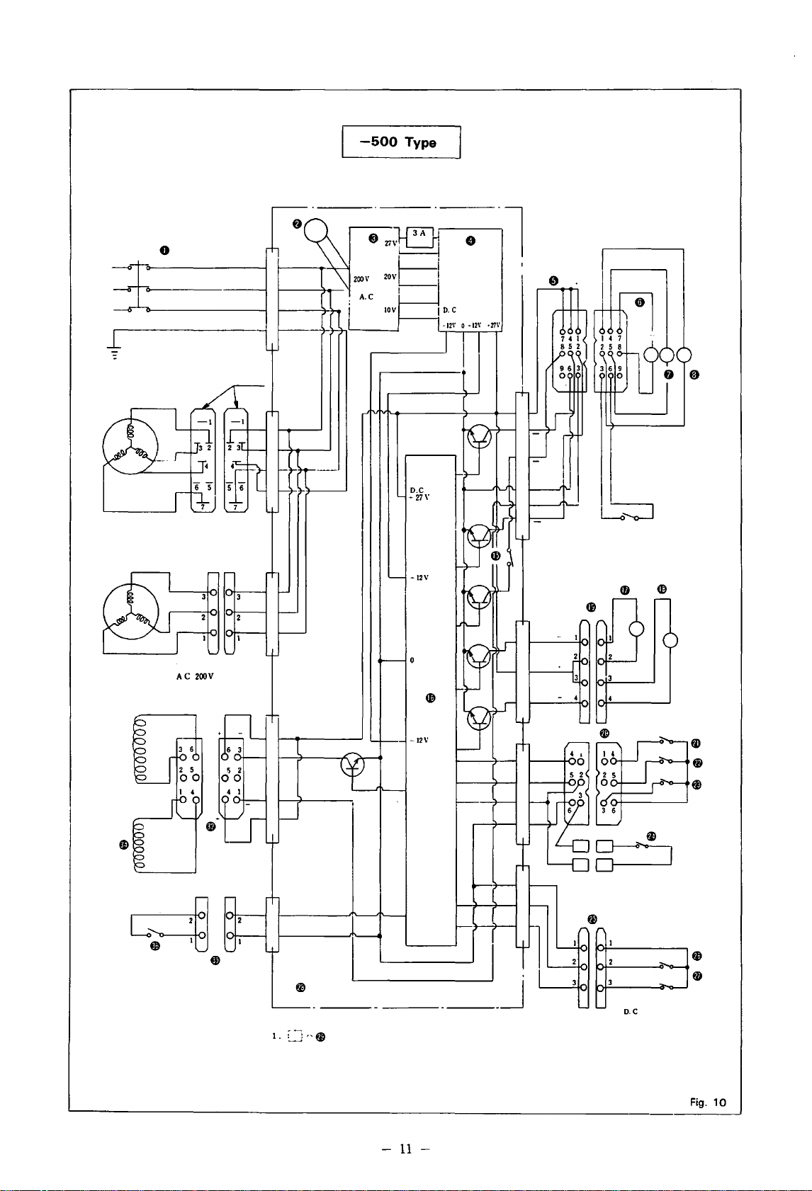
6.
Electric
circuits
0
=±
-
-
-100,
-200,
,\,C
ll.C
• 12\"
-400
12\' 0 •
Type
8
ll.C
12\'.
-l
0
24\'
AC
27V
SV
~--
____
12\'
I
j
11.1"
-
10-
Fig.
9
Page 14
I
-500
Type
I
-
11
-
~
~-
D.C
Page 15
0.
Electric source SW
f).
Pilot lamp
@).
Transformer
8.
P.
C.
B.
for
e.
9P plug
0.
Wiper
coil
8.
Tension releaser coil
0.
Trimmer
C).
Main
tli).
Mark
G).
Fuse
(8. 7P plug
tl). Slow speed
coil
motor
tl. 3P plug
Cl.
Wiper
SW
(D. Logic circuit
$.
Brake coil
C]!).
Clutch coil
electric source
motor
fl). 4P plug
•·
6P plug
fD.
Needle
up
t».
Needle
down
fj.
Trimming
fJ.
Safety
SW
fl). 3P plug
fi.
Micro SW
tj.
Micro SW for trimming
fi.
Control box
@).
Stands
.:I!).
Transformer
i).
P.C.B.
e.
6P plug
1).
Back SW
@).
Back coil
6).
2P plug
~.
Foot pedal
for
for
bushings
for
electric source
SW
high speed
for
control box
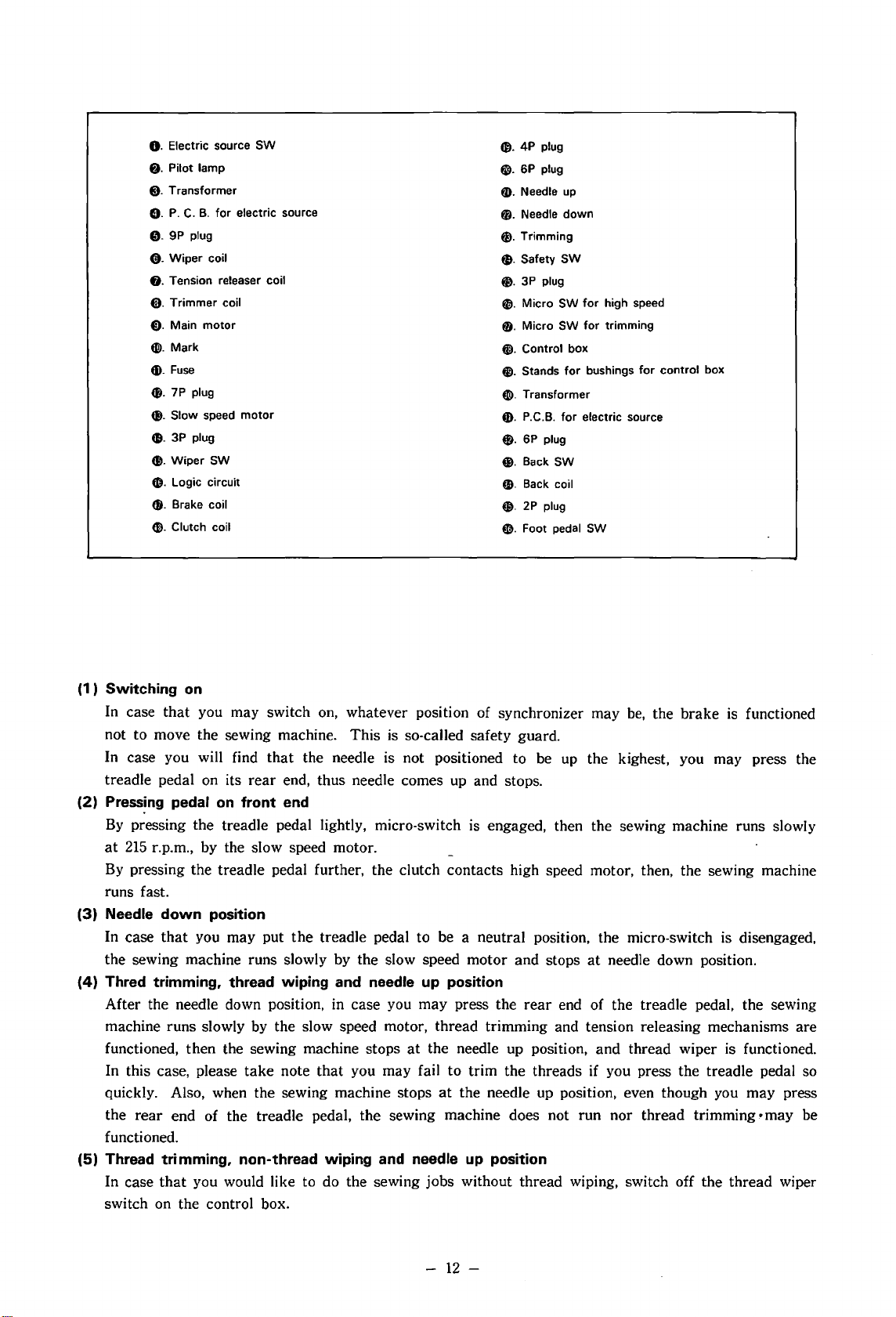
(1
) Switching
In case that you may switch
on
on,
whatever position of synchronizer may
be,
the brake is functioned
not to move the sewing machine. This is so-called safety guard.
In case you will find that the needle is not positioned to be
treadle pedal
(2)
Pressing
By
pressing the treadle pedal lightly, micro-switch
at
215
By
pressing the treadle pedal further, the clutch contacts high speed motor, then, the sewing machine
r.p.m., by the slow speed motor.
pedal
on
on
its
rear
front end
end, thus needle comes
up
and stops.
is
engaged, then the sewing machine runs slowly
up
the kighest, you may press the
runs fast.
(3) Needle
In case
the sewing machine runs slowly by the slow speed motor and stops
(4)
Thred trimming, thread wiping and needle up position
After the needle down position, in case you may press the
down
that
you may put
position
the
treadle pedal to be a neutral position, the micro-switch is disengaged,
at
needle down position.
rear
end of the treadle pedal, the sewing
machine runs slowly by the slow speed motor, thread trimming and tension releasing mechanisms are
functioned, then the sewing machine stops
take
note
that
In this case, please
you may fail to trim the threads if you press the treadle pedal so
quickly. Also, when the sewing machine stops
rear
the
end of the treadle pedal, the sewing machine does not run nor thread trimming • may be
at
the needle up position, and thread wiper is functioned.
at
the needle up position, even though you may press
functioned.
(5) Thread trimming, non-thread wiping and needle
In case
that
you would like to do the sewing jobs without thread wiping, switch off the thread wiper
up
position
switch on the control box.
-
12-
Page 16

7.
Setting
up
the
machine
Setting
refer
the i
(NOTE)
Do
(1)
Motor
r--·
the h
ead
. oil reservoi r.
nstruction manual for l\l
not
hold
the
synchronizer in case you hold
pulley and
50
liz High speed 4,550 4.300
60
I Iz High
V-belt
Slow
speed
spee
Slow speed 215
thread
odel 082-8705.
115
L
-
f-
95mm
d 4.
stand
mm
--
215 200
550
I
on
table
is
M
otor
105mm
exactly
the
sewing machine head.
pulley
100
111111
same
as i\lode l DB2-8705's. Th
95mm
--
4.050 T 3.850
---
190
90
mm
4.300 4.100 3.850 3.550
200 190
85mm
180
-t--
80 mm
-
180
90 mm
3.650
70
1
75m
m
1
65
erefore,
85mm
~
I
I
3,450
-
1
60
(2)
V-belt : 42 inches for 60 l iz
Motor
Ir
(I) Rem
(2) f
(3)
(4) In
(NOTE)
pulley change
you wish
asten sec
Get the prop
instruction manual
If
sition
the
tate
and pu
The pulley
is
recommended
K pulley, although
pulleys are
to
cha n
ove pull
the
case
motor.
bracket
ey
cover
urely the nut
er
tension of V-bell. (See the
tension is
is
not
accurate.
you
may
loosen
fj
ll
rod 0 is right angle.
to
be used
a~plicable.
ge
the motor pulley, p
0 and
of
Model D82-8705).
too
loose, the
change
three
so
that
to
use
the
change
~
-
the
position of
bolts 0 and
clutch
with
this
with
BROTHER
commonly
stop
lever
motor
lease
the pull
po-
ro-
0
sold
take
ey
.J3 inches
note
f)
.
for
50
I-1
z
the followings (Fig. 11)
0
0
Fig.
11
-
13
-
Page 17

(3)
Connection
of
wires
I ) Put the plugs out of sewing machine head
and synchronizer into the table top hole
The wire out of synchronizer should be fixed
f)
on
with wire supporter
the belt cover.
Connect the plugs 8 comes from control
8.
(Figs.
12,
box
II)
To
earth wire
prevent the static electricity, connect the
13)
C) out of table hinge to the
bracket of motor.
III)
Pass the plugs through the hole in the table
and connect them to the plug sockets leading
from control box
0 and treadle 8). (Fig.
box
(A)
plug for Types
(B)
plug for Types
(C)
plug for Type
(D)
plug for Type
(E) plug for Type
(F) plug for Types
C), safety device
13,
Fig.
100,
200,
400,
500
100,
200,
400,
500
400
500
500
100,
200,
400,
500
ct.
14)
O·
valve
Fig.
12
Fig.
Fig.
13
14
·-
14-
Page 18

Ill)
To
connect the
disconnect
over
them
Insert
the
the nul \\'ith your fingers,
nut
once
cannot
(Fig.
be removed when pulled by hand.
18)
air
nut 8 and
the tube end
tube
end in
or
twice with a
tube to the connector, first
sleeve 0
as
shown in the figure.
to
the socket, tighten
spanner
and
and
then
so the
then fit
turn
the
tube
\
3 - 5
mm
-
Fog. 18
(5) Air pressure (Type
(1) Keep
(2)
air
pressure
It can be regulated with the valve box reducing \·alve.
loosen hexagonal
clockwise.
the knob counterclockwise,
tack
button
pressure,
again.
nal nul
If
water coll
compressor
push up
and
After
to
drain
If
If
the
or
then increase the air pressure
its
fix the
ects
to
lower the air pressure
cock 0
500)
at
5kg
em~
± 0.5kg cm
the
air
pressure is too low,
nut 0 and
air
pressure is too high,
the
treadle
regulation. tighten the hexago-
knob
. (Fig.
inside bottle @.
and
turn
operate
to lower the
19)
discharge the water.
2
knob
turn
the back-
air
stop
the
and
then
•
f)
Fog. 19
-
16
-
Page 19

8.
Test
running
Remove the needle from needle bar.
It is vitally important for you to
If
you will find out any troubles, look into the trouble shooting
(1) Switch on and make sure whether pilot lamp is put on, then switch off. At
make
sure each procedure and
take
in
this service manual and
motor should be examined.
(NOTE)
1 .
If
you
will
find
out
that
the
sewing machine
should be changed.
2. This BROTHER Needle Postioning
changing
tor.
nector
3. Green coloured
4.
Do
(2)
Make sure whether slow speed motor runs smoothly pressing the treadle pedal lightly.
(3)
Make sure whether the sewing machine stops
at
the neutral after pressing the pedal
(4)
Make sure whether the sewing machine stops
pedal is pressed
(5)
After making sure all the above procedures, put the needle and
If
you
matching
not
switch
the
position
change
red markings.
wire
on
while
at
the rear.
of
the
position
is earth
you
the
plug located
wire
Motor
of
the
plug,
which
are pressing
at
the front.
rotation
is
not
in
the
motor
motor
should be grounded.
the
treadle pedal. Pedal should be neutral position.
at
the needle down position, when the pedal is positioned
at
the needle up position
is reverise,
featured
body
does
not
start
the following step.
that
either
to
get
reverse
similar
run.
to
BROTHER
Connect
after
knife's rotation, when the
sewing.
take
proper step.
time, the direction of
two
of
three
wires
rotation
the
plug
by
merely
Clutch
with
Mo-
con-
(Treadle Pedal)
Its operation and function is as per Fig.
(NOTE)
1 .
Switch
motor
val,
2.
Do
3.
Switch
sewing machine as
for
4.
Do
switching
5.
Do
plugs
on
and
running
you
may
not
set
the
off
without
adjustment
not
disconnect
on.
not
pull
the
or
terminals.
after
recognition
with a few
take
the
wires
on
fail
well
and repair.
the
wire
to
second
steps.
moving
to
as
plugs
disconnect
check
the
13.
of
the
inter-
parts.
the
motor
while
the
0
•
0.
Lower presser foot.
f).
Low-speed sewing
@).
High-speed sewing
G).
Neutral (Machine stops
down;
presser
foot
0.
Thread cut and removed; machine
stops
with
needle up.
is
raised).
with
needle
Fig.
20
-
17-
Page 20

9.
Sewing
(1
) Pre-tension
tensions
When the threads are trimmed, the upper
tension assembly is released, then the pre-
on
tension is the only tension
If
thread.
tension
you may get the stronger the
on
it, the shorter the upper thread
the upper
out of the needle eye after thread trimming
To
is done, and vice versa.
the thread-off, skip stitching
adjust the tension,
at
the beginning
and thread tail on the top of material can
be eliminated.
The
standard length of thread after trimming
is about
(2)
Upper tension
Upper tension is almost same
B705,
30-35
however,
mm.
(Fig.
21-1)
as
take
note the followings be-
Model
cause of the thread trimming mechanism.
On
I )
the synthetic threads, if you will
loosen the tension, you may encounter
the thread breakage
22-2)
(Fig.
at
the beginning.
DB2-
Fig.
21-1
II)
Make sure the upper thread is given out
of thread stand without much resistance.
(After thread trimming, there causes
at
thread-off
the beginning because of
short upper thread out of the needle eye.)
III)
In case of skip stitches, the upper thread
cannot be trimmed although the lower
thread can
N)
In order to avoid the skip stitch and
upper thread-off
be
trimmed.
at
the beginning, select
the following parts with much attention.
23)
(Fig.
a)
Needle plate;
The
b)
Presser foot;
The
smaller the hole
smaller on the
©.
the better.
points®
the better. But, the thicker thread
#50, use the standard presser
over
foot.
c)
Rotary hook ;
Special hook.
"BROTHER" hook for Model
100
Series.
d)
Feed dog;
Standard feed dogs can be used.
But, the thicker feed dog cannot be
recommended because the knife may
hit the feed dog in case of too thick
feed dog.
& @,
B705-
18
Fig.
22-2
Fig.
23
-
Page 21

(3) Lower tension
In order to prevent the bobbin from idle run, this
machine is adopted with bobbin case with spring.
Bobbin is recommended to be alminium one.
24)
(Fig.
The
recommended winding on bobbin is less than
80%.
The
lower thread must be pulled out of eye of
bobbin case.
The
standard tension of bobbin spring is
How
to
adjust bobbin tension
a. Loosen lower tension adjusting screw 0 and
get
the
tension of adjusting spring to be "0".
b.
Adjust the lower thread tension to turn the
adjusting screw
bobbin case. (Fig.
(NOTE)
*
If
you feel the unevenness to pull the thread
out of bobbin case, correct the shape
tension spring.
*Incorrect
following troubles.
a. In case of excessive tension; lower thread
will
jam
run.
b.
In case of weak tension; not properly
trimmed with the knife.
Recommended lower thread tension;
To
obtain the above range of
in total, adjust the lower tension adjusting
screw
bobbin spring.
after
8 putting
25)
tension of the bobbin case causes
in the bobbin case due to idle
completion of adjustment of
the
bobbin into the
10
to
5-10
gr.
of
10-25gr.
25
grams
-
Fig.
Fig.
24
25
-
19-
Page 22

1
0.
Adjustment
( 1 ) Adjusting thread trimming mechanism
on
sewing
I ) Changing knife
Firstly, remove dust cover
stopper guide. After completion, make
sure to fix it for safety sake.
Then, remove needle plate, and
needle's lowest position, push stopper
with your finger as per Fig.
Turn
the pulley and get the position so
as
to loosen flat head screws for knife.
(Fig.
27)
machine
0 from
at
26.
the
f)
Fig.
26
Change knife 8 by loosening flat head
screws
C). At
only although
0 are removed. (Fig.
finger
Spacer
thickness
Needle plate
washer thickness
that
time, change the knife
spacert)
and lower thread
28)
Standard
Thick material
Standard
Thick material
0.5mm
0.7mm
0.2mm
0.5mm
Fig.
Fig.
27
28
-
20
-
Page 23

To
set the knife correctly, let the point of knife
meet with needle, turn the pulley reversely and
make
sure the point of
the centre
Also
lower
rotary
cotton
After completion, turn the pulley
get the knife positioned
II)
Adjusting knife holder
In
case
the holder
remove holder
Adjust the position of holder
holder moves smoothly without n}uch clearance.
After completion, fasten the screw securely.
(Fig.
axis
of the needle
make
sure
the clearances between knife and
thread
30)
finger, and lower thread finger and
hook must be averaged about
thread'
that
pass without any resistance.
you may remove knife holder
about
half rotation, and
bracket
knif~
as
at
its beginning.
0.
then holder.
may
contact
per Fig.
toward
at
this position,
bracket
that
you and
so
with
29.
of # 8
8.
turn
that
_--l:il--------
----
------
I
lr
Neeedle
N
11\
1
Knife
)
Fig.
29
III) Adjusting
Loosen the slit so
be 4mm. (Fig.
stopper
31)
that
the
stroke
of stopper
may
Fig.
Fig.
30
31
-
21
-
Page 24

When fixing stopper guide, firstly fix solenoid
temporarily, and fix it onto the bed. Then, bring
the needle down to its lowest position and push
the stopper with your finger to its fullest extent,
and turn the pulley slowly toward you, and
sure
that
the holder begins to move, stopper drops
into the recess portion of holder, pawl
ratchet
on holder
bracket
drops into the first
make
0 of
second tooth of knife holder, and stops. (Fig.
If
knife holder drops prior to the correct position,
fasten stopper guide
tioned far from lower shaft. (Fig.
em>
so that it may be posi-
33)
or
32)
IV)
Adjusting solenoid for thread trimming
Fix
solenoid so
Fix stopper guide so
that
its
stroke
that
the left surface of stop-
may be 3.5mm.
per may be in contact with ® surface of holder
bracket.
Then,
your finger, and you
the
in
stroke
case
that
you may push the stopper by
get
of solenoid is kept
0.5mm
as
per Fig34,
as
correct, 3.5mm.
Fig.
Fig.
33
34
-
22
-
Page 25

If. on the con
sc
re\\'s
the
and
if
that
the stopper is
\\·hen
you
so
len
oid
V)
i\cljusting clutc
It is dete
get c
orr
If
you
remove the needle pl
adjust
clutch
p
ull
ey
i
nto
the h
that the centre
\\'hen
nex l to
trary. thi
for
solenoid
small.
tO\\'c
to
push i l \\·it h yo
nw\'in,g
h
rmi
ned by the pos
ect
timing of
ing
hole
Hcl yo
ole
and
of needle meets
A h
s stroke
righ
t.
In
returned
it left
or rig
thr
ead t
s as per fig.
u.
put the hexagona I spann er
get the
ole
meets
is too big. loosen
Q)
and mo\·e
this
case.
\\·ith its spr ing
ur
fi
ngcr. you fi
ht. (Fig.
iti
on
of clut
rimmin
ate
. you m
:25. Turn
position
\\'ith hook
hole
a. (
it
makin
35)
g.
ay
of clu tch so
Fi
to
g sure
action
:-;
ch ®
find ou t
ing the
point.
g.
36)
left.
the
to
Fig.
35
In case
and
D.
in
to
B.
get
the correct
Then.
of
adj ustment. loosen
and
lastly
sere\\'
and turn
fasten three scrc\\'S
ing
the pulley
timing
of needle and
at
first
~.
putting
siO\dy
securely. (Fig.
the spanner
to\\·ard
hook poin
scrc\\'s c
~·ou.
37)
Fig.
36
t.
Fig.
37
-
23
-
Page 26

(NOTE)
1.
In
the
ting
the
jected
in
up,
pin,
tion
hit
on
2.
In
knife
missing
case
of
knife
trims
excessively
angle
between
portion
this
result, prior
projected
clutch
of
the
the
knife.
this
adjustment.
case
of
will
of
setting
threads
~
portion
will
lower
So
setting
function
thread
prior
prior
to
pin
4D
of
clutch
to
function
shaft
that,
(Figs.
after
later, thus
trimming
to
correct
in
advance.
correct
of
the
pin
of
clutch
after
and
please
38 & 39)
correct
cam
is
's
needle
.
timing
timing,
and
so
small,
climbing
passes
one
be
careful
timing,
it
causes
Set-
pro-
rota
will
,
-
Fig.
38
(2)
Adjusting
tension
1 ) Adjusting ten sion re
Fix
tension rel
that
time,
sion rel
at
\\'hen
ease
the lo
west
fixing tension rel
of tension rel
the end
of
II) Adjusting t
\\
'hen soleno
so that
ther
tension discs. also when
tione
d.
make sure that the space do
exi
st
bel ween two tension di
releaser
leas
e solenoid
ease sol
seeing
Je,·
from
er
f)
eno
rear
so
id
0 on the
cover.
that
it is position
when you turn it clockwise.
ease Je,·e
ease lev
solenoid
ens
id
e exi
er
sho
uld
be
shaft.
8.
(Fig.
ion
releaser
is functioned . set the
sts
lmm
space
sole
noid is
scs
.
bet\\·een
arm.
fasten ten -
r.
side
face
in
I ine ,,.i th
40)
collar
not
func -
es
at
ed
0
two
not
Fig.
Fig.
39
40
-
24-
Page 27

(3) Adjusting thread wiper
1)
Fix thread wiper solenoid 0 with face plate.
that
At
tioned equally against horizontal shaft. (Fig.
time. fasten solenoid link 8 to be func-
41)
Fig.
41
(4) Quickback device assembly
I ) Fit connecting link 0 over reverse handle
8.
shaft
the order shown in the figure.
II) Connect the lever to plunger
Ill)
N) Backward stitches can be adjusted to a shorter
V)
and assemble lever 8 with the arm in
plunger into the reverse solenoid which is
mounted on the base, and then install the base
on the arm. (Type
Install the cylinder support, to which the reverse cylinder has been attached, on the arm.
Assemble the lever and reverse cylinder
together. (Type
length than forward stitches with the reverse
stopper.
When stopper knob
wise,
backward
If
backward stitches must be adjusted so short
as
to require loosening the stopper knob
almost out of contact with screw
nut
f)
and tighten the screw from under the
bed. (Fig.
43)
400)
500)
0 is turned counterclock-
stitches will become shorter.
(Fig.
and
adjustment
in
e.
42)
Insert the
0.
8
loosen
Fig.
42
-
25
-
Fig.
43
Page 28

(5) Automatic presser lifter assembly and adjust-
ment (Type
I ) Connect presser lifter cylinder
operating link
II) Position knee lifter 0 with push rod 0
lowest position, and tighten knee lifter
500)
0 with piston link coupling
f)
and piston
in
cou-
pling e with the piston inserted all the way
into the cylinder.
III)
Adjust knee lifter stopper
presser foot
N) A delay device
will rise 8
is
provided so that the presser
mm.
fj
so that the
(Fig.
44)
foot will rise after the threads have been cut.
VR-3
Delay time increases when
is
turned clockwise. (See
box
V )
If
the presser foot rises before the thread
the control
11.3.)
wiper returns to its original position, the
needle may interfere with thread wiping.
The
valve box has an adjuster for regulating presser rising speed. When its knob is turned clock-
wise, the speed decreases. (Fig.
VI)
The
tension of treadle top plate 0 can be
45)
adjusted by regulating the tension of pull
CD>
spring
spring hook
by moving
0.
If
is too great, the machine will
in
or
out treadle pull
the treadle top plate tension
start
running
before the presser foot lowers fully.
If
the tension is too small, the presser foot
will not rise.
VII)
Adjust the position of microswitch
CD
so
that
it will be OFF before the top plate contact
the treadle.
tB
Top plate adjusting screw
adjusting the travel of the top plate.
is used for
If
it is
too small, the presser foot may not rise
cause the microswitch may not be closed
when the top plate is released. (Fig.
46)
0.
the
be-
li
L.)
Fig.
Fig.
44
45
-
26
-
Fig.
46
Page 29

(6) Adjusting synchronizer
Follow (Fig.47)to disassemble and assemble.
Fig.
47
Fix synchronizer with its supporter
1) Adjusting position of thread trimming signal
of
Adjust the position
that
lead switch
the needle
bar's
thread trimming signal so
f)
is in line
lowest position.
\·vith
The
as
per Fig.
magnet 0
adjustment
is made by moving the position of lead switch.
49)
(Fig.
48.
at
Fig.
48
-
27
-
Fig.
49
Page 30

2)
Adjusting position of needle down signal
vVhen
the sewing machine stops
position
neutral position, adjust to move the position of
needle down lead switch
so
set screw and the surface of needle plate may be
16-22mm.
obtained by turning it clockwise and the lower,
counter clockwise.
after
high speed sewing and treadle pedal's
0 by loosening its screw
that
the distance from the lower part of needle
(Fig.·
50)
The
3)
Adjusting position of needle up signal
\Vhen the sewing machine stops
needle
sed down
the position of needle up lead switch
up
position
by
your heel. adjust to move
(Fig.
49)
by loosening it screw so
the distance from point of needle and top
surface of needle plate may be
(Fig_
51)
at
its needle down
higher position will be
after
treadle pedal pres-
7 -lOmm.
at
its
8
that
--·
-------
16-22mm
_
.....
--·
Fig.
50
7
-10mr•
11.
Adjusting
(1)
Adjusting clutch play
After long usage of the motor causing
of clutch lining, thus the play becomes too
large, adjust it as per following procedures.
(Fig.
1)
Loosen nut
2)
Pull clutch lever downward and adjust the
play to be 0.8-1.2mm fastening clutch adjusting screw
screw
3)
After adjustment is over, lift clutch lever
upward, fasten screw
O. then fasten screw
4)
Make
the lever
5)
It is not necessary to adjust micro-switch
on this adjustment.
motor
52)
0.
can
screw 8 and
8.
get
lmm
The
play to
0.
clutch adjusting
rotate
f),
lock with nut
0.
sure the play is existing by moving
up
and down.
it
wear
360°.
-
Fig. 52
28
Page 31

(2)
Adju
I)
In
case t
you
r fee l
by
pressing
Loos
Fa
sten bolt 0 .
it.
the lighter.
Aft
er
bolt
Adjusting treadle pedal
Y
ou
can get
be
matched
so on.
an
gle
and
making sure clutch l
the most
with you on its weight.
In
this
case.
do adjustment on
positio n of treadle pecl<
ever
straightecl. (Fig. 53)
sting weight
hat
on
en nut 0 and
adjustm
f)
. (
Fig
at
slow
you
may gel inching
the
tread
it
lightly
as
adjust b
the
hea\
ent
is
over. fas
. 54-1)
speed sew
le pe
per
·ier
suit
able
and
by
dal
or
follO\\·ing
olt
f)
.
the
weight: and l
ten
nul 0 not
condition to
play
ll after
pull
rod
to
ing (inching)
merely pu
may
not
procedu
to mo\·e
and
the
be
lling
gel
res.
oosen
Fig.
53
it
2)
Adjusting
L
oosen nut 8 and
Fasten
it.
bolt 0 . th e h
the lighter. (Fi
weig
ht
at
g. 54-2)
thre
adjust
eav
ad
ier
trimmin
bolt
0 .
the
weight: and l
Fig. 54-1
g
oosen
Fig. 54-2
-
29-
Page 32

3)
Adjusting play
Loosen nut
Fasten bolt
the larger. (Fig.
The
bolt 0 can get
at
thread trimming
0 and adjust bolt
0.
the smaller the play; and loosen it,
0.
54-3)
1.8mm
play to rotate
the end of the lever.
At this adjustment, adjust the position of
switch
(3) Adjusting control box
as
well. (Refer Page
1)
Adjusting needle down position
33)
In case of irregular stoppage
at
needle down
position, or sewing machine runs
ously
at
slow speed without stoppage, ad·
just the timer
a. Remove
b.
Turn
VR-1
in
the control box. (Fig.
rear
lid of control box.
0 clockwise on Printed Circuit
Board.
Switch on, and press lightly the treadle
c.
pedal and set it as neutral.
that
At
ously
d.
At the above condition, turn
time, sewing machine runs continu-
at
slow speed.
VR-1
clockwise very clowly, and you will find
out the position where sewing machine
at
stops
VR-1
Switch off and put
e.
the needle down position, then turn
about
300.
counter-clockwise.
rear
lid onto control
box.
2)
Adjusting thread wiper
rear
a. Remove
b.
Turn
VR-2
lid of control box.
f)
clockwise and after needle
up position and time to begin to operate
the thread wiper becomes longer.
Also turn
VR-3 8 clockwise and after
thread wiping job and time to return the
wiper becomes longer.
Accordingly, to adjust the timing of two
regulators, you can get the most suitable
timing of thread wiper.
In case you may not need to wipe off the
thread, switch off switch
(NOTE)
To adjust regulators
VR-3,
careful not
those regulators.
with
screw driver, please be
to
touch anything except
8.
VR-1,
continu·
counter-
VR-2
360°
micro·
55)
and
at
Fig.
Fig. 55
54-3
-
30
-
Page 33

12.
Maintenance
( 1 ) Change of micro-switches
1)
Micro switch for inching
a.
Loosen screw 0 and remove micro switch
8 out of clutch lever.
b.
Pull out terminals 8 and relace switch.
Loosen nut
and adjust
c. Switch on, and
8 pressing by your finger, then sewing
bolt
machine runs slowly.
d.
Detatch your finger, turn bolt
and fix it by nut
2) Micro switch for thread trimming
a. Loosen screw
tioned-above. (Same micro switch is used
both for inching and thread trimming).
b.
Loosen nut 8 and bolt
c. Switch on, press the treadle pedal light
and get it
Press down the treadle pedal by your heel
after
@)
slowly pressing it
Fig.
42,
120°,
d. Detatch the treadle pedal and turn bolt
about
(Fig.
0,
in
at
needle down position, then fasten bolt
and sewing machine moves about
and gets needle
120°
and fasten. it with nut
57)
of
motor
unscrew bolt
the following manner.
as
per Fig.
0.
(Fig.
8.
41,
fasten slowly
56)
0 and replace it
@).
neutral position.
by
your finger
up
position.
fix switch
180°
further
as
men-
as
per
8.
@)
Fig.
56
Fig. 57
(2) Changing linings
In
case you replace the parts,
please clean up every points.
1)
Changing
slow speed motor.
a. Remove screw
••
b.
Remove bolt 8 and replace
brake
selation
c.
To
fix it, put the end of
spring
of
brake
end of spring into the hole
of spring fixture
45°
as per Fig.
bolt@).
brake
disc for
0 and cover
disc 8 together with
8.
0 into the hole 8
disc and another
8 and turn
58,
and fasten
-
31
-
Fig.
58
Page 34

2)
Changing clutch plate for slow speed motor
a. Detatch the plug out of slow speed motor
0 as per Fig.
wire
b.
Loosen screw
c. Loosen flat head screw 8 and replace clutch plate
f)
and remove slow speed motor
59.
8.
Fig.
59
••
d.
In
this case, replace friction disc 0 and selation
8.
as
well, by loosening screw fi). (Fig.
To
assemble it, take steps
ble,
at
that time, it
clearance.
e. Install clutch plate
f. Insert one end of spring
retainer
0 and the other end into the hole in disc
is
0 with screw
as
reverse to disassem-
unnecessary to adjust the
CD>
into the hole in spring
60)
8.
0 on the other side, and then attach them to the
motor shaft.
g.
The
hole in disc 0 is about
elliptical end of the motor shaft (Fig.
0 about
disc
(Fig.
60-2)
h.
Insert the spline shaft, and tighten washer m with
fi).
screw
i. Install motor 8 with screws
j.
Insert auxiliary motor cord plug 0 into the plug
socket. (Fig.
*No
clearance adjustment
60"
counterclockwise and fix it.
60)
60"
a way from the
f).
is
necessary.
60-1),
so turn
'
'
_>
..................
~--
----
------
......
--
__
~
-~~-
~
Fig.
60
(NOTE)
1.
Spring
spring
former.
2.
When replacing the spline shaft, replace also
the disc.
tD
so
is
wound opposite
the
latter eannot be
to
the brake
used
for the
-
32
-
Fig. 60-1
Fig.
60-2
Page 35

(4) Changing lead switch
a. Remove cover and pull out the terminal
b.
Remove screw 8 and replace lead switch
c.
To
put the terminal 0 must be done with red
wire to be sewing machine pulley. (Fig.
(NOTE)
Do not knock or drop LEAD
to
give extra-ordinary shocks.
0.
C).
64)
SWITCH
. Fig.
64
-
34
-
Page 36

13.
Trouble
shooting
(A) In relation with the sewing machine
(1)
Fail
to
trim the threads.
a. Both threads
CAUSE:
are
caught by knife
Knife is not sharp enough.
( I ) Flaw on the knife.
ADJUSTMENT:
CAUSE:
ADJUSTMENT:
CAUSE:
Replace
(II)
Knife is worn out.
Replace
(III)
Incorrect setting the knife, especially check the space between knife and lower
thread finger.
ADJUSTMENT:
b.
Upper thread
Remove lints
Is
trimmed but comes out of needle eye
or
trimmed.
CAUSE:
Incorrect setting of the knife.
the needle.
ADJUSTMENT:
(I)
Fasten securely two flat head screws for knife. (See
CAUSE: Incorrect position of the lower thread finger.
ADJUSTMENT:
Make
sure the clearances between knife and lower thread finger is 3mm.
(See Page
23-
29)
c. Upper thread is not trimmed.
head
dusts and/or replace.
The
point of knife should be
at
the beginning
or
lower thread is not
in
the centre axis of
Page
20-21)
CAUSE: Out of timing the knife.
ADJUSTMENT:
d.
Needle
breaks
CAUSE:
ADJUSTMENT:
Correct it. (See Page
at
the beginning.
of timing the thread trimming signal.
Out
19
V)
) .
At the needle's lowest position, get the synchronizer magnet
switch for thread trimming.
(See
Page
27-28
(6))
e. Knife does not move.
CAUSE: Solenoid does not function.
ADJUSTMENT:
f.
Thread
trimming signal functions properly, but knife does not move.
CAUSE: Out of adjustment
ADJUSTMENT:
( I ) Make sure
(II)
Check the circiut (See Page
(III)
Adjusting of knife stopper (See
that
you press the treadle pedal by your heel.
41
(13))
Page
21-23,
on
thread trimmer knife stopper.
Fig.
Adjust knife stopper to get 3.5mm clearance by pushing it by your finger.
(See Page
22
N)
g. Knife does not trim the threads sharply and abnormal noise comes from
CAUSE: Knife does not move
( I ) Incorrect setting of knife stopper.
ADJUSTMENT:
Readjust two fastening screws for stopper guide
holder detanches so quickly.
CAUSE:
ADJUSTMENT:
(II)
Heavy movement of holder.
Adjust the fixture of holder
360°.
(See
bracket
Page
21
so
as
contact between clutch and
III)
that
holder moves without much re-
sistance.
CAUSE:
ADJUSTMENT:
(III)
Too
early timing of needle up position.
Delay the timing a little. (See Page
27-28
(6))
31,
rotary
32, 33,
in
line with lead
34,
35)
hook.
-
35-
Page 37

h.
When removing the materials, you feel resistance.
CAUSE:
ADJUSTMENT:
i . Lower thread is not trimmed.
CAUSE: Incorrect
ADJUSTMENT:
Upper thread is not trimmed.
j .
CAUSE: Skip stitch on the final stitch.
ADJUSTMENT: ( 1)
CAUSE: Improper setting the hook position bracket.
ADJUSTMENT:
(2) Thread-off at the beginning.
a. CAUSE:
ADJUSTMENT:
b.
CAUSE:
ADJUSTMENT:
c.CAUSE:
ADJUSTMENT:
d.CAUSE: Incorrect combination on thread and needle size.
ADJUSTMENT:
e.
CAUSE: Position of the knife and the flaw on it.
ADJUSTMENT:
f.
CAUSE: Timing of the knife.
ADJUSTMENT:
Upper thread for the
It prevents smooth movement of the knife, therefore, get stronger tension on the
pre-tension. Especially, in
recommended to be about 30mm.
rotary
Use special
Set the needle correctly.
(II)
Get the smaller
(III)
Adjust the needle down position. (See
Adjust the position of
you put the machine head on the head rest.
Thread
Check the circuit. (See
Too
small opening on tension discs.
Check the position of tension release lever. collar and upper tension regulator,
and get the correct positions.
Too
high the position
Get weak tension, also check the thread passes
the upper thread.
In
case of thinner thread against needle size, it causes such a trouble, then,
check the size.
Needle
#7-9
#
11-14
#
16-18
In case
eye.
In
the upper thread out of the needle eye.
Advanced timing of the knife causes too short thread out of the needle eye, thus
check the timing of clutch.
rotary
release solenoid does not function.
of
existing flaw on the knife, it causes the sf1orter thread
case of improper position of the knife causes thread trimming even on
next
stitch is so long.
case
of thick thread, the thread out of needle eye is
hook is used.
hook, for BROTHER 8705-100 Series.
stroke
Thread
#
#80-50
#40-20
of thread take-up spring.
rotary
Page
at
100-120
hook position
41
(13))
the needle up position.
(See
Page
Page
Check it, adjust
23
V)
28
Fig.
bracket
in
order to
50)
to be the downmost when
get
smooth supply of
out
of
the
needle
or
replace it.
(3)
Skip stitch
a ·CAUSE:
ADJUSTMENT:
b. CAUSE: Improper usage of needle, plate and presser foot.
ADJUSTMENT:
at
the
beginning.
Too
short
thread
Get the proper length of thread. (See Page
Use correct ones. (See
out of the needle eye.
Page
18)
-
36
-
18)
Page 38

c. CAUSE:
ADJUSTMENT:
d.
CAUSE:
ADJUSTMENT:
e.CAUSE: Knife is not
ADJUSTMENT:
(4)
A bad thread wiper
a.
Thread
CAUSE: Operating time too long.
ADJUSTMENT:
CAUSE: Presser foot is automatically raised too soon.
ADJUSTMENT:
b.
Thread
CAUSE: Uper thread too long.
ADJUSTMENT:
CAUSE: Cloth and presser foot have too
ADJUSTMENT:
CAUSE: Operating time too short.
ADJUSTMENT:
CAUSE:
ADJUSTMENT:
wiper hits needle and will not return.
wiper cannot remove upper thread from work.
Lower thread does not come up.
lnproper usage of bobbin and bobbin case.
When the thread trimming is done, bobbin runs idly
length of the lower
Get the proper spring action of the bobbin case to be
Also use alminium flat sided bobbin.
Shape of
In
to catch the lower thread.
case the upper thread loop fails to catch the lower thread.
Excessive oil supply to the
thus
Get the little oil flow to the rotary hook.
In
too excessively by the knife movement, thus it causes idle running
case.
Adjust operating time.
Adjust presser foot operating time.
Adjust pre-tension
Replace presser foot with one having.
Adjust operating time.
Thread
Adjust operating time.
rotary
case of improper shape of the
same
trouble
sharp
case of dull knife. when thread trimming is done. the lower thread is pulled
wiper operates too soon, wiping thread before tension disc closes fully.
thread is shortened.
hook and oil to the hook.
The
lower thread is wound into the hook in which
as
above
enough.
rotary
hook causes the lower thread stick to the hook,
\Vill
cause.
great
(See Page
rotary
resistance.
hook, especially on the point of groove
19)
in
the bobbin case, thus the
5-10
grams.
in
the bobbin
NOTICE ON CHECKING MOTOR AND CONTROL BOX
1.
Make
sure to switch off when you plug in and off.
2.
On
Blue plug, the voltage on this circuit is very low, then it is not so dangerous even though you may be
short circuit.
3.
To
check the resistance on Blue plug, please use the tester with X
avoid troubles on various switches.
4.
Check the voltage ONLY on White plug out of control box.
5.
To
check the resistances on White plug and others, please use the tester with X 1 Ohm Range.
6.
To
check the circuit with the tester, running the sewing machine, it
a slight movement.
7.
Switch off when you may remove the
8.
To
replace Fuse,
make
sure to use 3A's.
rear
lid of the control box.
-
37
-
1000
Ohm Range
is
alright for the circuit if tester shows
or
more,
in
order to
Page 39

1 )
Motor
a. CAUSE: No electricity puts
ADJUSTMENT:
b.
CAUSE: Out of function on switch
ADJUSTMENT:
c.
CAUSE: Out of order on pilot lamp.
ADJUSTMENT:
2)
High speed motor does not run.
does not run. Pilot lamp
Check the electricity by the tester.
Check the circuits by the tester.
Replace.
on
the control box
in.
and/or
is
off.
wires.
a. CAUSE: Incorrect adjustment on the clutch spacing.
ADJUSTMENT:
( I ) Press the threadle pedal on the front without electricity and turn the sewing
machine pulley by hand. Running smoothly is right.
(II) Make sure the play on the treadle pedal to be 7mm
b.
CAUSE: Incorrect or imcomplete plug-in on high speed motor.
ADJUSTMENT:
c.
CAUSE: High speed motor runs as single phase.
ADJUSTMENT:
d.
CAUSE: Mal-winding on motor.
ADJUSTMENT:
( I ) Plug should be inserted with red marking on the connector.
(II)
Plug should be inserted to its fullest extent.
Plug off out of the receptacle on the motor body, and switching on, check the
3,
2 and
7,
3 and
voltage between 2 and
If
the tester shows the voltage you
7.
are
now using there, it is alright.
Replace motor itself.
or
more.
(3)
Reverse rotation of high speed motor.
a. CAUSE: Electricity is not proper.
ADJUSTMENT:
(NOTE)
The reverse rotation cannot
clutch motor features.
(4) Sewing machine runs
Change two wires out of three.
be
obtained with this BROTHER N. P.
at
slow speed continuously.
a. CAUSE: · Out of adjustment on micro-switch for high speed sewing
ADJUSTMENT:
( I ) Plug off the wire for micro-switch for high speed sewing, then switch on.
If
it stops, the micro-switch is out of order.
(II) Remove the micro-switch for high speed sewing out of clutch lever cover.
Check the circuit between terminals.
In
case of the circuit being short, adjust the micro-switch.
In
case of the circuit being right, replace micro-switch.
CAUSE:
b.
ADJUSTMENT:
Mal-function of
If
it does not stop
P.
C.
at
B.
step
(I),
the P.
C.
B.
must be replaced.
Motor
or
out of order.
as·
BROTHER
- 38 -
Page 40

(5) Sewing machine does not run
at
slow speed.
a. CAUSE: Setting of
ADJUSTMENT:
b.
CAUSE:
ADJUSTMENT:
c.
CAUSE: Micro-switch for high speed sewing is out of order
ADJUSTMENT:
CAUSE: Mal-function on slow speed motor.
d.
ADJUSTMENT:
If
the sewing machine pulley moves smoothly by your hand, it is alright.
Fuse
Switch on, then if the sewing machine pulley does not move, it is alright.
In
case
( I )
(II)
(III)
Plug off 3P plug, being short on the junction box terminal I-3 on the control box,
and switch on. In case
switch is out of
case
In
( I ) Remove micro-switch for high speed sewing, plug
Push the pull rod and if the sewing machine runs
is not correct.
(II) In case
nals for micro-switch, and if the sewing machine runs
is
out of order.
(III)
In
case of not running
Mal-function on
Check the resistance between I and
off
3P plug.
brake
lining is out of order
or
P.
C.
B.
is
out
of
order.
that
the pulley moves, mal-function on control circuits.
Fuse·· .... Remove and check it.
P.
C.
B.
P.
C.
B.
of running
In case
Use 3A Fuse
for electricity } Plug off
for electronic control swttchmg on, check the voltage to be
order
at
that
the sewing machine does not run, being short between the termi-
that
the sewing machine does not run in step
P.
C.
If
the tester shows between 0 to oo, it is alright.
as
replacement.
that
the sewing machine runs
or
adjustment.
slow speed;
at
slow speed;
B.
or
Fuse.
or
gears
either between the terminal No. I and
3 and 4 on the control box junction terminal.
This
must be alright.
2,
1 and
are
out of order.
4P
plug for clutch and brake,
or
adjustment.
at
slow speed, the micro-
in
3P
plug and switch on.
at
slow speed, the adjustment
at
slow speed, micro-switch
(I),
wire is wrong.
3,
and 2 and 3 on the motor being
27V
2,
or
e.
CAUSE: Wrong wire on slow speed motor.
ADJUSTMENT:
f
· CAUSE: Coils
ADJUSTMENT:
(6) Reverse rotation of slow speed motor.
a. CAUSE: Wrong wiring.
ADJUSTMENT:
Being off 3P plug, switch on, and check the voltage between the terminals 1 and
2,
I and
3,
and 2 and 3 on the control box.
If
the tester shows the voltage you
are
damaged.
Being off 4P plug, check the resistance between 1 and
If
the teste): shows between 0 and oo, it is alright.
Correct it.
are
now using, it is alright.
2,
and 3 and 4 on the motor.
-
39
-
Page 41

(7) Sewing machine does not stop.
a. CAUSE: Reed switch for needle down position
ADJUSTMENT:
b.
CAUSE:
ADJUSTMENT:
Being off
on and let the treadle pedal
If
the sewing machine stops, reed switch
adjustment.
Timer
( I ) Being off
6P
is out
plug for synchronizer, short on 5 and 6 on the control box, switch
at
If
the, sewing machine does not stop,
of
adjustment.
6P
plug, switch on, and let the treadle pedal
then check the circuit between 5 and 6 on the pin out of synchronizer.
If
it can get ON
or
OFF, the timer
(II) Remove synchronizer cover and check the circuit for needle down position.
If
it can get only OFF, reed switch is out of order.
If
it
can
get
ON
or
OFF, the wire is wrong.
(Ill)
If
it does not stop even though the timer
order.
(8) Sewing machine does
not
run constantly
at
high speed.
a. CAUSE: Screws for adjusting clutch play
ADJUSTMENT:
Readjust.
is
out of order
the neutral position.
is
out of order,
P.
is
out of adjustment.
is
well adjusted,
are
loosened.
or
wires
or
the timer is out of
C. B.
is mal-functioned.
at
the
are
damaged.
neutral position,
6P
plug is out of
(9) Sewing machine stops
a. CAUSE:
ADJUSTMENT:
b.
CAUSE: Out of adjustment on the timer.
ADJUSTMENT:
at
random
Weak
tension of V-belt.
at
its needle down position.
Tighten it.
In
this case, stop position is
at
needle down position
Check the timer and correct it.
c. CAUSE: Out of order on reed switch for needle down position.
ADJUSTMENT:
(1
0)
Sewing machine stops
a. CAUSE:
ADJUSTMENT:
Sewing machine stops in any position. Replace reed switch.
at
needle up position.
P.
C.
B.
for electronic control is out of order.
Being off 3P plug, switch on and short the circuit between 1 and 2 on the control box and
detach
it. In case of getting the needle up position,
after
making sure
that
the sewing machine runs
is out of order, and replace it.
b.
CAUSE:
ADJUSTMENT:
Micro-switch for thread trimming is out of adjustment
In case of getting the needle down position remove the micro-switch out
cover, plug
in
3P plug switch on, and let the treadle pedal to be
position.
Needle up position ......... Micro-switch is out
Needle down
p~sition
..... Micro-switch is out of adjustment.
of
order.
or
too much irregular .......
at
P.
C.
B.
for electronic control
or
order.
at
slow speed,
of
lever
the neutral
( 11 ) Incorrect position
at
needle
down
position.
a. CAUSE: Incorrect position of reed switch.
ADJUSTMENT:
Adjust the synchronizer.
40
l
Page 42

(12)
Sewing machine does not run
at
slow speed.
a. CAUSE: Micro- switch for thread trimming is out of order.
ADJUSTMENT:
Being off plug for micro-switch, set the position
on, and be short the circuit between 1 and 3 on the control box.
If
it runs, micro-switch for thread trimming
If
it does not run,
b.
CAUSE: Micro-switch for thread trimming is out of adjustment.
ADJUSTMENT:
( I ) Remove micro-switch for thread trimming out of lever cover, plug
on, set the needle
If
it runs, micro-switch for thread trimming is out of adjustment.
If
it does not run, micro-switch for thread trimming is out of order.
(II) At the step ( 1
If
it runs, micro-switch is out of order.
If
it does not run, wire is wrong·.
(13)
Thread trimming
and
releasing does not function.
P.
C.
B.
for electronic control is out of order.
at
its down position, and push the pull rod upward.
),
be short the circuit of terminal of micro-switch.
at
needle down position, switch
is
out of order
or
adjustment.
in,
switch
a. CAUSE:
ADJUSTMENT:
b. CAUSE:
ADJUSTMENT:
Too
short timing to press the treadle pedal down.
Press it down until needle goes
P.
C.
B.
for electronic control
(I
) Being off 9P plug, switch on, and
down position, and let the treadle pedal down by your heel.
At
that
time, check the voltage between 1 and 3 on the control box while needle
moving up from its down position.
If
the tester shows a slight movement,
trimming is out of order.
Check the voltage between 4 and
(II)
If the tester shows a slight movement,
releasing is out of order.
CAUSE: Reed switch for thread trimming
c.
ADJUSTMENT:
( 1 ) Being off 6P plug of synchronizer. set the needle
on. be short the circuit 2 and 6 on the control box and press the treadle pedal down.
If
solenoid is not functioned.
If
solenoid functions, reed switch or safety guard switch
(II)
Plug in
6P
plug of the synchronizer. be short the terminal of reed switch for
thread trimming, switch on, get the needle
treadle pedal down.
If
it functions, the reed switch is out of order.
If
it does not function, wiring is wrong.
up
from its down position.
is
out of order.
after
making sure that the needle is
P.
C.
B.
6.
P.
C.
B.
is
out of order.
P.
C.
B.
is out of order.
at
at
its
is alright, but solenoid for thread
is alright. but solenoid for thread
at
its
do·wn
position. switch
is
out of order.
its down position and press the
d.
CAUSE: Safety guard switch
ADJUSTMENT:
At the normal position of sewing machine, disconnect the plug of synchronizer,
or
knee switch is out of order.
and check the circuit 2 and 3 on the control box.
If
circuit is short. safety guard switch or knee switch
If
circuit is alright, it
CAUSE: Solenoid coils
e.
ADJUSTMENT:
( 1 ) Being off 9P plug, check the resistance between 1 and 3 on the sewing machine and
In
this case, check solenoid movements mechanically.
(II)
Check the resistance between 4 and 6 and if the tester does not show either
0
or
oo.
are
if
tester does not show either 0 or oo, it is alright.
it
is
alright.
is
okay.
damaged.
In
this case, it is out of mechanical order on solenoid for
thread releaser.
-
41
-
is
out of order.
Page 43

(14)
Sewing machine does not stop
at
needle
up
position.
a. CAUSE: P.
ADJUSTMENT:
C. B.
Being off
after
on,
is
out
of
order.
6P
plug, be short the circuit between 4 and 6 on the control box, switch
making sure
that
the needle is
pedal down by your heel.
If
it stops, reed switch is out of order.
If
b.
CAUSE:
ADJUSTMENT:
it does not stop,
Reed switch is out of order.
( 1 ) Being off
P.
C. B.
6P
plug, switch on,
is out of order.
and check the circuit between 4 and 6 on the synchronizer.
At
that
time, sewing machine runs
If
it shows ON and OFF, the plug is not correctly engaged.
If
it shows only OFF. reed switch is out of order.
(II)
At
the step ( 1
),
remove the synchronizer cover, and check the circuit between
the terminal of reed switch.
If
it shows ON and OFF, wiring is wrong.
If
it sho·ws only OFF. reed switch is out of order.
(15)
Thread wiper does not function.
a. CAUSE: Switch for thread wiper is not engaged.
ADJUSTMENT:
Switch on
in
the control box.
at
its down position, and press the treadle
get
the treadle pedal
at
slow speed.
at
the neutral position.
b.
CAUSE:
ADJUSTMENT:
P.
C.
B.
or
switch is out of order.
( 1 ) Being off
needle is
At
this time, check the voltage between 7 and 8
If
the tester shows a slight movement, circuit is alright, but solenoid for thread
9P
plug for thread wiper. switch on.
at
its down position, and let the treadle pedal press down by your heel.
wiper is out of order.
If
the tester does not show a movement.
out of order.
(II) Remove the
rear
lid of control box. and check the circuit on the terminal of
switch for thread wiper.
If the tester shows movement,
If
the tester does not show. switch for thread wiper
c.
CAUSE: Switch for thread wiper is out of order.
ADJUSTMENT:
Being off 9P plug for thread trimming, and check the resistance between 7 and 8
on the sewing machine head.
At
that
time. check the mechanical operation.
(16)
Thread wiping
a. CAUSE:
ADJUSTME:t\T: See Page,
is
not properly done.
Timer
on thread wiper is out of adjustment.
30
(3)
after
on
the control box.
P.
C.
B.
or
P.
C.
B.
is
out of order.
is
If
the tester does not show 0
making sure
S\Vitch
for thread wiper is
out of order.
or
oo , it is alright.
that
the
(17)
Needle does not stop
at
its
up
position correctly.
a. CAUSE: Needle up position is out of adjustment.
ADJUSTMENT
Adjust to refer Page.
27,
(6).
-
42
-
Page 44

(18)
High speed motor gets heat abnormally.
a. CAUSE: High speed motor is out of order.
ADJUSTMENT See Page 9
b.
CAUSE: Single running.
ADJUSTMENT See Page 9
c. CAUSE: Incorrect adjustment
(19)
ADJUSTMENT See Page
Slow
speed motor gets heat abnormally.
23
(1)
on
the clutch play.
a. CAUSE: Setting of brake lining is out of order, or gears are out of order.
ADJUSTMENT: See Page
b.
CAUSE: Mal-function
AD]
USTMENT: See Page
26
(2)
on
slow speed motor.
9,
26
(2)
c. CAUSE: Single phase running.
ADJUSTMENT: See Page
-400,
-500
Type:
See Page
9,
25
(1)
10-11
a. CAUSE: Reverse switch, reverse coil have wire breaks.
ADJUSTMENT: Pull out reverse 6P plug (large), check resistance across Pins 3 and 6 on machine
side.
If
tester reads 0 ohm when reverse lever
is
pushed, and infinity when reverse
lever is released, nothing is wrong with them.
CAUSE: Check resistance. Check resistance, About
50
ADJUSTMENT: Pull out reverse 6P plug (large), check resistance across Pins 1 and 4 on machine
side. Nothing is wrong if tester reads neither
0 ohm nor infinity.
wrong with them, reverse solenoid is mechanically faulty.
If
nothing is
b.
CAUSE: Power circuit board faulty Shortcircuit Check voltage. About
24V
ADJUSTMENT: Pull out reverse 6P plug (large), shortcircuit Pins 3 and 6 on control box side,
close power switch.
If
voltage appears across Pins 1 and
4,
nothing is wrong with
power circuit board.
c.
CAUSE: Reverse switch faulty. Check
resista~ce.
ADJUSTMENT: Pull out thread cutter plug, check resistance across Pins 3 and 6 on machine side.
If
tester reads 0 ohm when reverse switch is pushed, and infinity when it is re-
leased, reverse switch
d.
CAUSE: Reverse coil has wire breaks. Check resistance, About 500.
ADJUSTMENT: Pull
out 6P plug (large), check resistance across Pins 1 and 4
tester reads neither 0 ohm nor infinity, reverse coil is good.
is
good.
on
machine side.
In
this case, check
mehcanical weight.
If
-
43
-
Page 45

(20)
Air valve and related parts
a. CAUSE: Treadle switch faulty, maladjusted,
ADJUSTMENT:
b.
CAUSE: Control circuit board faulty.
ADJUSTMENT: Insert presser lifter plug
c.
CAUSE: Presser coil has wire breaks. Check resistance. About 500.
ADJUSTMENT: Pull
d.
CAUSE: Control circuit board faulty, presser 2P cord
ADJUSTMENT: Replace control circuit board.
Pull out presser lifter plug
Adjust so tester will read
If
is released.
voltage across
time.)
Circuit board is faulty if voltage falls short of about
faulty if voltage is about
out 6P plug (large), check resistance across Pins 3 and 6 on machine side.
If
tester reads 0 ohm
nor infinity, air valve or its related
If
trouble persists even when control circuit board has been replaced, presser 2P
plug
on
make sure
cord will not be strained by staple when treadle is fully .stepped
above adjustment cannot be made, either switch or cord is faulty.
Pins 3 and 6
control box side has a cord wire break. When cord has been replaced,
that
cord is long enough, particularly between treadle and staple, so
2P,
0 ohm when treadle is stepped
2P, pull out 6P plug (large), close power switch, check
on
DC
or
infinity, presser coil is faulty; if tester reads neither 0 ohm
or
has wire breaks.
check resistance across Pins 1 and 2
control box side.
30V.
part
is faulty.
(Do
on
control box side faulty.
on
treadle side.
on,
and infinity when it
not step on treadle
DC
30V; or presser coil is
on
forward.
at
this
-44-
Page 46

MEMO
-
45-
Page 47

.M:EMO
-
46-
Page 48

MEMO
-
47
-
Page 49

MEMO
Page 50

161101
Pr
inted in j
70
apan
 Loading...