

Page 1
BUTTON
FEEDER
--
INSTRUCTION
--
-----
MANUAL
-----~
CB3-B917
/BA-1 0 ....__
_
Page 2
{
Main
Part Names ) ....
...........
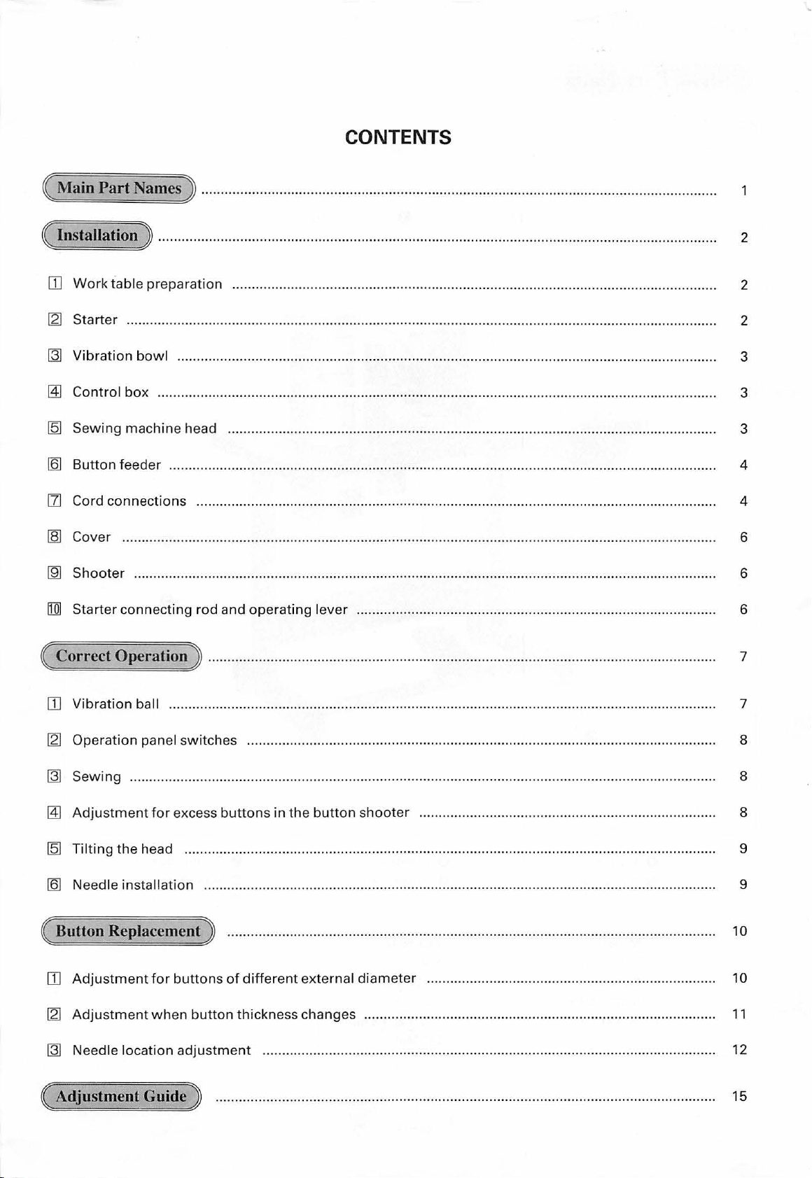
CONTENTS
....................................................
..............
.............
.....
................................ .
( Installation ) .
OJ
Work
table
[2)
Starter ...
~
Vibration
~
Control
[Q]
Sewing
[Q]
Button
CZl
Cord
~
Cover .......................................
~
Shooter
[Q]
Starter
feeder ....
connections
connecting
..
. . . . . .
..
prep
arat
.......................................................
bowl .....................
box ....
machine
............................
head ..............................................................................
....... ....... ...........
........................................................... .......................................................................... 4
.......... .....................................................
rod
. . . .. .. . . . .
.. . ...
. . .. .
..
. . . . . . . . . .
...
. ...
... . ..
. . . . .. . .
..
. .
.. . ..
. .
...
. .
..
. . ... . . . .
..
. . . . . . .
..
. .
.. ... . .
...
. .
... . ... . .. . ...
ion ...................................................................................................................
......
.....
..... ..
and
...........................................
......
..........
......
...................................
...
..........
................................................................................................
............................................... .........
.........
........
..........................................................................................
....
................. ......................... ........................................ 6
operating
lever ...........
..........
....
............
....................... .........................
....
...... .....
...
....
....
..... ....... ....
..........................................
................................ 2
.......................
...... ....... .....
............. 6
. . ... . .
..
. . 2
......... 2
...
......... 3
..
......... 3
....
....
..
...... 6
3
4
( Correct Operation) .
OJ
Vibration
[2)
Operation
~
Sewing ....
~
Adjustment
[Q]
Tilting
[Q]
Need le installation
ball ...........................
panel
switches .... ........ ...............
.....
....
.....
....
for
excess
the head ............................................. ............................
................................................
( Button Replacement)
OJ
Adjustment
[2)
Adjustment
~
Nee
dle location
for
buttons of
when
button thickness changes
adjustment
..
. . . . .
..
. .
..
. . .
..
. . . . .
....
.....
.........
................... ................
buttons
.....
in
the
..
. . .
..
. . ........
different
..
. .
..
. . .
..
. . ...
....
..
. . . . . . . .
..
. .
..
...
.. .....
..
. . .
..
..
. . .
..
. .
..
. ..
...
. .. .
..
. .
..
. .. . . . .
.. . .. . ...
. . . ... .
....
.................................................................................................... 7
.......... .......... ...... .......... ................................ ......................... 8
....
..............................................................................
butt
on
..
.. ... . . . . . . . . . . . ..
exte rnal di
shooter ...
ameter
..................................
......
...........................................
................................
..........
............................... .......................................... 9
...
. .
..
. . .
...
. . . .
..
. .
..
. . .
..
. . . . .
..
. .
..
. . .
..
. .
..
.....
.......................................................................... 10
......................................................
...... ............
............................... 9
...
. .
...
. . . . ..
..
..
. ..
....
... . ...
...
..
..
. . 1 o
..
11
12
7
8
8
( Adjustment Guide)
....
............
...
............
....
.........
...............
...
...... ...............
......
..........
..........
.....
........... .
..
15
Page 3
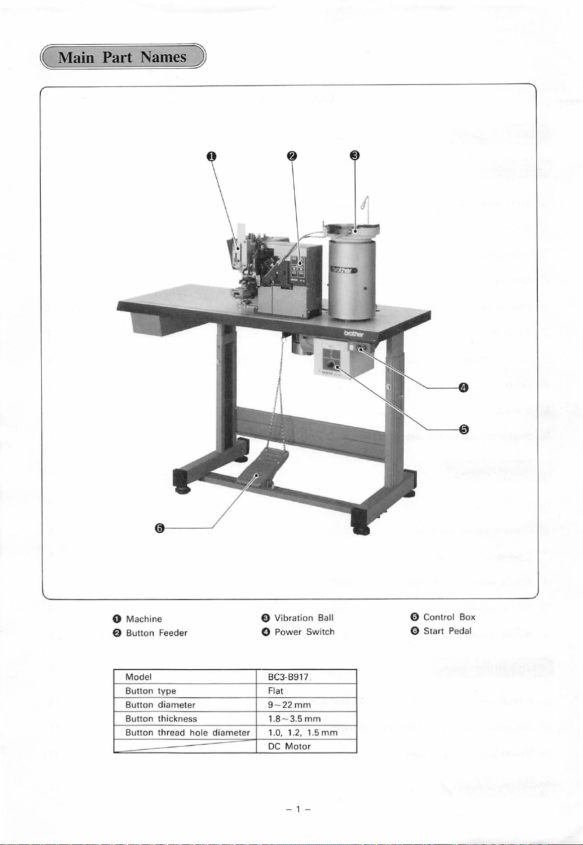
( Main Part Names )
0
Machine
6
Button
Model
Button
Button di
Button thickness
Button
Feeder
type
ameter
thr
ead
hole
diameter
Vibration
0
Power
BC3-B917
Flat
22
9-
1.8 - 3.5
1.0, 1.2, 1.5
DC
Motor
- 1 -
Ball
Switch
mm
mm
mm
E)
0
Contro
l Box
0 Start Pedal
Page 4
Cautions on Use
The
sewing
Be sure
to
machine
turn
the
power
( Installation )
OJ
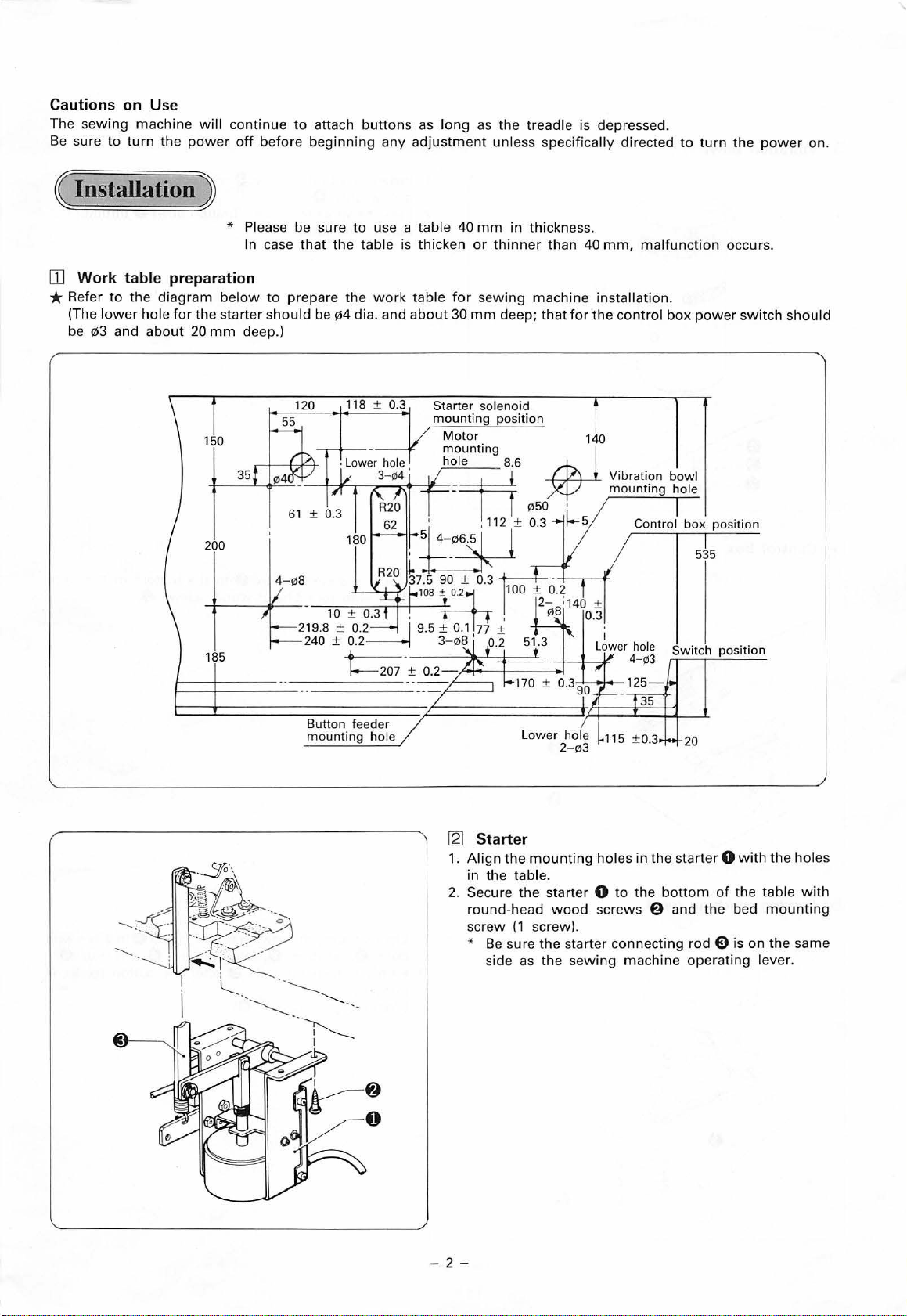
Work table preparation
* Re
fer
to
the
diagram
low
er
and
hole for
about
20
(The
be
!1l3
will continu e
off befo
* Plea
In case
below
to
the
starter
should
mm
deep
150
35
to
attach
re
beginning any
se
be sure
that
prepare
be
.)
61 ± 0.3
buttons
to
use a table 40
the
table is thicken
the
work
!1l4
dia
. and
118
± 0.3
as
long
adjustment
or
table
for sewing
about
30
mm
as
the
treadle is depressed.
unless specifically directed
mm
in
thickn
ess.
thinner
deep; that
than 40
machine installation
for
mm,
the
control
to
turn
malfunction
.
box
power swit
the
power
occurs.
ch
on.
should
200
185
4- 08
Button feeder
mounting
hole
[2] Starter
1.
Align
the
in the table.
2.
Secure
round-head
screw
the
(1
* Be sure
s
ide
as
mounting
starter 0 to the
screw).
the start
the
holes
wood
screws @ and the bed
er
connecting
sewing
535
20
in
the starter 0 with
bottom
rod
machine opera
position
of
the
0 is on
ting
the
holes
table
with
mounting
the same
lever.
-2-
Page 5
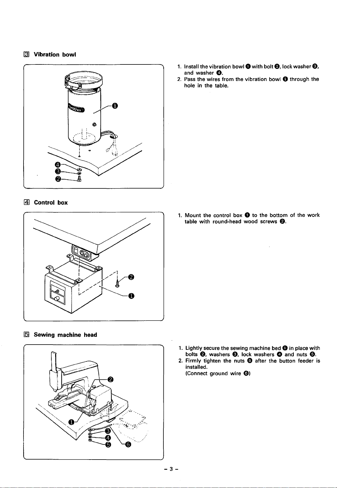
[31
Vibration
~
Control box
bowl
1.
Install the vibration
and washer
2.
Pass
the wires from the vibration bowl 0 through the
hole in the table.
1.
Mount
table
the control box 0
with
round-head
e.
bowiO
wood
with
bolt
to
the bottom
screws
e,
lock washer E),
of
the
e.
work
[5]
Sewing machine head
1.
Lightly secure the sewing machine bed 0 in place
bolts
e.
washers
2.
Firmly tighten the nuts 0 after the button feeder
installed.
(Connect ground wire
-3-
e.
lock washers e and nuts
0)
with
0.
is
Page 6
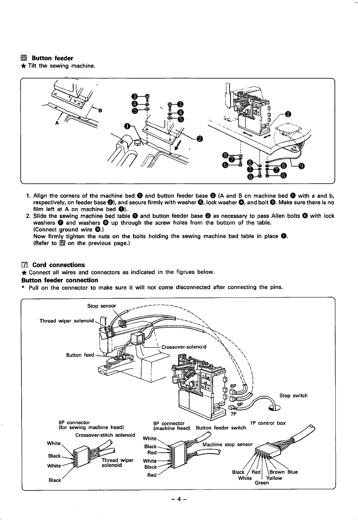
161
Button feeder
*Tilt
the sewing machine.
1.
Align the corners
respectively, on feeder base
film left at A on machine bed
2.
Slide the sewing machine bed table 8 and button feeder base 8
washers 0 and washers 0 up through the screw holes from the bottom
(Connect ground wire E).)
Now firrrily tighten the nuts on the bolts holding the sewing machine bed table in place
(Refer to
151
of
the machine bed 8 and button feeder base 8 (A and B on machine bed 8 with a and
f)),
and secure firmly with washer
8).
on the previous page.)
0,
lock washer
as
0,
necessary
of
and bolt
the table.
8.
Make sure there is no
to
pass Allen bolts 0 with lock
8.
b,
[1] Cord connections
* Connect all wires and connectors
Button feeder connection
* Pull on the connector to make sure
Thread wiper solenoid
Button feed
6P
connector
(for sewing machine head)
Crossover-stitch
solenoid
as
indicated in the figrues below.
it
will not come disconnected after connecting the pins.
9P
connector
(machine head) Button feeder switch
White
7P
Black~
Red,
White
Black.---·~
~
Red
control box
-4-
Page 7

Control box connection
* Connect
the
ground
wire
from
the vibration bowl
to
the motor.
9P
connector
2P
connector
3P
connector (female)
Black
White
Power switch connection
White
Black
Green
Power switch connector
(control box)
Control box
Green--"'"""''
Black--~IL.
White--""""''
....
Red----ftO\'
White
Brown
Red
~;;;;;;
-5-
Page 8

IB1
Cover
~
Shooter
* Attach the button feeder cover 8
f)
with
screw
e,
lock washer
*
Be
sure
to
pass the wires through the hole in the cover
when attaching the button feeder cover
1.
Raise the shooter lock pin 8 on the vibration bowl
and secure the shooter e
through the notch in the shooter.
2.
Secure the shooter 8
feeder
0.
with
to
the button feeder
e,
and washer
by
inserting the pin e
thumb
screw 8 on button
8.
0.
8,
H]J
Starter connecting rod and operating lever
1.
Tilt the sewing machine.
2.
Mount
3.
Mount
4.
Pass
with washer
·* After this installation refer
the spring peg 8 on the bottom
the operating lever spring 8 on the peg.
the starter connecting rod pin 8 through the starter connecting rod 0 and operating lever
0 and snap ring
to
8.
page
of
the sewing machine bed table.
22
and readjust the starter solenoid.
* As shown in the figure above, the hole in the starter connecting rod 8 are not located in the center
Mount
the rod
with
the
wider
hole-to-edge gap towards the operating lever spring
-6-
f).
0,
and secure the pin
of
the
rod.
Page 9

( Correct Operation )
ill
Vibration ball
(1)
Switch
Switch
(2)
Turn
(3)
The amount
increase
decrease
ON
ON
the
adjustment
when
when the
the
pow
er
switc
the switch 0
knob
of
vibration
the
knob
knob is
for
is
turned
h.
@.
of
turned
the con
the
vibration ba
to
the r
to
tro
the
l box.
ight,
and
left.
ll w ill
will
Adjustment of
btother
the
vibration ball
BA-1
0
*The vibrating
If the
buttons
(1) Loosen
plate B 0 and the
(
2)
Loosen
plate C 9 and the v
Make sure any st
(3) L
oosen and
pla
te
(4) L
oose
oose
(5) L
is
approximately 0.7
(6) Loosen scr
mm
2
When
(7)
at the e
* The
bowl
are
not
and
adjust
and
adjust
adjust
A 0
and
n a
nd
adjust
n a
nd adju
ew
0 . and
so that
buttons jam
vibrating
ntran
the button
ce.
arranges the face
fed
properly, adjust
set
screw@
vibrat
set
screw 0 so
ibrating
anding
set
screw 0 so that
the vi
brating
bolt 0 so that the
st
screw
mm.
adjust
at
the
bow
l s
hould
so
ing
bow
bow
buttons
bowl.
~
so
that the
the
s will be fed sm
entra nce
be a
of the
that
two
l.
that
one
l.
are
turned
one
button
gap
gap
between
to
the shooter,
djust
ed each
buttons
as
in
the same
follows
buttons
button can pass
button
between
oothly
.
can pass
dow
n, and
can pass thr
faces are ali
the
the button
to the
loosen
time
-
7-
direction,
through
through the
that
the
buttons flow
ough
gned
when
bottom
thumb
the
of
the hei
and button width
shoo
ter.
scr
ew
button
s are changed .
and
the
gap
gap between
the
gap
the
sorting
ght
'f)
and turn
feeds the
bet
ween
smoothly.
between
pla
control
contro
l plate
so
plate 0
that
buttons
the
bottom
the
bottom of
the bot
te
0 is
G)
the
to
of alignment
tom
of
slid
and
the
to
appro
buttons
the
shooter.
alignment
ali
gnment
in and out.
button
xima
tely
do
not
jam
top
Page 10

[21
Operation panel
[3)
Sewing
switches
'---------'L----1
...;r-+-ii--·
1.
Button feeder switch
*
Be
sure
to
set the switch 0
2.
Trouble indicator
(1)
When buttons are being fed
the trouble indicator
(2)
When the trouble indicator
are not supplied
If the emergency stop indicator on the operation panel
is blinking, press EMERGENCY
indicator off.
3.
Manual switch
* Operates as the button-feeding switch.
6).
to
the button clamp.
* Only operable when the
"head"
4.
Crossover-stitch switch 8
*
Can
crossover stitch
* When
twice
*
If
once.
and the stop lamp is
be used
"crossover" is selected, sewing is started only
for
selection
for
4-hole buttons.
"no
crossover" is selected, sewing is started
for
one button.
to
to
f)
will
be
f)
is flashing, buttons
STOP
mode
not
of
crossover stitch
ON.
the button clamp,
OFF.
·to turn the
switch is set
flashing.
or
to
no
~
Adjustment
for
excess
buttons
in
the
button
*Turn
shooter
(1)
(2)
(3)
the power switch on.
clamp, the button
will
If
a button is in the button
be sewn on
wlien
the start pedal
0 is pressed.
Buttons
held depressed. Release the pedal
To feed a button
bowl and button feeder switch on.
Turn the button carrier 0 by hand in the direction
the arrow, and remove any button(s)
to remove any excess buttons
point
Press the manual switch to feed a button
clamp. Press the pedal
will
continue
to
be attached
if
the pedal 0 is
0.
to
the button clamp, turn the vibrating
from
the button
carrier pin
With the button carrier 0 in this position, pull lever
A. ·
e.
from
to
begin sewing.
the shooter at
to
the button
of
6)
-8-
Page 11

151
Tilting the head
* Before making this adjustment, be sure to switch
161
Needle installation
OFF
the power switch and stop the
(1)
Remove bed base cover R 8 and remove the V-belt f.).
For installation and removal
easily removed
more
machine side is being manually turned.
(2) Remove the arm bed holding belt 0 and
machine
downward.
while
motor
of
the V-belt f.), it can be
the pulley e at the
pulley.
tilt
the
(1) With the long groove
front, insert the
set screw
Use TO x 1
needle all the way in and secure
e.
of
the needle 8 facing
to
the
with
-9-
Page 12

( Button Replacement )
III Adjustment for buttons
1.
Bed
slide adju
stment
0 '
(1)
Adjust
the
width of
smooth
The bed sl
Adjust so that the clearance
(2) There are
installed.
To
Adjust
(3)
scr
attach
the
ew
0 and ad
ly.
ide
two diff
butto
button gui
tab
ns
the s
le
eren t
from
ju
st
of
different external diameter
lide
table
assembly
between
button
15 to
22
de
sha
ft
button
assembly
f)
can be adjusted
upper
mm
in
and the plate
stopper s
f)
the
buttons 0 and the edge
covers 0 . The
diam
eter, loosen scr
cam
haft 0 so
by
using the slide table
for
butt
on di
cove
r for standard button sizes
ew
0 a
so
that
the
button
that
button
screw
ame
ters
of
the slide table
nd
replace
s are se
stopper
E)
so
that
of
9 to
22
assembly
cover 0 (non
nt along one
sha
ft 0 intervenes
the
buttons
mm.
of 9 to
standard accessories).
by
one
0 pass a
f)
is 0.5 - 1.0
17
mm
. Loosen
between
is initially
the thum
buttons.
long
mm.
b
2.
Button
(1) Loosen step
(2)
(3)
(4
) Firm ly
clamp
adj ustment
Lightly
Close the
tighten step scr
tighten
screw
button
step
0 and insert a
ew
0 . and
clamp
screw
f)
opening 0.5 to 1.0
0 .
button
remove
into the
the
button.
mm
button
using
clamp
the plate
0.5 mm- 1.0
f)
.
E)
.
mm
- 1
0-
Page 13

3.
Shooter replacement
(1)
Lift the shooter lock pin
(2)
Remove
Adjust
the table below.
thumb
for
button diameter and thickness as shown in
screw
0,
and remove the shooter
8,
and replace the shooter
e.
e.
121
Adjustment
Thickness
when
button
thickness changes
Shooter
Mart
A
~-
B
c
D
E
F
G
H
J
K
L
M
N
p
(1)
Check to be sure that buttons 0 are being
sent
(2)
Adjust the bed slide height so the buttons 0 slide
smoothly.
Install accessory spacers
thickness.
(3)
Check
grasped
~b
a
15mm
17mm
25mm
13mm
13mm
15mm
15mm
17mm
18mm
20mm
20mm
21
mm
22mm
25mm
to
the shooter
to
be sure that buttons are being securely
by
the button clamp.
b
2.7mm
3.5mm
4.0mm
2.5mm
3.0mm
3.2mm
3.8mm
4.0mm
4.5mm
3.5mm
4.0mm
4.5mm
5.7mm
4.7mm
e.
* The standard gap is
Button
~
Diameter
9-12mm
11-14mm
12-16mm
16-22
mm
9-12rnm
11-14mm
11-14mm
12-16mm
12-17mm
14-18mm
14-18mm
15-19
mm
15-19
mm
16-22
mm
Replace the shooter.
as
required
for
buttons 1.8 to 2.2
Thickness
1.9-2.3mm
2.5-3.1
2.8-3.6mm
1.8-2.1
2.1-2.6mm
2.2-2.8mm
2.7-3.4mm
2.8-3.6mm
3.2-4.1
2.5-3.1
2.8-3.6mm
3.2-4.1
4.0-5.3mm
3.3-4.3mm
smoothly
by
the button
mm
Thickness
mm
mm
mm
mm
mm
thick.
0
* When using the button catch plate 4
--,a
r-
®.-0b
-
~
A
B
c
D
E
F
G
H
J
a: hole gap
3.3mm
3.8mm
2.6mm
2.8mm
3.0mm
3.2mm
3.4mm
3.6mm
3.8mm
0b:
1.2mm
1.2mm
1.0mm
1.2mm
1.2mm
1.2mm
1.2mm
1.2mm
1.2mm
hole
I
I
Spacers
B~tton
thrckness
mm
in height, attach the washer (No. 506029-001
h
!
II
I
h: height
3 c
3 D
4
4
4
4
4
4
4
~
A
B
E
F
G
H
J
K
L
-
11
-
thickness
1.8--
2.2
2.2-
2.6
2.6-
3.0
3.0-
3.4
@_0b
a: hole gap
2.7mm
3.1
mm
2.4mm
2.2mm
2.4mm
2.6mm
2.8mm
3.0mm
3.2mm
3.4mm
3.6mm
mm
mm
mm
mm
as
----
----
----
No
0
0b:
1.2mm
1.2mm
1.2mm
1.0mm
1.0mm
1.2mm
1.2mm
1.2mm
1.2mm
1.5mm
1.5mm
0.4mm
0
-------
---
---
).
A
hole
Accessory
0.8
mm
1.2
mm
----
---- ----
0
----
0
----
----
l h
h: height
3
3
3
4
4
4
4
4
4
4
4
Page 14

~
Needle location adjustment
* The a
1. Horizontal feed
Button hole gap
(1) Insert a
(2) Disengage the
(3)
(4) T
djustment
Make s
If
the needle a
w
ill
urn the
If the
ure the needle is
ent
hor
0 .
Af
ter adju s
* If the p
is required whenever the
posi
tion
button
er
izonta l feed
into
clut
nd
the
center
pulley
to ali
ting
the
ull
ey is turned
not
the
ch, a
nd
butt
on h
of
butt
gn the needle with
position
button
bent.
button
ole cannot
clamp 0 so
clamp
turn
the pull
on
hole A.
is
not
properly ad
by
hand, be sure
but
ton carri
er
is replaced
0 .
ey
to align the needle
be aligned, l
the needle enters the center
oosen
bolt
6 , and s
button hole
justed, loosen horizont
to
turn
B.
the pull
ey
(button
with button
hift the
al
of
button
thro
ugh the
hole
gap
hole
A.
button
feed adjustment nut 0 and
holes A
clamp
and
end
of the stitch.
is chagned).
0 so
th
B, firmly ti
at the needle
adj
ust scale
ghten
bolt
6 .
2.
Vertical feed
*
Whe
n sew
*
When sewing
horizontal feed
(1) After adjusting the
(
2) Adju
(3) L
oosen
(4) T
urn
" Check that the ne edle enters the center of b
position
ing
buttons
buttons
st vertical feed
bolt
the
pulley
Adj
ust the horizontal feed for
Adjust
the
lever
6 ,
vertica
with
two
hol
es,
set the vertical feed
with
four
he~les,
set the vertical feed
scal
e.
Butt
on
hole
gap
hor
izontal feed positio
adjustment
and shift
to
the butt
check that the needle enters the cen ter of
l feed f
lever 0 to the vertical feed scale
on clamp 0 so
or
button holes
button
n, co
holes
ntinue
turn
that
the
utt
on holes A, B, C, and
A
~
B a
A
~
C.
- 12 -
adjustmen
adjustment lever
ing the
t l
pulley
ever 0 to
to
0.
needle will
nd
C •
enter
button holes C and D.
D.
0 to the
ali
gn
the need le
the
cent
D.
@.
er
but
of
button
ton hole
with butt
holes A and
gap
on
on
hole
the
C.
C.
Page 15

3.
If button hole arrangements differ
<-->
4.
Adjustment
of
the button receiver
fOCJ\
\f25J)
4 mm
Q
Washer
506029-001
®
(1) Loosen the screw 0 and exchange the button carrier
plate
G).
CAOSSOVER
snTO£S
@@@
48,
Four holes
ON
switch
or
position.
ON
right.
Two
holes
(1)
Check whether
(2)
While pressing and holding the manual switch
(3)
While continuing
* Assist the button clamp
(4)
Adjust so that the needle tip and the button receiving pin ~ coincide.
Loosen
bolt ~ and adjust the entire button feeder left
or
not
the feeder switch
to
hold the manual switch
by
lifting up.
G)
is at the
48,
move the arm 0
the
power
for
button movement until
switch.
it
grasps a button.
-
13-
Page 16

5.
Button
* Please use
clamp
and
button
following
carrier
3 types
adjustment
of
button
clamp
depending
on
the
slape
of
button.
A
B
c
Button application
U Button
0 Button face is a curved shape.
hollow
is larger and flat.
D
D
0
Button
clamp
Part No.
505356-000
Part No.
506569-000
Part No. [Standard)
506570-000
()
Button
!Installation)
(1) Remove the
(2)
Remove and change the
(3)
Move
the
button
(4)
Move
the
button
(5) Remove the gauge 0
"
(6)
Attach the
Repeat
(4)
button
hollow
button
and check again.
is a conical shape.
clamp
carrier
carrier plate e so
clamp
O.
button
shutter
from
fit
carrier plate
0 in the direction
that
the shaft 0 is in the gauge
the
for
button
the
carrier plate
button
e.
(Tighten the screw E)
of
the arrow, and set the gauge 0 in the
0.
e.
and
tighten
type.
the
temporarily.)
screw
E).
button
carrier plate
e.
-
14-
Page 17

Adjustment guide
Refer to this guide when different buttons are used
utt
When b
diameter
changes
on
(D) thickness (t) t
8J
o
Wh
en
changes
button
===}
When
hole
changes
button
gap (B)
Page
Vibrating
~
Butt
on Slide Base
B
utton
Catch Plate
~
ju
st
Ad
bottom
Ad
just bu
ust bed
Adj
Adj
ust the st
Replace
cove
r
butt
on top/
selecto r
tto
n gui
Ad
slide w
the
de
just butt
Replace
opper
butto
n t
adjust
on
th
e shooter coil
idth
op
-------------
Adjust height control
plate
ment dial
Adjust ri
and
button
ons
positi
butto
ght/left
carrier
n
needle
pin
2
2
2
2
6
5
5
5
6
8
8
Machine Head
5
7
- 15 -
 Loading...