

Page 1
SERVICE
FOR
MANUAL
BAS
-4
11
BAS -415
SINGLE HEAD ELECT RONIC EMBROIDERY
MACHINE
I
· ·.~
-
Page 2
(
PART
NAMES )
CONTENTS
·.
· · · · · · · · · · · · · · · · · · · · · · · · · · · · · · · · · · · · · · · · · · · · · · · · · · · · · · · · · · · · · · · · · · · · · · · 1
( MECHANICAL
[I] .upper
00
Lower
00
Thread
[j]
Thread
[§] Needle
[§] Picker mechanism • . . . . . . . . . . . . . . . . . . . . . . . . . . . • . • • . . . . . . . • . . . . . . . • . • . . • • . • . . . . . . • . . . . . . 8
[1]
Drive, (X)
[I]
Drive, (Y)
( STANDARD ADJUSTMENT ) · · · · · · · · · · · · · · · · · · · · ·
[I]
Adjusting
~
Adjusting
00
Adjusting
[j]
Adjusting
[§]
Adjusting
DESCRIPTIONS ) · · · · · · · · · · · · · · · · · · · · · · · · · · · · · · · · · · · · · · · · · · · · · · · · · · · · · · 3
shaft
mechanism . . . . . • . . . . . . . . . . . . . . . . . • • . . . . . . . . • . . . . . . . . . . • . . • • . . • . . . . . . . . . . . . 3
shaft
and
rotary
trimmer
wiper
bar
feed
feed
mechanism . • . . . . . . . . . . • . . . . . . . . . . . . . . . . . . . . . . . . . . . . . . . . • . . . . . . • • • • • • . • 5
mechanism . • . . • . . . . . . . . . . . . . . • . • . . . . . . . . . . . . . . . . . . . • • • • • . • • . • . . . . . . . • . . . 6
flip-up
mechanism . . . . . . . . . . . . . . . . . . . . . . . . . . . . . . . . • • • . . . . • . . . • . . . . . . . . . . . . . . . • . 9
mechanism . . . . . . . . . . . . . . . . . . . . • . • . . . . . . . . . . . . . . . . • . • . . • . . . . . . . . . . . . • • . 10
needle
timing
cloth
presser
knife
and
picker . . . . . . . . . . . . . . . . . . . . . . . • . . . . . . . . . . . . . . . . . . . • . . . . . . . . . . . . . . . . . . . • • • • . . 15
hook
mechanism . . . . . . • • • • • . . . . . . . . . . . . . . . • . . . • • . . • • . . . . . . . • . . . . 4
mechanism . . • • . . . . . . . . . . . . . . . . . . . . . . . . . . . . . . . . . . . . • . . . . . . . . . . • • • . • • . 7
·.
· · · · · · · · · · · · · · · · · · · · · · · · · · · · · · · · · · ·
bar
height
of
needle and
height
fixed
...•..............••......
rotary
hook
. . . . . . . . . . . . . . . . . . . . . . . . . . . . . . . . . . . . • . • . . . . . . . . . . . . . . . . • . 13
knife
. • . . . . . . . . . . . . . • • . . . . . . . . . . . . . . . . . • . . . . . . . . . . . . . . . . . . . . . 14
. . • . . . • • . . . . . . . . . . . . . . . . . . . . . . . . . . . . • . • • • • . • 13
~
. . . . . . . . . • • . . . . . . . . • . . • • • • • • • • •
11
11
[§]
Adjusting
[1]
Adjusting
00
Adjusting
00
Adjusting
lim
BAS-411·415
In]
Adjusting
1m
Adjusting
lj}
Positioning
IB1
How
1. X-feed
2. Y -feed
the
thread
wire
wire
wire
thread
bobbin
test
synchronizer . . . . . . . • . • . . . . . . . . . . . . . . . . . . . . . . . . . . . . . . . . . . . . . . . . . . . . . . . • . . . . . 23
home
over
to
adjust
thread
wiper
tension
. . . . . . . . . . . . . . . . . . . . . . . . . . . . . • . . . . . . . . . . • . . . . . . • . . . . . . . . . . . . . • . • • • • • . 17
. . . . . . . . . . . . . . • . . . . . . . . • . . . . . . . . . . . . . . . . . . . . . . . . . . . . • . . . . . . . . . . . • . . . . 18
breakage
winder
mode
position
limit
sensor
sensor (thread breakage detector) . . . . . . . . . . . . . . . . . . . . . . . . . . • . . . . . . 35
. . . . . . . . . . . . . . . . . . . . . . . . . . . . . . • . . . . . . . . • . . . . . . . . . • . . . . . . . • • 16
.....•.................•........................••...•.•...••••
detect
...................•.........................................
. . . . . . . . . . . . . . . . . . . . . . . . . . . . . . . . . . . . . . . . . . . • • • • • • . . . . • . . . . . . . . .
using
stud
..........................•.•.....•.•............
home
position
...................................•..••..•...............
plate
. . . . . . . . . . . . . . . . • . . . • . . . . . . . . . • . . . . . . 26
17
19
20
21
28
( LUBRICATION ) · · · · · · · · · · · · · · · · · · · · · · · · · · · · · · · · · · · · · · · · · · · · · · · · · · · · · · · · · · · · · · · · · · · · · · · 36
[I]
~
Machine
Feed
head . . . . . . . . . . . . . . . . . . . . . . . . • . . . • . . . . . . . . . . . . . . . . . . . . . . • • • • • . . • . . . . . . . . . . . . 36
guide
mechanism
.......................................•........•..............
38
Page 3
(
REPLACINGANDADJUSTINGPARTS)
[I]
Removing and
~
Removing and
lm
Removing needle
1!1
Replacing
~
Replacing
[§]
Attaching X wire
[1]
Attaching Y wire
(
ELECTRIC
[!)
Circuit
~
Replacing
00
Fuses
(!]
P-ROMS
~
DIP switches . . . . . . . . . . . . . . . . . . . . . . . . . . . . . . . . . . . . . . . . . . . . . . . . . . . . . . . . . . . . . . . . . . . . . . . . . 62
[§]
Connectors . . . . . . . . . . . . . . . . . . . . . . . . . . . . . . . . . . . . . . . . . . . . . . . . . . . . . . . . . . . . . . . . . . . . . . . . . . 67
board
...............................................................................
up
and
jump
adjusting
adjusting
bar
down
solenoid
machine head (1) . . . . . . . . . . . . . . . . . . . . . . . . . . . . . . . . . . . . . . . . . . . . . 39
machine head (2) .
case
............................................................
motion
.....................................................................
.....................................................................
parts . . . . . . . . . . . . . . . . . . . . . . . . . . . . . . . . . . . . . . . . . . . . . . . . . . 42
..............................................................
COMPONENTS ) · · · · · · · · · · · · · · · · · · · · · · · · · · · · · · · · · · · · · · · · · · · · · · · · · · · · · · · · · 46
locations
circuit
. . . . . . . . . . . . . . . . . . . . . . . . . . . . . . . . . . . . . . . . . . . . . . . . . . . . . . . . . . . . . . . . . . . . . . . . . . . . . 60
board
...•............................................................
...............................................................
· · · ·
..
··
. . . . .
· · · · · · · · · · · · ·
.. . ..
..
. . . . . . .
··
· · · ·
..
··
· · · · · · · ·
. . . . .
.. ..
··
..
.. .. ..
· · · · · · ·
. . . . 40
··
39
41
43
44
45
46
47
58
[1]
troubleshooting
BAS-411
BAS-415
00
Harness connections and connectors
(
EXPLANATIONOFOPTIONALPARTSINSTALLATION)
[]]
ML
6511amp set . . . . . . . . . . . . . . . . . . . . . . . . . . . . . . . . . . . . . . . . . . . . . . . . . . . . . . . . . . . . . . . . . . . 106
~
Light
marker
00
Connecting
1!1
Bobbin
(
TROUBLESHOOTING)·····························································
winder
[!) Mechanical
~ Electrical
00
List
BAS-411 . . . . . . . . . . . . . . . . . . . . . . . . . . . . . . . . . . . . . . . . . . . . . . . . . . . . . . . . . . . . . . . . . . . . . . . . 122
of
problem
error
flowchart
..........................................................................
..........................................................................
. . . . . . . . . . . . . . . . . . . . . . . . . . . . . . . . . . . . . . . . . . . . . . . . . . . . . . . . . . . . . . . . . . . . . . 107
optional
problem
messages . . . . . . . . . . . . . . . . . . . . . . . . . . . . . . . . . . . . . . . . . . . . . . . . . . . . . . . . . . . . . . . 122
parts
. . . . . . . . . . . . . . . . . . . . . . . . . . . . . . . . . . . . . . . . . . . . . . . . . . . . . . . . . . . . . . . . . . . . . 116
. . . . . . . . . . . . . . . . . . . . . . . . . . . . . . . . . . . . . . . . . . . . . . . . . . . . . . . . . . . . . . . . . . 120
...........................................................
number
with
machine . . . . . .
. . . . . . . . . . . . . . . . . . . . . . . . . . . . . . . . . . . . . . . . . . . . . . . . . . . . . . . . . . . . . . . 118
...........................................
..
..
. . . . . . . . . . . . .
70
70
81
92
· · · · · · · · · · · · · · · · · · · · · · · · · · · 106
.. ..
. . . .
..
. .
..
. . . . .
..
. 112
118
BAS-415 . . . . . . . . . . . . . . . . . . . . . . . . . . . . . . . . . . . . . . . . . . . . . . . . . . . . . . . . . . . . . . . . . . . . . . . . 125
BAS-411 KEYBOARD
BAS-415 KEYBOARD UNIT CONTROL
BAS-411 CONTROL
BAS-41
5 CONTROL
UN
IT CONTROL
BLOCK
BLOCK
DIAGRAM
DIAGRAM
BLOCK
BLOCK
DIAGRAM
DIAGRAM
.........................................................
.........................................................
Page 4
(
Part
(
BAS-411
names
)
)
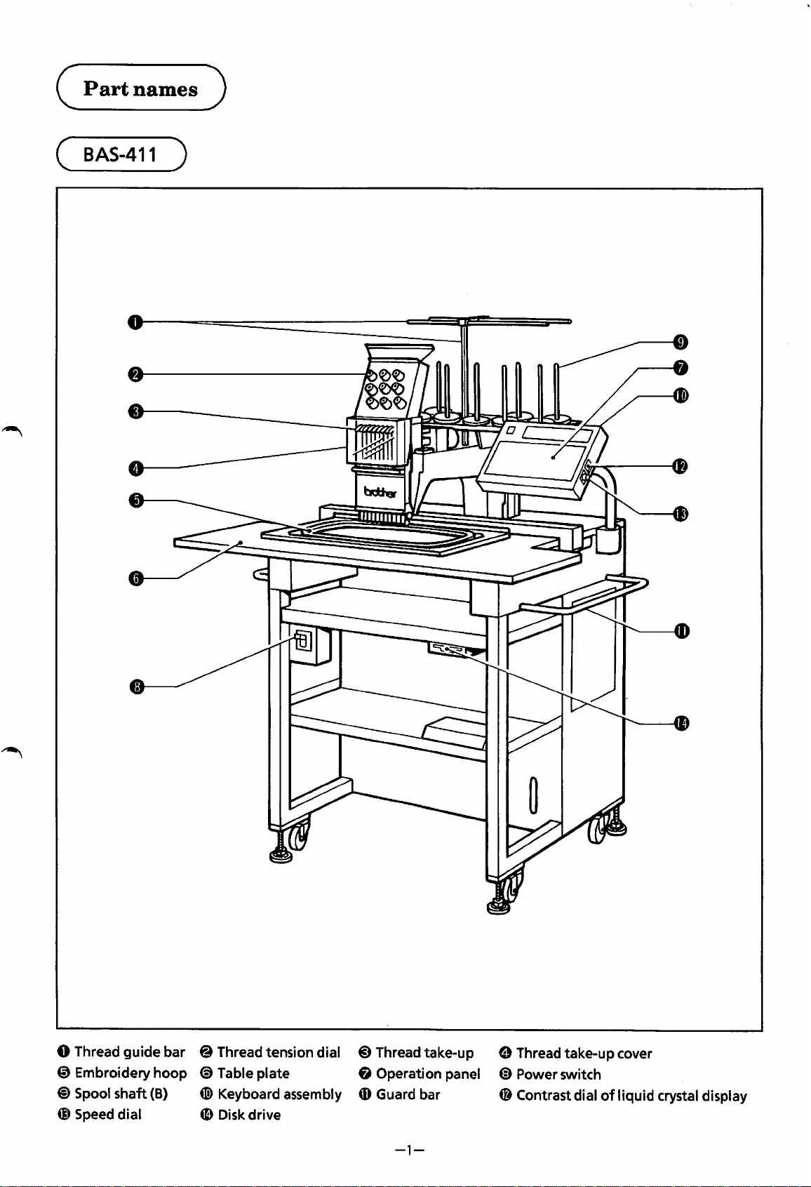
0 Thread
0 Embroidery
@)Spool
@ Speed dial
guide
shaft
bar
hoop
(B)
@ Thread tension dial
<9
Table plate 6 Operation panel
(!) Keyboard assembly
4D
Disk drive
@)
Thread take-up
CD
Guard bar
-1-
0 Thread take-up cover
@)
48
Power switch
Contrast dial
of
liquid
crystal display
Page 5
( ·
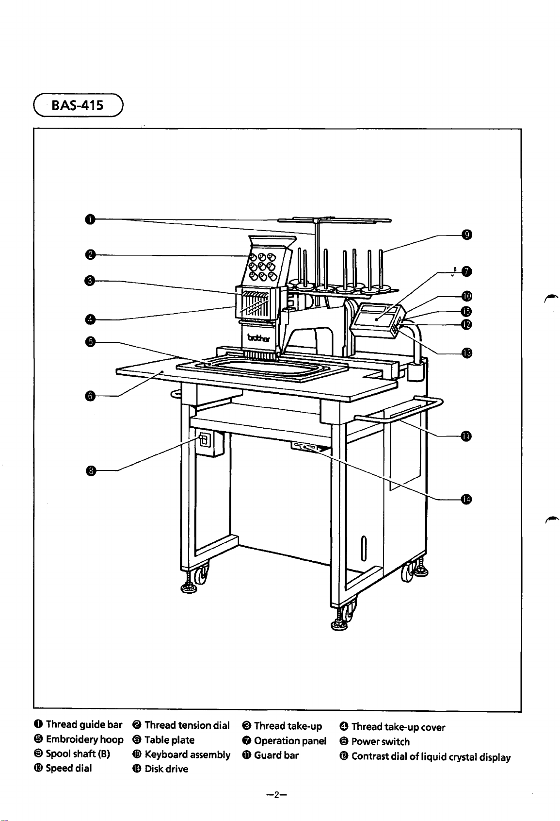
BAS-415
)
0 Thread
@ Embroidery
@)
Spool
Q) Speed dial
guide
shaft
bar 8 Thread tension dial
hoop
(B)
(!) Table
tD)
4D
plate
Keyboard assembly
Disk drive
@)
Thread take-up
8 Operation panel
4D
Guard bar
8 Thread take-up cover
~
C8
-2-
Power switch
Contrast dial
of
liquid
crystal display
Page 6
(MECHANICAL
DESCRIPTIONS )
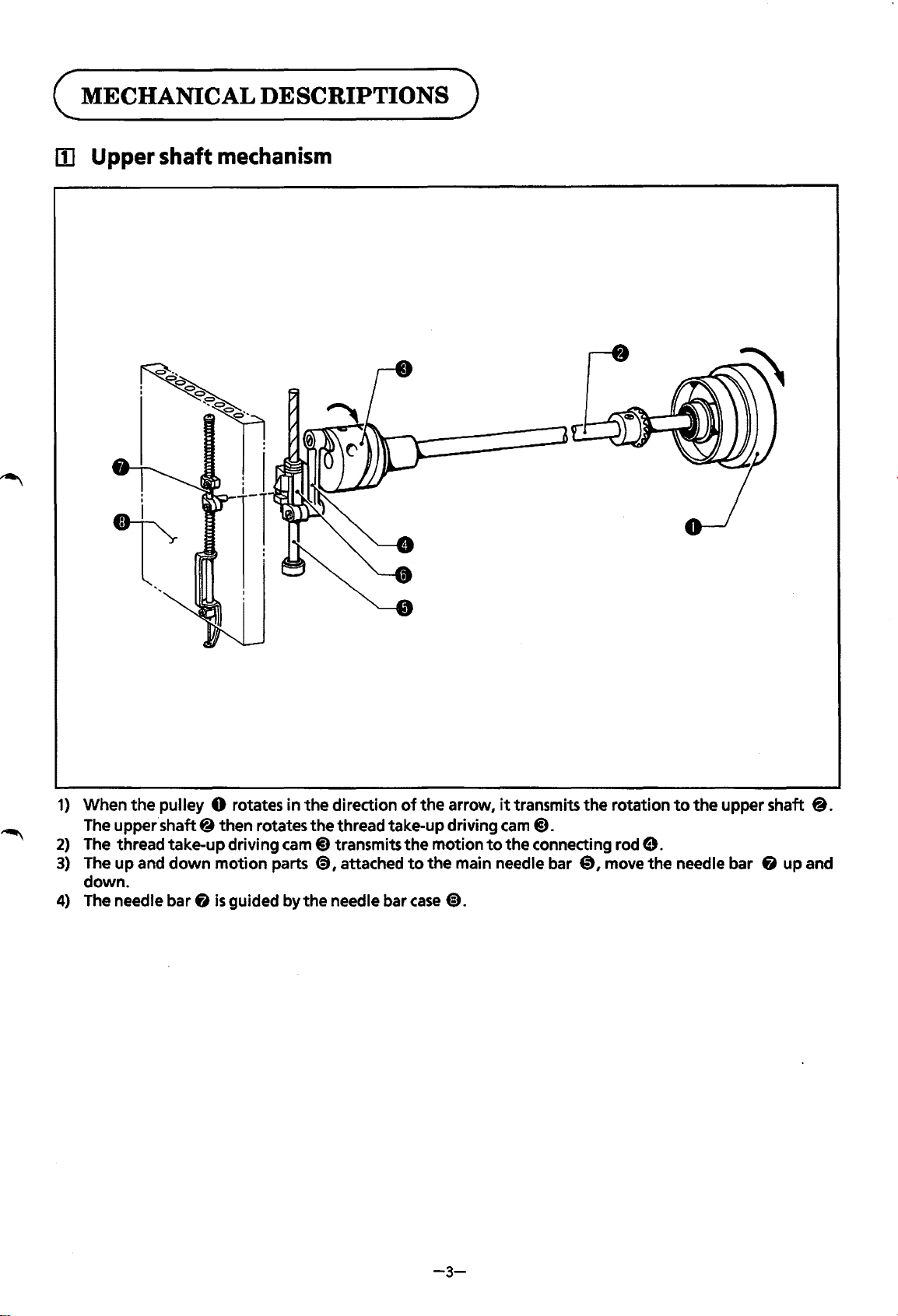
lii Upper shaft
mechanism
1)
When
the
pulley 0 rotates
The upper.shaft 8 then rotates
2)
The thread take-up driving
3)
The
up
and
down
motion
down.
4)
The needle bar 8
is
guided by
in
cam@)
parts
the
direction
the
thread take-up driving
transmits
<9,
attached
the
needle bar
of
the
to
case
the
arrow,
motion
the
@).
it
cam
to
the
main needle bar
transmits
@).
connecting rod
the
0,
rotation
9.
move
the
to
the
upper shaft
needle bar 8 up and
8.
-3-
Page 7
~
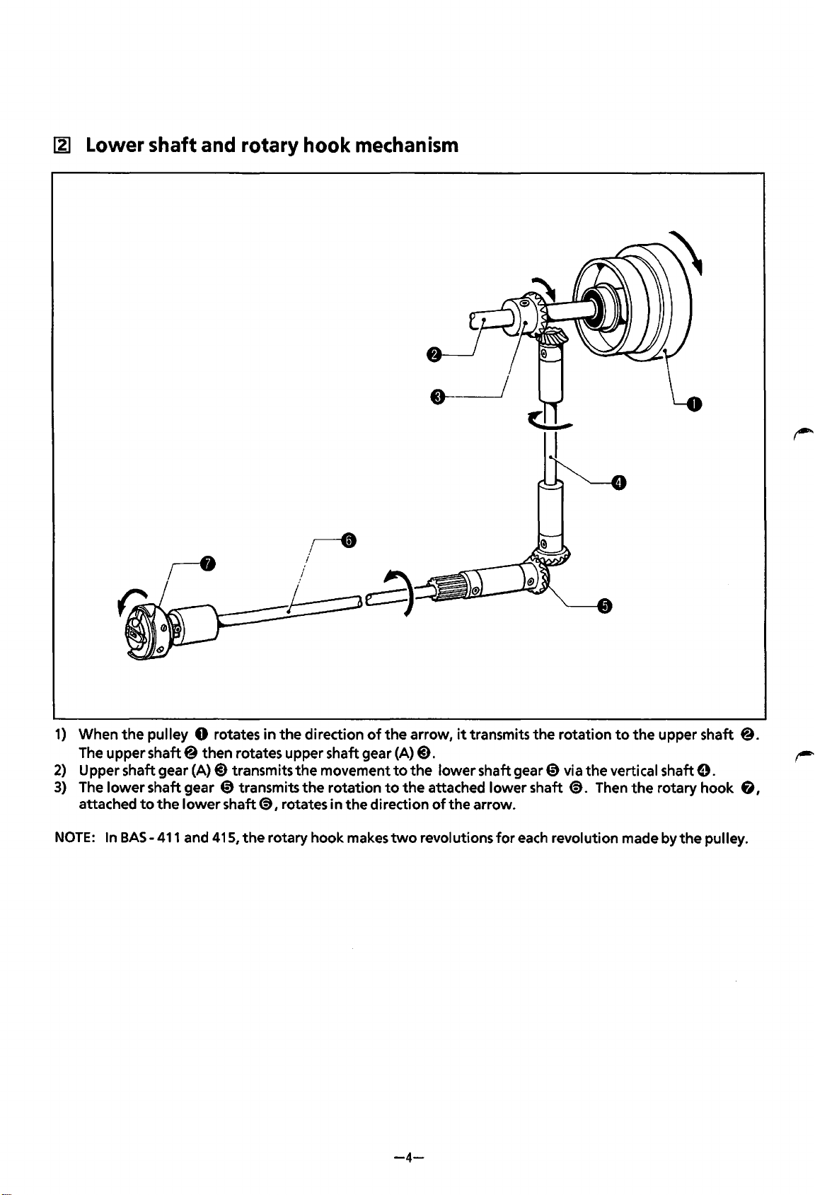
Lower shaft and rotary hook mechanism
1)
When
the
The upper
2)
Upper shaft gear
3)
The
lower
attached
NOTE:
In BAS-
pulley 0 rotates
shaft@
shaft gear 0 transmits
to
the
411
then rotates upper shaft gear (A)@).
(A)@)
lower
and 415,
in
transmits
shaft@), rotates in
the
rotary hook makes
the
direction
the
the
of
the
movement
rotation
the
direction
to
to
the
two
arrow,
the
it
transmits
lower
shaft gear 0 via the vertical shaft
attached lower shaft
of
the arrow.
revolutions
the
rotation
@).
for
each revolution made by
to
Then
the
upper shaft @.
the
rotary hook
the
e.
6,
pulley.
-4-
Page 8
~
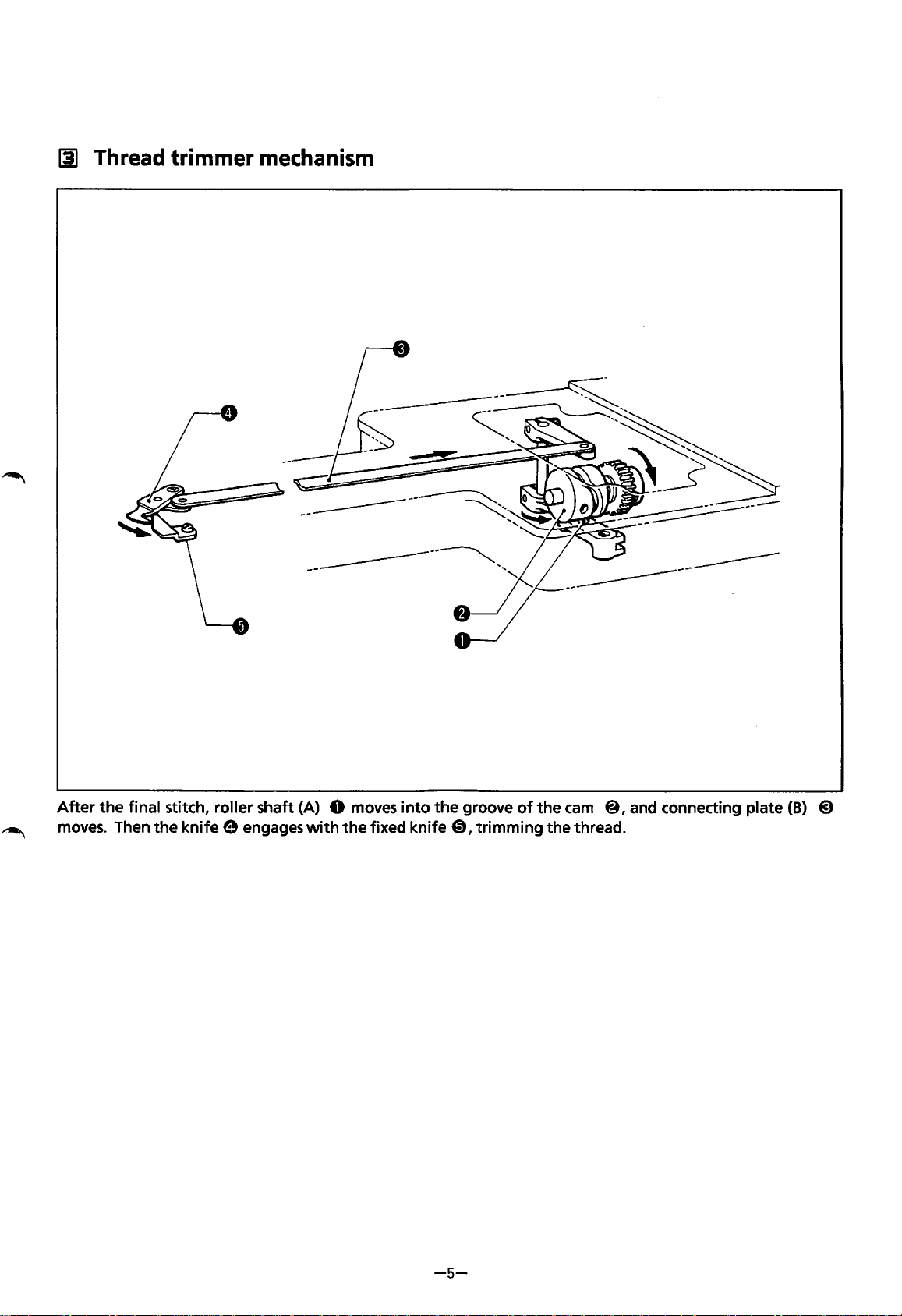
Thread trimmer
mechanism
-------------------
~
After
moves.
the
final stitch, roller shaft (A) 0
Then the knife 0 engages
moves
with
the fixed knife
into
the
groove
0,
of
trimming the thread.
the
cam
@,and connecting plate
(B)
@)
-5-
Page 9
II]
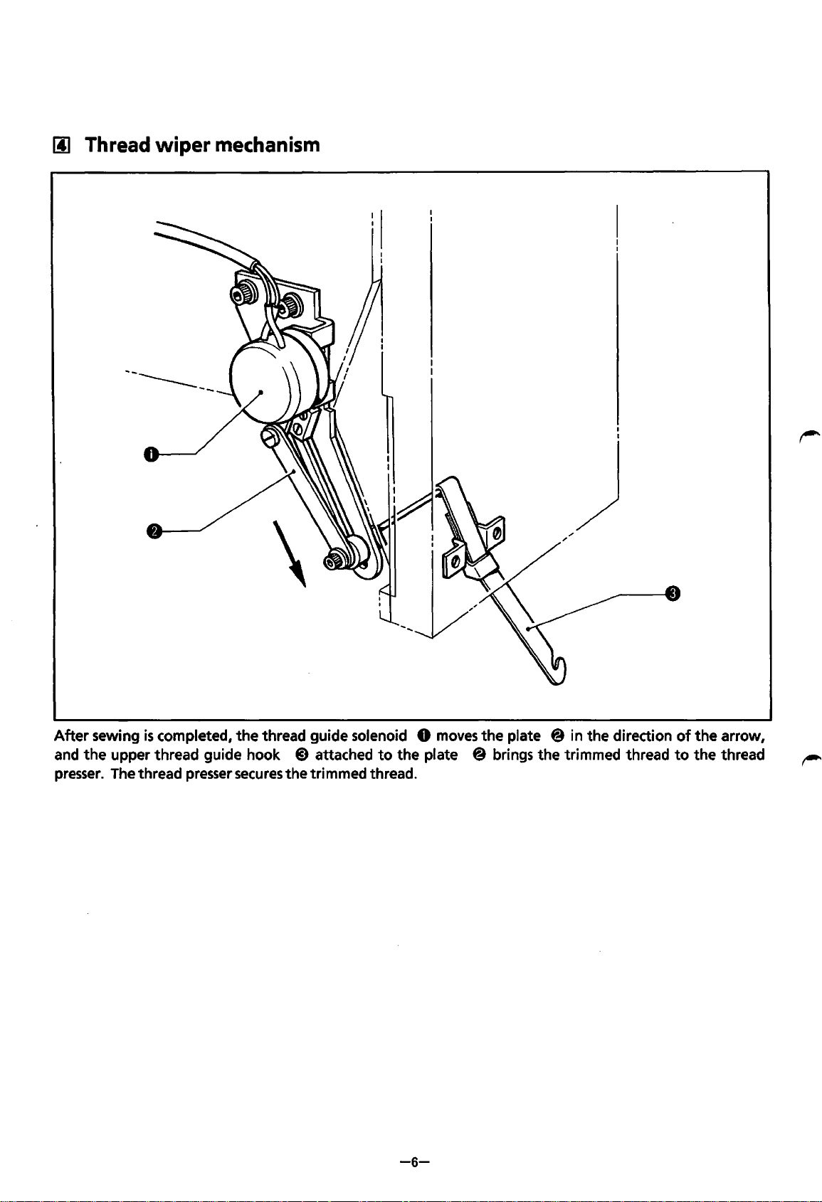
Thread
wiper
mechanism
~--------
After
sewing
and
the
presser.
is
completed,
upper thread guide hook
The thread presser
the
thread guide solenoid 0
secures
@)
attached
the trimmed thread.
to
the plate @ brings the trimmed thread
moves
the
plate
@in
the direction
of
to
the
the
arrow,
thread
-6-
Page 10
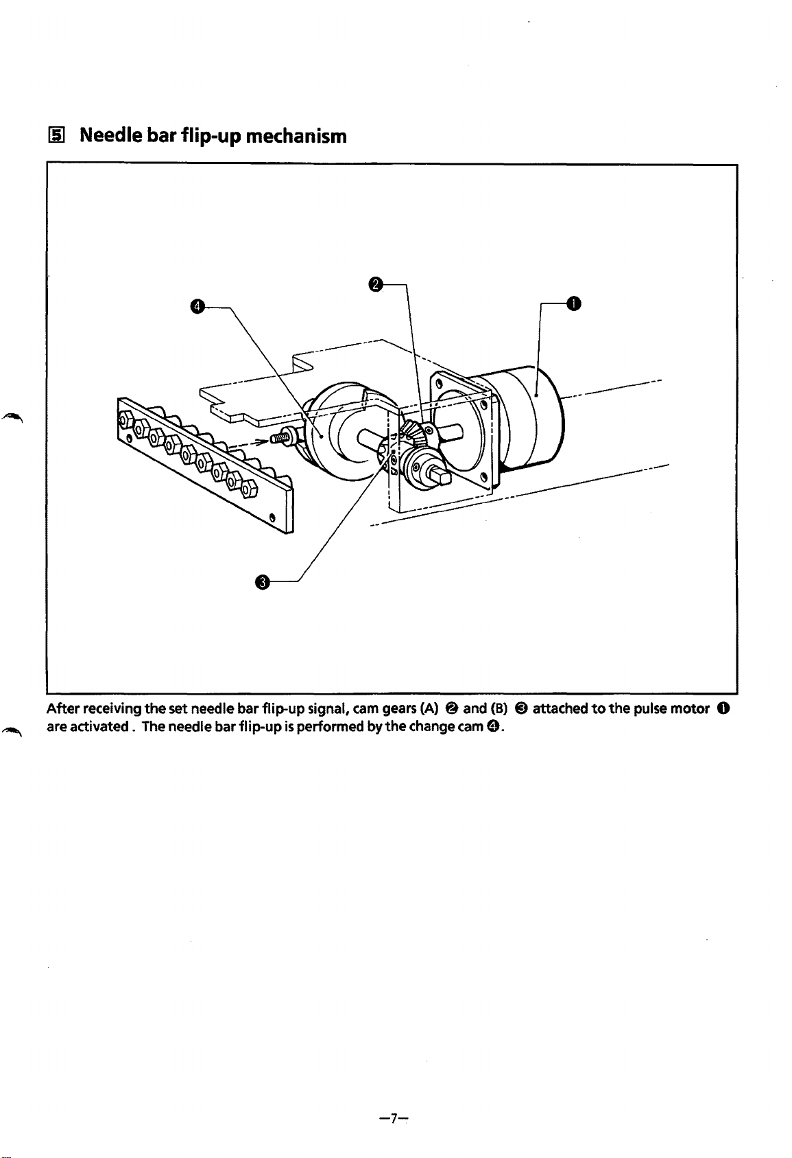
[§]
Needle
bar
flip-up
mechanism
~~------
After
are
activated.
receiving
the
set needle bar
The needle bar
flip-up
flip-up
signal,
is
performed
cam
gears (A) 8 and
by
the
change cam
(B)
9.
@)
attached
to
the
pulse
motor
0
-7-
Page 11
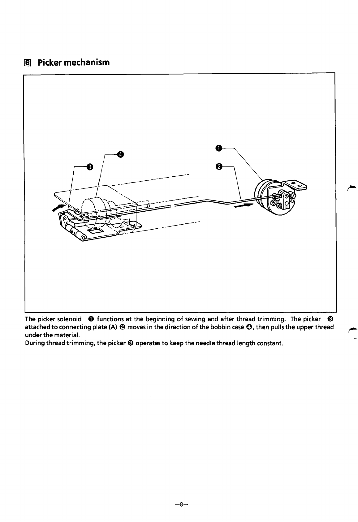
[§]
Picker
mechanism
------------
The
picker solenoid 0 functions
attached
under
During thread trimming,
to
connecting plate
the
material.
at
the
(A)@
the
picker@) operates
moves in the direction
beginning
to
keep the needle thread length constant.
of
sewing and after thread trimming.
of
the bobbin
case
e, then pulls the upper thread
The
picker
@)
-8-
Page 12
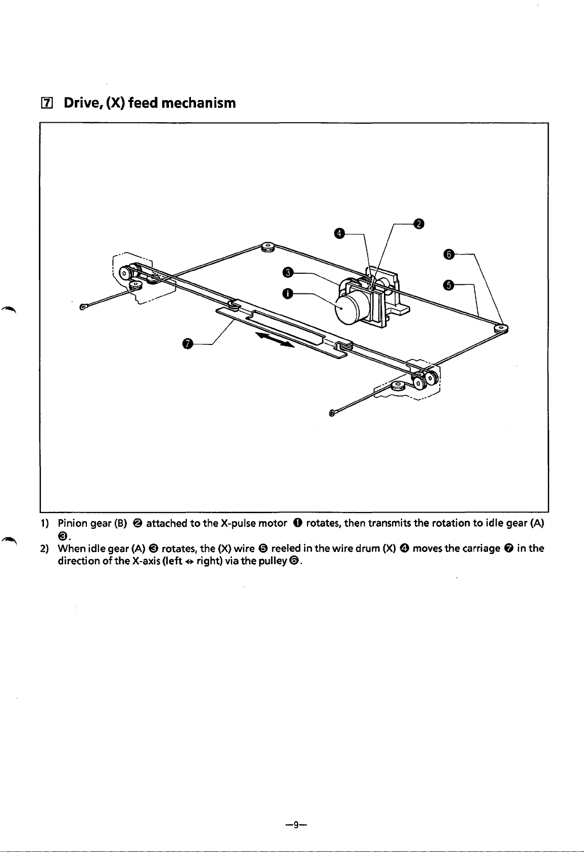
[1]
Drive, (X) feed mechanism
1)
Pinion gear
@).
2)
When idle gear (A)@) rotates, the (X) wire
direction
of
(B)
@ attached
the
X-axis
(left
e right) via
to
the X-pulse motor 0 rotates, then transmits the rotation
the
CD
reeled in the wire drum
pulley
<9.
(X)
e moves
to
the
carriage & in
idle gear (A)
the
-9-
Page 13

[II.
Drive, (Y) feed
mechanism
1)
Pinion gear (B)@
2) When idle gear (A) @)rotates, the
right
and the
pulley8.
of
theY-pulse motor 0 rotates, then transmits the rotation
left
move the carriage
(Y)
wires @)(left) and (right) reeled in
fi
in the direction
of
theY-axis (backwards e forwards) via the
to
idle gear
the
wire drums
(A)@).
(Y)
8 on
the
-10-
Page 14
c
STANDARD
lii
Adjusting
ADJUSTMENT
needle
bar
height
)
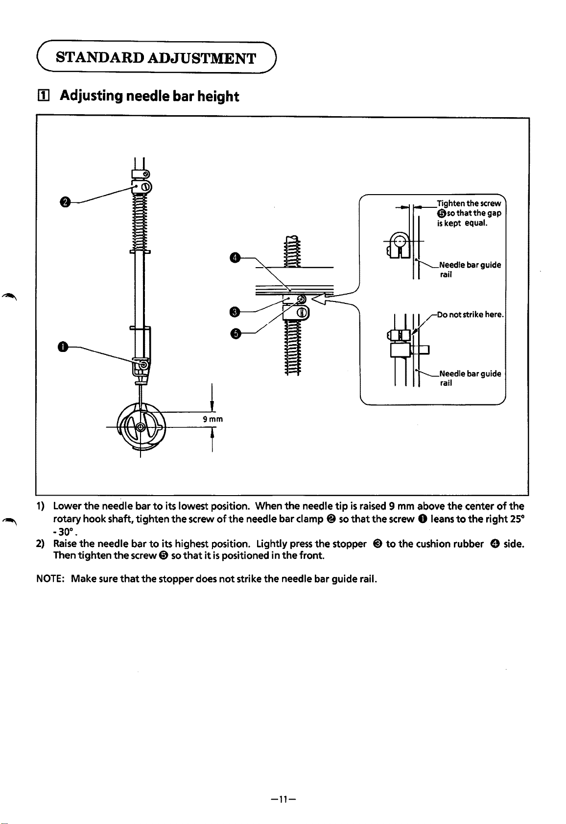
Tighten the screw
0so
that
the
is
kept equal.
gap
~
1)
Lower
rotary hook shaft,
the
-30°.
2)
Raise
the
Then
tighten
NOTE:
Make sure
needle bar
tighten
needle bar
the
screw 0
that
the
to
its lowest position. When
the
screw
of
the
needle bar clamp @
to
its highest position. Lightly
so
that
it
is
positioned in
stopper does
not
strike
the
needle
press
the
stopper
the
front.
the
needle bar guide rail.
tip
is
raised 9 mm above
so
that
the
screw 0 leans
@)
to
the
center
to
the
the
cushion rubber 9 side.
of
right
the
25°
-11-
Page 15
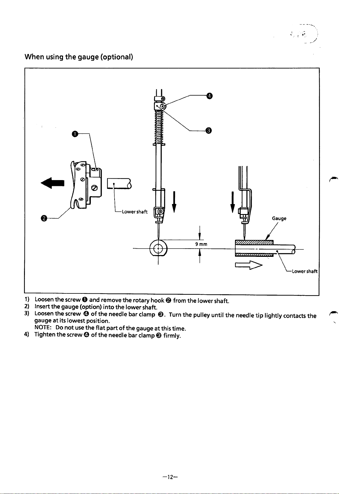
When using
the
gauge (optional)
Gauge
1)
Loosen
2)
Insert the gauge (option)
3)
Loosen
gauge
NOTE:
4)
Tighten
the screw 0 and remove
the
screw e
at
its lowest position.
Do
not
use
the
screw 9
of
the
of
the
into
the lower shaft.
the
needle bar clamp
flat
part
of
the
the
needle bar
rotary
gauge
clamp@)
hook@
@).
Turn
at
this time.
firmly.
from the lower shaft.
the
pulley until the needle
tip
lightly contacts
the
-12-
Page 16
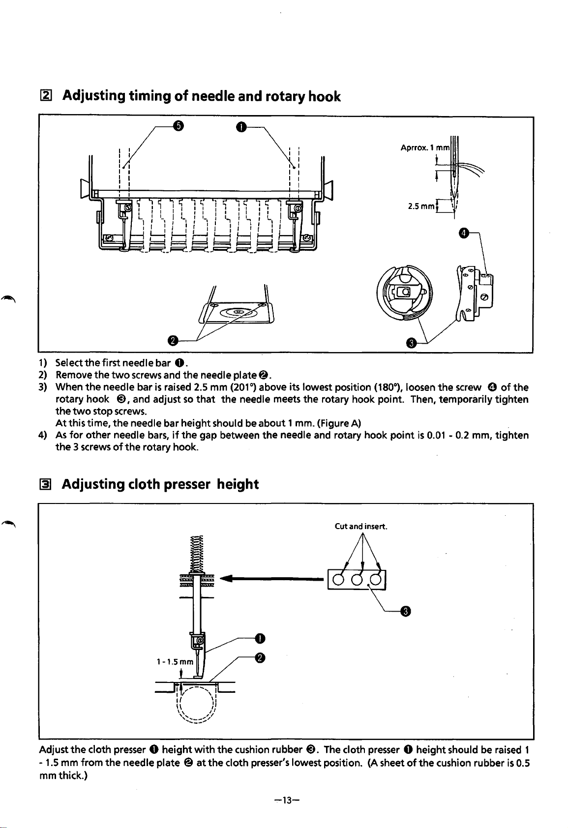
~ Adjusting timing
of
needle and rotary hook
I I
1/
I
I
I
I I
I I
: I
1)
Selectthefirstneedlebar
2)
Remove
3)
When
rotary hook
the
At
4)
As
the
the
two
the
needle bar
@),
two
stop screws.
this time,
for
3 screws
the
other needle bars,
of
the
I
I
\
I I
I I
I I
I
I
Aprrox.1 mm
2.5mm
0.
screws and
and adjust
needle bar height should be about 1 mm. {Figure A) .
rotary hook.
is
raised
the
needle plate@.
2.5
mm
so
that
if
the
gap between
(201°)
the
needle meets
above its lowest position (180°), loosen
the
rotary hook point. Then, temporarily
the
needle and rotary hook
point
is
0.01 -0.2
the
screw 0
mm,
of
tighten
tighten
the
~
Adjusting cloth presser height
Adjust
mmthick.)
1.5
the
cloth presser 0
mm
from
the
needle plate @
height
with
at
the
Cut and insert.
the
cushion rubber
cloth presser's lowest position. {A sheet
@).
The cloth presser 0 height should be raised 1
of
the
cushion rubber
is
0.5
~13-
Page 17
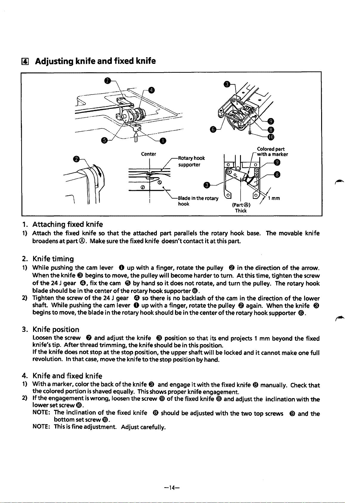
(j] Adjusting knife
1.
Attaching fixed knife
1)
Attach
broadens
the
fixed knife
at
part®.
Make sure
and
fixed knife
so
that
the
the
attached part parallels
fixed knife doesn't contact
the
rotary hook
it
at
this part.
base.
~-
The movable knife
2.
Knife timing
1)
While pushing
When
the
of
the
24 J gear e I
blade should be in
2)
Tighten
shaft. While pushing
begins
3.
Knife position
Loosen
knife's tip.
If
the
revolution. In
4.
Knife and fixed knife
1)
With
the
2)
If
the
lower
NOTE:
NOTE:
the
to
the
knife does
a marker, color
colored portion
engagement
set screw
The inclination
bottom set screw
This
the
knife
@)
screw
move,
screw & and adjust
After
that
CD).
is
fine adjustment. Adjust carefully.
cam
lever 0 up
begins
the
of
the
thread trimming,
not
case,
is
to
move,
fix
the
cam
center
the
the
blade in
stop
the
is
shaved equally.
wrong, loosen
of
24 J gear e
cam
lever 0 up
the
at
the
move
the
back
of
of
the
fixed knife @)should
CD).
with
a finger, rotate
the
pulley
CD
by hand
the rotary hook supporter@).
rotary hook should be in
the
knife
the
knife should be in this position.
stop position,
knife
the
knife
This
the
will
become harder
so
it
does
so
there
is
no backlash
with
a finger, rotate
@)
position
the
upper shaft
to
the
stop position by hand.
@)
and engage
shows proper knife engagement.
screw
@)
of
the
the
not
rotate, and
the
so
that
it
fixed knife
be
adjusted
pulley @ in
to
turn.
of
the
cam
the
pulley @again. When
center
with
of
the
its end projects 1 mm beyond
will
be locked and
the fixed knife
@)
and adjust
with
the
direction
At
this time, tighten
turn
the
pulley.
in
the
direction
rotary hook supporter
it
cannot make one
@)
manually.
the
the
two
top
of
the
The
rotary hook
of
the
Check
inclination
screws
@)
the
the
knife
@).
the
with
and
arrow.
screw
lower
@)
fixed
full
that
the
the
-14-
Page 18
1§1
Adjusting
picker
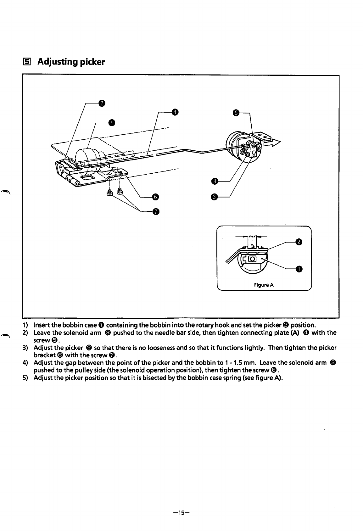
1)
Insert
2)
Leave
screw0.
3)
Adjust
bracket(!)
4)
Adjust
pushed
5)
Adjust
the
bobbin
the
solenoid arm
the
picker @
with
the
gap between
to
the
pulley side (the solenoid operation position), then tighten
the
picker position
case
the
so
screw
0 containing
@)
pushed
that
there
is
8.
the
point
of
so
that
it
the
bobbin
to
the
needle bar side, then
no
looseness and
the
picker and
is
bisected by
into
the
the
rotary hook and set
tighten
so
that
it
functions lightly. Then
the
bobbin
bobbin
to 1 -1.5
case
spring
Figure A
the
picker@ position.
connecting plate (A) e
tighten
mm.
Leave
the
solenoid arm
the
screw@).
(see
figure A).
with
the
the
picker
@)
-15-
Page 19
[§]
Adjusting
the
thread wiper
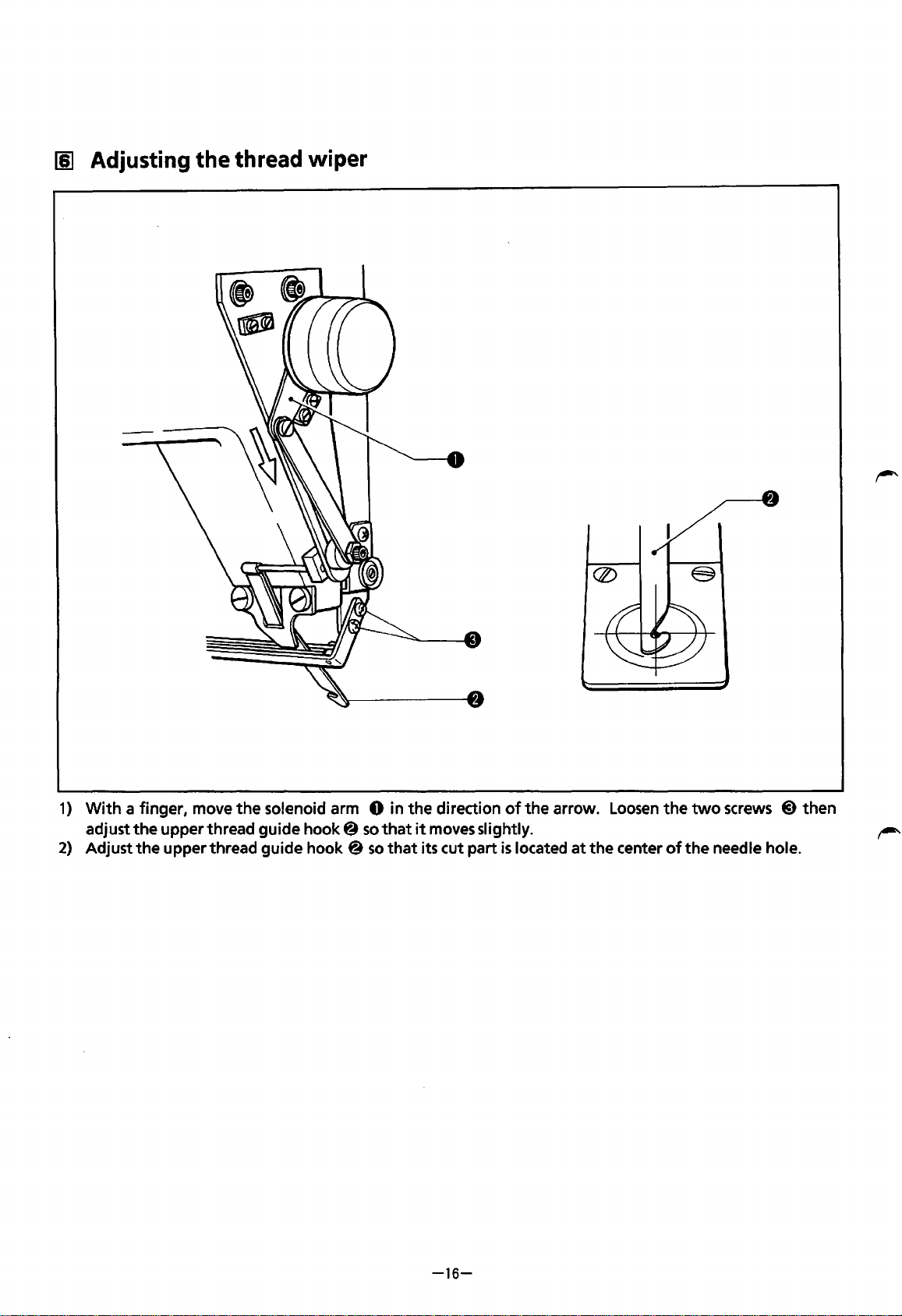
1)
2)
With
a finger, move
adjust
the
Adjust
the
the
solenoid arm 0 in
upper thread guide
upper thread guide hook @
hook@
so
so
the
that
that
direction
it
moves slightly.
its cut part
of
the
is
located
arrow.
at
the
Loosen
center
the
of
two
screws @ then
the
needle hole.
-16-
Page 20
111
Adjusting
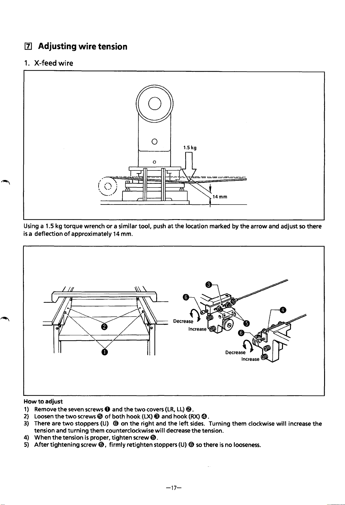
1.
X-feed wire
wire
tension
Using a 1.5 kg
is
a deflection
torque
of
wrench
approximately
or
a similar
14
mm.
tool,
0
push
at
1.5 kg
the
location marked by
the
arrow
and adjust
so
there
How
to
adjust
1)
Remove
2)
Loosen
3)
There are
tension and
4) When
5)
After
the
seven screws 0 and
the
two
two
stoppers (U)
turning
the
tension
tightening
the
screws 0
is
screw
of
both
(S)
on
them counterclockwise
proper,
0,
tighten
firmly
two
covers
hook
(LX)
the
right
screw
retighten stoppers
@)
and hook
and
will
0.
(LR,
the
decrease
-17-
LL)@.
(RX)
left
(U)
(S)
0.
sides.
the
so
Turning them clockwise
tension.
there
is
no
looseness.
will
increase
the
Page 21
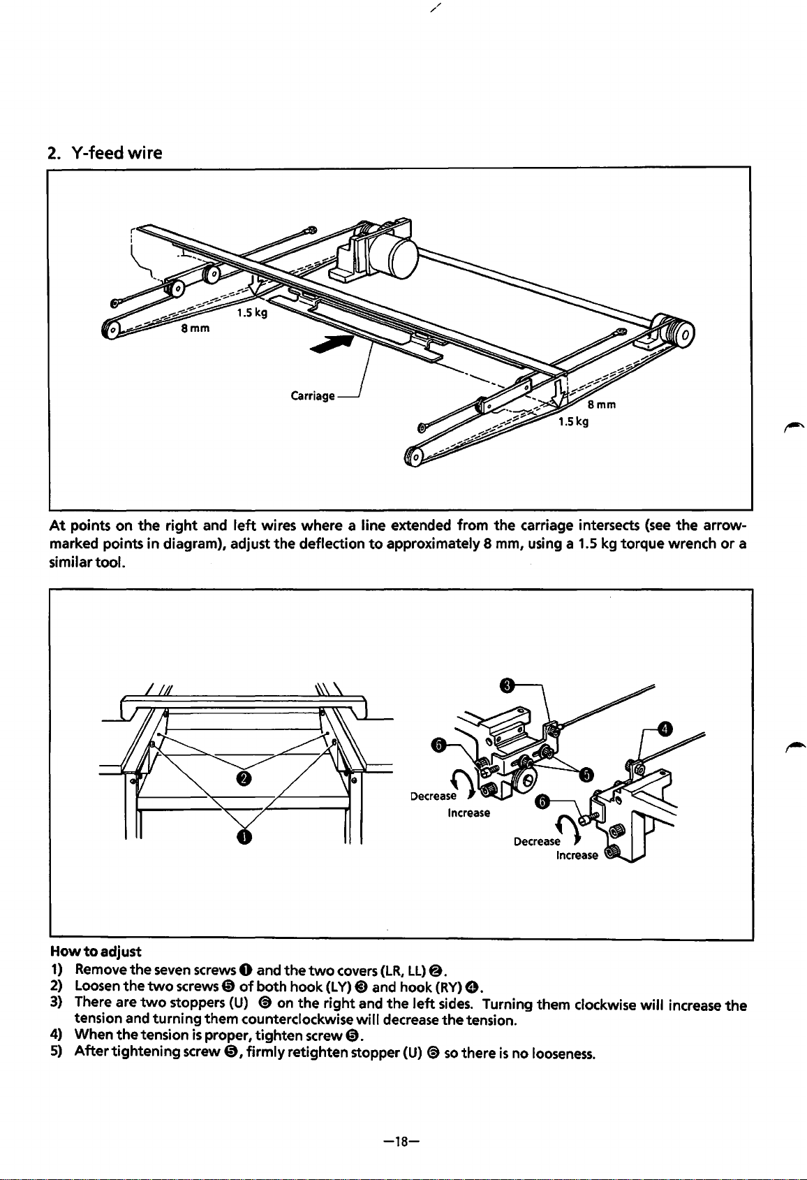
2.
Y-feed wire
At
points
marked points
similar
on
tool.
the
right
and
in
diagram), adjust
left
wires where a line extended from
the
deflection
to
approximately 8
the
carriage intersects
mm,
using a 1.5 kg torque wrench
(see
the
arrow-
or
a
How
to
adjust
1)
Remove
2)
Loosen
3)
There are
tension and
4)
When
5)
After
the
seven
the
two
two
stoppers
turning
the
tension
tightening
screws 0 and
screws
CD
of
(U)
them counterclockwise
is
proper,
screw@,
the
both hook
(S)
on
tighten
firmly
retighten stopper
two
covers
(L
Y)
the
right
screw@.
(LR,
@)
and hook
and
the
will
decrease
-18-
LL)
left
(U)
@.
(RY)
(S)
8.
sides.
the
tension.
so
there
Turning them clockwise
is
no
looseness.
will
increase
the
Page 22
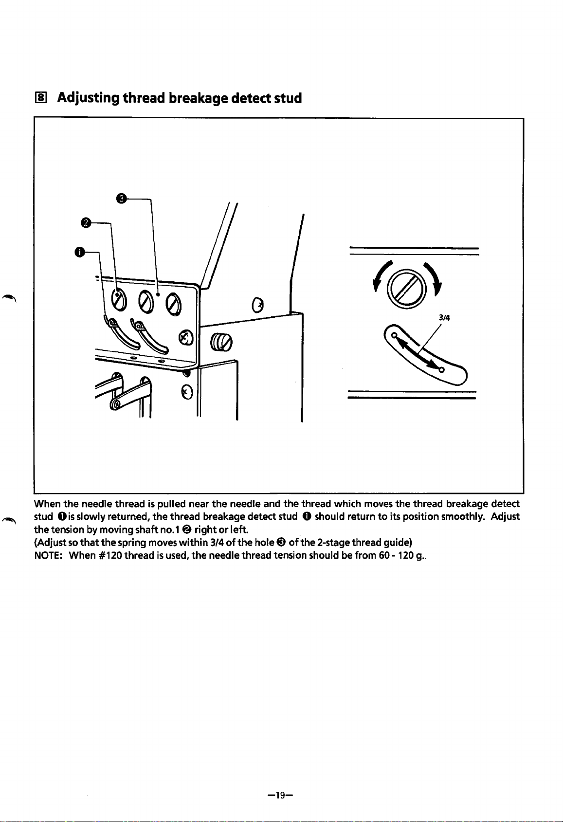
[!] Adjusting thread breakage detect
stud
3/4
When
stud
the
{Adjust
the
needle thread
Ois
slowly returned,
tension by moving shaft no.1@
so
that
the
spring moves
NOTE:
When #120 thread
is
the
pulled near
thread breakage detect stud 0 should return
within
is
used,
the
needle and
right
or
left. _
3/4
of
the
the
needle thread tension should be from
hole@)
the
thread which moves
of
the
2-stage thread guide)
the
thread breakage detect
to
its position smoothly. Adjust
60-
120 g ..
-19-
Page 23
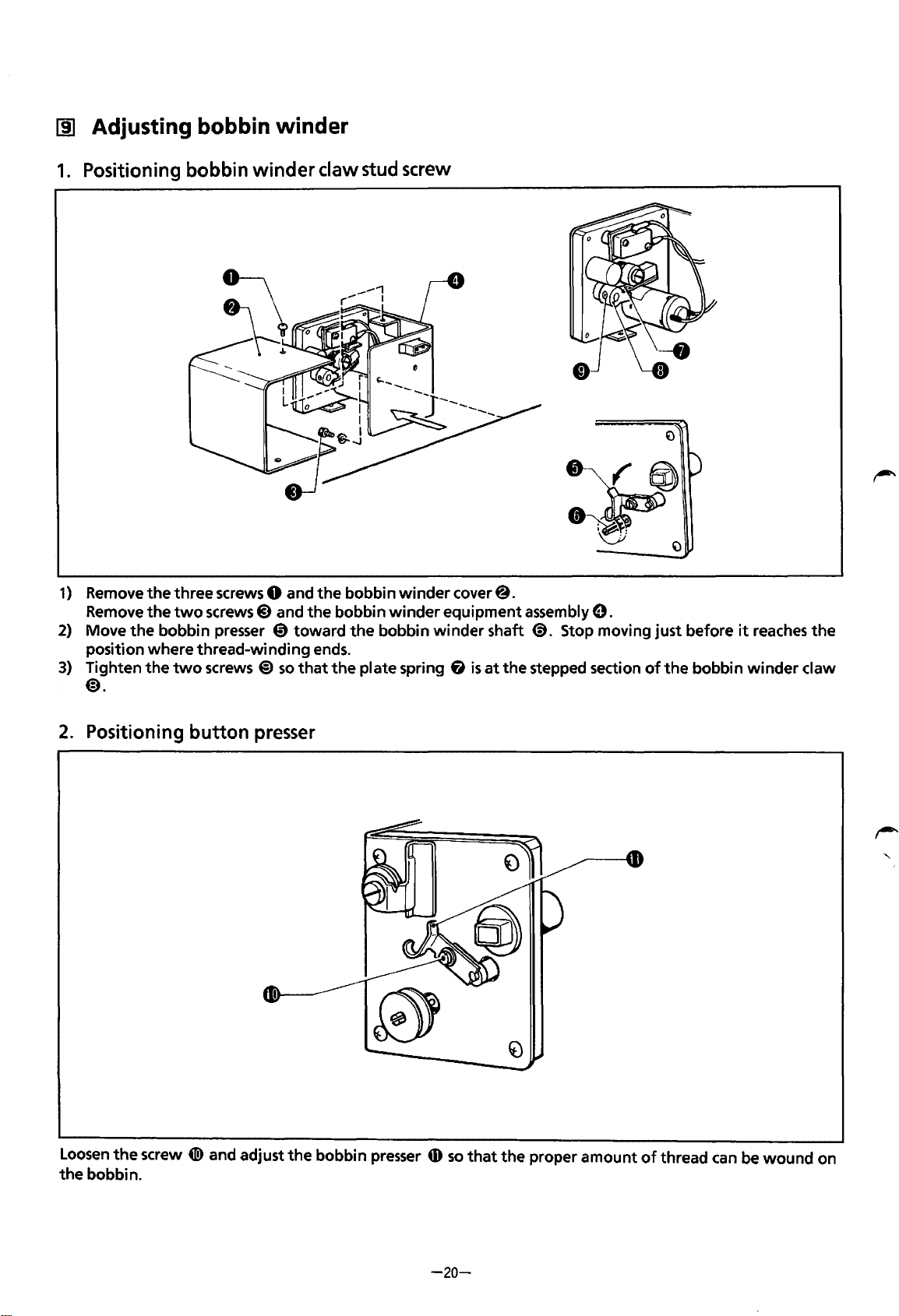
[j] Adjusting bobbin winder
1.
Positioning bobbin
winder
claw stud screw
1)
Remove
Remove
2)
Move
position where thread-winding ends.
3)
Tighten
the
three screws 0 and
the
two
screws 8 and
the
bobbin presser @)toward
the
two
screws
@)
so
@).
2.
Positioning
button
presser
the
the
that
bobbin
bobbin
the
bobbin
the
plate spring
winder
winder
cover@.
equipment assembly
winder
fi
shaft
<9.
is
at
the stepped section
9.
Stop moving just before
of
the
bobbin
it
reaches
winder
the
claw
Loosen
the
the
bobbin.
screw
41!)
and adjust
the
bobbin presser
tD
-20-
so
that
the
proper
amount
of
thread
can
be
wound
on
Page 24
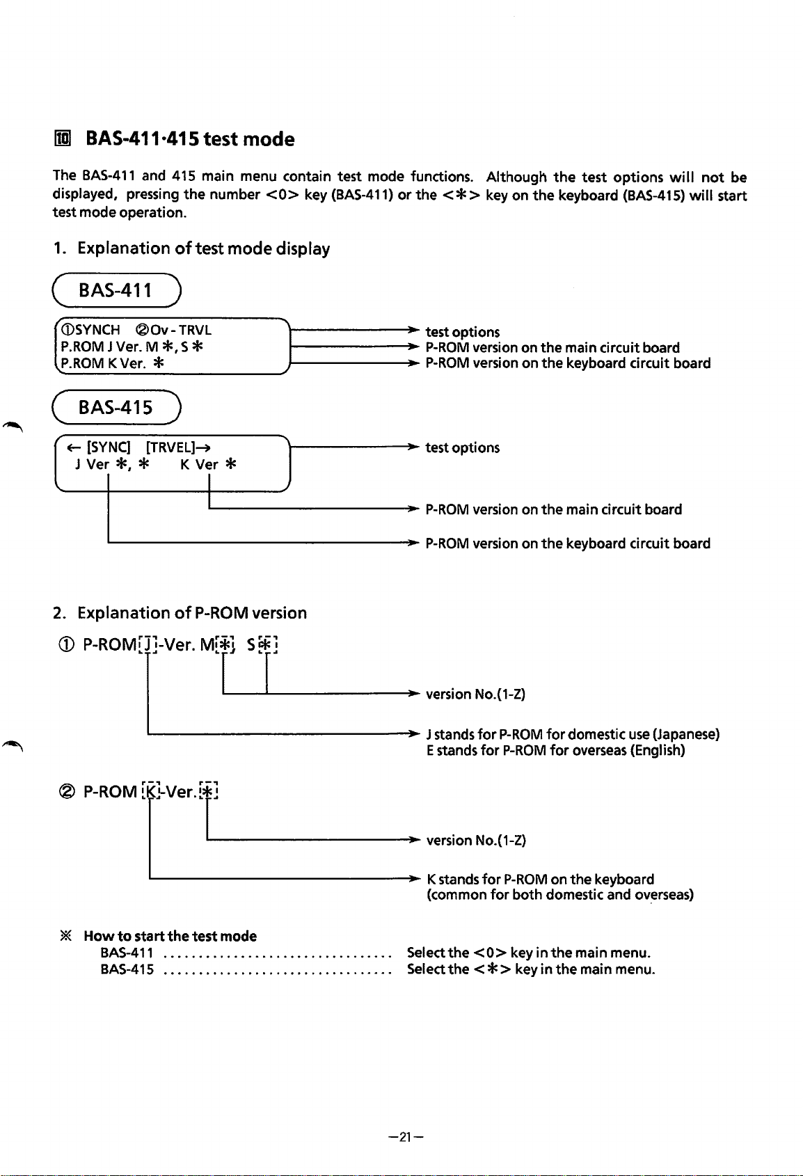
rml
BAS-411·415 test mode
The
BAS-411
displayed, pressing
test mode operation.
1.
Explanation
(
BAS-411
/
(i)SYNCH
P.ROM
P.ROM
and 415 main menu contain test mode functions. Although
the
number
of
test mode display
)
®Ov-
J Ver. M
K Ver. *
TRVL
*•
S *
( BAS-415 )
<0>
key
(BAS-411)
l--------J~~oo-
1------~_..~
1--------J~~oo-
or
the<*>
test options
P-ROM
P-ROM
the
test
options
key on
version on
version on the keyboard circuit board
the
keyboard
the
main circuit board
(BAS-415)
will
not
will
be
start
~
[SYNC]
J Ver
*,
'------------------J~~oo-
2.
Explanation
CD
P-ROM[]J]-Ver.
®
P-ROM
[TRVEL]~
* K Ver *
I
IL...------------J~~oo-
of
P-ROM
version
M[*r.j_S~.....__r]
- - •: version No.(1-Z)
[K[}Ver.[r.__]
_______
- : version
\--------"'JIIoo-
___
test options
P-ROM
P-ROM
....,.
- J stands
E stands
_....,..
version on
version on
for
P-ROM
for
P-ROM
No.(1-Z)
the
main circuit board
the
keyboard circuit board
for
domestic
for
overseas (English)
use
(Japanese)
'---------------~-
*
Howtostartthetestmode
BAS-411
BAS-41
.................................
5 . . . . . . . . . . . . . . . . . . . . . . . . . . . . . . . . . Select
K stands
(common
Selectthe<O>keyinthemainmenu.
-21-
for
for
the
< * > key in
P-ROM
on the keyboard
both domestic and
the
main menu.
ov~rseas)
Page 25
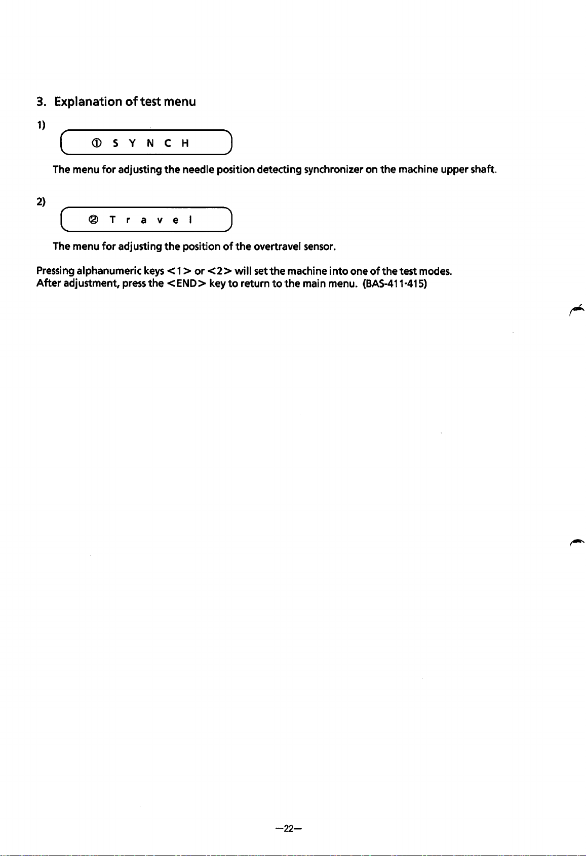
3.
Explanation
1)
of
test menu
( ____
The
2)
(
____ ® ___
The
Pressing
After
adjustment,
~
___ s __ v __ N
menu
for
adjusting
r
___
r
menu
for
adjusting
alphanumeric
press
__
c ___ H
the
needle
__ a __ v ___ e __
the
position
keys < 1 >
the
<END>
_____
position
l
____
_,)
of
or
< 2 > will set
key
)
detecting
the
overtravel sensor.
the
to
return
to
synchronizer
machine
the
main
on
the
machine
into
one
of
the
test
modes.
menu. (BAS-411·415)
upper
shaft.
-22-
Page 26
IDJ
Adjusting synchronizer
The
synchronizer detects
base.
When
thread trimming,
the
1.
the
emergency stop operates
the
same position
as
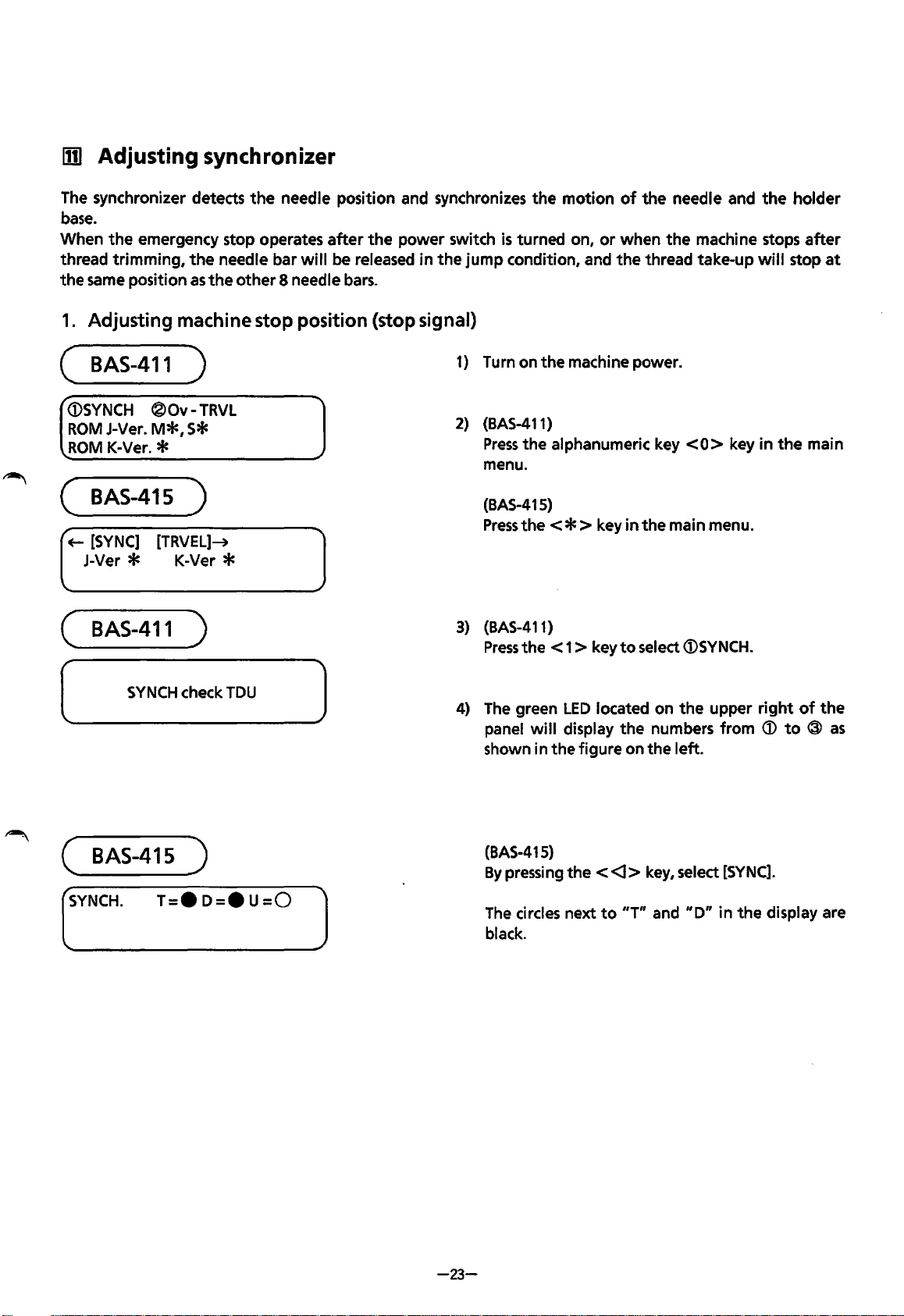
Adjusting machine stop position (stop signal)
the
needle bar
the
other
needle position and synchronizes
after
the
power switch
will
be released in
8 needle bars.
the
is
turned on,
jump
condition, and
the
motion
or
of
the
needle and
when
the
the
thread take-up
the
machine stops
will
stop
holder
after
at
(
BAS-411
<DSYNCH
ROM
ROM
(
BAS-415
+-
[SYNC]
J-Ver * K-Ver *
(
BAS-411
(
®Ov-
J-Ver.
M*,
K-Ver. *
SYNCH
S*
[TRVEL]-+
check
)
TRVL
)
)
TDU
)
1) Turn on
2)
(BAS-411)
Press
the
menu.
(BAS-415)
Press
the<*>
3)
(BAS-411)
Press
the
4)
The
green
panel
shown in
the
machine power.
alphanumeric key
key
in
< 1 > key
LED
will
display
the
to
located on
the
figure on
<0>
key
the main menu.
select
<DSYNCH.
the
upper
numbers from
the
left.
in
the
right
<D
to ® as
main
of
the
(
BAS-415
(_SY_N_C_H·
__
)
T_=_·_D_=_•_U_=_O
__
(BAS-415)
By
pressing
The
]
-23-
circles next
black.
the < <l>
to
"T"
key, select
and
"D"
[SYNC].
in
the
display are
Page 27
Timing pulse ® Needle do
Curved mark
si
gnal@
wn Nee
si
gnal @
dl e up
Stop
mar
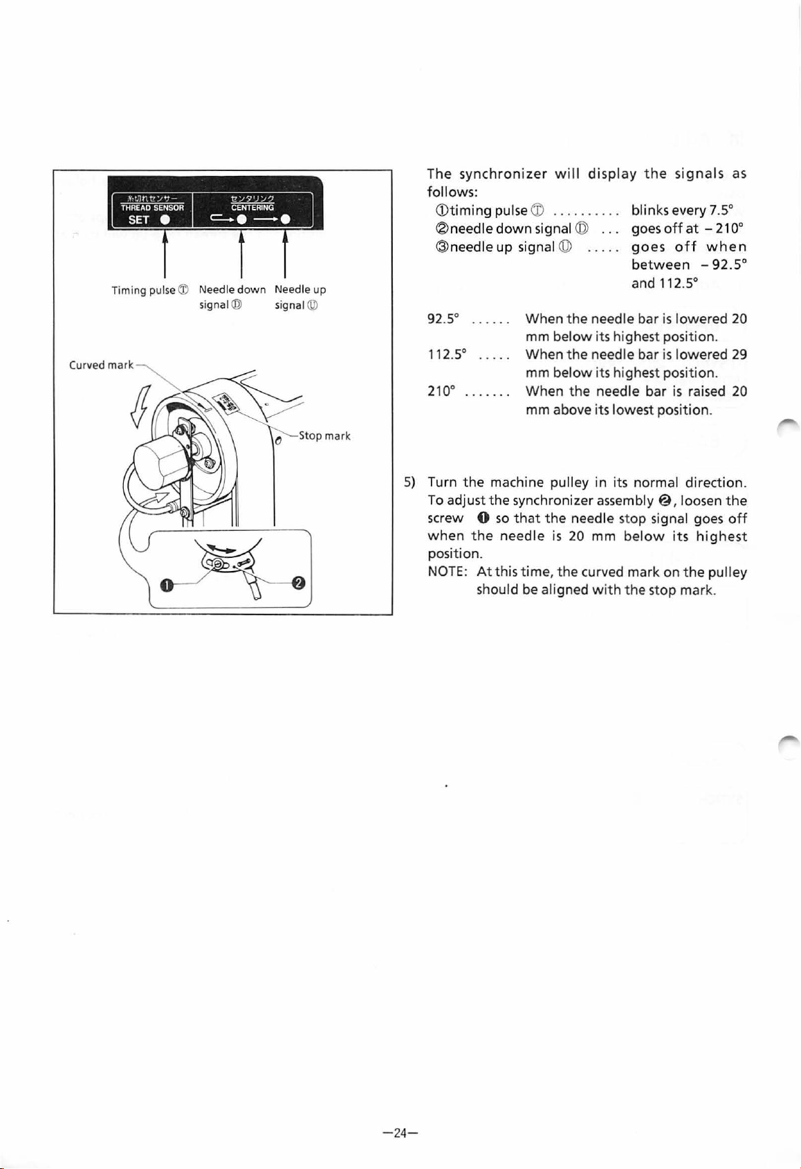
The
synchronizer will
display
the
signals
as
follows:
bl
in
<D
timing
® needle
@needle
pulse
CD .........
down
signal ©
up
signal @
..
.
goes
.
goes
between
ks every 7.5°
off
at -21
off
when
-92.5
oo
°
and 112.5°
92
.5° . . . . . . When t he needle bar
mm
112S
210
° . . . . . . .
below
When the
mm b
When
its highest position.
needle bar is lowered
elow
its highest
the needle bar
is
lowered 20
positio
is
n.
raised
29
20
mm above its lowest position.
k
5)
Turn
the
machine pulley in i
To adjust
sc
rew 0 so that
when
pos
NOTE:
the ne ed
ition
At
the
.
this time, the curved mark on
should
synchronizer
the
needle s
le
is
20 mm bel
be aligned wi
ts
normal direct
assembly@
top signal goes
ow its
th th
e st
op
ion
, loosen the
off
highe
st
the
pulley
mark.
.
-24
-
Page 28
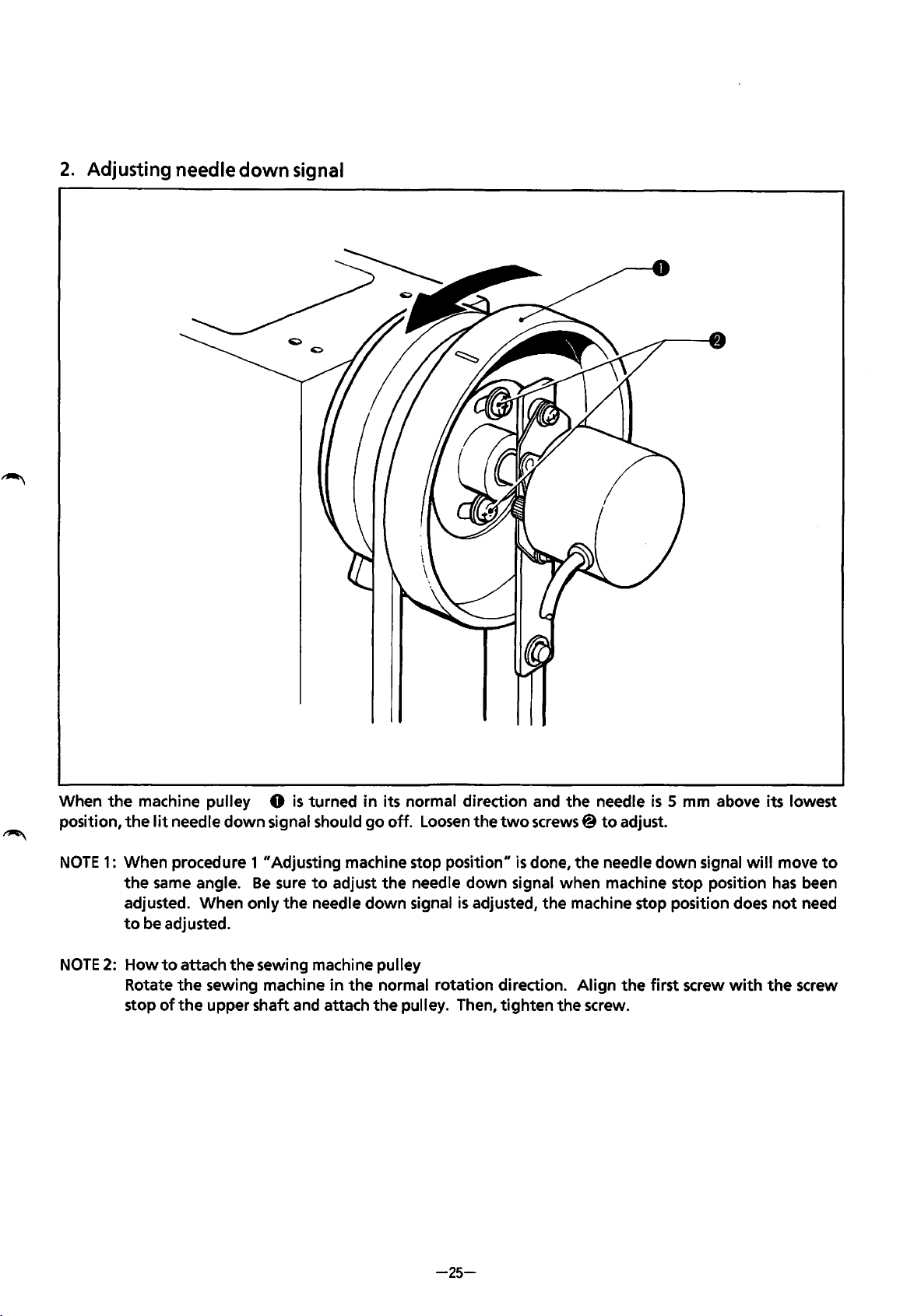
2.
Adjusting needle down signal
When
position,
NOTE
NOTE
the
1:
2: How
machine pulley 0
the
lit
needle
When procedure 1 "Adjusting machine stop position"
the
same
adjusted. When only
to
be adjusted.
to
Rotate
stop
the
of
down
angle.
attach
the
the
sewing machine
upper shaft and attach
is
turned
signal should
Be
sure
to
the
needle
sewing machine pulley
adjust
in
the
in
its normal direction and
go
off.
the
down
normal rotation direction. Align
the
pulley. Then,
Loosen
needle down signal when machine stop position
signal
the
two
is
adjusted,
tighten
screws@
is
done,
the
the
needle
to
the
needle
machine stop position does
the
screw.
is
adjust.
down
the
first screw
5 mm above its lowest
signal
with
will
move
has
not
the
to
been
need
screw
-25-
Page 29
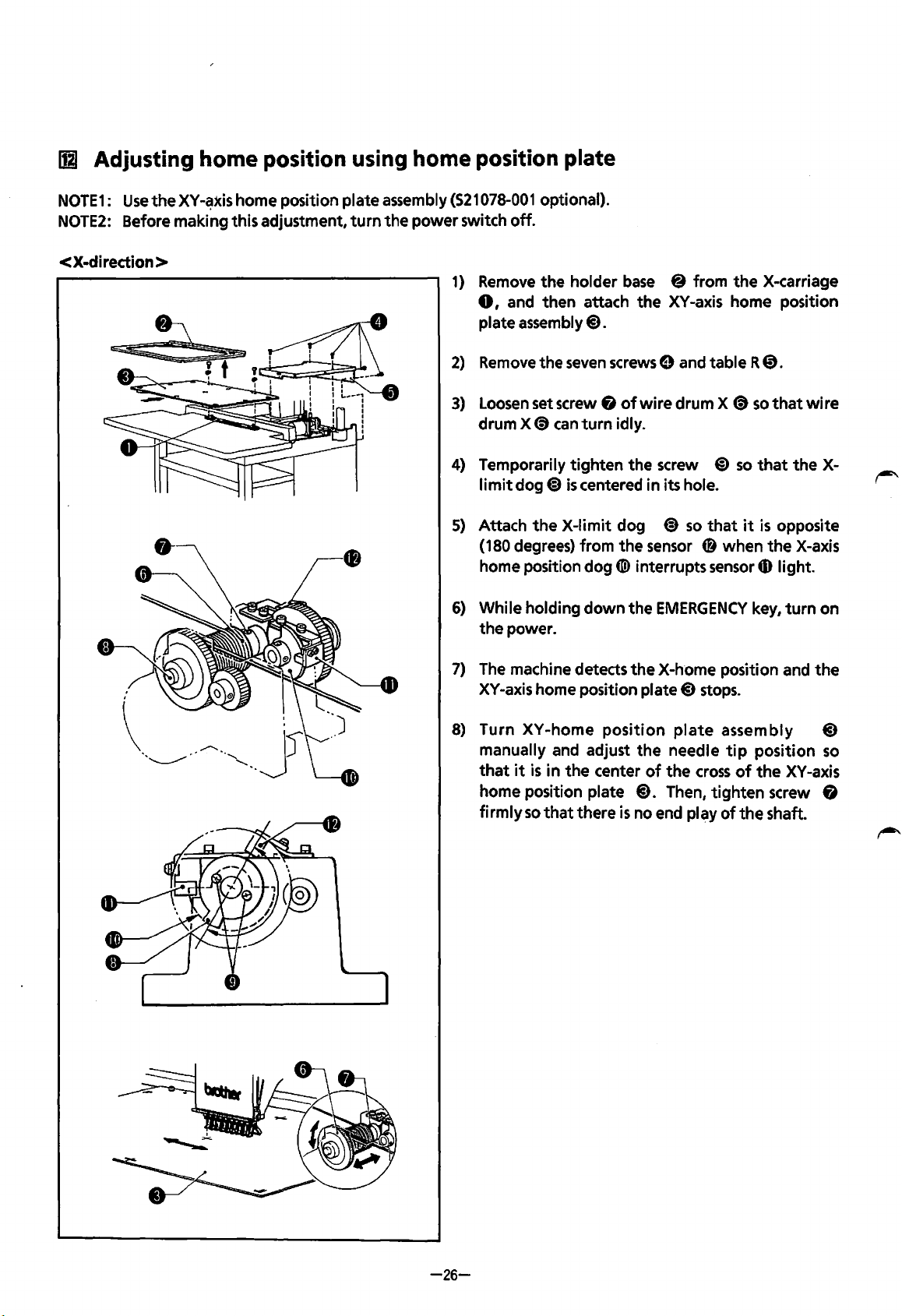
Ill
Adjusting
home
position using home position plate
NOTE1:
NOTE2:
Use
the
Before making this adjustment,
< X-direction >
XY-~xis
home position plate assembly
turn
the power switch
(521078-001
1)
Remove
0,
plate
2)
Remove
3)
Loosen
drum X
4)
Temporarily tighten the screw
limit
5)
Attach
(180 degrees) from
home position
6)
While holding down the
the power.
optional).
off.
the holder
and then attach the
assembly@).
the
seven
set screw &
<9
can
dog~
is
the
X-limit dog
base
screws
of
turn
idly.
centered in its hole.
the
dog([!) interrupts
8 from
XY
-axis home position
0 and table R
wire drum X
@)
~
so
that
sensor
CD
sensor
EMERGENCY
the
<9
so
so
it
when
key,
X-carriage
0.
that
wire
that
the
is
opposite
the
X-axis
4D
light.
turn
X-
on
7)
The
machine detects
XY-axis home position plate@)
8)
Turn XY-home
manually and adjust
that
it
is
in
the
home position plate
firmly
so
that
there
the
position
center
is
X-home position and
stops.
plate
the
needle
of
the
@).
Then, tighten screw &
no end play
assembly
tip
cross
of
position
of
the
the
XV
shaft.
the
@)
so
-axis
-26-
Page 30
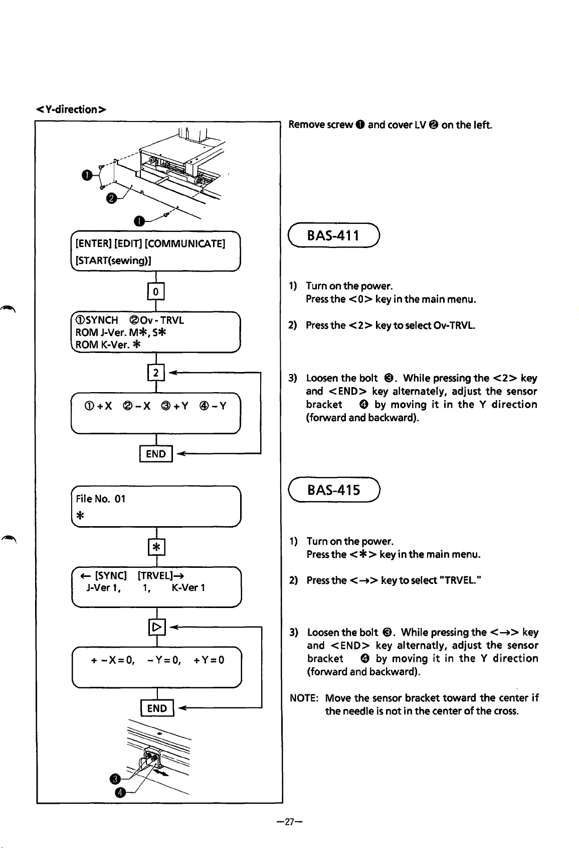
< Y·diredion >
[ENTER]
[START(sewing)]
[EDIT]
[COMMUNICATE]
Remove
(
1)
screw 0 and cover LV@ on the left.
BAS-411
Turn on the power.
Press
the
<0>
)
key in the main menu.
<DSYNCH
ROM
J-Ver.
ROM
K-Ver. *
<D+X
File
No.
01
*
~
[SYNC]
J-Ver 1 I 1
®Ov-
M*,
®-X
[TRVEL]-+
S*
1
TRVL
®+Y
K-Ver 1
@-Y
2)
Press
the
< 2 > key
3)
Loosen
and
bracket
(forward and backward).
(
BAS-415
1)
Turn on
Press
2)
Press
the
bolt
<END>
e by moving
the
power.
the<*>
the<-+>
key alternately, adjust
)
to
select
@).
While pressing
key
in
the main menu.
key
to
select
Ov-
TRVL.
the
it
in
the y direction
..
TRVEL.
..
<2>
the
key
sensor
3)
+
-X=
0,
- Y =
0,
+ Y = 0
Loosen
and
bracket
(forward and backward).
NOTE:
-27-
the bolt@). While pressing
<END>
e by moving
Move the sensor bracket toward
the
needle
the<-+>
key alternatly, adjust
it
j n
the y direction
is
not
in
the center
of
the
the
the
sensor
center
cross.
key
if
Page 31

!nl
Positioning over
limit
sensor
<Over
(
<X-direction
limit
BAS-411
[ENTER]
[ST
sensor
location>
)
>
[EDIT] [COMMUNICATE]
ART(sewi ng)]
1)
Press
the
numeric key
<0>
in
the
main menu.
CD
SYNCH ®Ov-
P-
ROM
J-Ver.
P-ROM
1---C_OD_E
CD
+X
CD
+X
SPEED
K-Ver. *
®
®
N_o
TRV
M*,
S*
-X
@
-X
@
.
~'21
'21
l!;_][g
L
+Y
+Y
ffilljl
L!JQJ
@
@
-Y
-Y
rpm.
2)
Press
the
3)
Press
the
move 227
displayed on
under
4) Loosen
so
that
figure
227 .5
pressed.
<2
> key to select ® Ov -
< 1 > key. The
.3
mm
to
the
the
panel and
the
number CD.
two
screws
the
thread sensor
on
the
display
mm
when
left
of
the
between
<E-->
hoop
and
. The
the
X-limit
indicator
and
TRVL.
the
holder
figure
cursor appears
dog
lights
227.0
<~>
base
"227
.3"
and adjust
with
mm and
keys
is
the
are
5)
Pressthe <END
-
28-
> key.
Page 32

I
<D+X
(j)
+X
®-X
¢
®-X
$$
®+Y
®+Y
@-Y
@-Y
~
6)
Press
the
move 227.3
displayed on
under the number
·
7)
Loosen
so
that
the
on
when
<2>
key.
The
mm
the
to
the
right.
panel and
hoop and
the
The
figure 11227.3
the
cursor appears
holder
0.
two
screws
the
centering indicator lights
display between 227.0 mm - 227.5 mm
jog
keys<~>
of
the
and
X-limit
<~>are
dog and adjust
pressed.
with
figure
base
..
is
CODE
SPEED
(j)
+X
'
<.DSYNCH
P-ROM
P-ROM
[ENTER]
[ST
J-Ver. MO,
K-Ver. 4
ART(sewi
No.
I
®-X
I
®Ov-TRVL
I
[EDIT]
ng)]
[2][2]~[31~
rpm.~
8)
Press
END
I
®+Y
END
SO
END
[COMMUNICATE]
®-Y
I
I
~
9)
the
11
CAUTION
and the holder
Press
the
menu.
<END>
MOVING!
base
<END>
Screws
key
twice.
II
is
displayed and
move
to
key again
the
to
The message
the
center.
return
to
the
hoop
main
-29-
Page 33

<Y·diredion>
[ENTER]
[START(sewi
<DSYNCH
ROM
ROM
t--~-~ED_E~_No_.
J-Ver. MO,
K-Ver.4
<D+X
<D+X
[EDIT]
(COMMUNICATE]
ng)]
®Ov-
®-X
®-X
TRVL
SO
®+Y
~+Y
----~[]~
@-Y
@-Y
8][5]
rpm.
1)
Press
the
numeric key
2)
Press
the < 2 > key
3)
Press
the
<3>
move 143.5 mm toward
"143.5"
appears under
4)
Loosen
position
with
-
144.0 mm when < f >
(143.5
is
displayed on
two
so
that
the
figure on the display between 143.0 mm
mm
desireble)
<0>
in
the
main menu.
to
select
®Ov-
key.
The
hoop and
the
the
the
number®.
bolts.
Adjust
the thread sensor indicator lights
TRVL.
the
holder
operator. The figure
panel and
sensor
or
<
J,
>
the
cursor
bracket
is
pressed.
base
A
<D+X
®-X
®+Y
@-Y
5)
Press
the
<END>
key.
-30-
Page 34

<D+X
®-X
I
®+Y
®-Y
6)
Press
the
<4>
key.
The
hoop and
move
figure
cursor appears under the number@.
143.5
11
143.5"
mm
away
from
is
displayed on the panel and
the
holder
the
operator. The
base
the
r
t--c_oo_E
SPEED
N_o.
<D+X
--~OJ~
I
END
®-X
I
END
8][5]
I
®+Y
I
_
rpm.~
®-Y
""'
7)
Adjust sensor
centering indicator lights
display between 143.0 mm • 144.0 mm
< f >
desireble)
8)
Press
main menu.
or
the
bracket B position
<
.L
>
is
pressed. (143.5 mm
<END>
key three times
with
the
so
that
figure on
to
return
the
the
when
most
to
the
(j)SYNCH
P-ROM
ROM
[ENTER]
[START(sewi
\..
J-Ver * MO,
K-Ver. *
[EDIT]
®Ov • TRVL
SO
*
I
END
I
[COMMUNICATE]
ng)]
-31-
Page 35

( BAS-415 )
<Y-diredion>
File No.
01
*
+--
[SYNC]
J-Ver
+
-X=O, -Y=O,
+
-X=O,
length
+
-X=O,
length
[TRVEL]-+
1, 1,
-Y=O,
-Y=O,
K-Ver 1
+Y=O
+Y=O
= 143.5 mm
+Y=•
= 143.5 mm
1)
Press
the
< * > key in
2)
Press
the<
I>> keytoselectTRAVEL.
3)
Press
the
<V
> key. The hoop and
base
move 143.5 mm
figure 11143.5
4)
Press
the
adjust
circle
of
between 143.0 mm and 143.7 mm.
11
is
<V
> key again. Loosen
the
sensor bracket A position
the
..
+ Y
the
toward
displayed on
=0"
turns black
main menu.
the
operator and
the
display.
two
when
the
holder
bolts and
so
that
length is
the
the
5)
After
adjustment,
+
-X=O,
+
-X=O, -Y=O,
length
-Y=O,
= 143.5 mm
+Y=•
+Y=O
-32-
6)
Press
the
<6
base
move 143.5 mm away
the
figure 11143.5"
7)
Press
the
<6
adjust
circle
between 143.3 mm and 143.7 mm.
the
sensor bracket B position
of
the
press
the<
END> key.
> key.
The
from
is
displayed on
hoop and
> key again. Loosen
11
-Y=O
..
turns black
the
the
operator and
the
display.
two
bolts and
so
when
holder
that
the
length
is
Page 36

+
-X=O,
+
-X=O,
length
-Y=e,
= 143.9mm
I
I
END
I
-Y=e,
I
+Y=O
+Y=O
8)
After
returns
pressing
main menu.
adjustment, pressing the
the
machine
it
three times returns
to
its home position and
<END>
the
machine
key twice
to
the
"
CAUTION
"
+-
[SYNC]
J-Ver
r
File
No.
*
"
<X-diredion
MOVING
1,
01
>
I
I
END
I
I
[TRVEL]-+
1,
K-Ver 1
I
I
END
I
I
""'I
.I
File
No.
01
*
+-
[SYNC]
J-Ver
-X=O,
+
+
-X=O,
length =227.3mm
1,
[TRVEL]-+
1,
-Y=O,
-Y=O,
K-Ver 1
+Y=O
+Y=O
1)
2)
3)
Press
the
< * > key in the main menu.
Press
the<
Press
the < <l > key.
base
move
11
227.3
11
is
Screws
I>> keytoselectTRAVEL.
The
hoop and
227.3
mm
to
the
left
displayed on the display.
and
the
the
holder
figure
-33-
Page 37

+
-x=e,
length =227.3mm
+
-x=e,
+
-X=O,
length
+
-X=•,
length
-Y=O,
-Y=O,
-Y=O,
=227.3mm
-Y=O,
=227.3
+Y=O
+Y=O
+Y=O
+Y=O
mm
4)
Press
the <
<l
> key again.
the X-limit dog and adjust
II+
-X=
Oil
turns black when length
227.0
mm
and
227.5
5)
After adjustment,
Press
6)
7)
the <
base
move
11
227.3
Press
the<[>>
the X-limit dog
II+
-X=0
227.0
mm
I>
>
227.3
11
is
displayed on the display.
and
11
turns black when length
and
227.5
mm.
press
the
key.
The
mm
to
the right and the figure
key again.
adjust
mm.
Loosen
so
that
<END>
hoop
Loosen
so
that
two
screws
the circle
is
between
key.
and
the holder
two
screws
the circle
is
between
of
of
of
the
~
of
the
+
-X=•,
CAUTION
+-[SYNC]
J-Ver
1,
File
No.
01
*
-Y=O,
MOVING
[TRVEL]-+
1,
I
I
END
I
+Y=O
K-Ver 1
I
8)
After adjustment,
returns the machine
pressing
main menu.
.)
it
three times returns the machine
pressing
to
the
<END>
its home position and
key twice
to
the
-34-
Page 38

rHI
How
If
the
thread sensor does
to adjust thread sensor (thread breakage detector)
not
function
:
1)
Make sure
on.
2)
Remove
that
bar position.
the
that
the
adjustment
swit
ch
the
thread sensor
@ indicator lights
base
indicator
~
and make sure
at
each needle
0 is
I
I
0 X
Stud
0 X
3)
If
the
indicator
most needle bar positions, adjust the switch @
position.
4)
If
the
indicator
specific
detect stud
NOTE
needle bar, adjust its
: Do
of
the
switch @ does
of
the
switch @ does
0
by
gently
not
overbend. The stud 0 may break.
bending it
not
thread
with
not
a plier.
light
at
light
at
a
breakage
-
35-
Page 39

c
LUBRICATION)
II1
Machine
head
Lubrication
Everyday before using
NOTE:
1)
Lubricate these six places:
is
necessary
<DBe
sure
to
use
®Overlubrication may
for
keeping
the
machine, add
Brother-specified sewing machine oil
cause
the
machine in good condition.
1-2
oil
to
drop(s)
drip
on
to
of
oil
the
at
each location in
for
lubrication.
material.
the
figure marked by an arrow.
2)
Add a
drop
of
oil
at
the
reel
of
the
NOTE:
3)
Do
not
lubricate aside from
Lubricate
needle bar. (18 places should be lubricated
two
places
on
the
each
rotary hook.
rotary hook.
needle
on
in
the
all.)
-36-
Page 40

4) Move
apply one
When
the
needle bar
or
the
machine
two
case
drop(s)
is
used
all
the
way
to
the
right
or
the
left
side. From
of
grease
every day, lubricate daily before using. ·
to
the
base
needle bar and
the
base
the
side
of
needle bar felt.
the
machine head,
-37-
Page 41

~
Feed
guide
mechanism
linear
guide rail: X· axis
Linear guide
rail: Y· axis
NOTE
NOTE
NOTE
NOTE
1: For
2:
3:
4: Before
lubrication,
Be
sure
After
applying
use
Brother-specified grease
to
lubricate every 6 months.
grease
applying
to
the
grease, remove covers
X·Y
guide
tank
rail, move
to
make
-38-
30.
the
the
work
X carriage
easier.
right
and
left
2-3 times.
Page 42

c
REPLACING
lii
Removing
AND
and
adjusting
ADJUSTING
machine
head
PARTS
(1)
)
1)
Remove
2)
Remove
3)
Remove
4) Loosen
to
the
X-carriage cover
the
belt & from
the
wires
from
the
four
nuts @)securing
the
machine head, remove
0,
table (R)@,
the
pulley (i).
the
curcuit board,
the
the
table
the
synchronizer, and
sewing machine
machine head.
(L)@),
-39-
base
and
@.
belt
covers (A) e and (B)@ in
the
With
ground.
the
sewing machine
that
base
@ attached
order.
Page 43

~
Removing
and
adjusting
machine
head
(2)
1)
2)
3)
Use
the
four
nuts@
Be
sure
to
have
The
distance from table
Use
the
two
rear
After
adjustment, tighten
and@)
an
approximately 2 mm
nuts@)
on the
(C)~
to
to
adjust.
the
four
base 0 to
space
the
end
of
the
nuts@ and@).
adjust.
between
cyrindrical
nut
9 and
bed®,
nut
0 when adjusting.
and distance® should
be
the
same.
-40-
Page 44

[II
Removing needle bar
case
Before replacing parts related
1)
2)
3)
Loosen
Remove
Adjust
the
four
the
four
the
needle bar
screws@
screws e
case
to
the
needle bar mechanism, be sure
of
the
thread presser base
of
the
needle bar
@)so
that
it
moves
case@)
right
0.
and
and
the
left
to
case.
slightly
remove
when
the
needle bar
attached
with
case.
four
screws.
-41-
Page 45

[j] Replacing up and
down
motion parts
1)
Loosen
2)
Move
or
3)
Loosen
Remove
above.
4)
Remove
5)
When assembling, reverse
NOTE1:
NOTE2:
NOTE3:
the
four
screws@ on
the
thread take-up shaft
2 thread take-up lever(s) 0 and thread take-up stopper(s)
the
screw & on
theE
ring @)attached
the
up
and
down
When attaching
which
When attaching
there
that
wi
II
is a 0.5
Make sure
it
is
in
be
that
the
the
right
and
the
@)
and
the
thread take-up supporter shaft 0
the
bottom
motion parts
the
the
attached
the
mm
space
the
thread take-up stopper
thread take-up support
of
the
right
to
the
main needle bar
([i)
from
above procedure.
main needle
to
the
thread take-up lever(s) 0 and
between
bar@,
main needle bar@).
@)
and
left
sides
side
of
the
the
connecting rod
secure
tD
or@)
CD
@.
(Fig.A)
of
the
<9.
arm.
@,then
the
and
does
bottom
of
the
thread take-up
30-
pull
out
the
4D.
bearing
the
@.
not
@by
pressing
thread take-up stopper
contact
the
thread take-up lever 0 and
base
40 mm, and remove 1
main needle bar
it
with
theE
<9,
fix
0.
@from
ring
them
@)
so
-42-
Page 46

[§]
Replacing
jump
solenoid
0.2mm
..
1,
..
I
7.2mm
1)
Loosen
2)
Remove
3) Remove
4) When assembling, reverse
NOTE1:
NOTE2:
the
set screw@
the
two
set screws e from
the
nut~
The end
distance between them
Adjustment references:
When
mm.
When
mm.
To
base@).
the
the
avoid mispositioning
of
of
the
of
the
solenoid
solenoid rod
solenoid rod
front
cover
(L)
0 and move cover
the
solenoid
solenoid @. Then, remove
the
above procedure.
@should
to
approximately 0.2 mm by moving
is
pushed,
is
returned,
of
the
solenoid,
cover@)
not
contact
the
distance between
the
distance between the end
do
the
not
(L) 0 to
and
the
solenoid
the
up and
remove
the
bottom left.
cover.
while
turning
down
nut~.
the
end
the
solenoid bracket
it.
motion parts
of
the
rod and
of
the
rod and
4.0mm
fi.
@)
the
the
or
Adjust
nut
nut
the
bracket
is
is
the
7.2
4.0
-43-
Page 47

(§]
Attaching X
wire
Carriage
1)
Position the carriage in the back, toward the
2)
Attach the wire end (the end closer
3)
Feed
the wire around pulley
from the
wind
4)
After
Then, put the
Fit the wire completely
5)
Feed
6)
Wind the wire
7)
Wind the wire over pulley (I) from above, then around pulley
Attach the wire
NOTE:
left
side,
and
over pulley
it
around pulley@ from the right.
winding the wire around pulley@, feed
ball on the wire into the hole
into
the groove, then wind the wire eight times around the wire drum.
the wire around the back
onto
pulley~
to
hook
(LX) @ with
Be
careful
durability.
not
to
scratch the wire.
to
the ball)
@)
from the
@).
of
pulley
from below, then around pulley
bolt
left
of
the machine, making
to
hook
left
side,
then under pulley
Then,
feed the wire around pulley & from the left, and finally
some
of
wire drum
tiD
I then around pulley m from the left.
4D.
The
wire
(RX) 0 with
slack
into the wire.
(X)@).
is
coated
bolt@.
@from
@from
with
resin
sure
0.
Then
the left.
the left.
and a
it
does
feed
scratch
not
move.
it
behind pulley @
may
decrease
r-"'
its
-44-
Page 48

[Z]
Attaching Y wire
Ywire(L)
1)
Push
2)
Use
the
3)
Put
the
Wind
Ywire(R)
1)
Pull
the
2)
Use
the
3)
Put
the
Wind
the
carriage 0
bolt 0 to
wire
onto
the
wire
carriage 0 forward and secure it.
bolt@)
wire
on
the
wire
to
the
back and secure it.
attach
pulleys 0 and(!). Then,
four
to
attach (Y)
to
four
times,
pulley
times,
(Y)
put
4).
put
wire
L@ end (the end furthest from the ball)
it
around
wireR
Then,
it
around pulleys@ and
put
the
wire
pulley~,
ID
end (the end closest
put
the
wire
then attach
ball
into
CD,
ball
the
into
the hole
it
to
stand
to
the
ball)
hole
of
wire
then, attach
to
of
(RL)@)
to
stand
drum (Y)
it
to
hook
wire
drum
with
(RR)
hook
(RY) @ with
(L
Y)@.
the
0.
@.
(Y)
6.
bolt(!).
the
bolt
@.
-45-
Page 49

c
ELECTRIC
IIJ
Circuit board locations
(
BAS-411
COMPONENTS
)
)
0 Main circuit board
@ PMD circuit board
@
Sew
ing machine
0 Synchronizer circuit board
0 Keyboard circuit board
motor
circuit board
( BAS-415 )
-
46-
Page 50

~
Replacing
circuit
boards
Main circuit board
Be
sure
to
turn
off
1)
Disconnect
2)
Press
Replace
3)
Place
support clamps
4)
Connect
Be
sure
15
the
six
circuit board support clamps inward and remove
the
main circuit board.
new
main circuit board on the supports. Secure the circuit board by pushing
the
connectors
not
to
Suppo:---n
the
power
connectors.
until
treat
and open
it
snaps
into
position.
while
supporting
the
circuit board forcefully.
the
cover before replacement.
the
circuit board from
the
main circuit board from
the
back side.
P13
down
the
supports.
near each
of
the
NOTE1:
NOTE2:
NOTE3:
NOTE4:
NOTES:
NOTE6:
When replacing connectors,
connectors.
Note
that
the
flat
cable
P13
direction.
Treat
the
circuit boards carefully.
Also,
do
not
touch
IC
pins.
Do
not
bend circuit boards. The circuit pattern
large size
Check
When
while
of
the
that
new
turning
holding
circuit board.
main circuit board
the
power
down
on
the
emergency stop switch. This clears
treat
them
c~refully.
is
directional {refer
for
MOS-IC
has a CPU
the
first
in
time
Do
to
the arrow).
the
circuit boards
or
IC
may
{HD64180) and
after
replacing
not
pull on
be
two
the
-47-
the
wires when detaching
It
can
not
be inserted in
is
easily damaged by static electricity.
broken by external force due
EP-ROMs{27512).
the
main circuit board, be sure
internal memory.
the
opposite
to
to
the
the
do
it
Page 51

PMD
pulse
motor
circuit board
1)
Disconnect the
2)
Push
the
inside and remove the pulse
Replace the pulse
3)
Place
supports. Secure
down
will
new
near each
snap
four
five circuit board supports towards
motor
pulse
of
into
position, securing the circuit board.
connectors.
motor
circuit board.
circuit board.
motor
the
the
circuit
circuit
supports. The support tips
board
board by pushing
on
the
the
Machine
motor
circuit board
1) Disconnect
2)
Push
the
four
inside and remove
board.
Replace
3)
Place
supports. Secure
down
will
the
new machine
near each
snap
into
the
three connectors.
circuit board supports towards
the
machine
machine
position, securing the circuit board.
of
motor
motor
the
the
circuit board.
circuit
circuit
supports. The support tips
motor
board on
board by pushing
the
circuit
the
-48-
Page 52

Synchronizer circuit board
1)
Disconnect
2)
Remove
3)
Remove the
Memory expansion circuit board (option)
the
connector
the
three screws@ and
four
screws 0 and the synchronizer circuit board
0.
the
circuit board attachment
base@).
0.
1)
Remove
board@.
NOTE:
four
screws 0 and then remove the memory expansion circuit board
When
circuit board
will
turning
be cleared.
on
@,
power
be
sure
of
BAS-411·415
to
do
it
while
holding down
for
the
first
time
after replacing
the
EMERGENCY
-49-
@from
the
switch. The inside memory
the
main circuit
memory expansion
Page 53

(
BAS-411
Keyboard circuit board {1)
)
1)
Manually loosen
2)
Loosen
At
3)
Disconnect
this
the
time,
the
two
screws@. Pull
do
not
pull strongly on
the
EMERGENCY
two
screws@
in
the
the
upper
the
EMERGENCY
switch 0 connector
keyboard cable 0 and remove it.
part
of
the
panel 0
stop switch@ cable.
C9
from
-50-
toward
the
keyboard circuit board
yourself and detach
fi.
it.
Page 54

Keyboard circuit board (2}
Pull
the
hatched part
the
flat
cable shown in
the
lock and pull
4) Disconnect
5)
Disconnect
6)
Loosen
the
panel
the
the
connector 0
the
flat
four
base
~.
cables@)
screws(!) on
from
and 0
the
the
keyboard circuit
from
the
right
and
left
board@.
keyboard circuit board @.
sides
of
the
supporter
-51-
0.
of
the
flat
Remove
the
black connector attached
the
figure on
cable
the
toward
key sheet
the
left.
yourself.
Release
fi
from
to
Page 55

Keyboard circuit board (3)
the
7) Loosen
8)
Remove
9)
When
screw@
the
four
assembling, reverse
so
screws@ and
that
the
knob 0
the
the
above procedure. For assembling, note
can
be removed easily. Then, remove
keyboard circuit board
0.
the
the
followin
knob
0.
g points.
NOTE
1:
NOTE2:
Attach
Align
Insert
the
Pull
If
and insert
the
the
the
hatched
the
flat
cable
flat
contrast
white
point
connectors
part
ofthe
cables 0
is
loose,
into
the
slots correctly.
knob 0 as
of
of
connector
and@
the
follows:
the
knob 0 with
White
point
the
flat
cab
to
lightly
cables may have been improperl y inserted
~Jjt
SPEED
les
0 and @
lock
to
che
the
position line. Tighten
.
while
it
in pl
ace.
ck
if
they
are locked properly.
ffv
the
screw@.
Position line
the
black connector lock
into
the
slots.
is
released. Insert
Release
the
lock
~
0
__.__..-
~~
~ " -
"
-----v
\ 0
-52
-
Page 56

Keyboard
unit
When rep I acing
1)
Manually loosen
2)
Remove
stand
Atthis
3)
When assembling, reverse
LCD
module
the
whole
the
the
four
screws 0 on
0.
time, be careful
assembmly
keyboard
two
screws@ in
not
to
the
\ _
unit,
follow
the
the
back side
drop
the
above procedure.
the
board cable 0 and remove it.
of
keyboard unit@).
_.
procedures below.
the
keyboard unit@). Then remove
it
from
the
keyboard
1)
2)
3)
4)
5)
6)
Loosen
Remove
Remove
Remove
Remove
Remove
two
screws@
two
screws@)
the
flat
four
screws@)
the
LCD
four
screws~
of
and
cables@)
and
module
and
the
keyboard cable 0 and remove
the
411
panel
0.
and
(S)
from
the
keyboard circuit board
the
support@).
assembly«!>
the
connector
LCD
module assembly
4D
-53-
from
«!>.
the
cable from the keyboard unit.
fj.
the
keyboard circuit board
fj.
Page 57

(
BAS-415
)
Keyboard circuit board (1)
1)
Manually
2) Loosen
At
this
3) Disconnect
loosen
the
time,
the
four
screws@). Pull
do
not
the
EMERGENCY
two
pull
screws@
strongly
in
the
the
upper
on
the
switch@) connector
keyboard cable 0 and remove
part
of
the
EMERGENCY
<9
panel 0
stop switch@) cable.
from
toward
the
keyboard circuit
-54-
it.
yourself and detach
board&.
it.
Page 58

Keyboard circuit board (2)
Pull
the
hatched part
the
flat
cable shown in
the
lock and pull
4) Disconnect
5)
Disconnect
6)
Lift
the
the
connector@)
the
flat
cable@)
from
from
the
keyboard circuit board
the
keyboard circuit board
key sheet support (!) and remove
it
from
the
panel
6.
6.
base
m.
-55-
the
ofthe
black connector attached
the
figure on
flat
cable
toward
the
left.
yourself.
to
Release
Page 59

Keyboard circuit board (3)
7)
Loosen
8)
Remove
9)
When assembling, reverse
the
the
screw@
four
screws@)
so
that
the
knob 0 can
and
the
keyboard circuit board
the
above procedure.
be
removed easily. Then, remove
0.
For
assembling, note
the
following
the
knob
points.
0.
NOTE1:
NOTE2:
Attach
Align
Insert
of
Pull
If
and insert
the
the
the
connector
the
flat
cable
the
flat
contrast knob 0
white
point
of
flat
cable 0 connector
to
.lock
cable 0
is
into
lightly
loose,
the
the slots correctly.
as
follows:
the knob 0
it
in place.
to
check
cables may have been improperly inserted
with
while
if
the
position line. Tighten
the
black connector lock
it
is
locked properly.
is
the
screw@.
released. Insert
into
the
slots.
the
hatched
Release
the
part
lock
-56-
Page 60

Keyboard
unit
When
1)
Manually
2)
Remove
stand
At
3)
When
LCD
module
1)
Remove
2)
Remove
replacing
the
loosen
the
four
whole
the
0.
this
time,
be careful
assembling, reverse
assembmly
the
connector@
three
screws@) and
keyboard
two
screws@
screws e
not
from
unit,
follow
in
the
on
the
back side
to
drop
the
keyboard unit@).
the
above procedure.
the
keyboard
the
LCD
module
the
procedures below.
board cable 0 and remove
of
the
keyboard
circuit
assembly e.
board
0.
unit
@).
it.
Then remove
it
from
the
keyboard
-57-
Page 61

~.
Fuses
1.
Position
of
fuses
F6
FS
F2
F1
Bobbin
winder
1)
Remove cover
2)
There
holder@.
NOTE:
2.
NOTE:
NOTE:
NOTE:
Be
Fuse
No.
F1
F2
F3
F4
F5
F6
Be
While
cool
During replacement,
(B)
0.
is
a fuse
sure
to
holder
turn
off
in
the
front
type and capacity
Fuse
type
& capacity
Fuse
15A S02887-000
Slow
blow
FuseB
Slow
blow
Fuse
B 152565-000
G
Fuse
5AFB
sure
to
use
only
fuses
the
circuit protector
for a while
before pushing
tightly
of
the
transformer in
power
fuse S11705-000
fuse S11705-000
before replacement.
of
authorized types and capacities.
is
activated,
it
back. Otherwise,
attach each fuse
the
the
power supply unit.
Part code
152565-000
S08030-000
thread
into
winding
it
may
its socket.
trip
motor
again.
Six
fuses are fixed
Reference
for
Pulse
for
Regulator
for
for
Bobbin
for
for
Sewing machine
will
not
rotate. Let
motor
Solenoid
winder
Lamp
in
motor
the
the
fuse
protector
-58-
Page 62

3.
Replacing fuse
The
following
When
replacing fuse, be sure
Fuse
problems occur
No.
if
the
to
use a new
fuse
is
blown.
one having
the
same
Problem
quality
and capacity
as
the
old
one.
F1
F2
F3
F4
FS
F6
Before replacing fuse 6, check
X and Y carriages
Home position detection
Operation panel display
Thread
Bobbin
Light
Sewing machine
Overload
trimmer
winder
marker
the
TR
do
not
move
at
all.
error
occurs.
is
blank
and
does
not
function.
motor
does
alley assembly referring
not
motor
does
light.
does
not
operate.
not
run
Using a tester, measure
If
the
If
the
alley assembly and
replacing fuse
the
sewing machine does
at
all.
to
below.
resistance
resistance
6.
is
not
is
either
the
not
operate.
the
resistance between + and
600,
it
is
defective.
00
or
oon,
replace
motor
circuit board instead
the
TR
of
Power
source
-59-
Page 63

[11
P-ROMs
( BAS-411 )
,~~,
Main
~
circuit board
0
D
oru
ID
ID
ID
0
oe
-
~6}
==:;;;;Ill§][]
Sewing machine
(common
, e
._
__
,..._..J
c::::J
OCJ
Keyboard circuit board
OE::::3
0
E=:J
for
all models)
[
r::::~Q
~0
0
motor
circuit board
( BAS-415 )
0
0
0~§
o®
0 °
DO
®
I I
0~~~
Main
EJ
00
DO
circuit board
0
D
oru
ID
0~
.
~
ID
([J
m
m
~
~
0
0
0
c::::3
c::::3
~o
Keyboard circuit board
0
D
-60-
Page 64

Be
sure
NOTES:
1.
Use
2.
Do
3.
Confirm
4.
Use
be used, be
sides.
to
turn
off
the
power
care when handling
not
apply excessive force when mounting the
that
the
PROMs
of
the
See
special
the
PROM
careful
figure.
before replacement.
the
PROMs.
are in
the
not
removal
to
damage
tool
Make sure
correct position and direction.
is
the
the
pins are properly inserted in
PROM
recommended when removing
PROM
socket. Carefully
on
the
circuit board.
lift
the
the
PROM
the
PROM.
little
sockets.
If
a screwdriver must
by
little
from both
Screwdriver
~
Circuit board
Socket
-61-
Page 65

1§1
DIP
(
BAS-411
switches
)
1.
SW1
At
shipping,
sewing area
Display
in
inches
DIP
can
~
~
~3
Fm:J
4
~
fmC~
m:::J
~8 ~8
~
5LV
6
1
ON
All dip
switches
before shipping.
Use
this
SW1
is
set
to
OFF.
be
specified in inches.
~1
~2
~3
Fm:J
~
fmC~
m:::J
are
setto
key
to
By
switching the
4
s
6
1
ON
OFF
choose
between
DIP
switch on, the total length
mm and inch
unit
system.
of
a pattern
or
the set
Example1
(ARA:
Example2 Totallength
(LG:
Example3
(HoP:
Area
V 10.10mm H 15.30mm )
V 10.00 mm H
To
set and confirm hoop feed
X 10.00 mm Y 15.00 mm J
15.00
mm J
point
-62-
This
indicates
inches ( = 257mm) and the horizontal length
15.30
inches ( = 389mm).
When setting the total
the data
0.01inches.
is
that
the vertical length
length:
in 4 digits, the minimum
is
unit
10.10
is
being
Page 66

Example
entry
When setting
Vertical
Horizontal
NOTE: In
the
vertical
0
1
using inches, errors
In
using millimeters, errors
2. SW2
o
SW2=0N
Pattern mode is displayed first.
length
1
3
for
3.5 inches and
5
1
1
I o I o I
within
Mode
mode using
0.254 mm should be tolerated,
within
switching
the
horizontal length
Press
numeric
ol
Press
ol
1 mm should be tolerated,
DIP
switch 2.
order
can
numeric
Enter degits in order
be changed by PATIERN key in
for
for
for
keys
keys
the
minimum
the
10
inches:
from
minimum
left
unit
unit
to
right
is 0.01
is
1 mm.
.
inches.
entry
oSW2=0FF
Alphabet
3. SW3
o When
When
stitch).
In this
In
entry
same
o
SW3=
The sewing start
Pattern mode
mode
is
displayed
Alphabet
mode
first
key
The sewing
switching
the
DIP
switch 3
the
entered data is one pattern,
case,
the
area check and
mode
or
as
when
the
OFF
when
SW3
point
is
ON
the
is
OFF
is
selected by
.
start
DIP
switch
the
test feed
entered data
.
the
centering function.
Alphabet
mode
Code mode
point
3.
the
needle location
function
is
two
patterns
key
of
are
the
embroidery
will
not
available.
or
more,
Code
Pattern mode
be
the
sewing start
the
sewing start
mode
can be
changed
point
point
will
(the
be
by
first
the
-63
-
Page 67

4.
SW4
oSW4=0N
Thread
oSW4=0FF
Thread
5.
SWS
oSWS=ON
Even
will
o
SWS=OFF
If
another
stop operation
· · · · · · · · ·
trimming
trimming
Use
this key
format)
will
not
will
be automatically done between characters. (Cross-over stitch
to
be done between characters. (Cross-over stitch
. . . . . . . . . Data reading
is
inserted
if
another
continue reading
floppy
floppy
at
disk
that
disk
is
inserted during data reading
or
sewing
is
inserted during data reading
point.
to
set
ON/OFF.
or
sewing
halfway.
until
it
is
the
done.
thread
can
be completed even
or
trimming
or
sewing
sewing
of
between characters (Brother
is
possible.)
is
not
possible.)
if
another
of
a character (pattern), machine
a pattern (character), machine
floppy
disk
will
NOTE:
6.
SW6-SW8
Do
not
errors
take
out
the
floppy
or
hinder correct sewing.
. . . . .
Not
available (Should be set
disk from
the
disk drive during data reading
to
OFF.)
or
sewing.
It
may
cause
-64-
Page 68

(
BAS-415
1.
Dip switch functions on main printed circuit board
)
WJD
~
~
l?%LJ
~
~
~
I?ZL)
~
1
2
3
.,.ON
4
I
5
6
sw
7
8
-
switch
SW1
SW2
SW3
SW4
sws
SW6
SW7
SW8
All dip switches are
number
state
OFF
ON
OFF
ON
OFF
ON
OFF
ON
OFF
ON
OFF
ON
OFF
ON
OFF
ON
set
to
OFF
before shipping.
To set paper
To set paper
To store data
To read and sew data
(Data cannot be stored
If
another
pattern
Even
if
of
a character (pattern), machine
until
it
To displav
To display sewing speed (rpm.)
Spare
Spare (Use
Spare
To display Japanese
To display English
tape
reading speed
tape
reading speed
of
floppy
floppy
(character), machine
another
is
done.
pattern
(Use
(Use
with
with
with
disk
floppy
name
OFF.)
OFF.)
OFF.)
disk
of
floppy
in
the
is
inserted
disk
of
function
to
9600 baud
to
4800 baud
in
the
memory
disk
memory.)
during
will
stop
operation
is
inserted
sewing data
will
durina
during
continue reading
sewina
data
reading
data reading
during
or
at
that
sewing
sewing
point.
or
sewing
or
sewing
of
a
NOTE:
The
If
the
power
power
of
the
machine should be
is
not
turned
off,
functions
turned
do
off
before changing switch.
not
change;
-65-
Page 69

2.
Dip switch functions on operation panel
switch
SW1
SW2
SW3
SW4
sws
SW6
SW7
SW7
number
state
OFF
ON
OFF
ON
OFF
ON
OFF
ON
OFF
ON
OFF
ON
To
jump
stitch
after
thread
trimming
To set
boring
To set boring mode
To set
boring
To set boring
To return
Not
to
return
To adjust
To adjust
To set sewing start
To
set sewing start
Spare
(Use
more
more
more
without
thread
mode
shift
shift
to
sewing start
to
timing
timing
with
function
SW1
than
--------
to
to
sewing start
of
of
point
point
·OFF.)
8 stitches
than
5 stitches
than
3 stitches
trimming
to
OFF
to
ON
OFF
(when
ON
(when
point
hoop
movement and needle rise
hoop
movement and needle rise
of
of
dip
dipsw 3 is
after
point
editing
editing
sw 3
sewing
after
system data
system data
OFF
ON
OFF
ON
is
ON)
ON)
sewing
to
to
center
for
for
first
thick
thin
stitch
of
SW2
OFF
OFF
ON
ON
material
material
mask
NOTE:
The
If
the
power
power
of
the
machine should be
is
not
turned
off,
functions
turned
do
off
before changing switch.
not
change.
-66-
Page 70

[II
Connectors
1.
Main circuit board connectors
Refer
to
the
control block diagram
to
check
the
connector locations.
Connector
No.
P1
P2
P3
P4
PS
P6
P7
Connecting
Not
available
Main circuit
Main circuit board +
-Power
board-
supply
point
Drive signals
--------------------
Solenoid Solenoid drive signal
SV
(whole
control
equipment
+ 12V
(RS232C)
- 12V
(RS232C)
+ 60V (Solenoid)
Main circuit board Pulse
- PMD circuit board
Main
circuit board Sewing machine
-Sewing
circuit board
Not
available
Main
-Synchronizer circuit board needle location signal
machine
circuit board
(P1)
motor
(P3)
motor
control signal
signal
--------------------
movement
needle
PCB)
motor
control
possible •
Symptoms resulting
from
bad
connection
----------------------------
Solenoid does
· Control function does
does
• Communication
• Solenoid
• X-axis pulse
• Y-axis pulse
•
Pulse
not
run. (Needle
· Sewing machine
• Thread
·Overload
----------------------------
Improper
case
· Needle bar
· Improper needle
• Improper needle
needle
not
motor
trim
does
bar
not
operate
does
not
motor
motor
for
mer
needle
not
move.)
case
is
selected.)
operate.
not
at
all.
function
operate.
does
not
does
not
needle
bar
bar
does
motor
does
does
not
bar
position (Needle
locking
bar
case
bar
position (Wrong
operate
does
function
position
well,
not
work.
run.
run.
replacing does
not
move.)
not
run.
.
or
bar
P8
pg
P10
P11
Main
circuit board Mechanical area
- Overtravel sensor displayed
Main
circuit board
- Y
home
position sensor
Main circuit board
-X
home
position sensor
Main
circuit board
-Thread
breakage detector)
sensor (Thread
Y-axis center detection
X-axis center detection
thread
Needle
over
signal
breakage signal
When
•
sewing area.
• During sewing,
although
· When
displayed.
· When
displayed.
· Thread breakage
• Thread breakage
-67-
power
although
the
power
power
is
turned
"area
needle
is
turned
is
turned
detector
detector
on,
"area
the
needle
over"
is
in
the
on,
"area
on,
"area
does
always activates.
over"
is
in
the
is
displayed
sewing area.
over"
over"
not
activate.
is
is
is
Page 71

Connector
No. connection
Connecting
point
Drive signals
Symptoms resulting
from
bad
P12
P13
P14
P15
P16
P17
P18
Main circuit
Main circuit board
-3.5
Main circuit board
- 3.5 in.
Main circuit board
-Editing
reader
Main
-Operation
Main circuit board
-Synchronizer
Main circuit board
-Rotary
board-
in.
floppy
floppy
system
circuit board
keyboard signal
encoder
cap sensor
disk drive
disk drive
or
paper
tape
cap
frame
overtravel signal
frame
cap
Input/Output
FDD
Serial comminucation control
signal be done. (Data cannot be received.)
Operation keyboard control
Needle
X-Y feed synchronize signal · Thread
home position signal
signal
power
supply
up
signal
of
FDD
Cap
frame
·
When
·
displayed.
· Machine cannot
·
FDD
· Data in floppy disk cannot
• Comminucation
· Data in
paper
· Nothing happens
· Display
· Synchronizing signal
· Timing pulse signal
· Hoop and holder base
or
X
home position
power
is
turned
does
not
function.
the
tape cannot be read
tape
reader.
is
blank.
trimming
Y direction.
on,
enter
cap frame mode.
with
editing system cannot
after
power
is
not
performed.
do
is
not
detected.
"overtravel"
be
read.
through
is
turned
not
move
is
on.
either
in
-68-
Page 72

2.
Sewing machine
Refer
to
the
motor
circuit board connectors
control block diagram
to
check
the
connector locations.
Connector
No.
P1
P2
P3
3.
X- andY-carriage pulse
Refer
to
Connector
No. connection
P1
Connecting
Sewing machine
board
-Power
Sewing machine
board
-Power
Sewing machine
board
-Main
the
supply
supply
circuit board
control block diagram
Connecting
Pulse
motor
circuit board
-Main
circuit board
point
motor
unit
motor
unit
motor
point
circuit 6V
drive signal)
circuit Sewing machine
signal
circuit Sewing machine
signal · Thread
(PS)
motor
(P4)
(PMD}
to
check
Pulse
Drive signals
AC
(Sewing machine
PCB
the
connector locations.
Drive signals
motor
drive signal · X-axis pulse
motor
motor
drive
motor
drive
connectors
Symptoms resulting
connection
• Sewing machine
· Thread
·Overload
· Sewing machine
· Thread
·Overload
· Sewing machine
·Overload
trimming
trimming
trimming
motor
is
not
motor
is
not
motor
is
not
Symptoms resulting
motor
does
· Y- axis pulse
·
Pulse
move.
motor
motor
does
for
needle bar change does
from
bad
does
not
run.
performed.
does
not
run.
performed.
does
not
run.
performed.
from
bad
not
move.
not
move.
not
P2
P3
P4
Pulse
motor
- Power supply
Pulse
motor
-XV
pulse
Pulse
motor
-Index
circuit board
unit
circuit board
motor
circuit board
motor
Pulse
motor
driving
Approx. + 37V
Y pulse
X and
control
power
Drive control
change pulse
power
motor
drive · X
supply
power
for
motor
· X
andY
home position
power
is
turned on.
· Unbalanced pattern
· Needle bar cannot be replaced.
· Needle bar
· Improper needle bar
andY
power
· Unbalanced pattern
needle · Needle bar cannot be replaced.
· Needle bar
· Improper needle bar
case
home position
is
turned on.
case
locking
case
locking
case
is
not
position
is
not
position
detected
detected
when
when
-69-
Page 73

[1]
Trouble
(
BAS-411
1. Symbols
shooting
)
flow
chart
1.
2.
3.
4.
indicates manual operation.
indicates switch operation.
selects
a yes-or-no decision-making process.
indicates
appears
determination and solution
the
in
course
that
the
the
first column
of
action
procedure
to
follow,
to
follow
of
"problem
table."
using
5.
6.
v
indicates setting-up operation.
indicates
appears on
0
7.
-70-
indicates
that
the
procedure
the
next page.
turning-off
the
to
power
follow
switch.
Page 74

2.
Troubleshooting
(1) When power
flow
is
turned ON:
chart
YES
·EJ
NO
YES
YES
NO
\
0
\
\
}
·EJ
·EJ
}
·EJ
}
·EJ
-71-
Page 75

(2) In data
entry
mode
[ENTER] [EDIT] [COMMUNICATE]
[START(sewing)]
Machine
goes
into
ENTRY
mode.
-72-
Page 76

(3)
In
sewing
mode
[ENTER]
[ST
[EDIT]
ART(sewi ng)]
[COMMUNICATE]
YES
YES
YES
\
\
}
·U
·U
}
·U
NO
-73-
·U
Page 77

YES
\
)
·EJ
YES
YES
YES
NO
YES
\
\
)
·U
)
·U
·U
·EJ
r-"
-74-
·EJ
Page 78

(4)
In communication mode
I
Communicate
I
Can't
communi
I Edit-sy busy
[ENTER] [EDIT]
[START{sewing)]
ERR
[COMMUNICATE]
-75-
Page 79

(5)
Electric
solenoid
[ENTER] [EDIT] [COMMUNICATE]
[START(sewing)]
YES
\
YES
\
YES
~YE~S
-~\'------'
YES
I
f
·U
-76-
Page 80

3.
Problem determination and solution
Precautions
1.
Be
sure
to
turn
off
the
2.
Be
sure
to
turn
3. Letters marked
items
should be checked
4.
When
5. Check
replacing a fuse, be sure
that
all harnesses and connectors are correctly connected.
power
off
the
power
with
an asterisk (ex. (a)*)
before plugging/unplugging
switch before opening
while
the
power
to
use a new
in
the
CHECK/ADJUSTMENT/REPAIR
is
applied.
one having
the
the
machine cover
the
same
power cord.
or
quality
and capacity
disconnecting cables.
column indicate
as
the
old one.
that
those
Before
1.
Check
2.
Confirm
making
that
the
adjustment
no
fuse
is
blown
problem area referring
and each plug
is
correctly inserted.
to
the
troubleshooting
flow
chart.
-77-
Page 81

NO.IN FLOW
AND
ERROR
CHART
STATUS
CAUSE
CHECK/ADJUSTMENT/REPAIR
PARTS
TO
REPLACED
BE
REF.
PAGE
#1
Keyboard ROM
displayed.
NG
is
#2
"CAUTION MOVING!"
is
not
displayed.
1. Keyboard
P-ROM
improper.
1. Power
is
not
2. Power switch
defective
version
supplied.
or
its cord
is
Replace
main
circuit
(a)*
Measure
If
the voltage
depending
Remove
power plug
Input terminals of the power
supply
unit.
Is
defective.
3. Regulator defective (a)* With
output terminal
normal. Similarly,
terminals.
4. Power harness defective (a)* While
and
they
normal.
5. Keyboard cable defective
6.
Operation
7.
Main
8.
Fuse
panel defective
circuit board defective
F2
blown
Check
In
double
Is
no
continuity,
Replace
Replace
Replace
that there
the
keyboard
board
voltage
on
face
cover
unconnected,
If
there
connector
If
connector
-12V
terminals
are
+
sv.
end
connector
operation
main
circuit board.
fuse.
P·ROM
with the
P·ROM.
of
single
phase
Is
not
100V
AC
where
It
Is
used.).lt
on
the left, turn
then
supply
Is
no
continuity, the power
P3
unplugged,
of
regulator.
check
the +
ltls + 12V
or·12V,It
P3
Is
plugged,
on
the
+
12V
and
·12Veach, they
Is
continuity between
of
keyboard
It
Is
defective.
panel.
one
matching
power
supply.
(120V,
220V,
240V
Is
defective.
on
the power with Power supply cord
measure
transformer Breaker
plug
and
power
measure + 5V
If It
Is
+
sv,
12Vand
·12V
Is
normal.
check + 5V, + 12V
main
circuit board.
are
same
numbers
assembly.
switch
It
Is
If
P-ROM
Regulator P92
Power supply P92
If
harness A
Main
Keyboard cable
there
Operation panel
Main
Fuse
of
keyboard
circuit board
circuit board
PSO
P96
PSO
P47
PSS
#3
"Missed
"MissedY-ORG.PT"
displayed.
X-ORG. PT"
:#4
"Overtravel"
displayed.
is
1. Pulse
motor
harness defective
or
is
2. Pulse
motor
power
defective
3. Pulse
motor
defective
4. PMD circuit board defective
5. Main circuit board
6.
Fuse
F1
blown
1. Home position sensor defective
Over
travel
2.
3.
Main
sensor defective
circuit board defective
supply
Check
that
connector
P41s
proper continuity tested for.
(a)* With
connector
P2
on
unplugged,
No.5(·).
Replace
Replace
Replace
Replace
Check
connected
Check
proper continuity tested for.
Replace
check
the voltage
If
It
Is
not
37V,
pulse
motor.
PMD
circuit
board.
main
circuit
board.
fuse.
that
that
main
connectors
and
connector
P9
proper continuity tested for.
PB
circuit board.
and
Is
correctly
PMD
circuit board
It
Is
defective.
P10
correctly
connected
of
pins
are
correctly
connected
No.1
and
Pulse
harness
Power supply
(
+)
and
Pulse
PMD circuit board
Main circuit board
Fuse
Home position
sensor
and
Over
Main
motor
unit
motor
travel
sensor
circuit board
P92
P92
P48
P47
P58
P93,94
P93
P47
-78-
Page 82

NO.IN FLOW
AND
ERROR
CHART
STATUS
CAUSE
CHECK/ADJUSTMENT/REPAIR
PARTS
TO
REPLACED
BE
REF.
PAGE
#5
"Disk
ERR."
displayed.
#6
."Short
of
displayed.
#7
"*th
data
displayed.
#8
"*th
Memory
displayed.
is
Area"
ERR."
OVR"
1. Floppy harness defective
FDD
power
2.
supply harness
defective
3. Floppy disk drive defective
4.
Improper media
5. Main circuit board defective
Mis-operation
Check
that
connector
P131s
proper continuity tested for.
(a)
Check
that
connector
P141s
proper continuity tested for.
(b)* With
connector
P14
removed,
between pin 1
defective.
Replace
(a)
Check
(b)
Check
replaced
Replace
Check
area
floppy
main
disk
that
It
Is
that
media
by
2HO,
circuit board.
and
ratio
(+)and
drive.
correct for
type
and
vice
In
editing
correctly
correctly
pin 2
machine.
Is
correct.
versa.
mode.
connected
measure
(-).
If
200
connected
voltage
It
Is
not +
cannot
and
Floppy harness
or
FDD
harness
SV,
It
Is
Floppy disk drive
Media
be
Media
Main circuit board
------------
power
type
supply
P94
P94
P94
P47
is
Improper
media
Check
media.
Replace media.
is
1. Mis-operation
is
2.
Memory
expansion board
Entered
cannot
Replace
data
be
managed.
memory
exceeds
expansion
the
Inside
board.
memory
capacity
and
·-----------
Memory
expansion P49
defective board
Replace
main
circuit
3. Main circuit board defective
board.
Main circuit board P47
#9
Hoop does
#10
not
move. Refer
Mis-operation
to
item
#3.
1. Encoder harness defective
Sewing machine runs
but
hoop
does
not
2. Rotary encoder defective
move. 3. Synchronizer defective
#11 1. Sewing machine
motor
Overload occurs board harness defective
immediately
sewing began.
after
2. Sewing machine
board
motor
3. Transistor alley defective
4.
Fuse
F6
blown
#12 Machinery defective
Overload occurs
automatic
trimming.
#13
Errors relative
bar
needle
appear.
thread
to
case
during
Refer
to
item
#11.
1. Index circuit board harness
defective
2.
Pulse
motor
harness defective
·Needle change
3.
p~lse
motor
defective
4. PMD circuit board defective
5.
Fuse
F1
blown
circuit
circuit
Area
Is
set too
small.
Re-edit
In
editing
mode.
Refer
to
Item #3.
Check
that
connector
P181s
correctly
connected
proper continuity tested for.
Replace
rotary
encoder.
Replace
synchronizer.
Check
that
connector
P17
Is
correctly
connected
proper continuity tested for.
Replace
sewing
machine
motor circuit
Replace
transistor alley. PS9
Replace
fuse.
Repair
and
adjust
machinery.
Refer
to
Item
#11.
Check
that
connector
P7
Is
correctly
proper continuity tested for.
Check
that
connector
P4
Is
correctly
proper continuity tested for.
Replace
pulse
motor.
Replace
PMO
circuit
board.
Replace
fuse.
board.
connected
connected
and
and
------------
Refer
to
item
and
Encoder harness P98
Rotary encoder
Synchronizer
Sewing
and
machine
circuit board
Sewing
circuit board
transistor
Fuse
Refer
harness
machine
and
alley
to
item
Index circuit board
harness
Pulse
motor
harness
Pulse
motor
PMD circuit board P48
Fuse
#3.
motor
motor P48
Refer
ltem#3.
P98
PSB
#11.
P93
P92
P58
to
-79-
Page 83

NO.IN FLOW
AND
ERROR
#14
Thread
CHART
STATUS
trimming
is
not
Refer
CAUSE
to
"(5) electric solenoid" in troubleshooting.
normal.
#15
Embroidery
is
1. Improperly adjusted machinery
2. PMD circuit board defective
distorted. 3. Mis-operation
CHECK/ADJUSTMENT/REPAIR
Re-adjust
machinery.
Replace
PMD
circuit
board. PMD circuit board
(a)
Check
If
machine
Is
operated
cap
sensor.
(b)
Check
If
machine
Is
operated
without
cap
sensor.
In
hoop mode with
In
cap frame
mode
PARTSTOBE
REPLACED
·-----------
------------
·-----------
REF.
PAGE
P48
#16 1. Improper
Errors relative
communication
appear.
#17
"Tape read Error"
displayed.
#18
Solenoid does
operate.
to
not
2. Paper
tape
3. Editing system defective
4. Main circuit board defective
1. Mis-operation
is
2.
lmpropertape
3. Tape reader defective
1. Solenoid harness defective
Solenoid
2.
3. Solenoid defective
4. Main circuit board defective
Improper machinery
5.
6.
Fuse
F3
blown
7. Refer
to
RS
cable
reader defective
power
defective
item
#10.
Check
that
RS
cable
Is
correctly
continuity tested for.
(a)
Check
that power
(b)
Check
that paper tape
(c)
Replace
(a)
Check
that power
(b)
Check
that
(c)
Replace
Replace
main
Select correct tape type.
(a)
Poor
punch
(b) Paper tape runs short.
(a)
Dirty
head
(b)
Replace
Check
connector
continuity tested for.
(a)*
With
connector
between pins 6
normal.
With connector
values of
pins
~
thread
ND.2
~
thread
No
A
jump
I
:~.!
I
No.7
picker solenoid
No.8
Each
voltage should have above spedfled
Replace
main
Readjust
machinery.
Replace
fuse.
Refer
to
Item
Is
paper tape reader.
Is
machine
editing
system.
circuit
board.
of
paper tape
of
paper tape reader
tape reader.
P2
Is
correctly
P3
unplugged.
(+)and 8 (·).
P2
unplugged. measure
below.
trimming
wiper
solenoid
drcult board.
#10.
connected and proper
turned on.
Is
set.
turned
on.
enters
communication
connected and proper
check
lflt
solenoid
solenoid
voltage
Is
+ 60V,Itls
resl$18nce
mode.
470
230
1850
6500
values.
RScable
Paper
tape
reader
Editing system
Main
circuit board
·-----------
Re-punch tape.
Clean head.
Tape reader
Power supply
Thread
solenoid
Thread
solenoid
unit
trimming
wiper
Jump solenoid
Picker solenoid
Main
circuit board
·-----------
Fuse
Refer
to
item
#10.
P47
P92
P92
P92
P47
P58
-80-
Page 84

(
BAS-415
1.
Symbols
)
1.
2.
3.
4.
indicates manual operation.
indicates switch operation.
selects
a yes-or-no decision-making
indicates
appears in
determination and solution
the
course
that
the
the
first column
of
action
procedure
to
follow,
process.
to
follow
of
"problem
table."
using
5.
6.
v
indicates setting-up operation.
indicates
appears on
0
7.
-81-
indicates
that
the
procedure
the
next page.
turning-off
to
the
power switch.
follow
Page 85

2.
Troubleshooting
{1) When
power
flow
is
turned ON:
chart
YES
NO
\
}
~EJ
~EJ
YES
YES
NO
\
}
~EJ
~EJ
~EJ
-82-
Page 86

(2)
In
data entry mode
FileNo.**
Machine goes
into
ENTRY
mode.
YES
YES
\
}
~Q
~Q
-83-
Page 87

(3) In sewing mode
FileNo.**
YES
YES
NO
\
}
~u
~u
~u
-84-
Page 88

\
}
~u
~u
\
\
}
·U
·[:/]
~u
}
·[:/]
-85-
Page 89

(4)
In communication mode
File
No.**
I
Line
ERR.
I Off line
I
Line
busy
---..-u
-86-
Page 90

(5)
Electric solenoid
FileNo.**
YES
~YES
~\"--------'7-
YES
YES
YES
-87-
Page 91

3.
Problem determination and solution
Precautions
1.
Be
sure
to
turn
off
the
2.
Be
sure
to
turn
off
the
3.
Letters marked
items should be checked
4.
When replacing a fuse, be sure
5.
Check
that
with
an asterisk (ex. (a)*)
all harnesses and connectors are correctly connected.
power
power
before plugging/unplugging
switch before opening
while
the
power
to
use a new
in
the
CHECK/ADJUSTMENT/REPAIR
is
applied.
one having
the
the
machine cover
the
same
power
quality
cord.
or
disconnecting cables.
column indicate
and capacity
as
the
that
old one.
those
Before making
1.
Check
that
2.
Confirm
the
adjustment
no
fuse
is
blown
problem area referring
and each plug
is
to
the
troubleshooting
correctly inserted.
flow
chart.
-88-
Page 92

NO.IN
FLOW
AND
ERROR
#1
Keyboard
displayed.
#2
"CAUTION
is
not displayed.
CHART
STATUS
ROM
NG
MOVINGI"
PARTS
TO
CAUSE
CHECK/ADJUSTMENT/REPAIR
BE
REPLACED
Change
CPU
version
of
keyboard
to
proper
1.
CPU
version
of
keyboard
is
incorrect.
1.
Power
is
not supplied.
2.
Power switch or its
defective
3.
Regulator defective
4.
Power
harness
defective
5.
Keyboard
6.
Operation panel defective
7.
Main circuit board defective
8.
Fuse
F2
cable
blown
defective
cord
is
matching
PROM
of
PCB.
(a)*
Measure
voltage of
single
phase
If
the voltage
depending
Remove
power plug
Input terminals
supply
unit.
Is
defective.
(a)* With
Output
normal.
terminals.
(a)* While
and
they
normal.
Check
that there
In
double
Is
no
continuity
Replace
Replace
Replace
on
face
cover
unconnected,
of
If
there
connector
terminal
Similarly.
If It
connector
·12V
terminals
are
+
sv.
end
connector
,It
operation
main
circuit
fuse.
Is
not
100V
where
It
Is
on
the left. turn
then
the power
Is
no
continuity. the power
P3
unplugged.
of
regulator.
check
Is
+ 12Vor-12V,It
P3
Is
plugged.
on
the
+
12V
and
Is
continuity
of
keyboard
Is
defective.
panel.
board.
AC
used.), It
measure
supply
the+
main
·12V
between
version
power
supply.
(120V,
220V,
240V
Is
defective.
on
the power with
transformer Breaker
plug
and
power
switch
measure
+
sv
If
It
Is
+ SV,It
Is
12Vand
-12V
Is
normal.
check
+
sv.
+
12V
circuit
board.
If
each.
they
are
same
numbers
assembly.
If
there
CPU
of
keyboard P54
Power supply
cord
Regulator P92
Power supply P92
harness
A
Main circuit board
Keyboard
cable
Operation panel
Main circuit board
Fuse
REF.
PAGE
P97
P57
P47
P58
1.
Pulse
#3
"X_ORG.Error"
"Y _ORG.Error"
or
is
2.
motor
Pulse
motor power supply
displayed. defective
3.
Pulse
motor defective
4.
PMD
circuit board defective
5.
Main circuit board
6.
Fuse
F1
1.
Home
#4
"Overtravel"
displayed.
is
2.
3.
position
Over travel
Main circuit board defective
harness
blown
sensor
sensor
defective
defective
defective
Check
that
connector
proper continuity
(a)*
With
connector
unplugged.
No.5(·).
If It
Replace
pulse
motor.
Replace
PMD
circuit
Replace
main
circuit
Replace
fuse.
Check
that
connectors
connected
Check
proper continuity
Replace
that
main
and
connector
circuit
P41s
correctly
tested
for.
P2
on
PMD
check
the voltage of
Is
not 37V,It
proper continuity
tested
board.
board.
P9
PSis
board.
Is
and
P10
correctly
for.
connected
circuit
board
pins
defective.
are
correctly
tested
connected
No.1 ( +)
for.
and
and
Pulse
motor
harness
Power
supply
unit
and
Pulse
motor
PMD
circuit board P48
Main circuit board P47
fuse
Home
position
sensor
Over travel
sensor
Main circuit board
P92
P92
P58
P93,94
P93
P47
-89-
Page 93

NO.IN FLOW
AND
ERROR
CHART
STATUS
CAUSE
CH
ECK/ADJUSTMENTIREPAIR
PARTSTOBE
REPLACED
REF.
PAGE
#5
"Disk
ERR."
displayed.
#6
"Short
of
displayed.
#7
"Data
ERR."
displayed.
#8
"Memory
displayed.
is
Area"
is
over"
Check
that
connector
P131s
correctly
P14
Is
vice
sewing
Is
correctly
measure
(·).
machine.
correct.
versa.
connected
connected
voltage
If It
Is
not + SV,It
200
cannot
area.
1. Floppy harness defective
2.
FDD
power
supply harness
defective
3. Floppy disk drive defective
4.
Improper
5.
Main
Improper
media
circuit board
sewing
data
defective
proper continuity tested for.
(a)
Check
that connector
proper continuity tested for. harness
(b)* With
connector
P14
removed,
between pin 1 (+)and pin 2
defective.
Replace
floppy
disk
drive.
(a)
Check
that
It
Is
correct for
(b)
Check
that
media
type
replaced
by
2HO,
and
Replace
main
circuit board.
Pattern
size
of data
exceeds
is
Improper
1. Mis:..operation
is
2.
Memory
media
expansion board
Check
Entered
cannot
Replace
media.
data
be
managed.
memory
exceeds
expansion
the
Inside
board.
memory
capacity
defective
3.
Main
circuit board defective
Replace
main
circuit
board.
Floppy harness
and
or
FDD
Is
Floppy disk drive
Media
be Media
Main
This
cannot be sewn.
Replace media.
and
------------
Memory
board
Main circuit board
power
supply
type
circuit board
pattern
data
expansion
P94
P94
P94
P47
P49
P47
#9
Hoop does
not
move.
#10
Sewing machine runs
but
hoop
does
not
move.
#11
Motor
is
locked
immediately
after
sewing began.
#12
Motor
is
locked
during
automatic
thread
trimming.
#13
bar
to
case
Errors relative
needle
appear.
Refer
to
item
#3.
1. Encoder harness defective
2. Rotary encoder defective
3. Synchronizer defective
1.
Sewing machine
motor
circuit
board harness defective
2. Sewing machine
motor
circuit
board
3. Transistor
4.
Fuse
F6
blown
~lley
defective
Machinery defective
Refer
to
item
#11.
1.
Index circuit board harness
defective
2. Pulse
3. Needle change pulse
motor
harness defective
motor
defective
4. PMD circuit board defective
5.
Fuse
F1
blown
Refer
to
Item
#3.
Check
that
connector
P181s
proper continuity tested for.
Replace
rotary
encoder.
Replace
synchronizer.
Check
that
connector
proper continuity tested for.
Replace
sewing
Replace
transistor
Replace
fuse.
Repair
and
Refer
to
Item
Check
that
connector
proper continuity tested for.
Check
that
connector
proper continuity tested for.
Replace
pulse
Replace
PMD
Replace
fuse.
adjust
#11.
motor.
circuit
P17
machine
alley.
machinery.
P7
P4
board.
Is
motor drcult board.
Is
Is
correctly
correctly
correctly
correctly
connected
connected
connected
connected
Refer
and
Encoder harness
Rotary encoder
Synchronizer
and
Sewing
circuit board
Sewing
circuit
transistor
Fuse
Refer
and
Index circuit board
harness
and
Pulse
harness
Pulse
PMD circuit board
Fuse
to
item
machine
machine
board
alley
to
item
motor
motor
#3.
motor
harness
mo~or
and
#11.
Refer
to
ltem#3.
P98
P98
P48
P59
P58
P93
P92
P48
P58
-90-
Page 94

NO.IN FLOW
AND
ERROR
CHART
STATUS
CAUSE
CHECK/ADJUSTMENT/REPAIR
PARTS
TO
REPLACED
BE
REF.
PAGE
#14
Thread
trimming
is
not
Refer
to
"(5) electric solenoid" in troubleshooting.
normal.
#15
Embroidery
distorted.
is
#16
Errors relative
communication
to
1. Improperly adjusted machinery
2. PMD circuit board defective
3. Mis-operation
1. Improper
2. Paper
RS
cable
tape
reader defective
Re-adjust
Replace
(a)
(b)
Check
continuity tested for.
(a)
appear. (b)
(c)
3. Editing system defective
4. Main circuit board defective
#17 1. Mis-operation
"Tape read Error"
displayed.
is
2.
lmpropertape
3. Tape reader defective
(a)
(b)
(c)
Replace
Select
(a)
(b)
(a)
(b)
machinery.
PMD
drcult board.
Check H machine
cap
sensor.
Check H machine
without
that
Check
that power
Check
that paper tape
Replace
Check
that power
Check
that
Replace
main
correct tape type.
Poor
punch
Paper
tape
Dirty
head
Replace
Is
operated
In
hoop
mode
with
Is
operated
In
cap frame
mode
cap
sensor.
RS
cable
Is
correctly
connected and proper
Is
turned
on.
Is
set.
paper tape reader.
Is
turned
on.
machine
enters
communication
editing
system.
circuit
board.
of
paper tape Re-punch tape.
runs
short.
of paper tape reader Clean head.
tape reader. Tape reader
mode.
------------
PMD circuit board
------------
------------
RScable
Paper
tape
reader
Editing system
Main
circuit board
------------
P48
P47
#18
Solenoid does
not
1. Solenoid harness defective
operate. 2. Solenoid
3. Solenoid defective
4.
Main
circuit board defective
5.
Improper
6.
Fuse
F3
7. Refer
to
power
machinery
blown
item
#10.
defective
Check
connector
P2
continuity tested for.
(a)*
With
connector
between
pins
6 (
normal.
With
connector
P2
values of
pins
below.
~
thread
No.2
~
thread
No.4
...,Hg,L
jump
No.6
~
No.8
Replace
Readjust
Replace
Refer
to
Each
solenoid
picker solenoid
voltage
main
circuit
machinery.
fuse.
Item
#10.
Is
correctly
connected and proper
It
Is
470
230
1850
6500
values.
Power supply
Thread
solenoid
Thread
solenoid
Jump solenoid
Picker solenoid
P3
unplugged,
+)
and 8
unplugged,
trimming
wiper
should
board. Main circuit board
(-).
If
measure
solenoid
solenoid
have
above
check
It
Is + 60V,
voltage
resistance
specified
unit
trimming
wiper
------------
Fuse
Refer
to
item
#10.
P92
P92
P92
P47
P58
-91-
Page 95

[I]
Harness
connections
( BAS-411·415 )
and
connectors
number
Connector
P1
(SOL 1)
P2
(SOL2)
Main
Pin No.
1
2
3
4
5
6
7
8
1
2
3
4
5
6
7
8
circuit
board
N.C.
N.C.
N.C.
N.C.
N.C.
N.C.
N.C.
N.C.
THCUT
RET
WIPER
RET
JUMP
RET
PICKER
RET
Signal
Pin No.
1
2
1
2
1
2
1
2
1
2
1
2
1
2
1
2
Connect
Unused solenoid
Thread
Thread
Jump solenoid
Picker solenoid
to;
trimming
wiper
solenoid
solenoid
P3
(POWER)
P4
(PMD)
*N.C.=
not
connected
1
2
3
4
5
6
7
8
+SV
+12V
-12V
±OV 4
±OV
OVRET(±OV)
N.C.
+Vmm
9 N.C.
1
2
3
4
5
6
7
+SV
+SV
IUP
IDOWN·
YUP
YO
X DOWN
8 XUP
9
10
SAVE
ISAVE
OWN
7
8
9
4
10
1
2
3
CN11
Power supply
unit
5
6
1
2
3
5
(CNT)
P1
PMD circuit board
6
7
8
9
-92-
Page 96

Main
circuit
board
Connect
to;
Connector
P4
(PMD)
PS
(MOTOR)
P7
(INDEX)
Pin No.
11
12
13
14
15 ±OV
1
2
3
4
5
6
7
8
9
10
11
12
13 ±OV
14
15 OVLD
1
2
3
4
5
6
7
8
Signal
N.C.
PESET
N.C.
±OV
+5V
+5V
HLSPD1
HLSPD2
MOVE
UP
SPDO
SPD1
N.C.
N.C.
TG
±OV
N.C.
+12V
NP-ROT
±OV
NP-CNGO
NP-CNG1
NP-CNG2
NP-CNG3
±OV
Pin No.
11
12
13
14
15
1
2
3
4
5
6
7
8
9
10
11
12
13
14
15
1
2
3
4
5
6
7
8
P1
PMD circuit board
(CNT)
P3
(CNT)
Synchronizer circuit board
Sewing machine
motor
circuit
board
P8,
P9,
P 10
Sensor circuit board
1
2
3
1
2
3
1
2
3
1
2
3
±X
+Y
-Y
Y
home
Over
position sensor
PS
(OVER)
pg
(Y-ORG)
*N.C.=
not
connected
1
2
3
4
5
6
7
8
9
1
2 YINDEX
3
+5V
OVTR±X
RET
+5V
OVTR+Y
RET
+5V
OVTR-Y
RET
+5V
RET
-93-
travel
sensor
A
K
00
TOP
VIEW
Page 97

Connector
Main circuit board
Pin
No. Signal
Pin
No.
Connect
to;
P10
(X-ORG)
p
11
(TH. BRK)
P12
(SEEK)
10
12
14
16
18
P13
(FDD)
20
22
24
26
28
30
32
34
1.3.
5.
11. 13. 15.
17.19.21.
23.25. 27.
29.
31.33
P14
(FDDPOWER)
P15
(RS232C) 3
1
2
3
1
2
3
1
2
3
4
5
6
2
4
6
8
7.
1
2
1
2
4
+5V
XINDEX
RET
+12V
STINT
±OV 3
+5V
L-SEEK
RET
+5V
R-SEEK
RET
2HD/2DD
RESERVED
DRIVE
SEL3
INDEX
DRIVE
SELO
DRIVESEL1
DRIVESEL2
MOTOR
DIRECTION
STEP
WRITE
WRITE
TRACKOO
WRITE
READ
HEAD
DISK
9.
SIGNAL
+5V
FG
ON
DATA
GATE
PROTECT
DATA
SELECT
CHANGE
RETURN
±OV
(±OV)
so
RD
RTS
( ± 0)
1
2
3
1
2
4
----------
1
----------
2
3
33
31
29
27
25
23
21
19
17
15
13
11
9
7
5
3
1
2.
4.
6.
8.
12.
14. 16.
18.
20.
22.
24.26.28.
30.32.34
1
2
1
3
2
5
X home position sensor
Thread breakage detector
CAP-ON
+5V
CAP-OVER
RET
3.5" floppy disk drive
10.
3.5"
Paper tape reader
system
FDD
power supply
Cap
sensor
(FDD)
or
editing
-94-
Page 98

Main circuit board
Connect
to;
Connector
Pin
P15
(RS232C)
*N.C.= not connected
10
11
12
13
14
15
16
17
18
19
20
21
22
23
24
25
No.
5
6
7
8
9
CTS
DSR
±OV
N.C.
N.C.
N.C.
N.C.
N.C.
N.C.
N.C.
N.C.
N.C.
N.C.
N.C.·
N.C.
DTR
N.C.
N.C.
N.C.
N.C.
N.C.
Signal
Pin
20
10
11
12
13
14
15
16
17
18
19
21
22
23
24
25
No.
4
7
8
9
6
Paper
tape reader or editing
system
-95-
Page 99

(
BAS-411
)
<Main
Connector
P16
(KEY)
*N.C.=
circuit
not
connected
board>
Main
circuit board
Pin
No. Signal
1
2
3
4
5
6
7
8
9
10
11
12
13
14
15
16
17
18
19
20
21
22
23
24
25
FG
so
RD
+5V
CTS
DSR
±OV
EMRET(±OV)
EMSTOP
+5V
01
FLM
MB
CL1
CL2
02
±OV 17
±OV
±OV
N.C.
N.C.
N.C.
+5V
+5V
+SV
Connect
Pin
No. Connector
1
2
3
4
5
6
7
8
9
10
11
12
13
14
15
16
18
19
20
21
22
23
24
25
pg
(HOST)
to;
Operation
panel
-96-
Page 100

(
BAS-415
)
<Main
Connector
P16
(KEY)
*N.C.=
circuit
not
connected
board>
Main
circuit board
Pin No.
1
2
3
4
5
6
7
8
9
10
11
12
13
14
15
16
17
18
19 ±OV
20
21
22
23
24
25
Signal
FG
so
RD
+5V
CTS
DSR
±OV
EMRET(±OV)
EM
STOP
+5V
N.C.
N.C.
N.C.
N.C.
N.C.
N.C.
.±OV
±OV
N.C.
N.C.
N.C.
+5V
+5V
+5V
Pin No.
1
2
3
4
5
6
7
8
9
10
11
12
13
14
15
16
17
18
19
20
21
22
23
24
25
Connect
Connector
CN3
(Hosn
to;
Operation
panel
-97-
 Loading...