

Page 1
SERVICE
MANUAL
FOR
BAS-361
PROGRAMMABLE ELECTRONIC
PATTERN SEWER
Profile
L
Page 2
CONTENTS
DISASSEMBLY
MACHINE
OJ
Feed Guide Mechani sm and
Cover Removal . . . . . . . . . . . . . . . . . . . . . . 2
[I]
Rail-Y Cover
Removal . . . . . . . . . . . . . . . . . . . . . . . . . . . . 5
[]] Machine Head Removal . . . . . . . . . . . . . . 6
STITCH
LENGTH
MACHINE
LOWER
AND
THREAD
BOBBIN
FOR
TRANSPORTATION
and
DO
Motor
AND
SPEED
CAPACITY
REPLACEMENT
FREQUENCY
~
MECHANICAL
OJ
Needle Bar. Thread Take-up lever,
Lower Shaft
Mechanism
[I]
Work
Clamp
Feed Mechani sm . . . . . . . . . . . . . . . . . . . . . 12
[]]
Feed Guide Mechanism
m
[[]
Thread Trimming Mechanism
Thread Catcher Mechanism
lil
Bottom Plunger Mechanism .
m
[]]
Bobbin Winder Mechani sm
ecdle Bar Descent
!Il
Needle Cooler
MACHINE
BLY
PROCEDURES
OJ
Bottom Plung
[I]
Thread
[]]
Thr
IT]
Cylinders . . . . . . . . . . . . . . . . . . . . . . . . . . .
[[]
Rotary
[I]
Stepping Foo t
[I]
Needle Bar. Thread
[I]
Needle Bar Descent Guard Assembly .
ead
Trimmer
Catcher
Hook .
DESCRIPTIONS
and Rotar
.......
Mechani sm . . . . . . . . . . . . . II
...................
HEAD
er
......
.......................
y Hook
..
................
.........
...........
...........
Guard
and
DISASSEM-
Assembly
.......
..................
Take-up
.............
..
............
..
...............
...........
.
.......
..........
.....
. . . .
.
. . 14
...
..
9
9
~
10
. 10
13
16
IS
IS
19
20
20
20
21
21
22
22
23
23
MACHINE
[
PROCEDURES
OJ
Needle Bar.
[I]
Stepp ing
OJ
Rotary Hook
IT]
Thread Catcher Mechanism
[}]
Thread Trimming Mechanism .
[I]
Bottom Plunger Assembly . .
[I]
Cylinders
[I]
Needle Bar Descent Guard Assembly
~
STANDARD
OJ
Adjustment
[I]
Adjustment
[]] Adjustment
the Needle
IT]
Adjustment
[[] Air Pressure Adjustment
[I]
Work Clamp Adju stment .
[I]
Work Clamp Position Adjustment
[]]
Mo
vable Knife Adjustment
!Il
Thread Trimming Slider Adjustment
[I£]
Thread Catcher S
(DJ
Bottom Plun
@]
Thr
ead Trimming Cylinder Speed
Adjustment . . . . . . . . . . . . . . . . . . . . . . . . .
[ill Thread Catcher Cylinder Adjustment
[ill Bottom Cylinder Speed Adjustment . . . .
[ill Work Clamp Cylind er Speed
Adju stment
[ill Presser Foot Lift
Adjustment . . . . . . . . . . . . . . . . . . . . . . . . .
[ill Movable Knife Timing Adjus tment
[ill Origin Position Adjustment . . . . . . . . . . . 42
[ill Ovcrlimit Switch Adjustment
~
Pulse
[ill Belt Tension Adjustment
0]
Encoder (Position Detector)
Adjustment . .
[Til
Direct Drive
Inspection
[E)
Bobbin Win
Foot
...
and
Motor
......
HEAD
Thr
...............
........................
ASSEMBLY
ead
Take
-up
......................
.........
.
....
...........
........
...........
ADJUSTMENTS
of
the
Rotar
y Hook
of
the
1'\ccd
lc
Bar Height ...
of
the Clearance between
the Ro
tar
y Hook
of
the Presser
lid
ger
Adju stment
........
er
Backlash Adjustment . . .
.......................
Motor
..
der
Adjustment
Foot
..............
er Adjustment
.................
Cylinder Speed
............
Maintenance
........
.......
......
........
............
............
...........
..........
.
..........
...........
J
_ .
. .
.. ..
l ·
.....
...
.....
...
..... 39
. 25
.
..
..
~
24
25
27
2S
29
29
31
32
32
.12
32
33
34
34
.14
35
35
36
.16
37
37
.IX
3X
39
43
44
45
46
4S
4S
Page 3
BEARING REPLACEMENT
AND ADJUSTMENT
[JJ
Slider Bearing Replacement
Adjustment
[I]
Guide Rail Hold
Replacement and Adju stment
[]] Raii-Y Bearing Replacement
Adjustment . . . . . . . . . . . . . . . . . . . . . . . . .
1IJ
Gear Replacement. Adjustment
Mai ntenan
.........................
er
Front
ce
......................
and
Bearing
..........
and
and
49
49
50
51
. . 52
TROUBLE SHOOTING
FLOW
lEXPLANATION ON
MARKINGS]
[JJ
[I]
CHART
.........................
Troubleshooting Flow
for Machine
Troub
for Pr
ogramm
Control
leshooting Flow Chart
ing De vice
Device ........... !l
Chart
........
....
......
......
80
80
l
90
WORK
CONSTRUCTION
CLAMP
................
PROPER USE OF SPECIAL
ACCESSORIES
~
AUTO
[JJ
[I]
[]] /\tHo-eject Assembly
1IJ
~
ADJUSTMENT
~
ELE[TRICAL ADJUSTMENT
E.J
ECT
(optional parts)) . . . .
Auto-eject
Auto-eject Disassembly
Auto-eject Adjustment
Fun
ction
..................
..................
@IDE
...............
...
..........
~
-
.........
53
60
60
61
63
...
67
68
~
-.
72
~ACTION
COUNTERMEASURE~
91
[JJ
Fu
se
Replacement . . . . . . . . . . . . . . . . . . . .
[I]
Circuit Boards
Re
pl
acemen t . . . . . . . . . . . . . . . . . . . . . . . .
[]] Dip Swit
!Il
Con
nectors . . . . . . . . . . . . . . . . . . . . . . . . . .
CONTROL CIRCUIT
ch
and
Dip Switch
Usc
......................
BLOCK
DIAGRAM .
..
72
73
76
77
79
Page 4
~DISASSEMBLY
FOR
MACHIN~
TRANSPORTATIO~
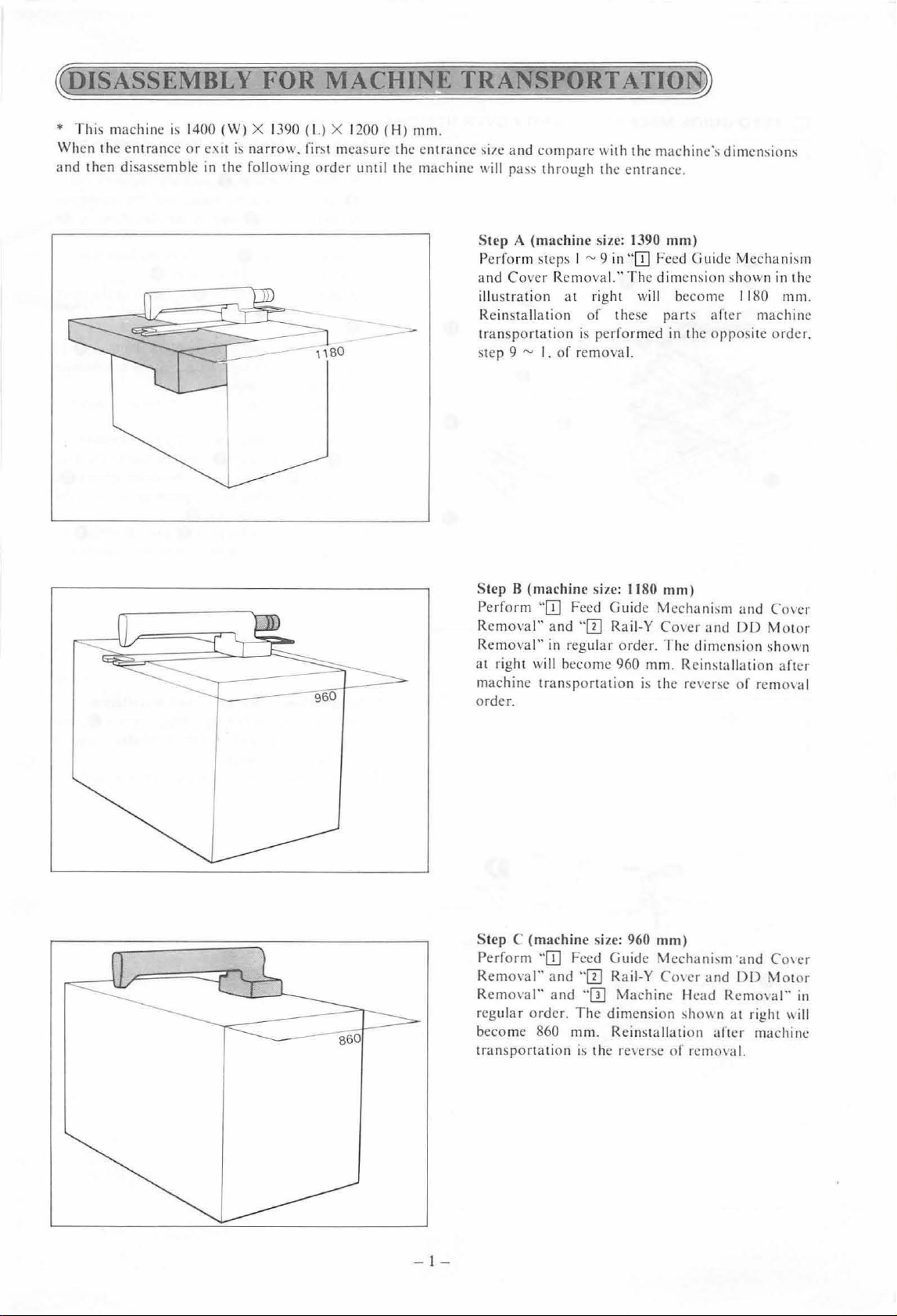
* This machine
Wh
en the entrance or e:w is narrow. fir
and then
di
i
~
14
sas~em
bl c
00 (W) X
in the following order until the machine
1390
(L) X
1200 (H) mm.
l!t
mca~ure
the entrance
- - transportatio n
~itc.:
a
nd
compa re
11
ill
pas~
through the entrance.
St
ep A (machine
Perfo
rm
steps I
and Cover
illustration at right
R
ei
nstallation
step 9
Removal." The dimension shown
"'
I.
of
11ith
size: 1390
"'9
in''ITJ Feed
of
these
is
performed
rem ova
the
machine·~
mm)
Guid
will
become 1180
parb
in the
I.
dimcnsiom
~.:
Mechanism
in the
mm
after machine
opposite orde
.
r.
Step 8 (machine
Perform
Removal"
Removal"
at righ t will become 960 mm . Rein!.taii<Hion aft
machine transportation
o
rder
St
Perform "
Remol'al"
Remo1al" and "
regular order.
become 860 mm. Rcinl!
t
ra
"ITJ
.
ep C (machine
ITJ
nsportation
size:
1180
mm)
Feed Guid e
and "!II Raii-Y Cover and
in
regular order.
size: 960
Feed Guide Mechani,m and Co1cr
and
"!II Raii-Y C01er and
ITJ
The
dimension
i~
the rc1er
Mcchani~m
The
i
~
the re1ersc
mm)
Machine Head Rcm01al"
l!l1011
tallation aft..:r machine
sc
of
rcmo1al.
and Cover
DD
dim ension shown
of
DD
n at right 11i
Mot or
rem01a l
Motor
er
in
ll
- I -
Page 5
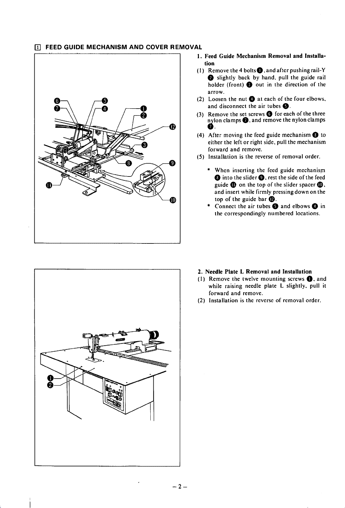
OJ
FEED GUIDE
MECHANISM
AND
COVER
REMOVAL
I.
(I)
(2) Loosen the nut 8
(3) Remove the set screws 0 for each
Feed Guide
tion
Remove the 4
f)
slightly back by
holder
arrow.
and
-~on
(front) 8 out
disconnect the
clamps
Mechanism
boltsO,
hand.
at
air
8.
and
remove the nylon clamps
Removal
and
in
the direction
each
tubes
and
after
pushing rail-Y
pull the guide rail
of
the four elbows,
8.
Installa-
of
the three
of
the
(4) After moving the feed guide mechanism
or
either the left
forward
(5) Installation
and
right side, pull the mechanism
remove.
is
the reverse
of
removal order.
* When inserting the feed guide mechanism
0 into the slider
guide
CD
on
and
insert while firmly pressing
top
of
the guide
*
Connect
the correspondingly
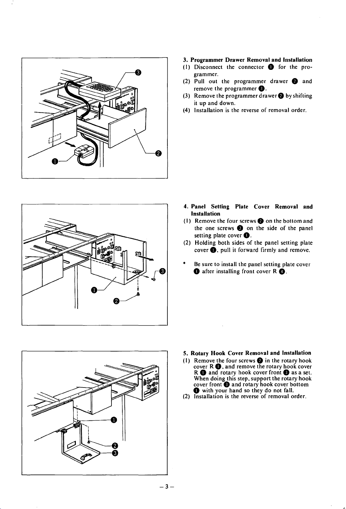
2. Needle
(I)
Remove the twelve
while raising needle plate L slightly, pull it
forward
(2) Installation
the
Plate L Removal
and
is
f),
the
top
bar
air
tubes 8
mounting
remove.
the reverse
rest the side
of
the slider spacer
down
48.
and
elbows 8 in
numbered
and
of
locations.
Installation
screws
removal order.
of
the feed
0.
0 to
4B,
on
the
and
-2-
Page 6
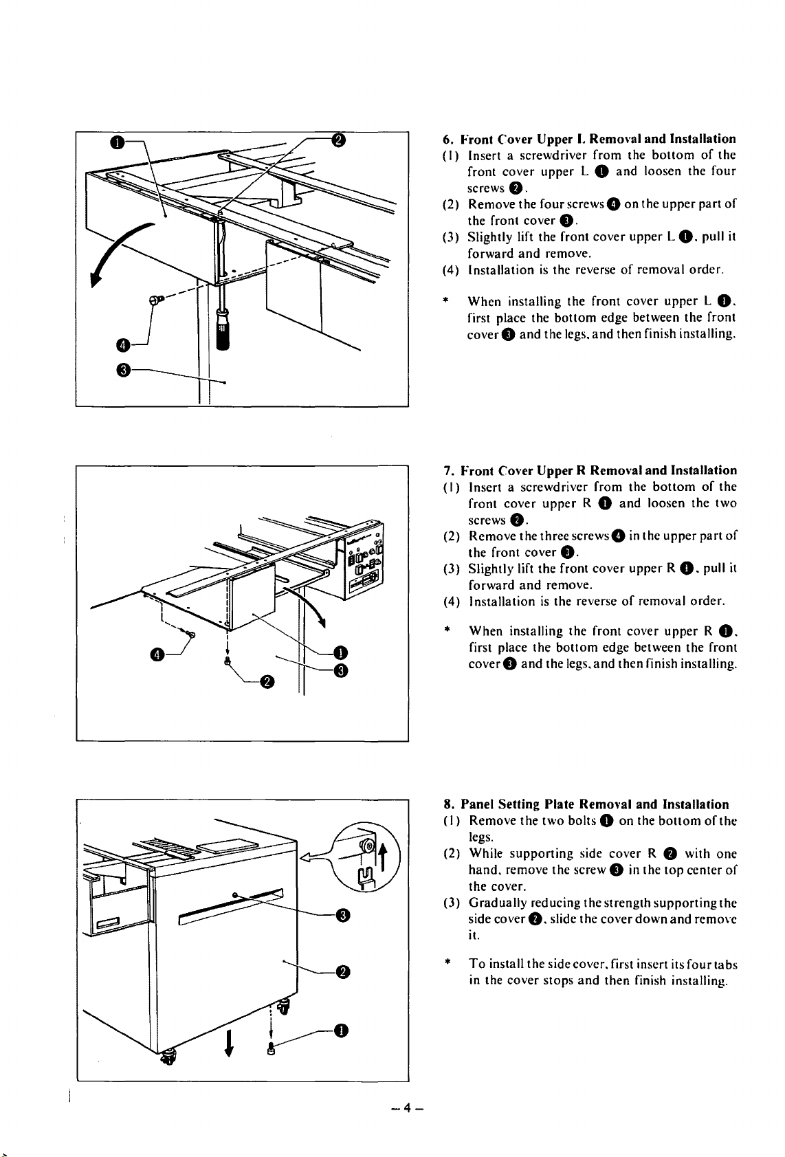
3. Programmer Drawer Removal and Installation
(I)
Disconnect the connector 8 for the pro-
grammer.
(2) Pull
(3) Remove the programmer
(4) Installation
4. Panel Setting Plate Cover Removal and
(I)
(2) Holding both sides
out
the programmer drawer 8 and
remove the programmer
it
up
and
down.
is
the reverse
Installation
Remove the four screws 8 on the bottom and
the one screws
setting plate cover
cover
8.
8 on the side
pull it forward firmly and remove.
8.
drawer8
of
by shifting
removal order.
of
8.
of
the panel setting plate
the panel
Be
sure
to
*
8 after installing front cover R
5. Rotary Hook Cover Removal and Installation
(I)
Remove the four screws 8 in the rotary hook
cover R
8 and rotary hook cover front 8
R
When doing this step,
cover front
8 with your hand so they
(2) Installation
install the panel setting plate cover
8.
8,
and
remove the rotary hook cover
as
bottom
not fall.
8
and
is
the reverse
support
rotary hook cover
the rotary hook
do
of
removal order.
a set.
-3-
Page 7
6. Front ('over Upper
(I)
Insert a screwdriver
front
cover
upper
screws
8.
(2)
Remove
the
(3) Slightly lift the
forward
Installation
(4)
*
When
first place the
cover 0 and
front
installing
the
fourscrews8
cover
and
remove.
is
the reverse
bottom
the legs.
0.
front
I.
Removal
from
L 0
cover
the
front
edge between
and
and
Installation
the
bottom
and
loosen the
on
the
upper
of
removal
cover
then finish installing.
upper
L
0.
upper
the
of
four
part
pull it
order.
L
front
the
of
0.
7. Front Cover Upper R Remm·al
(I)
Insert a
front
screws
(2)
Remove
the
(3)
Slightly
forward
Installation
(4)
When
*
first place
coverO
screwdriver
cover
upper
8.
the
three
front
cover
lift the front
and
is the reverse
installing the
the
and
R 0
screws8
0.
remove.
bottom
the legs.
from
cover
front
edge between
and
and
Installation
the
bottom
and
loosen the
in the
upper
of
removal
cover
then finish installing.
upper
R
0.
upper
the
of
two
part
pull it
order.
R O.
front
the
8. Panel Setting Plate Removal and Installation
(I)
Remove
legs.
(2) While
hand.
the
(3)
Gradually
side
it.
the
supporting
remove
cover.
cover
8.
two
bolts 0
the
screw 0 in the
reducing
slide the
side
the
on
cover
strength
cover
the
bottom
R 8 with
top
supporting
down
and
of
one
center
remO\·e
the
the
of
of
To
*
install
in the
-4-
the
cover
side
stops
cover.
and
first insert its
then
finish installing.
four
tabs
Page 8
(4) Disconnect floppy
harne
!>~
B 0 from the floppy
the two
plate
(5)
Di!>eon
0.
{6)
Loosen the four screw:-
setting plate
(7)
l
mtallation
harnessc~
f)
.
nect the barne
and
pull it inside the panel setting plate
f)
forward and remove.
is
the reverse
harne!>s
out from the panel
A 0
and flop
dri,
·e 0 . and pull
s:-
0 to the switch panel
~.
pull the panel
of
removal order.
py
~etting
f)
.
When installing.
*
connectors firml
9. Needle Pl
Installation
(I) While holding need
remove th e eight bolts to needle plate support
guide brackets A
needle plate
To
(2)
~upport
e. I ex
p. 2). firmly tighten the eight bolts
in
stalling the
ate
pl
ate
install. temporarily install needle plate
guide bracket A e with the eight
t.
after installing needle plate
L.
be
~urc
to plug in all
y.
Support Guide Remo\'al and
le
plate support guidc A 0 .
e.
and
then remo
suppor
t guide
support
as
a single unit.
guides. remove needle
ve
bolt~
L(refer
e.
Af
the
to
ter
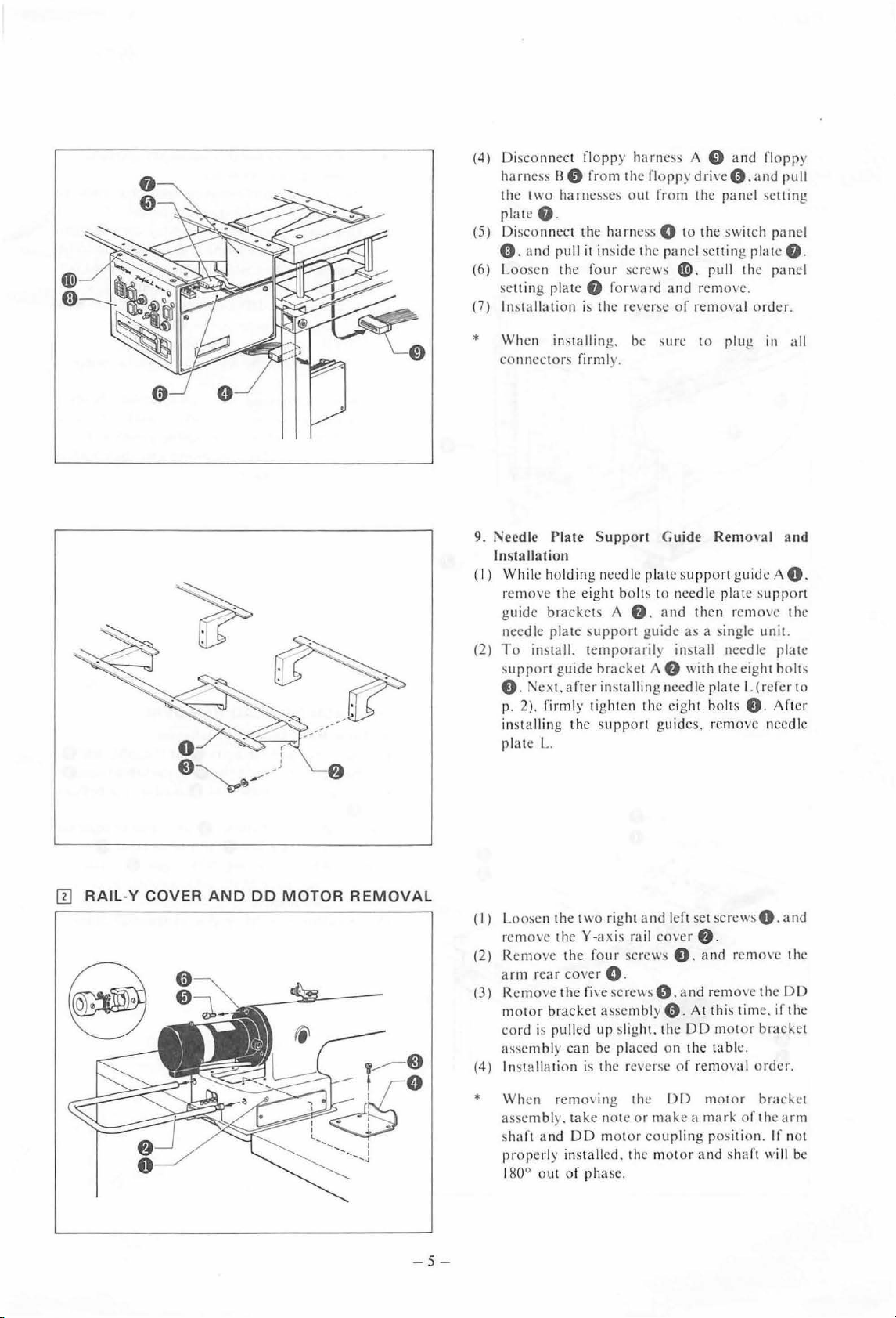
ITJ
RAlL-Y COVER AND DO MOTOR REMOVAL
(I) Loo!>e
(2) Remove the four screws e. and rcmO\C the
{3)
(4) Installation
*
n the two right a nd left set
remove
arm
Remo
motor
cord
as~embly
When
assembly. take note
shaft
prope
180° out
theY
rear cover 0 .
ve
the five
bracket assembly
is
pulled up slight. t
can
rcmo'
and
rl
y installed. the mot
of
-5-
-axis rail cover e.
serew!>
O . and
0.
he
be placed on the tabl
is
the
rC\Cr~e
ing the
DD motor
phase.
()()
or
make a mark
coupling posi ti on. If not
sen:wsO.and
remo\e
At this time. if the
DD
of
removal order.
motor
or
and shaft will
the
motor bracket
e.
brad.et
of
the arm
DO
be
Page 9
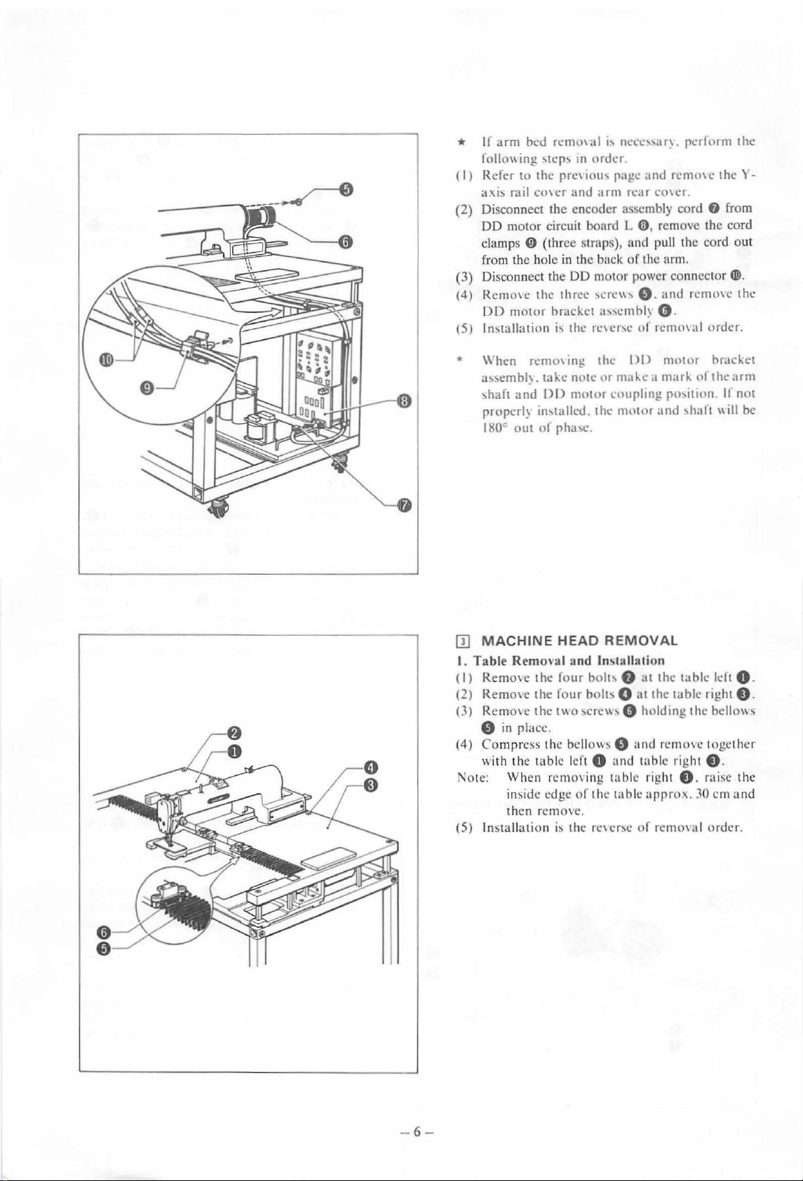
II
arm
bed
*
foliO\\
(I)
Refer
a:-.is rail
Disconnect
(2)
DO motor
clamps
from the hole in the back
Disco
(3)
(4)
R
emo\e
DO
motor
ln::.tallati
(5)
remm
ing
\tep~
to
the
pre\iou'
co\cr
the encoder
circuit
0
(three strap
nnect th e DO m
the three
bracket
on
i'
a I "
neee,,a
Ill
order
.
page
and
arm
rear
assembly
board
L 0 , remove the cord
s), and pull the cord
of
oto
r power
'ere"'
0 .
a"embh
the
re\er'c
ot
r~.
and
rernme
co\er.
cord
the arm.
connector(@.
and
()
.
rcmmal
pert
orm
0 from
remme
order.
1 he
theY-
out
the
\\'hen
•
a!>~embl~.
-,haft
proper!~
J8Q
IIJ
MACHINE
I. Table
(
I)
Remo\c
(2)
Remo\e
(3) RemO\ e
0
Co
(4)
with the t
1
0te:
(5) I
rcmO\ tng
and
C
OUt
Remo,·al and ln!>
in
place.
mp
ress the bellows 0
Wh
en rern
in
side
then
nstallation
take
note
DD
motor
in\talled.
of
pha\C .
HEAD
the
four
the
four
the
t\\0
able
left 0
o\
edge
of the table
remove.
is
the r
the
I)
I)
motor
ur
m.tke a mark
coupling
the
nwtor
po,tlton. If
and
REMOVAL
tallation
bolt' 8 at
bolt-. 0
sere\\\ e holding
and
ing
table
c,crsc
the
at
the
table
and
remove together
table right 0 .
right 0 . ra ise
approx
of
rcmoHtl
uf
'halt
table
the
.
.10
brJckct
the
arm
not
"'II
be
left 0 .
right 0 .
bellO\\!>
th
e
em
and
order.
-6-
Page 10
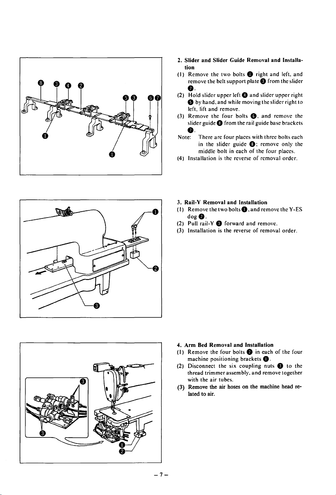
2.
Slider
and
Slider
tion
(I ) Remove the
remove the belt
••
(2) Hold slider
e by
hand.
left. lift
(3)
Remove the
slider
••
Note:
(4)
Installation
and
guideO
There
arc
in the slider guide
middle bolt
Guide
Remm·al
two
bolts 0 right
support
upper
and
while moving the slider right to
remove.
four
from the rail guide base brackets
four
plate e from the slider
left G
and
bolts
8.
places with three bolts each
0:
in
each
of
is
the reverse
of
and
Installa-
and
left.
slider
upper
and
remove the
remove only the
the four places.
removal
order.
and
right
3. Raii-Y
(I)
(2) Pull rail-Y 8 forward
(3)
4.
Arm
(I)
(2) Disconnect the six
(3) Remove the air hoses
Removal
Remove the
dog
f).
Installation
Bed
Remove
machine positioning brackets
trimmer
thread
with the
lated
to
air.
and
two
is
the reverse
Removal
the
four
assembly.
air
tubes.
Installation
boltsO.and
and
bolts
coupling
remove
and
remove.
of
removal
Installation
f)
in
each
theY
of
0.
nuts 8
and
remove together
on
the machine head re-
-ES
order.
the four
to
the
-7-
Page 11
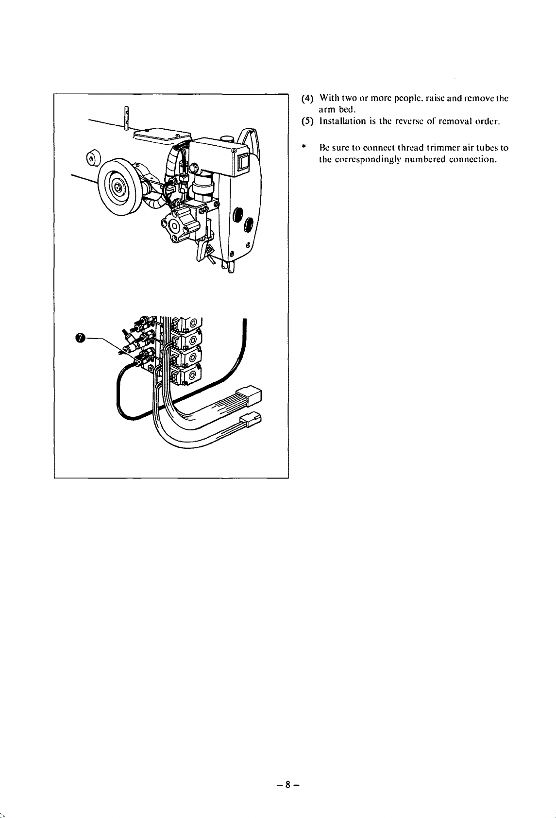
(4) With two
arm
(5) Installation
*
Be
the correspondingly numbered connection.
or
more people. raise
bed.
is
the reverse
sure to connect thread trimmer
and
of
removal order.
remove the
air
tubes to
-8-
Page 12
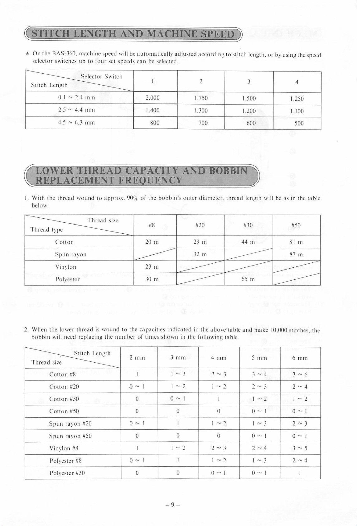
~STITCH
*
On
the HAS-360. machine
selector switches
LENGTH
sreed will be automatically
ur
10
four set
AND
~reeds
can
MACHINE
adju~ted
be
selected.
SPEED~
according to stitch length. or by using the
sreed
s
~
0.1 ~ 2.4
2.5 ~ 4.4
4.5
LOWER
mrn
mm
~I'
d
mm
THREAD
REPLACEMENT
I.
With t
he
thread wou nd
be
low.
~
.
Col! on
Srun
rayon
to
appr
2.000
1.400
800
CAPACIT
FRE
ox.
90
UENCY
~[
of
the
#8
20
I
bobbin\
m
2
1.750
1.300
700
AND
outer diameter. thread length will
BOBBIN
#20
29
111
32
m
3
1.500
1.200
600
11
30
44 m
4
1.250
1.
100
500
be
as in the table
#50
81
m
87
m
Yinylon
Polyester
2.
When the lower thread
bobbin
~
will need
e
Col!on #8
Couon
Couon
Couon
Sru
Srun rayo n #50 0
Yinylon
#20
#30 0
#50 0 0 0
n rayon #20
#8
rer
lacing the
23m
-----------
30
111
is
wound to the caracities ind icated
number
of
tim
e~
shown in the following table.
2 mm
I
o
~
I
o
~
I I I
I
3 mrn
t~3
t~2
o
~
0
~2
I
~
---------
~
65
---------
in
the
abo
\C
table and make 10.000
4 mm 5
2 ~ 3
~2
I
I I
~2
0
2
"'
3
m
111111
3~4
2
~
3
1
~2
o~
t
~3
o~t
2"-' 4
----------
=----------
s
titchc
~.
the
6
111111
3~6
2~4
t
~2
t
o~t
2 ~ 3
o~t
3
"'
5
Polyest
er
#8
Polyester #30
0"'1
0 0
I 1 "-'2 1 "-'3
"-'
1
0
- 9 -
0"-'
2 ~ 4
1
I
Page 13
~MECHANICAL
OJ
NEEDLE
BAR.
THREAD
DE§CRIPTIONS
TAKE-UP
LEVER. LOWER
))
SHAFT.
AND
ROTARY
HOOK
MECHANISM
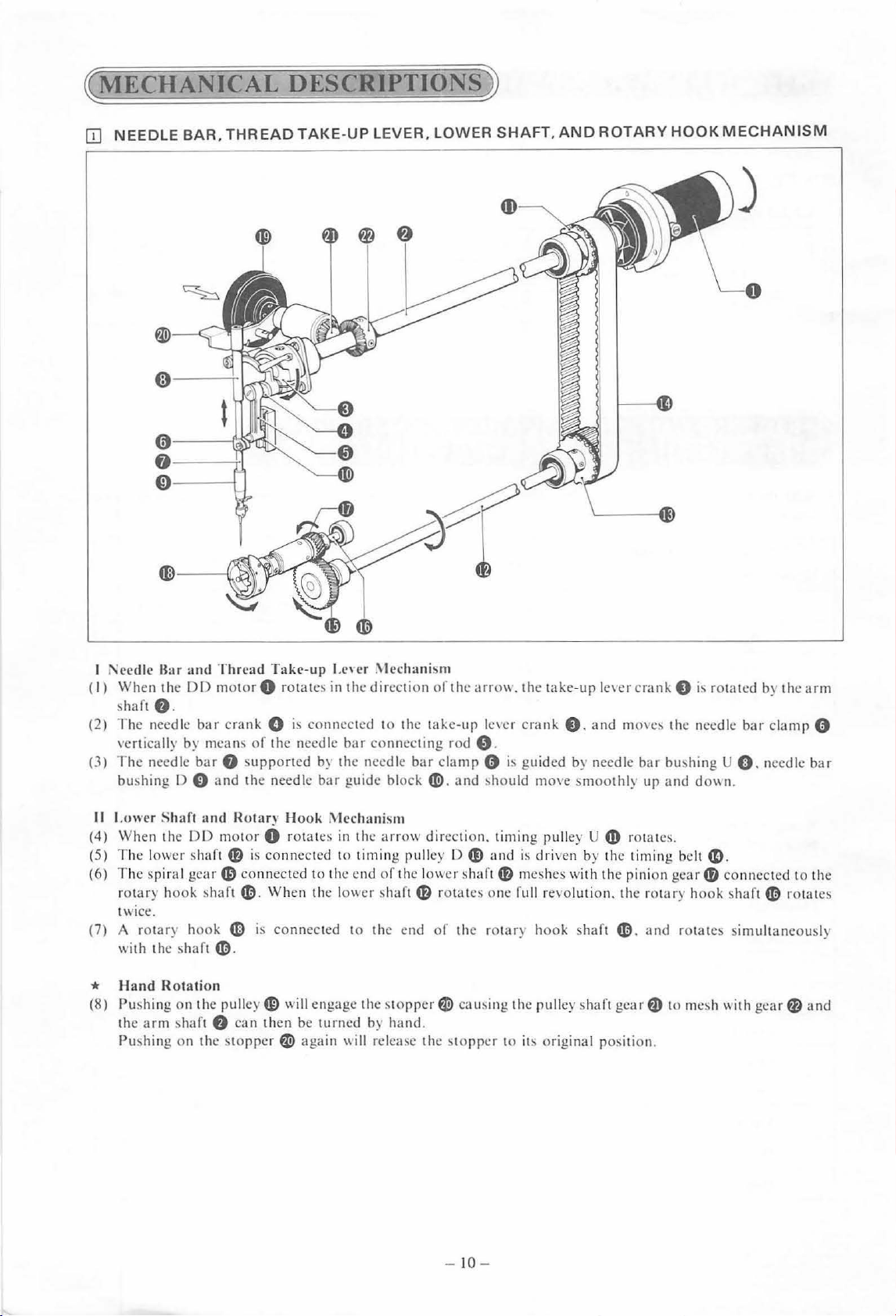
I Needle
(I ) When the
(2)
(3)
II
(4)
(5)
(6)
{7)
*
(8)
Bar
and
Thread Take-up
DO
motor
shaft e.
The nee
vertically by mea ns
The needle
bw.hing [) 0 and the needle
Lower
When the
The lower shaft
The sp iral gear
rotary hook
twice.
A rot
with
Hand
Pushing
the a rm
Pushing
dle.:
bar
bar
Shaft
DD
ary
hook
the shaft
Rotation
on
the pulley
~ha
ft
on the
cr
ank 0
f)
sup
and
Hotary
motor
4B
(0
connected to the end
shaft~-
4D
~
-
8
can
stoppe
I.e'
cr .\lechanism
0 rotates in t
is
of
the needle
ported by the needle
Hook
0 rotates
is co nnected to timin
When the lower shaft
is connected to the end of the rotar) hook shaft
G)
will engage the
then be turned by hand.
r~
again
he
direction
connected to the take
bar
connecting rod e.
bar
guide
~lcchanism
in
the
arrow
of
stopper~
"ill
release the
of
bar
clamp 0
block~-
direction . timing pulley U
g pul
ley
the lower shaft
4B
rotates one full revolution . the
the
arro\\.
-up
and
D (I) and
causing the pulley shaft
stopper
the take-up len:r
le\er
crank
0.
is
guided by needle
~hould
move
smoothly
is
driven by the timing be
4B
meshes with the pinion gea r
to
it!.
original position.
and
4D
4D.
gear
crank
0
i~
rotated by the
mo\e~
the need
bar
bushing U 0 . needle
up and dO\\n.
rotates.
lt
a.
4D
rotar
y hook
and
rotates simultaneously
f)
to me!>h \\ith
arm
le
bar
clamp 0
bar
.
connected to the
s
haft~
ro tates
gearfl)
and
-10-
Page 14
[I]
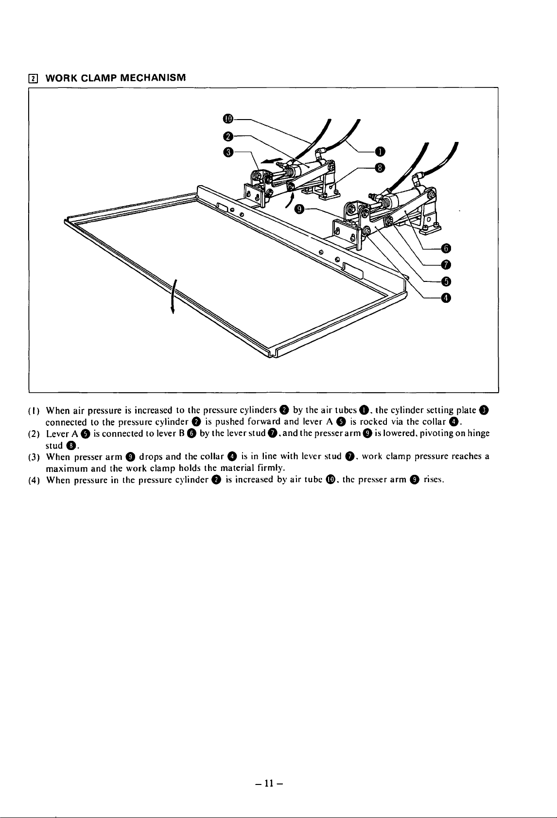
WORK CLAMP
MECHANISM
(I)
When
air
pressure
connected
(2) Lever A 8
stud
(3)
When
maximum
(4) When pressure in the pressure cylinder 8
to
is
e.
presser
and
is
increased
the pressure cylinder 8
connected
arm 0 drops
the
to
work
to
the pressure cylinders 8 by the
lever B 8 by the lever
and
the
clamp
holds the material firmly.
is
collar G is
pushed
is
increased by
forward
stud
in
and
lever A 8
f).
and
the presser
line with lever stud
air
tube
air
tubes
0.
is
rocked via the
arm 0 is
f).
work
O. the presser
the
cylinder setting plate 8
collar
G.
lowered. pivoting
clamp
pressure reaches a
arm
0 rises.
on
hinge
-11-
Page 15
IIJ
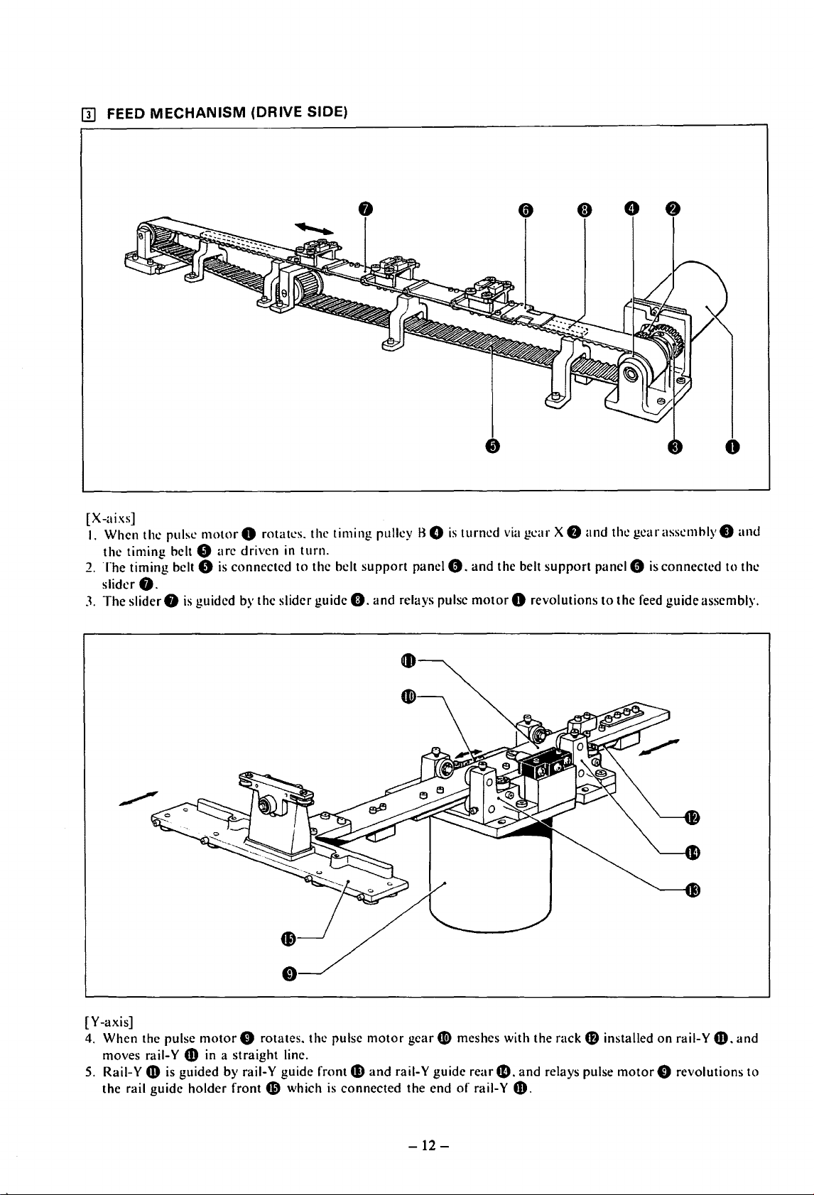
FEED
[X-aixs]
1.
When the pulse
the timing belt e
2.
The
slider
3.
The
MECHANISM
timing belt 8
8.
slider 8
(DRIVE SIDE)
motor
0 rotat..:s. the timing pulley H 0
arc
driven
is
connected to the belt
is
guided by the slider guide G.
in
turn.
support
and
is
panel
0.
relays pulse
turned
and
motor
via
g..:ar X 8
the belt
support
0 revolutions
and
the
gear
assemhly 8
panel 0
to
is
connected to the
the feed guide assembly.
and
[Y-axis]
motor
4. When the pulse
moves rail-Y $ in a straight line.
5.
Rail-Y
the rail guide holder front 6' which
4D
is guided by raii-Y guide front
0 rotates. the pulse
motor
gear
4»
and
rail-Y guide
is
connected the end
G)
meshes with the rack 8 installed
readD.
of
rail- Y
$.
-12-
and
relays pulse
motor
on
rail- Y
f)
revolutions
$.and
to
Page 16
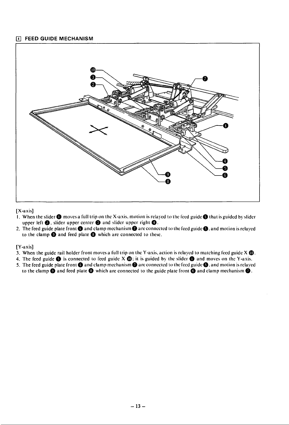
[I]
FEED
GUIDE
MECHANISM
[X-axis]
I. When the
upper
2.
The
to the
[Y-axis]
3. When the guide rail holder front
4.
The
The
5.
to the
sliderO
left
8.
feed guide plate front 0
clamp
feed guide 0
feed guide plate front 0
clamp
slider
f)
f)
and
and
moves a full
upper
feed plate 0 which
is
connected
feed plate 0 which
center 0 and
and
and
trip
on
the X-a.xis.
slider
clamp
mechanism
arc
mm·es a full trip
to
feed guide X
clamp
mechanism
arc
connected
motion
upper
f)
arcconneetcd
connected
on
theY
41>:
it
f)
arc
is
relayed
right
0.
to
these.
-a
.xis.
is
guided by the slider 0
connected
to
the guide plate front 0
to
to
action
to
the feed
the feed
is
relayed
the feed
guideO
guide8.and
guideO.
to
matching
and
and
that
mo,·es
clamp
is
guided by slider
motion
feed guide X
on
the Y -axis.
and
motion
mechanism
is
relayed
is
relayed
41).
0.
-13-
Page 17
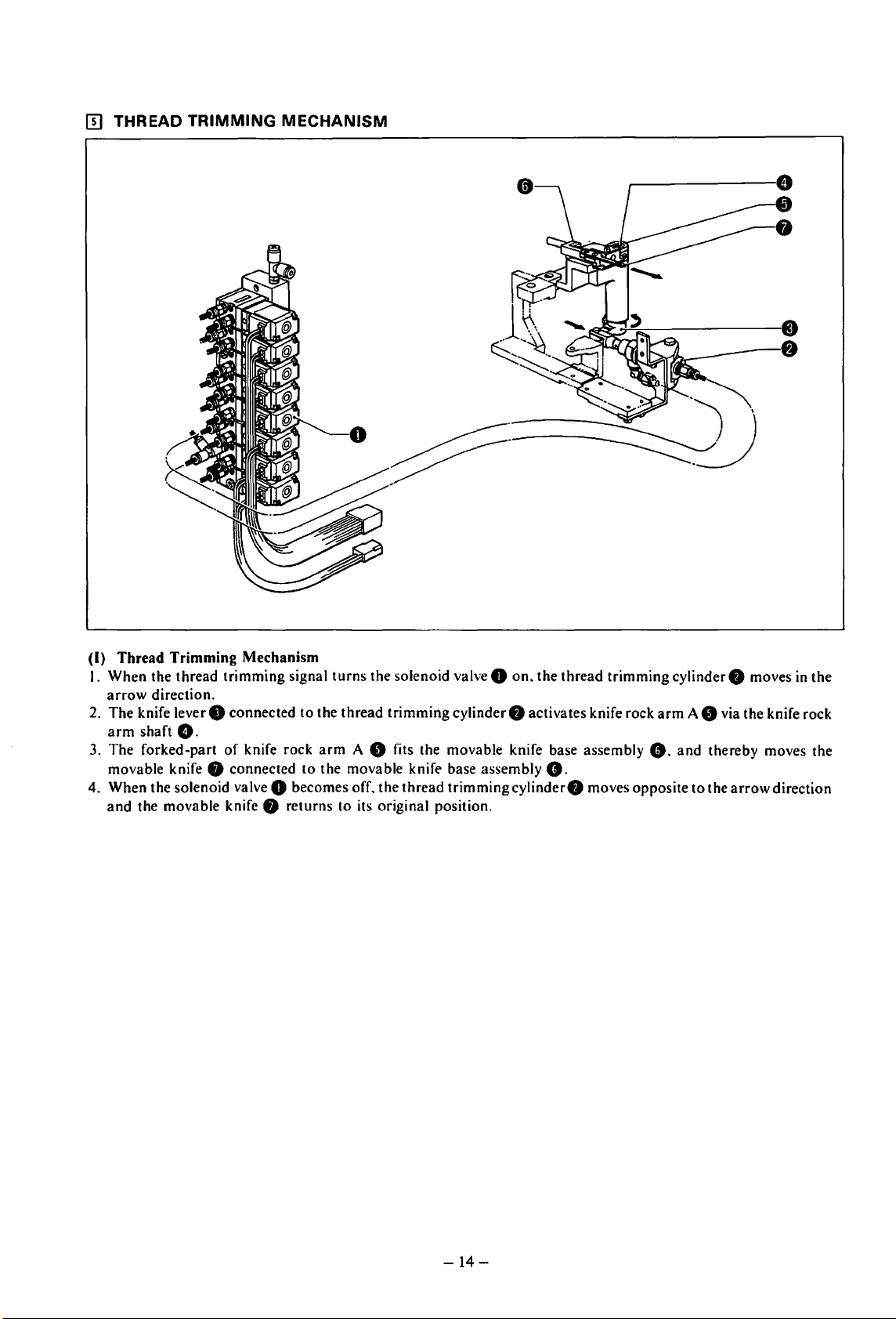
IT]
THREAD
TRIMMING
MECHANISM
(I)
Thread
I.
When
arrow
The
2.
arm
3.
The
movable knife
4. When the solenoid valve 0 becomes off. the
and
Trimming
the thread
direction.
knife lever 8 connected
shaft
G.
forked-part
the movable knife 8 returns
Mechanism
trimming
of
knife rock
8 connected
signal
to
the
arm
to
the movable knife base assembly
turns
the solenoid valve 0
thread
trimming
A 8 fits the movable knife base assembly
to
its original position.
thread
on.
the
thread
trimming
cylinder 8 activates knife rock
8.
trimming
cylinder8
moves opposite
cylinder 8 moves in
arm
A 8 via the knife rock
8.
and
thereby moves the
to
the
arrow
the
direction
-14-
Page 18
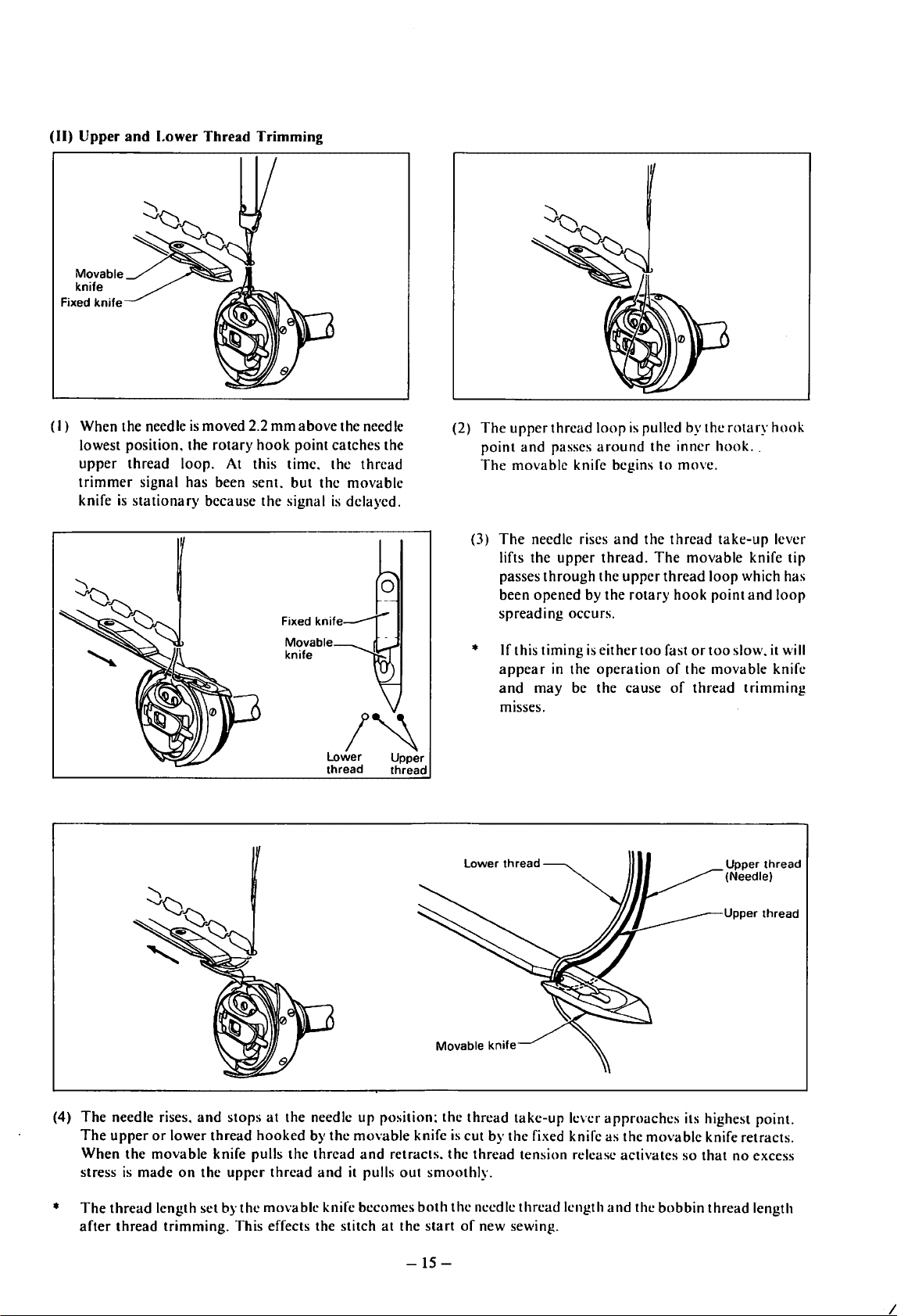
(II)
Upper
and
(I)
When the needle
lowest position. the
upper
trimmer
knife
thread
is
stationary
Lower
signal has been sent.
Thread
is
moved 2.2
loop. At this time. the
because
rotary
Trimming
mm
hook
the
above
point
but
signal
the needle
catches the
thread
the
movable
is
delayed.
(2)
The
point
The
The
(3)
been opened by
spreading
upper
thread
loop
and
passes
around
movable knife begins
needle rises
lifts the
passes
upper
through
and
thread.
the
the
occurs.
is
pulled by the
the
inner
to
the
thread
The
upper
thread
rotary
hook
move.
movable
loop
point
rotary
hook
..
take-up
knife tip
which has
and
hook
lever
loop
Movable
knife
•
Lower
Movable
If this timing
appear
and
m1sses.
thread
knife
in
may be the cause
is
the
operation
either
too
fast
of
of
or
the
thread
too
slow. it will
movable knife
trimming
(4)
The
*
needle rises.
The
upper
When
stress
The
thread
after
the
is
made
thread
and
stops
at
the needle up position; the
or
lower thread
movable
on
the
length set by the movable knife becomes
trimming.
hooked
knife pulls
upper
This effects the stitch
the
thread
by
thread
and
the
it pulls
movable
and
retracts.
at
knife
out
smoothly.
both
the
start
thread
is
cut by
the
thread
the
needle
of
new sewing.
take-up
the
fixed knife as the
tension release activates
thread
length
-15-
lever
approaches
movable
and
the
bobbin
its highest
knife retracts.
so
that
no
thread length
point.
excess
I
Page 19
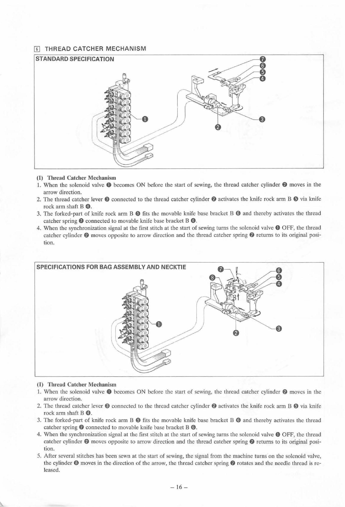
[II
THREAD
CATCHER
MECHANISM
STANDARD SPECIFICATION
(I)
Thread Catcher Mechanism
L.
When the solenoid valve 0 becomes
ON
before the start
arrow direction.
2.
The
thread catcher
rock arm shaft B
3.
The forked-part
catcher spring
4.
When the synchronization signal at the first stitch at the start
catcher cylinder
lever@
connected to the thread catcher cylind
0.
of
knife rock arm B 0
8
co
nnected to movable knife base bracket B 0 .
f)
moves opposite
fits th
e movable knife base brack
to
arrow direction and the thread catcher spring
tion.
of
sewing,
of
the thread catcher cylinder
er
f}
activates the knife rock arm B 0 via knife
et
B 0 and th ereby activates the thread
sewing turns the solenoid valve 0
f)
f}
moves
in the
OFF
, the thread
returns to its original posi-
SPECIFICATIONS
(I)
Thread Catc
1.
When the solenoid valve 0 becomes
FOR
her
Mechanism
BAG ASSEMBLY AND NECKTIE
ON
before the start
of
sewin
g,
the thread catcher cylinder
arrow direction.
The
2.
thread catcher lever ~ connected to the thread catcher cylinder
rock arm shaft B
3.
The
forked-part of knife rock arm B 0 fits the mo vab le knife base bracket B 0 and thereby activates the thread
catcher spring
0.
8 connected to movable knife base bracket B
0.
f)
activates the knife rock arm B 0 via knife
4. When the synchronization signal at the first stitch at the start of sewing turns the solenoid valv
catcher
cylinder
f}
moves
oppo
site to arrow direction and the thread catcher spring
f)
returns to its original posi-
tion.
d1
e start
of
5. After several stitches has been sewn at
cy
linder
(j)
mo
the
ves in the direction
of
the arro
sewing, the signal from the machine turns on the solenoid valve,
w,
the thread catcher spring
f)
rotates and the needle thread is re-
leased.
f)
moves
in
the
e 0 OFF, the thread
-16-
Page 20
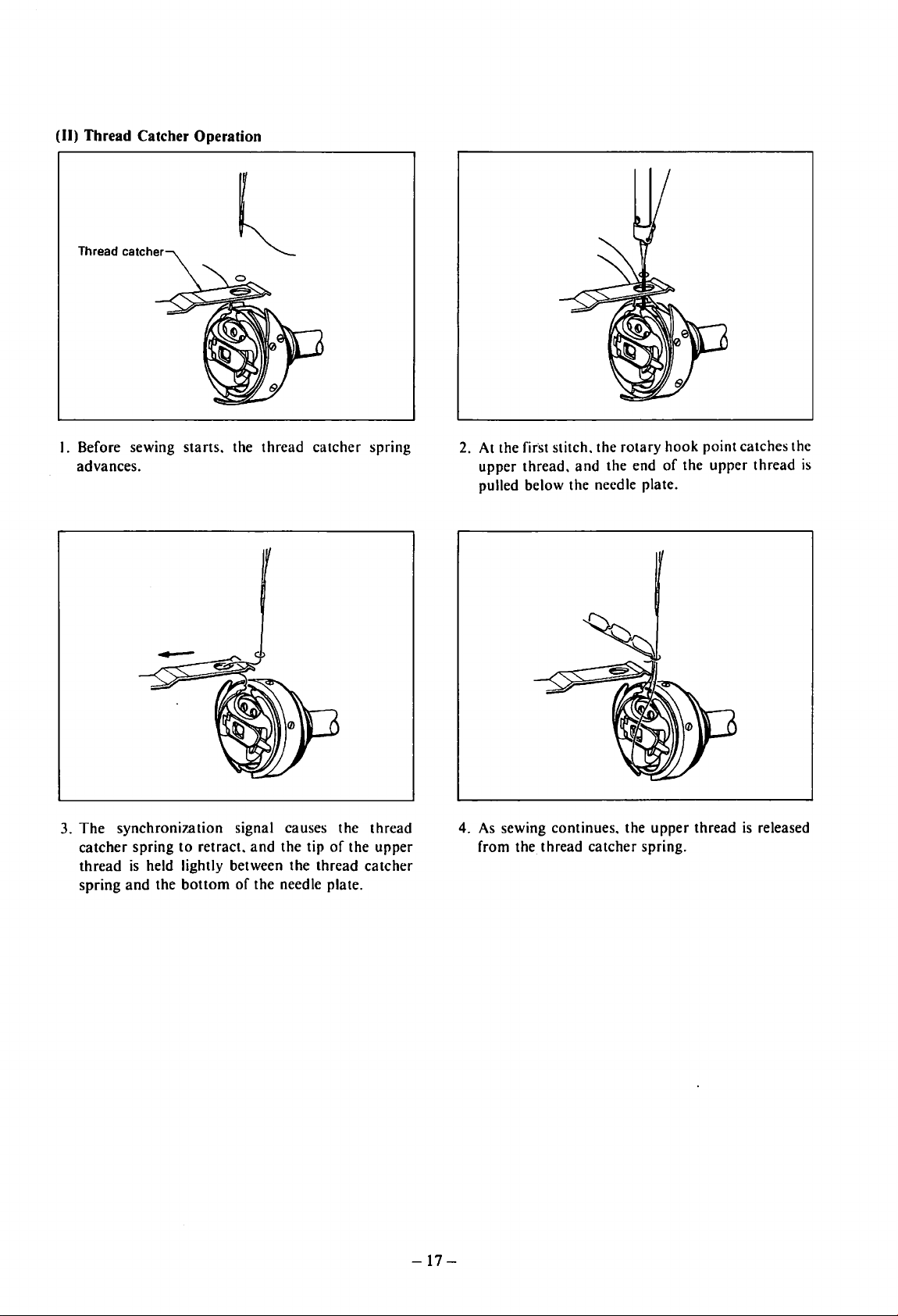
(II) Thread Catcher Operation
Thread catcher
I. Before sewing starts. the thread catcher spring
advances.
2.
At the first stitch. the rotary hook point catches the
upper thread.
pulled below the needle plate.
and
the end
of
the upper thread
is
The
3.
catcher
thread
spring
synchronization signal causes the thread
spring
to
retract.
is
held lightly between the thread catcher
and
the
bottom
and
the tip
of
the needle plate.
of
the upper
-17-
4.
As
sewing continues. the upper thread
from the thread catcher spring.
is
released
Page 21
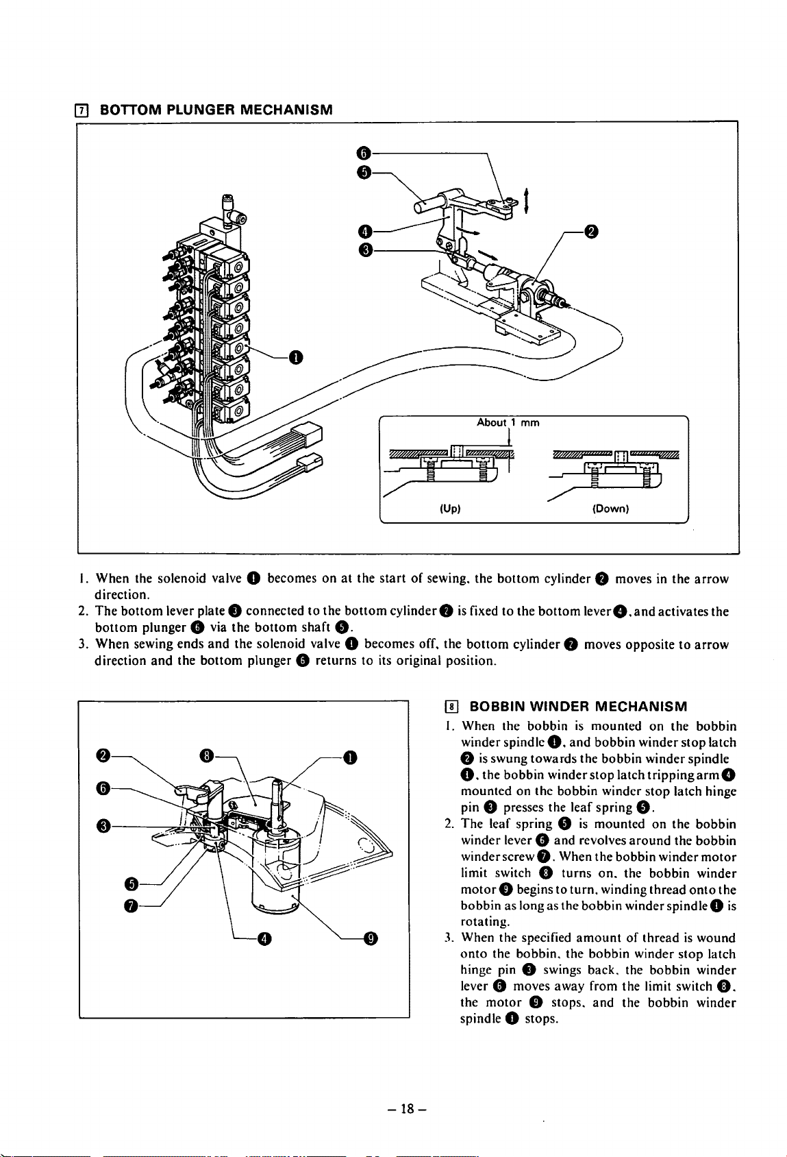
[!]
BOTTOM PLUNGER
MECHANISM
;?f8if'
(Up) (Down)
I. When the solenoid valve 0 becomes
direction.
2.
The
bottom
bottom
3. When sewing ends
direction
lever plate 8 connected
plunger 8 via the
and
the solenoid valve 0 becomes off. the
and
the
bottom
plunger 8 returns to its original position.
bottom
shaft
to
on
the
at
bottom
8.
the
start
of
cylinder8
sewing. the
[I)
I. When the bobbin
bottom
is fixed to the
bottom
BOBBIN
winder spindle
8
is
swung towards the bobbin winder spindle
cylinder 8 moves in the
bottom
cylinder 8 moves opposite
WINDER
0.
and
leverG.and
is
O. the bobbin winder
mounted on the bobbin winder
pin
8 presses the leaf spring
2.
The leaf spring 8
winder lever
winder screw
limit switch 0 turns
motor
bobbin as long as the bobbin winder
rotating.
3.
When the specified
onto
the bobbin. the bobbin winder
hinge pin
lever
8 moves away from the limit switch
the
motor
spindle
8
8.
0 begins to
0 swings back. the bobbin winder
0 stops.
0 stops.
is
and
revolves
When the bobbin winder
turn.
amount
activates the
MECHANISM
mounted
bobbin
stop
on
winder
latch
trippingarmG
stop
8.
mounted
on.
winding thread
and
on
around
the bobbin winder
of
thread
the bobbin winder
arrow
to
arrow
the bobbin
stop
latch
latch hinge
the bobbin
the bobbin
motor
onto
the
spindleO
is
wound
stop
latch
0.
is
-18-
Page 22
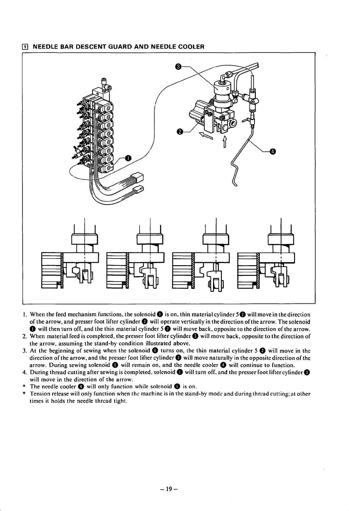
IT]
NEEDLE BAR
DESCENT
GUARD
AND
NEEDLE COOLER
I. When the feed mechanism functions. the solenoid 0 is on. thin material cylinder
of
the
arrow,
0 will
2.
When material feed
the
arrow.
3. At the beginning
direction
arrow.
4.
During
will move
*
The
needle cooler 8 will only function while solenoid 0
* Tension release will only function when the machine
times
it
and
presser foot lifter cylinder 0 will
then
turn
off.
and
the thin material cylinder
is
completed. the presser foot lifter cylinder 0 will move back. opposite
assuming
of
the
During sewing solenoid 0 will remain on.
thread cutting after sewing
in
the direction
holds the needle thread tight.
the
stand-by
of
sewing when the solenoid 0
arrow.
and
the presser foot lifter cylinder 0 will move naturally
of
condition illustrated above.
is
completed. solenoid 0 will
the
arrow.
operate
58
turns
and
vertically
will move back. opposite
on,
the thin material cylinder
the
needle cooler 8 will continue
is
is
in
the stand-by mode
on.
turn
in
off. and
the direction
the
and
-19-
58
will move in the direction
of
the
arrow.
The
to
the direction
58
in
the
opposite direction
presser foot
during
thread cutting;
of
to
the direction
will move in the
to
function.
liftercylinderO
solenoid
the arrow.
of
of
the
at
other
Page 23
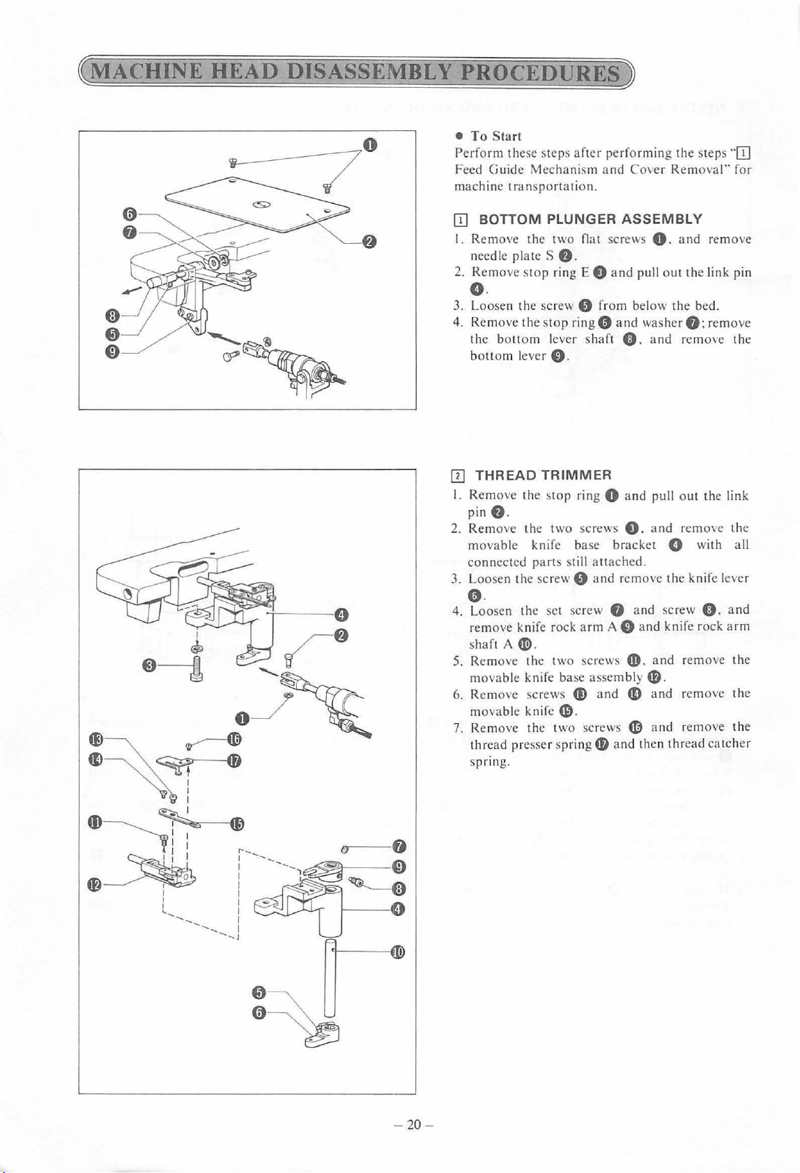
~MACHINE
(;)
HEAD
0
0
DISASSEMBLY
PROCEDURES)
•
To
S
tar
t
Perform these steps aft
Feed Guide Mechanism a
machine tran sportation.
OJ
BOTTOM PLUNGER
I. Remove the two flat screws
needle
2.
Remo
plates
ve
sto
p ring E 8
e.
er
performing the steps
nd
ASSEMBLY
and
e.
3. Loo
se
n the screw 8 from
0
4. Remove the stop ring
the bottom lever shaft
bott om lever
IT]
THREAD
I.
Remove the st
e.
pin
2. Remo
3. Loosen
ve
movable
connected parts still attached.
C).
TRIMMER
op
the t
wo
knife
th
e screw 8 and remove the knife lever
and
0.
ring 0 and pull out the link
screws
base bracket G with all
8.
o.
4.
Loosen the set
remove knife rock
sha
ft
A~-
5.
Remo
ve
the two screws
movable knife base assem bly
6. Remove screws
movable knife
7. Remove the two screws
thread presser spring
s
pnn
g.
sc
rew 8 and screw
arm
A 0
4D.
fD
and
4D
G).
4D
4D
and then thr
"OJ
Cover Removal" for
0.
and
remove
pull out the link pin
be
low the bed.
washer
an
8;
remove
and remove the
and remove the
0.
and
d knife rock
and
remo
ve
arm
the
f».
and remove the
an
d remove the
ead catch
er
-20
-
Page 24
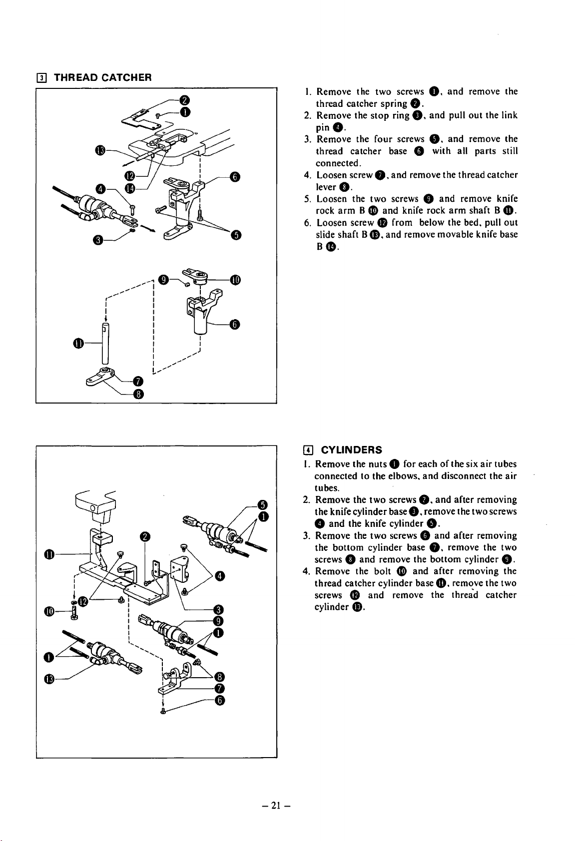
[l]
THREAD CATCHER
I. Remove the two screws O.
thread catcher spring
2.
Remove the
pinG.
3.
Remove the four screws
thread
connected.
4.
Loosen screw
G.
lever
5.
Loosen the two screws 0
rock
arm
6.
Loosen screw 8 from below the bed. pull
slide shaft 8
8
•.
stop
catcher
0.
8 0
48.
8.
ring
8.
base 8 with all parts still
and
remove the thread catcher
and
knife rock
and
remove movable knife base
and
8.
and
and
pull
out
and
remove knife
arm
remove the
the link
remove the
shaft 8
4D.
out
11]
CYLINDERS
I. Remove the nuts 0 for each
connected to the elbows.
tubes.
2.
Remove the
the knife cylinder base
8
and
3. Remove the
the
bottom
screws
4. Remove the bolt 0
thread catcher cylinder base
screws
cylinder
two
screws
the knife cylinder
two
screws 8
cylinder base
0
and
remove the
8
and
remove the threa'd
48.
and
8.
8.
remove the two screws
8.
and
of
the six
air
tubes
disconnect the
and
after removing
and
after removing
0.
remove the two
bottom
after removing the
cylinder
49.
remove the two
0.
catcher
air
-21-
Page 25
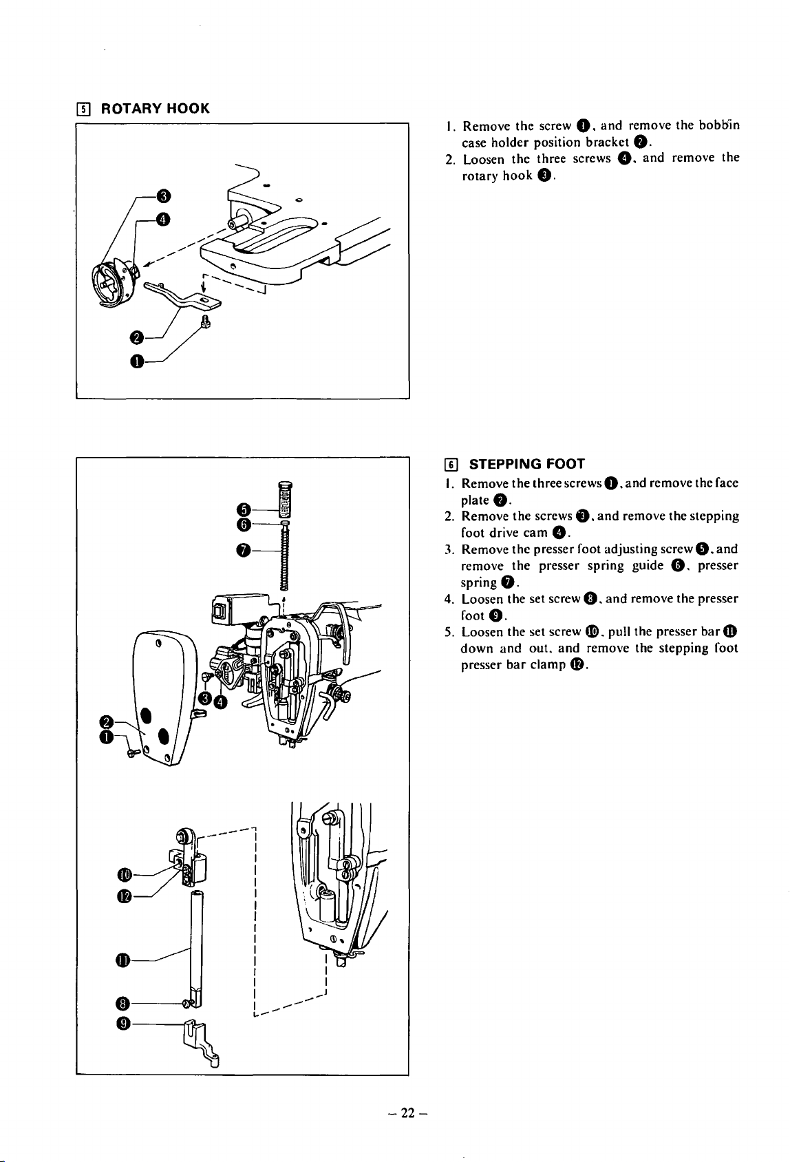
rn
ROTARY
HOOK
I. Remove the screw
case holder position bracket
2.
Loosen the three screws
rotary
!I]
I.
Remove the three screws
plate
2.
Remove the screws O.
foot drive
3.
Remove the presser foot adjusting
remove the presser spring guide G. presser
spring
4.
Loosen the set screw
foot
5.
Loosen the set screw
down
presser
hook
STEPPING FOOT
8.
cam
8.
O.
and
out.
bar
clamp
0.
0.
and
remove the bobliin
8.
8.
and
0.
and remove the face
and
remove the stepping
8.
screwO.
0.
and
remove the presser
41!).
pull the presser
and
remove the stepping foot
f).
remove the
and
badD
-~----~
48
:
I
I
I
I
I
I
I
I
1
...
-~
----
----
--
-22-
Page 26
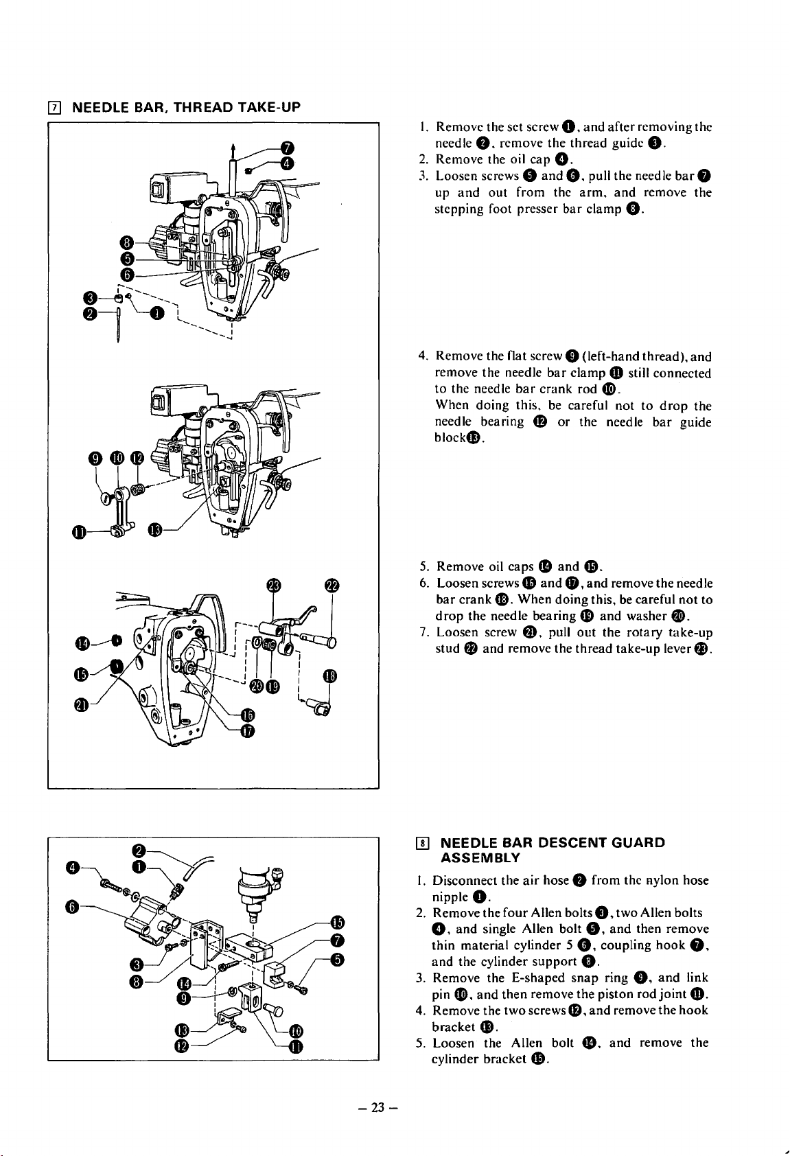
12]
NEEDLE BAR, THREAD TAKE-UP
I.
Remove the set screw
needle
8.
remove the thread guide
2.
Remove the oil
3.
Loosen screws 0
up
and
out
from the
stepping foot presser
4.
Remove the flat screw 0 (left-hand thread), and
remove the needle
to the needle
When doing this. be careful not
needle bearing
block$.
bar
0.
capO.
and
0.
bar
bar
clamp
crank rod
4D
or
and
after removing the
pull the needle
arm.
and
remove the
clamp
O.
G)
still connected
Gi).
to
the needle
8.
drop
bar
bar
the
guide
8
5.
Remove oil caps
6.
Loosen screws
bar
crank
f,D.
drop
the needle bearing
7.
Loosen screw @). pull
stud
0 and remove the thread take-up lever
[!]
NEEDLE BAR
ASSEMBLY
I.
Disconnect the
nipple
O.
2.
Remove the
0.
and
single Allen bolt
thin material cylinder
and
the cylinder support
3.
Remove the E-shaped
pin
Gi),
and
4.
Remove the two screws fl),
bracket
5.
Loosen the Allen bolt
cylinder bracket
41).
fD
fl
and
When doing this, be careful
DESCENT
air
hose 8 from the nylon hose
four
Allen bolts
then
remove the piston rod
$.
and
8,
5
snap
6}.
and
remove the needle
G)
and
washer
out
the rotary take-up
GUARD
8.
two Allen bolts
0.
and
then remove
e.
coupling
0.
ring
0.
and
remove the
fl.
and
remove the
not
fJ).
f).
hook
••
and
link
joint@).
hook
to
-23-
Page 27
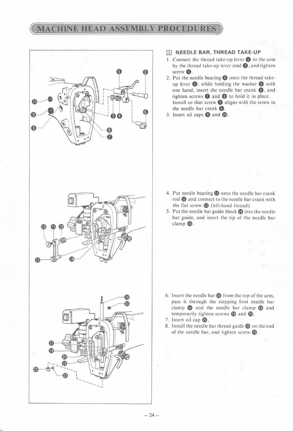
~MACHINE
HEAD
ASSEMBLY
PROCEDURES)
[!]
NEEDLE BAR,
I. Connect the thread take-up lever 0 to the
by
the thread take-up lever stud
sc
rew e.
2. Put the need le bearing 0
up lever
one
tighten screw s
In
the needle
3. Insert o
0:
hand.
in
stall so that screw
bar
il
caps 0 and
THREAD
wh
il
e holding the washer 0
sert the needle bar crank e.
f)
and
0 to ho
f)
crank e.
~
TAKE-UP
f).
onto
the thread take-
ld
aligns with the screw
-
and
tighten
wi
it in place.
arm
th
an
in
d
4. Put need le be_
rod
4D
the nat scre\\
5.
Put t
he
bar
guide.
clamp
6. Insert
7. Insert o
8. Install the needle
the needle
pass
it
cl
amr
temporarily tighten screws
of
the needle ba
aringf)
and connect to the needle
~(l
needle bar gu
and
insert the tip
6)
.
bar~
through the stepping foot needle
4D
a
nd
the needle
il
cap
fJ)
.
bar
r.
and tight
onto t
he
needle ba r crank
bar
crank with
eft-hand
id
thread guide 0 on the end
thread).
e block e into the needle
of
the needle
from the t
bar
fP)
and
en scr
or
of
clamp
~
ew
fl).
the
«)
-
bar
arm.
bar
and
- 24 -
Page 28
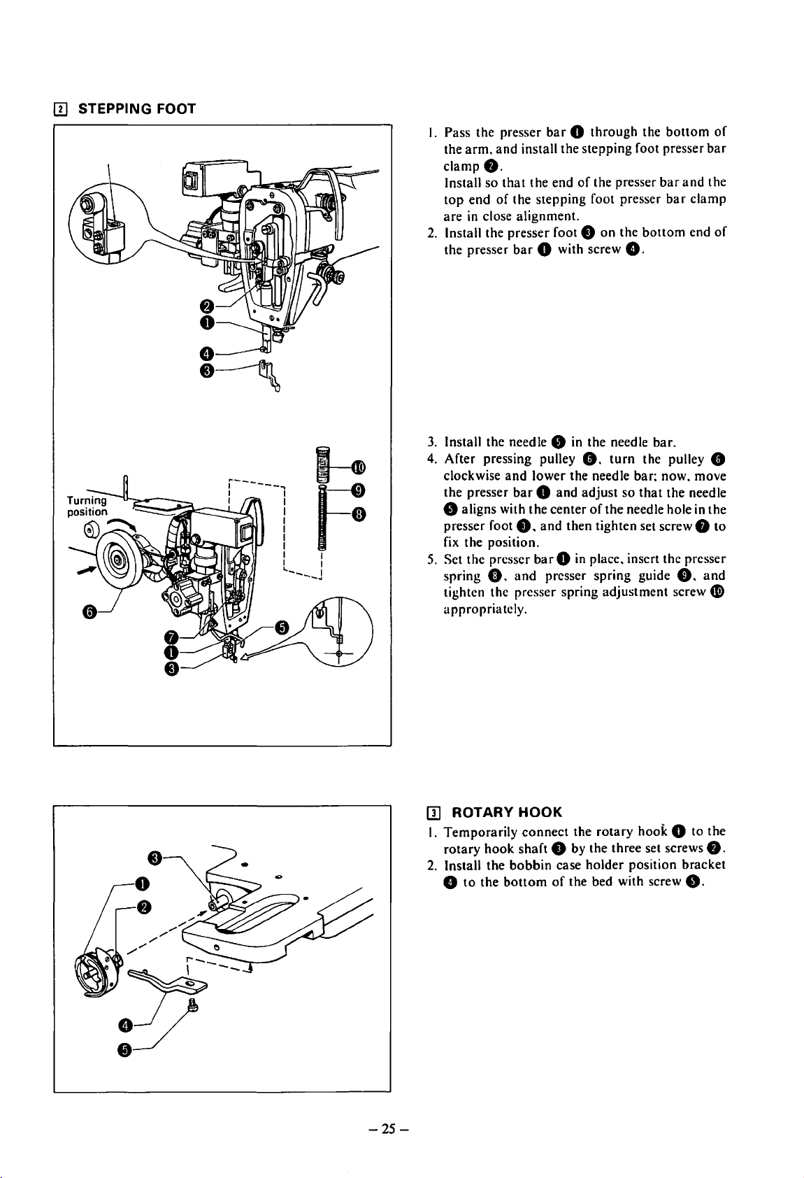
[!]
STEPPING FOOT
I.
Pass the presser
the
arm,
and
clamp
8.
Install so
top
are
2.
Install the presser foot 8 on the
the presser
3.
Install the needle 8 in the needle bar.
4.
After pressing pulley
clockwise
the presser
that
end
of
in
close alignment.
8 aligns with the center
presser foot
fix the position.
5.
Set the presser
spring
tighten the presser spring adjustment screw
appropriately.
o.
bar 0 through
install the stepping foot presser
the end
the stepping foot presser
bar
of
the presser
0 with screw
8.
and
lower the needle bar; now, move
bar 0 and
8.
barO
and
adjust
of
and
then tighten set screw
in
place, insert the presser
presser spring guide
8.
turn
so
that
the
needle hole
the
bar
bottom
the pulley 8
bottom
bar
the needle
and
clamp
end
e.
in
f)
of
bar
the
of
the
to
and
Ci)
[I]
ROTARY HOOK
I. Temporarily
rotary
hook
2.
Install the
8
to
the
bottom
r---
:?7
--
-25-
connect
shaft
bobbin
the
rotary
8 by the three set screws
case
holder
of
the bed with screw
hook 0 to
the
8.
position bracket
8.
Page 29
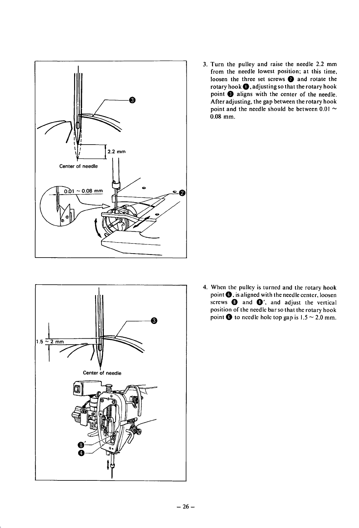
3.
Turn
the pulley
from the needle lowest position;
loosen the three set screws
rotary
hook
point 8 aligns with the center
After adjusting, the
point
and
0.08 mm.
and
raise the needle 2.2 mm
0.
adjusting
the needle should
so
gap
between the rotary
8
and
that
the
of
be
between 0.0 I
at
this time,
rotate the
rotary
hook
the needle.
hook
"'
~:
Center
f+-l
\/
of
-----.-
needle
2.2
mm
4.
When the pulley
point
e.
is
aligned with the needle center. loosen
screws
position
point 0 to needle hole
0
and
of
the needle
is
turned and the rotary hook
0'.
and adjust the vertical
bar
so
that
the rotary
top
gap
is
1.5"'
2.0 mm.
hook
Center
of
needle
-26-
Page 30
0
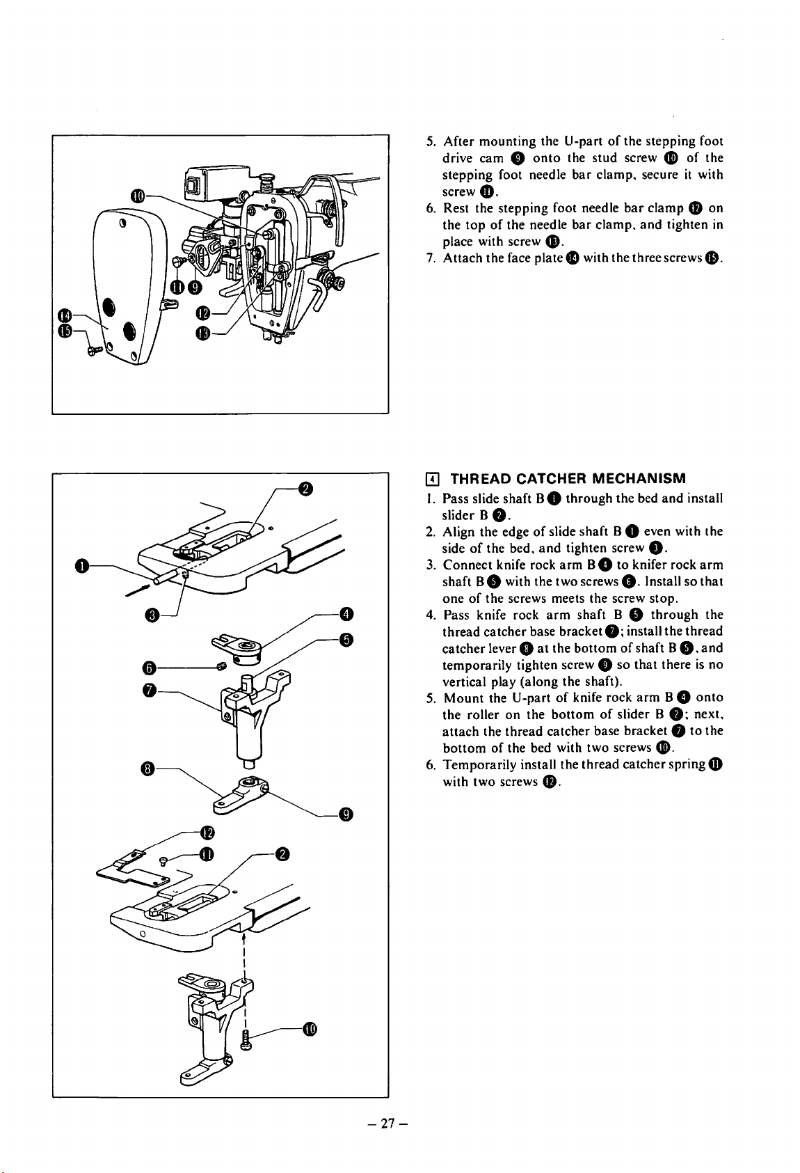
5.
After mounting the U-part
drive cam
stepping foot needle
screw
6. Rest the stepping foot needle
the
top
place with screw
7.
Attach the face plate4D with the three
[!]
THREAD CATCHER
I. Pass slide shaft B 0 through the bed
slider B
2.
Align the edge
side
3.
Connect knife rock
shaft B 8 with the two screws
one
of
4.
Pass knife rock
thread catcher base bracket
catcher
temporarily tighten screw 0
vertical play (along the shaft).
5.
Mount
the roller
attach
bottom
6. Temporarily install the thread catcher spring
with two screws
0
onto
4D.
of
the needle
41.
f).
of
slide shaft B 0 even with the
of
the bed,
the screws meets the screw stop.
lever 0
the U-part
the thread catcher base bracket 8 to the
of
and
tighten screw
arm
arm
at
the
of
on
the
bottom
the bed with two screws G).
48.
of
the stepping foot
the stud screw
bar
clamp. secure
bar
clamp
bar
clamp.
and
MECHANISM
8.
B 8 to knifer rock
0.
Install
shaft B 8
f);
install the thread
bottom
knife rock
of
so
of
slider B
shaft B
that
arm
G)
of
it
48
tighten
screws&.
and
install
so
through
0.
there
B 8
f);
next,
the
with
on
in
arm
that
the
and
is
no
onto
4D
-27-
Page 31

[[]
THREAD
0
TRIMMING
«o
I I
l....
---
-........
--.J
r----
I
I I
I
I •
I
I
I
I
MECHANISM
e\
~
--~~r
I. Install the slider assembly 0
trimming
2.
Install knife rock
arm
set screw 8
alignment
Pass knife rock
3.
thread
thread
A
8.
there
Mount
4.
the roller
temporarily
bracket
base bracket 8 with two screws
arm
A 0
shaft
A 8 with set screws 8
is
aligned with the position
hole when tightening
arm
shaft
trimming
trimming
and
temporarily
is
no vertical play (along the shaft).
the U-part
at
the
bottom
install
base
bracket
lever 8
on
tighten screw 0 so
of
knife rock
of
the
the
thread
8 with the two bolts
onto
the
thread
onto
knife rock
and
8.
Be
the
screws.
A 8
through
f):
install the
the
bottom
arm
slider assembly
trimming
of
A 0
0.
8.
sure
the
shaft
that
onto
0:
base
5.
Install the movable knife
CD
and
screw
tighten screw
so
that
the movable knife
or
thread
the pulley
arrow,
8
the
movable
after
screw
left.
knifeCii)
right
6.
Set the
the movable
two screws
horizontally.
7.
Turn
8. While pressing with
movable
the
bracket
of
center:
and
48.
4B
in the middle
catcher
knife41!)
C.
so
and
and
move
both
and
movable
knife
adjusting. tighten the
4B.
41!)
with flat head screw
At this time.
41!>
spring
and
temporarily tighten
that
the spring does not slide
lower the needle bar.
your
finger
sliding
it
the
thread
knife
41!)
aligns with the needle
temporarily
of
the screw hole
can be adjusted
G)
directly below
on
the
in
the direction
trimming
Cli)
so
that
two
top
of
the tip
bolts 0
the
the
of
base
-28-
Page 32

I!]
BOTTOM PLUNGER ASSEMBLY
0
•
f)
•
•
_bv3-rm
I.
Pass the
and
2.
Put the washer 8 on the
and
3. Align the end
the side
[1]
CYLINDERS
(I)
Thread Catcher Cylinder
I.
Connect
thread catcher cylinder base
cylinder mounting screws
2.
Temporarily install the
base
both
3.
Connect
and
and
connecting, check
cylinder moves smoothly,
tighten bolt
4.
Connect
tubes to the elbows.
5.
Move the thread catcher cylinder by
when the thread catcher spring
retracted, loosen screw
catcher lever
spring
0.5 mm.
6. Move the thread catcher cylinder by
fully advance the thread catcher spring
turn
adjust
left
oval hole.
bottom
install the
attach
of
the thread catcher cylinder 8
lever shaft 8
bottom
the
stop
of
the
the bed
lever
bottom
ring
8.
bottom
and
tighten screw
through
8.
lever shaft
lever shaft 8 with
8 with the two
8.
thread
8 with bolt 8
the bed
the thread catcher lever 0 with link pin
secure the link pin with
and
the
thread
8
the correspondingly numbered
0
4D
and
movable knife
the pulley, loosen the two screws
the needle so
and
right sides
and
thread catcher base
catcher cylinder rod
that
and
the two screws
G)
so
that
that
of
the needle when it is in the
catcher
the two screws 8 to
stop
ring G). After
the thread
and
then firmly
and
move the thread
the
gap
between the
f)
is
between 0.3
the spaces are even
8.
8.
8.
hand
4D
hand,
CD;
the bed,
8.
to
the
cylinder
joint
8
8.
catcher
air
and
is
fully
"'
and
next,
41.
and
on
Thread catcher
spring retract
Thread catcher
spring advance
-29-
Page 33

0.3-0.5
mm
-
(2) Thread Trimming Cylinder
I. Install the
thread
cylinder
2.
Temporarily
base
the two set screws
3.
Connect
8
and
0
and
these.
moves
screws
4.
Connect
tubes to the elbows.
5. While lightly pressing the
knife
trimming
and
adjusting
base
movable knife
thread
trimming
mounting
0
on
the cylinder
the thread
the
thread
attach
confirm
smoothly.
8.
the correspondingly numbered
CD
with
cylinder by
move the thread
the
4B
to
trimming
cylinder base 0 with the two
screws
install the thread
e.
connecting
8.
trimming
trimming
stop
that
the
and
your
gap
between the slider4D
within 0.3
is
moved
leverO
ring
f).
thread
then tighten the two set
finger. move
hand;
trimming
"'
both
cylinder 8
trimming
cylinder rod
After connecting
trimming
top
of
loosen set screw
0.5
mm
forward
on
cylinder
plate 8 with
with link pin
cylinder
the movable
the
thread
lever
and
when
and
the
joint
air
G)
0.
slider
the
back.
---0
(3) Bottom Cylinder
I. Install the
cylinder base 0 with the two cylinder
screws
2.
Temporarily
onto
2 set screws
3.
Connect
bottom
stop
that
then tighten the two set screws
4. Connect the correspondingly numbered
tubes to the elbows.
bottom
cylinder 8
e.
install the
the
thread
catcher
8.
the
bottom
lever plate 0 with link pin 0
ri.ng
f).
After connecting these.
the
bottom
bottom
cylinder base 8 with the
cylinder rod
cylinder moves
on
the
bottom
mounting
cylinder base 0
joint 8 and
and
attach
confirm
smoothly.
8.
the
and
air
-30-
Page 34

5.
Install needle plate S ~ with two flat head
screws
6.
the
the
needle plate; next, raise the
fully,
plunger~
then firmly tighten the two set screws 8 in this
position.
49.
Moving the
bottom
bottom
and
bottom
plunger~
plunger~
adjust
is I mm
cylinder by
and
with the
so
that
above
the needle plate,
hand.
align the
top
surface
bottom
the
top
first lower
top
plunger~
end
end
of
of
of
the
the
and
(Up)
About 1 mm
(Down)
* If the up
is
gap
Likewise, if the
decrease the gap.
[!]
I.
Mount
foot lifter cylinder
bolt
2.
Mount
lifter cylinder
secure it with the E-shaped
3.
Mount
support
material cylinder 5 ~ with two Allen bolts
4.
Mount
G)
screw
5.
Mount
bracket
connect the
6.
Finally. push the
screwdriverto
does not. loosen screw
49.
and
and
down
stroke
less
than I mm,
between the
NEEDLE BAR
ASSEMBLY
the cylinder bracket 0
loosen nut G),
stopper
stroke
DESCENT
f),
and
8.
the piston rod
the
hook
joint 8 on
f),
insert the link pin
bracket 0
0 with the two screws
the
coupling
on
the thin material cylinder 5
in
the nylon hose nipple
the cylinder
0 with
air
adjust
the
then retighten the screw
hook~
support 0 on
four
Allen bolts
hose
4D
coupling
confirm
0
hook
so
of
the
bottom
and
increase the
CD
and
rod
is
greater
secure with the Allen
than I mm,
GUARD
on
the presser
the presser foot
snap
ring O.
on
the cylinder
0.
and
with the Allen bolt
~.and
e.
the cylinder
49.
to
the
nipple
hook
41
that
it moves freely. If it
and
Allen bolts
that
it does move freely.
and
bolts.
plunger
joint
8.
the
and
CD.
with a
CD
&.
and
thin
CD.
then
then
and
-31-
Page 35

~
STANDARD
ITJ
ADJUSTMENT
ADJUSTMENTS
OF
THE
ROTARY
0
~
HOOK
~
Center of
:
?-r---l ----.
I I
11
the
nee
* T urn the pulley and rai
the rotary hook
aligned with the
[I]
ADJUSTMENT
e to make an adjustment in such a
ce
nter of the needl
OF
2.2
mm
dle
se
the needle b
THE
NEEDLE BAR HEI
0
ar
2.2 mm from the lowest
wa
e.
GHT
y that
p o~itio n.
th
Then.l
e hoo k point 0 of
oosc n the set screws
the rotar
y hook becomes
f)
a
nd
turn
Center of the needle
Turn the pull
8 . a
nd
face p
ey
la
0 to needle hole top g
OJ
ADJUSTMENT
and align the rotary hook point with the needle center. Remove the
te e . loosen screws 0 a
ap
is 1
.5
OF
THE
CLEARANCE
nd
"' 2.0 m
o.
and vertically adjust the needle
m.
BETWEEN THE
NEEDLE
*
Turn
rotary hoo k w
loos
en
moving the rotary hook 8 so that
cl
eara
nd the hoo k point of the rotary hook.
a
bar
AND
the pulley a
it
the scr
ew
nce ofO.
OI "'0.08 mm betw
so that the ro tary hook point
THE
ROTARY
nd
align the hook point of th e
h the center
s 0
and
make an adjustment
0
thr
ee sc rews
HOOK
of
the needle. T hen.
there
een the needle
by
i a
- 32 -
Page 36

[I]
ADJUSTMENT
+
OF THE PRESSER FOOT
* Lower the presser foot
and
make
following
To
lower the presser foot:
adjustments
procedure.
to
the lowest position,
according
© Before sewing
Turn
the test
and
then press the step back switch
presser foot.
© When emergency
sewing
First release the emergency
step back switch.
down
to lower the presser foot
©
During
First release the test/intermediate sewing switch.
and
then press the
presser foot
mechanism will again function when the
tcst/intcrmcd iatc sewing switch is pressed again.
(I)
Turn
need
lc
presser foot
adjustment
cap
0.
adjustment
After
the presser
screw
Note:
being used,
misaligned
On
the
sufficiently, it
occur.
(2) Loosen the set screw
the position
presser foot
surface
and
intermediate sewing switch
to
lower the
stop
switch is pressed
stop
switch. press the
and
set the presser foot
position. Now press the read/write switch
to
the lowest position.
test feed
read/
write switch
to
the lowest position.
the pulley.
enters the center
loosen the set screw
making the necessary
and
check
of
the needle hole
f).
If not. loosen the presser
screw 0 sufficiently. remove
by moving the presser foot.
adjustment.
adjustment
screw 0
to
confirm
0.
to
and
and
lower the
The
that
make
0.
that
when
the
stepping presser foot is
the
sewing material can become
if
the
presser foot
other
hand,
can
cause stitch-skipping
0.
at
which the lower surface
f)
lightly
of
the sewing material.
is
if
it is
and
contacts
lowered
not
then
tighten it at
lowered
the
to
the
on.
during
to
the
feed
the
of
the
the
an
tighten
the set
not
too
far.
to
of
the
upper
Ill If the stepping presser foot
If the stepping presser foot
can be removed in the following procedure.
(I)
Remove the face plate.
Turn
(2)
(J)
the pulley.
highest position.
Remove the
stepping presser
-33-
stud
is
not
is
not to be used.
and
raise the needle bar
screwO.
cam
and
f).
to
be
used.
it
to
the
then remove the
Page 37

[!]
WORK
CLAMP
ADJUSTMENT
[[]
AIR PRESSURE
• Use an air pressure at 5 kgf/cm
Pull
up
the cap
adjust the pressure. After adjustment, push the
cap down
• When water has gathered in the bottle
the air cock 8 and push the drain cock 0
remove the water.
to
lock it.
ADJUSTMENT
at
the
top
of
2
•
the air unit 0 and
8,
close
to
To
adjust the work
clamp
to
the
top
nut
0 and slide nut
opening increases. Adjust the nut left
* Increasing the work
opening
increases work
clamp
install a
of
the needle plate should be within 45
f)
in
or
clamp
clamp
standard
out
and
opening makes
pressure.
work
clamp.
adjust
as needed. When adjusting. if
or
right
as
needed.
it
harder
The distance from the
~55
to hold material securely. Decreasing the work clamp
-34-
mm when the work
nut
[2]
WORK CLAMP POSITION
bottom
clamp
f)
of
the back
is
raised: if
is
turned right. the work clamp
ADJUSTMENT
The
work clamp should be positioned so
work
clamp
adjust. loosen the four Allen screws 0
the clamp guide
necessary. When using a unit work
to adjust the
right
and
pressure evenly over the material.
f)
in
the
arrow
clamp
guide angle the same on
left.
of
it
is
not.
direction
clamp.
the work
loosen
as
to
apply
and
move
be sure
both
To
as
Page 38

III MOVABLE KNIFE
ADJUSTMENT
0
* Adjust after releasing the
I.
Remove the screws 0
••
2.
Turn
the pulley
3.
While pressing
8 with your finger
8 in the
and
tip aligns with the needle center.
arrow
screw 8 to adjust
and
and
lower the ·needle.
on
the
top
and
sliding the movable knife
direction. loosen set screw 8
so
that
air
pressure.
remove needle
of
the movable knife
the movable knife
plateS
Movable knife
* When
[!]
thread
illustration. Note
THREAD
~-
If
this part is not shaprened
smoothly, that causes the
upper thread to snap.
trimming leaves the tip
that
the movable knife
TRIMMING
SLIDER
-
0.3-0.5
mm
::e>
of
the. thread rough
cannot
ADJUSTMENT
be sharpened: replace
Fixed knife
or
ragged. sharpen the fixed knife as shown in the
it
with a new movable knife.
0
•
* Adjust
While pressing lightly
loosen set screw
between 0.3
after
"'
0.5 mm.
releasing the
on
the
8
and
move knife rock
air
pressure.
top
of
the movable knife 0
arm
and
moving the slider 8 by hand in the
A
8.
adjusting the gap between the
* Install the lower thread catcher spring 8 directly below the movable knife
-35-
slider&
0.
arrow
and
the slider base 8
direction,
to
Page 39

1!2]
THREAD CATCHER SLIDER
6)
ADJUSTMENT
0.3-0.5
I
_==iiJ?> l
0
I
Thread catcher spring retract Thread
* Adjust
(I)
(2) Move slider B
[ill BOTTOM PLUNGER
after
releasing the
Move slider B 0 by
rock
arm
B
8.
adjusting
catcher
spring 8 is
0 by
needle is lowered
that
the spaces
into
on
hand
within 0.3
hand
the oval hole, loosen set screw G
the left
ADJUSTMENT
mm
air
pressure.
and
fully retract the
both
front
"'
and
with the
and
right sides
catcher
and
0.5 mm.
Needle
spring advance
thread
back so that the
thread
of
the needle
catcher
catcher
spring
8:
gap
between the movable knife 8
spring 8 fully
and
move the
are
equal.
loosen set screw G
advanced.
thread
turn
catcher
spring
and
move knife
and
thread
the pulley: when the
8.
adjusting so
* Adjust
(I)
(2) Move the rod
* Adjustment
(3) With the
after
releasing the
Move the rod
bottom
stopper 8 and
8
plunger
and
lever
is
bottom
move the
8.
~A-
'
(Bottom
(Bottom up)
air
pressure.
joint
0 by hand
e.
adjusting
joint
0 by
rod
joint 0 so
easier if the cylinder has been disconnected.
lever G raised manually.
bottom
and
so
that
hand.
and
that
plunger.
lower the
the
top
lift the
the
top
adjusting
of
bottom
of
turn
so
down)
bottom
the
bottom
the
bottom
the pulley
that
~
plunger
plunger
the needle
8.
Loosen
plunger
8:
plunger 8 is
and
and
loosen nut e
lower the needle bar: loosen the
is
in the
the
two
top
of
the needle plate
and
I mm above the
center
of
the needle hole in the
screws 8
adjust
top
and
move the
are
even.
the
gap
between
of
the needle plate.
two
set screws
Needle
the
bottom
-36-
Page 40

[ill
THREAD
(third
TRIMMING
valve
from
bottom
Thread catcher speed
CYLINDER
in
eight
SPEED
valve series)
ADJUSTMENT
About
20.5
mm
8
0
Insertion speed
8
0
• Movable Knife Speed
If the movable knife speed
loop will be late
possible by loosening nut 0
• Movable Knife Returning Speed
If the movable knife returning speed
the needle thread may be
continues.
trimming finishes before the feed mechanism advances to the next sewing position. Adjust by loosening nut
and
turning speed control
* Values
in
and
and
will result in thread trimming misses
the above illustration may vary slightly. Use them as a guide.
is
slower
may result in thread trimming misses. Adjust the movable knife to insert as quickly
too
than
necessary. the timing
and
turning the speed
is
faster
short.
Furthermore.
control
than
necessary. the
if it
of
the movable knife entering the
upper
f).
thread
will be
cut
by only the fixed knife,
is
too slow. the thread will not be
and
defects in sewing. Therefore. adjust so that thread
cut
until sewing
e.
thread
as
and
8.
[IT]
THREAD
Insertion speed
CATCHER
CYLINDER
ADJUSTMENT
About
(fourth
20.5
valve
mm
from
...
Thread catcher
speed
•
Thread
If the thread catcher speed
knife's thread trimming operation
necessary, the thread catcher will strike the needle before the thread trimming
Therefore. loosen nut
trimming.
• Thread Catcher Returning Speed
If the thread catcher speed
and
the
thread will not be caught. Therefore.loosen nut 8
the upper thread as consistently
* Values in the above illustration may vary slightly. Use them as a guide.
Catcher Speed
a longer
thread
upper
catcher will retract
is
faster than necessary. the
and
0
and
turn
the speed
is
faster
than
thread will be left
after
the thread has pulled
short
result in lower
control
is
necessary, a
on
the
back
as possible.
thread
catcher
thread
trimming misses.
f).
adjusting to a speed which
upper
thread will be caught by the thread
of
the sewn article. Furthermore, if it
out
of
the oval hole in the thread catcher
and
turn
speed control G. adjusting
spring will advance
top
in
eight
Furthermore.
operation
does
not interfere with thread
is
slower than necessary,
to
a speed
valve series)
during
the movable
if it
is
slower
ends.
catcher.longer,
and
that
than
the
upper
will leave
is
-37-
Page 41

~
BOTTOM CYLINDER SPEED
L;lt;ng,.,.edt
ADJUSTMENT
(fourth
About21 mm
valve
from
bottom
in
eight
valve series)
""'"'"'
•
Bottom
A synchronization signal
too
of
bottom
•
Bottom
If
Therefore. loosen nut
mechanism proceeds to the next sewing step.
* Values
[ffi WORK CLAMP CYLINDER
Plunger Lifting Speed
slow. sewing will continue for several stitches with the
the
bottom
the descent speed
plunger will be lost. Therefore. loosen nut 0
plunger operates
Plunger Descent Speed
is
in
the above illustration may vary.
.,
...
~
at
the first stitch causes the
as
too
8
quickly
slow. the
and
as
possible.
bottom
turn speed control
SPEED
ADJUSTMENT (second valve
bottom
plunger may strike the feed plate when material
8.
Use
them as a guide.
plunger to rise. Consequently. if the lifting speed
bottom
adjusting so
and
plunger
turn
speed
that
from
in
the lowered position.
control8.
the plunger
bottom
adjusting
drops
in
eight
is
and
the effect
so
that
the
is
being fed.
·before the feed
valve series)
~
o...,.,
•
Work
Clamp
If
the work
and
•
Work
the work
If
striking the feed plate. Loosen nuts
banging. .
Note: Adjust speed controls
* Values in the above illustration may vary.
clamp
turn
speed controls 8
Clamp Descent Speed
clamp
operate
'""
Lifting Speed
lifting speed
descent speed
at
the
same
is
faster
and
8.
is
8 and G.
speed.
than
necessary. the entire work clamp will vibrate. Loosen nuts 0
adjusting
faster
than
8 and 8
and 8 and 0 in
Use
to
a speed where the work clamp does not vibrate.
necessary. a banging
and
turn
speed controls 8
pairs so that both right
them as a guide.
-38-
sound
and
8
may be heard from the work clamp
and
0.
adjusting so
and
left work clamp cylinders
that
there
is
no
Page 42

1m
PRESSER FOOT LIFTER CYLINDER SPEED
(third
valve
from
bottom
in
eight
valve series)
ADJUSTMENT
t Uft;"l! opood
~
o
...
ont
., ..
,
• Presser Foot Lifting Speed
If the presser foot lifting speed in slower
or
cassette. Therefore. loosen nut 0
as possible.
• Presser Foot Descent Speed
Note
that
presser foot descent speed
nut
8.
and
turn speed control valve 0
* Values in the above figure will vary slightly with different machines: use these us a guide.
than
and
turn
is
constant.
to
necessary. the presser foot may strike
speed
control8.
and
speed control valve 0 will not vary it. However. loosen
adjust as shown
adjusting
in
the above picture.
so
that
and
damage the work clamp
the presser foot rises as quickly
ill]
MOVABLE
KNIFE
TIMING
ADJUSTMENT
The thread trimming signal
bar's down position. However. if the solenoid valve
turns
on
with the transmission
lowest signal. the movable knife will operate before
the
upper
thread loop
thread will not be cut.
movable knife timing
circuit
board.
to
turn
transmitted,
trimming misses.
Delay time can be adjusted
each. Refer to the table on the next page for dip
switch positions.
* Switches
dip
switches
OFF.
Note:
set a delay time for the solenoid valve
on
after the needle
and
adjust to a timing for no thread
No.5"' 8 of
are
not used. They should be set to
The
movable knife timing
because the needle lowest signal
electrical signal) causes the thread trim-
ming mechanism to switch the solenoid
valve,
air
pressure causes the cylinders to
operate.
the precision
and
is
adjusted
is
formed
To
prevent this. switch. the
dip
switch
bar
in
the movable knife timing
signal positions may vary due
of
mechanical parts.
to
the needle
of
the needle
and
the upper
on
the control
lowest signal
16
steps
of
is
adjustable
10
bar
ms
(an
is
• It stands for
70
ms.
-39-
Page 43

0 This table shows the
Dip switch
I
CQTI
[QEEJ
OEJ
2
0~
I
I
0 1-
I
0:\
1:
OK]
I
I
02TI
c::QD
I
[JK]
o
c::QTIJ
CQKJ
[QED
I
I
I
t-F
01'\
o~
I
I
[QED
I
[QITJ
CQS::J
I
I
[QIT]
[illiJ
I 01- 1- I
I oFF
I Ot-1-
de
lav time
3
re~ulting
4
02TI
D2D
DB:]
02TI
L:.QBJ
DB]
ors:J
CQD
from dip switch positioning.
Delay time
0 ms
10
ms
20
ms
30
ms
40
ms
50
ms
60
m
~
70 m
~
I 2 J 4
OK]
[QEEJ
[Qs::J
[Qill
OITI
CQEO
[Qs::J
CQEO
Dip switch
CQKJ
OK]
[QEE]
[QEtJ
DID
OK]
CQIEJ
OIITJ I
I O'i I
DID
CQSJ
c:::Qs:::J
I
OFI-
I [QEEJ
I 01-1- I
01-1-
I
I
OH
·
I
[QED
[QEEJ
OillJ
[illiJ
[QITJ
[QIT]
I 0
1-1-
Delay time
I
80
m
~
90 ms
100
ms
I
10 rns
1
20
ms
130m~
140m~
150
ms
(D
elay time
I).:Lu 11mc 0 ( (
I
hn:•~
1111\'ll."'-
and thr
tru11n11n~
fj
ead trimming misses]
50
nh
f'ol)
()
(
2
XII
nl'
70
rn'
)i(J
zn,
~,
f
',\
·:ln8~
~~~
rn
..
HXlnh
flO
100
[Time between thread trimming operations and
thread trimming misses]
~
~
I
Hn~
li
me:
3~
c.
--
~
l..ih
nn
il
tunc
,£
nh
(
~
Ill Selection
mi
sses
Thread trimming timing will
vario us co nditio n
normally
of
a delay time for no thread trimming
va
ry with each
s.
However. became th ere
around
4 ~ 5 speed
~c
ttin
gs
of
arc
with no
trimming misses. adjust to the timing speed that
be
st matches the sewing conditions .
( I) Feed programs
th
read trimming
compared with
long
(30 seconds
• Fast timing results in many
mi
sses.
in
which t
operatiom
pro
grams
or
more).
he
time between
is short
in
\\hich this time is
thr
ead trimming
a!>
• Likewise. slow timing results in fewer thread
trimm
ing misses.
-40-
Page 44

Delay
Accclcra-
2.
;;i
ted
~
[
hook
;'1-
Standard
§·
hook
21---+--J
oil
Delayed
hook
time
>trOk<
timin~
timin~
timin~
(2) Needle
When the
•
Slow
bar
stroke
and
thread trimming misses
hook
timing
is
accelerated
timing increases thread trimming misses.
• Likewise. fast timing decreases thread trimming misses.
When the
timing
is
delayed
hook
• Fast timing increases thread trimming misses.
• Slow timing decreases thread trimming misses.
(3)
Sewing thick
trimming
and
misses
thin materials
and
thread
• With thick materials. the delay time has a
tendency
to
increase.
• Likewise, with thin materials. the delay time
has a tendency
nearly the same when timing
to
tends
to
decrease. (T!Je delay time
change more.)
is
fast; slow timing
is
Do:lay
H
-~
.::.1;,
9
3
s·
..
Movable
time
Thick
material
Medium·
thick
material
Thin
material
.
kmfe\
--:;::.1
Hook_____,./
(
(
)
(
(
\~
~(sewing
.'
_,...,-Upper thread
_,a,
(m~edle
"----
s1de)
Lower
Upperthread
edge)
thread
thread
(4) Special threads
With
andalia
time has a tendency
and
thread
and
similar threads. the delay
trimming misses
to
decrease the same as
with thin fabrics.
(5)
Short
As
shown
needle thread
in
the right figure. before a normal
after
thread trimming
loop has formed. the movable knife may
advance, catch the needle
hook
and
trim the thread with the knife. When
this happens the needle
short.
and
thread come-off will
thread
thread
side with
will become
occur
sewing starts.
If the needle thread
for normal
increasing
the
* When timing must be between 60
thread
account
temperature
trimming
for timing variations resulting
and
is
extremely
thread
trimming
delay time.
misses. select a 70
humidity .
short.
by slightly
"'90
ms
the
when
adjust
ms for no
setting
to
from
-41-
Page 45

Point
of
Origina
l
(X-O
•Y -0)
[ill
ORIGIN
(I)
Origin Posit i
I. Remove the four installation scre
remo ve the clamp
2.
Remove the four screws E). and remove the feed
plate
3.
Remove the three screws
slider
4. Install the program referen
5. Mo ve the feed guide to t
Turn
6.
7.
Depress the work clamp lifter switch. and after
setting the c lamp
depr
ess the st
8.
The feed mechanism wil move to the origin
pos ition and the emergency
ill
uminate.
Turn
9.
that the needle tip aligns with the origin position
on
the program reference plat e
*
To
program the machin e, press key
mechanism wi
way. the
the origin position.
POSITION ADJUSTMENT
on
Check
f).
e.
0.
cover
0.
ce
he
the power switch on.
in
the cl
art
switch.
the pulley. lower t
ll
mo ve to the origin position. This
programmer
he
can a lso be used to check
ws
0 and
and remove t
plate
f).
center.
amp
ing position.
stop
lamp will
needle and confirm
f).
IIJ:
the feed
he
(2)
Origin
[X-a x
I. After pushing the
f).
2. Remove the two screws e and after
remove table right
3. Install needle pla
4. Adjust by loosening the four set screws
5. After adjustmen t. check the origin position.
6. After removing needle plate L
Pos
is
Adjustment]
iti
on
Adjustment
fee
d guide assembly to the le
compre
0.
te L f)
.
f)
and insta
ft
rear. remo
ssing the bellows assembly G. remove the four Allen bolt s 0 : next.
f)
and
mo\
lli
ng table right
-42-
ve
the twelve screws O. and remove needle plate L
·ing the X-position
0.
reinstall need le plate L
dog
0 .
f).
Page 46

[m
OVERLIMIT
SWITCH
ADJUSTMENT
[Y -axis
7. Push the feed
8.
9.
Adjustment)
Loo
sen the
Y-po
sition
After
two
dog~.
adjustment.
guide
scr
check
assembly
ews
f):
to the rear.
adjust
the o rigin position.
by moving the
@)
$ ®
~I
f-
-
6
00
3~4mm
(30 ~ 40
[
X-axis
I.
Refer to
2. Push the feed g uide asse
3. Remove the twelve screws. and remove needle
4. Remove the eight Allen
5. In sta
6. Ins
7.
Turn the
8. Using
pul
O.
9. In the same way. move the f
pulses) f
ove
PLS)
Adjustm
steps I
ll needle
tall the prog
power sw
the prog
ses) f
urth
er
adjusting
urth
er
rlimit
switch 0
ent)
"'3
in
plate
L.
ram
reference
itch
ramm
er, move
to the ri
so that the
to
ght fro m t
the lef
turns on.
"Or
igin
Position Chec
mbly to
bolt
on.
overl
t; n
the rear.
s.
and
plate.
the feed mecha nism
he
orig
imit
switch 0
eeder to the left side by using the p
ow, loo
sen the t
remove
in position
1 ~ 3
(10
both
wo
l
l_j
I
mm
~
30
PLS)
k" and remove the
plate
L.
right a
nd left tabl
to the
origin
pos
; n
ow.loosen the tw
turn
s o
n.
rogrammer.
Allen
bo
lts 0 and m
work clamp
es.
iti
on.
and move
o Allen bolts
and
ove the
. feed plat
the feede
f)
then move
X-ES dog
and
0.
e. and
r
3"'
move the
it I
"'
a
djustin
slider
cover.
4
mm
(30 "'40
X-ES
dog
3 mm ( 10"'
g so
that the
30
*
Co
nfirm that
doe
s.
origi
n limit
sw
itch 0 always
turns on before
-43
-
over
limit swi
tch 0 on
the
initia l
pos
ition limit side
Page 47

I
@)
®
@)
tl
[Y
-axis Adjustm ent)
10.
Using the
pulses): loosen
II. In the same way. using the program mer mo
mm
4D
* Check that o
doe
12. After removing needle plate
pro
(I
0 ~ 30 pulses
turn
s on.
s.
gram me
ri
gin limit switch
r.
move the feeder
th
e four Allen bolts 0
):
loosen the two Allen bolts
to
and
G)
always turns on before overlimit sw
1.
. install table right
(/)
_J
Ea.
E~
I J
'<~"
/
LJ
l o
M£2
0
l!l
N
the origin position.
move Y-ES
ve the feeder
4D
dog4D.
to
the opposite side. and then move
and move
and
table left. a nd then reinstall needle plate
and
move the feed
er
forw a rd 3 ~ 4 mm
adjusting so that overlimit
the Y-ES dog. adjusting so
it
ch 0 on the in itial pos
sw
itch 0
it a further I
that
ovcrlimit switch
it
ion limit side
(JO~
turn
L..
40
s on.
"'J
~
r---
PULSE
----
MOTOR
--------
BACKLASH
------------------------------
[Y-axis Adjustment)
I. Remove the four screws
2.
Loosen the six A
is within
Also.
0
co
nfirm th
ll
en bolts 0
"'
0.03 mm when th e
at
the Iced gu ide assemb ly mo\'es smoothly when
ADJUSTMENT
0.
and remove the
and
move the rack
power
switch
arm
rear cover 0 .
0.
adjusting so th at t
is
on
and
------------------------
he
the
fee
d guide assembly
it
is
gear
assembly
i
~
moved back
pushed forwa
----
--------
f)
and rack 0 backlash
and
forth by hand.
rd
and back by hand.
-,
-44-
Page 48

[X-a.xi~
I. R
2. T
.1.
4. Remme
Adjustmen
emo\'e
th
en
reinsta
urn
the
f)
a nd shi
onlyO~
when
the
left by
Make
smoothly
then
rein
needle
pom.:r on. l
ft
O.O.I
feed
hand
sure
both right
needle
sta
t]
plate
1..
ll needle
the
mmofpla~
guide
.
the
ll
needle
pulse
feed
plate
plate
oosen
motor
assembly
and
L.
plat e L.
remO\e
L.
the
mount 0 so
inth
egearassernbly
is
guide
lef
t.
reinstall
table
rig
four
/\lien
moved
assembly
tab
le
right.
ht.
there
righ t
1110\
and
holts
is
O
and
'es
and
[ill BELT
I. After
asse
2.
Remove the t
3. Rem
4. Rem
5.
Move the feed guide
TENSION
turning
mbl
y
e.
ove screw
ove
the
ADJUSTMENT
the
air
wo
Allen
8.
a
nd
two screw
assembly unt
off.
disconnect the
bolts 0 on
remove the left side
s
f).
and compr
il
the
it
air
tub
back
of
cove
ess the
meets the
e O.
Remove
the
support
r
0.
bellows
right-side X-ES dog.
assem
the two
.
bly 0
Allen
to
the lef
bolt
t side.
s
f).
and
remove
the
air
uni t
6.
Align
and
set
accessory
7. H
ook the belt
8. Loosen nut
adju
st
so that
top of the belt aligns with the b
9.
After
adjustment, first tighten
4D
screw
on
an
tension
d a ft
er loose
49
tensio
n p late C 0
pla
te A
nin
m
eets tension
ottom
bolt
4D
a
nd
g Allen
plate
of tension
4D
, t
align
bolt
A
hen
at the
rig
ht edge of table
it
wit
h t
he ext
49.
loosen
left
4D
when tension plateD
plate C
tighten
f)
bolts
.
49
ended part
and
rig
ht All
f)
Turning bol
and
set
left~-
of
en
is
t
4D
with nu
- 45 -
tension
bolts
raised
to
the
ts
plat
e C
4D
and turn
with the
4D
index
right increases
.
f)
.
Allen
fin
ger
belt
bolt
4D
, a nd
tension.
to
the
Page 49

[m
ENCODER
8
0
(POSITION
DETECTOR}
ADJUSTMENT
(I)
Encoder
Opening
I. Re move
encoder
2. L
oosen the
and
cover.
turned
(2)
Synchronization
Turn the pull ey by h
bar
the
needle
the machine motor
loosening
synchron
Thi
*
the machine
length 4.5
is less
needle
signa
Cover Removal
the
cover
two
open the r
the rear
several
above
needle tip is 0
plate;
th
izati
s synchronization signa l is o nl y used when
mm
than
bar
l.
thr
ee
f).
rear
ear
cover
times and
the
needle
now.
e t
wo
on
sig
speed
or
4.5
mm.
down
screws
cover
cove
r
0.
mounting
used as
Signal
"'
Position Adjustment
and and
bar
0.5
mm
adj
ust
so
circuit board
screws 0
nal
slit O.
is 500
"' 800
more);
when the stitch leng
this si
posi tio n syn
and
Rear
O. a nd
mounting
When
down pos
above
that LED
gnal is used as
remove
screws 8
open
screws e can
stops
raise
the
ition until
the top
goes out by
and move the
rpm{with stitch
chronint
Cov
er
the
ing the
be
support.
needle
of the
No . 2 on
th
the
ion
LED
4
(Needle up)
LED
3
(
Thr
ead trimmi
LED
2
(Synchronization)
LE
D 1
(Needle down)
0 0
ng)
T
hread
(3)
tion Adjustment
Turn
bar
LED
goes out by l
mo
This
*
when
thr
also
adjust
p. 40).
the
incr
Need
(4)
Turn the pulley by
bar from
is
Now.
moto r ci
two
s
Trimming
the
to
its
No.3
ving
the
signal a l
the
ead
trimmin
functioning
the m
If
movable knife inserti o n t
eased.
le
Up
II
"'
14 mmabove
adj
rcuit boa
sc r
ews 0 and moving the needle
lit~
.
Sig
pulley by h
down position.
on
oose
thread
stitch le
ovab
the dow
Signal
its highest pos
ust
so
and and
the machine
nin
g the
trimmer
so functions as
ngth
g signal is
as the sy nc s igna l. be s
le knife insertion
n s
igna
Posit
hand
thetopofth
that
LED
rd
goes
nal
(down signal)
lower
l\ow.
adjust
motor
two
screws
signa l slit
the
is
4.4
mm
or less. If this
adjusted
l position
iming
ion
Adjustment
and l
ower the needle
ition
until the need le tip
eneed
No. 4
on the machine
out
by l
Posi-
the ne
edle
so
circuit
board
f)
0.
sync signal
when it is
ure
timing
is
delayed.
sho
uld be
le pl
oose
ning
up
signal
that
a
nd
to
(see
ate.
the
(5)
0 ~ 0.5
mm
Thread
signal
I
trimming
Synchro
n
ization
signa
l
-
Need le
Loosen the two
down
I on the
be twee n the time
the
needle
the
down position when the pull
han
d.
- 46 -
Down
signa l slit4D.
Position
machine
up
pos
screws
th
Adjustment
4D
and move the needle
adjusting
moto r circuit board
e needle
ition and the
so that
bar
desce nds
tim
ey
e it reaches
is t
LED
No.
goes out
from
urn
ed by
Page 50

Rl
Synchronization signal
R2
Thread trimming signal
R3
Needle up signal
R4
Needle
down
signal
(6) Needle Position Detector Sensitivity Adjust-
ment
The
sensitivity
needle position detector may
the machine
Therefore, periodically check the sensitivity
this phototransistor.
I. Apply the negative
negative side
encoder
positive
terminals.
circuit
(+)
of
the
phototransistor
drop
motor
of
side
To
test, set the testers range to
from operating normally.
(-)
side
of
a tester to the
the
10
).1F(25
V)capacitoron
board,
to
each
and
then apply the
of
the signal's resistor
and
for the
prevent
of
the
10-V
DC.
2.
Turn
the power switch on
hand; check if the
and
R4
is
synchronization, thread trimming, needle up,
and
needle
confirm
circuit board are
3.
As
output
machine
Also check
revolution, signals
locations.
that
performed
voltage
is
output
over 4.5 V in each
down
positions. At this same time
LEOs I
not
in
step 2 above, confirm
of
R I
in
any
position not specified above.
that
are
and
turn
the pulley by
voltage
"'4
on
illuminated.
"'
R4
in
motor
not transmitted from two
of
R I, R2. R3.
of
the machine
is
below 2 V when the
one machine
motor
that
the
the
0
(7) Speed Detector Sensitivity Adjustment
If the
photo
interlapper
detector
detected
speed. stop
will illuminate. Accordingly. if the machine
suddenly stops during sewing
cy stop lamp illuminates. it
adjust the interlapper sensitivity for the speed
detector.
L
Turn
speed by
machine
2.
Turn
circuit board
position where the machine suddenly stopped.
3.
If the emergency
machine will again begin to operate; this time.
turn
the position where the machine suddenly
stopped.
4. Adjust to between the two positions recorded in
steps 2
machine operates normally.
completed.
varies, machine speed will not be
and
the machine will run
and
then the emergency
the: power
motor
the adjustment control 0 on the encoder
the control to the left,
and
on
using
the
boar.d.(Refer to
to
the right
3 above,
stop
output
and
run
the
.dip switch.
and
switch
and
and
run
the machine. If the
for the speed
at
high
stop
lamp
and
the emergen-
is
necessary to
macili_n,~
on
the
~~.h~gh
lf>p,
Pflthe
p.r16);
store the
is
depressed, the
as
adjustment
control
above record
is
* This adjustment
operates normally.
-47-
is
not necessary if the machine
Page 51

lllJ
DIRECT
DRIVE
MOTOR
MAINTENANCE
INSPECTION
(I)
I. Remove screw
2.
Remove washer 8 and brush O.
3.
After brush inspection a
semble in the original order
o.
* When not replacing the brushes.
re
the
*
Maintenance
I.
Do
shock to the motor.
2.
When replacing the brushes.
preve
3.
If the brushes ha
replace them with
are replaced. run the machine at high speed for
approx. one
Brush
install
top
and
not strike,
nt
Inspection
and
Replacement
O.
in
the original pos ition;
bottom positions.
Inspection Notes
drop
or
otherwise cause any big
any
dust
or
dirt from entering the motor.
ve
worn down to the mark.
ne
w brushes. When bru sh
hour
for trial.
nd
replacement. reas-
and
tighten screw
be
do
not mistake
be
care
sure to
ful
to
es
~
BOBBIN
(I)
Bobbin
clamping
I.
Remove the
bobbin winder base
2.
Move the bobbin winder stop latch 0 towards
th
e bobbin winder spindle 0 to
imm
ediat
tio
n.
3.
Tighten the two set screws
pring
s
WINDER
winder
screw
four set screws
ADJUSTMENT
stop
latch
0.
and remove the
tripping
8.
th
e point
ely prior to bobbin winding comple-
f)
so
that
the leaf
0 comes to the should
er
of
the clamping
G.
(2)
Bobbin
I.
Loosen the set screw
winder stop
thread wou
winder
stop
latch
nd
on the bobbin.
latch
position
0.
and move
the bobbin
0 to adjust the amount
arm
of
- 48 -
Page 52

~BEARING
OJ
SUDER
A type B type
BEARINGS
[Symmetric
REPLACEMENT AND
REPLACEMENT
roller
shaft]
[Eccentric
roller
shaft]
c type
~r--
A type (2 pieces) C type
ADJUSTMENT~
AND
ADJUSTMENT
I. After pushing the feed g
rear. remove the twelve screws and remo
needle pIa te
2.
Move the
remove the four Allen
right.
3.
Remove the six screws O.
guide cover fro
4.
Loosen t
replaced. a
5. Remove the stop ring
removed ro
with a n
position.
• * There
6.
* When adjusting the eccentric roller shaft for the
3
mm
* When replacing symmetric roller shafts only.
* When replacing eccentri c ro
* When replacing both
D type
* When adjusting with out replacing the bearings.
-
0
* Adjus
~3mm
7.
(1
0 pieces)
are
use
in
the s
type.
Turn the eccentric roller shaft
th
e bearings move smooth
over th e feed guide
s
urf
aces.
sl
ider
0.
it
does not fall
adjustment
the eccentric roller shaft and adjust.
roller shafts. first
sha
ft
. and then
roller shaft.
loosen Allen bolt
eccentric ro
tm
ro
ll
er shaft oppo
and then adjust the remaining eccentric roller
s.
shaft
Move the feed guide assemb ly
a
ll
of
the bearings rotate even if depressed by
your finger. If a bearing slips. read
eccentric roller shaft.
ui
de assembly to the
L.
feed guid
he
nd
e assembl y to t
bolts.
and
and
remove the feed
nt
f).
Allen bolt 0
remove the bearing assembly
at
the place
0 from the previously
ll
er
shaft. replace the old bearing 0
ew
one. a
nd rei
nstall in the orig inal
four types
lid
er; be sure to install the correct
support the roller shaft
is
not necessary.
ll
er shaft.
ent order:
of bear
out.
in
sta
turn
0
and
fir
site the symmetric roller sha
ing assemblies for
and
ly
with no r
f)
and slider gu
by
ll
er shaf
sy
mmetric and eccentric
ll
the symmetric roller
and
adj ust the eccentric
then
turn
st
adjust the eccentric
and cunfirm that
he left
fron
remove ta ble
to
e.
adj ust so
hand so that
ts on ly.
and
that
att
ling
id
e 0
turn
adjust the
ju
st the
ve
t.
be
ft.
B
type
(2 pieces)
- 49 -
Page 53

11]
GUIDE RAIL HOLDER FRONT BEARING REPLACEMENT
AND
ADJUSTMENT
I. Move the feed guide
2.
Loosen the Allen bolt 0
replaced,
from the guide rail holder front
3. Replace the bearing in the same way slider
bearings
eccentric roller shaft so
smoothly with no rattling over the side
guide X
4. Move the feed guide assembly left
confirm
even if depressed by
slips, readjust the eccentric roller shaft.
and
are
G.
that
all
to
the left front.
at
the bearing to be
remove the bearing assembly 8
e.
replaced.
of
Turn
and
adjust the
that
the bearing moves
of
feed
and
right,
and
the bearings roll smoothly
your
finger. If a bearing
* If a rattle develops in the roller shaft holder 8
and
feed
support
Allen bolts
mount
feed
0 until the
support
guide 0
8
and
bearingO
guide 0 fairly strongly.
action,loosen
move the roller shaft holder
presses against the
the two
* When replacing the bearing assembly
roller shaft holder
replace in the same way the slider bearing
replaced.
8.
loosen Allen bolt $
G)
on the
and
is
-SO-
Page 54

[I]
RAll-Y
BEARING REPLACEMENT
AND
ADJUSTMENT
I. Remove the
cover
2.
Remove the
motor
• When removing the
coupling position. If
motor
3.
Remove the eight left
remove
4. Loosen the Allen bolt 0
replaced,
from
inside the rail-Y guide.
*
To
replace the
the
other
replace shafts
and
adjust
replace shafts 8 following
bearings
8
make
5.
To
replace the
remove
8.
pull rail-Y
6. As in slider bearing replacement,
8.
8
over rail-Y
7. Install rail-Y
two Allen bolts
8. Check the origin position alignment.
p.42.)
four
set screws
rear.
three
set screws, remove
bracket assembly
will be 180°
the
arm
and
two eccentric roller shafts
out
cover
remove the bearing assembly 8
two
eccentric roller shafts 8
and
and
put
motor,
not
properly installed,
of
phase.
and
right set screws,
side.
for
the bearing
8 while shafts 8
the bearing position. After
the
of
eccentric roller bearing shafts 8
the X-axis perpendicular
four
symmetric roller shafts
the
two Allen bolts
out
and 8 so
forward
that
G.
remove Y-ES
and
the bearings roll
0.
0,
and
secure Y-ES
G.
remove the
it on the table.
mark
are
still secured,
same steps.
to
replace it.
turn
dog
the
down
to
8.
that.
theY
-axis.
and
adjust
smoothly
8 with
(Refer
arm
DD
the
the
and
be
and
first
The
and
8.
dog
to
-51-
Page 55

(I]
GEAR REPLACEMENT, ADJUSTMENT
0
AND
MAINTENANCE
I. Remove the f
rear.
2. Remove the four screws. and remove the leftarm
hand
3.
Remove the three screws, and remove the
motor bracket assembly
* When removing the motor, mark
coupling position. If not properly installed. the
motor
4. Remo
5. Loo
6.
7. Insta
ve the
dog
8 a
se
n the two Allen bolts O.
gear assemb ly
easi ly removed
lifting
Mount the new
motor
Allen bolts
the top
e.
rake
ll
* If there is excessi
assembly
bolts
Likewise. if the gear assembl y
teeth meet too strongly. adjust
(Refer to p.43.)
8. Install Y-ES dog 8 with t
9.
C
h ~ck
p.42.)
our
screws. and remove
cover sid
will
be
nd
up
on both sides.
shaft and adjust
e.
180° out
two Allen bolts
pull rail-Y forward
0.
The
by
using two screwdrivers
gear
and
put
of
phase.
0.
gear assembly
assembly 0 on the pulse
so
that
arm
it
on the table.
down
remove Y-ES
and
out.
and
remove the
one
of
0 meets the screw guide: now align
of
the gear assembly with the top
and
firmly tighten the Allen bolts
raii-Y
f).
ve
backlash between the gear
0 and rack e. loosen the six Allen
0.
and
shi
ft
the rack e to adjust.
0 and rack e
in
the same way.
wo
Allen bolts 0 .
the origin position
alignm~nt.
(Refer to
cover
DO
the
can
be
and
the two
of
the
0.
* Maintenance
I.
Regular!~
grca~c
grca!>c
whcnc\cr
the rack e gear teeth. Apply
nccc!>~ary
.
-52-
Page 56

~WORK
*
There
which
[Bar
tack type)
are
work
two
CLAMP
ways
to
clamps
CONSTRUCTION~
use
the
work
are
interchangeable.
clamp:
I)
the
clamp
uses th e
cassette
(Cassette type]
as a ba
rtack.
and
2)
the
ca~!>cttc
type in
Work
Bar
tack type
Cassette
(I)
I.
The right
th
2. P
dim
clamp
typ
Wor
e s
tand
oss
ible
ensions
type
Sewi
e
k Cl
Sewing
Simultaneous sew
amp
Cons
illustration shows
ard work
ewing
are show
Sewing condition
ng on a O
piec
es
truction
clamp.
area
and
n in
compariso
at
sur
face
onto
background
ing
of
more
dimensions for
wo
rk
clamp
n a
lri
s
than
ght.
material.
two
spo
!::
Set
time
It
ems
which
are
set
eas
Items
which
take
time
ts.
____!£_·
-r
H""-
60.=,-
.-
~24~0
~==~======~==~~
9
120
to set
-
637
300
I
Sewing
ily Relatively sh
Relativclj
TI
.
_ 9
a.
I
a.
~
"'
~M
"'
N
"'
h
time
ort
long
50
15
~
N
,._
27
"'
·,
-53-
;=<-::
"'
'
600
10
Page 57

3. On the reference work clamp there are
16
However. if installation in a position other
Next. install the standard plate spring according
not interfere with sewing.
57
80
80
110 110
80 80
1--
M4
screw holes for the installation
than
these
is
desirable, drill and
to
the illustration below. being sure that the spring will
M4
tap
new holes
of
the work clamp spring.
as
is
appropriate.
(2) Cassette Construction
I. Cassette assembly dimensions
are
shown in
the right illustration.
2.
The below table shows the various cassette tops and
article
to
be sewn.
[Cassette top]
630
[Cassette bottom]
640
c:o
......
N
15
35
-
00
f
~
5
bottoms
Cassette top I
Cassette top 2
Cassette top 3
Cassette bottom
710
680
610
0 0
670
available. Select parts
Parts Name
0 0
00
~
: I
appropriate
Parts No.
158586000
157763000 2 mm
157727000
157764000
to the
Thickness
(mm)
I mm
3 mm
I mm
...
..
~:;!
8N""
0
en
N
-54-
Page 58

"'
0
N
3.
Decide
Cassette
usa
*
Cut
40
L
Ia
Ia
where
assembly
ble
interchangeabl
out
both
"
to
place
and
cassette
600
Sewing
and
sew the
the
y,
cut
bottoms and tops
·,·
fi
f_.X<
area
...
garment
sewing
area should
the casse ttes
and
cut
out
the
meet
the
out
to
the same
only "A" greate
rI I
I I
I I
I
I I
L
~
_____________
cassette
dimensions shown
dimensions.)
r t
--
appropriate
han the sewing
---
--------,
to
below.
area.
the
sew
(If
cassette~
-I--
ing
dimensions.
arc
-measurement
!---......._
Sewi
1
"measu
_
A
Inner
to
ng
be
remen
t
4. Four mountin
installation
I
I
93
5 8
Jl
in a ny
0 0
~
.
5. I
nstal
l the hinge
,....
c
"'
-5
~
0
~
~
E
,-~:,I
g holes
are
other position.
477
as foll
ows.
pro
vided in the
LO
,....
Scr
i
open
8
li
0 0
ew
Washer
cassette
mounting
-
~
.
(3
mm)
Pr
esser
ho ld
ho les in the
er
for i
cassette
Spring
D:
Diameter
B: Clearance b
foot
nstallation
Nut
(3
of
one
ho l
der
as sh
Cassette hole measurement
mm)
Screw
washe
r
A = D/ 2
of
the
etween the
and
the
presser
casse
tte top.
own
below.
~
hol
e
+ B
press
er
foot
presser
For
Hinge (right
(1
52632
001 )
)
Upper casse
Lower
cassette
tt
e
-55-
Screw
(3
mm)
~
Hinge (left )
(152633001)
Screw
hole
Page 59

6. When hinges
below.
and
two cassettes
top
are installed
to
cassette the predirilled holes. the assembly
appears
as
G:~
~@~~@..If!>
0
0
7. Apply a
paper
__
~
cushion type-material
L~~~®JI~~l
around
the cut
out
area
in
order
l<!il_~®
to
firmly
~
L®®.IELq>]
clamp
the material.
Upper cassette
Lower cassette
~
0
0
J"
-56-
Page 60

~PROPER
USE
OF
0
Needle plate Need le
S assembly A plate s asse
Thread cat
spring
cher
hole
Needle plate Needle
Thread cat
surface Thread catcher
cher
SPECIAL
X
mbly
spring
B plate
hole
ACCf:SSORIES~
(I)
Needle Plate S Assembly
The needle plate S
nee
dle pl
ateS
pl
ate), and
bottom
• Use
•
of
When
needle plate S assembly
us
ed.
align with
and when the
wi
ll
str
in tr
ou
Using
Wh
en
need le
a
pai
used bec
installed
needle plat
plunger).
the
needle hole
using
the
the upper
the
thread
ike
the
ble.
the
bott
usin g
the
pl
ateS
r.
Needle
ause
it
on
the be
assembly
assembly A
eS
plate
nee
dle hole
thread catch
bottom
needle ho le pl
om
assemb
of
catc
plunger
bo tt
om plunger, always
ly
plate S assembly A ca
will strike the
d.
cons
(fo
r the needle hole
assemb
plate,
A.
If
assembly B is
er
surfa
the
needle
her
spring
ate
and may result
Band
the
bottom plung
ists
of
ly B
(for
always
ce
will not
hole
plat
advances it
bottom
lid in
nnot be
the
the
use
e.
use
er if
0
Nee
dle
plate
Bottom
cover
S
""mbly
~"'""m
Bo
ttom
B
·'
plunge r
k
¢5
Bott
om
X
It
plunger
gets
tou
ched
(2)
Bottom
Whe
pa
Plate
n using the bottom plunge
ir with needle plate S assembly B.
r, always u
se
in
a
Bottom
plate A
157538001
-
57-
Page 61

(3)
Bottom Plungers
There are two bottom plungers: bottom
plunger A for medium thick garments
bottom plunger 8 for thick garments. Select the
plunger appropriate to the sewing job.
and
Bottom plunger A
157795001
Thread catcher spring A
157790000
Needle plate
S assembly A Needle hole
) plate
I -
2mm
.J
~
Bottom plunger B
157796001
Thread catcher spring B
157791000
Needle plate
S assembly B Bottom cover
llqsnnL
3mm
Bottom plunger
(4) Thread Catcher Spring
There are two thread catcher springs: A, for the
needle hole plate; and
plunger.
• Using the needle hole plate
When using the needle hole plate, use thread
catcher spring
used, catcher pressure
surface will weaken
cannot be held.
• Using the bottom plunger
When using the
catcher spring
used, thread catcher pressure will be too great
and
the garment will be pulled.
A.
If thread catcher spring 8
bottom
B.
If thread catcher spring A
8,
for the
at
the thread catcher
and
the upper thread
plunger, use thread
bottom
is
is
-58-
Page 62

II!
Standard Combinations
Parts
Name
Needle plate
S assembly
Bottom plate
Bottom plunger
Thread presser spring
Use
Use
with needle hole plate
Needle plate
S assembly A
157534001
Use
with
bottom
Needle plate
S assembly B
157536001
Bottom plate A
157538001
Bottom plunger A
157795001
*Bottom plunger B
157796001
plunger
for medium thick garments
148593000
Thread catcher spring
Thread catcher spring A
157790000
Note: Items with a * mark are optionally available. Please order separately.
II!
Movable and Fixed Knife Shape
The movable knife on this machines
shown below. use it as
Movable knife Fixed knife
is.
is
the same shape
Type
360: long blade. large arc
as
tyep 832.·However. because it differs
Thread catcher spring B
157791000
in
the points
Fixed knife
Movable knife
Type 832: short blade,
small arc
-59-
Fixed knife
Movable knife
Page 63

~AUTO
OJ
AUTO-EJECTOR
EJECT (optional parts) J
FUNCTION
I. When the
arrow
when
2.
This
3. B
ecause
to hori
4.
Tab
5. If the
wi
ll move opposite the
from the feed
cassette
when
the
pre
motion
slide
zontal
f)
pulls position
pres
ser fo
When cassett e install
holde r 0
the
so
leno id 0
sser foot lift
is transferred
block
0 is
and
vert
ical
detector
ot lifter swit
arrow.
assembly.
is mounted
is
turned
er
switch is
to
the
gu
ided by
motion.
ch
is
tab
ed
on
off
both
depre
slide
blo
the two rollers
and
relayed
A
f)
,
and
depressed
f)
will press
the
feed
when the
sse
d.
ck 0
to
holds the
when
sew
position
assembly. the
two
and
tab
f)
0.
the straight-line
tab
f)
.
cassette
ing is complet
detecto
cy
position
connec
ho
lder 0
ed.
r B
0.
When
casse
lind e r 15 0 will m
detectors
ted
motion
the solen o
a nd the
1\
f)
turn
to
cylinde
to the feed asse
r 15
of
the
id
0 wil l
cassette
tte
removed
ove
in the
limit switch e o
0.
cylind e r
holderO will
150
mbl
y.
turn on.
direction
is conve
cylinder
be
rel
of
the
n.
and
rted
15
eased
0
- 60 -
Page 64

[I]
AUTO-EJECTOR
DISASSEMBLY
0
0
Remove th e fou r set scr
I.
Remove th e two set screws
1.
3.
Remo
ve
the t
wo
Di
sconnect the air hoses from the two nylon nipples
4.
Loosen nut
5.
6.
Remo
pos itions.
7.
Repeat steps I.
Remove
H.
~-
Remove th e four Allen
9.
front
Attach
1
0.
Mount the
*
0.
remove slide block
ve
the two set screws
to
the four set screws
plate~-
th
Next. remove the eight Allen bolts $ . and remove position detectors C
l.!
front
fro
nt~
ew:.
O. and remove the cylind
0.
a
nd remove the s
set screws
6. for the other side.
plate~
so th
0.
49.
bolts~
to the
at
and remove the roller 0 a
6)
. cylinder mo unt R
an
d then remove mieroswitch assembl y A E
.
remo
feed
the bevel
fl!).
ve
guider inner plate fl)
is
er
supp
ort
0 .
lid
e block guide
0.
nd
two cylinder collars
f)
.
0.
and remove the two Allen bolts $ and ta b f!) .
fD
.
an
d then replace the set screws
4D
from
feed
guide inner front A E
feed guide inner fro
on the front bottom.
nt
AE
by
~
.four
four Allen
All
en
bolts
bolts~-
~.
f1)
6)
in their origina l
and then remove t
an
d D@). two each.
hl.!
-61
-
Page 65

II.
Use
the program reference plate e
Refer to p. 43 for origin adjustment.
*
12.
Remove the
13.
Disconnect the six
14.
Disconnect the spiral tubing
15.
Cap
the solenoid e with the auxiliary stops in place
16.
Disconnect the
17.
Disconnect the connector
four
Allen bolts
air
tubes from union
air
tube from elbow G. and disconnect the elbow
to
and
mount the feed guider inner plate
8.
Allen bolt
f).
G.
T -connector
microswitch AE
f».
fD,
48.
L-bracket
nipple G.
of
the T -connector
i},
f)
and
then replace Allen bolt
and
the three
air
fD
G)
from pressure switch
with the three set screws
f».
tubes.
and nipple G.
G.
f.D.
-62-
Page 66

[I]
AUTO-EJECTOR ASSEMBLY
1.
When eight valve groups are connected as shown
in the figure at right, mount T -connector
nipple 8 at the second from bottom group.
0 and
2.
Mount
on the power unit with two Allen bolts
then connect the elbow 8
with
the pressure switch 0 on the fan
and
air
tube
e (300 mm).
plateG
0.
T-connctor
and
0
-63-
Page 67

3.
Temporarily mount the two position detectors C 8 and D 0 (two each) on the feed guide inner
with the eight Allen bolts
* Install the
4. Remove the feed guide inner front presently in place,
three Allen bolts
D
0,
the needle plate
right
the inside) with the four screws
5.
Install the microswitch AE 0 with
pass between cylinder plates R
6.
Mount
back.
7.
Pass roller
cylinder
nut f». Next,
elbow
cylinder
front surface position detector C
position. Next, install one
* Adjust screw
bottom
front 8 so
8.
and mount them with eight Allen bolts
at
this time. Next, tighten the three Allen bolts
of
the feed guide inner cover front
the
four
universal elbows
4&
through cylinder
plateR
e and the
15
mount
CD.
The
tD
0 and
tap
so
G.
Next, install the two
that
the bevel
Use the program reference plate
0.
bottom
is
on the front bottom.
and
Position detectors C
fronts 8 with the four screws
temporarily install feed guide inner front AE 0 with
to
determine the positions
8.
0.
and then install cylinder
f).
four
screws
CD
and L
CD
and
four nylon hose nipples
15
CD.
place the two cylinder collars
LCD
with
twoscrewstD.
the elbow e
hole
slide block 8 should be mounted so that when
that
slide block guide
on
the slide block
of
the slide block •
8
and
the inner face
of
the slide block guides
fl.
Be
careful the switch
CD.
fD
Install
rollerguidefi
f)
with the two Allen bolts
are
perpendicular, and then mount the slide block • on the
of
the slide block are nearly aligned. Secure the nut
fi.
fi
is positioned between cylinder plate R 0 and L
of
position detector C 8 and
f)
and
D 0 should be perpendicular
Remove the four screws
plateR
CD
and
LCD
(with the larger flank on
is
properly installed; the cord should
on the two cylinders
CD
on
both sides
on
plateR
0 and
t)
it
is
pushed back with the cylinder
15
of
the roller, and install
LCD
so
that
the inner side
so that they face the
fron~
AE 0
0.
f)
on the left and
with screwfD
of
15
CD.
at
CD.
to
and
the
the
this
-64-
Page 68

H.
Connect
the six air tubes
to
* There are three tube lengths.
mm tube
tube
325-mm
retightening the union
union as shown in the figure.
9.
Remove
rear
union
connectors
back G.
bolts
10.
Secure the
on
II.
Mount
panels R
to
the center union
to
the rear right
tube
to
the
three Allen bolts fJ)
of
the pressure foot
mount
f)
between
and
secure them with the
G.
four
right
and
left cylinder
the cylinder
fD
and
and
left sides;
the front right
f)
support
front
G>.
enclose the two
the
air
tubes to the nylon nipples
15
support
LCD
with the four set screws
e.
12.
Remove needle plate
13.
Secure the
center
G.
and
nipples
air
of
the T
the tubes from
G.
tubes coming from
L.
and
-connector
the
f)
the two unions
Connect
f);
nut
the 2260-
the 265-mm
connect
and
left. After
fi,
adjust
at
the center
fl. install the
mount
front
G)
four
e.
G)
on
cylinder
remove table left.
the
rear
to
the service T
front
center
to
f).
the
the
T-
and
Allen
4D
and
the
AE
harness
14.
Cut
the section
indicated by the
solder the
to the normal open terminal
switch
common
15. Disconnect the spiral tubing
six air tubes. Wire the
along with the spiral tube and bind them with
the band
Use the cord clamps (previously used) to secure
16.
the microswitch assembly cord $ and pressure
B
switch 0 cord to the leg, and connect them to
the treadle connector
ED.
at
of
the limit switch assembly
arrow
long cord from
and
the cord
terminal
of
the microswitch
7-8 places.
0>.
0)
in the right picture. Now
the
left microswitch
of
the pressure
that
was
cut
to
the
f).
e,
and rewrap the
AE
harness separately
-65-
Page 69

1
7. lhc
a pin extract
the 112
connector~.
and
t/3
Be
or
to
disconnect the
con
n ector~
!lu
re to note for subsequent
from the treadle
rcconncction the colors and numbers
respective connectors and cords: the machine
will
not function normally if
cord~
connectors arc improperly co nnected.
cut
off
the cord
th
e microswitch
~how
n
in
connector~
l
l<.
rurn
dipswitch
19.
Replace table right. needle plate L. and the left
pins~.
4D
insert the cords from
and
pressure sw itch
the picture. and then reconnect
in
its original position.
:"Jo.
6 (D on.
front co\'cr.
cord~
or
of
and
:"Jex
Ga
t.
s
-66
-
Page 70

0 AUTO-EJECTOR
1 . Auto-ejector speed adjustment
Removal speed
• Speed adjustment for ejector insertion
If the
tab
0 moves slower than
before the auto-ejector
increase the speed as required.
• Speed adjustment for ejector removal
If the
tab
0 moves slower
forward. Loosen nut
ADJUSTMENT
Insertion speed
is
properly inserted. Should this happen. loosen nut
than
8
and
is
necessary for ejector insertion. the feed mechanism will start
is
necessary for ejector removal. the cassette assembly 8 will not be brought
turn speed control 0 to increase the speed as required.
f),
and turn speed
to
function
controiO
to
2.
Auto-ejector feed adjustment
Make the following adjustments so
cassette
and left sides moving parallel.
(I)
To
• Mount the lower feed block guide 0 as far as
possible
• Loosen nut
and retighten.
•
The
position detector A
(2)
To
• Mount the lower feed block guide 0 as far as
possible
• Loosen nut
retighten.
• When the auto-ejector
of
face
positioned forward
project. the cassette will not be held firmly
place.
is
moved back
increase the cassette feed stroke
in
the direction
f).
tab
0 should
move
and
forth with the right
of
the arrow.
it
opposite to the arrow.
be
at
least I mm above
8 during ejector removal.
decrease the cassette feed stroke
in
the direction opposite
f).
move it toward the
is
inserted, the inner side
the
tabO
should
of
position detector C
be
roughly aligned with the
8.
It
of
this face; if it does
that
to
the arrow.
arrow
should not
the
and
be
in
--u--
o~
1
mm
-67-
Page 71

~
ADJUSTMENT
GUIDE
~
L__T_r_ou_b_l_e
:'\cedle breakage
r
__
~l
Ll
______
Needle
r-
Needle
f-
spri
~
Needle
~
Needle hits the press
~
or
presser
Correct
-
posit
ng
ion
c_au_s_e
hits
hit s
hits
needle
____
movable
thread
bo11om
up
~l
knife
I--
catcher
I--
plunger
sto
er
I--
foot
I--
p
I--
Ll
______
Scar
Scar
spring
Scar
Scar
or
Needle
c_h_
on
movable
on
on
bo11om
on the presser foot
presser
up
stop position
ec
_k----~~
knife
catcher
thread
plunger
LI
______
Adjust
r-
sl
ider
f-
Adjust thread trimming
'----
signal
Adjust
1---
strike
thread
Adjust
1---
strike bo11om
so
Adjust
strike
presser
Adjust
pos
iti
the
on
1--
1--
R_e_m_e_d)_
thread
·
--
trimming
--~~-R-e~-~
35
46
so
needle
does
catch
so
needle
the needle
presser foot
the
needle
er
does
plunger
does
up
not
spring
not
not
stop
or
37
36
33
46
-~-~-ce~~
Skip
stitches
Imp
'--
timing
I
mproper
r-
hook
Excessive needle
-
hook
Presser foot
I-f-
high
~
Im
Presser
~
low
Bo11om
f-
when
roper
tim ing
gap
proper
it rises
needle
needle
clamping
foot
pressure
plunger
and
and
and
position
is
too
feed
rotary
rotary
100
is
too
low
1---
I--
r--
I--
I--
I--
r--
doesn"t move thoug
Feed
needle is in
Ho
ok timing
Needle
gap
Pre
sser
material
presser
down
plunger
foot
during
gap
b
ed?
Does
and
Bo11om
material
and
properly
foot
vibrate
sewing?
height
garment
clamp-
up
h
r--
1--
-
1---
1---
1--
r--
Adjust feed
chronitation
Adjust
the h
Adjust needle
hook
gap
Adjust the
position
Change
the
clamp
Adjust
presser
su
re
Adjust
plunger
signal)
ook
timing
timing
and
prc,,cr
type
foot pres-
height
(syn-
rotar
foo l
46
32
y
32
33
53
33
36
r-
.__
Needle
short
thread
lcngt h
Is needle
is
too
f-
Is
L_
ti
on
the
-68
needle
too
thread
high?
-
length
up stop
OK'!
posi-
1---
-
Adjust
the pretension
Adjust the
position
needle
up
stop
I/
46
Page 72

L---T_r_o_ub_I_e
__
~ll
~------c_a_u_s_e
______
~l
Ll
______
c
__
h_ec_k
______
__JII
L------R_e_m
__
ed_Y
____
~I_R_e_~-~-~-nc~e~
Thread
come-offs
at sewing start
Thread breaks
and frays
Thread take-up spring
r-
weak
Thread catcher spring does
t-
I-
not catch upper thread
Needle thread length
L-
shon
Needle center not aligned
r-
with presser foot needle hole
in
I-
Scratch
die hole
presser foot nee-
,_
Needle center not aligned
r--
with bottom plunger needle
hole
is
too
is
too
Does thread take-up spring
work during thread trim-
1---
ming'!
thread
Is
r-
speed too
t-
Does thread catcher spring
L-
meet the needle plate?
Is
r-
OK?
t-
Is
L-
tion
f--
Is
Scratch
-
needle hole
Bottom plunger position
r---
slow'?
needle thread length
the needle up stop posi-
too
high?
presser foot position OK'!
in
catcher
presser
spring
is
foot
Strength the thread take-up
f...--
spring
Adjust thread catcher spring
~
speed
Replace with thread catcher
spring that meets needle
f...--
plate
Adjust the pretension
f...--
Adjust the needle up stop
f...--
position
Adjust presser foot position
~
Remove the scratch
f...--
presser foot needle hole with
sandpaper
Adjust bottom plunger posi-
f...--
tion
v
37
59
17
46
33
in
17
36
Upper thread
breakage
Scratch
in
r--
needle hole
Scratch in needle hole
I-
needle hole plate
yscratch
surface
Upper thread
...-
great
Improper needle installation
I-
I-
Improper
I-
spring strength. height
Scratches
I-
hook,
needle. etc.
Improper
timing
bottom
Mar
thread take-up
or
bottom
needle and feed
plunger
on
rotary hook
tension
marred rotary
plunger.
m
too
Scratch in bottom plunger
1---
needle hole
1---
Needle hole scratch
Scratch on rotary
surface
Upper thread tension
~
Needle facing
~
Thread take-up spring
1---
strength. height
1---
Scratch. marring
Feed does not operate
though needle
is
in
material
hook
Remove scratch with sand-
f...--
paper
Remove scratch with sand-
~
paper
Remove scratch with sandpaper
Adjust upper thread tension
~
Install
1---
f...--
spring strength. height
f...--
so
faces forward
Adjust thread take-up
Correct
or
part
Adjust
chronization signal)
replace damaged
feed
needle
ummg
groove
(syn-
[7
[7
~
[7
I/
[7
I/
46
-69-
Page 73

~--T-ro_u_b_J_e
Lower thread
breakage
__
~ll
~------C--au_s_e
thread
Lower
r-
great
-
Scratch
'--
bottom plunger
on bobbin case.
______
tension
~l
lL
______
too
Lower thread tension
f--
Scratch
f--
c_h_e_c_k------~~~
L
______
Adjust lower thread tension
-
Correct
-
R_e_m_e_d_Y
or
replace
____
~I_R_e_~_~_e:_c~e~
/
/
Thread
misses
(upper.
lower
threads
aren't cut)
trimming
Movable knife
r-
knife
do
Damaged knife tip
1-
r-
Movable knife tip not
1-
aligned with needle center
Thread trimming speed too
f-
slow
not meet
and
Y Movable knife doesn't move
Improper needle installation
....--
fixed
Movable knife operating
-
position
Fixed knife tip
-
-
'---
Movable knife tip
Movable knife position
-
Has next sewing procedure
f--
before thread cut-
started
ting'!
Is
thread
sent?
Needle position
trimming signal
Adjust
-
slider
Sharpen
-
Replace
-
Adjust movable knife posi-
r-
lion
Adjust
1--
speed
Inspect electrical circuits
1--
Install properly
thread trimming
or
thread
replace
trimming
35
35
/
35
37
/
/
Thread
trimming
misses
(upper
thread isn'
cut)
H Needle skips
Stitch quality
-
at
final stitch stroke
at
last stitch
is
not good
-
doesn't
Movable
-
catch loop sit ion
~
Movable knife and
knife
Dull knife tip
-
knife
don't
meet position
fixed
Thread
f--
Movable
-
timing
Thread trimming signal po-
1--
-
Movable
-
too slow
Movable
1--
r-
Fixed knife tip
take-up
knife
knife
-
'--
Movable knife tip
-70-
spring
knife insertion
timing
operating
"Skip
or
Stitches"
replace
take-up
position
68
/
39
46
39
35
35
Refer to
Adjust thread
f--
spring stroke
Adjust
1--
Adjust the down
f--
signal
is
Adjust movable knife speed
1--
Adjust the thread trimming
t--
slider
f--
Sharpen
t---
Replace
/
Page 74

L_
__
T_ro_u_b_l_e
Thread trimming
misses (lower
thread
isn)
__
~l
Ll
r-
I-f--
cut)
______
Movable knife and lixed
knife
Damaged knife tip
c_a_u_s_e
____
~l
do
not meet position position
Ll
______ c __
t--
Movable knife operating
....-
Fixed knife tip
I-
.__
Movable knife tip
h_ec_k------~~
LI
______
R_e_m_e_d_Y
,_____
Adjust trimming slider 35
,_____
Sharpen
or
,_____
Replace
____
replace
~I_R_epa_re_~_e~-c~e~
35
[7
Pattern
distortion
I
'--
Thread
advances
Gap
r-
and bearing
Excessive
f--
backlash
Improper belt tension
f--
r-
Material position is
f--
changed
catcher spring
too
quickly trimming
between
guide plate
gear
and
rack
Thread catcher spring
1---
advances before thread
L---~----------~
bearing
the
Does
t--
properly?
Gear
and
-
Belt tension
-
Material properly clamped'!
r--
Work
f-
weak
rack backlash
clamp
pressure
-
Needle
and
1-
feed timing OK'!
roll
too
,_____
Adjust thread catcher speed
1---
Adjust
or
replace bearing
Adjust gear
1---
lash
Adjust belt tension
-
~
Adjust work clamp
1---
Adjust work
Adjust needle and
1---
timing (synchronization signal)
and
rack back-
clamp
pressure
feed
37
49
44
45
34
33
46
L-
t--
Origin position
'---
Work clamp
Presser foot descends
Origin position
is
off
is
too
heavy
1---
1---
Work clamp
too
far
t--
1--
1---
-71-
Adjust presser foot height
Adjust origin position
material
Use
possible
as light as
33
42
53
Page 75

~ELECTRICAL
*
Wh
en replacing any
[JJ
FUSE REPLACEMENT
(l)
Fuse Positions
Open
the
rear
cove
e
quipm
ent fuse box.
ADJUSTMENT~
part
s. a lways
r. Fuses No. I ~ 12
turn
the
and
power
fuse n
switch of
umb
er
f.
13
for the pulse
motor ar
e inside
the
electrical
1 2 3 4
u~~:
(2)
Fuse Capacity
No. Fuse types and capacity Remarks
1
2 Slow blow fuse
3 Fuse 10A- 125V For D.D-rnotor
4 Slow blow fuse 0.5A-250V For bobbin winder motor
6 Fuse
7 Fu se 1A- 125V For floppy motor
9 Fuse
10
11
12
13 Slow blow fuse 1A-250V For pulse motor logic
56 7 89101112
~
~:
~
m
Slow blow fuse 5A-250V
5A
- 250V For pulse motor
5A
- 125V For air solenoid
5A-125V For pulse motor
Fuse 5A-125V For control + 5V
Fuse 1A-125V For control + 12V
Fuse 1A-125V For control -
For pulse motor
SV
(h
igh voltage)
-72
-
Page 76

(3)
Fuse Replacement
The chart
Ca
ution
: Be sure to
bel
ow shows that happ
alw
ays
repl
ace a fu
ens whe n
se with one of the same capacit
eac
h fuse bl
ows.
Refer
to
y.
it
when re
pla
cing fuses .
Fu
se
No.
I. 2. 9 •
3
4 • When
6
7
I
I.
12
13
moto r torq
Pul
se
operati
Unusual
•
to program.
•
m
• T hou gh
th
op
• When programmi
sou
• Ab
• When the
abnormall
• T he feed
ng prop
sounds
Ma
chin
e will not opera te: e mergency lamp
the
power sw
oves slightly.
air
rea
d tri
mme
era
te.
however. the
nd h
eard.
solu
tely
no
power
y high spee
mec
boa
rd
LED will
erly
pressure
r. bott
emergency
mach
hani sm will n
Result of blown fuse
ue
d r
but feed
heard:
itch
is
normal, the
om plu
ng the memory disc.
ine
move
swit ch is
d.
not
illumin
moto r sounds as
ops:
mechanism
feed d
oes
is
turn
ed on o r of
nger and thr
lamp
illumin
ment.
turne
d o n, the machine run
ot
operate.
ate.
doc
s not work.
no t
opera
illuminate
f. the m
work
clamp. presser foot.
ead cat
the lamp
ates
with
and
pulse mot
if
it were
te
cco
a
s.
ach
cher \Viii
illum
ina
no clicking
s at
or
circui
rding
ine
not
tes:
an
t
Referen
p. 97
# 14, I
p.I
O I #24, 1.
p.96
#9.
4
#5,
p.94
p.9 1 # I, 3
p.92 #2, I
p.97 #14, I
4
ce pag
e
I}]
CIRCUIT BOARDS
(I) Circuit Boa
Ope
n the
back
rd
Pos
cover and
ition s
AND
the
DIP
D.D
SWITCH
mot
or, con
REPLACEMENT
tro
l. and pulse mot
or
circuit
boards
a re ar
ranged
as
shown
below.
-73
-
Page 77

(2)
Circuit Board Functions
Circuit board functions are listed below. Refer
to
these lists when replacing circuit boards.
D.D
I.
2.
Motor
•
D.D
•
D.D
• Relay
signals to the control board.
Control Circuit Board
• Transmits command signals
motor
• Transmits command signals to the puis
circuit board.
• Memory disc control
• Air solenoid drive (clamp. thread trimmer.
bottom
• Discrimination
• Programming control
Circuit Board
motor
rotation control
motor
needle up stop position
of
synchronization
circuit board.
plunger. thread catcher)
of
input to each switch
and
thread trimmer
to
the
D.D
motor
3.
Pulse
• Pulse
-74-
Motor
motor
Circuit Board
drive
Page 78

(3)
* Always
back cov
[I]
I. Disconnect
©.
2.
Disconnect
3.
Remove
repl
*
Be sure
proper
[2]
I.
Disconnect
2.
Disconnect flat
3.
Loosen the two set screws
cir
4.
~
I
Remove the
replace the
Circuit Board Replacement
turn
the
power
switch off. then
er
and
D.D
ace
Contro
cu
it
perform
Motor
board
Circuit
connectors®
tab
terminal
the six installation
the
D. D motor
to recon
orde
l Circuit Board
nect the
r.
connectors@.®.®.@.
cab
mounting
four
control
the following steps.
Board
and@
s
0.
circuit
tab
Replacement
les
CD.
Q).
plate
installation
circuit
board
open
Replacement
and
flat cable
f).
0
and
screw
s 0
boa
rd .
terminals
a
®.and
0.
and
(0.
shift the
0.
screws
0.
0.
the
0.
and
in the
nd@.
and
[3] Pulse
I.
Disconnect
2.
Remove the
replace the pulse
-
75-
Motor
connectors@.®.®
Circuit
four
Board
installation screws
motor
circuit
Replacement
an
d@
0.
board
0.
.
a nd
Page 79

[I] DIP SWITCH USE
1.
D.D
Motor Circuit Board Dip Switches
These switches are the
test switches. They should normally be
D.D
motor
circuit self-
OFF.
Note
I:
High speeds are selectable by the speed selector switches
and
turned
Note
Note
Note
the machine, change speeds
2:
The
thread
3:
If only No. I switch
emergency lamp may illuminate. However. this
4:
Do
not use switches 5 ~ 8.
trimmer
will not work until the machine has been run
is
2. Control Circuit Board Dip Switches
There are two sets
specification selection.
of
control
circuit
© Specification Selection Dip Switches
Switch
No.
I
2
3
4
Work clamp still down when
sewing completed.
Simultaneous clamp rise; descent
is
Clamp
simultaneous descent.
Operate without air pressure
ON
left clamp, then right.
rise is left, then right;
proceed sewing.
on
and
off. the machine will stop suddenly after high speed
board
dip switches, one for thread trimmer timing
Clamp
end.
Left
descend simultaneously.
Machine stops if pressure
not over 4 kg/
No.
* Switch priority runs from switch
on
is
not a malfunction
OFF
automatically rises
and
right clamps rise.
em~.
D. D motor
I
2
3
4
·
Machine high speed
Machine low speed (
Machine superlow speed
Thread
the control panel.
and
or
at
operation when switch
150
trimming
To
change speeds, first stop
then stopped.
operation
unusual.
and
the
Remarks
No. 3 has priority.
Normally off
rpm)
(100 rpm)
number
other
on
I ~ 4.
and
for
5
6
--------------
Ejector specification
500 ~ 800 rpm regardless
7
stitch length.
888IT]
is
8
thread.
split for lower
of
--------------
Bar tack specification
Sewing speed changes according to stitch length.
888IT]
feed.
Thread trimmer
dip
switch
is
no thread-trimming
Note: There may be later additions for improve-
* Refer to "Movable Knife Timing
(p.39) concerning the
-76-
ment
This function not in
1-1.
2-1. 3-1. 4- I. 5-1. 6-1.
thread
PROM
trimmer
All prior to
2-3, 3-3, 4-1, 5-1, 6-4 are
lower thread split.
of
product performance.
PROM
1-5.
Adjustment"
dip
switch.
Page 80

[!) CONNECTORS
Improper connector connections and contacts may be the cause
performing the troubleshooting checks. check whether the connectors are properly connected,
pins
and
wires have proper contact. The below table lists the results
necessary.
of
various malfunctions. Consequently, before
of
improper connections. Refer to
* Refer to the block diagrams for connector numbers. (Refer to p. 70.)
and
whether the
it
as
Connector No. Connected portion
Control Circuit board • Speed command from
t
D. D
motor
t
motor
circuit
circuit
Cfl)
lli)(ill)
CID
(P28)
board
Control circuit board
Pulse
board
Control circuit board
t
(P29)
CID
Programming circuit
board
Micro switch
l
Extension circuit board
Power supply
(ill
t
Control circuit board
Extension circuit board External switch signals
@)(P30)
t
Control circuit board
Power supply
ceu~
t
(ill)
Pulse
Pulse
motor
t
motor
circuit board
Main signal
control circuit board
• Synchronization and needle
down position signals from
encoder
• Power supply to machine
motor
circuit board
(+5V;
command operate
display signals. operate
+12V;
motor
Pulse
Key switch signals and
Origin position and overlimit
switch signals
+5V,
+l2V,
For
solenoid drive (+50V)
For
floppy
+120V,
Motor
-5V)
operation
-5V
motor
(+12V)
+7V,
15V
drive current
AC
Improper
operation
Pulse motor does not
• Programmer switch does not
• Faulty programmer display
• Origin position not detected
• Emergency stop illuminates,
cannot
Improper control functions
Refer
• Abnormal operation
• Abnormal sounds from the
pulse
• During programming, one pulse
is
Result of improper connection
D.D
motor
be
cancelled.
to®.@,@,
motor
skipped
by
the feed key.
@
-77-
Page 81

Connector
(ill)
(ill)
CE0
Clli)(P38)
®l)(P22)
No.
Connected
Power supply
:
D. D morot circuit
board
t
Machine motor
Encoder
1
D.D
motor circit
board
EM
switch assembly • Emergency stop switch
!
EM
harness
Extension circuit board
Foot switch assembly
Foot connector
*
l
portion
Main
signal
+SOY
Machine motor drive
current
+
12V,
encoder signal
signal
• LED signal
Start signal, work
clamp lifter signal
Result
of
improper
Machine motor will not
operate (emergency stop lamp
illuminates).
• Machine runs
momentarily and then stops.
(Emergency stop lamp
illuminates.)
• Synchronization, needle
down, needle up, down
position signals are not output.
• Emergency stop does not
function
• Emergency stop lamp
illuminates, will not cancel
Will not operate even
though work clamp lifter
and start switches are
depressed. (Emergency stop
lamp does not illuminate.)
connection
at
high speed
@j)(P34)
®2)(P20)
®I)(P32)
(P26)
(P25)
Extension circuit board
Air solenoid
+
• Solenoid drive current
• Pressure switch signal
l
Air connections
t
Control circuit board
Control circuit board +12V, +5V, floppy
control signal
I
Floppy drive
Programming circuit board Drive current for display
Display circuit board
Programming circuit
board
Key
!
f
switch circuit board
Key
switch signals
Improper work clamp,
presser foot, movable knife,
thread catcher, bottom
plunger operation
Emergency stop lamp
soon illuminates during
data storage and
read-in on the memory
disc
lmporper programmer display
Programmer key switches
do
not function.
-78-
Page 82

~
CONTROL
P
ower
supply Breaker SW
CIRCUIT
Ob
t-----,
BLOCK·
DIAGRAM~
Encoder
Machine
Floppy drive
I~
~:--·f
1 4
Readtn~
memory '-1>1-+--l
Wr1t
LEO
memo
~wer
I
Lower
Test
Stepback
I
Read/Wrlle cC:
SW
Bottom
1~ead
spht sw
1
Pauern
SW
motor
I
,,
r-:-
~
1rlQ
~
ry
~
r,
~
thread
wa
rnmg
"Z
SW
SW
.4.._
..c
, ...
'i
..
/ _ f 18
~
~-
--4818
SW
,........-~
catche
r
~o-
~
-
~
o---c_
~
oL-,_
select
~
FI
:~
10
eiO
'"'
.,.
Al
ii---
811
r-":.:'-•...:'..:.";_ _ _,
A
l2
""
,,
..
..
A5
>019
87
>0
AB
A7~
Al l
""
>012
~~-~~~--1
as
r
'9;_
..,
f-0-""-
6
A9 r
":.:'-•=-"::
M
~··~'-•
~".:.'-•
8
17
A
17
~10-3--
OY + 16Y
IL
Exte
nston
@)
""
...
I
16
(
11
3
20
'"
L
f
29
-l~'::":_--;
1
1
-•
.:..
'=-
'
'---
-l
':_--;
.:..
1~22'--~~
.:.1:..2':..._~H
2
1
1
.:.
;:.
--
:H
12
§)
""
)Ot8
-•"-"-'---i
..
,r-
"='- • ='--
>o
='-•=;_
r ' '
:..:'
-•=;_
"''
5
~
)0
-•=
,..
''"..;:._
-iiiF----'
".:.:•
;_·=--_,
'"
~
~
t----
"'"
witch
..
18
1
-
_
_
§)
-_,
_,
_,
_,
_j
L
ower threa
counter
Split
SW
1
----
l
~
....-c
....-c
~
d
[?or!--
O"'"'(~A1
o'C
O"""i
'-
---
ro=='Cf-
nu
mber
O'"""'t!-
o--<f!-
r"">~.,
'-
---
1
eur-"-'
fL.-
•
.,
t!-
·~;r''
rL-
Al•
014~
~
a 'sr"""'
e .,sr-
-i•l•r-
A2
82~
.,~
..,.•___,
83
-t
••
I __ _
Panel s
ov
+80\1
L
0.0 mot
or
cucu
•t
boa
rd
!PC11
1)
ctrcu•l board (PCB4) I
-
---
14
"
13
'
3
I
.
5
6
••
'"
17
10
9
•
II
7
'
•
'
5
3
I
'
3
I
8
B
~
a
·
~
:
~
""
.
.::; X-d,ecto
,
...
""
.,...
~
..
~
c
ow
H0
~
, ..
..
~
~
COM
~
,
...
.o
'*'
, ...
I
-
----,
-~
X-d"ewon
X-darecuon l
9
Y-d.,ectoon
Y-d1r
Y ·d
irection
9
Emer9ency
E
mergen
St
anSW
Wo
rk cla
eci
Power supply
'
on
orogon
SW
roght s•de SW
eft
stde
SW
orogon
SW
100 forward
back
stop
cy
stop la
mp lift
ward
SW
er
SW
mp
SW
SW
equ
ipment
-t5
0Y
UL
OV
+ 12VOY+12V-t5
Control
ClfCUII
board
IPCB21
-·
I
Fu
se
A
V - $V
0V+l20V-t7V
C15V
OY
0~
Pulse
mot
C"CUit
{PCB3i
X·direct ion
p
ulse
mot
or
83
82
3
.,
l PIB
L:J:%VM
~,
~
.--
r"4
..
...
"-'.-
••
.l
--4'
:r
_!--t4:h]
~
••
••
812
Al l
Al2
1-=
:~:
-
----.lj
,.
AB
~
Ill
LY
s
Prog
~
ClfCUil boa rd
Programmin
~~gt~
lPCBSI I
~)@
Ke
CIICUI\
g device
Soleno
.,_J,b:!J:
r I
~
rr
. .
co
..
@!)
=
==~~
PC&el
Ly.sw;;
ch
board
I
,.
or
board
Y -direction
ulse motor
p
1d
valve
Cla
Cla
Presser l
Thread
Bonom
Movab
..J)
: Pressure
~
Auto e,ect
Needle
bar
and Needle cooler
mp
Ill
mp
IAI
le kntfe
SW
descen
oot
catcher
plunger
t Guard
-79-
Page 83

~TROUBLE
SHOOTING
FLOW
CHART~
[EXPLANATION
I.
d
2.
0
3.
4.
[]
ON
MARKINGS]
means "ma nual operation"
means "switch ope ration
means "dicision"
means "refer to Item Numb er"
..
5.
6.
7.
means "set-up
means "continue to next page"
means "switch-off
of
conditions
of
power supply"
or
situation"
- 80 -
Page 84

[I] TROUBLESHOOTING FLOW
c
0
.!!l
.c
(.)
-
-~
"'
...
~
~
0
Q..
CHART
YES
FOR
NO
MACHINE
CONTROL
DEVICE
#I
112
:::J
-
c.
c
(.)
"'
~
»
...
0
e
~
~
YES
113
NO
114
YES
115
-81-
Page 85

;
c..
c
u
-~
-o
>.
....
0
E
0
~
NO
#6
YES
#7
.b
..r::;,
E
0
"'
~
"'
c..
E
~
0
Open the floppy
lid; remove the
floppy disc; close
the lid.
• Can be performed with memory disc still inserted.
YES
#8
NO
#9
NO
YES
-82-
#10
Page 86

.....
::c
e
~
<tl
"'
0.
e
<tl
0
NO
NO
#II
-83-
Page 87

c
.!2
·;;;
-
0
0.
...
-
s
"'
Ql)
c
-~
4.1
"'
4.1
-5
£
4.1
>
0
2
YES
NO
NO
YES
Input sewing
data
#12
#13
#14
#IS
NO
NO
#16
#17
-84-
Page 88

NO
NO
Input sewing data
and move work
clamp to sewing
start position.
#IS
c
0
e
C1J
0.
0
...
"'
~
#19
NO
#20
NO
#21
-85-
Page 89

c
0
....
e
CJ
0.
0
NO
#22
bO
c
·~
CJ
Cll
YES
NO
NO
NO
Input sewing data
and shift
the work
clamp to the
sewing start
position.
#23
#24
NO
-86-
#25
Page 90

c.o
c
·~
~
ell
NO
#26
YES
#27
NO
#28
NO
#29
NO
#30
NO
NO
#31
-87-
Page 91

Input sewing data
with intermediate
split.
YES
YES
NO
NO
Input sewing
data
and
sew.
#32
#33
NO
Input sewing
data
and sew.
-88-
#34
Page 92

#35
#36
#37
-89-
#38
Page 93

[I) TROUBLESHOOTING FLOW CHART
NO
FOR
PROGRAMMING
DEVICE
#39
NO
NO
NO
-90-
Page 94

~
ACTION COUNTERMEASURE »
WARNIN
I. Mak e sure to remo
2.
Switch
3.
When replacing fuse. always make sure to use exactly the sa
4.
0 .....
0 .....
~
BEFORE
GS
WHEN
off
the power supply when taking
Turn
the switch on. and check the voltag
Turn
the switch off.
MAKING
CARRYING
ve
or
replace th e plug after switching off the power supply.
and
check the resistance.
ADJUSTMENTS
CUT
TROUBLESHOOTING:
off
the covers
e.
~
I. Check whether fuse is not blown.
2.
Conf
irm whether a
3.
Find out with now chart under what condit ion it's symptom
No.
#I I. Power
supplied.
II
plugs are properly connected.
Cause
1s
not being 0 Measure the voltage of 3ph power.
Check,
Repair,
or
tables from the machine.
me
quality and capac ity of fuse.
s occurs .
Adjustment
Replacement
parts
Page
-o
-o
c
0
....
E
::>
E
::>
0
c
....
"'
0
0.
E
....
....
;;:
0
0..
2.
Fault on powe
sw
itch cord plug and turn power switch on: using
3.
Blown fuse 0 Remo
4. Fault on
or
cord
A I
1111
1111
8'
5. Defective electrical
equ ipment
----v----v--
0 I Q 2
o• o s o b
o'
?1
~e
()('
r supply 0 Open the rear cover. Disconnect power Power swit
la
mp
(LED)
10
~~1
111
Q.l
ox
09
0 9" Q
SV
12
a tester. check between
elect
ri
cal equipment terminal pane
the power plug.
If continuity exists. th e cord
ve fuse
nuity.
If continuity exists. the fuse
0
Di
sconnect plug
circuit board and measure t
If the
A20
11111
820
magnification range. the lamps
OK.
0 Disconnect plug P7 on the control circu
boa rd. and measure the voltage.
If
Check whether the connect
contacts
ing a faulty connection.
ne
5V DC. equipme
o.
10
or
No. 10 and test for conti- Fuse No.
edle moves
ffi - 'o. II 8
the connect
R.
S.
is
P21
on the intermediate
In
the rmtxrmum
nt
is
OK.
or
or
pins are caus-
T.
E on the Power supp ly cord
l.
and
is
OK.
OK.
Switch panel
he
resistance.
or
cords arc
pin-to-cord Connector pin
assembly (LED)
Power
it
supp
equi pment
(Power supply circu
board)
10
ch
(5/\)
73
79
ly
it
79
-91-
Page 95

No.
#2
13
c
0
c
....
:I
-
Cause
I. Blown fuse
2.
Fault
on
equipment
DC I
SV
<&
T
power
supply
Check. Repair, Adjustment
0
Remove
continuity.
OK.
fuse No. II
If
0 Test fuse No.
continuity
exists. the fuse
* If a fuse blows.
abnormally
0 Disconnect
board.
matches
No.6
No.2
Check
for
pins
and
fast (4000 ~ 5000 rpm).
plug
and
measure
the
below values.
(l) -
8 -
faulty
cords.
(+
12V).
and
continuity
12(-5V)inthesameway.lf
machine
P7
connection
exists.
is
motor
on
the
the
voltage. If voltage
parts
No.
II
8
No.
II
ffi
between
the
OK.
rpms will be
control
are
DC
DC
connector
test
fuse
circuit
OK.
12V
SV
Replacement parts
for
Fuse
No. II (I A)
is
Fuse
No.
Power
equipment
(Power
board)
Connector
12(1A)
supply
supply
pin
Page
73
circuit
79
..c
..c
f-
#3
-.:;
-
·~
"
.E
..:2
UJ
~
c
u
OS
E
~
u
c
u
"'
0
c
c
o:l
~
"'
:;
c
:I
c.
E
c.
0
"'
;;.,
u
c
~
01)
....
~
E
3.
Fault
on
DD
I.
board
circuit
Fault
stop
switch
circuit
or
control
board
on
emergency
or
cord
5 I
If
motor
5000 rpm). replace
If
(under
board.
0 Disconnect plug P38
:+:
~JI~
'--
~
the
above
runs
the
machine
2000
circuit
~
CD-0
0-0
®e-
checks
at
unusually
the
motor
rpm).
replace the
board.
and
Emergency
switch
If
continuity exists.
OK.
If
continuity
not
exist.
OK.
CDffi
are
OK
and
the
high speeds
DD
motor
circuit
runs
at
an
even speed
control
on
the
intermediate
check
for
continuity.
stop
off
does
Emergency
switch
If
continuitv
not
exist.
If
continuity exists.
OK.
If needle waves m
the
maximum
fication
sistance.
range
OK .
machine
(4000~
board.
circuit
stop
on
does
OK.
magni-
for
re-
DD
circuit
Control
EM assembly
EM harness
assembly
circuit
board
board
75
79
-92-
Page 96

No.
Cause
Check, Repair, Adjustment
Replacement parts
Page
#3
2.
Fault
on
overlimit
or
circuit switch
3. Fault
4.
on
equipment
Fault on
board circuit
control
cord
power supply
circuit If the above cases are OK. change
0 Disconnect plug P6
board.
and check for continuity.
a.
If continuity exists between 0
<D
and
®.
®and
b. If
continuity
® and
* Confirm
on.
0 If the voltage between the
terminals
5V
DC. OK.
0 Acceptable value for the above voltage
is
+SV.
adjust
power circuit board.
board.
by exists between
®.
® and @. 0 and
that
on
the
±0.25V: if outside this range.
to
+SV with the controls on the
on
the intermediate
@).
®and
@. OK.
<D
@,
the overlimit switch
OV
-
control
circuit board
and
and
OK.
is
+5V
control
CD.
CD.
not
Micro-switch
assembly
Power supply
is
equipment
(Power
board)
Control
79
supply circuit
79
circuit board
75
I.
#4
Fault
switch
AI
lllllllllltllllll]
81
2.
Fault on
lamp
AI A20
111111111!1111111111
81
3.
Fault
board
on
data
or
cord
data
(LED)
or
e
on
control circuit
input
~
input
cord
0 Disconnect plug P6
circuit
board.
and check for continuity.
Al8-
0 Disconnect plug P6 on the intermediate
circuit
820
If
circuit
818
board.
and check for continuity.
89
8 -
B@)
the above cases are
board.
on
the intermediate
When
data
is
off. continuity does not
exist.
data
When
1s
on. continuity should
exist.
If needle waves
maximum magnification
range for resistance.
OK.
change control
input switch
input switch
in
the
OK.
Switch panel assembly
(LED)
Switch panel assembly
(LED)
Control
circuit
board
79
79
75
-93-
Page 97

No.
Cause
Check, Repair, Adjustment
Replacement parts
Page
#5
0.
E
..!
0.
£
"'
c
c
~
0
E
0
0
.c
-
I.
Forgot to insert
memory disc
2.
Fault on memory disc
3.
Incorrect inserting
memory disc
4. Blown fuse
5.
Fault on power supply 0 Disconnect plug P7 on control circuit Power suppply
equipment board
Insert a memory disc.
If a standard memory disc
data
can be input normally, the first disc
is
defective.
Insert memory disc
0 Disconnect fuse
motor)
and check for continuity.
If continuity exists, OK.
Check for faulty connector pin contact.
No.
and
I
Ef)
on
in
P7
the control circuit board
measure the voltage. equipment
- No. 8 If
is
inserted
correct direction.
(for floppy drive Fuse No. 7 (I
12V
DC, OK.
and
Memory disc
Connector pin
/
I
/
A)
73
79
tll)
c
·;;;
6. Fault on cord
"'
~
0.
u
"0
...
u
.:::
cG
"'
"0
c
0
::l
"'
~
0
>
II>
Vl
7.
8.
DC
12VL...----....1
Fault on floppy drive
Fault
on control circuit
board
0 Disconnect plug
supply) on control circuit board
for continuity.
No. 3
Ef)
-
No.2
Ef)
- No. I 8 in the maximum
Check for defect in flat cable connected
to
plug P32
Change floppy drive.
other
In
board.
cases. fault
P31
(for
floppy power
and
No.4
8
If
needle waves
magnification range
for resistance.
of
the control circuit board.
on
control circuit
check
OK.
Floppy harness B
Floppy harness A
Floppy drive
Control circuit board
79
v
75
-94-
Page 98

No.
Cause
Check,
Refer to #5-2. -6. -7. -8.
Repair,
Adjustment
Replacement
parts
Page
111
118
c
"'
.
..C-o
~
"'
"'
"'
"'
... ...
"'
"'
"'
0.
c "'
·-
"0
e
"'
:s
·-
=..c
·-
(j
o..:::
e
~
"'
"'
-
...
o,<U
oC:::
u;:.:
>.0.
...
e
c "'
oou
"'-
i;~
e o
"'
~
..C..c
"'
"'
1--
Refer to #5-2. -6. -7. -8.
I.
Short
of
air
pressure
2. F auh
on
pressure switch
or
cord
AI
11111111111~111
81
AI~
81~
air
pressure
If
it
is
OK.
0 With
0 Reset
air
pressure
plug
P34
of
check for continuity.
AI2-
Al3 -812
812 If continuity does not exist.
connector
is
appropriate
at
5 kg/ cm
the control circuit board and
OK.
If continuity exists.
P34.
(5 kg/ cm2),
2
. disconnect
OK.
33
Pressure switch
Parts connected with
solenoid valve
79
I.
Fault
on
lifter switch
work clamp
or
cord
0 Disconnect plug P22
board and check for continuity.
®-CD
0 Reset connector P30
board.
When depressing work clamp
Jifter at
is
OK.
of
JeaSt
on
extension circuit
OQ
USUally
control circuit
IXI{l)
-95-
Foot switch assembly
Foot switch harness
assembly
Foot
connector
79
Page 99

No.
Cause
Check, Repair, Adjustment
Replacement parts
Page
#9
2.
Fault on working of
air
cylinder
3.
Fault on solenoid valve
or
cord
[I
111111111111
I 815
0..
E
"'
;:;
.><'
4. Blown fuse
...
0
:t
11)
-5
..c:
t>l)
::s
0
5.
-5
c::
11)
;;.
11)
11)
"'
·.:::
0
c::
11)
"'
0
"0
0
.;:
...
11)
"'
"'
~
~
Fault on power supply 0 Disconnect plug P7
equipment board and measure the voltage. equipment
6. Fault on control circuit
board
+ AIS
Adjust so the cylinder shaft moves lightly.
Work clamp lifter
cylinder assembly
0 Disconnect connector P34
of
control circuit
Air solenoid valve.
board and measure resistance.
83-
A3
If
approx 400!1. OK.
0 Reset connector.
0 Disconnect fuse No. 6 and check for Fuse No. 6 (5A)
continuity.
No.7
If continuity exists. OK.
of
E!J-
No.9
8
control circuit Power supply
If approx. 50V DC. OK.
0 Check whether the contact of connector Connector pin
is
bad
or
not.
Control circuit board
In
pin
other
case. change control circuit board.
38
79
73
79
75
#10
.><'
...
0
;!:
11)
-5
..c:
g:>
0
-5
c::
11)"0
> 11)
11)
c::
11) 11)
0.. 0..
0 11)
_"C
0
c::
"'..c:
~
"0
o.."'
E
o:s.:::
u=
.><'0..
....
0
~
I. Fault on working of Adjust so the cylinder shaft moves lightly.
air
cylinder
2.
Fault on solenoid valve 0 Disconnect connector P34
board and measure resistance. solenoid valve
•
~
~
"'
·-
-~
:t
~
E
o:s
..
lr.il
1m
''llrh
''lr11'1'1'1'1'1'1'1'1
ltltLL I I I I I I
~
3.
Fault on control circuit
board.
LL
AI-
81
If
approx 400!1. OK.
A2-
82
Reset connector.
In
other cases. change control circuit board
-96-
Work clamp lifter
cylinder
of
control circuit Parts connected with
Control circuit board
38
79
75
Page 100

No.
Cause
Check,
Repair,
Adjustment
Replacement
parts
Page
#II
-"'
...
0
3:
0
.c
-
.c
co
:I
0
.c
-
I:
o-o
;> 0
"'
0
0
"'
~
e
-
D.
<.I
0
_-o
0
"'
s:·-
.,.c
0
<.I
.g
-~
c."'
e t
cu.:::
u:.=
-"'D.
....
e
0
"'
~0
I.
2.
Fault on control circuit
board
Refer to #9-1.
Change control circuit board.
Refer to
#8.
Control circuit board
75
I. Fault on start switch
or
cord
(*In this case. presser
foot does not move to
original point.)
I. Fuse failure
0 Disconnect plug P22
board and check for continuity.
Switch OFF....
ON ......
Reset connector P30 connecting extension
circuit board with control circuit board.
0 Remove fuse No. I. No. 9 and No.
check for continuity.
If continuity exists. OK.
If No. I. No. 2 and No. 9 are disconnected.
presser foot does not lift though motor
sounds.
If No.
PMD
13.
is
disconneted. LED lamp on
cercuit board does not illuminate.
of
extension circuit
(D-(D
coQ
(D-(D
0 Q
13.
and
Foot switch assembly
Foot switch harness
assembly
Foot connector
Fuse
No.
I.
No.2
(Slow blow SA)
No.9
(SA)
No. 13(1A)
79
73
-97-
 Loading...