

Page 1

Basic Operation Manual
BAS-342G PS
DIRECT DRIVE
PROGRAMMABLE ELECTRONIC PATTERN SEWER
<PERFECT STITCH>
Please read this manual before using the machine.
Please keep this manual within easy reach for quick reference.
This basic operation manual describes basic
operations including sewing machine operations.
For cleaning, standard adjustments and more details,
please refer to the instruction manual contained in
the Document CD.
Page 2

Thank you very much for buying a BROTHER sewing machine. Before using your new machine,
please read the safety instructions below and the explanations given in the instruction manual.
With industrial sewing machines, it is normal to carry out work while positioned directly in front of
moving parts such as the needle and thread take-up lever, and consequently there is always a
danger of injury that can be caused by these parts. Follow the instructions from training personnel
and instructors regarding safe and correct operation before operating the machine so that you will
know how to use it correctly.
BAS-342G PS
Page 3
SAFETY INSTRUCTIONS
[1] Safety indications and their meanings
This instruction manual and the indications and symbols that are used on the machine itself are provided in order to ensure
safe operation of this machine and to prevent accidents and injury to yourself or other people.
The meanings of these indications and symbols are given below.
Indications
DANGER
CAUTION
IMPORTANT
Symbols
・・・・・・
・・・・・・
・・・・・・
The instructions which follow this term indicate situations where failure to follow the
instructions will result in death or serious injury.
The instructions which follow this term indicate situations where failure to follow the
instructions may result in minor or moderate injury.
The instructions which follow this term indicate situations where failure to follow the
instructions may result in physical damage to equipment and surroundings or result in
problems with equipment operation.
This symbol ( ) indicates something that you should be careful of. The picture inside the triangle
indicates the nature of the caution that must be taken.
(For example, the symbol at left means “beware of injury”.)
This symbol ( ) indicates something that you must not do.
This symbol ( ) indicates something that you must do. The picture inside the circle indicates the
nature of the thing that must be done.
(For example, the symbol at left means “you must make the ground connection”.)
BAS-342G PS
i
Page 4
[2] Notes on safety
Wait at least 5 minutes after turning off the power switch and disconnecting the power cord from the wall outlet
before opening the cover of the control box. Touching areas where high voltages are present can result in severe
injury.
DANGER
CAUTION
Environmental requirements
Use the sewing machine in an area which is free from
sources of strong electrical noise such as electrical
line noise or static electric noise.
Sources of strong electrical noise may cause
problems with correct operation.
Any fluctuations in the power supply voltage should
be within ±10% of the rated voltage for the machine.
Voltage fluctuations which are greater than this may
cause problems with correct operation.
The power supply capacity should be greater than the
requirements for the sewing machine's power
consumption.
Insufficient power supply capacity may cause
problems with correct operation.
The pneumatic delivery capability should be greater
than the requirements for the sewing machine's total
air consumption.
Insufficient pneumatic delivery capability may cause
problems with correct operation.
Installation
Machine installation should only be carried out by a
qualified technician.
Contact your Brother dealer or a qualified electrician
for any electrical work that may need to be done.
The sewing machine weighs approximately 160 kg.
Use equipment such as a crane or hoist when
installing the machine head and adjusting the height
of the table.
If you try to lift the machine head yourself, it may
cause injuries such as back injury.
Do not connect the power cord until installation is
complete. If the foot switch is depressed by mistake,
the sewing machine might start operating and injury
could result.
Hold the machine head with both hands when tilting it
back or returning it to its original position.
In addition, do not subject the machine head to extra
force while it is tilted back. If this is not observed, the
machine head may become unbalanced and fall
down, and serious injury or damage to the sewing
machine may result.
Be sure to connect the ground. If the ground
connection is not secure, you run a high risk of
receiving a serious electric shock, and problems with
correct operation may also occur.
The ambient temperature should be within the range
of 5°C to 35°C during use.
Temperatures which are lower or higher than this
may cause problems with correct operation.
The relative humidity should be within the range of
45% to 85% during use, and no dew formation should
occur in any devices.
Excessively dry or humid environments and dew
formation may cause problems with correct operation.
In the event of an electrical storm, turn off the power
and disconnect the power cord from the wall outlet.
Lightning may cause problems with correct operation.
All cords should be secured at least 25 mm away
from any moving parts. Furthermore, do not
excessively bend the cords or secure them too firmly
with staples, otherwise there is the danger that fire or
electric shocks could occur.
Install the safety covers to the machine head and
motor.
If using a work table which has casters, the casters
should be secured in such a way so that they cannot
move.
Use a table with a height of 84 cm or less. If the table
is too high, the machine head may become
unbalanced and fall down, and serious injury or
damage to the sewing machine may result.
Be sure to wear protective goggles and gloves when
handling the lubricating oil and grease, so that they
do not get into your eyes or onto your skin. If the oil
and grease get into your eyes or onto your skin,
inflammation can result.
Furthermore, do not drink or eat the lubricating oil or
grease. They may cause diarrhea or vomiting.
Keep the oil out of the reach of children.
ii
BAS-342G PS
Page 5
CAUTION
Sewing
This sewing machine should only be used by
operators who have received the necessary training
in safe use beforehand.
The sewing machine should not be used for any
applications other than sewing.
Be sure to wear protective goggles when using the
machine.
If goggles are not worn, there is the danger that if a
needle breaks, parts of the broken needle may enter
your eyes and injury may result.
Turn off the power switch at the following times. If the
foot switch is depressed by mistake, the sewing
machine might start operating and injury could result.
• When threading the needle
• When replacing the bobbin and needle
• When not using the machine and when leaving the
machine unattended
Cleaning
Turn off the power switch before carrying out
cleaning. If the foot switch is depressed by mistake,
the sewing machine might start operating and injury
could result.
If using a work table which has casters, the casters
should be secured in such a way so that they cannot
move.
Attach all safety devices before using the sewing
machine. If the machine is used without these
devices attached, injury may result.
Do not touch any of the moving parts or press any
objects against the machine while sewing, as this
may result in personal injury or damage to the
machine.
If an error occurs in machine operation, or if abnormal
noises or smells are noticed, immediately turn off the
power switch. Then contact your nearest Brother
dealer or a qualified technician.
If the machine develops a problem, contact your
nearest Brother dealer or a qualified technician.
Be sure to wear protective goggles and gloves when
handling the lubricating oil and grease, so that they
do not get into your eyes or onto your skin. If the oil
and grease get into your eyes or onto your skin,
inflammation can result.
Furthermore, do not drink or eat the lubricating oil or
grease. They may cause diarrhea or vomiting.
Keep the oil out of the reach of children.
Maintenance and inspection
Maintenance and inspection of the sewing machine
should only be carried out by a qualified technician.
Ask your Brother dealer or a qualified electrician to
carry out any maintenance and inspection of the
electrical system.
Turn off the power switch and disconnect the power
cord before carrying out the following operations. If
the foot switch is depressed by mistake, the sewing
machine might start operating and injury could result.
• Inspection, adjustment and maintenance
• Replacing consumable parts such as the rotary hook
Disconnect the air hoses from the air supply and wait
for the needle on the pressure gauge to drop to “0”
before carrying out inspection, adjustment and repair
of any parts which use the pneumatic equipment.
Hold the machine head with both hands when tilting it
back or returning it to its original position.
In addition, do not subject the machine head to extra
force while it is tilted back. If this is not observed, the
machine head may become unbalanced and fall
down, and serious injury or damage to the sewing
machine may result.
If the power switch and air need to be left on when
carrying out some adjustment, be extremely careful to
observe all safety precautions.
When replacing parts and installing optional
accessories, be sure to use only genuine Brother
parts.
Brother will not be held responsible for any accidents
or problems resulting from the use of non-genuine
parts.
If any safety devices have been removed, be
absolutely sure to re-install them to their original
positions and check that they operate correctly before
using the machine.
To prevent accidents and problems, do not modify
the machine yourself.
Brother will not be held responsible for any accidents
or problems resulting from modifications made to the
machine.
IMPORTANT
Do not allow any liquids to get onto this sewing machine, otherwise smoke or fire may occur.
If any liquid gets inside the sewing machine (machine head or control box), immediately turn off the power and
disconnect the power plug from the electrical outlet, and then contact the place of purchase or a qualified technician.
BAS-342G PS
iii
Page 6
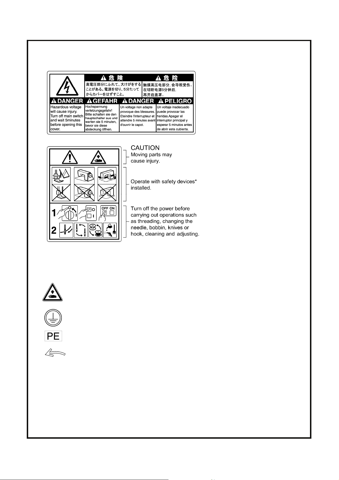
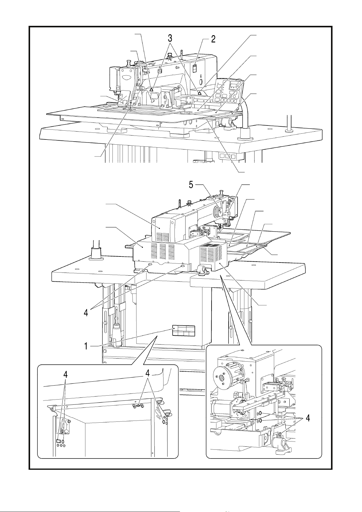
[3] Warning labels
The following warning labels appear on the sewing machine.
Please follow the instructions on the labels at all times when using the machine. If the labels have been removed or are
difficult to read, please contact your nearest Brother dealer.
1
2
*Safety devices
Devices such as eye guard, finger guard, thread take-up cover, motor cover, X motor cover,
tension release solenoid cover, inside cover, outside cover, middle cover, fixed cover and rear cover
3
Be careful to avoid getting hands caught in sliding parts.
4
5
Be sure to connect the ground. If the ground connection is not secure, you run a high risk of receiving
a serious electric shock, and problems with correct operation may also occur.
Direction of operation
iv
BAS-342G PS
Page 7
r
r
r
Rear cove
Rear cover
Thread take-up cover
Inside cover R
Middle cover
Eye guard
Finger guard
Motor cover
Rear cove
Outside cover
Fixed cover
Tension release solenoid cover
Inside cover L
Middle cove
Outside cover
Fixed cover
X motor cover
2740B
BAS-342G PS
v
Page 8

CONTENTS
1. NAMES OF MAJOR PARTS ................ 1
2. USEFUL FUNCTIONS
FOR OPTIMUM SEWING ..................... 2
3. TABLE PROCESSING DIAGRAM ....... 3
4. INSTALLATION.................................... 4
4-1. Removing the machine head fixing bolts [1]..... 4
4-2. Installing the control box [2].............................. 5
4-3. Installing the oil pan and support lever base.... 6
4-4. Installing the machine head.............................. 6
4-5. Tilting back and returning the machine head ... 7
4-6. Installing the gas spring.................................... 8
4-7. Installing the operation panel [3]....................... 9
4-8. Installing the solenoid valve assembly .............10
4-9. Connecting the air tubes [4].............................. 10
4-10. Installing the air hose [5]................................. 10
4-11. Adjusting the air pressure [6].......................... 11
4-12. Adjusting the speed controller [7] ................... 11
4-13. Connecting the cords [8]................................. 12
4-14. Connecting the ground wire [9] ...................... 14
4-15. Securing the cords and air tubes [10]............. 15
4-16. Installing the eye guard [11] ...........................16
4-17. Installing the cotton stand [12]........................ 16
4-18. Lubrication [13] ............................................... 17
4-19. Connecting the power cord [14] ..................... 18
4-20. Checking the safety switch [15] ...................... 18
6. USING THE OPERATION PANEL
(BASIC OPERATIONS) .......................26
6-1. Name and function of each operation
panel item..........................................................26
6-2. Loading sewing data .........................................28
6-3. Setting the program number .............................28
6-4. Setting the X-scale and Y-scale........................29
6-5. Setting the sewing speed..................................29
6-6. Checking the sewing pattern.............................30
6-7. Setting the height of the intermittent presser foot...31
6-8. Notes on handling CF cards (sold separately) ...32
7. SEWING ...............................................33
7-1. Sewing ..............................................................33
7-2. Using the STOP switch .....................................34
7-3. Using the thread wiper switch...........................34
Document CD ...........................................36
5. PREPARATION BEFORE SEWING.....19
5-1. Installing the needle.......................................... 19
5-2. Operating the 2-pedal foot switch..................... 19
5-3. Threading the upper thread .............................. 20
5-4. Winding the lower thread..................................22
5-5. Installing the bobbin case................................. 23
5-6. Thread tension.................................................. 24
5-6-1. Lower thread tension.............................. 24
5-6-2. Upper thread tension.............................. 24
5-7. Home position detection ................................... 25
BAS-342G PS
Page 9
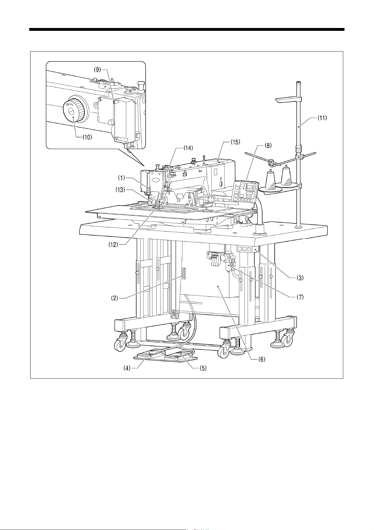
1. NAMES OF MAJOR PARTS
(1) STOP switch
(2) CF slot (12) Finger guard
(3) Power switch (13) Eye guard
(4) Work clamp switch (14) Thread take-up cover
(5) Start switch (15) Motor cover
(6) Control box
(7) Solenoid valve
(8) Operation panel
(9) Thread wiper switch
(10) Pulley
(11) Cotton stand
TM
CF
is a trademark of SanDisk Corporation.
Safety devices:
1. NAMES OF MAJOR PARTS
2741B
BAS-342G PS
1
Page 10
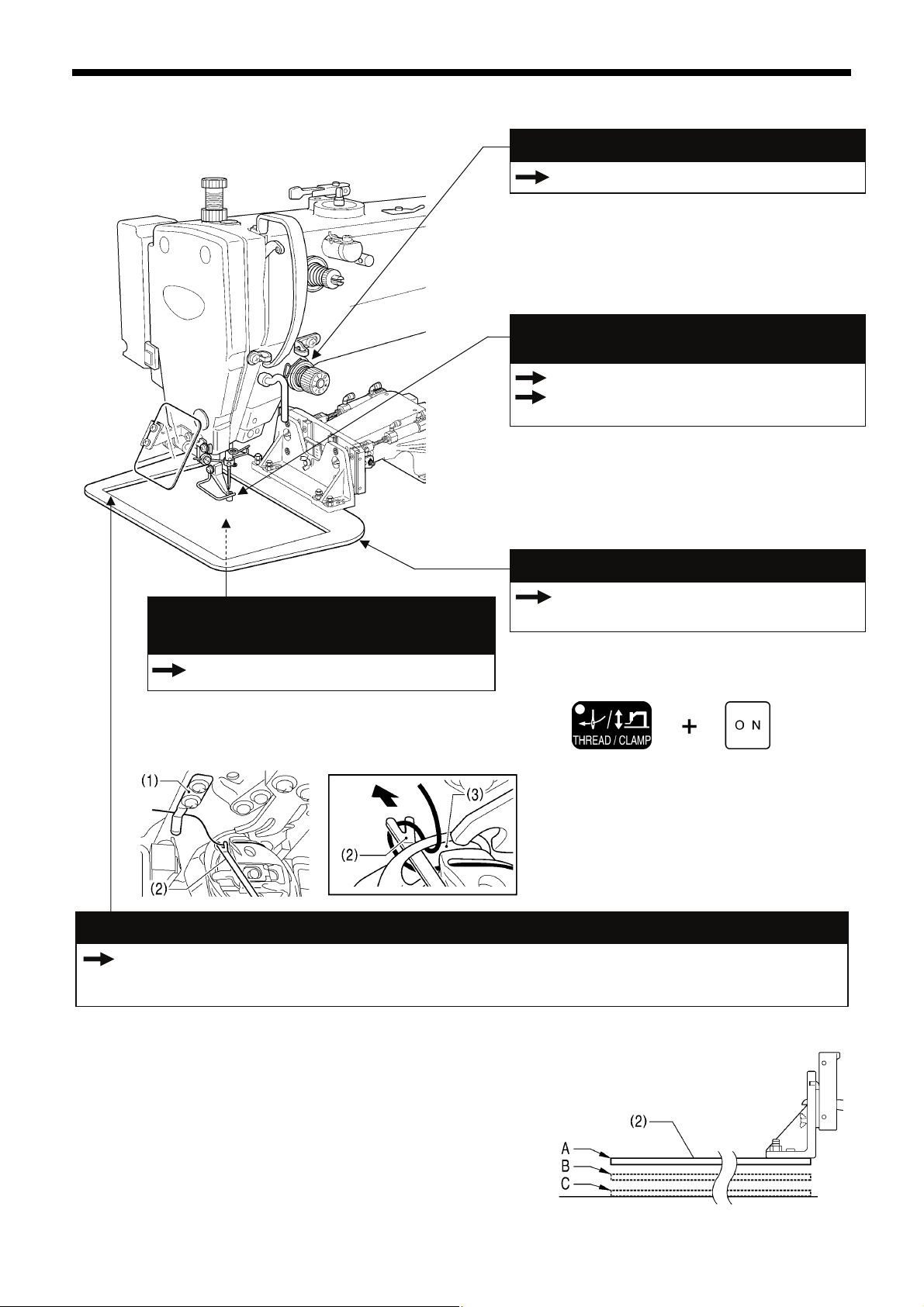
2. USEFUL FUNCTIONS FOR OPTIMUM SEWING
2. USEFUL FUNCTIONS FOR OPTIMUM SEWING
Easy threading in threading mode
Page 21
When using threading mode for threading, the tension
discs will open so that the thread can be threaded
more easily.
Furthermore, threading mode is safe because the
sewing machine will not start even when the foot
switch is depressed.
Intermittent presser foot height can be set easily
using the panel
Page 31
INSTRUCTION MANUAL CD
7-7. Using user programs
The height of the intermittent presser foot can be set
simply by entering a numeric value at the panel,
without the need for tools.
Furthermore, you can use user programs to set the
intermittent presser foot height to the desired height
separately for each sewing program.
Easy and accurate feed plate replacement
INSTRUCTION MANUAL CD
The lower thread can be easily threaded
using the threading bar
Page 23
If you clamp the lower thread in the thread hold
spring (1) and then push it gently using the threading
bar (2), you can make the lower thread pass easily
through the window (3) of the inner rotary hook.
Two types of work clamp dropping operation
INSTRUCTION MANUAL CD 5-8. Setting 2-step operation for the work clamp
7-2. Setting memory switches
7-3. List of memory switch settings
11-10-1. Installing the feed plate
The feed plate installation position can be obtained
accurately by using the panel, which makes feed
plate replacement much easier.
Feed plate installation mode
2919B
2920B
You can select one of two different types of dropping operation for
the work clamp (2) by changing memory switch settings.
<Work clamp dropping in one step>
When the work clamp switch is depressed, the work clamp (2)
drops in one movement from its highest position A to its lowest
position C.
<Work clamp dropping in two steps>
1. When the work clamp switch is depressed to the 1st step, the
work clamp (2) drops from its highest position A to the
intermediate position B.
2. When the work clamp switch is then depressed to the 2nd
step, the work clamp (2) drops to its lowest position C.
2
BAS-342G PS
4057M
Page 11
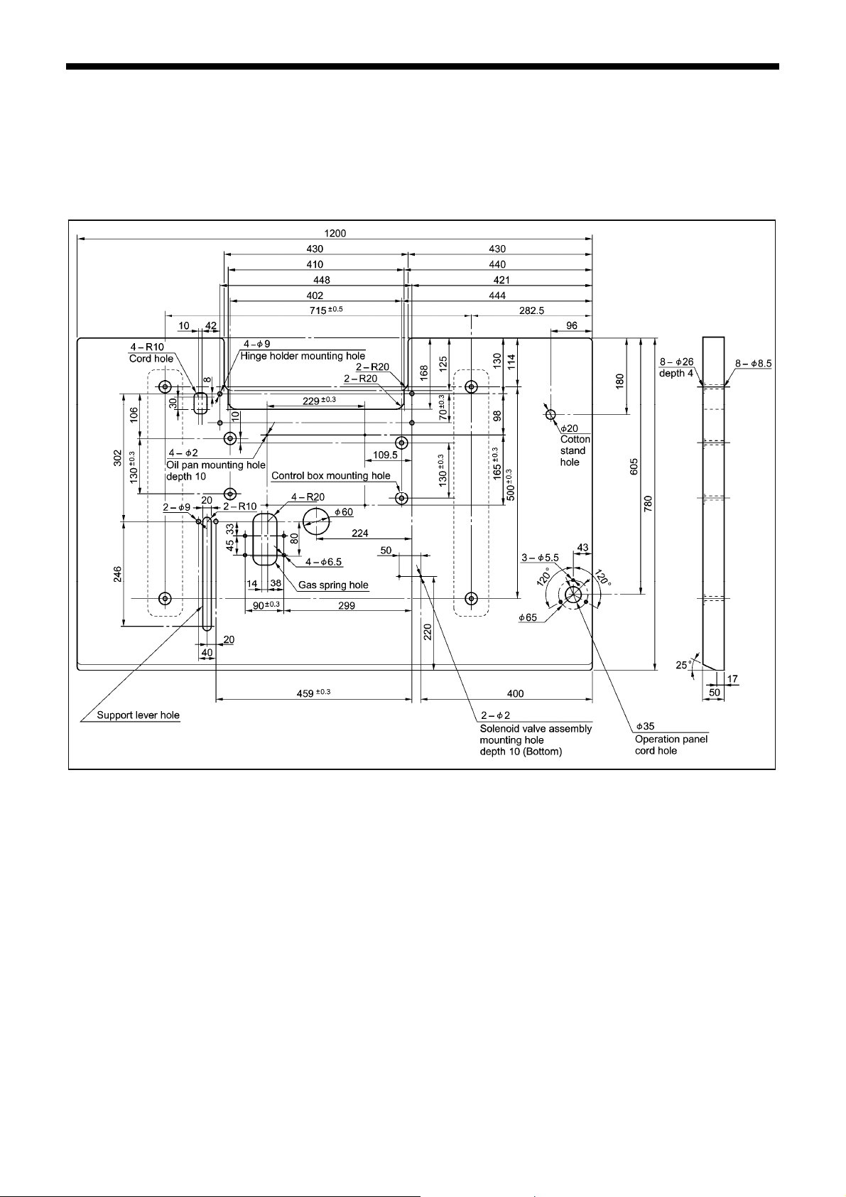
3. TABLE PROCESSING DIAGRAM
M
3. TABLE PROCESSING DIAGRAM
• The thickness of the table should be at least 50 mm, and it should be strong enough to bear the weight and vibration of the
sewing machine.
• If using casters, use ones which can bear the total weight of sewing machine and table.
• Check that the control box is at least 10 mm away from the leg. If the control box and the leg are too close together, it may result
in incorrect sewing machine operation.
4053
BAS-342G PS
3
Page 12
4. INSTALLATION
4. INSTALLATION
CAUTION
Machine installation should only be carried out by a
qualified technician.
Contact your Brother dealer or a qualified electrician for
any electrical work that may need to be done.
The sewing machine head weighs approximately 160
kg.
Use equipment such as a crane or hoist when installing
the machine head and adjusting the height of the table.
If you try to lift the machine head yourself, it may cause
injuries such as back injury.
Do not connect the power cord until installation is
complete.
If the foot switch is depressed by mistake, the sewing
machine might start operating and injury could result.
If using a work table which has casters, the casters
should be secured in such a way so that they cannot
move.
Use a table with a height of 84 cm or less. If the table is
too high, the machine head may become unbalanced
and fall down, and serious injury or damage to the
sewing machine may result.
When placing the sewing machine on the table
Hold the machine head with both hands when tilting it
back or returning it to its original position.
In addition, do not subject the machine head to extra
force while it is tilted back. If this is not observed, the
machine head may become unbalanced and fall down,
and serious injury or damage to the sewing machine
may result.
All cords should be secured at least 25 mm away from
any moving parts. Furthermore, do not excessively bend
the cords or secure them too firmly staples, otherwise
there is the danger that fire or electric shocks could
occur.
Be sure to connect the ground. If the ground connection
is not secure, you run a high risk of receiving a serious
electric shock, and problems with correct operation may
also occur.
Install the safety covers to the machine head and motor.
Carry out the procedure starting from "4-2. Installing the control box" on the next page.
If the sewing machine was already installed to the table when it was delivered
Carry out the procedures indicated by [1] to [15] in the titles in the order of the numbers.
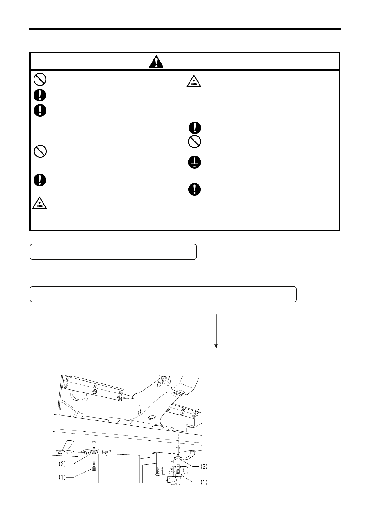
4-1. Removing the machine head fixing bolts [1]
If the sewing machine was already
installed to the table when it was
delivered, remove the two machine head
fixing bolts (1) and the two plain washers
(2).
2742B
4
BAS-342G PS
Page 13
M
4-2. Installing the control box [2]
CAUTION
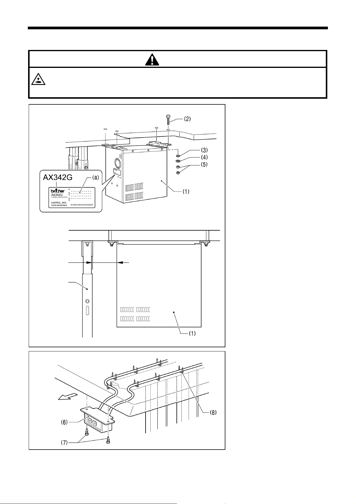
The control box is heavy, so installation should be carried out by two or more people.
In addition, take steps to make sure that the control box does not fall down.
If this is not done, injury to feet or damage to the control box may result.
4. INSTALLATION
3961
10mm or more
Operator
Leg
3962M
3963M
Before installing the control box (1), check
that the model plate (a) on the control box
(1) is “AX342G” to indicate that it is an
RX-control box for BAS-342G sewing
machines.
* If the sewing machine is installed to the
table, tilt back the machine head.
(Refer to "4-5. Tilting back and returning
the machine head".)
(1) Control box
(2) Bolts [4 pcs.]
(3) Plain washers [4 pcs.]
(4) Spring washers [4 pcs.]
(5) Nuts [8 pcs.]
NOTE:
Check that the control box (1) is at
least 10 mm away from the leg. If the
control box (1) and the leg are too
close together, it may result in
incorrect sewing machine operation.
(6) Power switch
(7) Wood screws [2 pcs.]
(8) Staples [7 pcs.]
NOTE:
Take care when tapping in the staples
(8) to make sure that they do not
pierce the power cord.
BAS-342G PS
5
Page 14
4. INSTALLATION
B
4-3. Installing the oil pan and support lever base
Table
3964M
(1) Oil pan
(2) Wood screws [4 pcs.]
(3) Oiler
(4) Support lever base
(5) Plain washers [2 pcs.]
(6) Spring washers [2 pcs.]
(7) Bolts [2 pcs.]
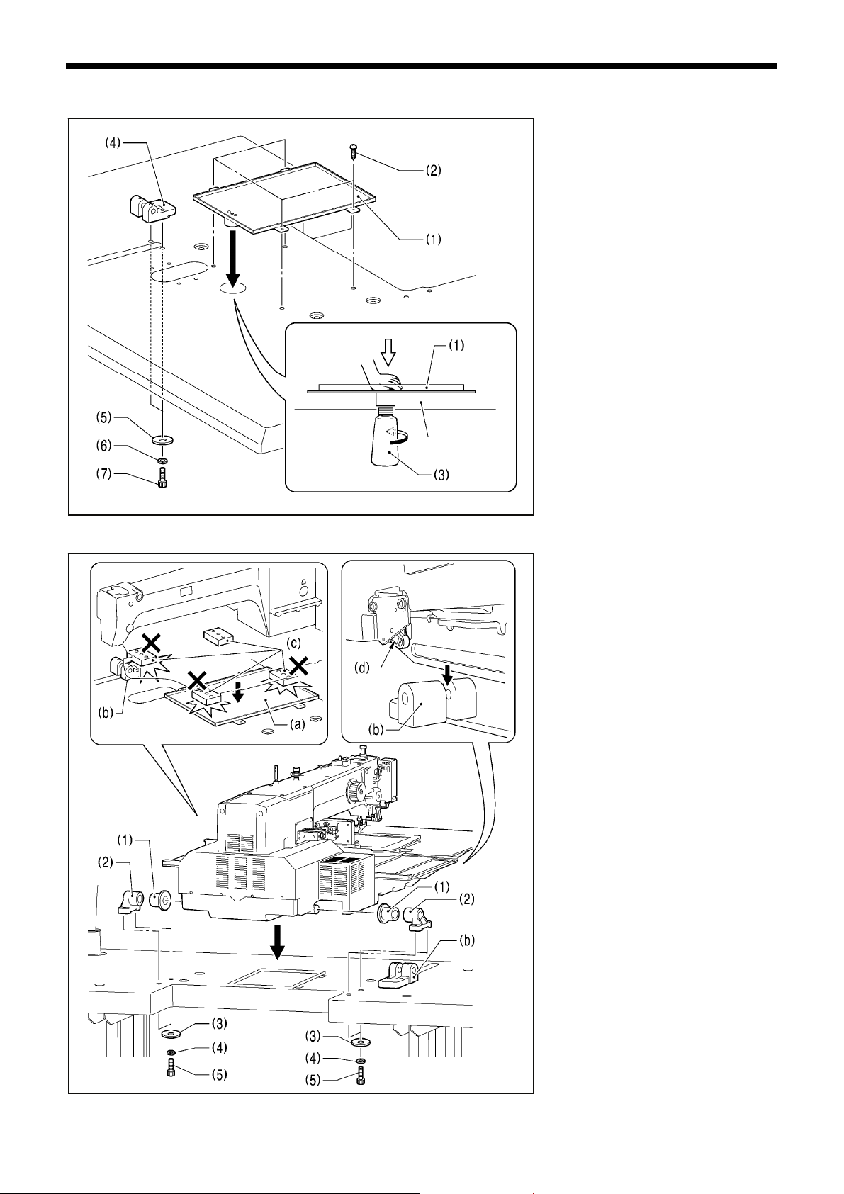
4-4. Installing the machine head
2743
1. Place the machine head onto the
table.
NOTE:
• Use a crane or hoist to install the
sewing machine.
• Be careful of the following when
lowering the machine head onto the
table.
! Do not let any cords get clamped
between the machine head and
the table.
! Do not place the machine head
cushion (c) on top of the oil pan
(a) or the support lever base (b).
! Do not let the side (d) of the
safety switch lever touch the
support lever base (b).
(1) Rubber bushes (2 pcs.)
(2) Hinge holders (2 pcs.)
(3) Plain washers [4 pcs.]
(4) Spring washers [4 pcs.]
(5) Bolts [4 pcs.]
(Continued on next page)
6
BAS-342G PS
Page 15

4. INSTALLATION
M
2. After placing the machine head onto the table, remove the
bolt (6) and the spacer (7).
The bolt (6) and the spacer (7) are necessary for
*
securing the support lever (8) when the machine head is
removed from the table, so keep them in a safe place.
3. Pass the support lever shaft (9) through the hole in the
support lever base (10) and through the groove (f) in the
support lever (8), and push it in until it is flush with the
surface of the support lever base (10).
If it is difficult to pass the support lever shaft (9) through
*
the groove (f) in the support lever (8), move the end of
the support lever (8) up and down while passing the
support lever shaft (9) through.
Flush
3966
4-5. Tilting back and returning the machine head
CAUTION
Hold the machine head with both hands when tilting it back or returning it to its original position.
In addition, do not subject the machine head to extra force while it is tilted back. If this is not observed, the machine head
may become unbalanced and fall down, and serious injury or damage to the sewing machine may result.
Always be sure to engage the stopper of the support lever (1) when tilting back the machine head.
If the stopper is not engaged, the machine head may return to its original position and your hands may get caught and
injury may result.
When disengaging the stopper, hold it by the knob (a).
If you hold at the place indicated by (b), your hand will get caught between the support lever (1) and the table when the
machine head is returned to its original position and injury will result.
Disengaging
the stopper
Engaging
the stopper
The machine head can be tilted
back and returned to one of three
heights.
3967M
BAS-342G PS
7
Page 16

4. INSTALLATION
4-6. Installing the gas spring
2744B
1. Tilt back the machine head, and then secure the support lever (1) at stopper position (a).
Refer to "4-5. Tilting back and returning the machine head".)
(
NOTE: Use equipment such as a crane or hoist to tilt back the machine head.
2. Tighten the two set screws (2) to secure the support lever shaft (3).
Crane or hoist
Engaging
the stopper
Disengaging
the stopper
Be sure to install so that
the side with “UP” on it is
facing upward.
Note that the L and R
shapes are different.
2915B
3. Install the gas spring (8).
(4) Gas spring holders [L and R]
(5) Spacer
(6) Bolt
(7) Nut
(8) Gas spring
(9) Shaft collars [2 pcs.]
(10) Gas spring shaft D
(11) Plain washers [2 pcs.]
(12) Retaining rings E [2 pcs.]
(13) Bolts [4 pcs.]
(14) Plain washers [4 pcs.]
(15) Spring washers [4 pcs.]
(16) Nuts [4 pcs.]
(17) Gas spring shaft U
(18) Set screw
After installing the gas spring (8), gently
*
return the machine head to its original
position.
(
returning the machine head".)
Refer to "4-5. Tilting back and
8
BAS-342G PS
Page 17

M
4-7. Installing the operation panel [3]
3970
< If the sewing machine was already installed to the table when it was delivered >
3971M
4. INSTALLATION
(1) Cushion A
(2) Operation panel base
(3) Plain washers (medium) [3 pcs.]
(4) Bolts [3 pcs.]
(5) Cushions B [3 pcs.]
(6) Plain washers (large) [3 pcs.]
(7) Nuts [6 pcs.]
* Tighten until the thickness of
cushion B (5) is about 1 mm.
(8) Rubber seat
(9) Operation panel stand
(10) Operation panel
* Pass the cords of the operation
panel (10) through the operation
panel stand (9) and under the
table.
(11) Bolts [3 pcs.]
(12) Bolt
(1) Operation panel
(2) Bolts [3 pcs.]
* Pass the cords of the operation
panel (1) through the operation
panel stand (3) and under the
table.
BAS-342G PS
9
Page 18

4. INSTALLATION
B
4-8. Installing the solenoid valve assembly
4-9. Connecting the air tubes [4]
Plugs 4
Branch unions Y
Connect as shown in
the illustration while
checking the marks.
2745B
Install underneath the work table. (Refer
to "3. Table processing diagram" for the
installation positions.)
(1) Solenoid valve assembly
(2) Washers [2 pcs.]
(3) Wood screws [2 pcs.]
NOTE:
Make sure that the solenoid valve
assembly does not touch the control
box or the leg of the table.
2746B
4-10. Installing the air hose [5]
1. Close the cock (1).
Close
Open
2747
10
BAS-342G PS
2. Turn the nut (3) at the end of the air hose (2) and connect it
to the valve (4).
3. Open the cock at the compressor.
* Check that no air is leaking from the connection of the
valve (4) and air hose (2).
4. Open the cock (1).
(The meter pointer will turn clockwise.)
NOTE:
Turn the cock (1) gently to open it.
5. Adjust the air pressure. (Refer to the next page.)
Page 19

B
B
4-11. Adjusting the air pressure [6]
2748
4-12. Adjusting the speed controller [7]
Upper knob
Lower knob
Val ve 3
Val ve 2
4. INSTALLATION
Lift up the handle (2) of the regulator (1) and then turn it to
adjust the air pressure to 0.5 MPa.
After adjustment is complete, push the handle (2) downward to
lock it.
< Adjusting the lifting and lowering speeds for the work
clamp >
You can adjust the lifting and lowering speeds for the work
clamp using the knobs on valves 1 and 2.
• When the upper knob is tightened, the lifting speed becomes
slower. When it is loosened, the lifting speed becomes faster.
• When the lower knob is tightened, the lowering speed
becomes slower. When it is loosened, the lowering speed
becomes faster.
Reference adjustments
Val ve 1
Val ve 2
Upper knob Fully tighten
Lower knob
Upper knob
Lower knob Fully tighten
Fully tighten and then loosen by
8 turns
Fully tighten and then loosen by
5 turns
Val ve 1
2749
You can operate the work clamp when the power is turned off
by pressing the manual buttons (1).
< Adjusting the speed of the thread trimming air cylinder >
Valve 3 is used for adjusting the speed of the thread trimming
air cylinder. To use, fully tighten both the upper and lower knobs,
and then loosen them both by 6 turns.
* If the knobs are not at the tightening settings mentioned
above, upper thread trimming may not work correctly.
BAS-342G PS
11
Page 20

4. INSTALLATION
M
4-13. Connecting the cords [8]
<Main P.C. board>
3977
1. Remove the cover of the control box.
2. Loosen the two screws (1), and then
open the cord presser plate (2) in the
direction of the arrow.
3. Pass the bundle of cords from the
machine head through the hole in the
table, and then pass it through the
hole in the control box together with
the following cords.
• Tow-pedal foot switch (3)
• Operation panel (Do not pass the
ground wires through the hole.)
• Solenoid valve assembly
4. Securely connect the connectors as
indicated in the table below.
NOTE:
• Check that the connector is facing the
correct way, and then insert it firmly
until it locks into place.
• Secure the cables with cable ties and
cord clamps, while being careful not to
pull on the connector.
* Be sure to make the ground connection.
(Refer to "4-14. Connecting the ground
wire".)
X pulse motor encoder 5-pin white P20 (X-ENC) (3)
Y pulse motor encoder 5-pin blue P4 (Y-ENC) (3)
Intermittent presser foot pulse motor encoder 5-pin black P5 (P-ENC) (3)
Foot switch 10-pin P6 (FOOT) (3)
Operation panel 8-pin P1 (PANEL) (3)
Safety switch 3-pin P9 (HEAD-SW) (4)
Home position sensor assembly 12-pin P8 (SENSOR1) (4)
STOP switch 6-pin P13 (HEAD) (4)
Valve harness 12-pin P12 (AIR1) (4)
Programmer relay harness 8-pin P7 (PRG) (3)
Fan 6-pin P10 (SENSOR2) (4)
Solenoid selection harness 4-pin P3 (CUTTER)
2916B
12
Thread trimming cylinder sensor harness 16-pin P23 (EX-IN1) (4)
Connector
BAS-342G PS
Connection location on
main P.C. board
Lock the cord
clamp securely.
Cord clamp
-
(Continued on next page)
Page 21

<Power supply motor P.C. board>
<PMD P.C. board>
Machine head memory 7-pin P3 (HEAD-M) (4)
Upper shaft motor 3-pin P4 (UVW) (5)
Synchronizer 14-pin P5 (SYNC) (5), (6)
Work clamp pulse motor 4-pin black P3 (PPM) (5), (6)
Thread trimmer solenoid 6-pin P6 (SOL1) (5), (6)
Tension release solenoid 4-pin P7 (SOL2) (5), (6)
Y pulse motor 4-pin blue P8 (YPM) (5), (6)
X pulse motor 4-pin white P10 (XPM) (5), (6)
2568B
Connector
Connector
4. INSTALLATION
<Removing>
<Securing>
NOTE:
Route the X, Y and work clamp pulse motor
harnesses so that they do not touch the
PMD P.C.
* Be sure to make the ground connection.
(Refer to "4-14. Connecting the ground
wire".)
Connection location on
power supply motor P.C.
board
Connection location on
PMD P.C. board
Cord clamp/cable tie
Cable tie
Press
the tab.
BAS-342G PS
13
Page 22

4. INSTALLATION
B
4-14. Connecting the ground wire [9]
CAUTION
Be sure to connect the ground. If the ground connection is not secure, you run a high risk of receiving a serious electric
shock, and problems with correct operation may also occur.
(1) Ground wire from upper shaft motor harness
(2) Ground wire from the machine head
(3) Ground wire from operation panel
(4) Ground wires from two-pedal foot switch harnesses (2 wires)
NOTE: Make sure that the ground connections are secure in order to ensure safety.
2750
14
BAS-342G PS
Page 23

4-15. Securing the cords and air tubes [10]
<Seen from underneath table>
Leg
Control box
Table
Operation panel
Solenoid valve
assembly
2751B
3982M
4. INSTALLATION
Secure the three air tubes (a), the
solenoid valve assembly cord (b) and the
operation panel cord (c) together
underneath the table with the three cord
holders (1).
(1) Cord holders [3 pcs.]
(2) Wood screws [3 pcs.]
Checking the cords>
<
1. Gently tilt back the machine head.
(
Refer to "4-5. Tilting back and
returning the machine head".
2. Check that none of the cords are
being pulled.
3. Return the machine head to its
original position.
4. Close the cord presser plate (3) in the
direction of the arrow, and secure it by
tightening the two screws (4).
NOTE:
Close the cord presser plate (3)
securely so that no foreign objects,
insects or small animals can get
inside the control box.
5. Secure the cover of the control box by
tightening the eight screws (5).
Check that the cords are not clamped
by the cover at this time.
)
BAS-342G PS
15
Page 24

4. INSTALLATION
M
4-16. Installing the eye guard [11]
Attach all safety devices before using the sewing machine.
If the machine is used without these devices attached, injury may result.
CAUTION
(1) Screw (loosen)
(2) Eye guard (tilt forward)
(3) Eye guard assembly
(4) Plain washers [2 pcs.]
(5) Screws [2 pcs.]
After installing the eye guard assembly
(3), return the eye guard (2) to its original
angle, and then tighten the screw (1) to
secure it in place.
2367B
4-17. Installing the cotton stand [12]
3983
(1) Cotton stand
NOTE:
Fit the washer (2), and then securely
tighten the nut (3) so that the cotton
stand does not move.
16
BAS-342G PS
Page 25

4-18. Lubrication [13]
Do not connect the power cord until lubrication is complete.
If the foot switch is depressed by mistake, the sewing machine might start operating and injury could result.
Be sure to wear protective goggles and gloves when handling the lubricating oil and grease, so that they do not get into
your eyes or onto your skin. If the oil and grease get into your eyes or onto your skin, inflammation can result.
Furthermore, do not drink or eat the lubricating oil or grease. They may cause diarrhea or vomiting.
Keep the oil out of the reach of children.
CAUTION
• The sewing machine should always be lubricated and the oil
supply replenished before it is used for the first time, and
also after long periods of non-use.
• Use only the lubricating oil <JX Nippon Oil & Energy
Corporation Sewing Lube 10N; VG10> specified by Brother.
* If this type of lubricating oil is difficult to obtain, the recommended
oil to use is <Exxon Mobil Essotex SM10; VG10>.
1. Fill the arm oil tank and the bed oil tank with oil.
NOTE:
Be sure to add more oil when the oil level drops down
to about one-third full in the oil gauge window (1). If the
oil drops below the one-third full level in the oil gauge
window (1), there is the danger that the sewing
machine may seize during operation.
2. Remove the bobbin case and add 2-3 drops of oil to the
rotary hook race (2).
4. INSTALLATION
2752B
2753B
3986M
3. If using the needle cooler (3), fill it with silicon oil (100
BAS-342G PS
2
/s).
mm
(Refer to "5-3. Threading the upper thread" for details on
using the needle cooler (3).)
17
Page 26

4. INSTALLATION
4-19. Connecting the power cord [14]
CAUTION
Be sure to connect the ground. If the ground connection is not secure, you run a high risk of receiving a serious electric
shock, and problems with correct operation may also occur.
<Single-phase
specifications>
1. Attach an appropriate plug to the power cord (1). (The
green and yellow wire is the ground wire.)
2. Insert the plug into a properly-grounded AC power supply.
* The inside of the control box uses single-phase power.
NOTE:
• If the ground connection is not secure, electric shocks,
operating errors or damage to electronic components
such as P.C. boards may occur.
• Do not use an extension cord. If this is not observed, it
may cause problems with correct operation.
<Three-phase
specifications>
Green and yellow wire
(ground wire)
Green and yellow wire
(ground wire)
3988M
4-20. Checking the safety switch [15]
1. If the machine head is tilted back, gently return it to its
original position.
the machine head".
2. Turn on the power switch.
3. Check that no error numbers are displayed on the operation
panel.
(Refer to "4-5. Tilting back and returning
)
<
If error [E050], [E051] or [E055] is displayed >
If the safety switch (1) is not turned on, error [E050], [E051] or
[E055] will occur.
Check the installation position of the safety switch (1).
1. Turn off the power switch.
2. Loosen the two screws (2).
3. Push down the right side of the safety switch (1) so that the
safety switch (1) turns on, and then tighten the two screws
(2).
4. Turn on the power and check that no error numbers are
displayed.
18
3989M
BAS-342G PS
Page 27

5. PREPARATION BEFORE SEWING
5-1. Installing the needle
CAUTION
Turn off the power switch before installing the needle.
If the foot switch is depressed by mistake, the sewing machine might start operating and injury could result.
1. Loosen the set screw (1).
2. Insert the needle (2) as far as it will go with the
hollow (3) facing to the front, and then securely
tighten the set screw (1). [Figure A]
<If hitch stitches appear in one direction during
square sewing>
1. Loosen the set screw (1).
2. Insert the needle (2) as far as it will go so with
the hollow (3) facing to the front and so that it’s
angle matches the angle of reference line (4),
and then securely tighten the set screw (1).
[Figure B]
* If the installation angle of the needle has been
changed, be sure to readjust the needle
clearance. (Refer to “11-6. Adjusting the needle
2754B
Front Front
clearance” in the instruction manual CD.)
5. PREPARATION BEFORE SEWING
5-2. Operating the 2-pedal foot switch
3991M
Work clamp switch
Start switch
2755B
When the work clamp switch (left side) is depressed, the
intermittent presser foot (1) and the work clamp (2) are
lowered, and when the start switch (right side) is then
depressed, the sewing machine starts operating.
*
The work clamp (2) lowering method can be changed
using memory switch No. 002. (Refer to "7-3. List of
memory switch settings" in the instruction manual CD.)
BAS-342G PS
19
Page 28

5. PREPARATION BEFORE SEWING
5-3. Threading the upper thread
Thread the upper thread correctly as shown in the illustration below.
* When using threading mode for threading, the tension discs (1) will open so that the thread can be threaded more easily.
(Refer to following page.)
[If using cotton thread or spun thread]
[If using synthetic thread]
Thread the upper thread
Needle cooler
2756B
• Turn the machine pulley (2) and raise the thread take-up (3) to its highest position before threading the upper thread.
(This will make threading easier and it will prevent the thread from coming out at the sewing start.)
• When threading the thread through the needle, allow a distance of approximately 45 mm between the needle hole and the
end of the thread.
If the trailing length of the thread is too long, it may cause the thread to become tangled.
2572B
2757B
20
BAS-342G PS
Page 29

5. PREPARATION BEFORE SEWING
<Threading mode>
Threading mode is safe because the sewing machine will not start even when the foot switch is depressed.
1
2
All indicators switch off
THREAD/CLAMP indicator illuminates
MENU indicator switches off
Threading the thread.
3
• When 5 minutes have passed, the buzzer will sound and the tension discs will close.
* When memory switch No. 564 is set to "2", the buzzer will sound after one minute has elapsed, and the tension
discs will close.
Ending threading mode
4
THREAD/CLAMP indicator switches off
Turn on the power switch.
Press the THREAD/CLAMP key.
• The work clamp and the intermittent presser foot will be
lowered.
• The tension discs will open.
Press the THREAD/CLAMP key.
• The work clamp and the intermittent presser foot will
return to the position they were at before threading mode
began.
4421Q
4427Q
BAS-342G PS
21
Page 30

5. PREPARATION BEFORE SEWING
5-4. Winding the lower thread
CAUTION
Do not touch any of the moving parts or press any objects against the machine while winding the lower thread.
Injury or damage to the sewing machine may result.
2759B
2760B
2775B
More thread
Less thread
For case A
For case B
2758B
1. Place the bobbin onto the bobbin winder shaft (1).
2. Thread the thread as shown in the illustration, wind the
thread around the bobbin several times, and then press
the bobbin presser arm (2).
3. Turn on the power switch.
4. Depress the work clamp switch (3) to lower the work
clamp, and then depress the start switch (4). (Home
position detection will be carried out.)
5. Check that the needle is not touching the work clamp.
6. Depress the work clamp switch (3) to lower the work
clamp.
7. While pressing the TENSION/WIND key (5), depress the
start switch (4).
8. Release the TENSION/WIND key (5) after the machine
starts operating, and keep depressing the start switch (4)
until the lower thread stops being wound onto the bobbin.
(If you release the start switch (4) while this operation is
in progress, hold down the TENSION/WIND key (5) and
then depress the start switch (4) to restart winding of the
thread.)
9. Once winding of the set amount of lower thread (80 - 90%
of the bobbin capacity) is completed, the bobbin presser
arm (2) will return automatically.
10. Remove the bobbin, hook the thread onto the knife (6),
and then pull the bobbin in the direction of the arrow to
3997M
cut the thread.
3999M
Adjusting the bobbin winding amount
Loosen the screw (7) and move the bobbin presser (8) to
adjust.
If the thread winds onto the bobbin unevenly
Loosen the set screw (9) and move the bobbin winder
tension assembly (10) up and down to adjust.
* For case A, move the bobbin winder tension assembly
(10) down, and for case B, move it upward.
22
BAS-342G PS
Page 31

5. PREPARATION BEFORE SEWING
5-5. Installing the bobbin case
CAUTION
Turn off the power switch before installing the bobbin case.
If the foot switch is depressed by mistake, the sewing machine might start operating and injury could result.
2761B
1873B
1. Pull the hook cover (1) downward to open it.
2. While holding the bobbin so that the thread winds to the right, insert the bobbin into the bobbin case.
3. Pass the thread through the thread slot (2), pass it underneath the spring (3), and then pass it through the thread guide (4),
leaving a trailing-out length of about 35 mm.
4. Hold the latch on the bobbin case and insert the bobbin case into the rotary hook.
5. Clamp the lower thread in the thread hold spring (5).
6. Use the threading bar (6) to pass the thread through the window of the inner rotary hook. (The thread will be released from
the thread hold spring (5).)
1897B
1874B
BAS-342G PS
23
Page 32

5. PREPARATION BEFORE SEWING
5-6. Thread tension
[Thread tension reference]
Upper thread #20 or similar
Lower thread #20 or similar
Upper thread tension (N)
Lower thread tension (N)
Pre-tension (N)
Needle DP x 17 #19
Normal sewing speed 2,000 sti/min
1.0 − 1.6
0.4 − 0.6
0.3 − 0.6
5-6-1. Lower thread tension
Weaker
Stronger
5-6-2. Upper thread tension
Weaker
Weaker
Stronger
Stronger
1875B
2573B
Adjust the lower thread tension by turning the adjusting
screw (1).
1. Turn the tension nut (1) (main tension) to adjust the
tension as appropriate for the material being sewn.
2. Use the tension nut (2) (sub tension) to adjust the upper
thread trailing length to about 45 mm.
24
BAS-342G PS
Page 33

5-7. Home position detection
Aligned
2574B
2918B
4421Q
5. PREPARATION BEFORE SEWING
Before starting home position detection, check that the
needle bar is at the needle up stop position.
Turn the pulley (1) until the ridge at the bottom of the thread
take-up (2) is aligned with the { mark on the arm.
1. Turn on the power switch.
The POWER indicator (3) will illuminate, and the model
name [342] will appear in the PROGRAM No. display (4)
and [A-PS] will appear in the menu display (5).
After this, the program number will flash in the
PROGRAM No. display (4).
2. Depress the work clamp switch (6) to lower the work
clamp, and then depress the start switch (7). (After home
position detection is carried out, the work clamp will move
to the sewing start position and then it will rise.)
2762B
4007M
* For programs with a large number of stitches, the
buzzer will sound after the home position is detected,
and then the work clamp will move to the sewing start
position.
NOTE:
If error "E110" is displayed when the start switch (7) is
depressed, turn the pulley (1) in the direction of
operation to clear the error display.
4008M
BAS-342G PS
25
Page 34

6. USING THE OPERATION PANEL (BASIC OPERATIONS)
6. USING THE OPERATION PANEL
(BASIC OPERATIONS)
6-1. Name and function of each operation panel item
4435Q
(1) Power indicator
Illuminates when the power is turned on.
(2) CAUTION indicator
Illuminates when an error occurs.
(3) RESET key
Used to reset errors.
(4) TEST key
Used to start test mode.
(5) TEST indicator
Illuminates when the TEST key (4) has been pressed.
(6) THREAD/CLAMP key
Used to start threading mode or work clamp height setting mode.
(7) THREAD/CLAMP indicator
Illuminates when the THREAD/CLAMP key (6) has been pressed.
(8) TENSION/WIND key
Used to wind the lower thread.
(9) TENSION/WIND indicator
Used when the digital tension set (option) is installed.
26
BAS-342G PS
Page 35

6. USING THE OPERATION PANEL (BASIC OPERATIONS)
(10) X-SCALE indicator
Illuminates when the SELECT key (15) is pressed to shown the X-scale setting.
(11) Y-SCALE indicator
Illuminates when the SELECT key (15) is pressed to shown the Y-scale setting.
(12) SPEED indicator
Illuminates when the SELECT key (15) is pressed to shown the sewing speed setting.
(13) COUNTER indicator
Illuminates when the SELECT key (15) is pressed to shown the lower thread or production counter setting.
(14) SPLIT No. indicator
Illuminates when the SELECT key (15) is pressed to show the split setting when split data (for specifying a pause while
the program is running) exists.
(15) SELECT key
Used to select a menu (X-scale, Y-scale, sewing speed and counter).
(16) Menu display
Displays information such as menu setting values, memory switch settings and error codes.
(17) Setting keys
Used to change the value which is displayed in the menu display (16).
In addition, it is used to move the needle position forward and back when sewing has been paused.
(18) PROGRAM No. display
Displays information such as program numbers.
(19) Setting keys
Used to change the value which is displayed in the PROGRAM No. display (18).
(20) CF media indicator
Illuminates when a CF card (external media) is inserted while the power is turned on.
(21) FD media indicator
Illuminates when the FDD set (option) is connected.
(22) Function keys [F1, F2, F3, F4]
Used to select user programs and to set and select cycle programs.
(23) R/W key
Used to read data from and write data to external media.
CFTM is a trademark of SanDisk Corporation.
BAS-342G PS
27
Page 36

6. USING THE OPERATION PANEL (BASIC OPERATIONS)
6-2. Loading sewing data
Refer to "6-8. Notes on handling CF cards (sold separately)" for details on using CF cards.
1
2
CF media indicator illuminates
3
Loading
Loading complete
4
The PROGRAM No. display will change from " P" to the selected program number.
Turn off the power switch, remove the CF card, and then close the cover of the CF slot.
With the power turned off, insert the CF card into the CF
slot.
NOTE:
• Make sure the CF card is facing the correct way
when inserting it.
• Always be sure to keep the cover closed except
when inserting and removing the CF card. If this is
not done, dust may get inside and cause problems
with operation.
Turn on the power switch.
Press the or key to select the program number
(100 − 999).
* The "---" display is used to check the feed home
position.
Press the R/W key.
• The buzzer will sound and the selected sewing data
will be loaded from the CF card and copied into the
sewing machine's internal memory.
4453Q
4421Q
4457Q
4498Q
6-3. Setting the program number
4012M
28
1. Press the or key (1) to select the program number
that is loaded into the internal memory.
• The program number will flash in the PROGRAM No.
display (2).
• "---" will appear at the time of shipment from the
factory. (For checking feed home position)
2. Depress the work clamp switch (3) to lower the work
clamp, and then depress the start switch (4).
• The work clamp will move to the sewing start position,
and then the program number will be applied.
• The program number will stop flashing and illuminate
steadily.
NOTE:
After completing the setting, be sure to refer to "6-6.
Checking the sewing pattern" to check that the needle
drop position is correct.
BAS-342G PS
Page 37

6-4. Setting the X-scale and Y-scale
4013M
6-5. Setting the sewing speed
6. USING THE OPERATION PANEL (BASIC OPERATIONS)
The scales are set to 100 (%) at the time of shipment from
the factory.
1. Press the SELECT key (1) so that the X-SCALE
indicator (2) (for X-scale setting) or the Y-SCALE
indicator (3) (for Y-scale setting) is illuminated.
• The setting value (%) will appear in the menu display
(4).
* When memory switch no. 402 is set to "ON", the
settings will be displayed in units of mm.
2. Press the
• The program number will flash in the PROGRAM No.
display (6).
3. Depress the work clamp switch (7) to lower the work
clamp, and then depress the start switch (8).
• The work clamp will move to the sewing start position,
and then the scales will be applied.
• The program number will stop flashing and illuminate
steadily.
NOTE:
After completing the setting, be sure to refer to "6-6.
Checking the sewing pattern" to check that the needle
drop position is correct.
The sewing speed is set to 2000 (sti/min) at the time of
shipment from the factory.
1. Press the SELECT key (1) until the SPEED indicator (2)
illuminates.
• The setting value (sti/min) will appear in the menu
display (3).
2. Press the
(Sewing speed setting: 400 − 2700)
or key (5) to set the scale (0 − 400).
or key (4) to set the sewing speed.
4956Q
BAS-342G PS
29
Page 38

6. USING THE OPERATION PANEL (BASIC OPERATIONS)
6-6. Checking the sewing pattern
Use test feed mode to check the needle movement with only the work clamp operating.
Check that the needle hole in the needle plate does not come out from the frame of the work clamp.
1
TEST indicator illuminates
2
COUNTER indicator illuminates
Starting continuous test feed mode
3
TEST indicator illuminates
TEST indicator switches off
If test feeding continues until the
4
final stitch, the work clamp will move
to the sewing start position and then
stop.
TEST indicator switches off
Press the TEST key.
Select the program number to be checked, and then set the X-scale and
the Y-scale.
• The program number will flash.
Depress the work clamp switch (1) to lower the work clamp, and then
depress the start switch (2).
• The work clamp will move to the sewing start position, and then the
program number will stop flashing and illuminate steadily.
• The number of stitches will appear in the menu display.
Depress the work clamp switch (1) to lower the work clamp, and then
depress and release the start switch (2).
• The work clamp will start moving continuously one stitch at a time.
[Fast-forward test mode]
If the work clamp switch (1) is depressed while the work clamp is moving,
the feeding speed can be increased while the work clamp switch (1) is
depressed.
When the
forward by one stitch, and when the
pressed, the work clamp will move backward by one
stitch. (It will move quicker if you keep the key pressed
down.)
key is pressed, the work clamp will move
4957Q 4014M
4014M
4443Q
key is
If you would like sewing to start while test feeding is in
progress, press the TEST key to switch off the TEST
indicator.
When the start switch (2) is depressed, sewing will
start.
4014M
Press the TEST key.
30
BAS-342G PS
Page 39

6. USING THE OPERATION PANEL (BASIC OPERATIONS)
6-7. Setting the height of the intermittent presser foot
You can use the operation panel to change the setting value for the intermittent presser foot height.
1
2
All indicators switch off
THREAD/CLAMP indicator illuminates
MENU indicator switches off
<Changing modes>
Ending setting mode
3
THREAD/CLAMP indicator switches off
Intermittent presser foot operation
During standby
When lowered
While sewing
Press the THREAD/CLAMP key.
The sewing machine will switch to threading mode.
• " 1" will appear in the PROGRAM No. display and the
intermittent presser foot (1) will drop.
Press the key.
The sewing machine will switch to intermittent presser foot height
setting mode.
• " 4" will appear in the PROGRAM No. display and the
intermittent presser foot (1) will rise to the setting value that
appears in the menu display.
(Intermittent presser foot height setting: 0.0 − 10.0)
Press the or key to set the intermittent presser foot
height.
• The intermittent presser foot (1) will be raised or lowered to the
height of the new value that has been set.
NOTE:
After making the setting, be sure to turn the pulley once by
hand and check that the intermittent presser foot (1) does not
touch the needle bar.
" 1" Threading mode
↑ ↓
" 4" Intermittent presser foot height setting mode
Press the THREAD/CLAMP key.
• The setting values will be memorized.
• The intermittent presser foot (1) will return to the status that it
was at before the sewing machine was switched to setting
mode.
1 Intermittent presser foot lift amount
2 Intermittent presser foot height
The settings can be made by the above
operations.
However, if the intermittent presser foot
height is set to a smaller setting than the
intermittent presser foot stroke, the
intermittent presser foot will not drop in
order to prevent it from coming into contact
with the needle plate.
3 Intermittent stroke
When making the adjustment, refer to
"11-13. Changing the intermittent stroke" in
the instruction manual CD.
4445Q
2158B
5225Q
4016M
2763B
BAS-342G PS
31
Page 40

6. USING THE OPERATION PANEL (BASIC OPERATIONS)
6-8. Notes on handling CF cards (sold separately)
• Use a CF card with a memory capacity of 32, 64, 128, 256, 512 MB, 1GB or 2GB.
(CF cards with a capacity of more than 2GB are not supported.)
• Do not disassemble or modify the CF card.
• Do not bend, drop or scratch CF cards or place heavy objects on top of them.
• Avoid contact with liquids such as water, oil, solvents or drinks.
• Use and store CF cards in locations that are free from strong static electricity and electrical interference.
• Do not use or store CF cards in places where they may be subject to vibrations or shocks, direct sunlight, high
temperature or humidity or strong magnetic fields from equipment such as speakers, or places which are dusty from thread
scraps, etc.
• Do not subject CF cards to shocks or impacts or remove them from the sewing machine while data is being loaded or
written.
• The data on the CF cards may become lost or corrupted due to some malfunction or accident. It is recommended that you
make a backup of important data.
• CF cards should only be removed after the power for the sewing machine has been turned off.
• CF cards are already formatted when they are purchased, and so you should not reformat them.
• The recommended CF cards are commercially-available ones from SanDisk or HAGIWARA SYS-COM. CF cards from
other manufacturers can be used, but different formatting methods may mean that loading from or writing to such cards
may not be possible.
For more information, refer to the documentation provided with the CF card.
* This product is compatible with CF cards that have been formatted using the FAT16 method. Cards that have been
formatted using the FAT32 method cannot be used.
* CFTM is a trademark of SanDisk Corporation.
* Company names and product names appearing in this manual are trademarks or registered trademarks of the
respective owners. However, no TM or other similar symbols appear in the main text of this manual.
32
BAS-342G PS
Page 41

7. SEWING
CAUTION
Turn off the power switch at the following times.
If the foot switch is depressed by mistake, the sewing machine might start operating and injury could result.
• When threading the needle
• When replacing the bobbin and needle
• When not using the machine and when leaving the machine unattended
Do not touch any of the moving parts or press any objects against the machine while sewing, as this may result in
personal injury or damage to the machine.
7-1. Sewing
4978Q
4020M
2764B
Use a work clamp and a feed plate which will hold the article securely so that it does not slip.
If using the standard work clamp and feed plate and the article being sewn is slipping, take measures to stop the work
clamp and feed plate from being slippery.
1. Turn on the power switch.
2. Press the
number that you would like to use.
* Refer to "6-2. Loading sewing data" for details on
reading sewing data from a CF card.
3. Depress the work clamp switch (2) to lower the work
clamp (3), and then depress the start switch (4).
• The work clamp will move to the sewing start
position.
• Home position detection will be carried out
immediately after the power switch is turned on.
4. Place the article to be sewn underneath the work clamp
(3).
5. Depress the work clamp switch (2).
• The work clamp (3) will drop.
6. Depress the start switch (4).
• The sewing machine will start sewing.
7. When sewing is complete, the thread will be trimmed
and the work clamp (3) will rise.
or key (1) to select the sewing program
7. SEWING
BAS-342G PS
33
Page 42

7. SEWING
7-2. Using the STOP switch
If you press the STOP switch (1) while sewing or test feeding is in progress, the CAUTION indicator (2) will illuminate and
the sewing machine will stop immediately.
2264B
4982Q
<Clearing>
1. Press the RESET key (3).
• The thread will be trimmed, and then the CAUTION
indicator (2) will switch off and the buzzer will stop
sounding.
2. If you do not wish to continue sewing, press the RESET
key (3) once more.
• The program number will flash. Carry out preparation
for the next sewing.
<Continuing sewing from a stopping point>
If you have pressed the STOP switch (1) at times such as if the thread breaks while sewing or the lower thread runs out, you
can resume sewing from the point where the thread ran out.
1
Press the RESET key.
• The thread will be trimmed, and then the CAUTION indicator will switch
off and the buzzer will stop sounding.
2
3
Press the key to return the work clamp to the position where sewing is
to be continued.
• When the
stitch, and when the
forward by one stitch. (It will move quicker if you keep the key pressed
down.)
Depress the start switch (4).
key is pressed, the work clamp will move backward by one
key is pressed, the work clamp will move
4443Q
• The sewing machine will start operating and sewing will start.
4022M
7-3. Using the thread wiper switch
The thread wiper switch (1) can be used to turn the thread
wiper (2) on and off.
34
4023M
BAS-342G PS
Page 43

MEMO
BAS-342G PS
35
Page 44

Document CD
For cleaning, standard adjustments and more details, please refer to the instruction
manual contained in the Document CD.
3168M
Contents of the Document CD
The following documents are contained in PDF format.
・ Basic Operation Manual
・ Instruction Manual
・ Parts Book
Recommended system configuration for using the Document CD
OS: Windows® XP Service Pack 2, Windows Vista®, Windows® 7
Browser version: Microsoft® Internet Explorer 6 Service Pack 1 or higher
Screen resolution: 1024 x 768 pixeles or more
Plug in (required to access): Adobe Reader 8.0 or higher
Adobe, the Adobe logo, and Reader are either registered trademarks or trademarks of Adobe Systems Incorporated in the
United States and/ or other countries.
Windows® and Microsoft® Internet Explorer are either registered trademarks of Microsoft Corporation in the United States
and/ or other countries.
© 2010 Brother Industries, Ltd. All Rights Reserved.
This is the original instructions.
BAS-342G PS
SB2117-001 E
2010.11. B (1)
 Loading...