

Page 1

INSTRUCTION MANUAL
BAS-341F
BAS-342F
Please read this manual be fore maki ng using the machine.
Please keep this manual within easy reach for quick reference.
PROGRAMMABLE ELECTRONIC PATTERN SEWER
Page 2
Thank you very much for buying a BROTHER sewing machine. Before using your new machine, please read the safety
instructions below and the explanations given in the instruction manual.
With industrial se wing m ac hines, it is nor m al to c arr y out work while pos itioned direc tl y in f ront of m oving par ts such as
the needle and thread tak e-up lever, and consequently there is always a danger of injury that c an be caused b y these
parts. Follow the instructions from training personnel and instructors regarding safe and correct operation before
operating the machine so that you will know how to use it correctly.
SAFETY INSTRUCTIONS
1
Safety indications and their meanings
This instruction m anual and the indications and s ymbols that are used on the m achine itself are provided in ord er to
ensure safe operation of this m achine and to preven t acciden ts and injur y to yours elf or other peopl e. The m eanings of
these indications and symbols are given below .
Indications
Symbols
DANGER
CAUTION
........................................This symbol ( ) indicates something that you should be careful of. The
........................................This symbol (
........................................This symbol ( ) indicates something that you must do. The picture
(For example, the symbol at left means “you must make the ground
The instructions which f ollow this term indicate s ituations where fail ure to fol low the
instructions will almost certainly result in death or severe injury .
The instructions which f ollow this term indicate s ituations where fail ure to follo w the
instructions could cause injury when using the machine or physical damage to
equipment and surroundings.
picture inside the triang le indicat es the n ature of the caution tha t m ust be
taken.
(For example, the symbol at left means “beware of injury”.)
) indicates something that you must not do.
inside the circle indicates the nature of the thing that must be done.
connection”.)
i
BAS-341F, 342F
Page 3
2 Notes on safety
g
g
p
p
p
g
g
p
y
p
y
g
y
p
p
g
y
y
p
p
y
peop
g
p
pp
y
g
g
y
p
g
Wait at least 5 minutes after turning off the power switch and dis connec ting the power cord from the wall ou tlet
before opening the face plate of the contr ol box. Touching areas where high voltages are present can result in
severe injury.
DANGER
CAUTION
Environmental requirements
Use the sewing machine in an area which is fr ee
from sources of stron
high-frequency welders.
Sources of stron
problems with correct operation.
Any fluctuations in the power supply voltage
should be within 10% of the rated voltage for
the machine.
Voltage fluctuations which are greater than this
may cause problems with correct operation.
The
ower supply capacity should be greater than
the requirements for the sewing machine’s
electrical consumption.
Insufficient
problems with correct operation.
The
reater than the requirements for the sewin
machine's total air consumption.
Insufficient
cause problems with correct operation.
ower supply capacity may cause
neumatic delivery capability should be
neumatic delivery capability ma
electrical noise such as
electrical noise may cause
Installation
Machine installation sh ould only be carried out b
a qualified technician.
Contact your Brother dealer or a qualified electrician
for any electrical work that may need to be done.
The sewing machine weighs more than 200 kg.
The installation should be carried out b
more people.
Do not connect the
com
lete, otherwise the machine m ay operate if
the foot switch is depressed by mistake, which
could result in injury.
Hold the machine hea d with bot h ha nds b
more
original position.
Furthermore, after tiltin
do not
from above, as this could cause the machine head
to to
or damage to the machine.
Be sure to connect the
connection is not secure, you run a high risk of
receiving a serious electric shock, and problem s
with correct operation may also occur.
le when tilting it back or returning it to its
ush the face plate side or the pulley side
le over, which may result in personal injur
ower cord until installa tion is
back the machine head,
round. If the ground
two or
two or
The ambient temperature should be within the
range of 5 to 35
eratures which are lower or higher than this
Tem
may cause problems with correct operation.
The relative humidit
45% to 85% durin
should occur in any devices.
Excessivel
formation may cause problems with correct
operation.
Avoid exposure to direct sunlight during use.
Ex
osure to direct sunlight may cause problems
with correct operation.
In the event of an electrical storm, turn off the
ower and disconnect the power cord from the
wall outlet.
Li
htning may cause problems with correct
operation.
Install the belt cover and the fram e side cover to
the machine head and motor.
If usin
casters should be secured in such a wa
they cannot move.
Be sure to wear
when handling the lubricating oil and grease, so
that they do not get into your eyes or onto your
skin, otherwise inflammation can result.
Furthermore, do not drink the oil or eat the
under any circumstances, as they can cause
vomiting and diarrhoea.
Keep the oil out of the reach of children.
dry or humid environm ents and dew
a work table which has casters, the
during use.
should be within the range of
use, and no dew formation
rotective goggles and gloves
so that
rease
BAS-341F, 342F
ii
Page 4
CAUTION
g
y
p
p
y
p
p
y op
g
g
y
g
y
y
y
p
y
p
p
p
g
y
y
Sewing
This sewing machine should only be used by
operators who have received the necessary
training in safe use beforehand.
The sewin
applications other than sewing.
Be sure to wear
machine.
If goggles are not worn, there is the d anger that if
a needle breaks,
enter your eyes and injury may result.
Set the needle to the needle u
before turning off the power.
If this is not done, the wi
which might cause the needle to break.
Turn off the power switch at the following times,
otherwise the machine ma
switch is depressed by mistake, which could result
in injury.
• When replacing bobbin
• When not usin
the machine unattended
machine should not be us ed for an
rotective goggles when using the
arts of the broken needle ma
stop position
er may strike the needle,
erate if the foot
the machine and when leavin
Cleaning
Turn off the power switch before carrying out
cleaning, otherwise the machine may operate if
the foot switch is de
could result in injury .
ressed by mistake, which
If using a work table which has casters, the
casters should be secured in such a way so that
they cannot move.
Attach all safet
machine. If the machine is used without these
devices attached, injury may result.
Do not touch an
objects against the machine while se wing, as this
ma
result in personal injury or damage to the
machine.
If an error occurs in machine o
noises or smells are noticed, immediatel
ower switch. Then contact your nearest Brother
dealer or a qualified technician.
If the machine develo
nearest Brother dealer or a qualified technician.
Be sure to wear protective goggles and gloves
when handlin
that the
skin, otherwise inflammation can result.
Furthermore, do not drink the oil or eat the grease
under an
vomiting and diarrhoea.
Keep the oil out of the reach of children.
do not get into your eyes or onto your
devices before using the sewin
of the moving parts or press an
eration, or if abnormal
turn off the
s a problem, contact your
the lubricating oil and grease, so
circumstances, as they can cause
Maintenance and inspection
Maintenance and inspection of the sewing
machine should only be carrie d out by a qualified
technician.
Ask your Brother dealer or a qualified electrician to
carry out any maintenance and inspect ion of the
electrical system.
Turn off the power switch and disconnect the
power cord from the wall outlet at the following
times, otherwise the m achine may operate if the
foot switch is depress ed by mistake, which coul d
result in injury.
• When carrying out inspection, adjustment and
maintenance
• W hen replacing consumable par ts such as the
rotary hook
Disconnect the air hoses from the air supply and
wait for the needle on the pres sure gaug e to dr op
to “0” before carrying out inspection, adjustment
and repair of any parts which use the pneumatic
equipment.
If the power switch and air need to be left on when
carrying out some adjustment, be extremely
careful to observe all safety precautions.
Hold the machine head with b oth h ands by two or
more people when tilting it back or returning it to its
original position.
Furthermore, after tiltin g back the machine head,
do not push the face plate s ide or the pulle y side
from above, as this could cause the machine head
to topple over, which may result in personal injury
or damage to the machine.
Use only the proper replac em ent par ts as
specified by Brother.
If any safety devices have been removed, be
absolutely sure to re- install them to their original
positions and check that they operate correctly
before using the machine.
Any problems in machine operation which result
from unauthorized modifications to the machine
will not be covered by the warranty.
iii
BAS-341F, 342F
Page 5
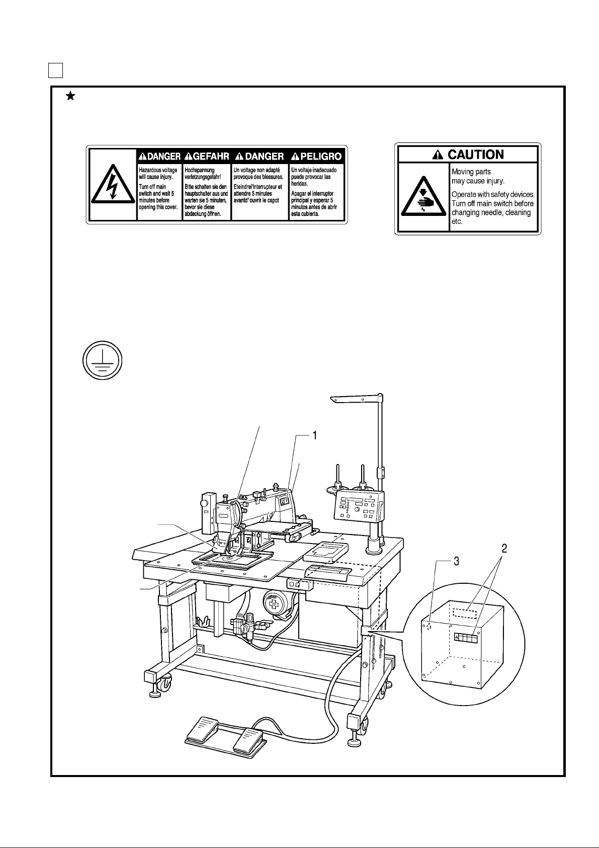
3 Warning labels
3
f
The following warning labels appear on the sewing machine.
Please follow the instructions on the lab els at all times when using the m achine. If the labels have been
removed or are difficult to read, please contact your nearest Brother dealer.
1
Be sure to connect the ground. If the ground connection is not secure, you run a high risk o
receiving a serious electric shock, and problems with correct operation may also occur.
Thread take-up cover
2
Safety devi ces
Eye guard
Finger guard
Thread take-up cover
Belt cover , etc.
Eye guard
Finger guard
Belt cover
1971S
BAS-341F, 342F
iv
Page 6

CONTENTS
1. NAME OF MAJOR PARTS
2. SPECIFICATIONS
3. PREPARATION
3-1. Before se ttin g up
3-2. Positioning
3-3. Tilting the sewing machine head
3-4. Connecting the ground wire
3-5. V-belt tension
3-6. Installing the foot switch
3-7. Installing the spool stand
3-8. Installing the programmer (option)
3-9. Adjusting the air pressure
..............................................................................................................................................................3
.........................................................................................................................................................................4
.....................................................................................................................................................................5
4. LUBRICATION
4-1. Lubrication points
.............................................................................................................................................................8
5. CORRECT USE
...........................................................................................................................................2
..................................................................................................................................................3
..................................................................................................................................4
...........................................................................................................................................5
...............................................................................................................................................5
................................................................................................................................................6
...............................................................................................................................................7
......................................................................................................................................................8
...................................................................................................................................................9
.................................................................................................................... 1
...............................................................................................................................6
5-1. Selecting the needle and thread ...................................................................................................................
5-2. Installing the needle and urnnin g the sew ing mac hine..................................................................................
5-3. Threading the upper thre ad ........................................................................................................................
5-4. Windin g th e l ow e r th rea d ............................................................................................................................
5-5. Replacing the bobbin case and th readi ng the thread .................................................................................
5-6. Sewing conditions and thread tensi on ........................................................................................................
5-6-1. Sewing conditions .................................................................................................................................................... 12
5-6-2. Lower thread tension ...............................................................................................................................................13
5-6-3. Upper thread tension ...............................................................................................................................................13
5-6-4. Thread take-up spring height ...................................................................................................................................13
5-6-5. Thread take-up spring tension.................................................................................................................................. 13
5-6-6. Pretension tension .................................................................................................................................................... 14
9
9
10
11
12
12
6. USING THE OPERATION PANEL
6-1. Explanation of panel .................................................................................................................................................... 15
6-2. Using the floppy disk ................................................................................................................................................... 17
6-3. Using the program R/W (Read/Write) switch .............................................................................................................19
6-4. Using the TEST switch (Checking the sewing pattern) ............................................................................................. 20
6-5. Using the emergency stop switch ............................................................................................................................... 21
6-6. Adjusting the sewing SPEED control ....................................................................................................................... 22
6-7. Changing the X-SCALE and Y-SCALE settings ........................................................................................................22
6-8. Using the bobbin thread counter ................................................................................................................................ 23
6-9. Using production counter ............................................................................................................................................ 24
6-10. Using single split mode .............................................................................................................................................25
6-1 1. Shifting a stitch pattern ..............................................................................................................................................26
BAS-341F, 342F
................................................................................................15
Page 7

7. SEWING
7-1. Before starting sewing....
7-2. Sewing operation
....................................................................................................................................................................27
............................................................................................................................................................27
................................................................................................................................................27
8. MAINTENANCE AND INSPECTION
8-1. Cleaning the shuttle hook
8-2. Lubrication
8-3. Draining the oil
8-4. Cleaning the control box air inlet port
8-5. Cleaning the eye guard
8-6. Checking the needle
........................................................................................................................................................................29
................................................................................................................................................................30
9. STANDARD ADJUSTMENTS
9-1. Adjusting the needle bar height
9-2. Adjusting the needle bar lift amount
9-3. Adjusting the needle clearance
9-4. Adjusting the driver needle guard
9-5. Adjusting the shuttle race thread guide
9-6. Adjusting the movable knife
9-7. Adjusting the presser foot
9-8. Chan gin g th e p resse r foo t l i ft
9-9. Adjusting the wiper
9-10. Adjusting the needle up stop position
9-1 1. Checking th e input senso r and DIP switch inpu t
9-12. Checking the input voltage
9-13. Clearing all memory settings
..........................................................................................................................................................38
.............................................................................................................................................29
.........................................................................................................................30
.................................................................................................................................................31
......................................................................................................................................................31
..........................................................................................................32
....................................................................................................................................32
...........................................................................................................................32
...................................................................................................................................33
...............................................................................................................................33
.....................................................................................................................33
.........................................................................................................................................34
..............................................................................................................................................36
.......................................................................................................................................37
......................................................................................................................38
...................................................................................................39
.........................................................................................................................................40
.....................................................................................................................................40
........................................................................................29
10. DIP SWITCH
10-1. Panel DIP switch functions
10-2. DIP switches inside the control box
.....................................................................................................................................................41
........................................................................................................................................41
.........................................................................................................................43
1 1. CHA NGING SPECIAL FUNCTIONS A ND
USING THE MEMORY SWITCHES
12. ERROR CODES
...........................................................................................................................................50
........................................................................................45
13. GAUGE PARTS LIST ACCORDING TO SUBCLASSES
14. NOTES ON THE PROCESSING AND PRODUCTION
OF PLATE BLANKS
15. TROUBLESHOOTING
16. OPTIONS
..............................................................................................................................................................58
.................................................................................................................................53
..........................................................................................................................54
...............................52
BAS-341F, 342F
Page 8

1. NAME OF EACH PARTS
1. NAME OF EACH PARTS
BAS-341F
■
Emergency stop switch
Thread wiper switch
Cotton stand
Operation panel
Programmer
BAS-342F
■
Solenoid valve
Integrater
Presser lifter pedal
Power switch
Control box
Starting pedal
1917S
Presser foot
Work cl a mp
Feed plate
1918S
1
BAS-341F, 342F
Page 9

2. SPECIFICATIONS
Stitch formation Single needle lock stitch
Sewing machine Lock stitch, pattern tacking sewing machine (with large shuttle hook)
Maximum pattern size BAS-341F: 250X 150 mm, BAS-342F: 300 X 200 mm
Maximum stitch number 20,000 (one pattern)
Stitch length 0.1 - 12.7 mm
Maximum sewing speed 2,500 rpm (When stitch length is 3 mm or less)
Feed mechanism Intermittent feed, pulse motor drive
Shuttle hook Double hook (Standard hook is sold separately)
Needle DP X 5, DP X 17, MR
Data storage method 3.5 floppy disk 2HD/1.44MB, 2DD
T e st function Operation test function provided for use with low speed drive
2. SPECIFICATIONS
Safety devi ce s
Work clamp height Max.30 mm
Work clamp Unit work clamp (special order-separate work clamp)
Work clamp lift stroke 18 mm
Intermittent stroke 0 or 3 (Factory default) - 8 mm
Weights
Power supply Single-phase 110V, 220V, 240V, 3-phase 220V, 380V, 400V, 900VA
Motor Three-phase 400 W induction motor
Air pressure 0.50 MPa 1.8 l/ min
Power table Use sitting or standing
Machine dimensions
Automatic stop function for activation in the event of misoperation realized with intermediate
stop function and safety circuits
Machine head: 80kg,
Control box: 10 - 20 kg (depending on destination)
BAS-341F 1,200W X 1,220D X 860H mm (Sitting)-1,130H mm (Standing)
BAS-342F 1,200W X 1,270D X 860H mm (Sitting)-1,130H mm (Standing)
BAS-341F, 342F
2
Page 10
3. PREPARATION
3. PREPARATION
Machine installation s hould onl y be carried out by
a qualified technician.
Contact your Brother dealer or a qualified
electrician for any electrical work that may need to
be done.
The sewing machine head weighs more than 200
kg. The installat ion should be carried ou t by two or
more people.
Do not connect the power cord until ins tallation is
complete, otherwise the m achine may operate if
the foot switch is depressed by mistake, which
could result in injury .
Be sure to connect the ground. If the ground
connection is not secure, you run the risk of
receiving a serious electric shock.
Hold the machine he ad with both hands b y t wo or
more peple when tilting it back or returning it t o its
original position. Furth er more, after tilting back the
machine head, do not push the fac e plate side or
the pulley side from above, as this could cause the
machine head to topple over, which may result in
personal injury or damage to the machine.
CAUTION
Install the belt cover an d the frame side cover to
the machine head and motor.
If using a work table which has casters, the
casters should be secured in such a way so that
they cannot move.
Be sure to wear protective goggles and gloves
when handling the lubricating oil and grease, so
that they do not get into your eyes or onto your
skin, otherwise inflammation can result.
Furthermore, do not drink the oi l or ea t the greas e
under any circumstances, as they can cause
vomiting and diarrhoea.
keep the oil out of the reach of children.
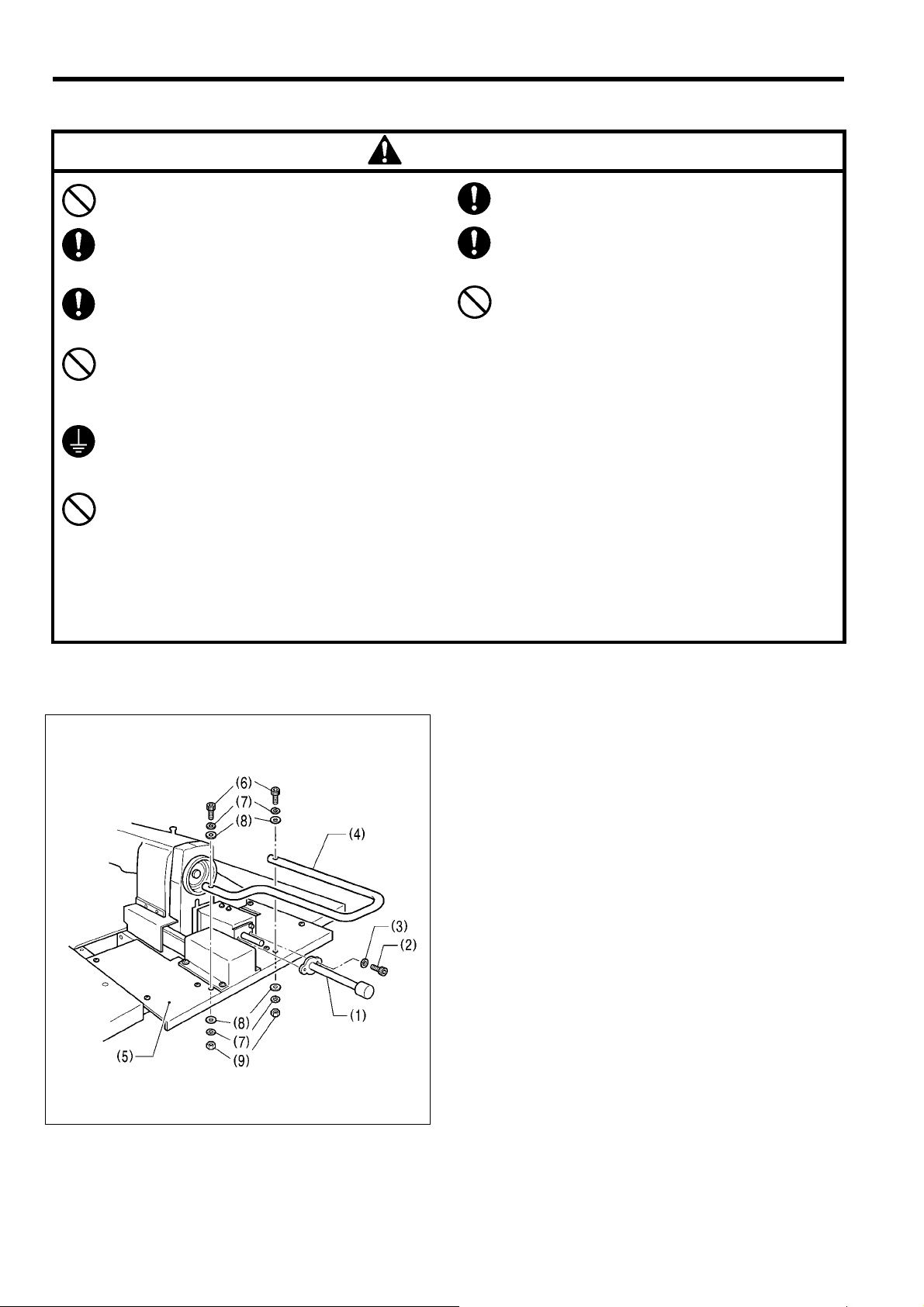
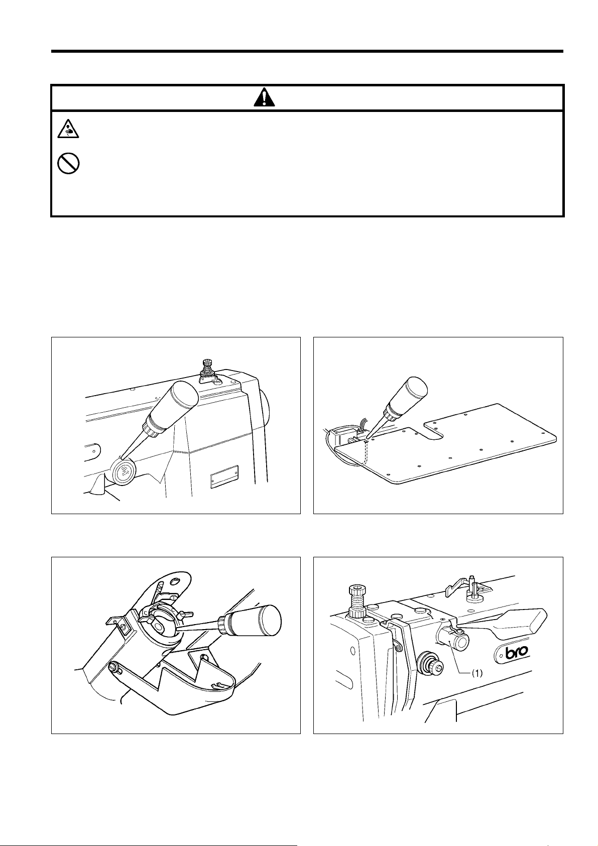
3-1. Before setting up
1. Ins tall the Y driving shaft guard (1) to the rear of the
arm with the bolt (2) and the spring washer (3).
2. Install the g uard ( 4) to the table rear c over (5) with the
bolt (6), spring washer (7), flat washer (8) and nut (9).
1919S
3
BAS-341F, 342F
Page 11
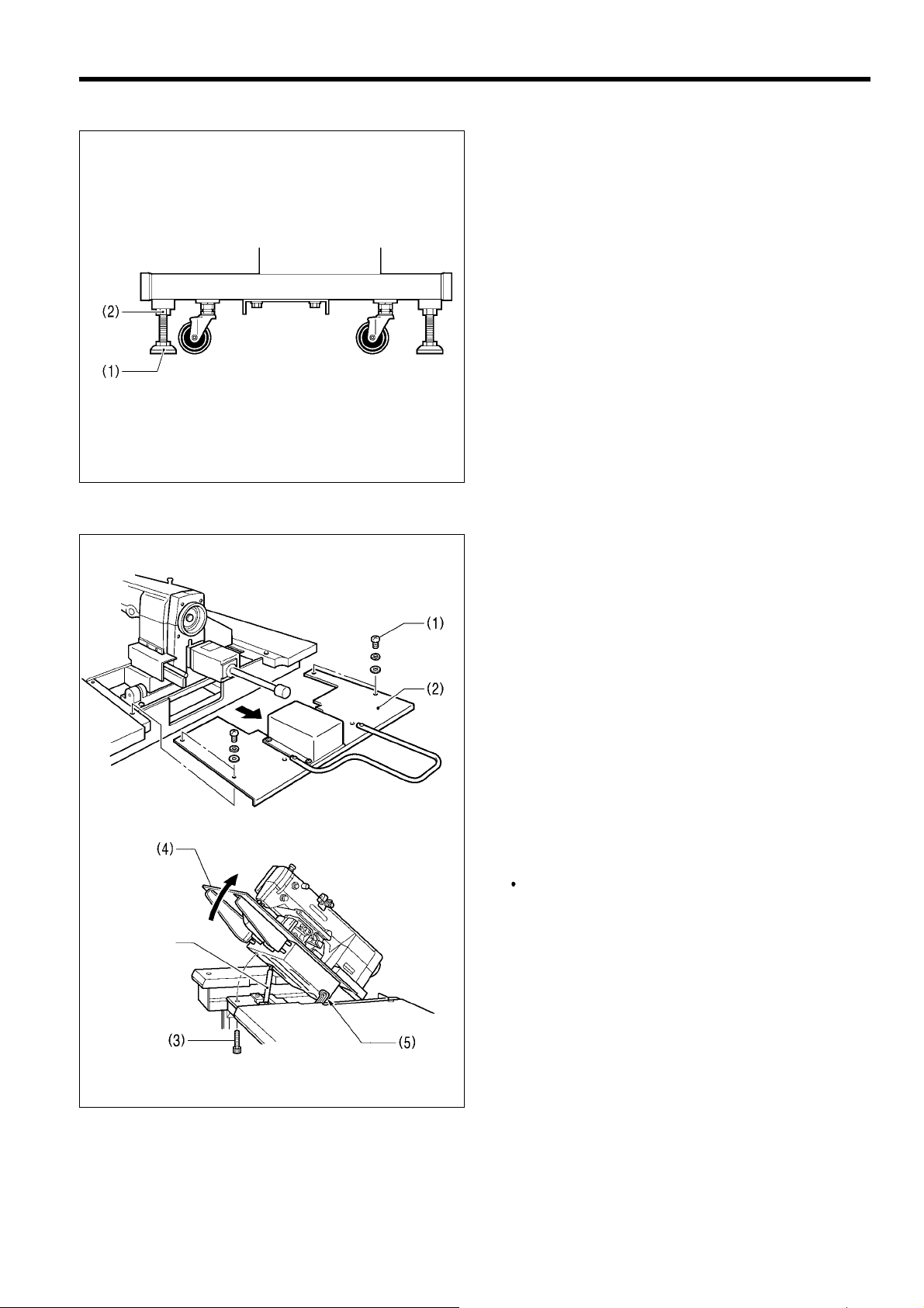
3-2. Positioning
3. PREPARATION
Decide the position for the sewin g machine. Loos en nuts
of four level adjusters (1) . Lower the level adjusters and
secure them with nuts (2).
Turning the level adjuster counterclockwise will raise its
height and turning it clockwise will lower it.
1920S
3-3. Tilting the sewing machine head
1921S
Gas spring
1. Remove screws (1) at the back of the work table, and
2. Remove bolt (3).
remove table cover (rear) (2).
The bolts are used to fix the machine in shipping.
Generally they are needless after removing them
keep them in another place.
3. Stand at the front of the table and slowly raise the
machine (4). Then lock it.
4. When returning the machine to its former position,
release lock (5). The gas spring will guide the machine
1922S
BAS-341F, 342F
to its original position.
4
Page 12

3. PREPARATION
3-4. Connecting the ground wire
CAUTION
Be sure to connect the ground. If the gr ound connection is no t secure, you run the risk of receiving a serious
electric shock.
Connection method for 3-phase power supply.
Red
White
Black
Yellow/Greeen
3-5. V-belt tension
3-phase
power supply
Yellow/Green
Connect to
ground
0064Q
These should approximately 10 - 12 mm of slack when Vbelt is loaded at 9.8 N . To adjust, loosen the two nuts (1),
and shift the motor up or down.
1923S
3-6. Installing the foot switch
Insert the connector of the foot switch (2) into the
connector (3) of the control box (1).
1924S
5
BAS-341F, 342F
Page 13
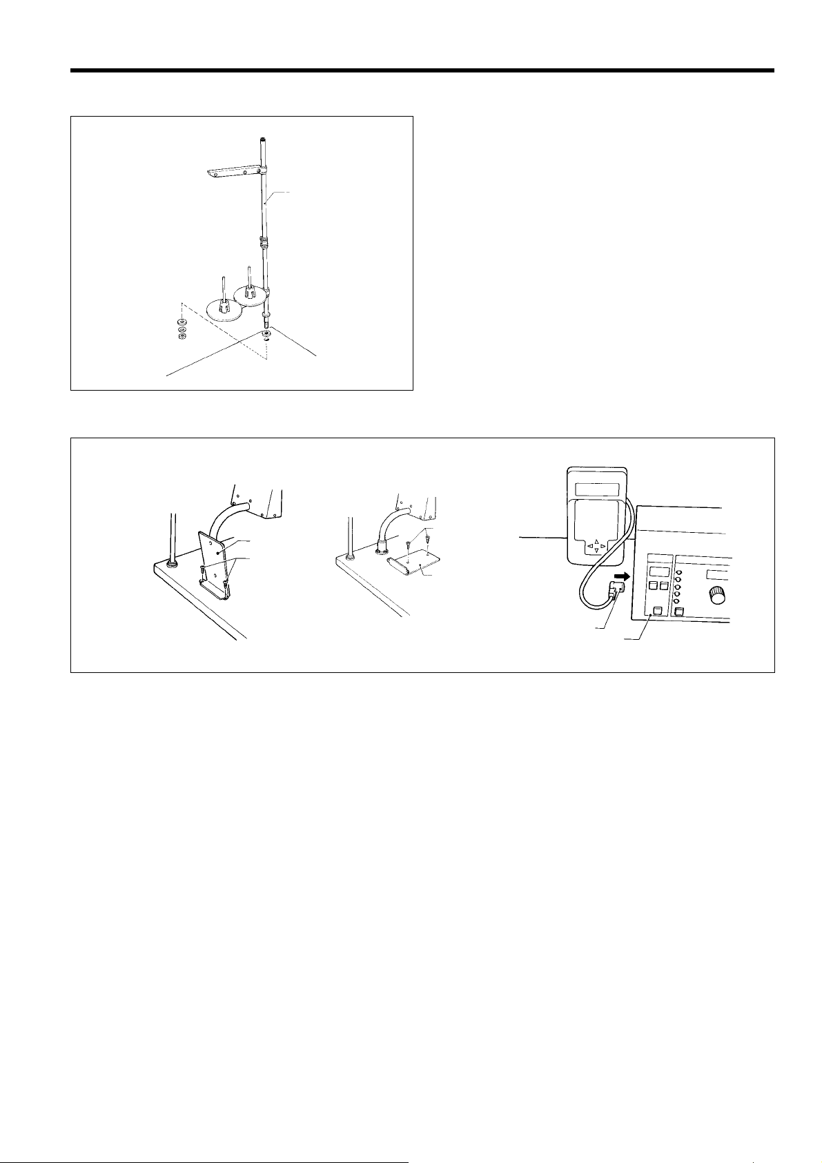
3-7. Installing the spool stand
(2)
(1)
Install the spool stand (1) to the table.
(1)
0073Q
3-8. Installing the programmer (option)
3. PREPARATION
[Vertical]
1181S
1. Install the programmer support (2) to the work table with the two screws (1).
2. Insert the programmer connector (4) securely into the left side of the operation panel (3).
[Flat]
(1)
(1)
(2)
(2)
(4)
1182S 1183S
(3)
BAS-341F, 342F
6
Page 14
3. PREPARATION
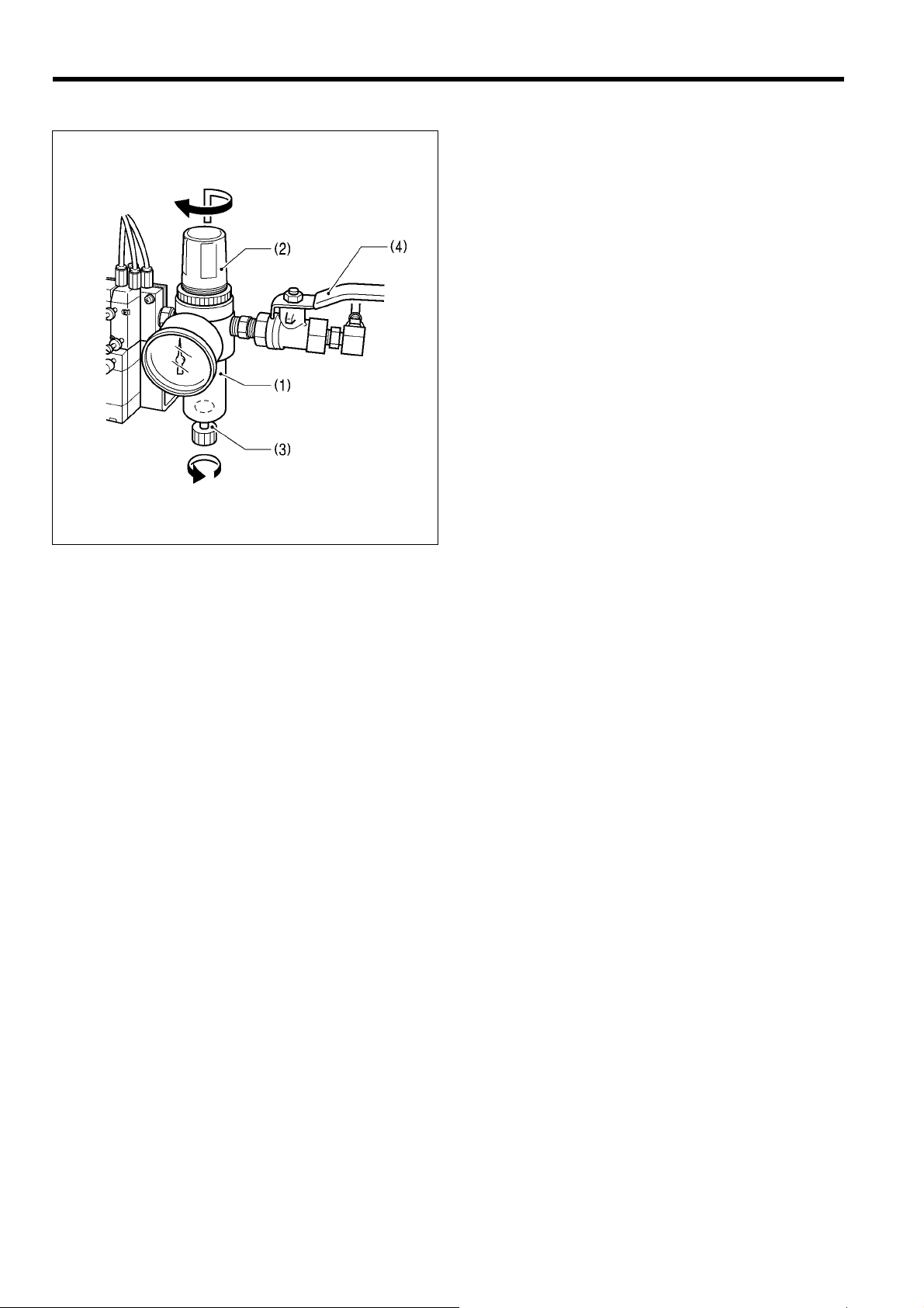
3-9. Adjusting the air pressure
1. Air pressure should be 0.5 MPa.
The air pressure can be adjusted by pulling up an d
turning the control knob (2) on the integrator (1).
After adjustment is complete, push the control knob
(2) downward to lock it.
2. If water stands in the bottle of the integrator (1) , turn
the drain cock (3) in the direction indicated by an arrow
to drain the water.
Note
Open the air cock (4) slowly .
1925S
7
BAS-341F, 342F
Page 15
4. LUBRICATION
CAUTION
Turn off the power switch before st arting lubricating, otherwis e the machine m ay operate if the foot switc h is
depressed by mistake, which could result in injury .
Be sure to wear protective goggles and gloves when handling the lubricating oil and grease, so that they do not
get into your eyes or onto your skin, otherwise inflammation can result.
Furthermore, do not drink the oi l or eat the greas e under any circ umstances, as they can cause vom iting and
diarrhoea.
Keep the oil out of the reach of children.
Note
• Fill the machine with oil when the oil level is down to about one-third full in the oil sight glass.
If oil is not added and the oil drops belo w this level, there is the danger that the machine may sei ze during
operation.
• Be sure to let the machine operate for a while after adding the oil.
• Use only specified Brother oil (Nisseki Mitsubishi Sewing Lube 10N; VG10) for the machine oil.
4-1. Lubrication points
4. LUBRICATION
1. Fill the arm-side oil tank with oil.
(Fill the oil tank with sewing machine oil.)
3. Add a drop of oil to the shuttle hook race.
1926S
1928S
1927S
2. Fill the bed-side oil tank with oil.
1929S
4. If using the liquid cool ing tank (1), fill it with sil icon oil
(100 mm
2
/S).
BAS-341F, 342F
8
Page 16
5. CORRECT USE
5. CORRECT USE
5-1. Selecting the needle and thread
Needle Thread Main application
DP X 5 #9 #100 - #60 Knitted wear
DP X 5 #16 #80 - #50 General clothing
DP X 17NY #19 #50 - #20 Denim
DP X 17 #21 #50 - #20 Denim
DP X 17 #25 #50 - #20 Leather•seat belts
5-2. Installing the needle and running the sewing machine
Turn off the power switch before installin g the nee dle, otherwis e the m achine m a y operate of the f oot s witch is
depressed by mistake and serious injury could result.
Different needles and threads are used for different sewing
applications.
Refer to the table at left for details on which needle.
CAUTION
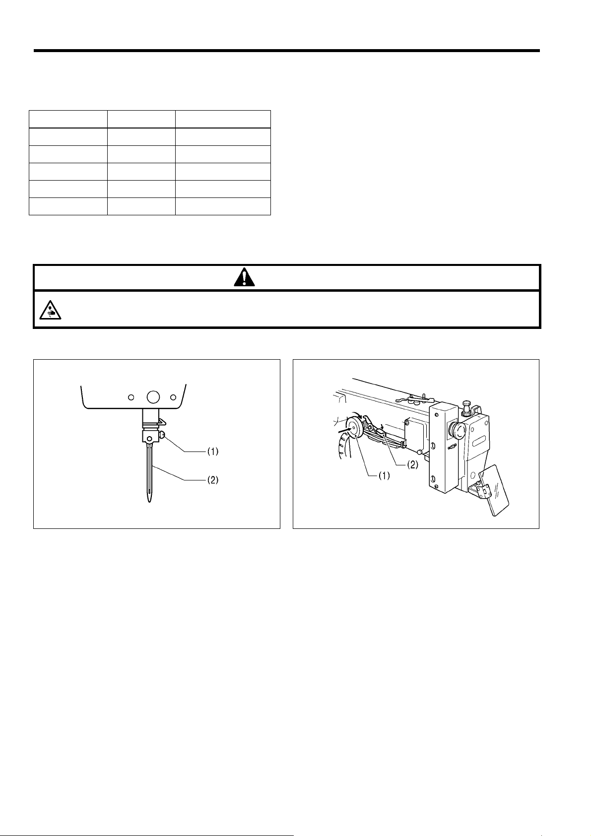
Installing the needle
■
Loosen the set screw (1), insert the needle (2) as far as
it will go so that the groove is facing toward you and
then tighten the set screw (1).
1930S
To turn the pulley by hand
■
Turning
Press
Simply press in on the pulley (1) to tur n it by hand. To
turn the pulley, press lever (2) down.
• After turning the pulley b y han d, be sure t o pr ess the
lever down to return the pulley to the normal
operating position.
Down
1931S
9
BAS-341F, 342F
Page 17
5-3. Threading the upper thread
CAUTION
Turn off the power switch before threadi ng th e thr ea d, ot herwise the machine m ay operate of the foot switch is
depressed by mistake and serious injury could result.
5. CORRECT USE
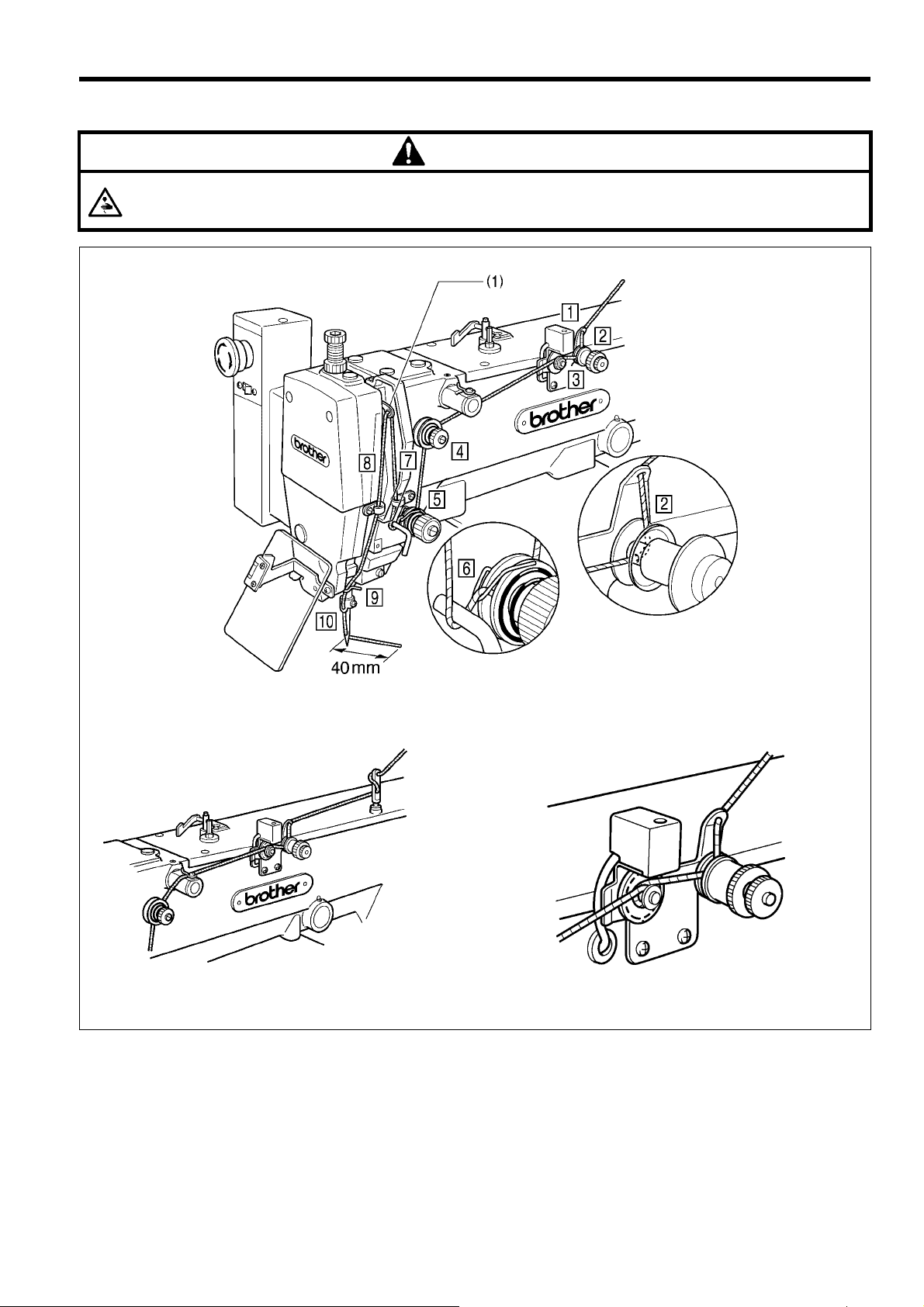
[When using cotton thread and spun yarn]
1932S
[With synthetic thread] [Threading in the upper thread breakage detector]
Real the thread from above once or
twice as the above figure.
1933S
■ Thread the upper thread correctly as shown in the illustration above.
Note
• Turn the machine pulley and raise the thread take-up lever (1) before threading the upper thread.
(This will make threading easier and it will prevent the thread from coming out at the sewing start.)
• When threading the thread through the needle, allow a distance of approximately 40 mm between the needle hole
and the end of the thread. If the trailing length of the thread is too long, it may cause the thread to.
1934S
BAS-341F, 342F
10
Page 18
5. CORRECT USE
5-4. Winding the lower thread
Do not touch or place anything against any of the moving parts while winding the lower thread, otherwise
personal injury or damage to the machine may result.
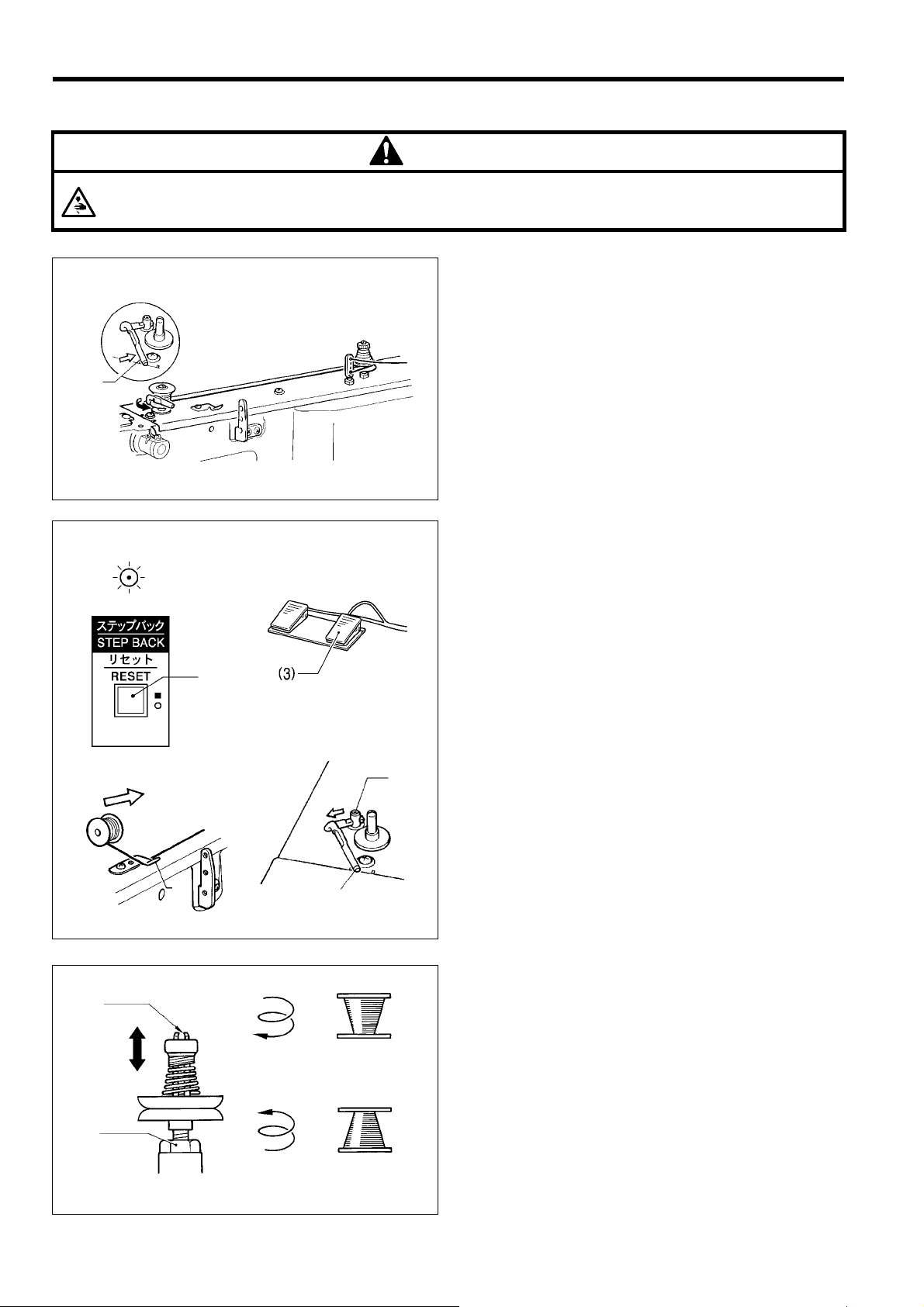
(1)
CAUTION
1. Place the bobbin all the way onto the shaft.
2. Thread the thread as shown in the illustrat ion at left,
wind the thread around the bobbin several times in the
direction of the arrow, and then press the bobbin
presser (1).
3. Turn on the power switch.
(The POWER indicator on the operation panel will
illuminate.)
1198S
1199S
0106Q
(2)
(1)
(4)
(2)
(1)
1935S
4. Check that the needle is not touching the presser foot,
and then while pressing the ST EP BACK switch (2),
depress the foot switch (3) to start the m achine. Ke ep
depressing the foot switch (3) until the lower thread
stops being wound onto the bobbin.
Release the STEP BACK switch (2) after the machine
starts operating.
If you release the foot s witch before winding is com pleted, depress it once m ore while pr essing a nd holding the STEP BACK switch (2).
5. The bobbin presser (1) will autom atically return to its
(5)
original position after a set amount of thread (80 - 90%
of the bobbin capacity) has been wound on.
6. Release the foot switch (3).
7. Remove the bobbin, hook the thread onto the knife (4),
and then pull the bobbin in the direction of the arrow to
cut the thread.
8. To wind more thread onto the bobbin, l oosen the set
0107Q
screw (5) and pull the bobbin presser (1) outward.
<< If the thread winds onto the bobbin unevenly >>
If the thread winds onto th e bobbin unevenly, loosen
the nut (1) and turn the bob bin winder thread tensi on
stud (2) to adjust.
A
Note
If the thread winds on as shown in A, turn the b obbin
winder thread tension stud (2) clockwise; if it winds on
as shown in B, turn the bobbin winder thread tension
stud (2) counterclockwise.
11
B
0108Q
BAS-341F, 342F
Page 19
5-5. Replacing the bobbin case and threading the thread
CAUTION
If the power switch needs to be lef t on whe n car rying out replacing the bobbin, b e extr emely careful to observe
all safety precautions.
The machine may operate if the foot switch is depressed by mistake, which could result in injury.
(ex. Continuing sewing from a stopping point)
(2)
(3)
(4)
5. CORRECT USE
30 mm
1936S
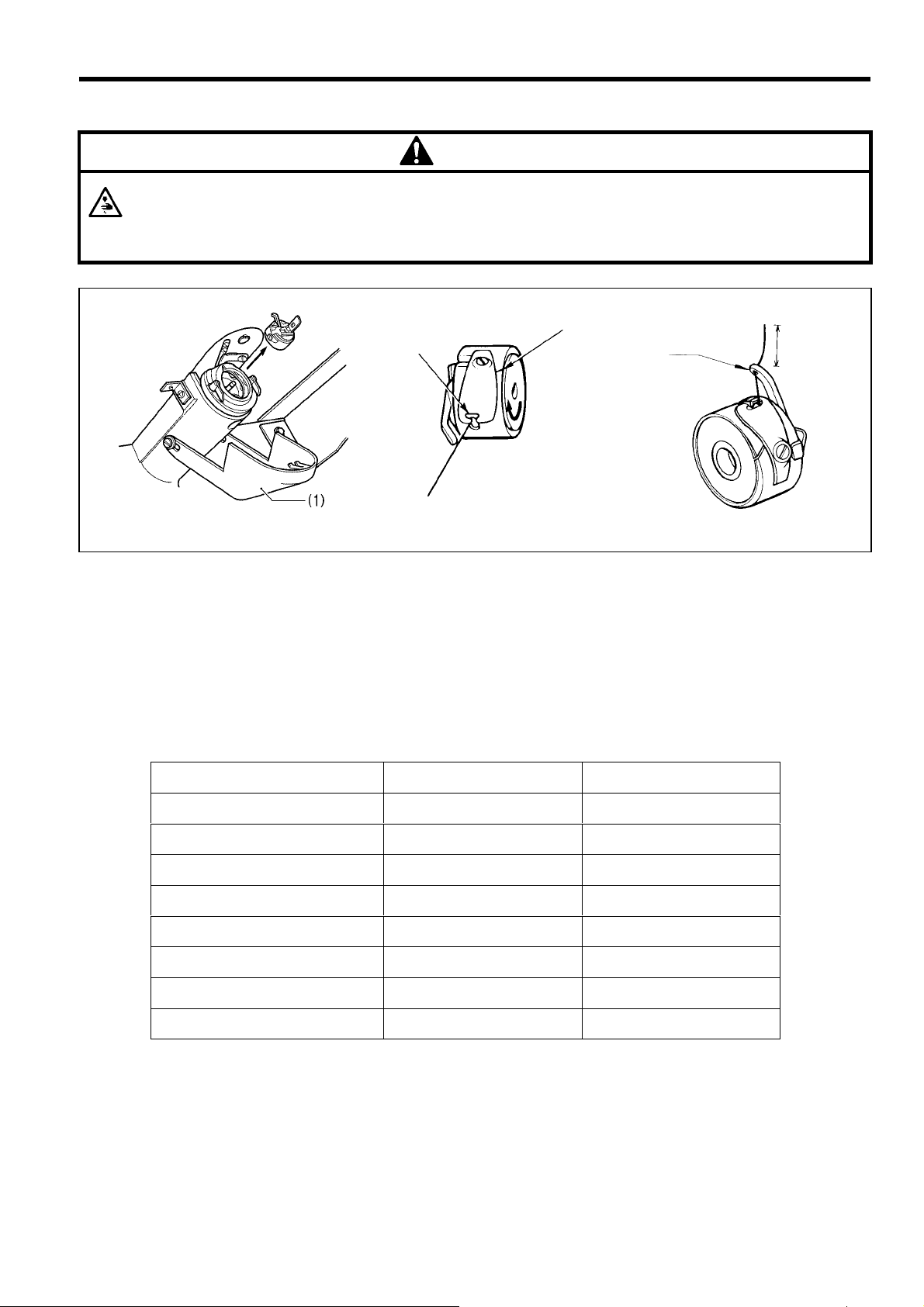
1. Pull the shuttle race cover (1) forward and then open the cover.
2. Lift the bobbin case latch and remove the bobbin case.
3. Insert a new bobbin into the bobbin case, and then pass the thread through the slot (2) and pull it out from the thread
hole (3). Check that the bobbin turns in the direction of the arrow when the thread is pulled at this time.
4. Pass the thread through the lever thread hole (4), and then pull out approximately 30 mm of thread.
0110Q
1202S
5-6. Sewing conditions and thread tension
5-6-1. Sewing conditions
Specifications For heavy materials
Upper thread # 20 or equivalent # 50 or equivalent
Lower thread # 20 or equivalent # 60 or equivalent
Upper thread tension (N) 1.5 - 2.0 0.5 - 1.0
Lower thread tension (N) 0.2 - 0.4 0.2 - 0.4
Thread take-up spring height 8 - 10 mm 6 - 8 mm
Thread take-up spring tension(N) 1.5 - 2.0 0.4 - 0.6
For medium materials
Needle DP X 17 # 21 DP X 5 # 16
Normal sewing speed 2000 rpm 2000 rpm
The sewing conditions given in the above table may need to be changed depending on the article being sewn.
BAS-341F, 342F
12
Page 20
5. CORRECT USE
(5)
5-6-2. Lower thread tension 5-6-3. Upper thread tension
Weaker
Stronger
(1)
0112S
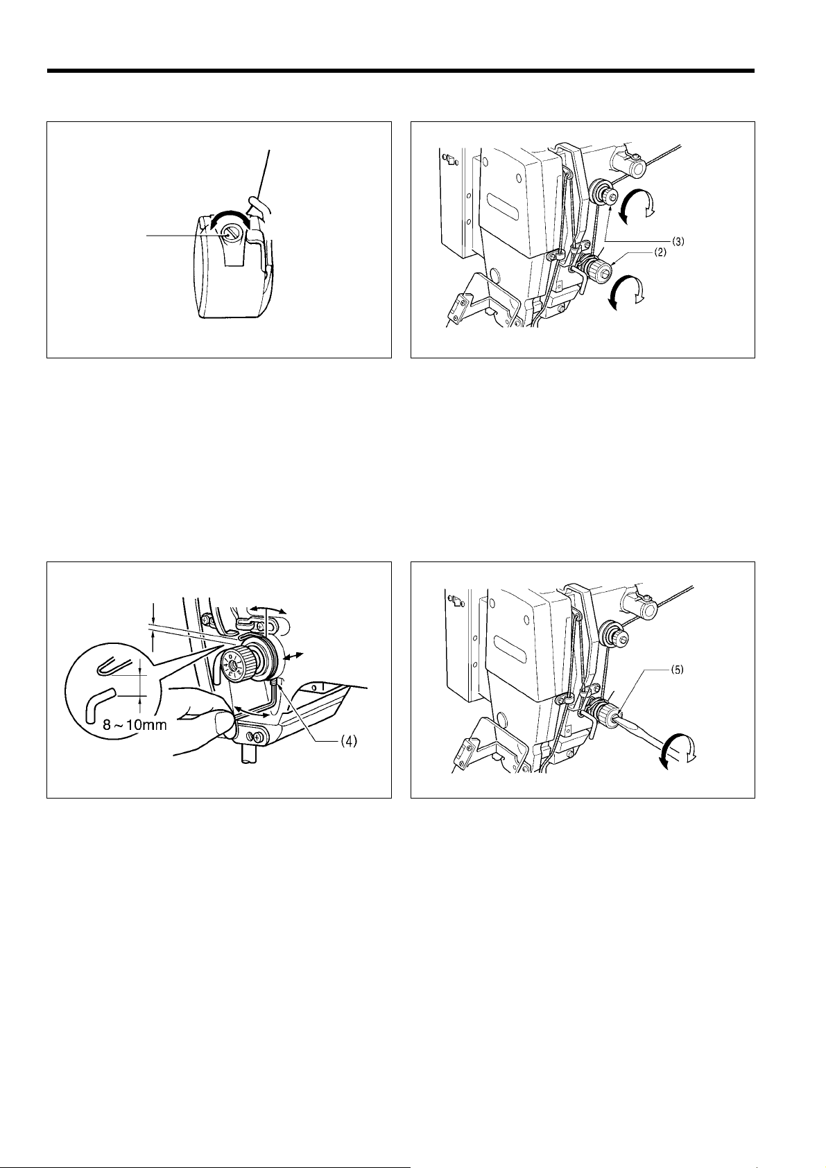
Set the lower thread tension to as weak a tension as
possible and so that the bobbin case drops by its own
weight when the end of the thread is held. Turn the
adjusting screw (1) to adjust the tension.
Weaker
Turn the tension nut (2) (main tension) to adjust the tension
as appropriate for the material being sewn.
Furthermore, turn the thread n ut (3) ( sub-tensio n) to adjust
the remaining length of upper thread to 35 - 40 mm.
Stronger
Weaker
Stronger
1937S
Note
If the lower thread tens ion is too weak, it m ay not be
possible to cut the lower thread properly during thread
trimming .
5-6-4. Thread take-up spring height 5-6-5. Thread take-up spring tension
Lower
Higher
1938S
Loosen screw (4) and turn the entire thread take-up unit to
adjust so that the height of the thread take-up spring is 8 10 mm
BAS-341F, 342F
13
Stronger
Weaker
1939S
Adjust the thread take-up spring tension by turning the
tension stud
with a screwdriver.
Page 21
5-6-6. Pretension tension
5. CORRECT USE
1940S
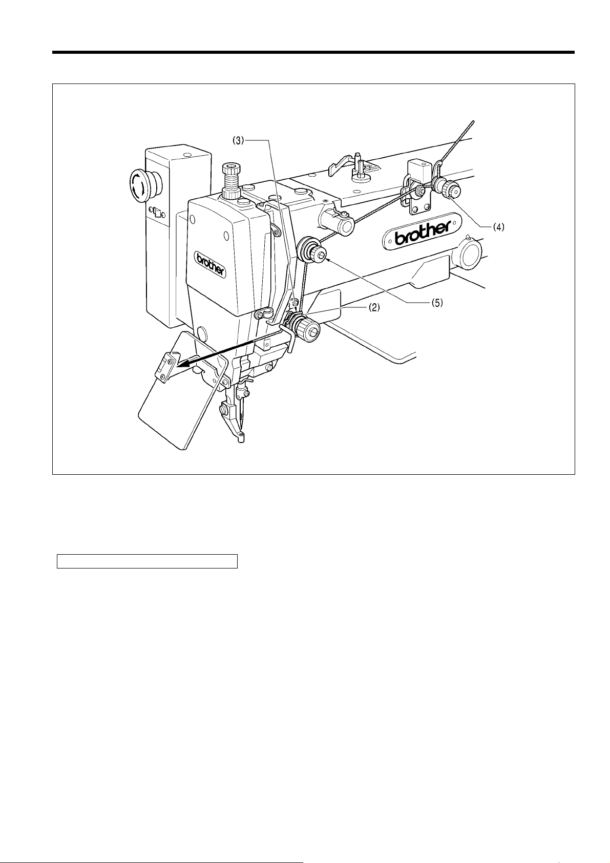
1. Raise the work clamp (1) and open the main tension disc (2).
The thread take-up spring (3) should not operate when the thread is pulled in the direction of the arrow.
2. Set the thread tension for the thread breakage detector pretension (4) to approx. 5 g.
Weaken the thread tension for the machine head pretension (5) as much as possible.
Standard for balance of thread tension
Adjust the thread tensions so that the total tension for the pretensions (4) and (5) is lower than the tension for the thread
take -up spring.
When the thread breakage detector is activated, set to ON DIP switch A – 8.
(Detection precision : DIP switch B – 5, Refer to “ DIP SWTCH “.)
Note
If misoperation of the thread breakage detector continues, repeat the adjustment procedure above.
(Such misoperation is most likely to occur when synthetic fiber yarns are used.)
BAS-341F, 342F
14
Page 22

6. USING THE OPERATION PANEL
(7)
(8)
(9)
(10)
(11)
6. USING THE OPERATION PANEL
6-1. Explanation of panel
(5)
(2)
(3)
(4)
(6)
(1) POWER indicator........................When the power is turned on, the indicator lights to show that the power is on.
(2) PROGRAM No. display..............Displays the program number 00 - 99.
(3) Program select switch.................Used to select the program number when reading a program from or writing a
program to disk.
(4) Program Read/Write switch ....... Used to read a program from floppy disk, or to write a newly programmed stitch
pattern to floppy disk.
Up to ten patterns (00 - 99) can be stored on each disk.
(5) Display screen.............................Used to display data such as menus, errors and memory switch settings.
(6) Menu s witch.................................Used to select the desired menu (scale, speed, bobbin thread counter, split No.).
One of the indicators (7) - (11) illuminates to indicate the menu selected, and the
setting for that menu them appears on the display screen (5).
The illuminated indicator changes in the following order each time the switch is
pressed.
(1)
1207S
X-SCALE indicator (7) Y-SCALE indicator (8) SPEED indicator (9)
B.T . COUN TER indicator (10) SPLIT NO. indicator (1 1)
(7) X-SCALE indicator .....................Illuminates when X-scale mode has been selected using the menu switch (6).
(8) Y-SCALE indicator......................Illuminates when Y-scale mode has been selected using the menu switch (6).
(9) SPEED indicator .........................Illuminates when speed mode has been selected using the menu switch (6).
BAS-341F,342F
15
Page 23

(10)
(1 1)
(5)
(5)
6. USING THE OPERATION PANEL
(13)
(14)
(12)
(16)(6)
(15)
(17)
1208S
(10) Bobbin Thread COUNTER............Illuminates when bobbin thread counter mode has been selected using the menu
indicator switch (6).
(11) SPLIT NO. indicator........................Illuminates when split No. mode has been selected using the menu switch (6).
(12) Dial .................................................The setting shown on the displa y screen (5) can be changed by turnin g this dia l
while pressing the STEP BACK switch (17).
(13) Bobbin Thread SET switch.................Used to store the number of work pieces displa yed in the bobbi n threa d count er
to floppy disk.
(14) Bobbin Thread CHANGE ..............Used to continue sewing after replacing the bobbin thread.
switch (An alarm will sound when the counter reads <000>. Sewing is not possible when
the counter reads <000>.) (Refer to "6-8. Using the bobbin thread counter".)
(15) TEST switch ...................................Used to move the feed mechanism only in or der to c onf ir m a programmed stitc h
pattern.
(16) TEST indicator................................Lights when the TEST switch is pressed.
(17) STEP BACK switch........................ Used when winding a fresh bobbin, or when correcting a stitch pattern due to a
(RESET switch) broken needle thread.
Also used to reset error displays.
BAS-341F, 342F
16
Page 24

6. USING THE OPERATION PANEL
6-2. Using the floppy disk
<Compatible types of floppy disk>
Data type
300E type
(300F type)
T a jima embroidery
data
Old 300A type
Old 300 data
• The above four types of data can all be read, but when writing t o disk, all data is autom atically converted to 300F,
300E data when writing to 2HD disks and 300A data when writing to 2DD disks.
• When using a 2HD disk, use a disk which has been pre-formatted as a 1.44 MB disk. (The programmer can be used
to format these disks. Refer to the programmer instruction manual for details.)
• TFD embroidery data can be em broidered after it has been converted b y the programmer to BAS-300F and BA S300E data.
• Restriction on using 2DD floppy disks.
In order to maintain compatibility with the old 300A series, the following restrictions have been placed on the use of
the new functions which have been added to the E series.
No. of stitches
programmed
20,000 stitches per
pattern 100 pattern
Up to a maxi-mum
of 360,000 stitches
50, 00 0 st it ch es per pa tte rn 0.1 mm/pulse
4,000 stitches per
pattern 10 patterns
Up to a maximum of
40,000 stitches
2,000 stitches per
pattern 10 patterns
Up to a maximum of
20,000 stitches
Data resolution Disk Format
0.05 mm/pulse Yes
0.1 mm/pulse Yes
0.2 mm/pulse
2HD 1.44 MB
2DD
Automatically
formatted
Write
enabled
No
No
Restricted function A series (2DD) F, E series (2HD)
Resolution 0.1 mm/pulse 0.05 mm/pulse
Low-speed conversion
Split function
during embroidering
Needl e do wn s top f or spli t Not available Available
Expansion option output Not available Available
2 types
(400 and 1,200 revolutions)
Not available Available
4 types (400, 600, 800and
1,200 revolutions)
Applicable
command
[668] L
[669] L
[220] L
[230] L
[221] L
[231] L
17
BAS-341F,342F
Page 25

Setting the floppy disk
(2)
(5)
(4)
6. USING THE OPERATION PANEL
Unlocked writing possible
Window open(3)
(1)
(6)
locked writing possible
1209S
1210S
1211S
1. Turn on the power switch (1). The POWER indicator (2) will illuminate and the machine m odel num ber will appear o n
the display screen.
2. Hold the disk (3) with the la bel up and th e shutter to the f ront, and insert the disk into the drive (4). It will click into
place.
3. T o eject the disk, press the eject button (5).
Note
• Slide the write protector (6) on the back of the disk up (the window opens) to lock the disk and prevent accidental
erasure of the disk contents.
• Inserting the disk into the drive upside down or backwards m ay damage the drive and will prevent reading or
writing of data.
• Be sure to store your disks away from any magnets or magnetic sources, including radios, televisions, telephones, and other devices. Magnetism can erase or damage disk contents. Also, be careful to prevent
exposure of the disk to oil or dust.
• Be sure to make a copy of the floppy disk containing sewing data and keep the master floppy disk.
• When the R / W operation is not in operation, eject the floppy disk from the floppy disk drive and keep it in a case
for floppy disk only to prevent exposure of the disk to dust.
When the “E.4F” error (Reading error of sewing data) occurs ver y often;
1. Clean the floppy disk drive using the cleaning disk.
2. Read the sewing data. If the “E.4F” error occurs again, the floppy disk may be damaged. In this case, clean the floppy
disk drive with the cleaning disk again.
3. Read the sewing data from the mas ter floppy disk and write it in a new flopp y disk. Do not use any dam aged flopp y
disks again.
How to use the cleaning disk
1. Insert the cleaning disk into the floppy disk drive.
2. Select a program number (0-9), and press the “R/W” switch. If you select the same program number for cleaning every
time, the same location of the clea ning d isk is used and the lifetim e of the cleaning dis k will become shor t. Next tim e
you clean it, select a different number.
3. After the cleaning is com pleted, the “E.4F” error appears . The error appears because the cle aning disk has no data.
This is normal.
4. Cancel the error and eject the cleaning disk.
BAS-341F, 342F
18
Page 26

6. USING THE OPERATION PANEL
6-3. Using the program R/W (Read/Write) switch
Programmed stitch patter ns stored on flopp y disk can be read into memory, and newl y programmed patterns can be
written to disk for permanent storage and later recall.
1212S
(7)
(1)
(5)
Insert the floppy disk (1 ) containing or whic h is to contain
the programmed stitch pattern.
To READ a pattern to memory
Press the program select switch (3) on the operation
panel. The program number will then appear in the
PROGRAM NO. displa y (2). After selecting the desired
program number, press the R/W switch (4). The disk drive
indicator (5) will illuminate and a "P" will appear on the
PROGRAM NO. display (2) to indicate that the data is
being read. When the alarm sounds and the disk drive
indicator (5) turns off, the program number will then flas h
in the PROGRAM NO. display ( 2) instead of the "P" to
indicate that the reading of the data is complete.
(2)
(3)
(4)
(7)
(8)
1213S
1215S1214S
To WRITE a patte rn to disk
Press the program select switch (3) on the operation
panel to select the desired program number. After
programming the pattern using the stitch programmer,
press the R/W switch (4) The disk drive ind icator (5) will
illuminate and a "P." will appear on the PROGRAM NO.
display (2) to indicate that the data is being written. When
the alarm sounds and the disk drive indicator (5) turns off,
the program number will then flash in the PROGRAM NO.
display (2) instead of the "P " to ind ic ate t hat th e writ ing of
the data is complete.
If an error message is displayed
If an error message code is displayed in the displa y (7),
and alarm will sound.
Press the emergenc y stop switch (6) on the front of the
machine to stop sewing machine operation, and then
refer to and follow the error code list on page 63.
Clearing the error
1. Turn the EMERGENCY STOP switch (6) clockwise
and then pull it forward to release it.
2. Press the STEP BACK (RESET) switch (8) on the
operation panel
(when memory switch No. 0d is ON).
If memory switch No. 0d is OFF, press the
EMERGENCY STOP switch (7) once more to release
it.
19
1941S
BAS-341F,342F
Page 27

6. USING THE OPERATION PANEL
(15)
6-4. Using the TEST switch (Checking the sewing pattern)
Use the TEST switch to begin sewing again from any desired point when the thread breaks or the bobbin thread runs out.
1217S
1215S
(16)
(17)
1. Press the TEST switch (15). The indicator (16) will
light.
2. If the work clamp is raised, depress the work clamp
lifter pedal (2) to lower the work clamp.
3. Press the starting pedal (1).
Note
After the feed mechanism has returned to the
home position, it will then m ove the sewing start
position and the program number will stop
flashing.
This only occurs the first time that a program is
selected.
4. Press the starting pedal ( 1). (The needle will remain
stationary as the work clamp advances through the
pattern at low speed one stitc h at a time. Press the
presser lifter pedal (2) to fast forward.
• If the STEP BACK switch (17) is pressed while moving
at low speed when memor y switch No. 20 is ON, the
work clamp will move in the forward direction in steps
of 100 stitches.
5. When the work clamp reaches the desired position,
press the TEST switch (15). The work clamp will stop,
and the test indicator (16) will go out. If the work clamp
was stopped too early, press theTEST switch (15)
again to proceed.
• If the work clamp was stopped too late, press the
STEP BACK switch (17) to advance the work clamp
one stitch at a time.
1942S
Resuming operation from a stopping poing
6. Sewing will start when the starting pedal (1) is
pressed.
BAS-341F, 342F
20
Page 28

6. USING THE OPERATION PANEL
6-5. Using the emergency stop switch
Press the emergenc y stop switch to im mediately stop the sewing machine during actual sewing or when in the tes t
mode.
1941S
Clearing the error
1. Turn the EMERGENCY STOP switch (6) clockwise
and then pull it forward to release it .
2. Press the STEP BACK (RESET) switch (17) on the
operation panel. (The buzzer will stop sounding.)
3. If you do not wish to resume sewing, press the
EMERGENCY STOP switch (6) once more to release
it, and then press the STEP BACK (RESET) switch
(17) so that the operation pan el dis play flas hes. The
sewing machine will then be ready for the next sewing
operation.
* If memory sewing No. 0d is OFF, press the EMER-
GENCY STOP switch (6) once more to release it.
1215S
1219S
1200S
(15)
(17)
(18)
(17)
1215S
Continuing sewing from a stopping point
If you press the EMERGENCY STOP switch after the
thread breaks or the bobbin thread runs out during sewing,
you can then resume swing from the point where the
thread broke or ran out.
1. Press the EMERGENCY STOP switch to release it.
2. Press the STEP BACK (RESET) switch (17) to trim
the thread.
3. Press the STEP BACK (RESET) switch (17) once
more.
(The sewing machine will move stitch by stitch in the
reverse direction while this switch is pressed.)
If the sewing machine m oves back too far, press the
TEST switch (15) to move it forward again. Press the
TEST switch (15) again to stop the machine.
4. After you have reached the desired pos ition, depress
the starting pedal to start sewing.
21
BAS-341F,342F
Page 29

6. USING THE OPERATION PANEL
6-6. Adjusting the sewing SPEED control
The sewing speed can be changed in steps of 100 rpm to the appropriate speeds for each stitch length setting.
1. Press the MENU switch ( 6) until t he SPEED indicator
(9) illuminates.
2. While pressing the STEP BAC K switch (17), turn the
dial (12) until the desired speed is displayed.
• The display will change in steps of 10 rpm.
(9)
(17)
(6)
(12)
1220S
1215S
6-7. Changing the X-SCALE and Y-SCALE settings
1. Press the MENU switch (6) until the X-SCALE
indicator (7) or the Y-SCALE indicator (8) illuminates.
2. While pressing the STEP BAC K switch (17), turn the
dial (12) until the desired ratio flashes on the display.
• The scale setting is displayed as a percentage.
1221S
(7)
(8)
(6)
(17)
(12)
1215S
3. The program number will flash, and after the home
position is detected the flashing will stop.
BAS-341F, 342F
22
Page 30

6. USING THE OPERATION PANEL
(10)
6-8. Using the bobbin thread counter
Set the bobbin thread counter to display the number of pieces of the selected pattern which can be sewn with the amount
of thread on the bobbin to avoid running out of bobbin thread in the middle of a patern.
(5)
(13)
(14)
(6)
1. Press the MENU switch (6) until the B.T . COUNTER indicator (10) illuminates.
• The bobbin thread counter can be s et to an y number fr om <001> to <999>. If the counter is set to < 000>, s ewing
continues irrespective of the amount of bobbin thread remaining.
2. While pressing the STEP BACK switch (17), turn the dial (12) to set the number of articles to be embroidered.
3. Insert the floppy disk and press the bobbin thread SET switch ( 13). An alarm will beep twice. Th is will record the
number of work pieces shown in the counter (5) to the disk.
4. The number shown in the counter (5) will decrease one each time the stitch pattern is completed. When the number of
patterns shown in the counter is s e wn, the counter (5) will red <000>, and an a larm will sound. (The sewing machine
will not start even if the start switch is pressed.)
5. Press the bobbin thread chan ge switch (14) and replace the bobbin. T he alarm will stop, and the number of work
pieces set in step 3 will be displayed again in the counter (5).
(12)
(17)
1222S
23
BAS-341F,342F
Page 31

6. USING THE OPERATION PANEL
(6)
(10)
(11)
6-9. Using production counter
Both PRO. NO. and B.T. COUNTER displays are available for the five-digit PRODUCTION counter.
(5)
(2)
(13)
(14)
(12)
1. While pressing the TEST switch (15), press the B.T. SET switch (13) The B.T . COUNTER indicator (10) and the SPLIT
NO. indicator (11) will both illuminate, and the production counter value will appear on the program number display (2)
and on the display screen (5).
• Press the B.T . CHANGE switch (14). The PRODUCTION counter will display <00000>.
• The production counter can be set to a value between <00000> and <99999> by turning the dial (12) while
pressing the STEP BACK switch (17).
2. Depress the start switch to start embroidering.
3. Press the TEST s witch (15) or the MENU switch (6). T he TEST indicator (16) will switch off and the contents of each
display screen will return to the normal display .
(16)
(15)
(17)
1223S
BAS-341F, 342F
24
Page 32

6. USING THE OPERATION PANEL
6-10.Using single split mode
By using single split mode, it is possible to change up to 100 patterns immediately.
(5)
(17)
(6)
1224S
1225S
(12)
1215S
1. Move DIP switch B No. 1 to the ON position. This will activate single split mode.
(Refer to "10.DIP SWITCH".)
2. Turn on the power read in the patterns which have been programmed for split sewing.
3. Press the MENU switch (6) unt il t he SPL IT NO. indicator (11) is illuminated. "1" will then ap pear i n the dis p la y scr een
(5). Then, while pres sing the STEP BACK s witch (17), turn the dial (12) to change the contents appeari ng on the
display screen (5) in order.
(Example) If three patterns have been program med for split s ewing, the number on the display scr een changes in
the following order: "1" “2" "3" "1" "2" ...
4. When the starting switch is pressed, only the pattern displayed on the display screen (5) will be sewn.
Note
As to split sewing, refer to the instruction manual of the “electronic programmable pattern tacker programmer”.
25
BAS-341F,342F
Page 33

6. USING THE OPERATION PANEL
6-1 1. Shifting a stitch pattern
• Programs which have already been programmed can be moved up, down and to the left and right.
(However, such patterns will be reset if the power supply is turned off or the program number is changed.)
• The feed position can be set to the any position desired.
(5)
(2)
(7)
(8)
(10)
(4)
(16)
1226S
(6)
(12)
(15)
1943S
1. After the program data has been r ead, depress the start switch to move the feed m echanism to the sewing start
position. If you carry out the followin g procedure while the program number display (2) is flas hing (if the s tart switch
has not been depressed) (The feed position can be s et to any position, but it will not be possibl e to move the
stitch pattern .
2. Press the MENU switch (6) until the B.T. COUNTER indicator (10) illuminates.
3. Press and hold the TEST switch (15) and press the R/W switch (4). The test indicator (16) will light, and < > will
appear in the counter (5).
4. Press the MENU switch (6) so that either the X-SCALE indicator (7) or Y-SCALE indicator (8) illuminates.
5. Turn the setting dial (12) to move the feed mechanism one pulse at a time.
• If the setting dial is turn ed counterclock wise while the X-SCAL E indicator is i lluminated, the feed m echanism will
move to the right.
• If the setting dial is turned clockwise while the X-SCALE indicator is illuminated, the feed mechanism will move to
the left.
• If the setting dial is turn ed counterclock wise while the Y-SCAL E indicator is i lluminated, the feed m echanism will
move up.
• If the setting dial is turned clockwise while the Y-SCALE ind icator is illum inated, the feed mechanism will move
down.
6. When the TEST switch (15) is pressed after the above fine adjustments have been made, the TEST indicator (16) and
display window (5) will both switch off and movement of the stitch pattern will be completed.
Note
When moving the stitch pattern, the sewing start position can be moved to any desired point within the sewing area,
but if the pattern goes outside the sewing area, an error will occur during sewing and you will not be able to sew the
pattern. Give consideration to the pattern as a whole when moving it.
BAS-341F, 342F
26
Page 34

7. SEWING
7. SEWING
Turn off the power switch at the following times, otherwise the machine may operate if the foot switch is
depressed by mistake, which could result in injury .
• When replacing the bobbin and needle
• When not using the machine and when leaving the machine unattended
Do not touch any of the moving parts or press any objects against the machine while sewing, as this may result
in personal injury or damage to be machine.
7-1. Before starting sewing....
CAUTION
• Check that the needle bar is at the highest position.
Turn the machine pulley so that the index mark (1) on
the pulley is almost aligned with the point where belt
cover U and belt cover D meet.
* If the machine is started while the index mark (1) is not
correctly aligned, error message "E-22" will be
displayed (only when memory switch No.14 is on).
7-2. Sewing operation
(6)
(3)
(4)
(5)
1944S
1. Turn the power switch on.
(The power indicator on the operation panel will light.)
2. Insert the floppy disk (3).
3. Press the PRO. No. selection switch (4) to select the
desired program number.
4. Press R/ W switch (5 ).
The floppy disk drive indicator will light and the
PROGRAM NO. display (6) will show a “P” while
the data is being read. When reading is completed,
an alarm will sound and th e indicator will go out,
then the PROGRAM NO. dis play (6) will blink the
program number.
1229S
27
1213S
BAS-341F,342F
Page 35

7. SEWING
Note
When the power is turned on after once being turned off, the same pattern of sewing can be continued since the
machine will stores the sewing data from the last time.
5. Step on the presser lifter switch (2) to raise the presser
foot.
6. Insert the work piece under the work clamp, and press
the presser lifter switch (2) to lower the cla mp.
7. Press the starting pedal (1).
Note
The work clamp will return t o the origin, and will
then advance to the sewing start position and
blinking will stop. This is only required the first
time a program is sewing.
8. Press the starting pedal (1) again to start sewing.
After sewing is completed, the thread cutter will
automatically operate, then the work clamp will rise.
1942S
BAS-341F, 342F
28
Page 36

8. MAINTENANCE AND INSPECTION
8. MAINTENANCE AND INSPECTION
CAUTION
Turn off the power switch before starting any cleani ng work, otherwise the machine ma y operate if the foot
switch is depressed by mistake, which could result in injury.
Be sure to wear protective goggles and gloves when handling the lubricating oil and grease, so that they do not
get into your eyes or onto your skin, otherwise inflammation can result.
Furthermore, do not drink the oi l or eat the greas e under any circ umstances, as they can cause vom iting and
diarrhoea. Keep the oil out of the reach of children.
8-1. Cleaning the shuttle hook
(5)
1936S
1. Pull the shuttle hook cover (1)
forward to open, and t hen remove
the bobbin case.
2. Open the large shuttle hook set
claw (2) in the direction indicated
by the arrow, and then remove the
large shuttle hook (3) and the inner
shuttle hook (4).
1945S
3. Clean all the dust and thread ends
from around the driver (5), the to p
of the shuttle hook thread guide
and the shuttle race.
8-2. Lubrication
Note
• Fill the machine with oil when the oil level is down to about one-third full in the oil sight glass.
• If oil is not added and the oil drops below this level, there is the danger that the machine may seize during
operation.
• Be sure to let the machine operate for a while after adding the oil.
• Use only specified Brother oil (Nisseki Mitsubishi Sewing Lube 10N; VG10) for the machine oil.
1946S
1926S
1. Fill the arm-side oil tank with oil. 2. Fill the bed-side oil tank with oil.
BAS-341F,342F
29
1927S
Page 37

8-3. Draining the oil
8. MAINTENANCE AND INSPECTION
3. If using the liquid cooling tank ( 1), fill it with silicon oil
(100 mm²/S).
1929S
1. Remove and empty the waste oil container (1)
whenever it is full.
2. After emptying the waste oil container (1), screw it
back into its original position.
1947S
8-4. Cleaning the control box air inlet port
Use vacuum cleaner to c lean the f ilter in the air inlet port
(2) of the control box (1) at least once a month.
* If the machine is used while the air inlet port is blocked,
the inside of the control box will overheat.
When this happens, the overheating error code (“E-d”)
will be displayed an d you will not be ab le to operate
the sewing machine.
1948S
BAS-341F,342F
30
Page 38

8. MAINTENANCE AND INSPECTION
8-5. Cleaning the eye guard
8-6. Checking the needle
Wipe the eye guard clean with a soft cloth.
Note
Do not use solvents such as kerosene thinner to clean
the eye guard.
1235S
Always check that the tip of the needle is not broken
before starting sewing.
1236S
31
BAS-341F,342F
Page 39

9. STANDARD ADJUSTMENTS
CAUTION
9. STANDARD ADJUSTMENTS
Maintenance and inspection of the sewing
machine should only be carried out by a qualified
technician.
Ask your Brother dealer or a qualified electrician to
carry out any maintenance and inspection of the
electrical system.
Turn off the power switch and disconnect the
power cord from the wall outlet at the following
times, otherwise the machine may operate if the
foot switch is depressed by mistake, which could
result in injury.
• When carrying out inspection, adjustment and
maintenance
• When replacing consumable parts such as the
rotary hook and knife
9-1. Adjusting the needle bar height
(1)
Hold the machine head with both hands when
tilting it back or returning it to its original position.
Furthermore, after tilting back the machine head,
do not push the face plate side or the pulley side
from above, as this could cause the machine head
to topple over, which may result in personal injury
or damage to the machine.
If the power switch needs to be left on when
carrying out some adjustment, be extremely
careful to observe all safety precautions.
If any safety devices have been removed, be
absolutely sure to re-install them to their original
positions and check that they operate correctly
before using the machine.
a
1237S
Turn the machine pulley to move the needle bar to the lowest position. Then remove the rubber plug, loosen the screw
(2) and then move the needle bar up or down to adjust so that the second reference line from the bottom of the needle
(reference line A) is aligned with the lower edge of the needle bar bush (1).
* If using a DP X 5 needle, use the highest reference line (reference line a).
A
1949S
9-2. Adjusting the needle bar lift amount
(1)
a
b
1239S
A
B
1950S
Turn the machine pulley to raise the needle bar from the lowest position until the lowest reference line on the needle
(reference line B) is aligned with the lower edge of the needle bar bush (1). Then loosen the screw (2) and move the
driver (3) to adjust so that the tip of the shuttle hook is aligned with the needle center line.
* If using a DP X 5 needle, use the second reference line from the top of the needle (reference line b).
BAS-341F, 342F
32
Page 40

9. STANDARD ADJUSTMENTS
9-3. Adjusting the needle clearance
0.01 - 0.08 mm
0138Q
1951S
Turn the machine pulley to align the tip of the shuttle hook with the needle center line. Then loosen the set screw (1)
and turn the eccentric shaft (2) to adjust so that the clearance between the needle and the shuttle hook is 0.01 - 0.08 mm.
9-4. Adjusting the driver needle guard
Needle center line
Tip
(1)
0135Q
1242S
Turn the machine pulley to align the tip of the shuttle hook with the needle center line. Then loosen the set screw (2)
and turn the eccentric shaft (3) to adjust so that the driver needle guard (1) contacts the needle. If the needle contact
pressure is too great, skipped stitches may occur. On the other hand, if the driver needle guard (1) is not touching the
needle, the tip of the inner shuttle hook will obstruct the needle, resulting in an excessively high amount of friction.
1952S
9-5. Adjusting the shuttle race thread guide
1953S
The needle groove of the shuttle race thread guide (1) should be aligned with the center of the needle plate hole, and the
needle center and section A should be aligned.
Note
If the shuttle race thread guide is in the wrong position, thread breakages, soiled thread or catching of the thread may occur.
33
BAS-341F, 342F
Page 41

9-6. Adjusting the movable knife
B
9. STANDARD ADJUSTMENTS
1954S
1955S
Loosen the nut (2) and move thread trim mer rod L (3) to the left or right to adjust so that the V section A of the movable
knife (1) is aligned with the index mark B on the needle plate when the machine is at the stop position.
■ Replacing the movable and fixed knives
1956S
1957S
1. Remove the screws (1) and the f eed plat e (2). Then te ar off the auxil iar y pla te sheet (3) . Remove screws (4) and (5),
and needle plate (6). Now disconnect the thread cutter connecting rod (7) from stud (8). (Figure is BAS-342F .)
BAS-341F, 342F
34
Page 42

9. STANDARD ADJUSTMENTS
1958S
2. Remove the movable knife, and replace it with a new movable knife. Now check the cutting edge of the movable
knife (9) and the fixed knife (10). If necessary, use the provided movable knife washer (11) (T=0.4, T=0.5, T=0.6) to
adjust the knives so that they cut properly. (Figure is BAS-342F.)
<Adjusting the engagement of the movable knife and fixed knife>
1247S
Fig. 1
A
Cutti
edge
BC
(9)
ng
D
Movable knife
0149S
Fixed knife
Cutti
ng edge
0148Q
A. After the movable knife and fixed knife are properly engaged, tighten the screw as shown in Fig.1.
B. Turn the movable knife (in the direction of the arrow) while the screw is still tightened.
C. Loosen the screw.
D. Turn the movable knife (in the direction of the arrow) while the screw is still loosened.
Repeat above steps A, B, C and D four or five times to maintain the cutting performance of the knife.
3. Install the fixed knife (10) 0.5 mm away from needle
hole plate (12).
Cutti
Cutti
ng edge
ng edge
0150Q
35
1959S
BAS-341F, 342F
Page 43

9. STANDARD ADJUSTMENTS
1960S
4. Fit the thread cutter connecting rod (7) on connecting lever pin (8), and install needle plate (6).(Figure is BAS-342F.)
* When fitting the connecting rod (7) on the connecting lever pin (8) and before tightening screws (4) and (5), move the
needle plate back and forth a little bit to confirm that the movable knife (9) is pulled by the connecting rod (7).
5. Stick the auxiliary plate sheet (3).
When sticking, adjust the edge of auxiliary plate sheet
to the ridgeline in the rear chamfering of needle sub
panel (12).
* One month is a standard to replace the sheet.
Chamfering
1961S
9-7. Presser foot adjustment
Turn the pulley by hand to lower the presser foot to the down position, and then proceed with the steps below.
1962S
Turning
Down
Press
1. Loosen screw (1), set the bottom of the presser foot
(2) lightly against the work piece, and then tighten
screw (1).
Note
If the presser foot is lowered too far, the work piece will
shift when sewing. Also, if the presser foot is too high,
skipped stitches may occur.
2. Turn the pulley by hand, and make sure the needle
enters the center of the needle hole in the presser foot
(2). If the needle is not aligned with the center of the
needle hole, remove cap (3), loosen screw (4), and
turn the presser foot (presser bar) to adjust.
If the needle projects past the presser foot
when the presser foot is raised, injury may
result.
■
To turn the pulley by hand
Simply press in on the pulley (1) to turn it by hand. To
turn the pulley, press lever (2) down.
• After turning the pulley by hand, be sure to press
the lever down to return the pulley to the normal
operating position.
1931S
BAS-341F, 342F
36
Page 44

9. STANDARD ADJUSTMENTS
9-8. Changing the presser foot lift
<Standard presser foot lift is 3 mm (max. 8 mm). >
(9)
3 - 5 mm
(8)
(6)
0.5 - 1 mm
1254S
1252S
(7)
1963S
Adjusting presser foot lift to 3 - 5mm
1. Loosen the screw (2) and open the intermittent cover (3).
2. Loosen the nut (4) and adjust the intermittent presser connecting rod (5) position.
(When the intermittent presser connecting rod is raised, the lift will increase. When lowered, the lift will decrese.)
Adjusting presser foot lift to 5 - 8 mm
1. Turn the upper shaft to set the presser foot to its lowest point. Loosen the screw (9) of intermittent presser arm (R) (8).
Adjust the clearance between the presser lifter (6) and the presser bar bush (7) to 0.5 - 1 mm.
2. Loosen the nut (4) and adjust the intermittent presser connecting rod (5) position.
(When the intermittent presser connecting rod is raised, the lift will increase. When lowered, the lift will decrese.)
3. Loosen the presser foot screw and adjust the height of the presser foot so that it is 0.5mm above the top of the
material being sewn when the presser foot is lowered.
1964S
If vertical movement of the presser foot is not required
1. Remove the face plate (10).
2. Remove the stud screw (11) and re-attach the intermitte connecting rod (12) to the upper screw hole (14) of the
intermittent presser arm F (13).
37
BAS-341F, 342F
Page 45

9-9. Adjusting the wiper
9. STANDARD ADJUSTMENTS
(4)
(1)
approx.
112 mm
1. When the thread wiper solenoid plunger (1) is driven to the full stroke, the wiper (2) should be 15 mm in front of the
needle center. Loosen screws (3) and shift the entire solenoid bracket (4)up or down to adjust.
The standard height from the solenoid bracket (4) bottom to the needle plate top is approximately 112 mm.
2. When the wiper (2) is operated and aligned with the center of the needle bar, the distance from the wiper (2) to needle
tip should be approximately 2 mm. Loosen screw (5) and move the wiper (2) in or out to adjust. As shown in Fig. A,
make sure the wiper (2) does not strike the presser foot (6) or needle.
Note
Check that the wiper (2) is not touching the finger guard.
(3)
15 mm
(2)
approx. 2 mm
1258S1257S
(2)
(6)
(5)
1259S
9-10. Adjusting the needle up stop position
• The needle up stop position has been adjusted so that
the tip of the needle stops 17.5 – 19.5 mm above the
top of the needle plate.
• If adjustment is necessary, loosen the screw (2) at the
"U" mark of the machine pulley (1) and adjust the
position of the machine pulley (1). The machine pulley
(1) stops later if it is turned clockwise, and it stops
earlier if it is turned counterclockwise.
Note
1965S
BAS-341F, 342F
• The screw (3) is used by the needle down
detection function and should not be loosened.
• The screw (4) is a screw for detecting the machine
top position, and should not be loosened.
• If the index mark is not inside the mark when be
displayed (when memory switch No.14 is on). Turn
the machine pulley to move the index mark to the
correct position and then start the sewing machine.
38
Page 46

9. STANDARD ADJUSTMENTS
9-11. Checking the input sensor and DIP switch input
(5)
(7)
(4)
(1)
(3)
1273S
(6)
(2)
1274S
1. When the SPLIT NO. indicator (1) is illuminated and the R/W switch (3) is pressed while the TEST switch (2) is being
pressed, the X-SCALE indicator (4) will illuminate and the state of the X home position signal will appear on the display
screen (5).
When sensor is ON When sensor is OFF
1282S
1283S
2. Each time the MENU switch (6) is pressed, a different indicator will illuminate and the operating condition for the
corresponding item will appear on the display screen.
• When X-SCALE indicator is illuminated : X home position sensor
• When Y-SCALE indicator is illuminated : Y home position sensor
• When SPEED indicator is illuminated : Needle up signal (synchronizer)
• When B.T. COUNTER indicator is illuminated : 24-section signal (synchronizer)
• When SPLIT ON. indicator is illuminated : Needle down signal (synchronizer)
3. If the settings for DIP switch A at the side of the operation panel are changed at this time, the number of the changed
switch will appear in the top row of the program number display (7).
1284S
4. If the settings for DIP switch B are changed at this time, the number of the changed switch will appear in the bottom
row of the program number display (7).
1285S
5. Press the TEST switch (2). The display will return to normal.
Note
You need to move the DIP switch while the power is still turned on in order to check the DIP switch operation.
However, the power must always be turned off before DIP switch settings can be changed.
39
BAS-341F, 342F
Page 47

9-12. Checking the input voltage
1. Turn on the power switch.
2. Press the menu switch (1) until the X-SCALE indicator (2) illuminates.
9. STANDARD ADJUSTMENTS
(1)
1275S
(2)
1276S
3. While pressing the TEST switch (3), press the R/W switch (4)
(3)
(4)
1277S
1278S
4. If the input voltage is normal, the input voltage conditions will be shown in the display as indicated at right.
200-V specifications 090 - 110
"100" is displayed when the input voltage is 200 V.
220-V specifications 100 - 120
230-V specifications 105 - 125
100-V, 380-V, 400-V 100 - 120
"110" is displayed when the input voltage is 100 V (for
100-V specs.), 380 V (for 380-V specs.).
5. Press the TEST switch (3) once more to return the display to the normal condition.
9-13. Clearing all memory settings
If the sewing machine stops operating normally, the cause may be that an incorrect memory setting may have been
made by means of the memory switch, for instance. In such cases, carry out the following procedure to clear the memory,
and also check the DIP switch settings.
While pressing the R/W switch (1), turn on the power. This will clear all of the memory setting.
Note
This operation causes memory switch settings to be returned to their initial settings, and also clears all contents of the
memory such as sewing datas.
(1)
1279S
1278S
BAS-341F, 342F
40
Page 48

10. DIP SWITCH
10. DIP SWITCH
Note
All DIP switches are set to OFF at the time of shipment.
When changing DIP switch, the power must be off.
10-1. Panel DIP switch functions
1224S
DIP switch A
SW No. When ON
A-1
• Various setting combinations for DIP switch No. 2, No. 3 and No. 4 can be used to change the way the work clamp is
raised and lowered.
• The operation mode can be changed using the two-stage work clamp switch. (Special order)
SW
A-2
- - - Pneumatic Work clamp and presser foot rise and lower simultaneously.
ON - - Pneumatic
- ON - Pneumatic For split-type presser foot, the left/right order changes alternately.
ON ON - Pneumatic
SW
A-3
After sewing is complete, the work clamp is raised by the operator and does not rise automatically.
SW
A-4
Type Function of work clamp pedal
Only work clamp rises and lowers; presser foot lowers when starting
switch is pressed.
Only work clamp rises and lowers; presser foot lowers when starting
switch is pressed.
- - ON Pneumatic Work clamp and presser foot rise and lower simultaneously.
ON - ON Pneumatic
- ON ON Pneumatic
ON ON ON Pneumatic
41
Lowers in the order right work clamp, left work clamp, presser foot;
reverse order when rising.
Lowers in the order left work clamp, right work clamp, presser foot;
reverse order when rising.
Lowers in the order left and right work clamp, presser foot; reverse order
when rising.
BAS-341F, 342F
Page 49

DIP switch A
SW No. When ON
10. DIP SWITCH
A-5
A-6
A-7
A-8
After sewing is completed, work clamp does not automatically rise (only in split mode)
Clamping force output is produced (Inner clamping device available as an option)
Single-pedal operation using the starting switch; when the starting switch is pressed, the work clamp
drops, and when it is released, sewing starts.
Thread breakage detector device is activated
DIP switch B
SW No. When ON
B-1
B-2
B-3
B-4
Single split mode activated
Feed movement when not using work clamp, activated
Thread is not trimmed after an emergency stop.
Needle cooler output is produced.
B-5
When a rotating-type thread breakage detector device is used, detection precision is increased from 8 to 14.
When a fiber-type thread breakage detector device is used, detection precision is increased from 5 to 10.
B-6 Fiber-type thread breakage detector device is ON, and DIP switch A - 8 is ON (available as an option)
B-7
B-8
When using a 3-stage pedal
If DIP switch A -2 is ON at the same time, the presser foot will drop at the same time that work clamp drop.
Feeding speed is switched to high speed.
BAS-341F, 342F
42
Page 50

10. DIP SWITCH
10-2. DIP switches inside the control box
DANGER
Wait at least 5 minutes after turning off the power switch and disconnecting the power cord from the wall outlet
before opening the face plate of the control box. Touching areas where high voltages are present can result in
severe injury.
Main circuit board
DIP switch C
■
C-1 C-2 C-3
---
ON - - BAS-311E
- ON - BAS-326E
ON ON - BAS-343E
- - ON BAS-341F
ON - ON BAS-342F
-ONON
ON ON ON BAS-311EL
SW No. When ON
Model setting
1966S
43
C-4
C-5
C-6
C-7
C-8
Controlled sewing area becomes 1200 mm X 400 mm
For pneumatic type, set to ON when the connection has been changed so that the work clamp remains
raised when the power is turned off.
When using an air-driven intermittent work clamp
-
-
BAS-341F, 342F
Page 51

DIP switch D
SW No. When ON
10. DIP SWITCH
D-1
D-2
D-3
D-4
D-5
D-6
D-7
D-8
The first two stitches at the sewing start will be sewn at low speed (approx. 260 rpm)
The last two stitches at the sewing end will be sewn at low speed (approx. 260 rpm)
-
The last two stitches at the sewing end will be sewn at low speed (approx. 700 rpm)
-
Slow-speed sewing at the sewing start will be canceled
When the upper shaft is stopped, the motor will change direction and the needle bar will return
to the vicinity of the needle up stop position*
During an emergency stop, the thread is trimmed and the needle bar stops in the raised position.
* When the motor operates in reverse to raise the needle, the thread take-up will stop at a position which is lower than
its normal stopping position. As a result, the thread take-up will rise slightly at the sewing start, and this may result in
the thread pulling out under certain conditions.
BAS-341F, 342F
44
Page 52

11. CHANGING SPECIAL FUNCTION AND USING THE MEMORY SWITCHES
11. CHANGING SPECIAL FUNCTIONS AND USING THE MEMORY S WITCHES
The functions of the switches on the operation panel can be changed to carry out special functions.
* All of the memory switches are set to OFF at the time of shipment.
Note
The following are special uses. All of the memory switch is usually set to OFF.
(5)
(3)
(4)
(7)
(6)
(1)
1. Turn on the power switch.
2. While pressing the TEST switch (1), press the STEP BACK switch (2) to switch to setting mode.
3. Press the program select switch (4) so that the number displayed on the display screen (3) matches the switch number
(00 - 3F) for the function that you would like to select from the table.
4. Press the STEP BACK switch (2) to switch the setting appearing in the display screen (5) from OFF to ON.
1286S
If pressed once more:
1287S
If the B.T . CHANGE switch (6) is pressed at this time, all memory switch settings will be changed to OFF .
5. Press the TEST switch (1). The display will return to normal.
Note
The following steps set the memory switch settings separately for each program number.
6. Once the program data has been read from the floppy disk, change to memory switch setting mode and then press the
B.T SET switch (7) . T he buzzer will sound twice, a nd the cur rent m em ory switch settin gs will be written to the flopp y
disk.
(2)
1281S
45
BAS-341F, 342F
Page 53

11. CHANGING SPECIAL FUNCTION AND USING THE MEMORY SWITCHES
Memory switches (00 - 0F)
Switch No. When ON
memo-00
memo-01
When moving to the home position, the feed plate moves in the order X Y and the start position
moves in the order Y X.
When moving to the home position, the feed plate moves in the order Y X and the start position
moves in the order X Y.
The forward position becomes the home position, and movement is in the order Y X and
memo-02
X Y.
Use when there is an obstacle at the center of the work clamp.
memo-03 Eject device operates. (Eject device is available by special order.)
memo-04 Needle stops in up position during emergency stop. (Needle normally stops in down position.)
memo-05 When sewing is finished, the feed plate moves via the machine home position to the start position.
memo-06 After the final stitch, the work clamp rises and then the feed plate returns to the start position.
memo-07 Intermittent work clamp is not used (does not rise).
memo-08
When using an inner clam ping device, the clamping presser is ON for 1/4 and OFF for 3/4 of the
pattern. (Inner clamping device is available as an option.)
memo-09 Changes the wiper to air drive. (Air wiper is availabe as an option.)
memo-0A Jog feeding becomes faster during programming.
memo-0b ON when a two-stage tensioner is used. (Two-stage tensioner is available as an option.)
memo-0c Single-pedal operation by means of two-stage work clamp switches. DIP switch A-2 is ON
memo-0d Clearing the emergency stop switch action is carried out using the STEP BACK switch.
memo-0E Test feeding is carried out at the same speed as normal sewing. (For checking feed operation)
memo-0F
After sewing is finished, the work clamp automatically opens and closes once. (practice operation)
If memo-0E is ON, the work clamp opens and closes twice.
BAS-341F, 342F
46
Page 54

11. CHANGING SPECIAL FUNCTION AND USING THE MEMORY SWITCHES
Memory switches (10 - 1F)
Switch No. When ON
memo-10 Milling device can be used (available as an option)
memo-11 Bobbin thread counter and production counter are adjusted when thread is trimmed.
Work clamp is lowered by pressing work c lamp first stage switch twice, without us ing work clamp
memo-12
second stage switch. W hen DIP switch A-2 is ON, work clamp lowers in the order right left;
when OFF , work clamp lowers in the order left right. Order is opposite when rising.
When work clamp is lowered, th e starting switch causes lock ing; if the switch is release d before
memo-13
locking, the work clamp rises
When DIP switch A - 2 is ON, work clamp lowers in the order right left; when OFF, work clamp
lowers in the order left right. Order is opposite when rising
memo-14 Needle up error detected.
memo-15
ON when machine is eq uipped with signal tower indicator. (This indicator is available by special
order.)
memo-16 ON when machine is equipped with thread nipper. (Thread nipper is available by special order.)
memo-17 ON when machine is equipped with reset switch. (Reset switch is available by special order.)
Starting switch causes work clamp to drop in order right left forward control is in the same
memo-18
order as starting, and for back ward control the work clamp r ises in the order left r ight using
work clamp first stage switch (when DIP switch A-2 is ON). When OFF, the left and right orders are
reversed.
memo-19
Produces two work c lam p s ignal outp uts ( right a nd l ef t work clamp) so that a t wo-pos it ion air valve
can be used. (Two-position air valve is available by special order.)
When using a triple p edal (DIP switch B-7 is also ON), the right is used exc lusively to detect the
memo-1A
home position. If DIP switch A-7 is OFF, the left pedal causes left and right work clamps to be raised
and lowered simultaneously. If ON, the left pedal causes the left work clamp to be raised and
lowered, and the right work clamp lowers when starting pedal to sew.
memo-1b KE430C single foot pedal can be used. DIP switch A-7 is ON.
memo-1c Bobbin thread counter is decremented at the start of sewing.
memo-1d
memo-1E
memo-1F
When using an air pr essure drop detection switch. ( This detection switch is ava ilable by special
order.)
Changes the split number automaticall y b y using an external s witch. (Use opt ion connector P3 on
the operation panel.)
Program number is changed autom atic ally by us ing outside s witch. ( Use optio nal con nector P 3 on
the operation panel.)
47
BAS-341F, 342F
Page 55

11. CHANGING SPECIAL FUNCTION AND USING THE MEMORY SWITCHES
Memory switches (20 - 2F)
Switch No. When ON
memo-20
memo-21
During feed test operation, jump f eeding 100 stitches at a time is possible us ing the ST EP BACK
switch.
After the home position is detected and th e machine m oves to the sewing s tart position, the work
clamp rises automatically .
memo-22 When extended option output No. 1 is ON, the sewing machine starts automatically.
memo-23 Set to ON when the bobbin changer is being used. (This part is available by special order.)
memo-24
Feed operation is enabled even if no cassette has been s et when the eject device is being used
(memo-03 is ON).
memo-25 memo-26 memo-27 memo-28 -.
memo-29 memo-2A memo-2b -
memo-2c memo-2d memo-2E -
memo-2F
When the input voltage is being checked, the display shows the temperature of the heat sink on the
main circuit board instead of the voltage.
Extended option output
Use the programmer (option).
Required controls for pr essing motion and autom atic stacking of sewing can be im plemented accor ding to various
functions of the machine.
For detail of the extended option output, please consult with your local Brother Sales Office.
BAS-341F, 342F
48
Page 56

11. CHANGING SPECIAL FUNCTION AND USING THE MEMORY SWITCHES
g
g
Memory switches (30 - 3F)
Turn the dial while pressing the STEP BACK switch to change the values.
Switch No.
Possible
setting range
Units
Initial
Value
memo-30 1 - 999 X 10ms 10
memo-31 1 - 4 - 1
memo-32 1 - 7 - 3
memo-33 1 - 10 X 7.5 5
memo-34 1 - 5 stitch 1
memo-35 10 - 60 ms 40
memo-36 1 - 3 - 1
memo-37 0 - 3 - 0
memo-38 1 - 20 X 100 ms 1
memo-39 0 - 11 - 0
memo-3A 1 - 3 - 2
memo-3b - - 0
Explanation
Time until feed mechanism starts moving after work clamp has
lifted.
Changes the feed speed.
1 (Fast) 4 (Slow)
Changes the possible sewing speed for a given stitch length.
1 (Fast) 7 (Slow)
1 (2,700/3 mm), 2 (2,600/3 mm), 3 (2,500/3 mm),
4 (2,300/3 mm), 5 (2,000/3 mm), 6 (1,800/3 mm), 7 (1,200/3 mm)
Settings 1 and 2 are outside the warranty specification at the
time of shipment from the factory .)
Changes the feed timing.
1 (Fast) 5 (standard) 10 (Slow)
Number of low-speed stitches sewn at 400 rpm at sewing start.
The solenoid ON time when the presser foot is raised changes.
(Standard) 1 3 (Upper limit)
Automatically corrects the gear speed when reading 2DD disks.
0 : No automatic correction
1 : Read as BAS-311A data
2 : Read as BAS-326A data
3 : Read as BAS-341A, 342A data
ex. Read BAS-326A data by BAS-342F / Set memo-37=2
Chan
es the length of time from inserting the cassette until
automatic
startin
when the eject device i s being used and auto matic st arting has
been set (memo-03 and DIP switch A-7 are also both ON).
Changes the reference point for enlargement and reduction using
the operation panel.
0 : Sensor home position
1 : Center of work clamp
2 : Upper-left corner of work clamp
3 : Lower-left corner of work clamp
4 : Upper-right corner of work clamp
5 : Lower-right corner of work clamp
6 : Sewing start point, 7 : Sewing end point
8 : Upper-left corner of sewing pattern
9 : Lower-left corner of sewing pattern
10 : Upper-right corner of sewing pattern
1 1 : Lower-righ t corner of sewin g pattern
Changes the speed limit for the given sewing pitch when the
maximum speed remains constant.
1 : Speed limit is increased for the given sewing pitch and the
sewing speed for that pitch is increased.
2 : Standard
3 : Speed limit is decreased for the given sewing pitch and the
sewing speed for that pitch is decreased.
Note
If sewing slippage occurs in places where a large sewing pitch is
used, reduce the setting to 3.
Furthermore, sew ing sli ppage may occur i n some cases i f set tin g
1 is used.
-
memo-3c - - 0
memo-3d - - 0
memo-3E - - 0
memo-3F - - 0
49
-
-
-
BAS-341F, 342F
Page 57

12. ERROR CODES
12. ERROR CODES
Note
• If an operation problem occurs, a buzzer will sound and an error code will appear on the display screen; if a
programmer is connected, an error message will appear on the screen.
• Wait 10 seconds or more after turning the power off before turning it back on again.
Code Cause Remedy
E.10 Emergency stop switch was pressed. Press the emergency stop switch once more to cancel.
E.1 1
E.12
E.20
E.21 Machine motor operation error.
Emergency stop switch was pressed during
sewing.
Emergency stop switch is being continually
pressed, or emergency switch connection error.
Problem with machine motor stopping, or
synchronizer connection error.
Press the emergenc y stop sw itch onc e more to cancel.
The STEP BACK switch can t hen be used to resume
sewing.
Turn off the power and check.
Turn off the power, and then turn the machine pull e y t o
check if the machine has locked up. Check the
synchronizer connection. Check if connectors P14, P15
or P16 are disconnected.
Turn off the power and check the ground wire
connection.
E.22 Needle up stop position error.
E.30
E.31
E.32 No end code was input into sewing data. Input an end code, or change the program number.
E.40
E.41
E.43
E.4F Other error when reading floppy disk. Replace the floppy disk and repeat the operation.
E.50 Floppy disk is write-protected. Remove the write-protection.
E.51 Insufficient space on floppy disk. Use a different floppy disk.
E.52 Floppy disk cannot be formatted Replace the floppy disk and repeat the operation.
Data is outside possible sewing area due to
enlargement or reduction ratio setting.
Data pitch exceeds 12.7 mm due to enlargement or
reduction ratio setting.
Floppy disk is not inserted, disconnected cord
inside operation panel, or malfunction of drive.
Program number is invalid, no data, or floppy disk is
not formatted.
Floppy disk changed from readable disk when
setting the bobbin thread or when setting the
memory swit ch.
Turn the pulley to align the index mark with the n eedle
up stop position. Check the V-belt tension.
Check the enlargement or reduction ratio setting.
Check the enlargement or reduction ratio setting.
Insert a floppy disk. If floppy disk is already inserted,
turn off the power and check the connections of c ords
inside the operation panel.
Check the floppy disk.
Replace with a readable floppy.
E.5F Floppy disk write error. Repeat the operation.
E.60 Data backup is not possible.
E.61 Data cannot be backed up
E.70 Overlapping option output numbers. Change the option output number.
E.80
E.81
Thread breakage error detected by rotating-type
thread breakage detector device.
Upper thread breakage error detected by optical
fiber-type sensor.
BAS-341F, 342F
Turn off the power, wait a while and then turn it back on.
If the error appears continually, contact a qualified
service techni cia n.
Thread the upper thread. Sewing can then resume.
Thread the upper thread. Sewing can then resume.
50
Page 58

12. ERROR CODES
Error codes [E.9 * ] - [E.F * ]
■
DANGER
Wait at least 5 minutes after turning off the po wer switch and disconnecting th e po wer c ord f r om the wall o utlet
before opening the face plate of the contro l box. Touching areas where high voltages are present can result in
severe injury.
Code Cause Remedy
E.90
E.91
Abnormal drop in po wer supply voltage, or power
was turned on again immediately after it was turned
off.
Abnormal rise in power supply voltage. Turn off the power and check the input voltage.
Turn off the power and check the input voltage.
After turning off the power, wait 3 seconds or more
before turning it on again.
E.A0
E.A1
E.c0
E.c1
E.c2
E.c3
E.c4
E.c5
E.d0
E.E0
E.E1
E.E2
Starting switch was pressed without any valid
sewing data loaded.
Home position point was not detected within a
certain time during home position detection.
Motor PROM is not correctly inserted. Turn off the power and check.
The box cooling fan (at the left when looking from
the front) is not operating.
Heat sink of control circuit board is abnormally hot. T u rn o ff t he po we r an d c le a n t he ai r in ta ke p or t o f th e b o x.
Abnormal current detected in X pulse motor. Tu r n of f th e power and contact a qualified service technician.
Abnormal current detected in X pulse motor. Tu r n of f th e power and contact a qualified service technician.
The box cooling fan (at t he right when l ook ing f rom
the front) is not operating.
Air pressure drop error. Turn off the power and check.
Main PROM is not correctly inserted. Turn off the power and check.
Communication erro r detected by control circuit bo ard. Turn off the power, wait a while and then turn it back on.
Communication erro r detected by panel circuit bo ard. Turn off the power, wait a while and then turn it back on.
Re-read the sewing data.
Turn off the power and check the X-Y feed and the
home position sensor connection.
Turn off the power and check whether any thread
scraps have built up.
Turn off the power and check whether any thread
scraps have built up.
E.E3
E.F0
E.F1
E.F2
REFERENCE segment LED alphabet
51
Bad connection in cable between panel and box. Turn off the power and check.
Power relay is not operating (malfunc tion of power
supply circuit board).
Bad connection in cable between power supply
circuit board and main circuit board.
Abnormal current detected in power supply circuit board. Turn off the power and contact a qualified service te chnician.
Panel display
Text disp lay
Turn off the power and contact a qualified service
technician.
Turn off the power and check.
A
B
C
D
BAS-341F, 342F
E
F
6
H
L
O
Page 59

13. GAUGE PARTS LIST ACCORDING TO SUBCLASSES
Q
Q
Q
Q
y
13.
GAUGE P ARTS LIST ACCORDING TO SUBCLASSES
The following parts are available for the BAS-341F.342F for adding further flexibility to the range of applications.
Model BAS-341F,342F
Subclass -21 -22
Use
Part name
Needle hole plate
0182Q
Shuttle hook assembl
W / BOX
0188
Heavy materials Medium materials
Needle hole plate E
(Φ2.6)
S10212-101
Shuttle hook assy
W /BOX S15663
(LB)
SA1894-001
Needle hole plate F
(Φ2.2)
S10213-001
Shuttle hook assy
W /BOX S15662
(LA)
SA1892-001
Large shuttle hook
Large shuttle hook B
152686-101
0189
Large shuttle hook A
152682-101
Tension spring
Tension spring B
144588-001
0191Q
Tension spring
145519-001
Bobbin case assembly
Bobbin case
assembly LA
S15902-401
Needle bar thread
guide A
S02438-001
0183
Needle bar thread guide
1639S
Bobbin case
assembly LB
S15903-401
Needle bar thread
guide A
S02438-001
Needle
0193
Feed plate
DP x 17#21
145646-021
BAS-341F
DP x 5#16
107415-016
Feed plate C
1972S
S47138-101
BAS-342F
Feed plate N
1967S
SA1513-001
Work clamp
Work clamp A
S42843-001
1288S
Work clamp A
S42843-001
Spring
Spring
107606-001
0190Q
Spring
104525-001
BAS-341F, 342F
52
Page 60

14.NOTES ON THE PROCESSING AND PRODUCTION OF PLATE BLANKS
14. NOTES ON THE PROCESSING AND
PRODUCTION OF PLATE BLANKS
Plate blank
After processing
* Chamfer other corners of the reverse side of the plate blank with a thickness of C0.3 or thicker, and finish the corners
with fine sand paper.
Please carry out the foll owing points to chamf er the reverse s ide of the plat e blank when usi ng the plate b lank for any
supplementary processing of material.
*Cross-section A -A’
After processing
Plate blank
1968S
Use fine sand paper
or similar material
to acquire a smooth
surface for this section.
1969S 1970S
Point at which to us e
sand paper, etc.
53
BAS-341F, 342F
Page 61

15. TROUBLESHOOTING
Problem Cause Check Remedy Page
15. TROUBLESHOOTING
Presser does not rise.
Presser does not drop.
Presser lift amount is
incorrect.
Solenoid-type work clamp
lifts up without clamping
the material.
Thread wiper does not
operate correctly.
Work clamp operation
is sluggish.
Presser lifter air tube is
bent or damaged.
Work clamp operation
is sluggish.
Presser lifter air tube is
bent or damaged.
Incorrect position of
presser arm lever F.
Work clamp pressur e is
too light.
The thread wiper is
obstructing the needle.
Thread wiper position is
incorrect.
Sliding part of the work
clamp lubrication
Presser lifter air tube
Sliding part of the work
clamp lubrication
Presser lifter air tube
Distance b etween work clamp
and top of needle plate
Check the setting of the
memory switch (memo-35).
Clearance between thread
wiper and ne edle t ip
Thread wiper position
Grease the sliding part of
the work clamp.
Straighten the bend in the
tube or replac e the tub e.
Grease the sliding part of
the work clamp.
Straighten the bend in the
tube or replac e the tub e.
Adjust the work clamp lift
amount.
Increase the setting value
of the memory switch
(memo-35).
Adjust the height of the
thread wiper.
Adjust the operating distance
of the thread wiper.
37
49
38
38
Lower thread winds to
one side.
Lower thread winding
amount is incorrect.
Thread slips out of the
needle.
Bobbin winder thread
tension stud heights is
incorrect.
Bobbin presser posit ion
is incorrect.
Stitches being skipped
at the sewing start.
Uneven upper thread
length.
Position of shuttle race
thread guide is incorrect
Bobbin winder thread
tension stud height
Thread winding amount
Refer to “Skipped
stitches occur”.
Upper thread length
Position of shuttle race
thread guide
Adjust the height of the
thread tension stud.
Adjust the position of the
bobbin presser.
Refer to “Skipped
stitches occur”.
Adjust the sub-tension. 13
Adjust the position of the
shuttle race t hread guid e
11
11
33
BAS-341F, 342F
54
Page 62

15. TROUBLESHOOTING
A
g
r
Problem Cause Check Remedy Page
Upper thread breaks.
Lower thread breaks.
Upper thread tension is
too strong.
Needle is installed
incorrectly.
Thread is too thick for
the needle.
Thread take-up spring
tension and height are
incorrect.
Upper thread tension
Needle direction
Thread and needle
Thread take-up spring
tension and height
Damaged or burred
shuttle hook, needle hole
Damage or burring
plate or needle.
Thread melting
(synthetic thread)
Thread edge
Thread path is incorrect. Thread
Lower thread tension is
too strong.
Lower thread tension
Corners of needle ho le
plate or bobbin case
are dama
ed.
Damage
Adjust the upper thread
tension.
Install the needle so tha t the
groove is facing forward.
Use the correct thread
for the needle.
djust the tension and
height of the thread takeup spring.
File smooth or replace
the affected part.
Use a thread cooling
device.
Pass the thread correct ly
along the thread path.
Adjust the lower thread
tension.
File smooth or replace
the affected part.
13
9
12
13
10
10
13
Clearance between needle
Skipped stitches occur.
and shuttle
great.
Incorrect needle and
shu t t l e hook timing.
Driver is contacting needle
more than is necessary .
hook tip is too
Needle clearance
Needle bar lift amount
Clearance between
driver and needle
Needle is bent. Bent needle
Needle is installed
incorrectly.
Needle direction
Needle clearance
Needle is touching the
shu t t l e hook.
Needle bar lift amount
Needle breaks. Needle is bent. Bent needle
Needle moves about. Needle and thread
Adjust th e needle clea rance.
the affected part.
Adjust the needle bar lift
amount.
Adjust the driver needle
guard.
Replace the needle.
Install the need le so that th e
groove is facing forwar d.
Adjust the nee dl e cl ear a nc e.
the groove is facing forward.
Adjust the needle bar lift
amount.
Replace the needle.
Select the correct needle fo
the sewing conditions.
Reduce the sewing speed
33
32
33
9
33
32
12
Needle is too thin. Needle and thread
55
BAS-341F, 342F
Use the correct needle
for the material.
12
Page 63

15. TROUBLESHOOTING
k
A
A
Problem Cause Check Remedy Page
Upper thread is not
trimmed.
Thread jamming.
Fixed knife is blunt. Fixed knife blade
Shuttle race thread
Movable knife does not
guide position
pick up the thread.
Needle bar lift amount
The movable knife does n ot pi c
up the thread because of skipped
stitches at the sewing end.
Movable knife position
is incorrect.
Skipped stitches at
sewing end
Movable knife position
Sub-tension is too weak. Sub-tension
Thread take-up spring
tension and height are
incorrect.
Incorrect needle and
shu t t l e hook timing.
Shuttle race thr ead gu ide
is not separating the
threads.
Thread take up spring
tension and height
Needle bar lift amount
Shuttle race thread
guide position
Sharpen or replace the
fixed knife.
Adjust the position of the
shuttle race thread gudie.
Adjust the needle bar lift
amount.
Refer to “Skipped
stitches occur”.
Adjust the position of the
movable knife.
Turn the sub-tension nut
to adjust the tension.
djust the tension and
height of the thread takeup spring.
Adjust the needle bar lift
amount.
Adjust the position of the
shuttle race thread guide.
33
32
34
13
13
32
33
Poor seam finish on
reverse side of material.
Incorrect thread
tightness.
Shuttle race thread
guide is not separating
the threads.
Upper thread is not
properly tight.
Uneven upper thread
length.
Upper thread tension is
too weak.
Lower thread tension is
too weak.
Thread take-up spring
tension and height are
incorrect.
Shuttle race thread
guide position
Upper thread tension
Upper thread length
Upper thread tension
Lower thread tension
Thread take-up spring
tension and height
Adjust the position of the
shuttle race thread guide.
Adjust the upper thread
tension.
Adjust the sub-tension.
Adjust the upper thread
tension.
Adjust the lower thread
tension.
djust the tension and
height of the thread takeup spring.
33
13
13
13
13
13
BAS-341F, 342F
56
Page 64

15. TROUBLESHOOTING
A
A
Problem Cause Check Remedy Page
Unstable upper thread
length
Unstable needle up
stop position
Improper tension and height
of thread take-up sp ring
Improper adjustment of
sub tension
Needle up stop position
fluctuates.
Thread take-up spring
tension and height
sub tension
See “Unstable needle
up stop position”.
Fixed knife is blunt. Fixed knife blade
Inadequate adjustment
of V belt tension
Electrical trouble
Tension pulley position
Refer to the details for [E.
22] in the error code table.
djust the tension and
height of the thread takeup spring.
Adjust the sub tension.
Sharpen or replace the
fixed knife.
djust the tension of the
V belt using the tension
pulley
13
13
5
50
57
BAS-341F, 342F
Page 65

16. OPTION
16. OPTION
Programmer assy
■
■
Inner clamp device
One-touch clamping device
■
Milling device
■
Automatic bobbin changer
■
Used to create sewing patterns for the BAS-300E series.
It can also be used to display error messages.
Used for efficient sewing around labels, emblems and tape;
operates by air together with the outer presser, so material
slippages will not occur.
Allows the clamp to be replaced quickly and easily, without the
need for extra tools. The positioning adjustment that has been
previously required for other clamps is no longer necessary.
This device can be used to cut a variety of objects such as
grooves, holes, and outlines shapes in plastic or aluminum
sheets.
When the amount of bobbin thread remaining becomes low, this
device automatically replaces the bobbin. This reduces the need
for tasks such as checking the amount of bobbin thread remaining
and replacing bobbins, so that productivity can be increased.
■
Snap fastener and hook
attachment device
Needle thread presser device
■
This attachment is for holding snap fasteners and hooks.
This allows the upper thread to be securely placed under the
material for the first stitch at the sewing start.
BAS-341F, 342F
58
Page 66

16.OPTION
■
Thread breakage detector
■
Needle cooler
■
OT Presser
■
Soft presser
■
Cassette presser
■
Play prevention work clamp
Available as rotary type or fiber type, stops sewing when a thread
breakage is detected and warns the operator.
This is a pneumatic-type needle cooler which prevents the thread
breaking due to heat. It is particularly useful when sewing thicker
materials at high sewing speeds.
Use according to particular sewing needs in order to provide an
even clamping force.
At the first stage, the work clamp applies only a spring force so
that the material can be positioned. Then at the second stage, air
pressure provides a full clamping force.
This allows the operator to hold two clamps so that the
preparation for the next operation can be carried out while sewing
is in progress.
Overlapping operations are thus possible, which can greatly boost
productivity.
This work clamp prevents any play from occurring in the clamp.
■
Thread wiper the side
■ Air wiper device
■ 2-step thread tension device
Wipes the upper thread away to the side when an inner clamping
device is being used.
The thread wiper is driven by a pneumatic cylinder.
Allows the upper thread tension to be switched between two
settings at any position desired by using the programmer.
59
BAS-341F, 342F
Page 67

INSTRUCTION MANUAL
15-1, Naeshiro-cho, Mizuho-ku, Nagoya 467-8561, Japan. Phone: 81-52-824-2177
Printed in Japan
151-V41,42
SA1929-001
2002.11. H (1)
 Loading...