

Page 1
取扱説明書・基本編
BAS-341H
Basic Operation Manual
使用说明书·基本篇
BAS-342H
ダイレクトドライブ
Manual básico de operación
プログラム式電子ミシン
この説明書を読んでから、製品をご使用ください。
この説明書は、必要なときにすぐに取り出せる場所に、保管してください。
* この「取扱説明書・基本編」には、ミシンの操作までの基本的な内容が記述されています。
お手入れや標準調整など、更に詳しい内容は、「ダウンロード版」の取扱説明書をご覧ください。
DIRECT DRIVE
PROGRAMMABLE ELECTRONIC PATTERN SEWER
Please read this manual before using the machine.
Please keep this manual within easy reach for quick reference.
* This basic operation manual describes basic operations including sewing machine operations.
For cleaning, standard adjustments and more details, please refer to the instruction manual contained in
the download version of the Instruction Manual.
直接驱动式
程序电脑花式机
在使用缝纫机之前请先阅读本使用说明书。
请将本使用说明书放在便于查阅的地方保管。
* 本「使用说明书·基本篇」,主要记述了有关缝纫机操作的基本内容。
保养、标准调整等详细内容,请浏览下载版的使用说明书。
MOTOR INCORPORADO AL EJE
MÁQUINA ELECTRÓNICA DE ÁREA PROGRAMABLE
Por favor lea este manual antes de usar la máquina.
Por favor guarde este manual al alcance de la mano para una rápida referencia.
* Este manual básico de operación describe las operaciones básicas de la máquina de coser. Para limpiar,
realizar ajustes estándar y otros detalles,
consulte el manual de instrucciones de la versión de descarga.
Page 2

BAS-341H, BAS-342H
Page 3

BAS-341H
ENGLISH
BAS-342H
DIRECT DRIVE
PROGRAMMABLE ELECTRONIC PATTERN SEWER
Page 4

Thank you very much for buying a BROTHER sewing machine. Before using your new machine,
please read the safety instructions below and the explanations given in the instruction manual.
With industrial sewing machines, it is normal to carry out work while positioned directly in front of
moving parts such as the needle and thread take-up lever, and consequently there is always a
danger of injury that can be caused by these parts. Follow the instructions from training personnel
and instructors regarding safe and correct operation before operating the machine so that you will
know how to use it correctly.
BAS-341H, BAS-342H
Page 5
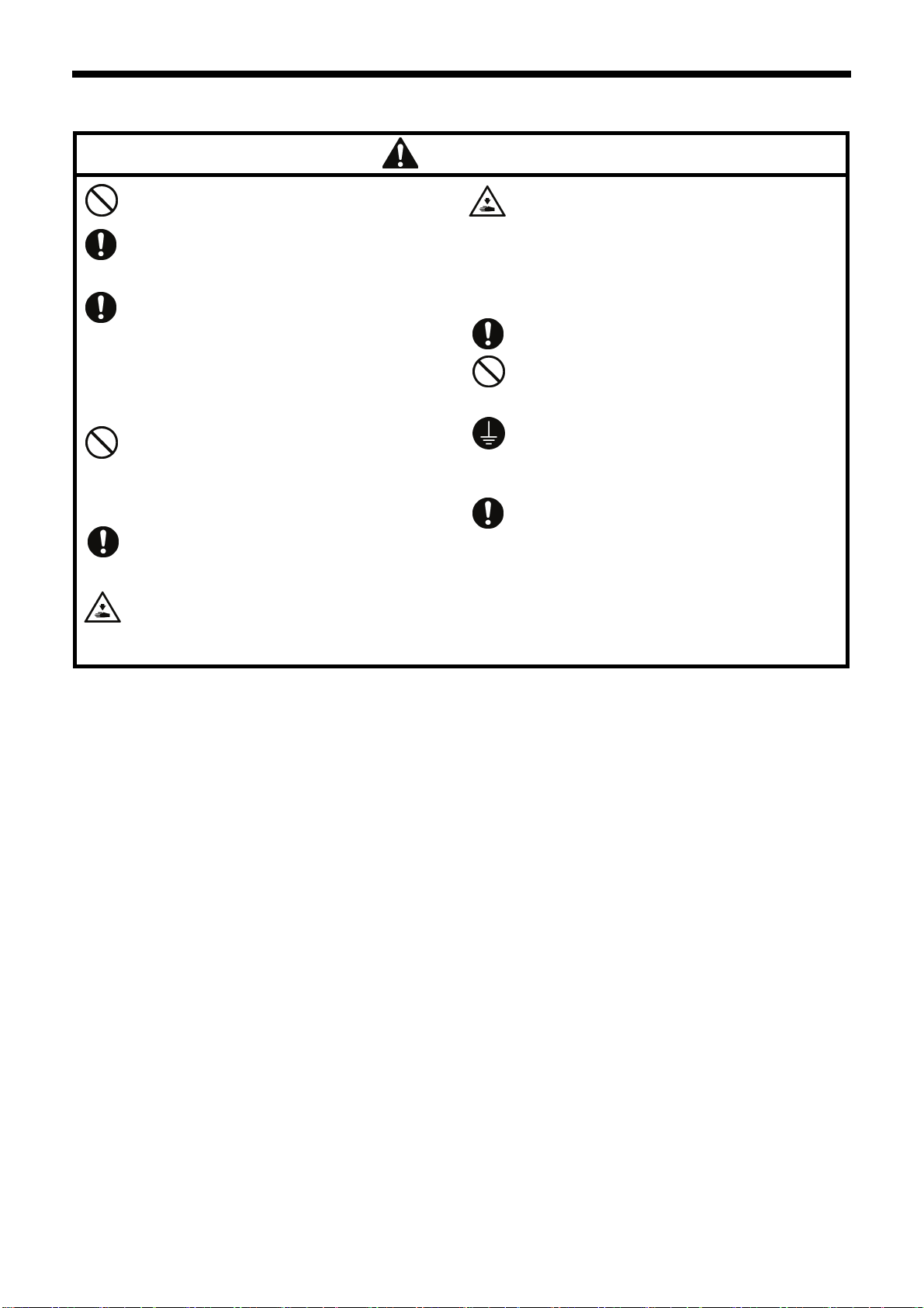
SAFETY INSTRUCTIONS
[1] Safety indications and their meanings
This instruction manual and the indications and symbols that are used on the machine itself are provided in order to ensure
safe operation of this machine and to prevent accidents and injury to yourself or other people.
The meanings of these indications and symbols are given below.
Indications
DANGER
The instructions which follow this term indicate situations where failure to follow the
instructions will result in death or serious injury.
WARNING
CAUTION
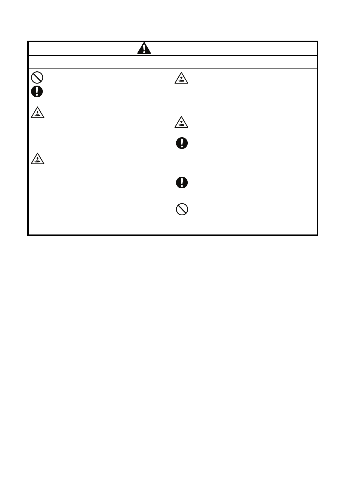
Symbols
・・・・・・
・・・・・・
・・・・・・
The instructions which follow this term indicate situations where failure to follow the
instructions could result in death or serious injury.
The instructions which follow this term indicate situations where failure to follow the
instructions may result in minor or moderate injury.
This symbol ( ) indicates something that you should be careful of. The picture inside the triangle
indicates the nature of the caution that must be taken.
(For example, the symbol at left means “beware of injury”.)
This symbol ( ) indicates something that you must not do.
This symbol ( ) indicates something that you must do. The picture inside the circle indicates the
nature of the thing that must be done.
(For example, the symbol at left means “you must make the ground connection”.)
BAS-341H, BAS-342H
i
Page 6
[2] Notes on safety
Wait at least 5 minutes after turning off the power switch and disconnecting the power cord from the wall outlet
before opening the control box cover. Touching areas where high voltages are present can result in severe injury.
Do not allow any liquids to get onto this sewing machine, otherwise fire, electric shocks or operating problems may
occur.
If any liquid gets inside the sewing machine (machine head or control box), immediately turn off the power and
disconnect the power plug from the electrical outlet, and then contact the place of purchase or a qualified
technician.
DANGER
WARNING
CAUTION
Environmental requirements
Use the sewing machine in an area which is free from
sources of strong electrical noise such as electrical
line noise or static electric noise.
Sources of strong electrical noise may cause
problems with correct operation.
Any fluctuations in the power supply voltage should
be within ±10% of the rated voltage for the machine.
Voltage fluctuations which are greater than this may
cause problems with correct operation.
The power supply capacity should be greater than the
requirements for the sewing machine's power
consumption.
Insufficient power supply capacity may cause
problems with correct operation.
The pneumatic delivery capability should be greater
than the requirements for the sewing machine's total
air consumption.
Insufficient pneumatic delivery capability may cause
problems with correct operation.
The ambient temperature should be within the range
of 5°C to 35°C during use.
Temperatures which are lower or higher than this
may cause problems with correct operation.
The relative humidity should be within the range of
45% to 85% during use, and no dew formation should
occur in any devices.
Excessively dry or humid environments and dew
formation may cause problems with correct operation.
In the event of an electrical storm, turn off the power
and disconnect the power cord from the wall outlet.
Lightning may cause problems with correct operation.
ii
BAS-341H, BAS-342H
Page 7
CAUTION
Installation
Machine installation should only be carried out by a
qualified technician.
Contact your Brother dealer or a qualified electrician
for any electrical work that may need to be done.
The sewing machine weighs approximately 160 kg.
Use equipment such as a crane or hoist when
installing the machine head and adjusting the height
of the table.
If you try to lift the machine head yourself, it may
cause injuries such as back injury.
Do not connect the power cord until installation is
complete. If the foot switch is depressed by mistake,
the sewing machine might start operating and injury
could result.
Hold the machine head with both hands when tilting it
back or returning it to its original position.
In addition, do not subject the machine head to extra
force while it is tilted back. If this is not observed, the
machine head may become unbalanced and fall
down, and serious injury or damage to the sewing
machine may result.
Be sure to connect the ground. If the ground
connection is not secure, you run a high risk of
receiving a serious electric shock, and problems with
correct operation may also occur.
All cords should be secured at least 25 mm away
from any moving parts. Furthermore, do not
excessively bend the cords or secure them too firmly
with staples, otherwise there is the danger that fire or
electric shocks could occur.
Install the safety covers to the machine head and
motor.
If using a work table which has casters, the casters
should be secured in such a way so that they cannot
move.
Use a table with a height of 84 cm or less. If the table
is too high, the machine head may become
unbalanced and fall down, and serious injury or
damage to the sewing machine may result.
Be sure to wear protective goggles and gloves when
handling the lubricating oil and grease, so that they
do not get into your eyes or onto your skin. If the oil
and grease get into your eyes or onto your skin,
inflammation can result.
Furthermore, do not drink or eat the lubricating oil or
grease. They may cause diarrhea or vomiting.
Keep the oil out of the reach of children.
Sewing
To prevent problems, do not use objects with sharp
points to operate the LCD panel.
This sewing machine should only be used by
operators who have received the necessary training
in safe use beforehand.
The sewing machine should not be used for any
applications other than sewing.
Be sure to wear protective goggles when using the
machine.
If goggles are not worn, there is the danger that if a
needle breaks, parts of the broken needle may enter
your eyes and injury may result.
Turn off the power switch at the following times. If the
foot switch is depressed by mistake, the sewing
machine might start operating and injury could result.
• When replacing the bobbin and needle
• When not using the machine and when leaving the
machine unattended
Cleaning
Turn off the power switch before carrying out
cleaning. If the foot switch is depressed by mistake,
the sewing machine might start operating and injury
could result.
If using a work table which has casters, the casters
should be secured in such a way so that they cannot
move.
Attach all safety devices before using the sewing
machine. If the machine is used without these
devices attached, injury may result.
Do not touch any of the moving parts or press any
objects against the machine while sewing, as this
may result in personal injury or damage to the
machine.
If an error occurs in machine operation, or if abnormal
noises or smells are noticed, immediately turn off the
power switch. Then contact your nearest Brother
dealer or a qualified technician.
If the machine develops a problem, contact your
nearest Brother dealer or a qualified technician.
Be sure to wear protective goggles and gloves when
handling the lubricating oil and grease, so that they
do not get into your eyes or onto your skin. If the oil
and grease get into your eyes or onto your skin,
inflammation can result.
Furthermore, do not drink or eat the lubricating oil or
grease. They may cause diarrhea or vomiting.
Keep the oil out of the reach of children.
BAS-341H, BAS-342H
iii
Page 8
CAUTION
Maintenance and inspection
Maintenance and inspection of the sewing machine
should only be carried out by a qualified technician.
Ask your Brother dealer or a qualified electrician to
carry out any maintenance and inspection of the
electrical system.
Turn off the power switch and disconnect the power
cord before carrying out the following operations. If
the foot switch is depressed by mistake, the sewing
machine might start operating and injury could result.
• Inspection, adjustment and maintenance
• Replacing consumable parts such as the rotary
hook
Disconnect the air hoses from the air supply and wait
for the needle on the pressure gauge to drop to “0”
before carrying out inspection, adjustment and repair
of any parts which use the pneumatic equipment.
Hold the machine head with both hands when tilting it
back or returning it to its original position.
In addition, do not subject the machine head to extra
force while it is tilted back. If this is not observed, the
machine head may become unbalanced and fall
down, and serious injury or damage to the sewing
machine may result.
If the power switch needs to be left on when carrying
out some adjustment, be extremely careful to observe
all safety precautions.
When replacing parts and installing optional
accessories, be sure to use only genuine Brother
parts.
Brother will not be held responsible for any accidents
or problems resulting from the use of non-genuine
parts.
If any safety devices have been removed, be
absolutely sure to re-install them to their original
positions and check that they operate correctly before
using the machine.
To prevent accidents and problems, do not modify
the machine yourself.
Brother will not be held responsible for any accidents
or problems resulting from modifications made to the
machine.
iv
BAS-341H, BAS-342H
Page 9
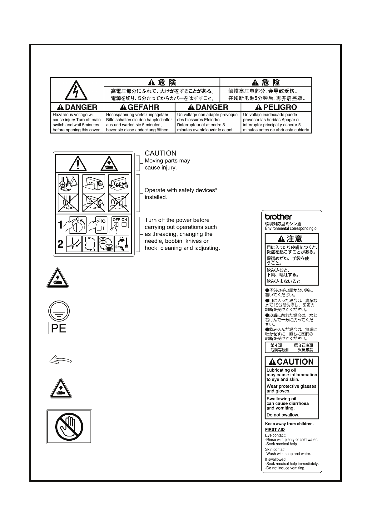
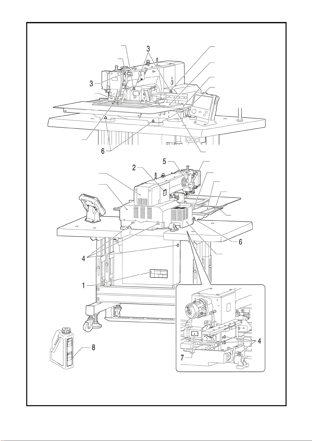
[3] Warning labels
The following warning labels appear on the sewing machine.
Please follow the instructions on the labels at all times when using the machine. If the labels have been removed or are
difficult to read, please contact your nearest Brother dealer.
1
2
3
4
Be careful to avoid injury from moving parts.
Be sure to connect the ground.
If the ground connection is not secure, you run a high
risk of receiving a serious electric shock, and problems
with correct operation may also occur.
.
*Safety devices
Devices such as eye guard, finger guard,
thread take-up cover, motor cover,
X motor cover, rear cover, solenoid cover,
inner cover, outer cover, fixed cover and
gas spring support cover
8
5
6
7
Direction of operation
Be careful not to get your hand caught when tilting back
the machine head and returning it to its original position.
Do not hold, otherwise problems with
operation or injury may occur.
BAS-341H, BAS-342H
v
Page 10
Eye guard
Rear cover FL
Thread take-up cover
Rear cover FR
Inside cover R
Middle cover
Outside cover
Finger guard
Fixed cover
Solenoid cover
Motor cover
Rear cover
Inside cover L
Middle cover
Outside cover
Fixed cover
X motor cover
vi
3461B
BAS-341H, BAS-342H
Page 11

CONTENTS
1. NAMES OF MAJOR PARTS ....... 1
2. USEFUL FUNCTIONS FOR
OPTIMUM SEWING....................
3. INSTALLATION...........................
3-1. Table processing diagram ........................... 4
3-2. Installing the control box.............................. 5
3-3. Installing the oil pan and support
lever base.................................................... 6
3-4. Installing the machine head......................... 6
3-5. Tilting back and returning
the machine head........................................ 7
3-6. Installing the gas spring............................... 8
3-7. Installing the LCD panel .............................. 9
3-8. Installing the solenoid valve assembly ........ 10
3-9. Connecting the air tubes.............................. 10
3-10. Installing the air hose................................. 10
3-11. Installing the two-pedal foot switch............ 11
3-12. Connecting the cords................................. 11
3-13. Connecting the ground wire ...................... 15
3-14. Securing the cords and air tubes............... 16
3-15. Connecting the power cord ....................... 17
3-16. Installing the eye guard .............................20
3-17. Installing the cotton stand.......................... 20
3-18. Lubrication................................................. 21
3-19. Checking the machine head switch........... 22
2
3
4-7. Starting up....................................................30
4-8. Setting 2-step operation for the
work clamp ..................................................31
5. USING THE LCD PANEL
(BASIC OPERATIONS)...............
5-1. Name and function of each
LCD panel item ..........................................32
5-1-1. Main names and functions.....................32
5-1-2. Home screen .........................................32
5-1-3. Sewing operation screen.......................33
5-2. Parameter setting method............................34
5-3. Copying programs........................................37
5-4. Checking the sewing pattern........................38
5-5. Setting the work clamp lift amount...............39
32
6. USING STORAGE MEDIA........... 42
6-1. Notes on handling........................................42
6-2. Importing and exporting data .......................42
6-3. Selecting and importing sewing data ...........44
7. SEWING.......................................45
7-1. Sewing .........................................................45
7-2. Using the STOP switch................................46
4. PREPARATION BEFORE
SEWING......................................
4-1. Installing the needle..................................... 23
4-2. 2-pedal foot switch operation method ......... 23
4-3. Threading the upper thread......................... 24
4-4. Winding the lower thread............................. 26
4-5. Installing the bobbin case............................ 27
4-6. Thread tension............................................. 28
4-6-1. Lower thread tension............................. 28
4-6-2. Upper thread tension............................. 29
23
BAS-341H, BAS-342H
Page 12
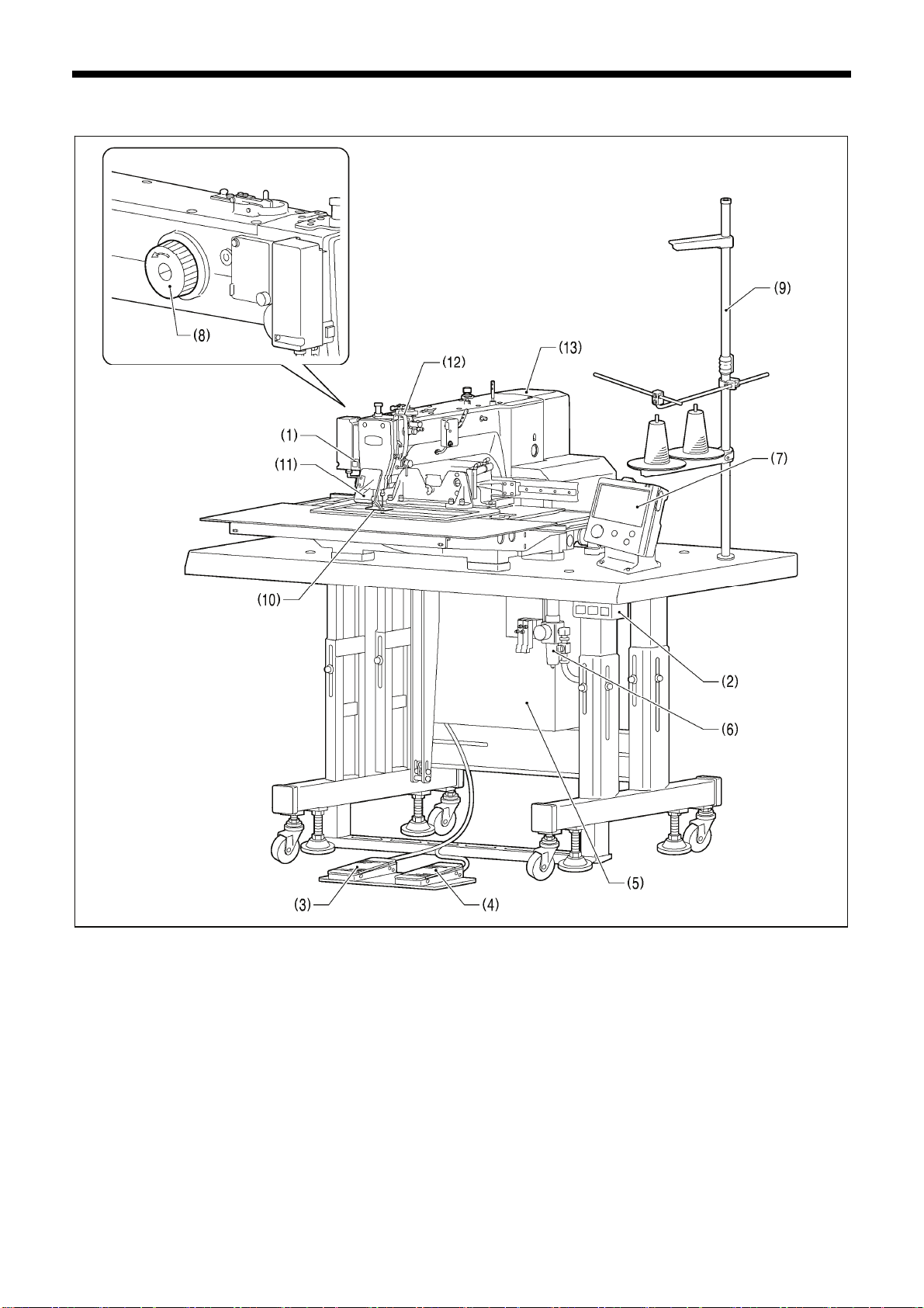
1. NAMES OF MAJOR PARTS
1. NAMES OF MAJOR PARTS
(1) STOP switch
(2) Power switch (10) Finger guard
(3) Work clamp switch (11) Eye guard
(4) Start switch (12) Thread take-up cover
(5) Control box (13) Motor cover
(6) Solenoid valve
(7) LCD panel
(8) Pulley
(9) Cotton stand
Safety devices:
3462B
1
BAS-341H, BAS-342H
Page 13
2. USEFUL FUNCTIONS FOR OPTIMUM SEWING
2. USEFUL FUNCTIONS FOR OPTIMUM SEWING
Easy threading in threading mode
Page 24-25
When using threading mode for threading, the tension
discs will open so that the thread can be threaded
more easily.
Furthermore, threading mode is safe because the
sewing machine will not start even when the start
switch is depressed.
Presser foot height can be set easily using the
LCD panel or the control panel
Page 39-41
The height of the presser foot can be set simply by
entering a numeric value at the LCD panel or the
control panel, without the need for tools.
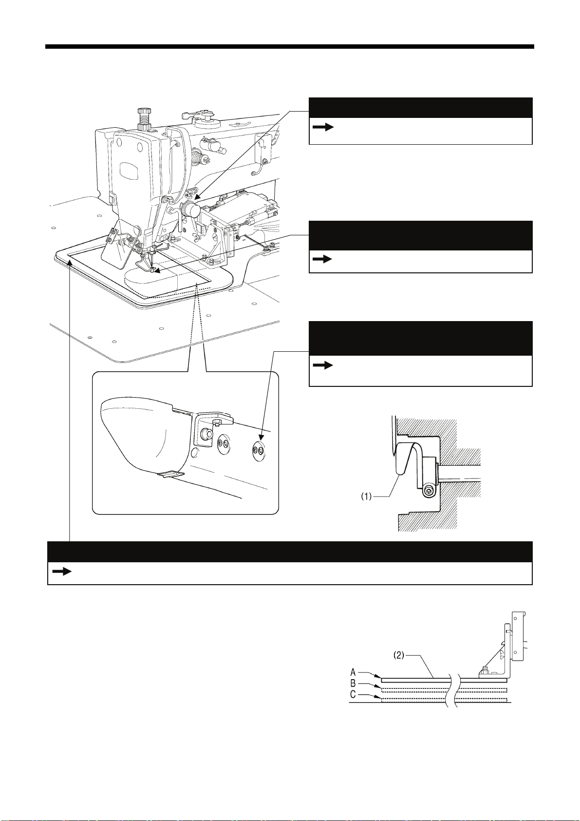
The driver needle guard (1) can be adjusted easily
and within close reach without tilting back the
machine head.
Work clamp lowering operation
4-8. Setting 2-step operation for the work clamp
You can select one of two different types of dropping operation for
the work clamp (2) by changing memory switch settings.
<Work clamp dropping in one step>
When the work clamp switch is depressed, the work clamp (2)
drops in one movement from its highest position A to its lowest
position C.
<Work clamp dropping in two steps>
1. When the work clamp switch is depressed to the 1st step, the
work clamp (2) drops from its highest position A to the
intermediate position B.
2. When the work clamp switch is then depressed to the 2nd
step, the work clamp (2) drops to its lowest position C.
Adjusting the driver needle guard is simple
and within close reach.
Instruction Manual (*1)
7-6. Adjusting the driver (needle guard) position
3590B
2555Q
4057M
(*1) Please download the Instruction Manual from our web site.
BAS-341H, BAS-342H
2
Page 14
3. INSTALLATION
3. INSTALLATION
CAUTION
Machine installation should only be carried out
by a qualified technician.
Contact your Brother dealer or a qualified
electrician for any electrical work that may need
to be done.
The sewing machine head weighs approximately
160 kg.
Use equipment such as a crane or hoist when
installing the machine head and adjusting the
height of the table.
If you try to lift the machine head yourself, it may
cause injuries such as back injury.
Do not connect the power cord until installation is
complete.
If the foot switch is depressed by mistake, the
sewing machine might start operating and injury
could result.
If using a work table which has casters, the
casters should be secured in such a way so that
they cannot move.
Use a table with a height of 84 cm or less. If the
table is too high, the machine head may become
unbalanced and fall down, and serious injury or
damage to the sewing machine may result.
Hold the machine head with both hands when
tilting it back or returning it to its original position.
In addition, do not subject the machine head to
extra force while it is tilted back. If this is not
observed, the machine head may become
unbalanced and fall down, and serious injury or
damage to the sewing machine may result.
All cords should be secured at least 25 mm away
from any moving parts. Furthermore, do not
excessively bend the cords or secure them too
firmly staples, otherwise there is the danger that
fire or electric shocks could occur.
Be sure to connect the ground. If the ground
connection is not secure, you run a high risk of
receiving a serious electric shock, and problems
with correct operation may also occur.
Install the safety covers to the machine head and
motor.
3
BAS-341H, BAS-342H
Page 15
3. INSTALLATION
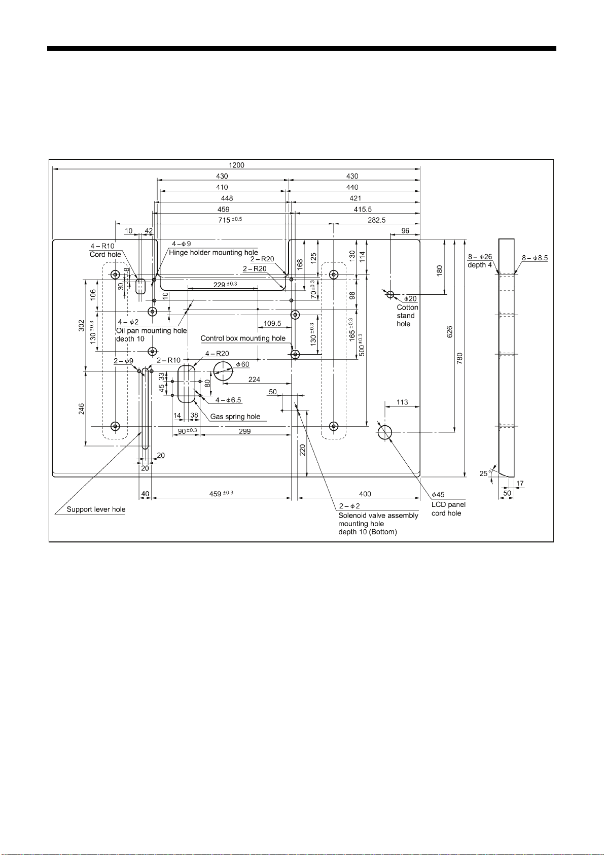
3-1. Table processing diagram
・ The thickness of the table should be at least 50 mm, and it should be strong enough to bear the weight and
vibration of the sewing machine.
・ If using casters, use ones which can bear the total weight of sewing machine and table.
・ Check that the control box is at least 10 mm away from the leg. If the control box and the leg are too close together,
it may result in incorrect sewing machine operation.
3635B
BAS-341H, BAS-342H
4
Page 16
3. INSTALLATION
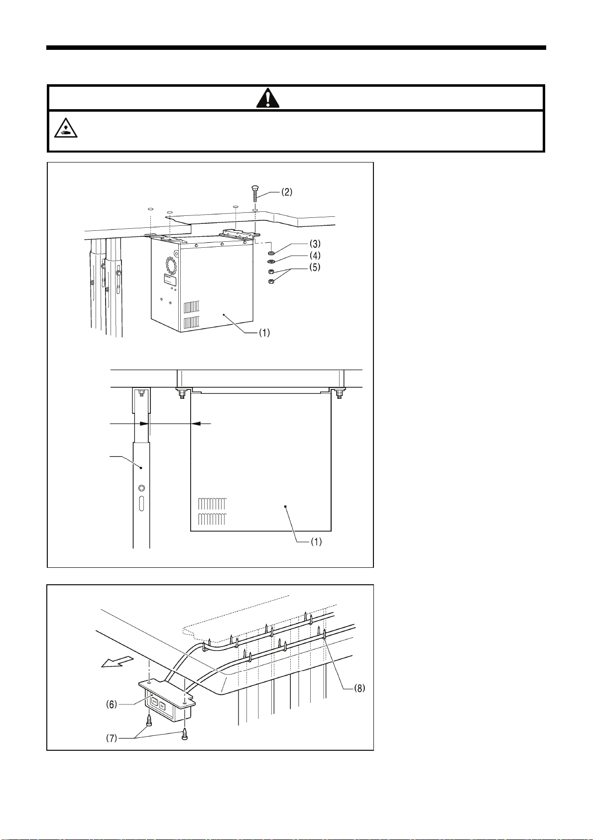
3-2. Installing the control box
The control box is heavy, so installation should be carried out by two or more people.
In addition, take steps to make sure that the control box does not fall down.
If this is not done, injury to feet or damage to the control box may result.
CAUTION
3606B
10mm or more
Leg
Operator
3599B
3608B
(1) Control box
(2) Bolts [4 pcs.]
(3) Plain washers [4 pcs.]
(4) Spring washers [4 pcs.]
(5) Nuts [8 pcs.]
NOTE:
Check that the control box (1) is
at least 10 mm away from the leg.
If the control box (1) and the leg
are too close together, it may
result in incorrect sewing machine
operation.
(6) Power switch
(7) Wood screws [2 pcs.]
(8) Staples [7 pcs.]
NOTE:
Take care when tapping in the
staples (8) to make sure that they
do not pierce the power cord.
5
BAS-341H, BAS-342H
Page 17
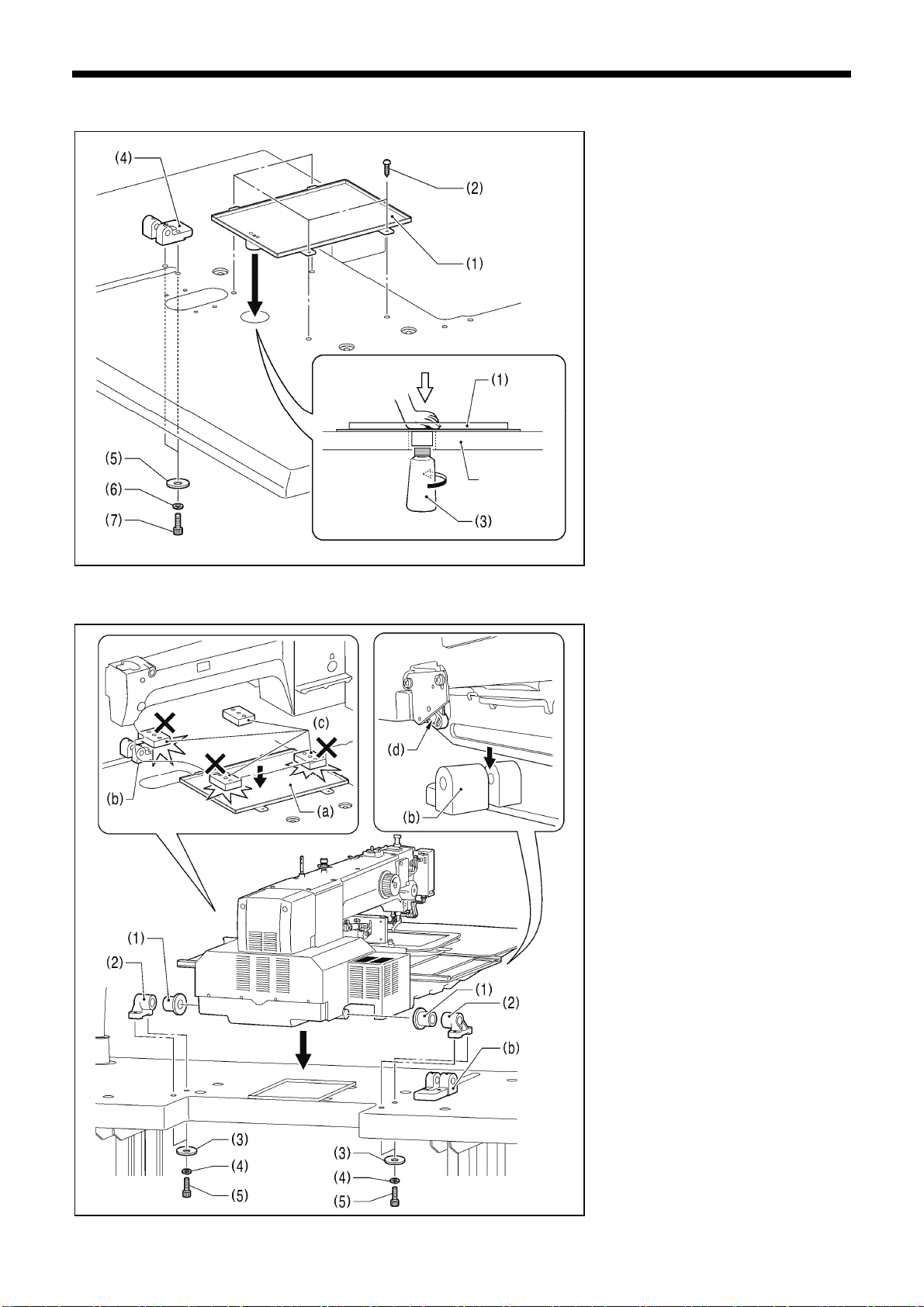
3-3. Installing the oil pan and support lever base
Table
3964M
3. INSTALLATION
(1) Oil pan
(2) Wood screws [4 pcs.]
(3) Oiler
(4) Support lever base
(5) Plain washers [2 pcs.]
(6) Spring washers [2 pcs.]
(7) Bolts [2 pcs.]
3-4. Installing the machine head
2585B
1. Place the machine head onto the
table.
NOTE:
・ Use a crane or hoist to install the
sewing machine.
・ Be careful of the following when
lowering the machine head onto the
table.
! Do not let any cords get clamped
between the machine head and
the table.
! Do not place the machine head
cushion (c) on top of the oil pan
(a) or the support lever base (b).
! Do not let the side (d) of the
machine head switch lever touch
the support lever base (b).
(1) Rubber bushes (2 pcs.)
(2) Hinge holders (2 pcs.)
(3) Plain washers [4 pcs.]
(4) Spring washers [4 pcs.]
(5) Bolts [4 pcs.]
(Continued on next page)
BAS-341H, BAS-342H
6
Page 18
3. INSTALLATION
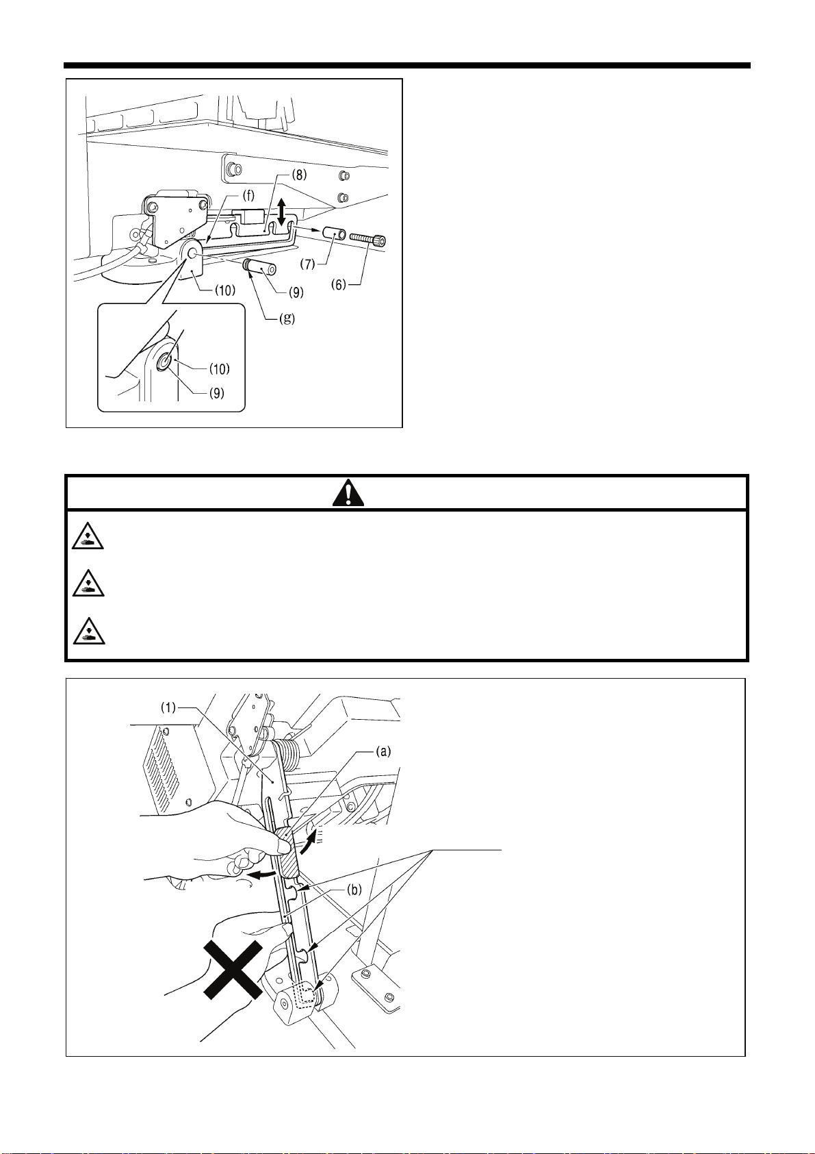
2. After placing the machine head onto the table, remove the
bolt (6) and the spacer (7).
* The bolt (6) and the spacer (7) are necessary for
securing the support lever (8) when the machine head is
removed from the table, so keep them in a safe place.
3. Pass the support lever shaft (9) through the hole in the
support lever base (10) and through the groove (f) in the
support lever (8), and push it in until it is flush with the
surface of the support lever base (10).
* Be sure to insert so that the groove (g) in the support
lever shaft (9) faces in the direction shown in the
illustration.
Flush
* If it is difficult to pass the support lever shaft (9) through
the groove (f) in the support lever (8), move the end of
the support lever (8) up and down while passing the
support lever shaft (9) through.
3601B
3-5. Tilting back and returning the machine head
CAUTION
Hold the machine head with both hands when tilting it back or returning it to its original position.
In addition, do not subject the machine head to extra force while it is tilted back. If this is not observed, the machine head
may become unbalanced and fall down, and serious injury or damage to the sewing machine may result.
Always be sure to engage the stopper of the support lever (1) when tilting back the machine head.
If the stopper is not engaged, the machine head may return to its original position and your hands may get caught and
injury may result.
When disengaging the stopper, hold it by the knob (a).
If you hold at the place indicated by (b), your hand will get caught between the support lever (1) and the table when the
machine head is returned to its original position and injury will result.
Disengaging
the stopper
Engaging
the stopper
The machine head can be tilted
back and returned to one of three
heights.
3967M
7
BAS-341H, BAS-342H
Page 19

3-6. Installing the gas spring
3466B
Crane or hoist
Engaging
the stopper
3. INSTALLATION
Disengaging
the stopper
1. Tilt back the machine head, and then secure the support lever (1) at stopper position (a).
(Refer to "3-5. Tilting back and returning the machine head".)
NOTE: Use equipment such as a crane or hoist to tilt back the machine head.
2. Tighten the two set screws (2) to secure the support lever shaft (3).
Be sure to install so that
the side with “UP” on it is
facing upward.
(10) Gas spring shaft D
(11) Plain washers [2 pcs.]
(12) Retaining rings E [2 pcs.]
(13) Bolts [4 pcs.]
(14) Plain washers [4 pcs.]
(15) Spring washers [4 pcs.]
(16) Nuts [4 pcs.]
(17) Gas spring shaft U
(18) Set screw
* After installing the gas spring (8), gently
Note that the L and R
shapes are different.
2915B
3. Install the gas spring (8).
(4) Gas spring holders [L and R]
(5) Spacer
(6) Bolt
(7) Nut
(8) Gas spring
(9) Shaft collars [2 pcs.]
return the machine head to its original
position.
(Refer to "3-5. Tilting back and returning
the machine head".)
BAS-341H, BAS-342H
8
Page 20

3. INSTALLATION
3-7. Installing the LCD panel
3574B
(1) Cradle
(2) Rubber cushion
(3) Wood screws [4 pcs.]
(4) Setting plate
(5) Flat screws [4 pcs.]
(6) LCD panel
(7) Staples [2 pcs.]
・ Pass the cord of the LCD panel (8)
through the table hole, and then
insert it into the (PANEL) connector
(9) on the side of the control box.
・ Tighten the four wood screws (3) so
that the thickness of the rubber
cushion (2) is 5 mm.
9
BAS-341H, BAS-342H
Page 21

3-8. Installing the solenoid valve assembly
3-9. Connecting the air tubes
Plugs 4
Connect as shown in
the illustration while
checking the marks.
Branch unions Y
2562B
3. INSTALLATION
Install underneath the work table. (Refer
to "3-1. Table processing diagram" for the
installation positions.)
(1) Solenoid valve assembly
(2) Washers [2 pcs.]
(3) Wood screws [2 pcs.]
NOTE:
Make sure that the solenoid valve
assembly does not touch the control
box or the leg of the table.
2563B
3-10. Installing the air hose
Close
Open
2564B
BAS-341H, BAS-342H
1. Close the cock (1).
2. Turn the nut (3) at the end of the air hose (2) and connect it
to the valve (4).
3. Open the cock at the compressor.
* Check that no air is leaking from the connection of the
valve (4) and air hose (2).
4. Open the cock (1).
(The meter pointer will turn clockwise.)
NOTE:
Turn the cock (1) gently to open it.
5. Adjust the air pressure. (Refer to "7-18. Adjusting the speed
controller" in the Instruction Manual.)
10
Page 22

3. INSTALLATION
3-11. Installing the two-pedal foot switch
3530B
(1) Two-pedal foot switch
(2) Conversion harness
Connect the connector for the two-pedal foot switch (1) to the
conversion harness (2). Insert the conversion harness (2) into
the P15 (PEDAL) connector on the main P.C. board. (Refer to
"3-12. Connecting the cords".)
* Be sure to make the ground connection. (Refer to “3-13.
Connecting the ground wire”.)
<Two-pedal foot switch operating method>
When the work clamp switch (left) is depressed, both work
clamps are lowered, and when the start switch (right) is
depressed, the sewing machine starts sewing.
* The work clamp lowering method can be changed using
memory switch No. 002. (Refer to "2-2. List of memory switch
settings" in the "LCD Panel/Operation Panel" Instruction
Manual.) (*1)
Work clamp switch (2-step)
Start switch
4923Q
3-12. Connecting the cords
1. Remove the cover of the control box.
2. Loosen the two screws (1), and then
3. Pass the bundle of cords from the
4. Securely connect the connectors as
NOTE:
(*1) Please download the "LCD Panel/Operation Panel" Instruction Manual from our web site.
3568B
open the cord presser plate (2) in the
direction of the arrow.
machine head through the hole in
the table, and then pass it through
the hole in the control box
together with the solenoid valve.
indicated in the table.
(Refer to next page)
・ Check that the connector is facing
the correct way, and then insert it
firmly until it locks into place.
・ Secure the cables with cable ties
and cord clamps, while being careful
not to pull on the connector.
11
BAS-341H, BAS-342H
Page 23

3. INSTALLATION
< Main P. C. board >
Lock the cord
clamp securely.
<Removal>
Press the tab.
<Securing>
3672B
X pulse motor encoder [5-pin] White P17 (X-ENC) (2)
Y pulse motor encoder [5-pin] Blue P18 (Y-ENC) (2)
Work clamp pulse motor encoder [5-pin] Black P19 (P-ENC) (2)
Machine head switch [3-pin] P14 (HEAD-SW) (2)
Conversion harness [7-pin] White P15 (PEDAL) (2)
Machine head memory [6-pin] P16 (HEAD-M) (2)
Thread trimmer solenoid [6-pin] P2 (SOL1) (1)
Digital tension solenoid / Tension release solenoid [4-pin] P3 (SOL2) (1)
X pulse motor [4-pin] White P21 (XPM) (1)
Y pulse motor [4-pin] Blue P22 (YPM) (1)
Work clamp pulse motor [4-pin] Black P23 (PPM) (1)
Home position sensor [12-pin] White P8 (SENSOR1) (2) (3)
STOP switch [6-pin] White P9 (HEAD) (2) (3)
Valve harness [12-pin] P35 (EX-OUT1) (2) (3)
Upper thread breakage detector [2-pin] White P36, P9(HEAD) (2) (3)
Fan [6-pin] P7 (SENSOR2) (2) (3)
Connectors
Connection location on
main P. C. board
Cord clamps /
cable ties
NOTE: Route the X, Y and work clamp pulse motor harnesses so that they do not touch the power supply P.C. board at
the bottom of the control box.
BAS-341H, BAS-342H
12
Page 24

3. INSTALLATION
< Motor P. C. board >
3576B
Lock the cord clamps
securely.
Connectors
Upper shaft motor [4-pin] (UVW) (4)
Synchronizer [10-pin] P11 (SYNC) (2) (3)
Connection location on
motor P. C. board
Cord clamps
13
5. Close the cord presser plate (6) in the direction of the white
arrow, and secure it by tightening the two screws (5).
NOTE:
Close the cord presser plate (6) securely so that no
foreign objects, insects or small animals can get inside
the control box.
6. Check that the cords do not get pulled, and then gently return
the machine head to its original position.
3538B
BAS-341H, BAS-342H
Page 25

<LCD panel>
3578B
3. INSTALLATION
(PANEL)
Connector D-sub connector
LCD panel [9-pin] (PANEL)
BAS-341H, BAS-342H
14
Page 26

3. INSTALLATION
3-13. Connecting the ground wire
CAUTION
Be sure to connect the ground. If the ground connection is not secure, you run a high risk of receiving a
serious electric shock, and problems with correct operation may also occur.
(1) Ground wire from the machine head
(2) Ground wires from two-pedal foot switch harnesses (2 wires)
3579B
• Tighten the control box cover with the six screws. Check that the cords are not clamped by the cover at this time.
NOTE: Make sure that the ground connections are secure in order to ensure safety.
15
BAS-341H, BAS-342H
Page 27

3-14. Securing the cords and air tubes
3. INSTALLATION
< Perspective view from above table >
Leg
Control box
Table
Solenoid valve
assembly
3654B
3600B
Secure the air tubes (a) and the
solenoid valve assembly cord (b)
together underneath the table with
the three cord holders (1).
(1) Cord holders [3 pcs.]
(2) Wood screws [3 pcs.]
Checking the cords>
<
1. Gently tilt back the machine head.
(Refer to "3-5. Tilting back and
returning the machine head".)
2. Check that none of the cords are
being pulled.
3. Return the machine head to its
original position.
4. Close the cord presser plate (3) in the
direction of the arrow, and secure it by
tightening the two screws (4).
NOTE:
Close the cord presser plate (3)
securely so that no foreign objects,
insects or small animals can get
inside the control box.
5. Secure the cover of the control box by
tightening the eight screws (5).
Check that the cords are not clamped
by the cover at this time.
BAS-341H, BAS-342H
16
Page 28

3. INSTALLATION
3-15. Connecting the power cord
CAUTION
Be sure to connect the ground. If the ground connection is not secure, you run a high risk of receiving a serious electric
shock, and problems with correct operation may also occur.
Leg
Control
box
Connect cords that match the voltage
specifications.
< EU specifications>
(1) Filter box
(2) Screws [4 pcs.]
(3) Staples [4 pcs.]
(4) Power cord
1. Attach an appropriate switch and cable
to the power cord (4). (The green and
yellow wire is the ground wire.)
2. Insert the power plug into a
properly-grounded electrical outlet.
NOTE:
• Take care when tapping in the staples
(3) to make sure that they do not pierce
the cords.
• Do not use extension cords, otherwise
machine operation problems may
result.
17
Green and yellow wire (ground wire)
BAS-341H, BAS-342H
3673B
Page 29

3. INSTALLATION
Operator
3146B
Connect cords that match the voltage
specifications.
<200 V system >
(1) Power switch
(2) Wood screws [2 pcs.]
Green and yellow wire
(ground wire)
3583B
(3) 3-pin power supply connector
(4) Power cord
(5) Staples [5 pcs.]
1. Attach an appropriate plug to the
power cord (4). (The green and yellow
wire is the ground wire.)
2. Insert the power plug into a
properly-grounded electrical outlet.
NOTE:
• Take care when tapping in the staples
(5) to make sure that they do not pierce
the cords.
• Do not use extension cords, otherwise
machine operation problems may
result.
3. Use the six screws to tighten the cover
of the control box. Check that none of
the cords are being clamped by the
cover at this time.
BAS-341H, BAS-342H
18
Page 30

3. INSTALLATION
Operator
Green and yellow wire
(ground wire)
3146B
3584B
<100 V / 400 V system >
(1) Power switch
(2) Wood screws [2 pcs.]
(3) Transformer box
(4) Transformer box plates [2 pcs.]
(5) Screws [with washer] [4 pcs.]
(6) 3-pin power supply connector
(7) Staples [6 pcs.]
(8) Cord clamps [2 pcs.]
(9) Power cord
1. Attach an appropriate plug to the
power cord (9). (The green and yellow
wire is the ground wire.)
2. Insert the power plug into a
properly-grounded AC power supply.
* The inside of the control box uses
single-phase power.
NOTE:
・ If the ground connection is not secure,
electric shocks, operating errors or
damage to electronic components
such as P.C. boards may occur.
・ Take care when tapping in the staples
(7) to make sure that they do not
pierce the cords.
・ Do not use extension cords, otherwise
machine operation problems may
result.
3. Use the six screws to tighten the cover
of the control box. Check that none of
the cords are being clamped by the
cover at this time.
19
BAS-341H, BAS-342H
3585B
Page 31

3-16. Installing the eye guard
Attach all safety devices before using the sewing machine.
If the machine is used without these devices attached, injury may result.
3. INSTALLATION
CAUTION
(1) Bolt (loosen)
(2) Eye guard (tilt forward)
(3) Eye guard assembly
(4) Plain washers [2 pcs.]
(5) Bolts [2 pcs.]
After installing the eye guard assembly
(3), return the eye guard (2) to its original
angle, and then tighten the bolt (1) to
secure it in place.
3048B
3-17. Installing the cotton stand
3533B
(1) Cotton stand
NOTE:
Securely tighten the nut (3) so that
two washers (2) are securely
clamped so that the cotton stand (1)
does not move.
BAS-341H, BAS-342H
20
Page 32

3. INSTALLATION
3-18. Lubrication
Do not connect the power cord until lubrication is complete.
If the foot switch is depressed by mistake, the sewing machine might start operating and injury could result.
Be sure to wear protective goggles and gloves when handling the lubricating oil and grease, so that they do
not get into your eyes or onto your skin. If the oil and grease get into your eyes or onto your skin,
inflammation can result.
Furthermore, do not drink or eat the lubricating oil or grease. They may cause diarrhea or vomiting.
Keep the oil out of the reach of children.
CAUTION
・ The sewing machine should always be lubricated and the oil
supply replenished before it is used for the first time, and
also after long periods of non-use.
・ Use only the lubricating oil <JX Nippon Oil & Energy
Corporation Sewing Lube N10; VG10> specified by Brother.
* If this type of lubricating oil is difficult to obtain, the
recommended oil to use is <Exxon Mobil Essotex SM10;
VG10>.
1. Fill the arm oil tank and the bed oil tank with oil.
NOTE:
Be sure to add more oil when the oil level drops down
to about one-third full in the oil gauge window (1). If the
oil drops below the one-third full level in the oil gauge
window (1), there is the danger that the sewing
machine may seize during operation.
21
2. Pour oil in through the two holes of the shuttle race base
assembly so that the felt (2) is lightly moistened. If it is
difficult to add oil, you can also remove the rubber cap (3)
and pour in the oil through the hole.
NOTE:
3. If using the needle cooler (4), fill it with silicon oil (100
mm2/s).
(Refer to "4-3. Threading the upper thread" for details on
using the needle cooler (4).)
3569B
3531B
3532B
BAS-341H, BAS-342H
• The two pieces of felt (2) should normally project by 0
to 0.5 mm from the hook race. Be careful not to push
in the felt (2) when lubricating.
• If there is no more oil on the felt (2) of the shuttle race
base assembly, problems with sewing may result.
Page 33

3-19. Checking the machine head switch
<If error [E050], [E051] or [E055] is displayed >
If the machine head switch (1) is not turned on, error [E050],
[E051] or [E055] will occur.
Adjust the installation position of the machine head switch (1).
1. Turn off the power.
2. Loosen the two screws (2).
3. Push down the right side of the machine head switch (1) so
4. Turn on the power and check that no error numbers are
3. INSTALLATION
1. If the machine head is tilted back, gently return it to its
original position. (Refer to "3-5. Tilting back and returning
the machine head".)
2. Turn on the power switch.
3. Check that no error numbers appear on the LCD panel.
that the machine head switch (1) turns on, and then tighten
the two screws (2).
displayed.
3989M
BAS-341H, BAS-342H
22
Page 34

4. PREPARATION BEFORE SEWING
4. PREPARATION BEFORE SEWING
4-1. Installing the needle
CAUTION
Turn off the power switch before installing the needle.
If the foot switch is depressed by mistake, the sewing machine might start operating and injury could result.
1. Loosen the set screw (1).
2. Insert the needle (2) in a straight line as far as it will go,
making sure that the long groove on the needle is at the
front, and then securely tighten the set screw (1).
3475B
4-2. 2-pedal foot switch operation method
3991M
Work clamp switch
Start switch
3502B
When the work clamp switch (left side) is depressed, the
intermittent presser foot (1) and the work clamp (2) are
lowered, and when the start switch (right side) is then
depressed, the sewing machine starts operating.
* The work clamp (2) lowering method can be changed
using memory switch No. 002. (Refer to "2-2. List of
memory switch settings" in the "LCD Panel/Operation
Panel" Instruction Manual.) (*1)
(*1) Please download the "LCD Panel/Operation Panel"
Instruction Manual from our web site.
23
BAS-341H, BAS-342H
Page 35

4. PREPARATION BEFORE SEWING
4-3. Threading the upper thread
Thread the upper thread correctly as shown in the illustration below.
* When using threading mode for threading, the tension discs (1) will open so that the thread can be threaded more easily.
(Refer to "Threading mode" on the next page.)
[If using cotton thread or spun thread]
3476B
3477B
• Turn the machine pulley (2) and raise the thread take-up (3) to its highest position before threading the upper thread.
(This will make threading easier and it will prevent the thread from coming out at the sewing start.)
• When threading the thread through the needle, allow a distance of approximately 42 mm between the needle hole and the
end of the thread.
If it is too long, the thread may become tangled, and if it is too short, the thread may pull out at the sewing start.
[If using synthetic thread]
Thread the upper thread
Needle cooler
3586B
BAS-341H, BAS-342H
24
Page 36

4. PREPARATION BEFORE SEWING
<Threading mode>
Threading mode is safe because the sewing machine will not start even when the start switch is depressed.
1
2
Turn on the power.
Touch the Thread key on the screen.
3055B
Threading the thread.
3
Ending threading mode
4
The display will return to the previous screen.
• Work clamp will drop.
• The tension discs will open.
Touch the OK key on the screen.
• The work clamp will return to where it was before
threading mode was started.
25
BAS-341H, BAS-342H
Page 37

4-4. Winding the lower thread
CAUTION
Do not touch any of the moving parts or press any objects against the machine while winding the lower
thread, as this may result in personal injury or damage to the machine.
3587B
3550B
4. PREPARATION BEFORE SEWING
1. Place the bobbin onto the bobbin winder shaft (1).
2. Thread the thread as shown in the illustration, wind the
thread around the bobbin several times, and then press
the bobbin presser arm (2).
3. Turn on the power.
4. Lower the work clamp before depressing the start switch.
Home position detection will be carried out.
5. Touch the Wind key (4) on the screen.
6. The display will switch to the thread winding mode
screen.
7. Check that the needle does not touch the work clamp,
and then lower the work clamp before depressing the
start switch.
8. Keep depressing the start switch until the lower thread
stops being wound onto the bobbin.
9. Once winding of the set amount of lower thread (80 - 90%
of the bobbin capacity) is completed, the bobbin presser
arm (2) will return automatically.
10. Remove the bobbin, hook the thread onto the knife (3),
and then pull the bobbin in the direction of the arrow to
cut the thread.
11. Touch the OK key to return to the previous screen.
(4)
BAS-341H, BAS-342H
26
Page 38

4. PREPARATION BEFORE SEWING
More thread
Less thread
3567B
Case A
Case B
3566B
Adjusting the bobbin winding amount
Loosen the screw (5) and move the bobbin presser (6).
If the thread winds onto the bobbin unevenly
Loosen the set screw (7) and move the bobbin winder
tension assembly (8) up and down to adjust.
* For case A, move the bobbin winder tension assembly (8)
down, and for case B, move it upward.
4-5. Installing the bobbin case
CAUTION
Turn off the power switch before installing the bobbin case.
If the foot switch is depressed by mistake, the sewing machine might start operating and injury could result.
4002M
1. Pull the shuttle race cover (1) downward to open it.
2. While holding the bobbin so that the thread winds to the right, insert the bobbin into the bobbin case.
3. Pass the thread through the slot (2) and pull it out from the thread hole (3).
4. Check that the bobbin turns in the direction of the arrow when the thread is pulled.
5. Pass the thread through the lever thread hole (4), and then pull out approximately 30 mm of thread.
6. Hold the latch on the bobbin case and insert the bobbin case into the rotary hook.
2534Q
30mm
2535Q
27
BAS-341H, BAS-342H
Page 39

r
4-6. Thread tension
[Thread tension reference]
Upper thread #20 or similar
Lower thread #20 or similar
Upper thread tension (N)
[Tension value]
Lower thread tension (N)
4. PREPARATION BEFORE SEWING
1.4 − 1.8
[140 - 180]*1
0.3 − 0.4
Pre-tension (N)
Needle DP x 17 #19
Normal sewing speed 2,000 sti/min
*1 This is the tension value when the pretension is 0.2 N.
0.2 − 0.4
4-6-1. Lower thread tension
Stronge
Weaker
2536Q
Adjust the thread tension to the weakest possible tension by
turning the thread tension nut (1) until the bobbin case will not
drop by its own weight while the thread end coming out of the
bobbin case is held.
BAS-341H, BAS-342H
28
Page 40

4. PREPARATION BEFORE SEWING
4-6-2. Upper thread tension
[Sewing operation screen]
Weaker
Stronger
3598B
(2)
Use the digital tension to adjust the
tension as appropriate for the material
being sewn. (Refer to “Setting the
tension value” below.)
Turn the tension nut (1) (sub-tension) to
adjust so that the upper thread trailing
length is about 42 mm.
Setting the tension value
Touch the △ and ▽ keys (2) on the
sewing operation screen to increase or
decrease the Tension value.
29
BAS-341H, BAS-342H
Page 41

4-7. Starting up
Aligned
3482B
3483B
4. PREPARATION BEFORE SEWING
Before turning on the power, check that the needle bar is
at the needle up stop position.
Turn the pulley (1) in the direction of the arrow until the ridge
at the bottom of the thread take-up (2) is aligned with the
index mark.
Turn on the power.
If a program has been registered, the program number and a
preview of the sewing pattern will be displayed.
No programs are registered at the time of shipment from the
factory, and so "---" is displayed as the program number
(No.).
For details on the sewing data reading method, refer to "6.
USING STORAGE MEDIA".
BAS-341H, BAS-342H
30
Page 42

4. PREPARATION BEFORE SEWING
p
4-8. Setting 2-step operation for the work clamp
Intermediate
osition
1st step
2nd step
1st step
2nd step
4009M
4010M
4011M
When these settings are made, the work clamp (1) can be
lowered in two steps.
1. Set memory switch No. 002 to "1".
(Refer to "2-2. List of memory switch settings" in the "LCD
Panel/Operation Panel" Instruction Manual.)
(*1)
2. With the work clamp (1) raised, loosen the wing screw (2).
3. Move the work clamp stopper (3) up or down to determine
the intermediate position, and then tighten the wing screw
(2) to secure the work clamp stopper (3) in place.
4. Depress the work clamp switch (4) to the 1st step and
check the intermediate position for the work clamp.
5. Depress the work clamp switch (4) to the 2nd step to fully
lower the work clamp.
* 2-step work clamp operation is enabled when memory
switch No. 002 is set to "1".
* Do not set memory switch No. 002 to "2".
<To return the work clamp to one-step operation>
1. Set memory switch No. 002 to "0".
(Refer to "2-2. List of memory switch settings" in the "LCD
Panel/Operation Panel" Instruction Manual.)
(*1)
2. With the work clamp (1) raised, loosen the wing screw (2).
3. Move the work clamp stopper (3) to its highest position,
and then tighten the wing screw (2) to secure the work
clamp stopper (3) in place.
(*1) Please download the "LCD Panel/Operation Panel"
Instruction Manual from our web site.
31
BAS-341H, BAS-342H
Page 43

5. USING THE LCD PANEL (BASIC OPERATIONS)
5. USING THE LCD PANEL (BASIC OPERATIONS)
CAUTION
To prevent problems, do not use objects with sharp points to operate the LCD panel.
5-1. Name and function of each LCD panel item
5-1-1. Main names and functions
(1) Power indicator Illuminates when the power is turned on.
(2) CAUTION indicator Illuminates when an error occurs.
(3) LCD/touch panel This displays messages and touch keys (icons).
(4) HOME key This key is used to return to the home screen.
(5) BACK key This key is used for operations such as returning to the previous step and
canceling settings.
(6) ENTER key This key is used for operations such as confirming settings.
(7) JOG key This key is used when programming sewing data.
(8) SD card slot Insert an SD card.
(9) USB port x 2 Connect a USB memory or other device.
5-1-2. Home screen
3591B
Press the home key to display the home screen.
(1) (2) (3)
(4)
(1) Sewing key Touch to switch to the
(2) Programming key Touch to switch to the
(3) File manager key Touch to switch to the file
(4) Settings key Touch to switch to the
BAS-341H, BAS-342H
sewing operation screen.
programming screen.
manager screen.
setting menu screen.
32
Page 44

5. USING THE LCD PANEL (BASIC OPERATIONS)
5-1-3. Sewing operation screen
・ When the power is turned on while the LCD panel is connected to the sewing machine, this screen is
displayed automatically.
・ If any other screen is being displayed, touch the Sewing key in the home screen to display this screen.
(22)
(23)
(20)
(9)
(11)
(13)
(16)
(3)
(14)
(17)
(27)
(5)
(4)
(10)
(12)
(15)
(18)
(19)
(21)
(26)
(1)
(2)
(8)
(6)
(7)
(28)
(25)
(24)
(1) Production counter key This shows the production counter value.
If you keep pressing this key, the display switches to the setting menu screen.
(2) Lower thread counter key This shows the lower thread counter value.
If you keep pressing this key, the display switches to the setting menu screen.
(3) Screen lock key Press this key to switch the home screen between locked and unlocked.
(4) Copy key Touch to switch to the program copying screen.
(5) Open key Touch to switch to the screen to open the sewing data which is stored in an
external memory.
(6) Type key Touch to select the program type.
(7) Program No. key Touch to display/select the current program number.
(8) Step No. key Touch to display/select the current step number.
(9) Split No. key Touch to display/select the current split number.
(10) Speed key Touch to display/select the sewing speed.
(11) Section No. key Touch to display/select the section number for the digital tension.
(12) Tension key Touch to display/select the digital tension value.
(13) Wiper key Touch to switch the thread wiper on/off.
(14) Thread key Touch to switch the display to the threading screen.
(15) Clamp key Touch to switch to the Adjust Clamp Height setting screen.
(16) Scale Offset key Touch to switch to the Scale/Offset setting screen.
(17) Slow Start key Touch to switch to the Slow Start setting screen.
(18) Wind key Touch to switch to the thread winding screen.
(19) Direct selection keys You can register normal/cycle program numbers into each of these keys.
When you touch a key, the program assigned to that key is selected.
(20) Tension check key Applies tension corresponding to the digital tension value to the upper thread.
Touch once more to stop tension from being applied.
(21) Test key Touch to switch to test mode.
(22) Current stitch number/
Shows the current stitch number and the total number of stitches.
Total number of stitches
(23) Sewing area size Shows the size of the sewing data area.
(24) Sewing data information Shows information about the sewing data.
(25) Preview Shows a preview of the sewing data.
(26) Model name Shows the model name and specifications.
(27) Date and time Shows the current date and time.
(28) Comments Shows comments about the sewing data.
33
BAS-341H, BAS-342H
Page 45

5-2. Parameter setting method
Parameter settings are made at the sewing operation screen.
5. USING THE LCD PANEL (BASIC OPERATIONS)
(1)
(2) (3)
(4)
(5) (6)
Sewing speed
Use the Speed △ and ▽ keys (1) to make the setting.
・Setting range: 200 sti/min - 2800 sti/min 100 sti/min units Initial value: 2000 sti/min
Digital tension
< Basic method of use >
Touch the No. △ or ▽ key (2) to change the section number.
Touch the Tension △ or ▽ key (3) to change the tension value.
・The thread tension value which is set will be applied the next time sewing is carried out.
< Overall correction >
This function is useful if you would like to change the tension values for all programs at once.
Touch the No. △ or ▽ key (2) to set the section number to "ALL".
Touch the Tension △ or ▽ key (3) to change the overall correction value.
The upper thread tension which matches the overall correction value which has been set for the
upper thread tension will be applied during sewing.
・The thread tension value which is set will be applied the next time sewing is carried out.
Thread wiping
Touch the Wiper key (4) to turn the wiper on or off. (The initial setting value is on.)
When the setting is on, the key is displayed in blue.
BAS-341H, BAS-342H
34
Page 46

5. USING THE LCD PANEL (BASIC OPERATIONS)
X/Y-scale, X/Y-offset
Touch the Scale Offset key (5) to display the Scale/Offset setting screen.
(7) (8)
(10) (10)
・X-Scale, Y-Scale (7) 0-400%, 0.1% units
(Limited by available sewing area.)
・X-Offset, Y-Offset (8) 0-(size of sewing machine sewing area) mm, 0.1 mm units
When activating the offset, first lower the work clamp to carry out home position detection.
・Touch the OK key (9) to confirm the setting and return to the previous screen.
・Touch the Reset key (10) to return the setting to the initial value.
Initial values: X/Y-scale = 100%, X/Y-offset = 0 mm
・Touch the Cancel key (11) to return to the previous screen without changing the setting.
(9) (11)
35
BAS-341H, BAS-342H
Page 47

5. USING THE LCD PANEL (BASIC OPERATIONS)
Slow start pattern
Touch the Slow Start key (6) to display the Slow Start setting screen.
(12)
(15)
(13) (14)
・
Touch the or key (12) to adjust the starting-up speed at the sewing start.
△▽
・Touch the OK key (13) to confirm, or touch the Cancel key (14) to return to the sewing operation
screen without changing the setting.
・Touch the Reset key (15) to return the setting to the initial value.
* The smaller the number, the slower the start.
* This is used to stop the thread from pulling out at the sewing start, and at times when skipped stitches
might easily occur.
Lo
1 2 3 4 5 6 7 8 9
Sewing speed for 1st stitch
Sewing speed for 2nd stitch
Sewing speed for 3rd stitch
Sewing speed for 4th stitch
200 200 300 400 400 400 400 600 800
200 300 400 400 500 600 800 1000 1200
300 400 500 600 800 1000 1200 1600 *1
500 600 700 900 1200 1400 *1 *1 *1
*1 Sewing will be carried out at the sewing speed which is set by the parameters.
* For details on the sewing data reading method, refer to "6. USING STORAGE MEDIA".
* When memory switch No. 400 is set to ON, the X-scale, Y-scale, sewing speed and work clamp height can be
recorded separately for each program number.
* When memory switch Mo. 100 is set to ON, slow start patterns can be recorded separately for each program
number.
* For details on memory switches, refer to "2-1. Memory switch setting method" in the "LCD Panel/Operation
Panel" Instruction Manual. (*1)
(*1) Please download the "LCD Panel/Operation Panel" Instruction Manual from our web site.
BAS-341H, BAS-342H
36
Page 48

5. USING THE LCD PANEL (BASIC OPERATIONS)
5-3. Copying programs
[Sewing operation screen]
(1)
Touch the Copy key (1) to switch to the program copying screen.
[Copy screen]
Select the copy source program No. and the copy destination program No.
Touch the OK key to carry out copying. After copying, the display will return to the previous screen.
Touch the Cancel key to return to the previous screen without copying.
37
BAS-341H, BAS-342H
Page 49

5. USING THE LCD PANEL (BASIC OPERATIONS)
5-4. Checking the sewing pattern
Use test feed mode to operate the feed mechanism in order to check the needle movement.
Check that the needle hole does not come out from the frame of the work clamp.
1
The Test key is displayed in blue.
[Sewing operation screen]
1. Touch the Test key at the sewing operation screen.
2. Press the △or ▽ key (1) to set the program number
that you would like to check.
2
Continuous test feed
Work clamp switch
(2-step)
(1)
Start switch
(2)
1. If you lower the work clamp and then depress the
start switch, the feed mechanism will start moving
continuously one stitch at a time.
(The stitch number display will be decremented by
one titch at a time.)
2. When the feed reaches the end of the pattern, it
stops.
・ If you would like to stop the feeding operation,
touch the continuous feed stop key
・ Touch the Move to sewing start key (2) to return
to the sewing start.
.
4923Q
Single stitch check
BAS-341H, BAS-342H
Touch to move back by one stitch.
Touch to move forward by one stitch.
Fast-forward
38
Page 50

5. USING THE LCD PANEL (BASIC OPERATIONS)
5-5. Setting the work clamp lift amount
The settings for the work clamp and intermittent presser foot lift amounts can be changed using the sewing
operation screen.
Only threading mode and intermittent presser foot height setting mode are enabled.
[Sewing operation screen]
(1)
Touch the Clamp key (1) to display the Adjust Clamp Height setting screen.
39
BAS-341H, BAS-342H
Page 51

5. USING THE LCD PANEL (BASIC OPERATIONS)
(2)
(5)
(3)
(6)
(4)
・Work clamp height setting (can only be selected for motor driven-type work clamp)
- Use the Type keys (2) to select "Work Clamp Height".
- If you use the Height keys (3) to change the Height value, the sewing machine's work clamp
will move. (setting range: 15-25 initial value: 20)
- Touch the OK key (4) to confirm, or touch the Cancel key (6) to return to the sewing operation
screen without changing the setting.
- Touch the Reset key (5) to return the value which currently appears in the display to the value
which was first displayed when you switched to the setting screen. The sewing machine's work
clamp will operate according to this value.
・Intermediate work clamp height setting (can only be selected for motor driven-type work clamp)
Selection is only possible when memory switch No. 003 is set to "2".
- Use the Type keys (2) to select "Intermediate Work Clamp Height".
- If you use the Height keys (3) to change the Height value, the sewing machine's work clamp
will move. (setting range: 1-15 initial value: 7)
- Touch the OK key (4) to confirm, or touch the Cancel key (6) to return to the sewing operation
screen without changing the setting.
- Touch the Reset key (5) to return the value which currently appears in the display to the value
which was first displayed when you switched to the setting screen. The sewing machine's work
clamp will operate according to this value.
・Intermittent presser foot height setting
- Use the Type keys (2) to select "Intermittent Presser Foot Height".
- If you use the Height keys (3) to change the Height value, the sewing machine's intermittent
presser foot will move. (setting range: 0.0-10.0 initial value: 5.0)
- Touch the OK key (4) to confirm, or touch the Cancel key (6) to return to the sewing operation
screen without changing the setting.
- Touch the Reset key (5) to return the value which currently appears in the display to the value
which was first displayed when you switched to the setting screen. The sewing machine's
intermittent presser foot will operate according to this value.
BAS-341H, BAS-342H
40
Page 52

5. USING THE LCD PANEL (BASIC OPERATIONS)
Intermittent presser foot operation
During
standby
① Intermittent presser foot lift amount
② Intermittent presser foot height
The settings can be made by the above
operations.
However, set the intermittent presser foot
When
lowered
height to a higher setting than the
intermittent stroke.
* If it is set smaller, the intermittent presser
foot will come into contact with the needle
While
sewing
plate.
③ Intermittent stroke
Refer to “7-15. Adjusting the intermittent
work clamp” in the Instruction Manual
5033Q
when making the adjustment. (*1)
(*1) Please download the Instruction Manual for the sewing machine from our web site.
41
BAS-341H, BAS-342H
Page 53

6. USING STORAGE MEDIA
CAUTION
To prevent problems, do not use objects with sharp points to operate the LCD panel.
6-1. Notes on handling
[SD]
- Compatible cards: SD (max. 2 GB), SDHC (max. 32 GB)
- Compatible file formats: FAT16, FAT32
[USB Memory]
- Compatible file formats: FAT16, FAT32
- Max. size: 32 GB
6-2. Importing and exporting data
6. USING STORAGE MEDIA
1
SD card slot USB port
2
[Home screen]
(1)
[Setting menu screen]
Insert an SD card or USB memory.
NOTE:
・ Make sure that the media is facing the
correct way when inserting it.
・ Always be sure to keep the cover closed
except when inserting and removing the
media.
3660B
3593B
・ Press the home key to display the home screen.
・ Touch the Settings key (1) to switch to the
setting menu screen.
・ If you select "Data Management" -> "Import",
the display switches to the import screen, If you
select "Data Management" -> "Export", it
switches to the export screen.
* If more than one SD card and/or USB memory
is connected, a selection dialog box will be
displayed.
BAS-341H, BAS-342H
42
Page 54

6. USING STORAGE MEDIA
3
[Import screen]
[Export screen]
(2)
Select the items to be imported or exported, and
then touch the OK key (2).
[Items to import]
Sewing Program (all)
Extended Option
Memory Switch
Cycle Programs & User Parameter
* To select and import only part of the sewing data,
refer to the procedure in 6-3.
[Items to export]
Sewing Program (all)
Extended Option
Memory Switch
Cycle Program & User Parameter
Error Log
(2)
43
BAS-341H, BAS-342H
Page 55

6-3. Selecting and importing sewing data
6. USING STORAGE MEDIA
1
SD card slot USB port
2
[Home screen]
[File manager screen]
(1)
Insert an SD card or USB memory.
NOTE:
・ Make sure that the media is facing the
correct way when inserting it.
・ Always be sure to keep the cover closed
except when inserting and removing the
media.
3660B
3593B
・ Press the home key to display the home screen.
・ If you touch the File manager key (1), the
display will switch to the file manager screen.
・ Touch the media key in the top-left corner to
select "SD Card" or "USB Memory". The screen
will then change to display the folder which
contains the sewing data.
3
・Select the files to be imported and then touch the
import key (2)
* If you would like to select multiple files, you can
select files in multiple select mode.
(2)
* For details on other functions, please contact the place of purchase.
.
Touch to switch between multiple
select and single select mode.
BAS-341H, BAS-342H
44
Page 56

7. SEWING
7. SEWING
Do not allow any liquids to get onto this sewing machine, otherwise fire, electric shocks or operating problems may
occur.
If any liquid gets inside the sewing machine (machine head or control box), immediately turn off the power and
disconnect the power plug from the electrical outlet, and then contact the place of purchase or a qualified
technician.
Turn off the power switch at the following times.
If the foot switch is depressed by mistake, the sewing machine might start operating and injury could result.
• When replacing the bobbin and needle
• When not using the machine and when leaving the machine unattended
Do not touch any of the moving parts or press any objects against the machine while sewing, as this may result in
personal injury or damage to the machine.
7-1. Sewing
WARNING
CAUTION
1. Turn on the power.
2. Touch the △ or ▽ key to select the number for the
program to be sewn.
* For details on reading sewing data from SD cards and
USB memory devices, refer to "6-3. Selecting and
importing sewing data".
3. Lower the work clamp (2) and then depress the start
switch (1).
Home position detection will be carried out.
4. Place the materials under the work clamp (2).
5. Depress the work clamp switch (3).
The work clamp (2) will be lowered.
6. Depress the start switch (1).
The sewing machine will start sewing.
3551B
7. After sewing is completed, the thread trimmer will
operate. And then the work clamp (2) will be raised.
Use a work clamp which will hold the material securely
so that it does not slip. If the material slips when using
the standard work clamp and feed plate, process them
so that the material does not slip.
45
3486B
BAS-341H, BAS-342H
Page 57

7. SEWING
7-2. Using the STOP switch
If you press the emergency stop switch (1) to during actual sewing, an error dialog box will be displayed and the sewing
machine will immediately stop.
3487B
(2)
<Clearing>
1. Touch the Reset key (2).
・ The thread will be trimmed, and then the error dialog
box on the screen will disappear and the buzzer will
stop.
2. A dialog box asking you to confirm if you want to
continue sewing will be displayed.
(3) (4)
<Continuing sewing from a stopping point>
If the thread breaks or the lower thread runs out during sewing, you can then continue sewing from the point where the
thread broke or ran out.
1
Touch "Yes" (3) to return to the resewing standby screen.
2
3
(5) (6)
Touch the
to the position where sewing is to be resumed.
When you touch the
by 1 stitch, and when you touch the key (6), the feed will
move forward by 1 stitch.
Depress the start switch.
The sewing machine will start operating and sewing will start.
keys (5) and (6) on the screen to return
key (5), the feed will move backward
start switch
<Returning to the sewing start position without continuing sewing>
If you do not wish to continue sewing, touch "No" (4).
・After home position detection is carried out, the mechanism will return to the sewing start position.
3655B
BAS-341H, BAS-342H
46
Page 58

お手入れや標準調整など、更に詳しい内容は、「取扱説明書」をご覧ください。
取扱説明書、パーツブック、押え板加工図、送り板加工図は、弊社 Web サイトからダウンロードしてください。
For cleaning, standard adjustments and more details, please refer to the download version of the Instruction Manual.
Download the Instruction Manual, Parts Book, work clamp processing diagram and feed plate processing diagram from the
Internet.
保养、标准调整等详细内容,请浏览下载版的使用说明书。
使用说明书、零部件手册、压脚板加工图、送布板加工图请从本公司网站下载。
Para limpiar, realizar ajustes estándar y otros detalles, consulte el manual de instrucciones de la versión de descarga.
Descargue el manual de instrucciones, el libro de partes, el diagrama de procesamiento de trabajos y el diagrama de
procesamiento de la placa de alimentación desde Internet.
日本 / Japan / 日本 / Japón URL: http://www.brother.co.jp/product/ism/index.htm
中国 / China / 中国 / China URL: http://www.brother.cn/cn/ism/ism.html
アジア / Asia / 亚洲 / Asia URL: http://www.brother.com/as_oc/ism/
南北アメリカ / Americas / 美洲 / América URL: http://www.brother-usa.com/Support/
ヨーロッパ、中東、アフリカ /
Europe, Middle East and Africa /
欧洲、中东和非洲 /
Europa, Oriente Próximo y África URL: http://www.brother-industrial.com/
* 製品改良のため、本書の内容の一部がお買い上げの製品と異なる場合がありますのでご了承ください。
* Please note that the contents of this manual may differ slightly from the actual product purchased as a result of product improvements.
* 请注意:由于产品改进,本手册内容可能会与实际购买的产品略有出入。
* Tenga en cuenta que como resultado de mejoras en el producto el contenido de este manual puede variar ligeramente del producto
que ha comprado.
© 2015 Brother Industries, Ltd. All Rights Reserved.
This is the original instructions.
Este es el original de las instrucciones.
SB6436001
使用说明书
BAS-341H, BAS-342H
SB6436-001
2015.07. B (1)
 Loading...