

Page 1
&WinB~W
BAS-341E
INSTRUCTION MANUAL
BAS-342E
C:
OJ~BJUI~mA~
c:
OJ~qijlfl~,
INNER CLAMPING DEVICE (FOR PNEUMATIC)
Please read this manual before using the machine.
Please keep this manual within easy reach for quick reference.
cb\
5,
~~~c
l!lt:9
OW~~
t::ue~
<:It:&
<tee!\, lo
o ffJtt Qflmlt:,
~m
lJ
~<tee!\,
'0
Page 2
1. lti
Of'il:tQiUIC:
1.
Before installation ..... .
······
/A
•
:::1::1
~D-JIJffi~?;(.0)1JJt-~mJI:tQ~(ct~"f'rui;(.-1'
t:ll
/A
t:ll
A •
~
A • Turn
~
s~rdJ~:>Z:b'61JJt-~rmr:t-r:<tC:c!t,\o
• Wait at least 5 minutes after turning
from the wall outlet before opening the face plate
high voltages are present can
fF~O)iiJI~tiiJi;(.-1'~7~tJJt>,
~:>Z:fflfi~fflt>c,
• IJ7-{jt*SjliO)IJ7-:::J
lJ
Z:
(lee!\,
off
ing, otherwise the machine will operate
result
• Close the air cock
the needle
\o
the power switch and disconnect the power cord before carrying out troubleshoot-
in injury.
of
the pressure gauge points
S:V::Jb'fFIJ.JlJZ:I:tb'O)mt~c~O~t"o
~?~B.Dt;,
of
the air supply source, and then open the drain cock
A
fBIII
result in severe injury.
/DANGER
iEll21ffaB~r~,J,nQc,
off
the power switch and disconnecting the power cord
of
~7~tJJO,
the control box. Touching areas where
A 5til /CAUTION
tllt:155~•\,\"r:(tcc!\,\o
t-=LI-1'::J:::J
to
~?~t>IJ7-~-:C:,
if
the treadle is pressed
non.
tUi:175~-\,\Z:,
:itl:tb'~9QC:cb'®O~t"
J±:t.JMo.>mtl"~
by
mistake, which could
to
bleed the air until
:tO)fl
raJ
o
I~
1.
11X
t>
f'il:t
1-1 .
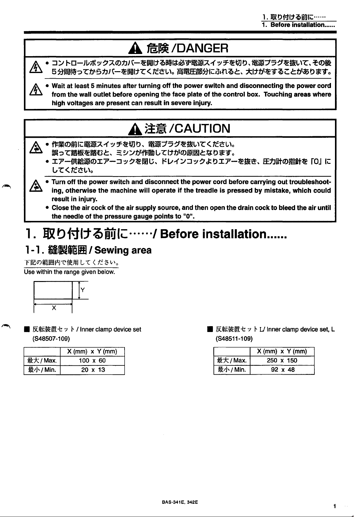
r~[!o:>~lmi*J"t:19!ffl
Use within the range given below.
•
ii*/Max.
Jl'J'/ Min.
tl~i'BBI/
X
&~~111!
(848507-109)
7 r I Inner clamp device set
X (mm) x Y (mm)
~
f.ilt:
Sewing area
L
"l
<
t!.
~
v'o
y
100 X 60
20 X 13
······I
Before installation ..... .
•
&~~111!
(848511-109)
ii*tMax.
ft'J'/ Min.
7 r U Inner clamp device set, L
X (mm) x Y (mm)
250 X 150
92 X 48
BAS-341 E, 342E
1
Page 3
1.
lfRt>MI:t~iUI~······
1. Before installation ..... .
1 -2.
MJ;t.fE~
1 -3. m b
9
~ J ~
I
~JiO)fF
b
-O)Ifil b
15
I How to make the feed plate
~
L.,
I
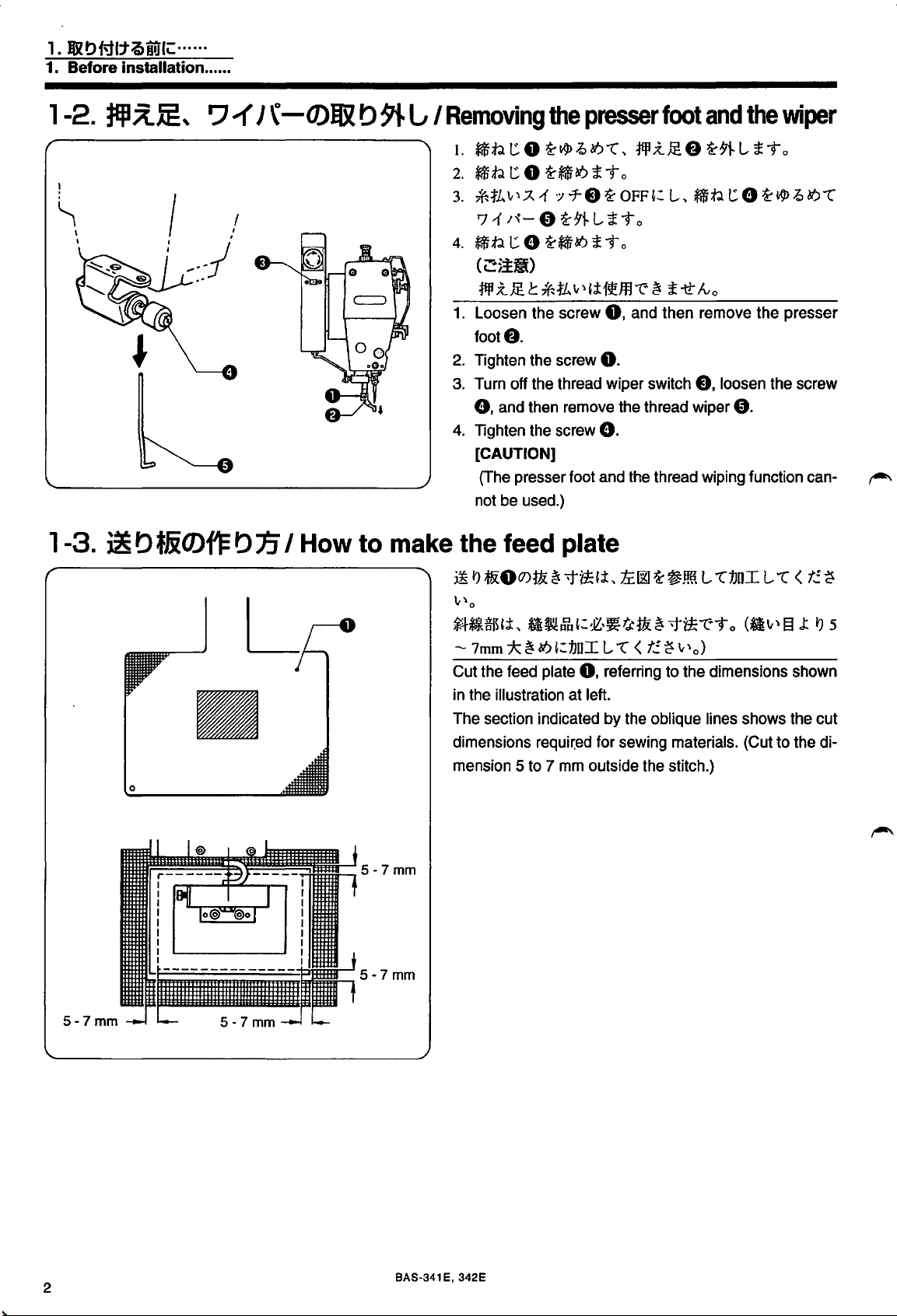
Removing
1.
~t.l
t::
0
2.
~t.l
t::
0
3.
*1L
v-~
.A
'7
1
'"-
4.
~t.l
t::
8
(
c:::~.til)
¥fJ
;t,@ C *1L
1.
Loosen
foot&.
2.
Tighten
3.
Turn
0,
4.
Tighten
[CAUTION]
(The
not
off
and
presser
be
used.)
the screw
the
the
then
the
the
presser
'i-~~9)1.",
'i-~N)
~
-t 0
1 ·:rr 8
e
'i-~N)
screw
thread
screw
'i-91-
L
~
\{\
'j:{5J!ffl
0.
remove
e.
foot
and
'i-
~-to
-t 0
0,
wiper
foot
~.:tJEO
OFF~:
the
'1:
and
switch
thread
the
L,
~
~
-tt"
then
thread
and
the
'i-91-
L
~t.l
t::
8
lvo
remove
8,
loosen
wiper
e.
wiping
function
wiper
~-to
'i-
$
~
N)
1."
the presser
the
screw
can-
r-"·
5-7mm
~
I'J
l&OO)~ ~ >t~'i,
i.!J-it~il!Hi,
- 7mm :k
Cut
the
in
the
The
dimensions
mension 5 to 7 mm
0
5-7mm
*1~&1
~
feed
illustration
section
N)
':1JDI L
plate
at
indicated
requi~ed
tL~
'i-~.lffi
':1l-~~t&:
0,
referring
left.
by
for
outside
1."
<
f!
the
oblique
sewing
the
!i
L
1."1JDI L 1."
-t~-e--t
~
v'o)
to
the
dimensions
lines
materials.
stitch.)
o (*lv'
shows
(Cut
<
13
shown
the
to
the
J:
t!.
~
I')
cut
di-
5
2
BAS-341E, 342E
Page 4
1.
I&t>f'11:t.QiitJ'IC::
1. Before installation
*
~n,&:1'5'Y?hDI
~
~
:foc7
·7
:;_,-
7
~1~ffllJ!l.1
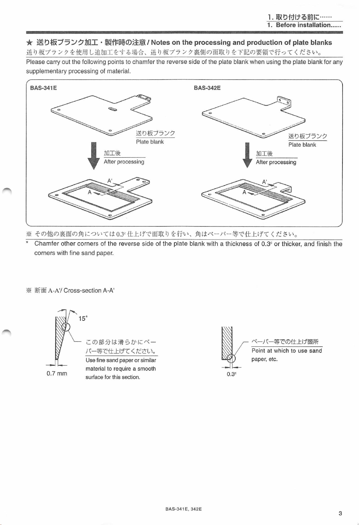
Please carry out the following points to chamfer the reverse side of the plate blank when using the plate blank for any
supplementary processing of
BAS-341E BAS-342E
·
~fl=~0)5.i~l
Jui ~
"t
~
tj)j'fr, ~
material.
Notes
~
if&:7.7 / 7
on
the
processing
?&
1JliJ
and
production
(J)Tiff
~ ~ ~ r~c(J)~~Ji-r:
of
plate blanks
1
:Y?
-c
< t
!.
~
....
..
.... ..
v
'o
Plate blank
1JDI1rt
-
After processing
'
* Chamfer other corners of the reverse side of the
wi
th
corners
*
ltffW
A-A'/
fine sand paper.
Cross-section A-A'
15°
1JDI1rt
-
After processing
'
pl
ate blank with a thickness of 0.3c
Plate blank
or
thicker, and finish the
L.
(])
$ 5}
lei:
5~
s
b'
1;: "'-
; \ -~
c
0.
7mm
f±...tl1-c
Use fine sand paper
material
surface for this section.
to require a smooth
< r
.:
or
similar
c-G
'·
BAS-34
1 E, 342E
"'
-;
\
-~c(J)f±...tlfl!iPJT
Poi nt
at
which
to use sand
paper, etc.
3
Page 5
1.
&OMtt~iUlC:······
1.
Before installation
.•••..
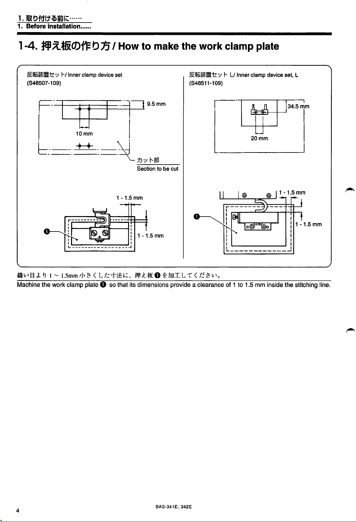
1-4.
tEJI;l~JiO)f'Fb1i
&~~fEliz
(848507-109)
b.---++
I How to make the work clamp plate
'Y !'--/Inner clamp device set
10mm
__
1--fl"':"-~ii----1:
I I
I I
\d
-~
-1.5
mm
1
: 1
1J'Y
!'--$
Section
-1.5
to be cut
mm
&~~~iz
(848511-109)
'Y
~---
1'--
U Inner clamp device set, L
20mm
_______
I
'--------'
--------------~
---,
34.5mm
I
I
,_j
I
I
I
I
I
I
I
I
Machine
the
work
clamp
plate 0
so
that
its
dimensions provide a clearance
of 1 to
1.5
mm
inside
the
stitching
line.
4
BAS-341 E, 342E
Page 6

2.
ijX
t>
f11:t1J
2. INSTALLATION
2.
2-1 .
* Close the air coc k and make sure that the presser assembly moves slightly before carrying out the installation.
•
QXbigl:tJJ
fEJix~UH*
*
:x.
7 -~ ·:;
&!Iii~~
-t
7
·;;
~
1--
/INSTALLATION
I Presser unit
f,M
aty-c,
;jill
X.
J~Jil
I Inner clamp
device
i>"U
<
lWJ
set (S48507
<
~
7(tH:
-1
l
09)
--c
i>'
t?
q:y
-=>
--c < t:.· ~ "'
o
I.
:f1ll
;{_..@
SELO c
2.
*
IJ
;f&:
8
3.
:f1ll;{_
7 7
1. Remove work clamps (SEL) 0 and (SER)
2. Replace the feed plate E) with the feed plate 0 that was made in accordance with "How to make the feed plate".
3.
Attach the work clamp crank
and 0 respectively.
•
&~i~~
-t
:f1ll
;{_..@
~
'./
7 LA
*
IJ
91-l, 1JDI l
*'-!i
SERf)
0
~;jill
~~
t
.:~
X.JE.*-!
l
IJ
IJ
f)
)'
~
l ;t To
fa
0
1:,
~I&
9i-:f1ll
0.
LA
assembly 0 and the external work clamp foot 0 to the work clamp assembly
·:;
1--
U Inner clamp device set, L (S48511-1 09)
IJ
1
•i'
;{_..@
~t
;t
To
0
~
;j1jl
X.
JE.m
0 1: *
IJ
1-t~t
;t To
f)
I.
;jill;{_..@
2. *
3.
:f!flX.
1. Remove work clamps (SEL) 0 and (SER)
2.
Replace the feed plate E) with the feed plate 0 that was made
3.
Attach the presser crank assembly 0 and the outer work clamp 0 to the work clamp assembly
respectively.
SEL0
I?
~ 8 ~
7 7 './ 7 m 0
*
c
:f1ll
;{_..@
I?
91-l,
~
SERf)
1J
:f1ll
X.JE.
DI
~
l
t.:
o 1: ,
I&
I?
9
~
l
*
IJ
~ 0 ~I&
7'
1-:Jill
X.JE.
;t
T o
I?
o
0.
1t
~tiT
o
~
:f1ll
x.JE.
m o 1
BA S·341 E, 342 E
:*
I?
N
in
accordance with "How to make the feed plate".
it
;t
-t
o
f)
and 0
5
Page 7

2.
l8l
t)
Ml:tn
2. INSTALLATION
2-2.
I7-00i~/
Pneumatic system
I.
1J{IJOO
:fJ
1~-0 ~
~mo
1.
Remove the side cover
Manual
for the sewing mschine.)
1&
t)
9} L
£To
(
~
~
:..--
Q)J&:t.&~lljjlf
0.
(Refer to the Instruction
2.
:J
*'
7
;r
8
(1)
®
ms
~
w L r
3.
fltifiJ~Jv7·0
4.
OC~fflilt?inJ~Jv
s.
OC~JfJ1itifiJ~Jv7'*11.0
2.
Push down the
3.
Remove the solenoid valve
4.
Install the solenoid valve
assembly
5. Install the reversal solenoid valve assembly 0 to the leg.
G.
..
e
7'*-0.0
part@
..
0
~
r,
::r..
7 -
.:r
..
:J
~,
7
;r
8
..
1 :.--7
~:
..
1&
"J
1'1-
L
t.:~liBJ~Jv7'0
~JJ!P~:J&
of the connector
0,
0,
e and
IJ
1t't
e and
£
8,
0,
0,
::3-
- 7' ( 6
7"
'"9
o
and pull out the air tubes (6 pes)
the connectors 8 and the integrator
the connectors 8 and the integrator
v-
*)
;r
..
f)
e
e
~51
~1&
..
0
..
t)
:J
~
1t
9} L
*'
7
~
£ i" o
£To
:$'
8
..
1 :.--7
8.
7'"
v-
:$'f)
~1&
"J
1-t~t
f).
f)
to the reversal solenoid valve
£To
6
BAS-341 E, 342E
Page 8

6.
:1
:.--
r
a-
Jv
7. ;
"Jv
7;
\-
:f,
s.
OC$iJfJift*l;'\Jv7tD
L~JJ.
i-to
6.
Open
the control
chine.)
7.
Disconnect
8.
Insert
the
the
pin
terminals
*'
·:;
7 A
V?fi
A ( i 2P) 0
V? ~ :.--
box
cover (circuit
valve
harness
(#11,
(£:§~1>1"1&)
'd:
tR
~
i
-9
7-
~
-t-
board
(12P)
0.
#4)
of
the
'd:
rm
~tiT
o
Jv
( llilt
~
:.--, 4 11t ~ :.--)
installation plate). (Refer
reversal
solenoid
0 (
valve
~
~
:.--
V?~t.&~1Yli=$P.~O
'd:
G)
;'\Jv7·;\-
to
into
connectors
the
;f, A 0
Instruction
#11
and
V?
Manual
#4
2.
Jl)l
o Ml:tn
2. INSTALLATION
:1
*'
7
~
1111t, 4 ilt':£
for the sewing
on
the
valve
harness
ma-
0.
2-3.
~IJ/~R
Cylinder R
12m
1 Piping
~IJ
Y5''L
Cylinder L
1.
Connect
each
air
tube
to
the locations
with
identical
BAS-341 E,
numbers.
342
E
7
Page 9

2.
Ut>i'JI:tJJ
2. INSTALLATION
::J-
1-=i't\J(;?''-
Cord
holder
2.
OC$i~'J
~-h,
3.
iftUlfii
~mo
2.
Bind the air tubes from the reversal cylinder with a
spiral tube and fix it with the cord holder.
3.
Install the side cover
'./¥(J):L7-1-:J..-7~:AJ~17Jv1-:J..-7
~-~*~¥-~t~£~0
7J
;'\-
0
~Ill
l'J
1t~t £ ~
o (
~
~
'./
(J)!Jlt&~IJEJII=
0.
2-4. 7-1
'Y
JA.
~
'Y
70)t}]
b
I§;{
I DIP switch selection
71·:;-j':A.{
L£To
*
.&$i~tl
No.3
(c:!>!il)
71
l (
Turn the selectors
switch
* When the reversal crank device is not used, turn the
@to
selectors
[CAUTION]
Be
switch setting.
-;;1-@(J)No.3,
~19!ffl
t
No.6~
·:;
7":A 1 ·:;
f!.
~
~~aN~~.
No.3
sure to tum off the power before changing the DIP
'-''o
L ~ '-''
"OFF"
-f-(J)~J!(J)~':';t,
No.3,
and
No.6
No.4tNo.6~
t
~
,;t,
71
7
7"
':
L
"'C
(
t!.
~
'-''o
1l·-rit?Jj~-;JJ-?
No.4
and
No.6
on
the DIP switch to 110FF".
"ON"':
:A
1 7
on the DIP
1-(J)
8
BAS-341
E,
342E
Page 10

3
.••
3. ADJUSTMENT
3.
3-
~-/ADJUSTMENT
1 .
~mJ±O)imMI
~
Increase pressure
Adjustment of air pressure
p Increase pressure
1.
~5«.1±
'i,
0.49MPa (5kgf/cm
<JJ~:IJ¥~>
1
:/
7
7·
v-
? 0
IHI
L -cfrv'
~!€*~7ft,±,
iTo
l'
(J)
1'
:/
r'"
2
)
:/
r~
Jv
Jv8
~r"'-~
"t"1i!ffl
8
~51
L -co
LiTo
~
...
tJf-c
'Y
To
t.::.
1
~
)
:/
~(J)~~J±,i,
c
~
~=
..
~;t
7 7
~;tt&:8
:/
7 0
~fJi!fij;T
~-~~~~
~-lmi*J
2 . .&$iffl
~
;t
LiTo
<JJ!€nrt>
.I.
7 - v
.:¥
.:z.
v -
~
0
(J)
1'
:/
r
..
Jv
0
~51
~
~~
t?
@1
L
-r
1T"'
£
To
iffll!€~Tft,±,
To
3. 1
:/
.:;-
~
v 1
:/:1
'J
1. Air pressure should be 0.49 MPa
The air pressure can be adjusted by pulling up and
turning the control knob
After adjustment is complete, push the control knob
8 downward to lock it.
2.
Adjust the air pressure for the reversal cylinder to stay
within such a range that the presser crank
reversely when pressing the sewing material with the
pressure plate
For adjustment, pull up and, turn the control knob 0
on the air regulator
After
adjustment is complete, push the handle 0
downward to lock it.
3.
If water stands
the drain cock
row to drain the water.
1'
:/
r
..
JvO
~r"'-~
v -
~
o
(J)
*'
r
Jv
I*J
~=*~~'f.::.
78~:9c~n(J)jj[tl]~:[HJ
8 on the integrator
L -co
'Y
i
-=>
t.::.
L
-cJJ<~tk~
kg/cm
2
].
[5
0.
0 rotates
e.
0.
in
the bottle of the integrator
8 in the direction indicated by an ar-
0,
~~
I?
7 L i
~=
...t
~-r
-c
7 L i
; , r
£To
turn
..
BAS-341 E, 342E
9
Page 11

3.RII
3. ADJUSTMENT
Adjustment of the work clamp crank horizontal position
•
OC$i~fl-i!
(848507-109)
·:~
r /Inner
clamp
device
set
<MJ;t??
OC$i~
~
, ~
~oab,
When the
Loosen
bolt 0
when
right
•
OC~~tl--1:!
(848511-109)
<
MJ;i??
&$i~
~,
~;t
~oao,~~~O~tliL.A:tLL-c~rtJLiTo
When the
Loosen
that
the
reversal
::1
?1Jti:j@JO)
1
~
.Y(J)77 ~ :/
)
.:t
7 7 ~ 7 8
~Jv
r 0
work
clamp
the
nut 8
so
that
the
work
the
reversal cylinder plunger 0
extreme .
':1
r U Inner
::1?
1J'SflUOJ
1
~
,Y(J)77 ~ :/
)
7 7
~
7 8
work
clamp crank
the
nut 8 and
work
clamp
cylinder
plunger 0 is
l:
~ 0 ~tl-"'-'\-=>
f1i"7.f< ~ ':
~tli
L.A:h.
crank
and
push
clamp
l:
~ 0 ~1:i-"v\-:>
i1r7](.i}Z~:
push
crank 8
i!
>
';fv\tli Lt.: t
~
o .t 1
L -cJ]ft]
is
in
or pull out the adjusting
crank 8
clamp
i!
>
in
the
device
~:,
7-
LiTo
right
can
be
is
moved
set,
';f"\m
~
o
J:
1
~:,
-J-
is
in
the
right
in
or
pull
out
the
screw 0 so
can
be
horizontal
moved
to
the
right
'/ r e
position
horizontal
to the
L
Lt.: t
':1
r 8
position
when
the
extreme.
~
~
10
BAS-341
E,
342E
Page 12

tJiottle(
BAS-300E
_!--==-::_
MENU
series
Q
P~W~A
<
til~>
I.
T A
~A 1 ·;~
:ffll
liT
*
iiC:iFil~
2.
i'T'
.:t
J:J:f ~ Y
w
.:t
[
o
7'.l{/.i;f:n:&~ii"
*
4ifl
.:t
t..:
"?
3.
TA
~
Verification
1.
While pressing
switch
0.
* The indicator shows u n .
2. Tread the presser lifter pedal
Verify that whenever the presser
[
is
trod, the work clamp crank
* Make sure that the work clamp crank
hit the work
3. Press the
7-
0
i-.J1Jl
o
<C
n ) t
;J:
Jv
f)
i-
ff'~l7.
_
u:r~
Y
Jv
f)
7 7 / 7
"(" v \
A1·;~7-0i-
f)
il{
7j:
v \
il'fiffi
1.1
:f1ll
the
test swi
clamp plate 0 and the
te
st
switch again to
l1~n'J{
~
~Jt/l!):A
~
i-t
o
i-t
o
i-ff'~
tr
::·
t
<
IJ
~li-to
'
:f1ll.:t
:+&
0 t ,
\ ill)"(" <
t!.
-ttM~t::hiTo
tch
0.
f).
f)
end
3.
j,\1fl
3. ADJUSTMENT
1
·
;~
7-
0 i-
~=
j1p
.z
7 7 / 7
i-
:f1ll.:t
:+&
0
~=
t::
"\
0
press the
lifter pedal
flips
read/wri
f)
left or right.
f)
does not
0.
the test
mode
.
~
te
Adjustment of the work clamp plate lifting speed
'.;[~fi;'
f)
_t
m~*&:
Loosen the nut 0
so
Jf!(tJ::Q
Sl
ower
BA
the wo
The upper exhaust air t
plate
valve adjusts the descending spe
S·34
1 E, 34
Jv
7·
O)fJI=~;ft
i-
1m
l
"Z"fr'-''
1JliJ
O)~F~*&:
IJ
=Jt
IJ:i'T'
·
~~ii;\Jv7·<D
·
'ilt~1~;\
leno
· Soleno
2E
Sol
id
rk
asce
eno
J
v7'®
valve,
cla
mp
nding
id valve
id val
fJ
'if-0)
-r
·;~
~
0
i-
~
~
&?
,
w.Jm'i
i-t
o
fJ
'if
IJ:
:fffl
i.
il'
_til'~ t ~
.z
i.i'r
n"
~
e:
~
·
..
····
:f1P.Z:f&ffl
......
7J-:f1ll.:t;.f&JfJ
on the exhaust air throttle val
and turn the adjusting scr
plate lifting spe
hrottle valve adju
speed, while the lower exhaust air thro
G)
....
..
ve
® ....
..
ed.
for the work clamp plate
for the external work clamp plate
0)
~
ed.
O)J£
t:: i-,
t::
i-
w.J:tt
ew
f)
sts the work
L.
;~:-t
ve
to
tl
t.
T1ll1J
0)
o
for the
adjust
clamp
ttl
11
e
Page 13

4. NOTE TO SEWING OPERATIONS
4.
4-1.
4-2.
t~•BfO))ti\
I NOTE TO SEWING OPERATIONS
iljJIO)Atl.iJ/ Power switch
itiJH.~
~i~-~~~~~~t-~1'/~~A.tl..i~o
Before turning the power switch on, move the presser arm
into the hatched area.
Y:O
*i~I~J'
YJ]icJ
Sewing
height
:1D~'5~1(:::>L'Z"
,...----~~~
.........
~4.5mm
I Programing
----
Reference
point
area
•
OCfi~i'lt~
I.
~ Lil\t\V?wiHHi,
4.5mm i
1. Reverse stitching is possible within 4.5 mm left and
right from the reference point.
Atl.¢
C
~,
'/ r (848507-109)
~1iJfj~~~
~X~~-~.:L1)
~"\tzfici)V?~~.'i?:
7Y/r(ti]V?*l*'i$
J:
t)
ti:;b~:
o
•
OC$i~~~~
1.
~
La"\
4.7mm,
1. Reverse stitching is possible within
3. 7 mm right from the reference point.
7 r L (848511-109)
V?
w
;fi':
IHHi,
3.2mm i
*I"\
"t:"liJ~~~
!la
N)
V?
o
~if!
,r;?.
J:
4.
7 mm left and
tJ
ti
£:
12
BAS-341 E, 342E
Page 14

4. NOTE TO SEWING OPERATIONS
2.
*l~!fm1.Ji"}¥v'#Ji1r,
1.1{
oc~T
.Q
t ~ ,
ft~it~::i!!jl.ra
t::.
t.:.
L,
:i!!ii.rat.Ji"ft:~~t
~
f~(J)jf:fn1.J{1l,~J...:J.J:.~:-N:
,J,ru!~~=~~
(~$(J)jf*~
2. For thick materials, provide a shunting point at the last
needle
clamp crank 0 from striking the needle after sewing
is
If
positiion, the
be too
sible distance from the last stitch position.
position in the program to prevent the work
completed.
the
shunting point is
needle thread after thread trimming may
long. Set the shunting point at the shortest pos-
*iv'*~b
it
t *
t.:.
t?
~~~ti--t
.t
o
~
<
LiTo
~
tJ:, 35
--
too
40mm
~
f~~:;J11J
~
v'
Mn~
~ ~ ~
far
J:
-?
t!""C
"'ET
from
X.
~:
7 o
t
1.Ji'iiJ
o)
the
v'
7 7 ~ 7 0
~
~
last stitch
7·
7 A
t,
(J)"t."''
(J)
*'m
ft
BAS-341E, 342E
13
Page 15

INSTRUCTION MANUAL
77:;..;·-J:IIflitafl:
BROTHER INDUSTRIES,LTD. NAGOYA JAPAN
~-~B.ijlf
;=
467-8562
Printed in Japan
4!1i!ilMiPJM181200~-
TEll
Ill
~
TEL(052)
824-2392
151-V4l,V42
S93V41-021
1999.04.
H
CD
 Loading...