

Page 1
SERVICE
FOR
BAS-340
MANUNL
PROGRAMMABLE
WITH
CYLINDER BED <PROFILE M>
ELECTRONIC PATTERN SEWER
0 f
I
' /
\ .
Page 2
CONT
ENTS
I MECHANICAL
[]]Needle
[1]
Work
@]
Feed
@]Intermittent
[§]Thread
[§]Tension release
ITJ
Thread
I
DIS
ASSEMBLY I·. .
[]]
Machine
[1]
Machine
@]Presser mechanism . . . . . . . . . . . . . . . . . . . . . . . . . . . . . . . . . . . . . . . . . . . . .
@]Work
ffiJ
Needle
[§]Upper
[1]
Longitudinal
I]]
Traverse
~
Lower
aiD
Tension release . . . . . . . . . . . . . . . . . . . . . . . . . . . . . . . . . . . . . . . . . . . . . . . .
[Til
Thread
DESCRIPTIONS
bar,
thread
clamp
mechanism
clamp
shaft
shaft
lifter
presser
trimmer
wiper
bar
trimmer
mechanism . . . . . . . . . . . . . . . . . . . . . . . . . . . . . . . . . . . . . . . . 7
....
..
covers . . . . . . . . . . . . . . . . . . . . . . . . . . . . . . . . . . . . . . . . . . . . . . . . . 8
head
lifter
mechanism . . . . . . . . . . . . . . . . . . . . . . . . . . . . . . . . . . . . . . . . .
mechanism . . . . . . . . . . . . . . . . . . . . . . . . . . . . . . . . . . . . . . . . 13
feed
feed
mechanism (X axis) . . . . . . . . . . . . . . . . . . . . . . . . . . . . . . . 16
mechanism
I·..
.........
take-up, lowe
mechanism
(X axis) (Y axis) . . . . . . . . . . . . . . . . . . . . . . . . . . . . . . . . . . 3
mechanism
mechanism
mechani
. . . . . . . . . . . . . . . . . . . . . . . . . . . . . . . . . . . . . . 5
sm . . . . . . . . . . . . . . . . . . . . . . . . . . . . . . . . . . . . . . 6
. ...........
...
. . .... . .
mechanism . . . . . . . . . . . . . . . . . . . . . . . . . . . . . . . . . . .
mechanism (Y ax
.....
.........
. . . . . . . . . . . . . . . . . . . . . . . . . . . . . . . . . . . . . . . . 18
. . . . .
..............
...
.........
r s
haft
and
. . . . . . . . . . . . . . . . . . . . . . . . . . . . . . . . . . . . 2
. . . . . . . . . . . . . . . . . . . . . . . . . . . . . . . . . . 4
....
. . .... . .
....
............
is)
. . . . . . . . . . . . . . . . . . . . . . . . . . . 14
.... .
rotary
....
hook
................
.
..... ·.
.
.................
..
.....
mechanism 1
. . . . . .... 8
.......
. . .
....
...
1
9
10
11
12
19
20
IASSEMBLYJ
[]]Th
[1]
@]Needle
@]Work
[§]Thread tri
[§]Presser mechanism . . . . . . . . . . . . . . . . . . . . . . . . . . . . . . . . . . . . . . . . . . . . . 30
ITJ
I]]
~Longitudinal
aiD
[Til
....
. . ..............
read
tension
Upper
Feed mechanism (X axis) . .
Lower
Machine
Machine
shaft
bar
mechanism
clamp
mmer
shaft and
head
covers . . . . . . . . . . . . . . . . . . . . . . . . . . . . . . . . . . . . . . . . . . . . . . . .
. . . . . . . . . . . . . . . . . . . . . . . . . . . . . . . . . . . . . . . . . . . . . . . .
mechanism . . . . . . . . . . . . . . . . . . . . . . . . . . . . . . . . . . . . . . . . 22
lift
er mechanism . . . . . . . . . . . . . . . . . . . . . . . . . . . . . . . . . . . 26
. . . . . . . . . . . . . . . . . . . . . . . . . . . . . . . . . . . . . . . . . . . . . . . 28
rotary
feed (Y axi
. . . . . . . . . . . . . . . . . . . . . . . . . . . . . . . . . . . . . . . . . . . . . . . . . 40
..
. . . . . . . . . . . . . . . . . . . . . . . . . . . . . . . . . . . . . . . . . 25
hook
s)
.............
................
. . . . . . . . . . . . . . . . . . . . . . . . . . . . . . . . . . . . 35
. . . . . . . . . . . . . . . . . . . . . . . . . . . . . . . . . . . . . . 37
.
....
......
..
...... . . .
. .... . . . . .
..........
...
21
21
31
41
Page 3
;
I STANDARD ADJUSTMENT I·... .
ITJ
Ad
justi
ng
need
11]
Adjusting
11]
Adjusting
[!]Adjusting
liD
Adjusting
[§]Adjusting
[]]Adjusting
[]]Changing
~Adjusting
[1Q]
Needle
[j]
Adjusting
[W
Adjusting
~Adjusting
[M]
Adjusting
[1§1
Adjusting
ffiD
Adjusting
mJ
Adj
usti
[ffi]
Adjusting
need
gap
needle
shuttle
movable
work
work
thread
stop posi
home
tension
tension
backlash . . . . . . . . . . . . . . . . . . . . . . . . . . . . . . . . . . . . . . . . . . . . .
thread
solenoid
ng thread tri
work
le bar
le bar l
between
clamp . . . . . . . . . . . . . . . . . . . . . . . . . . . . . . . . . . . . . . . . . . 47
clamp
clamp
height
ift
receiver . . . . . . . . . . . . . . . . . . . . . . . . . . . . . . . . . . . . . . . 43
race
thread
knife
stroke
wiper
tion
and
position
of
timing
release . . . . . . . . . . . . . . . . . . . . . . . . . . . . . . . . . . . . . . . 52
trimmer
lever
mmer driving
height
..........
stroke
needle
guide
. . . . . . . . . . . . . . . . . . . . . . . . . . . . . . . . . . . . . . . . 45
. . . . . . . . . . . . . . . . . . . . . . . . . . . . . . . . . . . . . . . . .
work
. . . . . . . . . . . . . . . . . . . . . . . . . . . . . . . . . . . . . . . 50
belt
cam
posit i
.... .. .
. . . . . . . . . . . . . . . . . . . . . . . . . . . . . . . . . . . . 42
. . . . . . . . . . . . . . . . . . . . . . . . . . . . . . . . . . 42
and
shutt
. . . . . . . . . . . . . . . . . . . . . . . . . . . . . .
. . . . . . . . . . . . . . . . . . . . . . . . . . . . . . . . . . . . 47
feeding
. . . . . . . . . . . . . . . . . . . . . . . . . . . . . . . . .
position
on
. . . . . . . . . . . . . . . . . . . . . . . . . . . . . . . . 54
lever posit i
. . . . . . . . . . . . . . . . . . . . . . . . . . . . . . . . . . . 55
......
le
hook
timing
. . . . . . . . . . . . . . . . . . . . . . . . . . 54
...
...............
point
. . . . . . . . . . . . . . . . . . . . 49
on
. . . . . . . . . . . . . . . . . . . 54
. . . . . . . . . . . . 43
42
44
48
52
53
I ELECTRICAL
ITJ
11]
11]
[!]Explanation
liD
[§]Optional
I TROUBLESHOOTING
ITJ
11]
CHECK
Fuses
Voltage
Control box
Dl P switch . . . . . . . . . . . . . . . . . . . . . . . . . . . . . . . . . . . . . . . . . . . . . . . . . . . .
Mechanism . . . . . . . . . . . . . . . . . . . . . . . . . . . . . . . . . . . . . . . . . . . . . . . . . . . .
Electric I Electronics . . . . . . . . . . . . . . . . . . . . . . . . . . . . . . . . . . . . . . . . . . . . 67
AND
DIP
. . . . . . . . . . . . . . . . . . . . . . . . . . . . . . . . . . . . . . . . . . . . . . . . . . . . . . . . . 56
measurement
. . . . . . . . . . . . . . . . . . . . . . . . . . . . . . . . . . . . . . . . . . . . . . . . . . . 58
of
connectors . . . . . . . . . . . . . . . . . . . . . . . . . . . . . . . . . . . . . . 59
output
. . . . . . . . . . . . . . . . . . . . . . . . . . . . . . . . . . . . . . . . . . . . . . . 62
I·........
I PROBLEM DETERMINATION
I
SPARE
PARTS
Caution
Using
termina
AND
DEVICE
for
working upon
ls
of lamp
Sv:'ITCH
. . . . . . . . . . . . . . . . . . . . . . . . . . . . . . . . . . . . . . . . . . 57
.
.....................
AND
I·
........................
feed plate
and
I·............................
....
...............
SOLUTION
marker light
I·
............................
.... .. ..
blank
. . . . . . . . . . . . . . . . . . . . . . . . . 88
. . . . . . . . . . . . . . . . . . . . . . . . . . . 89
......
..........
..
56
61
.
63
63
74
81
I CONTROL CIRCUIT BLOCK DIAGRAM,
)
................
. ......
. . .
...
. . .
....
90
Page 4
ME
CH
[I]
Needle bar,
ANICAL
thread
DESCRIPTIONS
take-up,
lower
shaft and ro
tary hook
mechanism
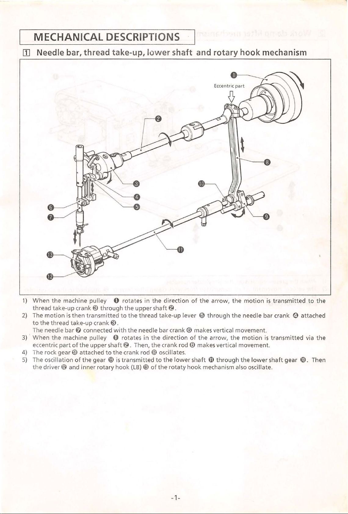
1)
When
thread
2)
The
to
The needle
3)
When
eccentric
4) The rock gea
5)
The oscillation
the
the
motion
the
thread
the
driv
take-up
part
er@
machine pulley 0 rotates in
crank@ through
is
then
transmitted
take-up
bar
machine pulley 0 rotates in
of
r@
of
and inner
crank@.
f)
connected
the
upper
attached
the
gear @
to
rotary
the
to
with
the
shaft@.
the
crank
is
transmitted
hook
upper
the
thread
needle bar
Then,
rod@
(LB) ® ofthe
the
direct
shaft@.
take-
the
direction
the
cra
osci
to
the
ion
up
lever
crank@
nk
rod@
llate
s.
lower
rotaty
of
the
arrow,
€)
throu
makes vertical movement.
of
the
arrow,
makes vertical movement.
shaft
ID
hook
mechanism also
the
gh
the
the
through
motion
needle bar crank e attached
motion
the
osc
lower
illate.
is
transmitted
is
tran
smitted via
shaft gear
®.
to
Then
the
the
-1-
Page 5
~
Work
clamp
lifter
mechanism
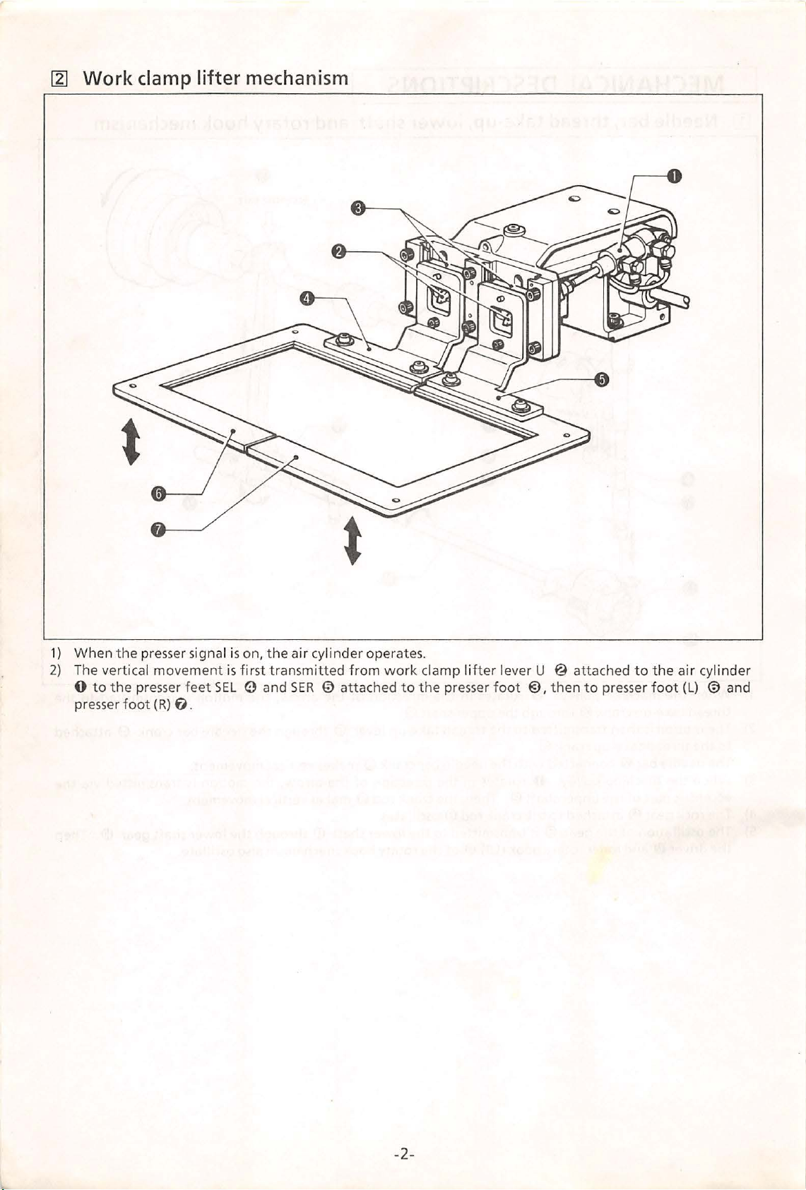
1)
When the
2)
The vertical
0
presser
to
the
foot
pre
sse
r signa l is on,
movement
presser
{R)
f).
the air
is fir
st transmitted
feet SEL 0 and
cylinder operates.
from
SER
0 attached
work
to
clamp
the
presser
lif
ter
lever U @ attached
foot @,then
to
presser
to
the
foot
air
{L)
cyl
inde
@ and
r
-2-
Page 6
@1
Feed
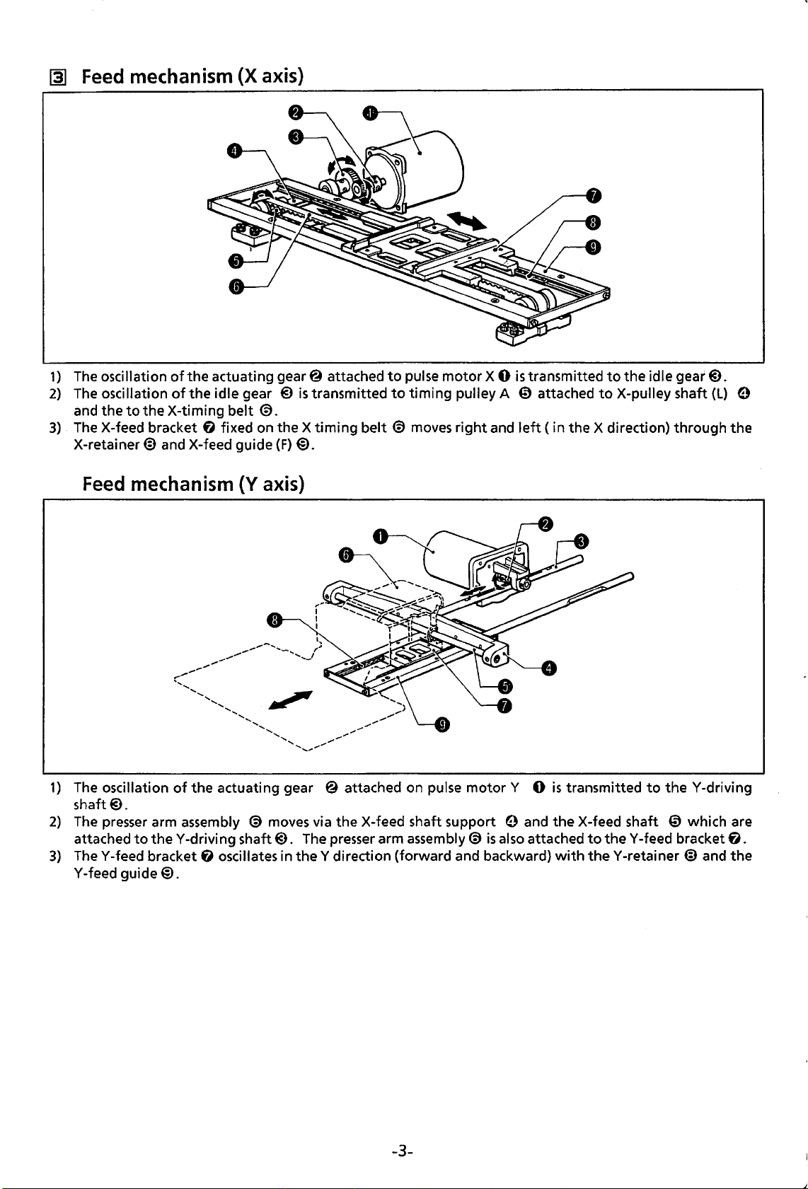
1)
The
2)
The
and
3)
. The X-feed bracket
X-retainer@ and X-feed guide
mechanism
oscillation
oscillation
the
to
the X-timing
of
the
actuating gear@ attached
of
the
idle gear @
fl
(X
axis)
is
belt
@.
fixed on the X
(F)
@.
transmitted
timing
belt
to
pulse
to
timing
@ moves
motor
pulley A
right
X 0
and
is
transmitted
€)
attached
left
(in
the X direction)
to
the
idle gear@).
to
X-pulley shaft
(L)
through
9
the
Feed
1)
The oscillation
shaft@.
2)
The
attached
3)
TheY-feed bracket
Y -feed
mechanism
presser arm assembly @ moves via the X-feed shaft support 9 and the X-feed shaft
to
guide@.
(Y
axis)
of
the actuating gear @ attached on pulse
theY-driving
shaft@).
f)
oscillates in
The
presser arm assembly@
theY
direction (forward and backward)
motor
is
also attached
Y 0
is
transmitted
to
theY-feed
with
theY-retainer@
to
the
Y-driving
€)
which are
bracket
and
fl.
the
-3-
Page 7
[A]
Intermittent presser mechanism
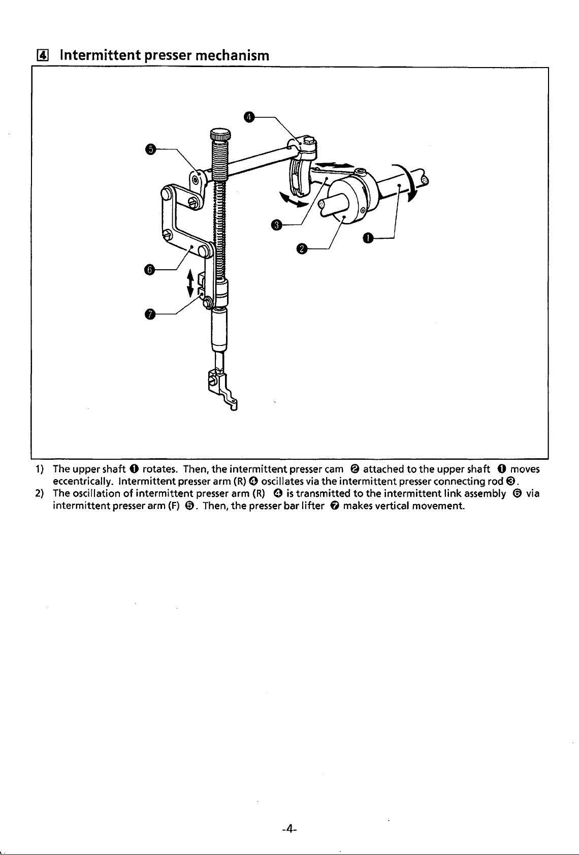
1)
The upper shaft 0 rotates. Then,
eccentrically.
2)
The
intermittent
oscillation
Intermittent
of
intermittent
presser arm
presser arm
presser arm
(F)
0.
Then,
the
intermittent
(R)
the
presser
0 oscillates via
(R) 0 is
presser bar
transmitted
lifter
cam
@ attached
the
intermittent
to
the
f1 makes vertical movement.
to
the
upper shaft 0 moves
presser connecting
intermittent
rod@.
link
assembly ® via
-4-
Page 8
~
Thread trimmer mechanism
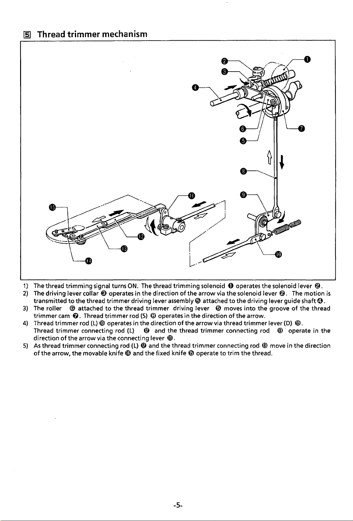
1)
The thread trimming signal turns
2)
The driving lever collar
transmitted
3)
The
roller @ attached
trimmer
4)
Thread trimmer rod (L) ® operates in the direction
Thread trimmer connecting rod (L) @ and
direction
5)
As
thread
of
the
to
the thread trimmer driving lever assembly@ attached
cam
fi.
of
the arrow via
trimmer
arrow, the movable knife
@)
operates in the direction
to
Thread trimmer rod
the
connecting rod
ON.
The
the thread trimmer driving lever
(S)
@ operates in
connecting lever
(L)
@ and the thread trimmer connecting rod @ move in the direction
G)
and the fixed
thread trimming solenoid 0 operates the solenoid lever
of
the arrow via the solenoid lever
to
the driving lever guide shaft
€)
moves
the
direction
of
the arrow via thread trimmer lever
the
thread trimmer connecting rod @ · operate in the
into
of
the arrow.
the
@.
groove
(D)
The
motion
of
the thread
@.
4D.
knife~
operate
to
trim
the thread.
@.
is
0.
-5-
Page 9
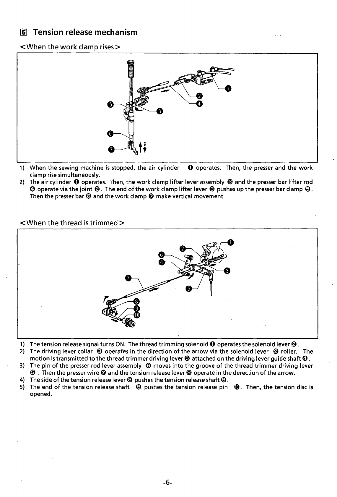
[§]
Tension
release
mechanism
<When
1)
When the sewing machine
clamp
2)
The
0 operate via
Then the
the
work
rise
simultaneously.
air cylinder 0 operates. Then, the
presser
clamp rises>
the
joint
bar
€)
@.
and
is
stopped, the air cylinder 0 operates. Then, the presser and the
work
The
the
end
work
of
the
clamp
clamp
work
f)
lifter
lever assembly
clamp
make vertical movement.
lifter
lever
@)
pushes
@)
and the
up
the
presser
presser
bar
bar clamp
work
lifter
rod
0.
<When
1)
The
2)
The
3)
The pin
the
thread
tension release signal turns
driving lever collar
motion
is
transmitted
of
the
presser
0 . Then the presser wire
4)
The
side
of
the tension release lever@
5)
The
end
of
the tension release shaft @
opened.
is
trimmed>
ON.
@)
operates in the direction
to
the
thread trimmer driving lever 0 attached on the driving lever guide shaft
rod lever assembly
f)
and the tension release lever@ operate in
The
thread trimming solenoid 0 operates the solenoid lever@.
of
the arrow via the solenoid lever @ roller.
€)
pushes
pushes
moves
the
into
the groove
tension release shaft@.
the tension release pin
of
the
the
thread trimmer driving lever
derection
tiD.
Then,
of
the arrow.
the
tension
The
e.
disc
is
-6-
Page 10
l1J
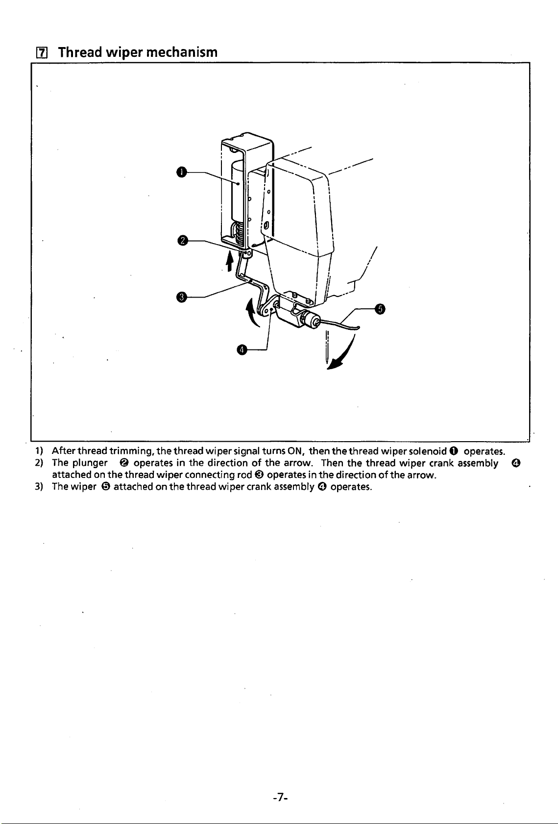
Thread
wiper
mechanism
1)
After
2)
The
attached on
3)
The
thread trimming,
plunger @ operates in the direction
the
thread
wiper 0 attached on the thread
the
thread
wiper
wiper
signal turns
connecting rod@ operates in
wiper
ON,
then
the
thread wiper solenoid 0 operates.
of
the
arrow. Then the thread
the
direction
crank assembly e operates.
wiper
of
the arrow.
crank assembly e
-7-
Page 11
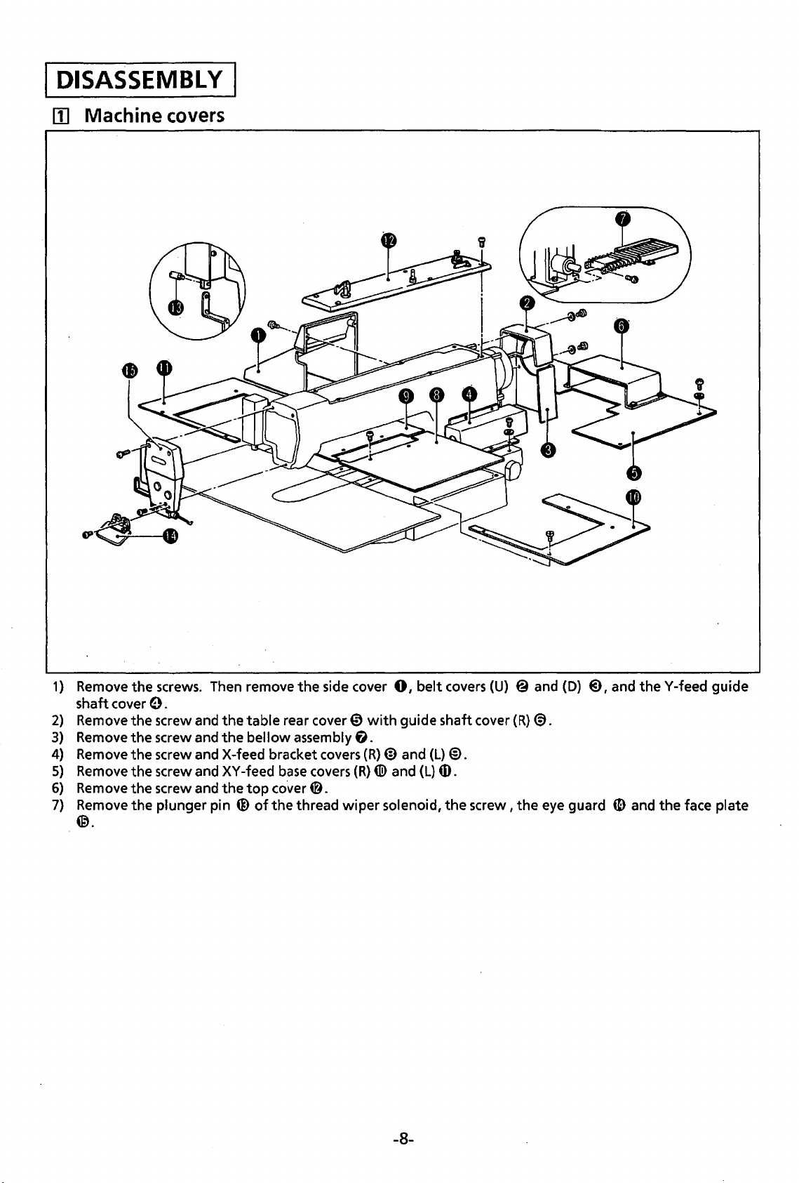
DISASSEMBLY
lii
Machine
covers
1)
Remove
shaft cover
2)
Remove
3)
Remove
4)
Remove
5)
Remove
6)
Remove
7)
Remove
@.
the
screws. Then remove
the
0.
the
screw and
the
screw and
the
screw and X-feed bracket covers
the
screw and
the
screw and
the
plunger pin
the
the
XY
the
@of
table
bellow
-feed
top
co.ver
the
rear cover@
assembly
base
thread
side cover
covers
0.
wiper
fl.
(R)
(R)
with
4li>
0,
belt
covers
guide shaft cover (R)@.
@)
and
(L)
and
(L)
ID.
solenoid,
the
(U)
@).
screw,
@ and
the
eye guard
(D)
@),
and
ID
the
Y -feed guide
and
the
face plate
-8-
Page 12
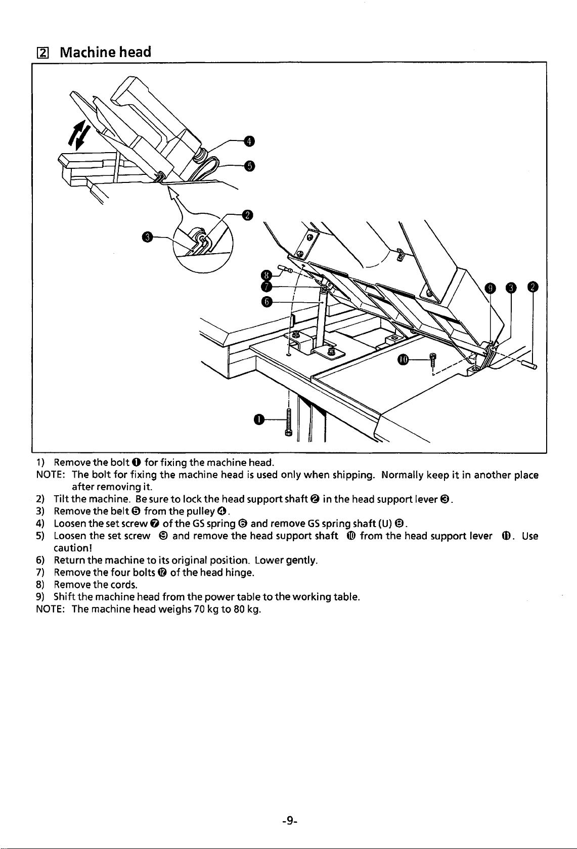
~
Machine head
1}
Remove
NOTE:
2)
Tilt
3}
Remove
4)
Loosen
5)
Loosen
caution!
6}
Return the machine
7)
Remove
8)
Remove
9)
Shift the machine head from the power table
NOTE:
the
bolt 0 for
The
bolt
for
fixing
after removing it.
the
machine.
the belt
the set screw
the set screw
the
the cords.
The
machine head weighs
four
Be
€)
from
bolts@
fixing the machine head.
the
machine head
sure
to
lock
the
the
pulley
9.
f)
of
the
GS
spring
@)
and remove the head support shaft
to
its original position. Lower gently.
of
the
head hinge.
70
kg
is
used
only when shipping. Normally keep
head support shaft@ in the head support lever@).
@)
to
80
and remove
to
the
kg.
GS
spring shaft (U}@.
((i)
working table.
from
the
head support lever (f).
it
in another place
Use
-9-
Page 13
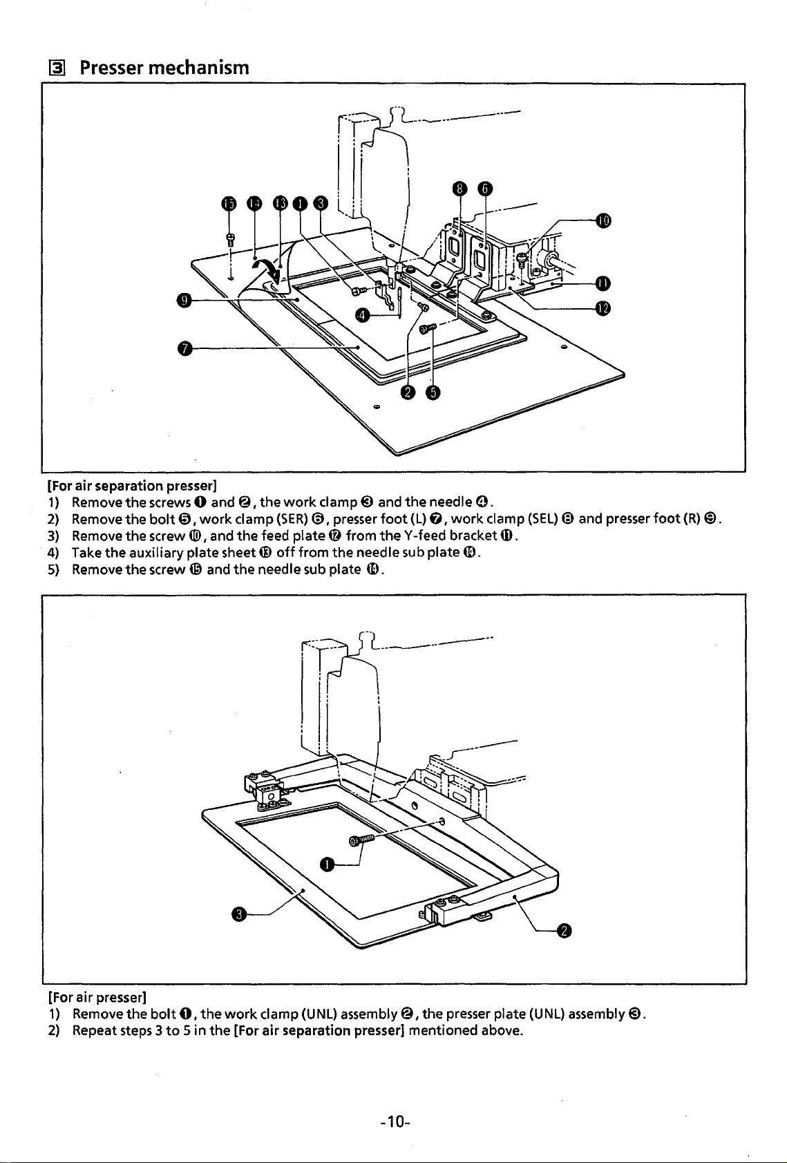
~
Presser
mechanism
[For
1)
2)
3)
4)
5)
air
separation presser]
Remove
Remove
Remove
Take
Remove
the
screws 0 and
the
bolt
the
screw«!>
the
auxiliary plate sheet@
the
screw@ and
€)
I
work
I and
@I
the
work
damp
{SER)@)
the
feed
plate@
off
from
the
needle sub plate
damp@
I presser
the
and
from
theY-feed
needle sub plate
4D.
foot
the
{L)
needle
tj
I
work
bracket
6).
0.
clamp
m.
{SEL)@
and presser
foot
{R)@).
[For
air
presser]
1)
Remove
2)
Repeat steps 3
the
bolt
to 5 in
01
the
the
work
[For
damp
{UNL) assembly
air
separation presser] mentioned above.
@I
the
presser plate
-10-
{UNL)
assembly@.
Page 14
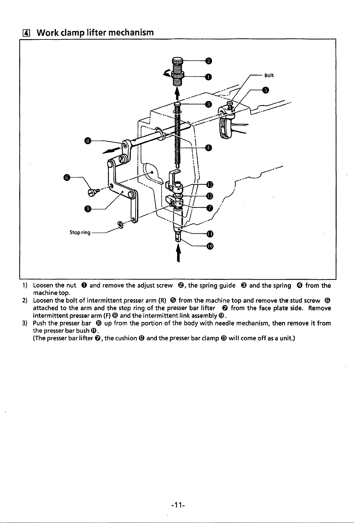
[j] Work
clamp
lifter
mechanism
1)
Loosen
machine top.
2)
Loosen
attached
intermittent
3)
Push
the
(The
the
nut
the
bolt
to
the
the
presser bar
presser
bar
presser bar
Stop
ring~
0 and remove
of
intermittent
arm and
presser arm (F)@ and the
tiD
bush
ID.
lifter
f),
....
-
the
adjust screw
presser arm
the
stop ring
up from the portion
the
cushion @
(R)
@ from the machine
of
the presser bar
intermittent
of
the
and
the
presser
@,the
link assembly@.
spring guide
lifter
body
with
bar clamp@
needle mechanism, then remove
@)
and the spring 0 from
top
and remove the stud screw @
f)
from the face plate side.
will
come
off
as
a unit.)
the
Remove
it
from
-11-
Page 15
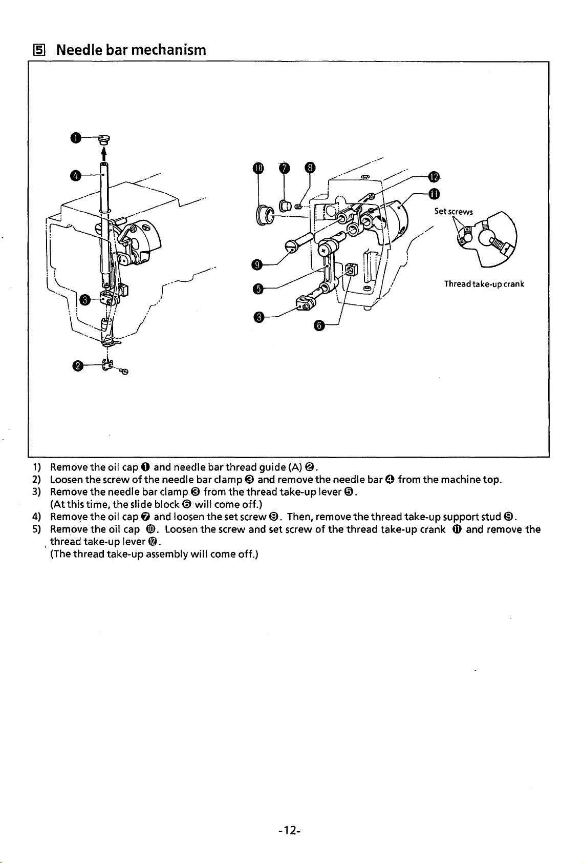
~
Needle bar
mechanism
Thread
take-up
crank
1} Remove the oil cap 0 and needle bar thread guide
2}
Loosen
3}
Remove
(At
4}
Remove
5}
Re~ove
, thread take-up lever
(The thread take-up assembly
the
screw
the
this time,
the
the oil cap
of
the needle bar clamp@ and remove
needle bar clamp@
the
slide block@)
oil
cap
6 and loosen
([!).
Loosen
0.
will
from
the
thread take-up lever
will
come off.}
the
set screw@. Then, remove
the
screw and set screw
come off.}
(A}@.
the
of
needle
bare
from
0.
the
thread take-up support stud@).
the
thread take-up crank
the
machine top.
6)
and remove
the
-12-
Page 16
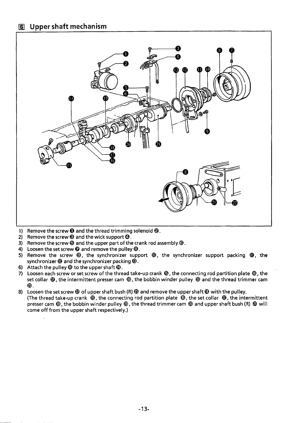
III
Up_per
shaft mechanism
1}
Remove
2)
Remove
3)
Remove
4)
Loosen
5)
Remove
synchronizer@ and
6)
Attach the pulley@
7)
Loosen
set collar
the screw 0 and the thread trimming solenoid@.
the
screw@)
the screw 0 and the upper part
the set screw G and remove the pulley@.
the screw
each
screw or set screw
0
the
1
w.
8)
Loosen
(The thread take-up crank
presser
come
the set screw 0
cam
4ID,
the bobbin winder pulley
off
from the upper shaft respectively.)
and the wick support
@)
the
1
the
to
the
intermittent
of
synchronizer support ® 1 the synchronizer support packing
synchronizer packing@.
upper shaft
of
the thread take-up crank
presser
upper shaft
@,the
0.
of
the crank rod assembly@.
ID.
@,the
cam
4ID
I
the
bobbin
bush
(R)
fD
and remove the upper shaft
connecting rod partition plate (@,the
@I
the
thread trimmer
winder
connecting rod partition plate
pulley @
cam
W and upper shaft
and
the thread trimmer
ID
with
the
set
collar 0 I
pulley.
the
intermittent
bush
(R)
tD
the
1
(@ 1 the
cam
fD
will
-13-
Page 17
[1]
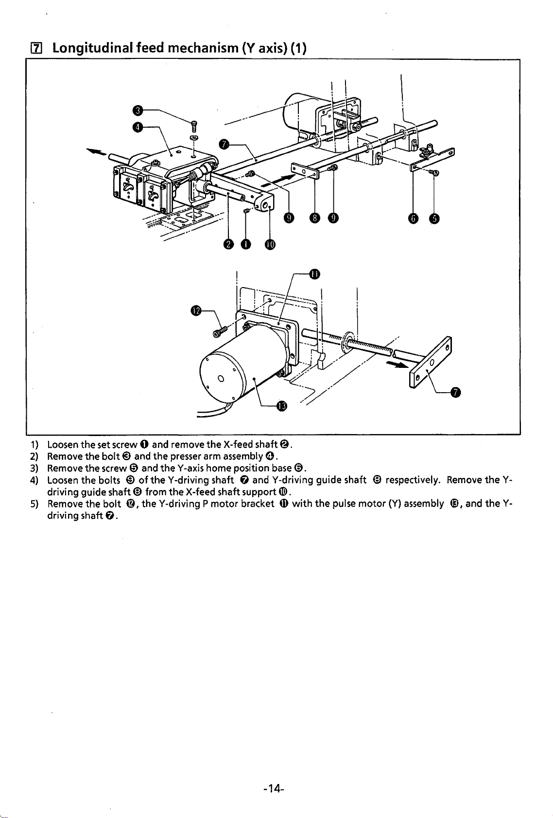
Longitudinal feed mechanism (Y axis) (1)
1}
Loosen
2}
Remove
3}
Remove the screw 0 and
4}
Loosen
drivi ng guide shaft
5}
Remove
driving shaft fJ.
the set screw 0 and remove
the bolt@) and
the bolts
the
bolt
the
X-feed shaft@.
the
presser arm assembly
theY
-axis home position
@)
of
theY-driving
ED
from the X-feed shaft support
0,
theY-driving P motor
shaft
0.
base
@.
f)
andY-driving guide shaft
tiD.
bracket
ID
with
the
pulse
ED
motor
respectively.
(Y}
assembly
Remove
®,and
theYtheY-
-14-
Page 18
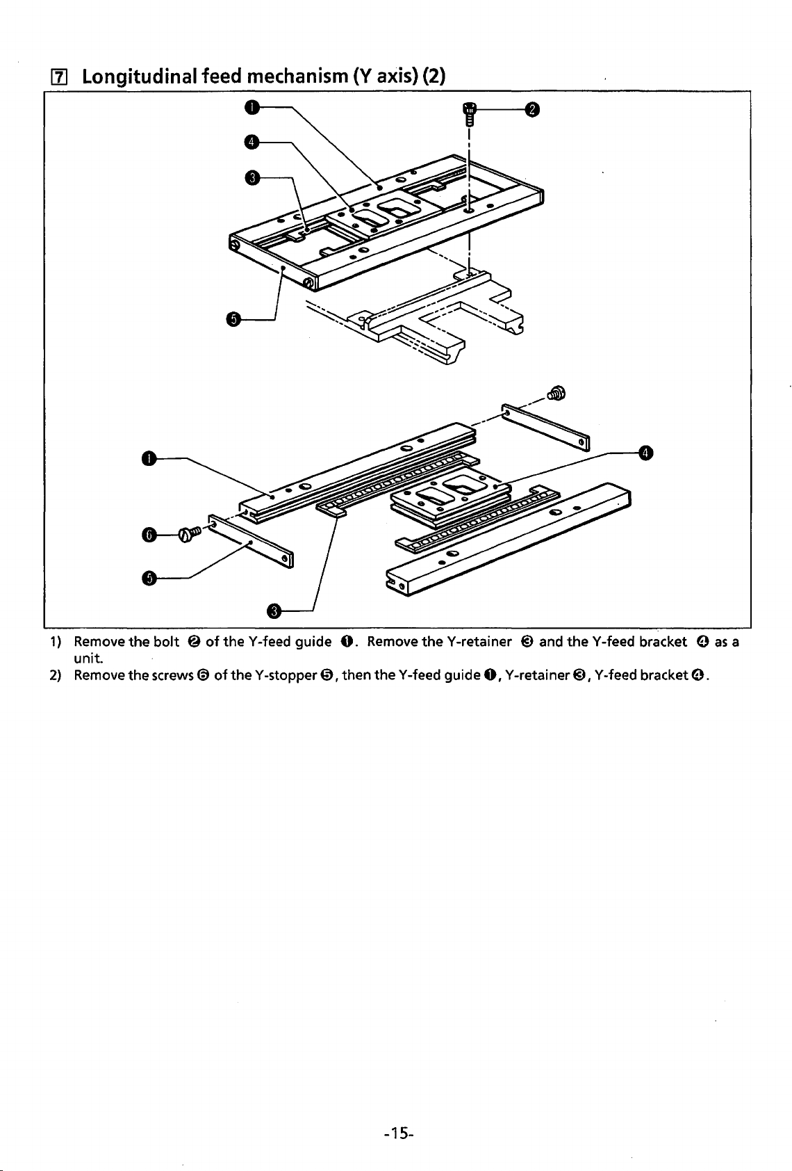
11]
Longitudinal feed
mechanism
{Y
axis)
{2)
' .
I
I
1)
2)
Remove
unit.
Remove
the
bolt @ of
the screws@
theY-feed
of
theY-stopper
guide
0,
0.
Remove
then theY-feed guide
theY-retainer
@)
and
theY-feed
0,
Y-retainer@), Y-feed bracket
bracket 9
9.
as
a
-15-
Page 19
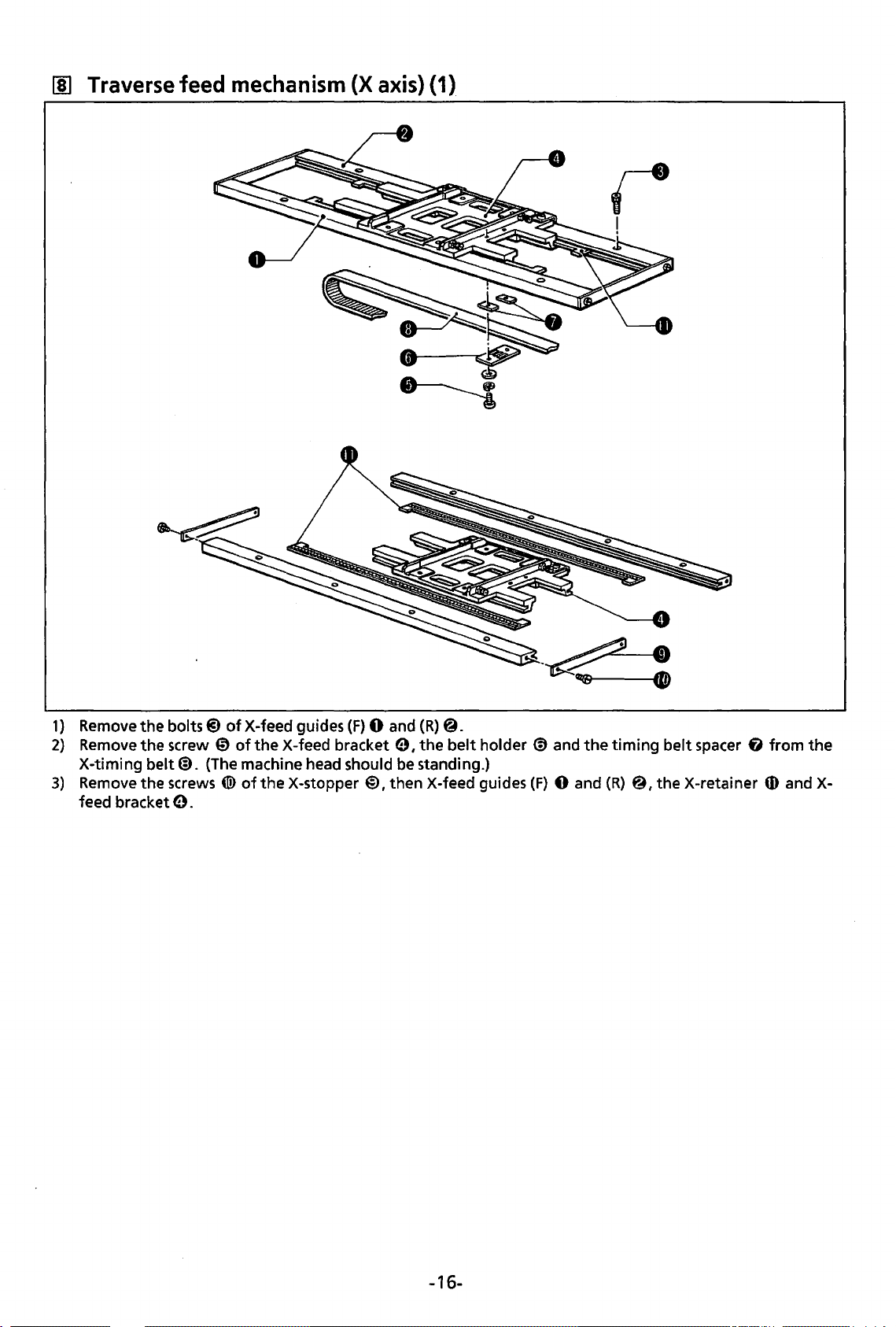
00
Traverse
feed
mechanism
(X
axis)
(1)
r
!
1)
Remove
2}
Remove
X-timing
3}
Remove the screws ®
feed bracket e.
the
bolts@)
the
screw 0
belt@). (The machine head should be standing.}
of
X-feed guides
of
the
X-feed bracket e I
of
the
X-stopper
(F)
0 and
@,then
(R)
@.
the
belt
holder @ and
X-feed guides
(F)
the
0 and
timing
(R}
@
1
belt
the
spacer
X-retainer
fJ
from
ID
and X-
the
-16-
Page 20
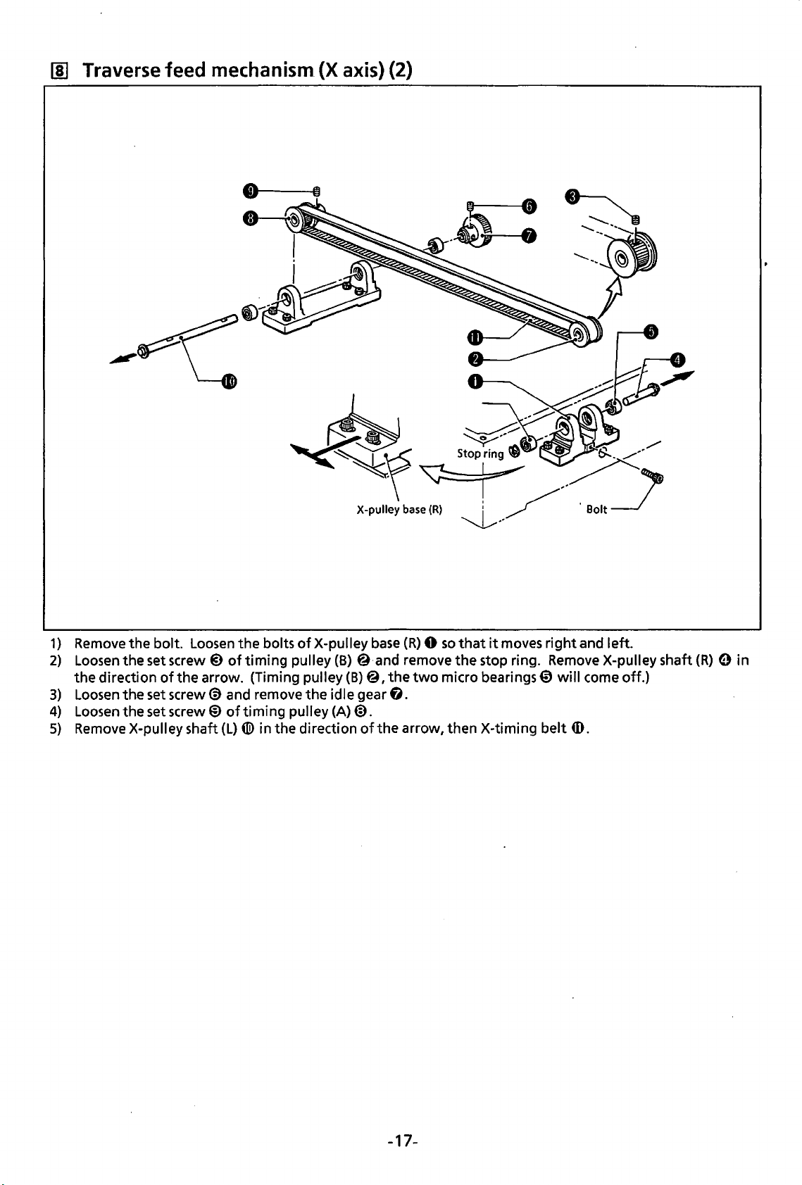
II)
Traverse
feed
mechanism
(X
axis)
(2)
1}
2}
3)
4)
5)
Remove
Loosen
the
direction
Loosen
Loosen
Remove
the bolt.
the setscrew@)
the set
the set
X-pulley shaft
Loosen
of
the arrow. (Timing pulley (B)@, the
screw@)
screw®
X-pulley
the bolts
oftiming
and remove the idle gear
of
timing
(L)
® in the direction
of
X-pulley
pulley(B} @·and remove
pulley (A)@.
of
base
(R)
base
(R} 0 so
two
that
it
the
stop ring. RemoveX-pulleyshaft(R} 0 in
micro bearings 0
6.
the
arrow, then X-timing belt
moves
right
will
and left.
come off.)
ID.
-17-
Page 21
~
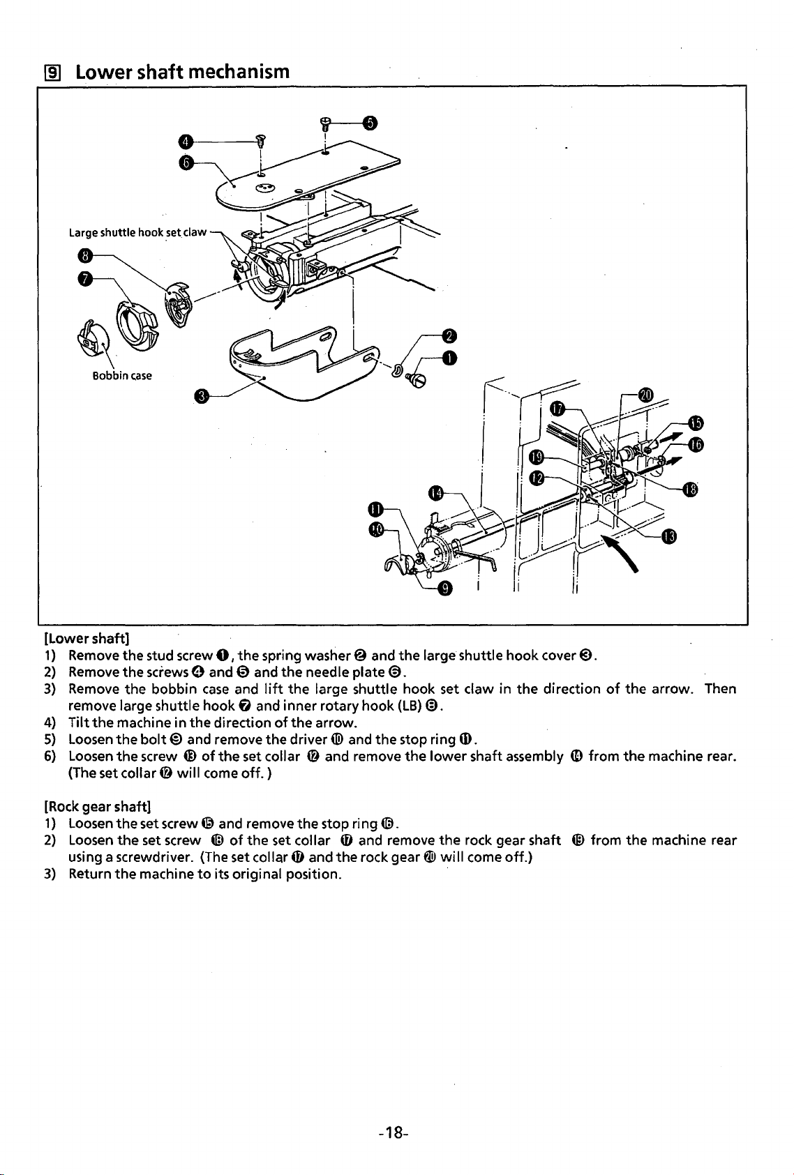
Lower shaft
mechanism
Large shuttle hook
.set.
claw
[Lower shaft]
1)
Remove
2)
Remove
3)
Remove
remove
4) Tilt
5)
Loosen
6)
Loosen
(The set
[Rock
1)
Loosen
2)
Loosen
using a screwdriver.
3)
Return
the stud screw
the
the bobbin
large shuttle hook
the
machine in the direction
the
the
collar@
gear shaft]
the set screw @ and remove the stop ring
the
the
screws
bolt@
screw @
set screw
machine
and remove the driver«!> and the stop ring (I).
will
0,
the
spring wastier@ and
the
9 and 0 and the needle plate@.
case
and
lift
the large shuttle hook set claw in the direction
f)
and inner rotary hook (LB)@.
of
the
arrow.
of
the
set collar @ and remove
come
off.)
@.
tiD
of
the
set collar 0 and remove the rock gear shaft ® from the machine rear
(The
set collar 0 and the rock gear W
to
its original position.
large shuttle hook cover@.
the
lower shaft assembly
will
come off.)
(D
of
the arrow. Then
from
the
machine rear.
-18-
Page 22
1m!
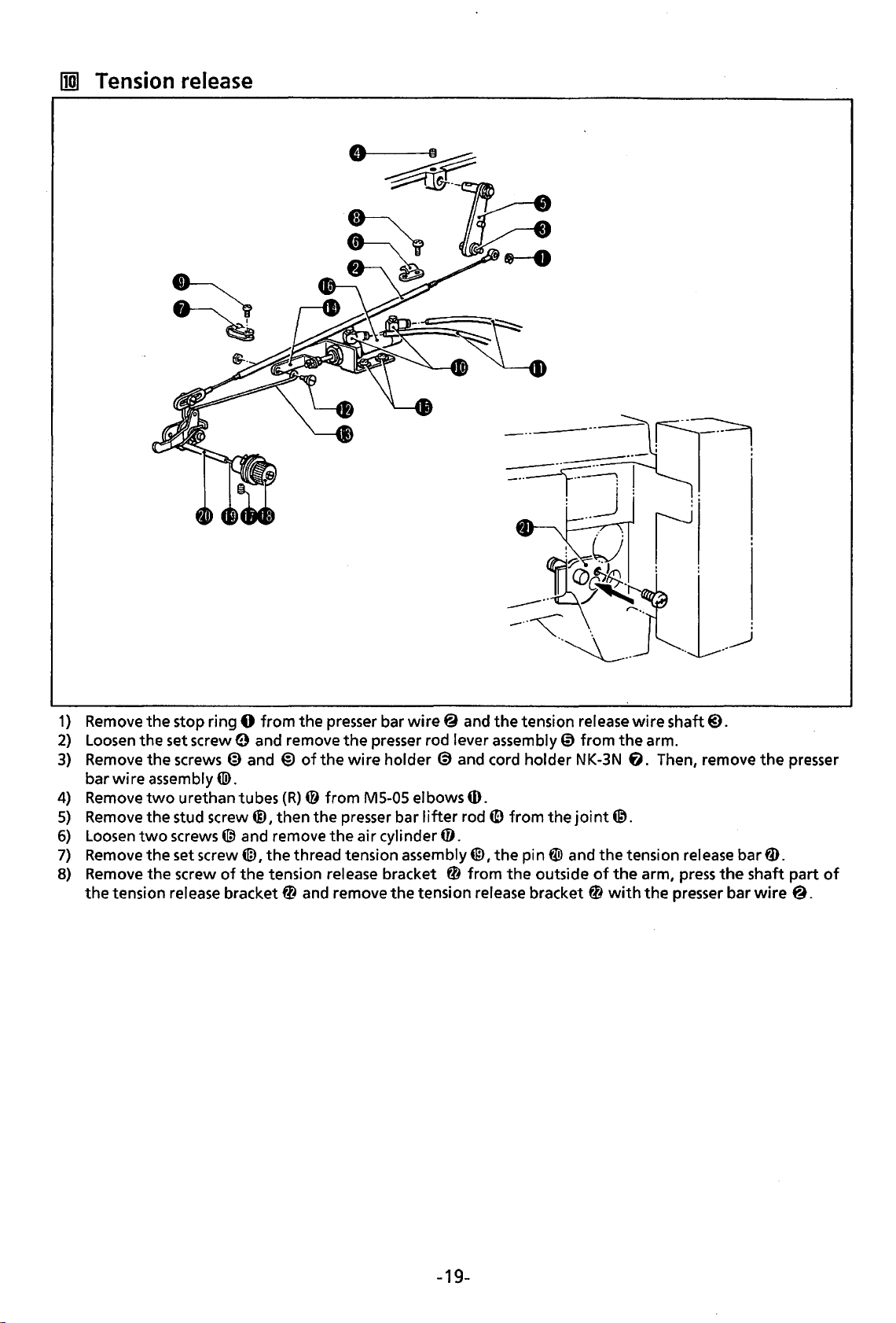
Tension release
--~r=:r-~
~~~~--:
I J
. .
II
1)
2}
3}
4}
5)
6)
7}
8}
Remove
Loosen
Remove
bar
Remove
Remove
Loosen
Remove
Remove
the
the
stop ring 0
the
set screw e and remove
the
screws @ and @
wire
assembly«!>.
two
urethan tubes (R)@
the
stud screw@,
two
screws@ and remove
the
set screw@,
the
screw
tension release bracket@ and remove
of
from
the
of
the
then
the
the
thread tension assembly@,
the
tension release bracket 0
presser bar
the
wire
from
presser bar
the
air cylinder
wire@
presser rod lever assembly 0
holder ® and cord holder NK-3N
M5-05 elbows ill.
lifter
and
rod
0.
from
the
tension release bracket 0
-·~.
the
tension rei
ID
from
the
the
pin
@>
the
outside
·-~..
ease
wire
from
the
arm.
fi.
joint@.
and
the
tension rei
of
the
arm,
with
the
..
__
_.)
shaft@).
Then, remove
ease
bar
press
the
presser bar
:
the
fD.
shaft
wire@.
presser
part
of
-19-
Page 23
Ill]
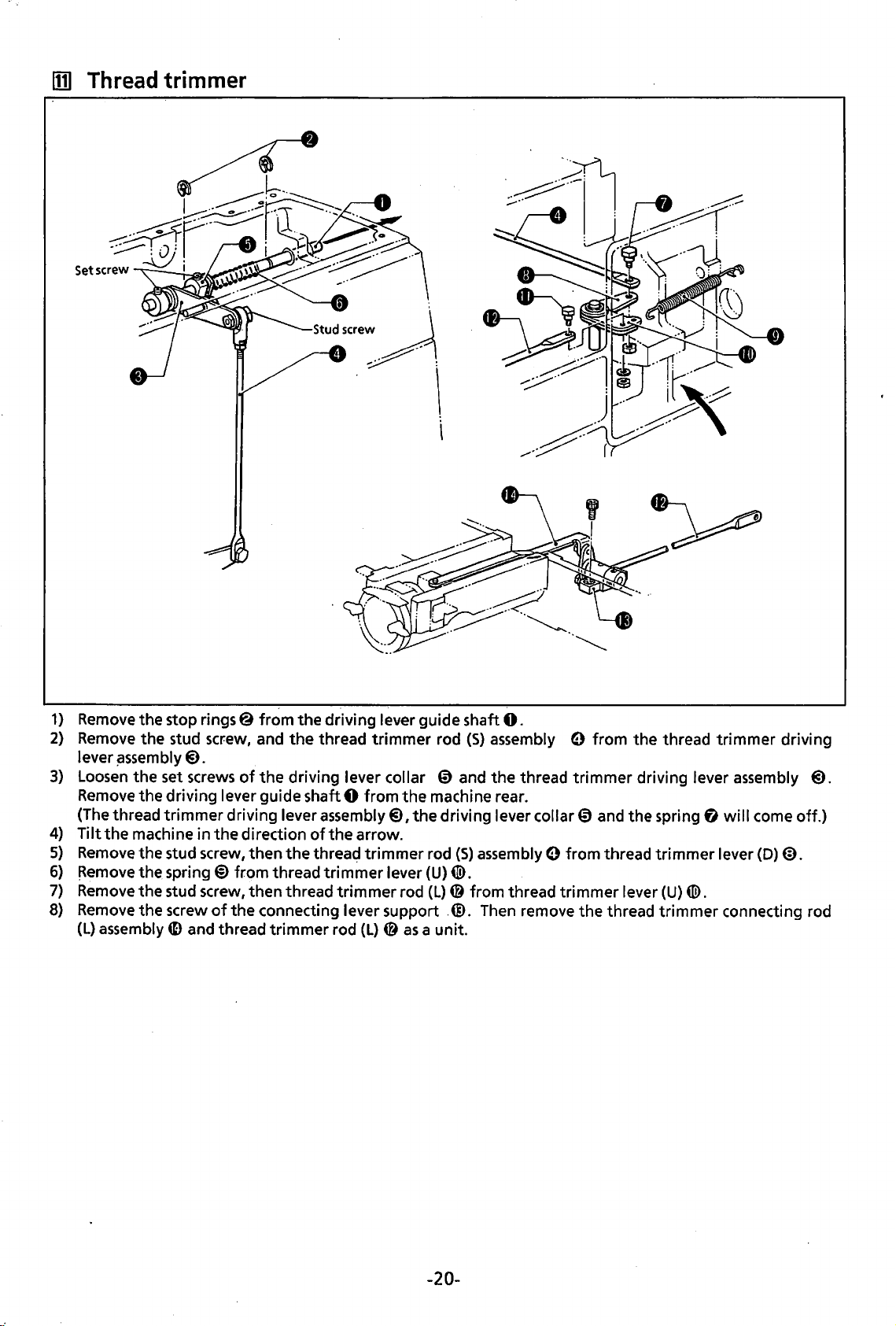
Thread trimmer
1}
Remove
2)
Remove
lever
3)
Loosen
Remove
(The thread trimmer driving lever
4)
Tilt
5)
Remove
6)
~emove
7)
Remove
8)
Remove
(L)
the stop rings@ from the driving lever guide shaft
the stud screw, and
~ssembly@).
the set
the driving lever guide shaft 0 from
the
machine in
the stud screw, then
the spring@ from thread
the stud screw, then thread
the screw
assembly
screws
ID
and thread trimmer rod
of
the
direction
of
the connecting lever support
0.
the
thread trimmer rod
the
driving lever collar 0 and the thread trimmer driving lever assembly
the
assembly@),
of
the arrow.
the
threac;j
trimmer
trimmer
trimmer
(L} @ as
the
lever (U)@.
rod (L)@ from thread trimmer lever
(S}
assembly 0 from the thread trimmer driving
machine rear.
driving lever collar 0 and the spring
rod
(S}
assembly 0 from thread
.@.
Then remove the thread
a unit.
fl
trimmer
(U)
tiD.
trimmer
will
lever
connecting rod
@).
come off.}
(D)@).
-20-
Page 24
ASSEMBLY
[1]
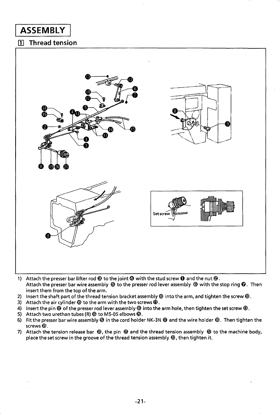
Thread tension
-··-
~__:_--,!
---~
Setser~
---~--~
.:-----::::::··- ' :
' _j
·-~--
.
1··
.
,.
..
__
_)
l'l~l»>
I
.
1) Attach
Attach
insert
2)
Insert
3)
Attach
4) Insert
5)
Attach
6)
Fit
screws@.
7) Attach
place
the
the
presser bar lifter rod@)
the
presser
them
from
the
shaft
the
air cylinder«!)
the
pin@
two
urethan
presser
the
tension release
the
set
bar
the
top
part
of
of
the
tubes
bar
wire assembly 0 in
screw
in
the
to
the
joint
0 with
wire assembly 0
of
the
arm.
the
thread
to
presser rod lever assembly@) into
(R)
bar
groove
tension bracket assembly@ into
the
arm
([;}to M5-05
@!>,the
of
with
the
the
pin
thread
to
the
the
two
elbows@.
cord holder
ID
and
tension assembly
the
presser rod lever assembly
screws
NK-3N
the
stud screw 0
ID.
the
arm hole,
0 and
thread
tension assembly 0
0,
the
then
-21-.
and
€)
arm, and
then
the
wire holder
tighten
the
nut@.
with
tighten
tighten
it.
the
the
tiD.
to
stop ring
the
screw@).
set
screw®.
Then
tighten
the
machine body,
fl.
Then
the
Page 25
lZJ
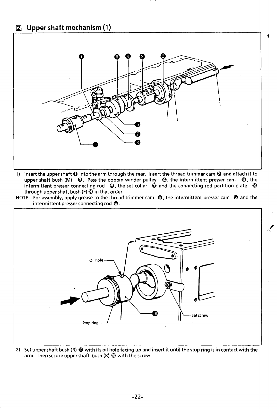
Upper shaft mechanism (1)
1)
Insert the upper shaft 0
upper shaft
intermittent
through upper shaft
NOTE:
For
intermittent
bush
presser connecting rod
assembly, apply grease
(M)
bush
presser
into
the arm through the rear. Insert the thread trimmer
@).
Pass
the bobbin
(F)@)
in
that
to
the
connecting rod
@,the
order. ·
thread
@.
winder
set collar
trimmer
pulley
fj
cam
0,
the
and the connecting rod partition plate @
@,the
intermittent
intermittent
presser
cam @ and
presser
cam
cam
attach
0,
it
the
to
0 and the
,
...
2)
Set
upper shaft
arm. Then secure upper shaft
bush
(R)
{{!)
with
its oil hole facing up
bush
(R)
{{!)with
the
and
screw.
insert
it
until the stop ring
-22-
is
in contact
with
the
Page 26
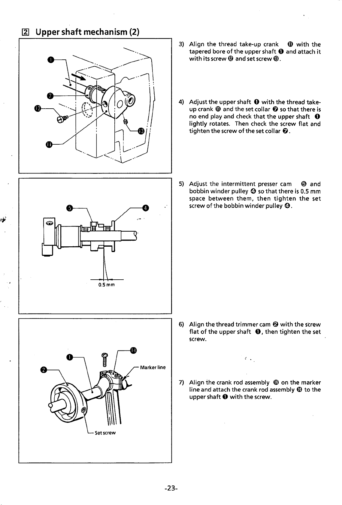
~
Upper shaft
mechanism
(2)
3)
Align
the
thread
tapered
with its screw@ and
4)
Adjust
up crank
no end play
lightly rotates. Then check
tighten
5)
Adjust
bobbin winder pulley 0 so
space
screw
bore
the
upper shaft 0 with
Q)
the
screw
the
intermittent presser cam 0
between
of
the
take-up crank
of
the
and
the
and
check
of
them,
bobbin winder pulley
Q)
with
the
upper shaft 0 and attach it
set
screw@.
the
set collar 6 so
that
the
upper shaft 0
the
screw flat and
the
set
collar
6.
that
there
then
tighten
thread
that
there
is
0.5
the
take-
is
and
mm
set
0.
O.Smm
Marker line
6)
Align
thethread
flat
of
the
screw.
7)
Align
the
crank rod assembly
line
and
attach
upper shaft 0 with
trimmer cam @ with
upper shaft
the
0,
crank rod assembly
the
screw.
then
CD
the
tighten
on
the
CD
screw
the
set
marker
to
the
-23-
Page 27
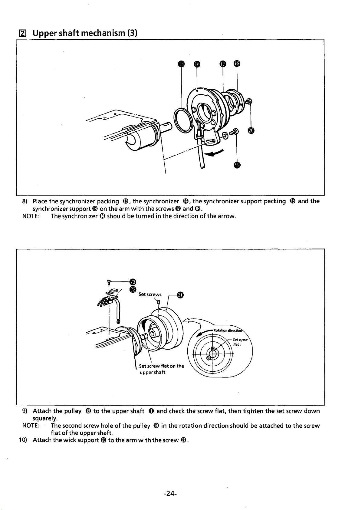
~
Upper shaft
8)
Place
synchronizer
NOTE:
mechanism
the synchronizer packing
support®
The
synchronizer
on
ID
the
should
(3)
@,the
arm
synchronizer
with
the
screws
be
turned in the direction
ID,
the synchronizer support packing @ and the
0 and
@.
of
the arrow.
9)
Attach the pulley @
squarely.
NOTE:
1
0)
The
second
flat
of
Attach the wick support
the upper shaft.
to
the
screw hole
fll)
to
upper shaft 0 and check the screw flat, then tighten the set screw down
of
the
pulley @ in
the arm
with
the
the screw
rotation direction should
tD.
-24-
be
attached
to
the screw
Page 28
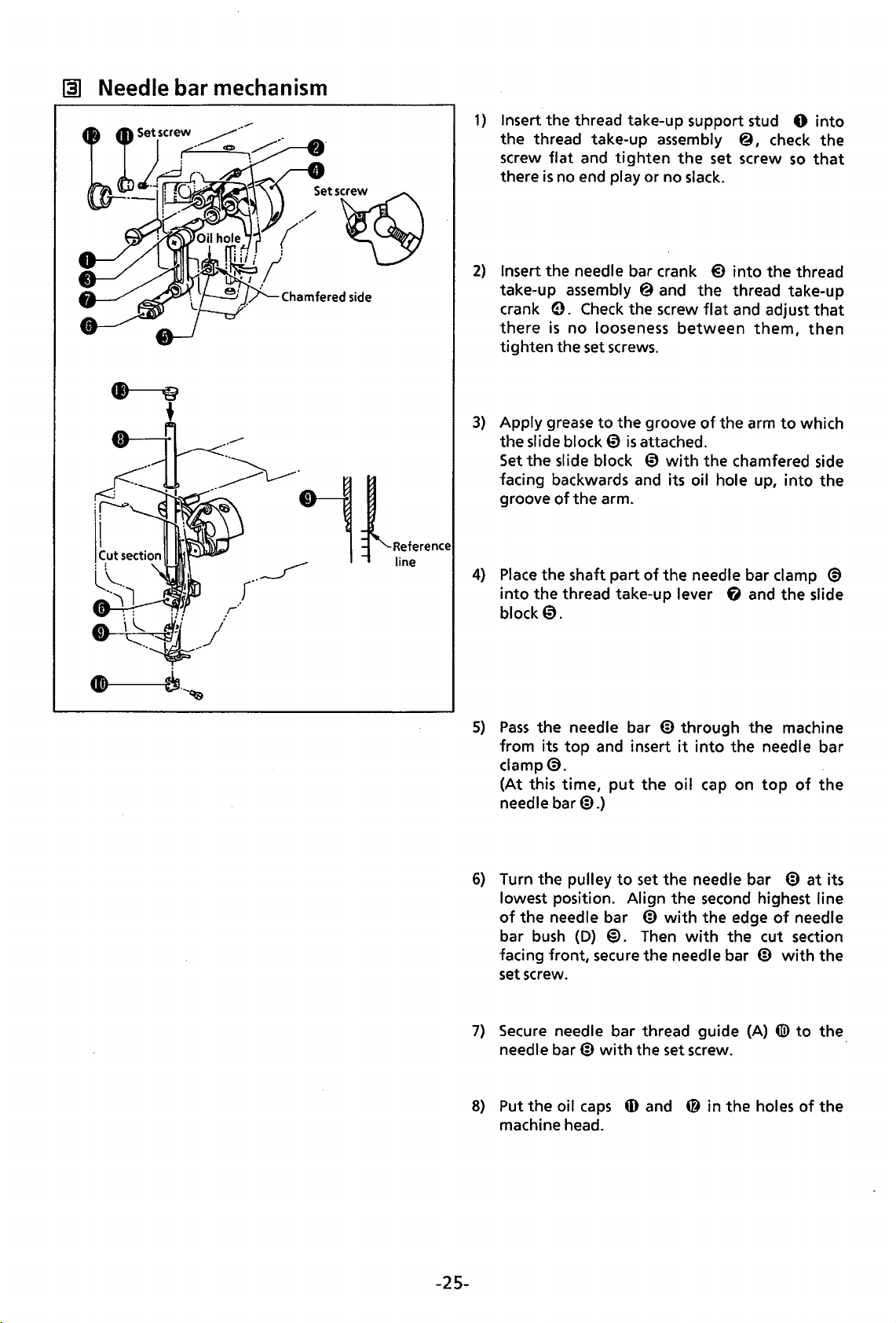
@1
Needle
bar
mechanism
1)
Insert
the
thread
the
thread
screw flat
there
is
2)
Insert
take-up
crank
there
tighten
3)
Apply grease
the
slide block 0
Set
the
facing backwards and its
groove
take-up
and
tighten
no
end
play
the
needle
assembly @
e.
Check
is
no
looseness
the
set
screws.
to
the
slide block 0
of
the
arm.
take-up
bar
the
is
attached.
support
assembly
the
or
no slack.
crank @ into
and
screw flat
between
groove
with
oil hole up, into
stud 0 into
@,
set
screw so
the
thread
and
them,
of
the
arm
the
chamfered side
check
the
thread
take-up
adjust
to
which
the
that
that
then
the
4}
Place
the
shaft
into
the
thread
block
0.
5}
Pass
the
needle
the
the
needle
bush
screw.
top
time,
bar@.}
pulley
(D)
needle
bar@
from its
clamp@.
(At this
needle
6)
Turn
lowest position.
of
bar
facing front, secure
set
7)
Secure
needle
part
of
take-up
bar @
and
insert it into
put
the
to
set
Align
bar
@
@.
Then
the
bar
thread
with
the
the
needle
lever
through
oil
the
needle
the
with
with
needle
set
screw.
guide
bar
f)
and
the
the
cap
on
bar @ at
second highest line
the
edge
the
bar
@ with
(A}
clamp
the
machine
needle
top
of
of
needle
cut
section
(I!)
to
@)
slide
bar
the
its
the
the
8)
Put
the
oil caps
machine head.
-25-
ID
and @ in
the
holes
of
the
Page 29

[A]
Work
clamp
lifter
mechanism
(1)
1)
Insert
the
presser
presser bar clamp 0
2)
Secure
3)
Insert
NOTE:
4) Pass
presser arm
5)
Attach
with
the
the
spring®
Adjust
top,
then
intermittent
the
the
stop ring.
bar@
through
presser
the
(R)@.
intermittent
bar
and
nut
@ so
secure it.
presser arm
into
the
presser
the
presser
clamp 0 with
the
spring guide 6 into
that
there
is
(F) ® through
link assembly
bar
bar@
the
screw.
25
mm distance
@to
bush
0.
in
the
spreader
the
arm with
Pass
that
order.
arm from
between
the
presser bar lifter @),the cushion 0 and
the
top
and attach
the
adjust screw @
shaft bushes (L) and
the
stud screw, and
(R)
to
the
screw@.
top
and
ID,
then
the
presser bar lifter
the
the
machine
insert it into
@)
-26-
Page 30

[!]
Work
clamp lifter mechanism (2)
6)
Turn the pulley
lowest position. Position
arm
(F)(@
flush when
Then tighten the
to
and the
intermittent
set
the needle bar @ at its
intermittent
arm
so
that
their indexes are
rise
is
at its maximum.
bolt
of
presser
arm (R)@.
presser
NOTE:
7)
8)
Check
to
arm
(F) ® has
Attach the
so
that
aligns
Attach the needle@
the
with
work
the
be
top
sure
clamp
edge
top
that
Intermittent
no end play.
(D
to
the presser
of
the
end
of
the screw.
to
the needle bar
work
presser
bar@
clamp (D
@.
+
9)
Turn the pulley
that
the needle @
work
1
0)
Turn the pulley
lowest position.
bar
aligns
the screw
to
turn
the
presser
comes
clamp
(D
hole.
to
set the
Vertically adjust
@
so
that
part A
with
the needle plate top, then tighten
of
the
presser
in the center
presser
of
the
work
bar clamp
bar @
of
bar @
the
presser
clamp (D
0.
at
so
the
its
-27-
Page 31

~
Thread trimmer {1)
1)
Put the thread trimmer driving lever assembly
0 between the thread trimmer
bush
(M)
upper shaft
2)
Attach the thread trimmer rod
to
the
thread trimmer driving lever assembly
Secure
3)
Pass
the
shaft
it
@ and
assembly 0 in
them
with
the driving lever guide shaft 0 through
bush
8 x
15
0
into
the arm from the outside and
through the spring
the
thread
@).
the stud screw and the nut.
®,insert
f),
trimmer
that
order.
the driving lever guide
the driving lever collar
cam
(S)
assembly 0
driving
@ and
0.
pass
lever
4)
Attach the stop rings
shaft
0 and contact the driving lever collar
and the stop ring, then tighten them.
Similarly, attach
lever assembly 0
5)
Put
the
pin part
@)
into
the groove
then
attach
assembly
(li)
the
to
the arm
to
the driving lever guide
the
thread
to
the
stop ring and
of
the solenoid lever assembly
of
the driving lever collar
thread
trimming
with
trimmer
the
two
driving
secure
solenoid
screws.
@)
it.
@,
-28-
Page 32

~
Thread trimmer (2)
.Bolt
t--Setscrew
!
6)
Attach
assembled thread
thread trimmer connecting rod
arm
7)
Attach the thread trimmer connecting rod
to
rod
assembly@
8)
Attach the thread trimmer rod
to
screw(@
Attach thread trimmer rod (L)
trimmer lever
the
the
connecting
trimmer
with
the bolt.
the pin part
(L)
thread trimmer lever
and the
nut
ti9
of
@ and
to
the arm
nut
(U) 0 with
and
the
thread trimmer connecting
attach
i).
washer
lever
support
rod
(L)
the
needle
with
the
screws.
(S)
(D)
@
the stud screw
tD.
(L)
with
ID
@)
ID
and
0
to
the
4D
plate
assembly 0
the stud
to
thread
@,
9)
Hook the spring
thread trimmer lever
10)
Adjust the adjust screw ~ so
the thread trimmer driving lever assembly 0
smoothly
thread trimmer
with
NOTE:
11)
This
large curved
cam
Vertically adjust thread
and
movable knife
plate assembly
lever
goes
the
nut
adjustment should
groove.
(U)
0 and align
(U) 0 with
@to
spring hook
{U)
0.
that
in and
cam
out
the groove
@.
Then
secure them
fD.
be
performed in the
part
of
the
thread
~arge
trimmer
the
V notch ®
with
the index on
@,then
the
nut
secure
(ID.
curved part
levers
thread trimmer
(S)
@)
and
the roller
of
trimmer
(D)
of
the
needle
of
the
@
the
-29-
Page 33

.~~-
"J·:
~;
..
?'
··
·
[§]
Presser mechanism
[For
air
separate presser]
1)
Attach
2)
Put
plateO.
NOTE:
3)
Attach
4)
Attach
assembly®
the
needle sub
the
auxiliary sheet @ on
The sheet should be replaced
the
feed plate 0
work
clamp
with
(SER)
the
bolts.
plate 0 to
the
to
theY-feed
fj
I presser
the
needle sub plate supports
needle sub plate 0
with a new
bracket 0
foot
one every
(L)@ I
with
work
clamp (SEL)@ I presser
top
with
month.
the
screws.
(L)
and (R)@
aligning
with
the
its rear end
foot
(R)
screws.
with
4ID
to
the
the
work
needle sub
clamp
-30-
Page 34

[1]
Feed
1.5 mm
mechanism
(X
axis)
(1)
1)
Place
the
pass
X-pulley shaft
the
screw
NOTE:
2)
NOTE:
Put
Place
the
through
the
X-pulse motor.
Check the screw
·
the
shaft, then secure the idle
Provide a
(A)
X-timing
flat
timing
X-timing belt @ and
the
f)
with
belt@
(R)
9 through
on X-pulley shaft
pulley
micro bearing 8
1.5
(B)@)
flat
on X-pulley shaft
mm gap between
two
set screws.
and
in
timing
the
(R)
e and secure
the
center
timing
@,and
gear®
timing
pulley
attach them
(B)
@ on X-pulley
micro bearing 8
timing
of
X-pulley
pulley (A)
(L)
@ and adjust X-pulley shaft
and
timing
pulley (A)
pulley (A)
€),
pulley (B)@
base
(R)
f)
on X-pulley
to
the
idle gear
f)
and X-pulley
and attach
0 and secure
f)
base
with
(R)
0.
the
with
base
(L)
tiD
by pressing
(L) @ so
the set
base
To
attach
stop ring
the
set screw.
it
with
@.
Pass
that
screws.
(L)
@ and secure
timing
to
the
two
X-pulley shaft
the
there
pulley
the shaft.
set screws.
driving gear m on
is
no end play in
timing
(B)
@,
Check
(L)
@
pulley
·
-31-
Page 35

[11
Feed
mechanism
(X
axis)
(2)
3)
After
Using caution
guides
NOTE:
Wire
applying grease
that
no steel balls (5/32") @ drop
(F)
G)
and
(R)
®.
together
the retainer and
to
the
X-retainer
@I
place steel balls (5/32") @ on
out
the
feed guide. Attaching
of
the
X-retainers
to
the bed
the
X-retainer @ respectively.
@I
assemble them
will
be easier.
to
X-feed
4)
Place
the back side
feed guide (R)@
5)
Put
the
X-feed bracket 0 between X-feed guides
bed
with
the
6)
Attach
7)
Attach the X-stoppers
NOTE:
the
At
this time,
bolt®
bolt
of
X-feed guide
to
the
bed
~.
for
adjustment and
tiD
to
the
the
screwsfD should
with
the
ends
of
(R)
@ on
the
mounting reference planes
bolt~.
(F)
G)
the
nut@
to
the
arm
X-feed guides
be
temporarily tightened.
(F)
and
(R)
as
in figure above.
ID
and (R)@
@ and attach X-feed guide
-32-
with
the screws fD.
in
the
bed and attach X-
(F)
G)
to
the
Page 36

[I]
Feed
mechanism
(X
axis)
(3)
8)
Make the X-retainer 0 touch the
Adjust X-feed guide
no slack
bolt4@.
After
X-feed guide
9)
After
and
adjustment, tighten
the above-mentioned adjustment, tighten the
smoothly moves
(F)
(F)
ID.
right
ID
by pressing the
at
12
the
nut ® to
and
kg or
provide a 1
left
X-stoppers
bolt
@ (within all the area)
less
when
it
is
pushed, and
mm
gap between the end
screws
10)
W.
so
that
the X-feed bracket 0
secure
fD
of
the
right
While putting the X-timing belt @ between
the timing belt
X-feed bracket from the underside
fit
the protrusions
the windows
Then, tighten the
X-feed guide
of
and
left
spacers
of
of
the belt
screws
(F)
ID
bolt
@ and
X-stoppers
fj)
at
the X-timing
holder~.
~.
W.
the bottom
the
of
belt
with
rear
of
the
has
the
of
the
bed,
0 in
Windows
-33-
Page 37

[1]
F~ed
mechanism
(X
axis)
(4)
11} Move the X-feed bracket 0
timing
(which
belt @ and adjust X-pulley
is
the
same
distance when pressing the X-timing
to
the
center and apply a vertical load
base
(R} ~ and
bolt @ so
belt
of
that
the belt deflection
until
it
slightly touches
1000 g
at
the center
is
the
of
the
6.5
mm
to
7 mm
lower shaft}.
X-
-34-
Page 38

00
Lower shaft and rotary hook
{1)
1) Tilt
2)
3)
4) Pass
5)
6)
NOTE:
7)
8) Return
the
Insert
the
collar 0
Put
the
end
play
the
the
set
shaft
assembly
Vertically adjust
collar@).
Adjust
gear@). Then
Place
secure it.
the
Apply grease
the
the
machine.
rock
gear
through
rock
gear
between
lower
shaft
collar
®.Pass
0.
rock
tighten
driver @
machine
shaft
0 into
the
rock
gear
@)
between
rock gear@) and
assembly 0
through
the
lower
shaft
gear
shaft
0 so
the
set
to
the
rock gear@).
on
the
lower
to
its original position.
the
arm from
shaft
0,
and
the
set
collar 0
the
shaft
through
the
shuttle race base assembly
assembly 0 so
that
there
screw.
shaft
assembly 0 and
attach
0.
the
is
the
and
Then
lower
that
no
backlash
-35-
rear. Pass
the
stop ring
the
stop
tighten
shaft
bush from
there
is
between
make
the
washer@,
to
the
ring and vertically adjust so
the
set
screw
the
fi
and place
no end play. Tighten
the
it
touch
shaft
rear
lower
the
the
rock
0.
of
the
set
of
the
the
shaft
stop ring,
gear
collar
arm
stop ring
the
set
gear
@)
and
that
0.
and
insert it into
on
screw
@ and
then
temporarily
the
there
the
of
the
the
set
is
no
lower
set
rock
Page 39

III
Lower shaft and rotary hook (2)
Inner rotary hook
9)
Fit the inner rotary hook in the large shuttle
hook.
0)
Turn the pulley
1
its
lowest position
reference
the
end
of
driver
aligned
tighten
11)
Turn the pulley
point
Loosen
between the needle @ and the inner rotary
hook point
shuttle hook adjust stud @
@>
with
the screw.
with
the set screw
to
raise
the needle bar
until
the
line on the needle bar
needle bar
so
that
the
the center
is
0.01-0.08
bush
(D) (}). Adjust the
the inner rotary hook
center
to
of
needle @ 1 then
align the inner rotary hook
of
the
so
that
mml
to
second highest
«!>
needle
the
then rotate
adjust.
«!>
from
aligns
with
point
@.
clearance
is
the
12)
Turn the pulley
point
with
Loosen
hook adjust stud @
lightly
driver@>.
13)
Removetheneedle0.
14)
Attach the large shuttle hook
race
15)
Insert the bobbin @
then attach them
16)
Attach the large shuttle hook cover 0
arm
washer.
17)
Attach the needle
the set screw and adjust the shuttle
contacts
base.
with
to
align the inner rotary hook
the center
the
to
the
the
stud screw and
0.
of
the needle
so
that
needle receiver
into
the bobbin
inner rotary hook.
0.
the needle 0
of
the
G)
to
the
shuttle
case
@
to
the
the
spring
1
-36-
Page 40

~
Longitudinal feed (Y axis) (1)
1}
Apply grease
Y -feed
2)
Make
the
them
with
3)
Put
theY-feed
feed bracket@. Then attach the X-feed bracket@
4}
Attach
NOTE:
5)
6)
7}
At
Attach the
Make
theY-retainer
attached
or
less.
After
adjustment,
Y -feed bracket
After
above adjustment
with
the
to
theY-retainer
guide@
theY
this time, the screw G
so
back
of
Y-feed guide @ touch mounting reference plane
the
bolt.
bracket
-stoppers@
bolt@
for
that
no steel balls (5/32")@ drop
€)
between
to
the
adjustment and
0 touch
to
the
X-feed bracket
Then, secure
screws G.
@.
the
theY
-feed bracket@
bolt
@ should be secured
is
made, secure theY-stoppers
0 and respectively place
theY-feed
back and
of
theY-stoppers@ should
theY-feed
€)
so
front
the
stoppers@. Adjust
that
theY
guide@
of
theY
nut@
to
-feed bracket
with
the
with
the
steel balls (5/32") @ on
out
of
theY
-retainer
of
attached
to
the X-feed bracket a
-feed
be
the
X-feed bracket
bolt.
the
nut
@)
to
the
guide@
temporarily tightened.
theY-feed
€)
has
no slack and smoothly moves
@)when
at
the
back and
it.
Fit them
0.
the
X-feed bracket a and secure
X-feed bracket a and another
with
the
bolt.
with
the
screws G.
a.
guide@
it
slightly touches
front
by pressing
the
of
theY-feed
the
back
guide @
into
the
bolt@)
at
10
of
the
Y-
kg
-37-
Page 41

~
Longitudinal feed (Y axis) (2)
Pulse
motor
Rack
pa~ctuating
gear
8)
Pass
theY-driving shaft@ through Y-driving shaft
NOTE:
9)
NOTE:
Apply grease
Apply non-sag type liquid gasket (Three
bracket
ID.
Before tightening the bolt, adjust the backlash between the rack part on
the
actuating gear.
Then
to
the rack part
secure
theY
-driving P motor bracket
of
theY
-driving
Bond
bushes
shaft®.
1212)
to
ID
(F)
and
(R).
the mounting plane
with
the bolt.
of
theY-driving P motor
theY-driving
shaft @ and
-38-
Page 42

II]
Longitudinal feed
(Y
axis) (3)
Bush
Deviation X
hole
Q (Align)
Deviation
1
0}
11}
12)
13)
NOTE:
X
Secure
and
Temporarily attach the X-feed shaft support ~ to
with
Temporarily attach the presser arm assembly @
washer. Temporarily
the
secure the
Adjust the X-feed shaft support
the
Attach theY-driving
the Y -home position dog assembly @
pass
theY-driving guide shaft@ through the bush.
the
bolt
and the plain washer.
secure
X-feed shaft @ parallel
presser
X-feed shaft@ are flush or concentric
Check
and the X-feed shaft support
that
arm assembly@ arid theY-feed bracket 0
shaft®
the X-feed shaft @ easily
the X-feed
to
the
ID
and theY-driving feed shaft@
ID
shaft@
bush
hole
inclination
at
hole.
with
of
so
any
passes
{Fig.B,
parallel, concentric}
the screw. Inject grease
theY-driving
to
theY-feed
to
the X-feed shaft support
the
presser
that
the
bush
point
of
the sewing area. (Refer
through the
shaft ® andY-driving guide shaft @
bracket 0
arm assembly @ (Refer
with
the bolt.
hole
to
the X-feed support
bush
hole
of
into
the inside
with
the
bolt
G)
with
the
to
the
presser
of
the presser arm assembly @
arm assembly @ and
to
figure
ID
with
of
and
the
set
screw. Make
figure A). Then,
B.)
the bolt.
the
bush
plain
-39-
Page 43

IJg)
Machine
head
1)
Place
NOTE:
2)
Tilt
then
3)
Set
the
4)
Attach
5)
Return
connector
the
machine head on
Do
not
damage
the
machine.
tighten
the
set
the
GS
spring 0 into
screw.
the
belt
the
machine head
to
its proper position.
electrical cords.
Raise
the
set
screw.
to
the
pulley.
the
power
head
the
machine head and insert
to
its original position. Unlock
table,
support
then
secure
lever @ and pass
the
head hinge 0 with
the
head
GS
spring shaft
the
head
support
(U)
0 into
support
the
shaft
lever
four bolts.
@)
through
the
hole,
@.
the
arm,
then
tighten
Connect each
-40-
Page 44

lll1
Machine
covers
1)
Attach
2)
Attach
3)
Secure
4)
Attach XY-feed
5)
Attach X-feed bracket covers
NOTE:
6)
Secure
4Il>
7)
Attach
8)
Attach
the
side cover
theY-feed
the
table rear cover 0
The back screws on
the
bellow
with
the
screws.
the
top
the
eye
guide shaft cover e
base
assembly
cover®
guard@
0,
belt
covers (D)@ and
with
guide shaft cover
covers
(L)
& and
(R)@)
the
X-feed bracket covers
ID,
the
and
the
face plate
to
the
face plate
(U)@)
with
the
screw.
with
the screw.
(R)
®with
(R)@)
with
the
screws.
and
(L) ® with
presser arm assembly @ and
ID
ID
with
with
the
screws.
(R)@)
and
(L)
their
screws respectively.
screws.
the
screw.
® should
the
not
be attached.
X-feed bracket covers
(R)
@)
and
(L)
-41-
Page 45

STANDARD
ADJUSTMENT
NOTE:
II]
@for needle
When making adjustment, the machine pulley should
Adjusting needle bar height
DP
x 5
be
manually turned.
Turn
the
pulley
lowest position.
the screw@). Vertically adjust the needle bar
that
the
second
needle bar aligns
needle
NOTE:
bush
When using needle
reference
the
needle bar
to
set
the
Remove
lowest reference line
with
the
the bottom end
0.
DP x 5,
I i
ne
®
with
the bottom end
bush
0.
needle bar
cap
@ and loosen
align the highest
®on
of
to
its
so
the
the
of
~
Adjusting needle bar lift stroke
@for
needle
DP
x 5
Turn
the
pulley
lowest position.
the
needle receiver
point
lowest reference line @ on
aligns
bush
NOTE:
aligns
with
0.
When using needle bar
the
second
needle bar aligns
the
needle bar
to
raise
Loosen
@)
with
needle
the bottom end
highest reference line
bush
the needle bar from its
the
screw @ and adjust
so
that
the rotary hook
with
center
of
DP x 5,
the
when
the
needle bar
the needle bar
it
is
when
@on
bottom end
0.
the
the
of
-42-
Page 46

@1
Adjusting gap between needle and shuttle hook point
Turn the pulley
with
the
needle center.
and
turn
provide
the needle and the shuttle hook point.
0.01
to
align the shuttle hook point
Loosen
the shuttle hook adjust stud
mm
-0.08
mm
the
set screw 0
clearance between
@to
III
Adjusting needle receiver
Turn the
with
and adjust
that
needle.
NOTE:
pulley
the needle center.
the needle receiver 0
Excessive
result in skipped stitches.
Insufficient cpntact may
hook
resulting abnormal wear.
to
align the shuttle hook
Loosen
the
shuttle hook adjust stud @
needle-to-driver
tip
to
interrupt
the set screw@
is
contact
contact
cause
the shuttle
,with
the
point
with
the
will
needle,
so
-43-
Page 47

~
Adjusting shuttle race thread guide
r
!
1)
2)
3)
Remove
Remove
and
the needle
Remove
the screw
the auxiliary plate sheet
the
sub
screws
and
the feed plate
plate
@).
and
the needle plate
0.
@,
the screw
0.
Ull
t
4)
Adjust the shuttle
the needle
the shuttle race thread guide ·
pressing
inward,
is
the
secure
race
thread guide 0
centered in the needle groove
shuttle race thread guide 0
it
with
the screw.
0.
so
that
of
Lightly
-44-
Page 48

[i) Adjusting movable knife
Loosen
trimmer
movable knife 0 aligns
needle plate when the machine
the
rod
nut
(L)
@.
Vertically adjust thread
@)
so
that
V notch ®
with
of
the
the index on the
is
stopped.
[Replacing movable knife and fixed knife]
1)
Remove
auxiliary
2)
Remove
plate
connecting rod 6 from the pin part
trimmer
the screw
sheet@).
the
€),
connecting rod
0,
screws
detaching
0 and 0 and the needle
the
feed plate
the
(L)
@.
thread
@and
trimmer
of
thread
the
-45-
Page 49

3)
Replace
Check
knife
provided
*
The
itstype. (T=0.4, T=0.5,
4)
Attach the fixed knife ®
needle hole plate (f).
the movable knife
if
the movable knife @
® cut thread.
to
obtain sharp cutting.
washer thickness are different according
with
If
necessary,
T=0.6mm)
0.5
mm
a new one.
and
the fixed
use
a washer
to
away from the
5)
Place
the thread trimmer connecting rod
of
the pin part
{L) @ and attach the needle
NOTE:
6)
NOTE:
To
check
rod
fl
thread
slightly move
forth prior
0
and
pulled by the thread
rod
fl.
Put the auxiliary sheet
end
with
The
sheet should
one every month.
thread trimmer connecting rod
if
the thread trimmer connecting
is
properly
trimmer
to
tightening the
confirm
the edge
plate®.
fitted
over the pin part
connecting rod
the
needle plate back and
screws 0 and
that
the movable knife @
@)
of
the needle
be
trimmer
with
replaced
connecting
aligning its rear
sub
plate@.
with
(L)
a new
fl
on
of
@,
is
-46-
Page 50

[1]
Changing
The
standard
lift
work
stroke
clamp stroke
of
the
work
damp
is
3 mm. (max. 8 mm)
3mm~
<How
1)
2)
<If
1)
2)
00
to
adjust
Loosen
Loosen
(When the
When
no vertical movement
Remove
Remove
end
of
work
the stud screw@ and open the
the
nut
intermittent
at
the lower position,
the face plate@.
the stud screw
intermittent
Adjusting
clamp
stroke>
intermittent
0 and adjust the position
presser
work
presser
of
the
fl
clamp
connecting rod
it
will
decrease.)
work
clamp
and re-attach the
arm
(R)@).
of
the
intermittent
is
required>
intermittent
cover@.
presser
is
at
the upper position, the
connecting rod
1)
Loosen
the bottom surface
the
the
lowest position.
NOTE:
2)
Turn the pulley by hand.
enters
clamp
needle hole center, remove
loosen
(or
the screw
material
pulley
When
material
high, skipped stitches
into
@.
the screw e and adjust the
presser
connecting rod
@to
@.
so
that
is
turned until the needle bar
the
work
will
slip during sewing. When
the needle hole center
If
the needle does
bar).
0.
lift
stroke
the
screw hole ~ at
Adjust the
of
the
presser
it
is
approx.
clamp
will
Check
not
will
space
foot
0.5
is
too
occur.
if
enters
the
oil cap @,
increase.
between
0 and
mm when
is
low,
the
needle
of
the
into
work
clamp
the
at
its
the
too
work
the
-47-
Page 51

[iJ
Adjusting thread wiper
1)
When the plunger 0
solenoid
and shift the entire solenoid setting plate a
vertically
away from the needle center towards the
of
the machine.
2)
Operate the thread wiper @
with
0 and move
approximately 2 mm clearance
tip.
is
fully retracted, loosen
so
that
the thread wiper @
the needle bar center.
the
thread
of
the
Loosen
wiper
thread
the
so
that
@
with
screw
is
the screw
to
the needle
wiper
15
mm
front
it
aligns
provide
@)
15mrn
Check
that
the
work
in figure
the thread
clamp
A.
wiper @ does
@)
or the needle
not
as
illustrated
strike
-48-
Page 52

1m!
Needle stop position and
work
feeding timing
Top end needle stop position
19mm
Feed plate
in operation
Feed
plate
in operation
not
Adjust the needle upper plate 0
needle
the
NOTE:
Turning the needle upper plate 0 clockwise
will
counterclockwise
tip
comes
needle plate top.
The
timing
feed mechanism is
synchronizer @
operation starts after
out
of
the material and stops before
needle enters the material.
lower
to
between
the
stop
will
a stop
the
adjusted
so
the
position;
raise it.
19
that
so
mm away from
needle and
with
the feeding
needle
has
turning
that
come
the
the
the
the
it
-49-
Page 53

Ill]
Adjusting
1)
Remove the needle
2) Attach
the
home
home position standard plate 0
position.·(1)
0,
work
clamps
(SEL)@
and
with
(SER)@).
the
bolts.
[Adjustment
of
X axis]
X reference
[Programmer]
line
1)
Remove the screw and X-feed bracket cover
2)
Turn on the
3)
Press
4)
Attach
5)
Turn
6)
Loosen
that
the
the
the
power
P key on the programmer device.
the
needle
pulley
the
screw
needle 0
switch.
0.
to
approach
of
the X-home position dog @ and horizontally adjust
tip
aligns
the
needle 0
with
the home position on the home position standard plate
(R)
0.
to
the home position standard plate
-50-
0.
the
X-home position dog
0.
@)
so
Page 54

Ill]
Adjusting home position (2)
[Programmer]
[Adjustment
1)
Remove
2)
Turn on the power switch.
3)
Press
of
Y axis]
theY-feed guide shaft cover
the P key on the programmer device.
0.
Y reference line
4)
Attach the needle@.
5)
Turn the pulley
the home position standard plate
6)
Horizontally adjust theY-home position dog 0
so
that
the needle
position on the home position standard
@).
to
approach the needle @
@).
@tip
aligns
with
the
to
home
plate
-51-
Page 55

~
Adjusting tension
of
timing belt
NOTE:
[Adjustment
1)
2)
3)
After
Remove
Lci@sen
Apply
deflection
a vertica l load
adjusting
of X-tim
the
screws, X-feed bracket cover
the
screw on X-pu
is
approximately
the
ing be
tension
lt]
lley
base
of
approximately
6.5 mm
of
tim
(R)
to
ing
bel
t,
check
(R)
0 and XY -feed
~,then
7 mm.
adjust X-pulley base
1000
gat
the
the
home
base
center
position.
cover (R)@.
(R)
~wit
of
the X-tim
h
the bolt
ing
belt
0.
0
so
that
the
belt
~
Adjusting tension release
1)
2)
Remove
Turn
trimmer
to
the
the
pulley
cam
provide 0.8
screw and
@to
0.
Loosen
mm
or
the
set
the
the
more clearance
top
cover
0.
roller
of
nut
0 and move
the
of
the
thread
trimmer
the
tension release w
tension disc
driving
fJ.
lever ~ into
ire
shaft
@ backwards and
0.8 mm or more
the
groove
of
the
thread
forwards
-52-
Page 56

lHJ
Adjusting
backlash
<Lower
1)
Tilt
2)
Loosen
shaft @ to
the
< Y -axis
Loosen
pulse
between
shaft
shaft>
the
machine.
the
tip
of
feed>
the
motor
0.
set
screw
provide 0.04
the
driver@).
four bolts
(Y)
@so
the
rock
gear
0,
that
then
mm
to
o..fnd
there
shaft
turn
the
rock
0.07 mm slack
vertically adjust
is
no backlash
@)
and
Y.fifriving
gear
at
.
,.
< X-axis
feed>
Loosen
X-pulley base
between
0.
NOTE:
When this adjustment
to
timing belt.
the
four bolts 0 and horizontally adjust
(L)
@ so
that
there
is
no backlash
the
driving
check and adjust
gear
@)
and
the
is
completed, be sure
the
tension
of
idle
the
gear
X-
-53-
Page 57

11§1
Adjusting thread trimmer
1.5mm
cam
position.
1)
2)
Fit the roller
0
into
@,then
Vertically adjust the thread trimmer
provide -1.5 mm ·clearance
trimmer driving lever 0 when
trimmer driving lever
position
Fully
turn
solenoid 0 in the direction
adjust
mm
clearance between
driving lever@
of
the thread trimmer driving lever
the groove
turn the pulley.
of
the thread trimmer
with
0 returns
to
touch the driving lever stopper
the plunger
the
solenoid lever e
and
of
the thread trimming
of
so
the
thread
driving lever stopper
to
the arrow, then
that
cam
cam @ to
the
thread
the
thread
its original
@).
there
is
trimming
@).
a 1
Ill]
~djusting
thread trimmer driving lever position
1)
Turn the pulley
cam 0 with
2)
Set
the roller @
lever
into
cam
0,
loosen the
screw
trimmer driving lever smoothly returns
original position.
e
to
place
the
thread
its large curved grooved up.
of
the thread trimmer driving
the groove
so
that
nut
the
of
the
thread
@)
and adjust the adjust
roller
of
trimmer
trimmer
the
thread
to
its
-54-
Page 58

IBI
Adjusting
work
clamp height
1)
Turn the pulley
position.
to
set
the
needle
at
its lowest
2) Loosen
bracket @ backwards and forwards
work
needle plate. . .
NOTE:
the
screw and
clamp 0
At
this time,
its minimum
set
(3
is
raised
the
mm).
adjust
intermittent
the
18
mm above
cylinder
so
that
stroke
the
the
to
-55-
Page 59

ELECTRICAL
Warning
NEVER
residual charges stay
Cautions
* During checking
* Check
[]
touch
four
if
the
cooling fan
damaged due
with
dust, clean
Fuses
large-sized capacitors inside
to
CHECK
for a minimum
or
repair
work
in
the
high temperature inside
them
at
regular intervals.
AND
of
1 - 2 minutes
when
the
control box works correctly.
DIP
the
control box
power
the
control box.
SWITCH
(see
after
the
power
is
applied,
take
If
To
the
illustration
is
turned
care
not
to
it
stops, electronic parts and devices may be
prevent
Fuse
the
below). The high-voltage
off.
short -circuit terminals.
air vents from being choked
NOTE:
NOTE)
NOTE:
When replacing
No. Part name Part code
Fuse
Fuse
SAFB
melting
15A
tube
SA
2A
tube
to
replacing fuse
1 G fuse
(see
(Quick
2
(Glass
3
(Giasstubefuse,SA-125V)
4
Fuse
(Glass
Prior
the
fuses, be sure
type,
SA-2SOV)
fuse, 15A-125V)
fuse, 2A-125V)
1,
be sure
to
use
508030-000
502887-000
152565-000
152566-000
to
check
the
specified ones listed below.
· Manufacturer
Toyo
Fuse
Company
TOYOSA
Fuji Tansi Company
FUJI
15A
Fuji Tansi Company
FUJI
SA
Fuji Tansi Company
FUJI
2A
the
pulse·
motor
drive (PMD)
Measure
terminals.
-If
10Kn
range)
-If 0 nor
(PMD)
the
Problem
The machine
turn.
The feed plate and
do
not
The
power
on and no operation occurs.
The
work
operate.
PCB.
resistance between
- 30
Kn:
oo:
Replace
PCB,
instead
motor
operate.
lamp does
clamp does
it
is
normal. ( by 1 Kn
the
pulse
of
replacing fuse
does
work
the
motor
not
not
EB
not
clamp
come
and 9
drive
1.
..
-56-
Page 60

111
Volt~ge
1.
Checking
measurement
the
control voltage
Turn on power while connecting the connector
between pins 1 and
2.
Checking
the + SV
2,
3 and
source
4,
and
between 5 and 6
Turn on power while connecting the connector
of
between pins 1 and 2
3.
Checking solenoids' voltages
connector
P12.
P1
to
of
P12
1)
the control
connector
to
the control
Turn the power switch
PCB,
P1.
Check points
the
on
Between pins 1 and 2
Between pins 3 and 4
Between pins 5 and 6
PCB~
Check points
on
the
Between pins 1 and 2
Disconnect connector
each
solenoid resistance.
Check points
Between pins 1 and 2 Thread
Between pins 3 and 4 Thread
then measure
of
then
of
P1
PCB
measure
P12
PCB
control
control
OFF.
P1
from
Solenoid
trimming
solenoid
wiper
the
Acceptable value
Approx.
Approx. 8.5Vdc
Approx.
Acceptable value
5
J1,
then measure
solenoid
voltages
65
Vdc
0.25 Vdc
the
voltage
±0.25
Vdc
Acceptable
value
Approx.100
Approx.60
i'·
p 1
2)
Insert
P1
into J 1,
ON.
Insert the test probe from
then
side and measure the voltage.
Check points Solenoid
Between pins 1 (
and 2(-)
Between pins 3(
and 4(-)
The
indicator
+)
+)
should
Thread
Thread
oscillate
sewing.
turn
the power switch
trimming
wiper
solenoid 60V
solenoid 60V
instantly
the
lead
wire
Acceptable
value
after
-57-
Page 61

, .
4.
Checking
<D
Presser
®
Presser
@
Work
® Inner clamp valve
® Option valve 1
@ Option valve 2
(!;
Option valve 3
...;;
@ Needle cooler valve
@
+24V
<1J>
+24V
NOTE:
@to@
air
valve's voltage
foor
(R)
valve
foot
(L) valve
clamp valve
are options.
PB
1)
Turn
the
power
connector
resistance
Resistance
be approx.
2)
Connect
power
Insert
the
lead
Between pins
Between
Between pins
When
reading should be max. 24V
3)
When
Measure
<i]).
(Refer
Measure
and
@(+)when
step 2.)
P8
of
each valve.
of
each valve (from
300fl.
connector
switch
the
Check
the
the
ON.
test probes
wire
side, then measure
points
1(-)and
pins
2(-)
3(-)
work
optional valve
the
resistance between each valve and
to
step 1.)
the
resistance between each valve
from
and 10{
and 1 0(
clamp pedal
each valve operates. (Refer
switch
J8,
P8
into
10(+)
+)
+)
OFF . Disconnect
then
measure
<D
to~)
to
J8,
then
connector
the
Acceptable value
0.1V-24V
0.1V- 24V
0.1V-24V
is
treadled, each
should
turn
P8
voltages.
I min. 0.1V.
is
used:
the
the
from
(-)
to
@1
Control box
J 7 J 2
·~
J4~
Jll
J9~
0
lmJs
000
0
ggg
J 8
000
~
J3
~0
~
li1~
Jlol
I
1m
L--.J
1~
I
J 1
J2
J3
J4
JS
J6
J7
J8
J9
J10
Solenoid connector
Synchronizer connector
Connector
signal and thread breakage detection
X-drive pulse
Y -drive pulse
Foot switch connector
Programming device connector
Air
valve connector
Machine
Marker
:
for
light
light
motor
motor
connector
emergency stop,
connector
connector
connector (6V
(SV
AC,
zero-point
AC,
2A)
3A)
-58-
Page 62

~
Explanation of
If
the
machine
due
to
connector problems including improper connection
check each connector number and
, troubleshooting pro.cedures.
The table
detailed connector and harness arrangement, refer
has
below
connectors
been disassembled
lists
the
connector numbers and symptoms resulting
or
adjusted during repair work, most
pin
contact
or
weak contact.
for
correct connection
to
page
90,
"CONTROL
of
It
prior
from
CIRCUIT
the
machine troubles are
is,
therefore, necessary
to
proceeding
wrong
connections. For
BLOCK
DIAGRAM".
to
to
the
Connector
f
Contorol
No.
and location
PCB
l·
I I p 1 I
~
I p 3 I I
.
PMOPCB
I
Contoro I PCB
I p 2 I I P13 I
I
[5nTT
gg
I
So~~~id
·I
II
'--------1
PMOPCB
I P 2 I
I I
,........_.._,,
I J 4 I I J s I
I
I X·drive I I Y·drive, .
~ulse
P4ll
motor
I !pulse
,.....,.._~
.
· I
LzLJ
I P 8 I
I I
"Airvcslve
Psl
I
·j
motor
I
Drive signals and source
Control
Solenoid drive power source
Air
Pulse
source
power
valve drive power source
motor
source
drive
power
Symptoms resulting from
• Abnormal motion
•
No
motion
•
Faulty
presser
thread
Step
•
Unusual noises
•
pulse motors
operation
foot,
trimming
out
in X and Y
thread
components
of
wrong
of
the
work
wiper
axes
X-drive· and
components,
connection
clamp,
Y-drive
Abnormal rotation
•
Stop operation failure
The
speed, then stops. (Error No.2)
The
top-end position.
The
•
mechanism does
I
p 2
I
I
I I
I
Contoro I PCB;
I
r
Motor
I
I
P3
I
Motor
I I
I
Power
I
I
I
PCB
I
I
I
p 1
I
I P 8 I
rTIS
P 2 I
I
Synchronizer
1
Start/stop
for
the machine •
control
currents
1
I
I
I
+SV •
Needle stop position control,
synchronization control, and •
rotation control signals
-59-
of
machine rotates
needle does
machine
not
rotates,
not
the machine
at
abnormally
stop
at
the
but
work.
the
high
correct
feed
Page 63

Connector
·contoro I PCB.
I
Contorol
Contorol
No.
and location Drive signals and source
+SV
Speed
control signal
I
I
P3
I
QLJ
panel
I
PCB.
Key
and
switch
Indicator control signals
PCB
I
P6
I
ffi
I P7 I
Progra'!lmer
signals
Symptoms resulting from wrong connection
•
The
POWER
• Although
the machine
speed
• Malfunction
and
lamp does
the
speed
does
keeps
of
programming device
not
control dial
not
change the rotation
it
at
2000
come on.
is
rpm.
turned,
·Contoro I PCB:
P4 I
I
~
Floppv
disk
I
Contorol
I P10 I
~
PCB
~
I J12 I
I
X
Hom~ Y Hom~
pos
1 t 1
on
pos
PCB PCB
1 t 1
~
f.~
on
I
.
.4:
Read
from/to floppy
....
X
signals
EMERGENCY
signal
LED
and
write
disks
and Y home
stop
·signal
signals
position
switch
•
Thefloppydiskdatacannotberead
The
•
•
•
machine
position.
The
emergency stop fun$1:ion cannot
activated. f
The
EMERGENCY
function cannot
cannot
stop
be
cancelled.
la'mp
detect
lights
.
home
and
be
its
Contorol
I
P9
I
P6
Foot
switch
PCB
I
I
Drive signal
.Work clamp
lifting
signal
•
The
machine neither starts operation nor
lifts the
foot
switch
-60-
work
is
clamp
depressed.
if
the corresponding
Page 64

~
1.
Be
®
DIP
switch
DIP
switch function summary
sure
to
turn
off
the
power
switch before changing
ON/OFF
of
the
DIP
switch.
Selector No.
1
2
3
4
5
6
7
8 Activates thread breakage detector.
@
Selector
1 Single split mode possible
2 8,000-stitch sewing possible
No.
The machine does
Lowers
Lowers
When
The
Activates
Activates single-pedaling function
the
left
the
right
2,
3 and 4 are on,
work
clamp does
the
not
raise
the
work
work
clamp first, and
work
clamp first, and
the
presser
not
rise
when
inner clamping function.
When set
clamp
the
the
foot
splitting.
with
When set
to
ON
after
sewing
right
one second in
left
one second in
descends by treadling
the
start
foot
to
ON
is
complete.
switch.
the
air
cylinder drive mode.
the
air cylinder drive mode.
the
start pedal.
3
4 Needle cooler signal
The machine does
5 Thread breakage detection sensitivity changes
6
'
7
8
OFF
OFF
OFF
not
trim
is
outputted.
the
thread
after
(Needle cooler
emergency stop.
is
from
-61-
an
option.)
8 stitches
to
14
stitches.
Page 65

[§]
Optional output
PS
[How
to
connect]
1)
Disconnect connector
on
the
control box
2)
. Referring
valves correctly
and
to
for
the power supply.
P8
from pin
for
valve output.
below, connect
to
the pins
for
12
the
air
optional
attached
solenoid
output
<D
Presser
®
Presser
r
~-
Y'{_o!!<
1
~
Inner clamp valve 1
foor
foot
_c!
C!'!'P
(R)
valve
(L)
valve
_v~!~!---,
: ® Option valve 1 :
:@
Option valve 2 :
l
(J)
Option valve 3 : ·
l@
Needle cooler valve :
L--------------------~
® +24V
.®
+24V
NOTE:
@to@
FValve
are options.
OFF
771[1
Final
stitch
point
4)
5)
5)
Optional
(Optional
(Optional
Power supply(+ 24V): Connect
3) Connect the connector
NOTE
NOTE
[How
to
If
programming hasn't been done before:
1)
Press
mode.
2)
Program only
before the first inner
3)
Press " 7,
. inner
>fteferring
second inner clamp flipping.
As'in step
and after inner clamp flipping.
Repeat
stitch point.
output
output
output
Optional
1:
2:
program]
the
"P"
clamp flipping.
to
the
1:
Corresponds
2:
Corresponds
3: Corresponds
to
Power (11)
output
{5,
Pin
11
commonly
Use
MOLEX
as
the
connecting pin.
key
the
7,
1(
or
step
2,
3,
press
above procedure
.__
6,
7)
for
power supply
for
1381
to
go
into
stitches which
clamp flipping.
2 or 3),
program
"7,
7,
to
the original location.
__
three outputs.
ATL
the programming
L"
before and after
the
1(or 2 or
until
to
pin 5
to
pin
6)
to
pin
7)
pin
10
or
11
_,
Air
solenoid
can
be
used
(143548-000)
will
be
made
stitches before
3),
L"
before
the
final
If
stitch programming
1)
Press
the
"P" key
mode.
2)
Load
the
data in the floppy disk
of
the
machine. Then, using the + and -
move the frame
the
first
inner
needle.
3)
Press " 7, 7,
clamp flipping.
inner
4)
Using the +
the
second
under the needle.
5)
As
in step
and after inner
6)
Repeat
stitch point.
3,
the
*The
valve
will
always be
off
at
the
first stitch point.
'-valve
771[iJ
OFF
-62-
has
been done already:
to
go
into
the programming
so
that
the
correct position
clamp
1 ( or 2
andinner
press
clamp flipping.
above procedure
flipping
or
3),
L" before and after
keys,
move the frame
clamp
"7,
flipping
7,
1 (or 2 or
into
is
3),
until
the
P-ROM
keys,
under
so
that
position
L"
before
the
final
for
the
is
Page 66

TROUBLESHOOTING
[!]
Mechanism
Error indication on operation panel
Error code
1
2
3 Program area overloaded.
4 No
5 The
6
7 Floppy disk drive defective.
8 Thread breakage
9
A No effective sewing pattern data
The
EMERGENCY
Motor
No program.
Protective circuit activated because
or
synchronizer defective.
floppy
floppy
disk
disk
stop
is
inserted
is
write-protected.
is
detected.
button
or
the
Cause
is
pressed.
cable connections are
of
abnormal voltage.
is
stored.
wrong.
~---P-ro_b_l_e_m----~~~
Mal
function
thread
Improper
thread
wound
wiper
of
bobbin
volume
~--~-c_a_u_s_e
Thread
r-
interfering
needle
t-
Improper
-
of
thread
Improper
-
of
bobbin presser
__
--~1
wiper
with
location
wiper
location
~~----c-h_e_c_k----~~~
Clearance
thread
~-
needle
- Needle stop position
Thread
t---
position
Bobbin
-
volume
tip
between
wiper
thread
and
wiper
~-----so_l_u_ti_o_"
Adjust thread
height.
~
Adjust
-
position (needle and
needle plate top).
Adjust
~
movement.
Adjust
~
presser position.
needle
_____
wiper
stop
wiper
bobbin
I~·-P_a_g_e~
48
49
48
/
-63-
Page 67

~---P-ro_b_l_e_m
____
~l
~~-----c_a_u_s_e----~~~
~
_____
c_h_e_c_k----~~
~~---s_o_l_u_ti_o_"
____
~_P_a_ge~
:
Thread
escape
Improper
_and
-
~
.__
-
-
hardness
thread
spring
Needle
length
Improper clearance
of
tension disk
Improper
location
Excess
thread tension
Needle
installed
improperly
length
of
take-up
thread
needle
needle
Length
-
hardness
take-up spring
Tension
- breakage detection
r-
.....
Sub
Tension
1----
clearance
Needle
presser
material
Needle
1--
tension
Needle orientation
1--
of
at
tension
location,
foot
thread
thread
thread
and
disk
and
Adjust thread take-
1--
up spring.
Adjust pre- tension.
-
:--
Adjust
1--
Adjust clearance.
Re-program needle
location.
Adjust
-
thread tension.
Install needle
longitudinal groove
-
facing operator.
sub
I
1/
tension .
1/
/
v
needle
/
with
v
Needle
break
Bobbin
break
thread
thread
Thread
I-I--
needle
Flaws
needle, needle hole
1--
plate
hook
.____
Heat in thread path
Excess
:--
thread tension
~
Flaws
.____
on edge
hole plate or bobbin
case
and burrs on
and
or
too
thick
shuttle
bobbin
scratches
of
needle
for
Thread and needle
1-- 1--
Needle, needle hole
-
plate
hook
Thread end state
-
Bobbin
-
tension
Edge
-
plate
case
and
shuttle
thread
of
needle hole
and
bobbin
Replace
those
needle.
Polish
faulty parts.
1--
Use
1--
1--
1--
liquid
cooling device.
Adjust
thread tension.
Polish
faulty parts.
thread
matching
or
or
with
replace
(silicon)
bobbin
replace
v
I
/
/
I
-64-
Page 68

L----P-ro_b_le_m_·
_
__.II
.....
___
c_a_u_s_e
__
__,l
IL-
___
c_h_e_c_k
__
___.ll
.....
___
so_l_u_ti_o_"
__
__.__P_a_g_e__,
Needle break
Needle
r-
with
shuttle hook
- Needle bent
~
Sidewise
-movement
Needle
-
with
movable knife
Improper
- location
foot
interfering
need
I e
interfering
needle
to
presser
Clearance between
r-
needle and
hook
tip
-
._
Needle bar height
1---
Needle
Timing
needle and feeding
1---
operations
Movable
1---
location
Needle location
1---
presser
between
foot
shuttle
knife
and
Adjust
1---
between needle and
shuttle hook.
Adjust
1---
height.
1---
Replace
Adjust synchronizer.
clearance
needle
needle.
-
Adjust
-
knife position.
- Adjust
height.
-
Re-program
_ needle location.
movable
presser
bar
foot
v
the
v
43
42
/
49
45
Stitch skipping
Excess
- between needle and
shuttle hook
Improper contact
- needle
hook
Driver
by needle
~~
~
Needle bent
Needle
~
installed
Work
._
{intermittent)
effect
clearance
tip
with
shuttle -
overloaded
improperly
clamp
not
of
in
Clearance between
needle and
-
hook
tip
r-
Needle bar height
Contact
._
and shuttle hook
Clearance between
needle
-
Needle
-
Needle orientation
of
and
-
1---
Work clamp height
shuttle
needle
driver
tip
Adjust
between needle and
-
shuttle hook tip.
Adjust
-
height.
Adjust
.__.
position.
Adjust
receiver
1---
1---
Replace
Install needle
longitudinal groove
1---
facing operator.
Adjust
-
height.
clearance
needle
of
needle.
work
driver
needle
driver.
with
clamp
bar
/
v
v
43
42
42
43
-65-
Page 69

~---P_r_o_bl_e_m
__
--~11
~-----c_a_u_s_e----~~~
~-----c-h_e_c_k----~~
·~~-----so_l_u_ti_o_"
____
~_P_a_ge~
Needle
cannot
be
thread
cut.
......
Dull fixed knife
Movable
,.._
cannot catch needle
thread.
1-
Movable
,_
cannot catch needle
thread due
stitch skipped.
Improper
,_
of
movable knife
Wrong engagement
- pressure
knife
knife
of
and
knife
knife
to
final
location
movable
fixed
~
Fixed
knife edge
Location
......
race
thread guide
,_
._
Final stitch direction
Final stitch
~
Movable
-
location
Engagement
,__.
movable
fixed knife
of
shuttle
of
knife
knife
the
and
Sharpen
1-
fixed knife.
Adjust shuttle race
1-
thread guide.
Complete
in
-
direction
See
1-
skipping" in
probl_
Adjust
1-
knife.
Replace
1-
knife's washer.
or
forward
"Stitch
em
item.
replace
stitching
stitch
movable
movable
1/
44
v
65
45
46
Needle
......
tension
Poorly
thread
Bobbin
cut thread tension tension thread tension
tightened
thread
Bobbin
1-1-
tension
Improper
._and
.......---
1-1---
._____
hardness
thread
spring
Flaws
movable knife
Excess
Improper
end
fixed knife needle plate
thread
too
weak
thread
too
weak
length
take-up
or
burrs
bobbin
bottom
position
of
on
of
Needle
1---
tension
Bobbin
1--
tension
Length
f--
hardness
take-up spring
,__.
Movable knife
Bobbin
,__.
Clearance between
1--
fixed
of
knife
thread
thread
and
thread
thread
and
Adjust
1-
thread tension.
Adjust
1-
thread tension.
Adjust thread take-
1--
up spring.
tip
or
and
Polish
1-
faulty parts.
Adjust
._____
Adjust fixed knife
provide
-
clearance
its
plate hole.
needle
bobbin
replace
bobbin
0.5
between
to
mm
needle
v
v
v
44
v
45
-66-
Page 70

I:Z1
Electric I Electronics
2
3
4
1
Indicates manual operation.
Indicates switch operation.
\~--JI
Selects
a yes-or-no decision-making
Indicates
appears in
determination
the
course
that
the
and
of
action
the
procedure
first
column
solution table".
to
follow, using
process.
to
of
"problem
follow
5
6
7
0
\_____]
Indicates
Indicates
appears on the next page.
Indicates
setting-up operation.
that
the
procedure
turning-off
of
the
to
follow
power switch.
-67-
Page 71

Po
weri
sequence
.-1
ng-up
L
Turn
Insert
on
POWER
switch.
the
floppy
disk.
No
Floppy
disk
ert
ins
ion
the
Press
switch,
the
R/W switch.
!+
PRO
then
-----
press
NO.
------------\
No
Yes
Turn on
switch.
POWER
-68-
Page 72

Presser
foot
and
work
clamp
operation
No
No
Shifting
to
the
sewing
start
position
No
Yes
No
Input sewing
data.
-69-
Page 73

No
No
Input sewing
and
shift
sewing
start
data
to
the
position.
Test
Yes
No
No
-70-
Page 74

No
Yes
Input sewing
and shift
sewing start position.
to
data
the
Sewing
operation
No
No
No
No
-71-
Page 75

No
No
Input sewing
and
start
sewing
·
operation.
data
Emergency
stop and
restarting
operation
Release
the
STEP
BACK
and
treadle
switch ( 1-stage switch).
the
start
No
switch
foot
No
-72-
Page 76

Programming
device
No
No
No
-73-
Page 77

PROBLEM DETERMINATION
Precautions
1.
Be
sure
to
turn
power cord.
2.
When replacing a fuse,
the power switch
be
sure
OFF
before opening
to
use
a new one having the
AND
the
SOLUTION
control
box.·~over
same
quality and capacity
or
plugging I unplugging
as
the old one.
the
Problem
• Prior
• Letters marked
those items should
NO.
FLOWCHART
ERROR
determination
to
proceeding
---no
fuse
---each plug
IN
CHAPTER
AND
STATUS
#1
The
·does
when
switch
ON.
POWER
the
not
is
lamp
light
POWER
turned
and
to
the
is
blown
is
correctly inserted.
with
an
asterisk (e.g. (a)*) in
be
checked
8
PROBABLE
CAUSES
1.
Power
defective
{15
®
ro
[§;ite
~
2.
Blown fuse
3.
Power
supply
defective
solution
following
while
{a)*Unplug
cord
Red
(a)
{a)* Unplug connector
unit
from
table
table, check
the power
to
the
power
P13.
200, 220, 240, 380, 415 V
each
defective.
Remove
continuity.
replace
turn
voltage between pins 3 and
approx.
defective.
NOTE:
Insert a tester probe
the
that
the
CHECK I ADJUSTMENT I REPAIR
is
applied. ·
CHECK/
If
the
lead
ADJUSTMENT I REPAIR
power
breaker
ON,
it
is
specification),
the
1
of
then
not
approx.
fuse
If
fuse.
power
OV
DC,
wire
side.
connector
the control box,
measure the voltage on
No.3
there
ON,
200 V AC
the
and
is
P1
of
then
the
into
P13
connected
turn
(1
AC,
according
power
check
no
continuity,
the control
measure
4.
If
control
the
connector
the
00,
110,
to
cord is
it
for
PCB,
the
it
is
not
box
column indicate
REPLACEMENT
PARTS
Power cord
Fuse
No.3
(Glass
fuse
SA)
Control box
is
tube
that
REF.
PAGE
90
56
57
4.
Control
defective
5.
Operation
panel
defective
#2
When
switch
the
on
drive
not
FDD
the
data. stops.
the
is
pressed, defective control
indicator lamp and between connectors
the
floppy disk control
(FDD)
light
does
floppy
doesr2-_-c_o_n_t-ro_I_P_C_B-+{-a_)_T~u-r_n
and
not
1.
Connector
R/W
the
read buzzer sounds intermittently. Then
disk
contact contacts
defective
PCB
(a)* Unplug connector
turn
voltage on the
control
PCB
Check
panel
PCB.
(a)
(b) Treadle
the connection between the operation Operation
PCB
Check
__
EMERGENCY
the
button
such
manner, the control
work
control
the
power
PCB
is
defective.
and connector
the
connections,
between
PCB
and
PCB
and the
t_h_e
____
p_o_w_e_r
stop
again
If
the
buzzer does
the
work
damp
PCB
does
is
defective.
-74-
P12
of
ON,
then
PCB.
If
it
P3
harnesses,
connector
the
operation panel
FDD.
__
O_N
__
button
to
check
PCB
damp
not
work
the control
measure
is
not
+ 5V, the
of
the
and pin
P3
P4
or
P12
a_n_d
___
p_re_s_s
·to check
if
the
not
operate in
is
defective.
switch.
normally, the
PCB,
control
of
of
__
if
press
buzzer
If
Control
the
panel
the
PCB
the
th-e-4-C-o-n-tr_o_IP_C_B--~~----~
the
the
PCB
PCB
57
90
90
Page 78

NO.
IN
CHAPTER
FLOWCHART
ERROR
#2
If
pr.essed,
indicator lamp on
the
drive
not
FDD
the
data.
STATUS
the
R/W
floppy
(FDD) does
light
does
floppy
AND
switch
the
disk
and
not
read
disk
is
the
8
PROBABLE
CAUSES
3.
Work clamp
switch
(2-stage
switch)
defective
t------+-----------------1---------1-~
4.
Floppy
drive
defective
(FDD)
(a)
(b) Unplug connector
disk
(a)
CHECK I ADJUSTMENT I REPAIR
If
the
work
clamp automatically operates
just by turning the power on
other
switch
and
operates normally,
is
Replace
operator
is
defective.
press
the R/W switch. If the machine
defective.
the
FDD.
action,
P6
of
the
the
the control box
work
without
work
clamp switch
clamp
REPLACEMENT
Work
any
switch (2-stage
switch)
FDD
PARTS
clamp
REF.
PAGE
90
#3
After
seconds
switch
an
appears
ERROR
#4
The
will
the
switch
switch)
is
error
display.
work
not
work
is
1.
Floppy
a
few
the
RIW disk.
pressed, normally read, the old floppy disk
code~----------+---------------------------------4-----------~--~
on
the
clamp
rise
when
clamp
(2-stage
treadled.
defective
2.
Floppy
drive
defective
3.
Control
defective
1.
Blown fuse
l------------+---------------------------l----------+-----1
2.
Power
supply
defective
3. Work clamp
switch
(2-stage
switch) and
its cable
defective
disk
disk
(FDD)
PCB
Check
ERROR
Check
ERROR
Replace
(a)
(a)*Turn the power
(a)
if
the error code No.4 appears on the Floppydisk
indicator.
If
the
if
the error code No.7 appears on the
indicator.
the control
Remove
continuity.
replace
the control
the voltage between pins 5 and
not
defective.
Unplug connector
then check
If
specified value, the
its cable
the
approx.25 V
the measured value
is
on
or
switch
If
yes,
newly
fuse
defective:
is
inserted
If
yes,
replace the
PCB
.
No.2 and check
If
there
fuse.
ON
while
PCB
is
plugged, then measure
DC,
P6
it
for
continuity, respectively.
work
00
n
when
trod
or released, respectively.
insert
the
of
is
other
floppy
is
no
connector
power supply
the control box,
not
the following
clamp switch or
the
work
floppy
disk
is
defective.
FDD.
it
continuity,
P1
6.
If
clamp
is
FDD
Control
for
Fuse
(15A)
of
Control box
it
is
is
Work
switch (2-stage
switch)or
cable
PCB
No.2
clamp
its
57
56
57
58
(a)
Refer
to
4.
Control
defective
PCB
(b) Treadle the start
down
If
ERROR
defective.
(c)* Referring
voltage"
·.
voltage.
· defective.
#2, 2(a).
STEP
BACK
an
error code does
indicator,
to
(p 58), measure each valve's
If
it
is
foot
switch.
2-4
"checking
not
switch while holding
not
appear on
the
control
approx.
-75-
PCB
air
valve's
24 V DC,
the
it
is
is
Control
PCB
57
58
Page 79

NO.
IN
CHAPTER.
FLOWCHART
ERROR
STATUS.
8
AND
#4
The
work
will
not
the
work
switch
switch)
clamp
rise when
clamp
(2-stage
is
treadled.
#5
The
work
will
when
clamp switch (2stage
treadled.
#6
The presser
will
not
the home position
when
foot
stage
treadled.
clamp
not
lower
the
sw.i
tch)
return
the
switch
switch)is
work
is
foot
to
start
(1-
PROBABLE
CAUSES
5.
Air
~alve
1.
Work
switch
(2-stage
switch)
defective
1.
Start
switch
(1-stage
switch) and
its cable
defective
clamp
foot
CHECK I ADJUSTMENT I REPAIR
(a)
Referring
voltage" (p
is
not
defective.
If
the
work
when
respectively,
action
is
If
the
work
(a)
(b) Unplug connector
the
to
defective.
the
work
work
clamp switch
If
the
reinsert connector
and connectors
box.
then
measured
specified value, the start
cable
start
to
2-4
58),
measure
approx.300n,
clamp automatically lowers
power
without
the machine,
clamp once lowered by treadling
clamp switch
is
presser
check
is
foot
foot
JG
it
for
value
defective:
switch
"Checking
the
is
turned
any
the
work
rises
by releasing
defective.
does
P9
of
and
P6
P6
of
continuity.
is
not
con
or
is
off
or
on, respectively.
air
valve's
the
voltage. If.
air
valve
or
rises
OFF
or
ON, switch (2-stage
other
not
the ·control·
the control box,
foot
operator
clamp switch
shift
of
the
control
the
following
switch
on
when
it,
at
If
the
PCB
the
or
the
all,
its
REPLACEMENT
PARTS
Air
valve
it
is
Work
switch)
Start
switch
switch)
REF.
PAGE
57
58
cIa
m p
foot
(1-stag~
90
2.
H o m e
posit
signal error signal
3.
Blown fuse
(a}
i o n
(b) Reinsert connector
(c)
(d)
(e)
(a)*lf
If
the
work
clamp moves in
direction
connectors
and
machine head.
Press
operate
If
the
not
approaches
position signal
Check
position sensor) on
is
subject
sensor from
Remove
reflection plate.
fuse No.2 blows repeatedly, PMD.circuit PM D
board
and rasps,
is
in error.
J3
and
connectors J 12
the emergency switch
the
feeding mechanism by hand.
LED
on
the
flicker
if
or
when
the
is
the
sensor (particularly, Y-home
to
any light.
the
dust
on
solenoid
the
P1 0 of
P3
of
home position
the
home position,
in error.
the
home position
light.
the X home
is
defective. board
the
reverse Home position
home position
the control
the control box,
and
P12
of
presser
If
yes,
twice,
protect the
then
PCB·does
foot
the
home
position
PCB
PCB,
the
PCB
Control
board
circuit
circuit
56
(b) Remove fuse No.2,
continuity.
replace
the
If
fuse.
there
then
is
check
no
-76-
it
for
continuity,
Solenoid
Fuse
No.2
(15A)
Page 80

NO.
IN
CHAPTER
FLOWCHART
ERROR
#6
The presser
wi
the home position
when
foot
treadled.
#7
When
foot
home position, an
error code appears
on
II
not
the
STATUS
switch
the
shifts
return
the
presser
ERR
AND
foot
to
start
isr-----------+---------------------------------~----------~--~
to
the
0 R
8
PROBABLE
CAUSES
4.
Power
supply
defective
5.
Pulse
or
its
defective
•[QJ©
©CQJ]
3
[Q)
© 6
1.
If
error No.3
is
displayed, area
floppy disk
defective.
1-2-.-lf-e-rr_o_r
CHECK I ADJUSTMENT I REPAIR
(a)*Turn the power on while connector
unit
motor
cable
4
is
-N-o-.9-+-R-e-fe-r-ri_n_g_t_o
inserted
measure
2.
supply
(a}
Unplug connector
JS
of
resistance.
between pins 1 and
3,
between pins 4 and
4 and
defective.
If
error code No.3 appears,
is
overloaded
into
the
If
it
is
not
unit
is
the control box, then measure
6,
the pulse
__
#_1--1-,-,-h-e_c_k
P1
still
the
circuit board. Then,
voltage between pins 1 and
approx.
defective.
If
with
65V
DC,
the power
P4
and
PS
from
J4
it
is
not
approx.O.SO
2,
between pins 1 and
5,
and between pins
motor
sewing program.
or its cable
the
floppy
_t_h_e_p_o_w_e_r-su_p_p_l
and
the
disk
REPLACEMENT
PARTS
Control box
Pulse
assembly
is
y--+-------+-~
motor
REF.
PAGE
57
indicator.
#8
The presser
will
not
shift
the
sewing
position.
#9
The
TEST
lamp
not
light
when
TEST
pressed.
switch
is
displayed, voltage
the
voltage
is
abmormal. Voltage may
1.
Floppy
foot
to
start~-----------+----------------------------------~-----------~--~
will
the
defective functions
2.
Control
defective
1.
TEST
switch
or
its
cord
defective
(P3)
is
when sewing
circuited solenoid.
disk
Insert
floppy disk, the
PCB
Replace
(a}
~:
2.
Test
and its cord
defective
(P3}
A 1
~~
¥
111111111111
B 1
lamp
(a)
All
813
when
other
the.control
Unplug connector
then check the operation panel harness
connector
value
the operation panel
Between pins
when
respectively.
Unplug connector
then check continuity between pins A7(
and A3(-)
connector.
read some value
magnified
panel
the
machine
is
being performed.
be
lowered
floppy
normally
is
not
the
PCB
with
old floppy disk
PCB.
for
continuity.
the
following
B1
TEST
of
the operation panel
If
the tester pointer
ohm
is
defective.
because
disk.
the
P3
of
PCB
is
and B10:
switch
P3
of
with
range,
is
stopped and
of
the short-
If
the
machine Floppydisk
newly
is
the control
If
specified value,
defective;
the control
the
the
inserted
defective.
PCB,
the measured
oon
or
is
off
or
PCB,
harness
does
maximum
operation
00
on,
+)
not
Control
Panel
Operation
panel
PCB
PCB
PCB
57
90
90
3.
#10
No feeding
operation occurs
during
the
test.
Control
defective
PCB
Replace
to
Refer
the control
#6
-
1,
3
to
PCB.
6.
-77-
Control
PCB
57
Page 81

NO.
IN
CHAPTER
FLOWCHART
ERROR
#11
Rapid feed
be
test.
#12
The
not
programmed
during the test.
STATUS
can
used
during
machine does
opoerate
8
AND
not
the
as
PROBABLE
CAUSES
1.
Work
switch
(2-stage
switch)
defective
1.
Feeding
mechanism
not
adjusted.
2.
clamp
CHECK I ADJUSTMENT I REPAIR
Refer
to
#4,
3.
Adjust
smoothly by hand.
Refer
to
the
#6,
feeding
1, 3 to
mechanism
6.
to
move
REPLACEMENT
PARTS
REF.
PAGE
#13
The
machine does
not
opoerate
sewing.
#14
The
operates
speed
stops
while
an error code.
machine
at
and
suddenly
displaying
for
high
then
1.
Cable
defective
2.
Control
defective
3.
Power
module
shortcircuited
1.Synchronizer
or
defective
2.
Abnormal
voltage
(Error No.
its
PCB
cord
9}
Check
the
Check
the
If
ERROR
control
If
indicator
power
(a)
(b)
Refer
continuity between connector
control
motor
the
error code No.2 does
the
Check
and connectors
box
correct
Replace
to
PCB
the terminals between connector
PCB
indicator,
PCB.
error code No.2 appears on the
and
module
if
connector
are
the
the
#7-2.
and
P4
of
and the motor,
check
the
fuse No.1
is
short-circuited.
P8
J2
and
correctly
connections.
synchronizer.
connected.
the
motor
for
looseness.
not
appear on
voltages
is
blown,
of
the control
P2
of
P11
of
PCB.
P3
of
the
Control
on
the
ERROR
the control assembly
If
not,
Motor
the
Fuse
FB}
PCB
Synchronizer
PCB
No.1
PCB
(SA,
57
56
#15
The
operates
work
not.
#16
The
be
machine
clamp does
thread cannot
cut.
but
1.Synchronizer
or
the
defective
1.Synchronizer
or
defective
2.
Control
defective
its
its
cord
cord
PCB
Refer
to
#14.
NOTE:
Refer
(a)*Referring
If
the
status,
normally performed.
to # 15.
solenoid's voltage.
not
oscillate,
machine
the
test
to
2-3
the
control
-78-
is
placed in this
operation
(p 57), measure each
If
the
indicator does
PCB
is
error
wi
II
defective.
be
Control
b
PCB
57
Page 82

NO.
IN
CHAPTER
FLOWCHART
ERROR
#16
The
be cut. solenoid
STATUS
thread cannot
8
AND
PROBABLE
CAUSES
3.
Thread
trimming
its cable
defective
or
{a)
Referring
voltages"
it
solenoid
CHECK/
is
not
ADJUSTMENT I REPAIR
to
2-3
"Checking
{P
57}, measure the resistance.
approx. 10n,
is
defective.
the
thread
solenoid's
If
trimming
REPLACEMENT
PARTS
Thread
trimming
solenoid
assembly
REF.
PAGE
57
#17
The
needle
not
stop
at
the
end position
the
thread
#18
The machine
cannot sew
patterns
programmed.
#19
The operation
not
EMERGENCY
button
as
stop
is
is
cut.
if
pressed.
does
top
after
will
the
stop
1.Synchronizer
not
adjusted each
properly
2.Control
defective
1.
EMERGENCY
stop
or
PCB
button
its cable
J~
u
If
the
needle stop position varies
the
machine
adjust
the
needle stop signal issuing
Replace the cotrol
Refer
to # 12.
(a)
Unplug
machine bed,
If
the
specified
button
{p
connector
resistance
value,
assembly
Between pins 1 and 3:
when
the
OFF
or
ON, respectively.
Between pins 2 and
when
the
OFF
or
ON,
operation
PCB.
78)
P12
then
check
is
not
the
is
defective;
EMERGENCY
EMERGENCY
respectively.
at
is
complete,
timing.
from
J12
it
for
continuity.
the
following
emergency
On
or
oon
stop
button
3:
oo
n or
on
stop
button
random
of
the
stop
is
is
Control
EMERGENCY
stop
assembly
PCB
button
57
Refer
to
#16
#20
The thread cannot
be
cut
after
emergency
state
is
cancelled.
#21
The
STEP
switch
inoperative. defective
is
BACK
the
stop
1.
STEP
BACK
switch
cable
or
~·
#22
The machine stops
sewing
in midstream.
operation
its
(a)
Unplug connector
then
conenctor
value
resistance,
defective.
Between pins
When
3
be
on.
to
Refer
and #17.
check
the
#12 and #13.
is
STEP
the
for
continuity.
not
the
the
B1
BACK
operation
operation
and
P3
of
the
If
following
B9;
normally oon
switch
is
panel harness
-79-
control
the
measured
specified
panel
ON,
PCB
it
should
PCB,
is
90
78
Page 83

NO. IN
FLOWCHART
ERROR
#23
Programming
cannot
CHAPTER
STATUS
be made.
PROBABLE
8
AND
1.Programming
2.Programming
3.
CAUSES
device
connector
its
cable·
defective
device
defective
Control
PCB
Reinsert connectors
the
or
control
Replace
Replace
CHECK
I ADJUSTMENT I
PCB.
the
programming
the
control
P7-J7
PCB.
and
connector
device.
REPAIR
PG
REPLACEMENT
PARTS
of
Programming
device
Control
PCB
REF.
PAGE
90
57
-80-
Page 84

SPARE
PARTS
AND
DEVICE
Parts
Needle
Needle hole plate
e
Inner
rotary
hook
~
Thin and medium
DP
x 5
Needle
Needle
Needle
Needle
Needle
Needle
Needle
Needle hole plate
Needle hole plate F
Inner rotary hook
(A)
Inner
(LA)
DP
DP
DP
DP
DP
rotary
#9
x 5 #11 107415-011
x 5
#14
x 5
#16
x 5
#18
x 5
#19
DP
x 5 #21
A
hook
..
material
107415-009
107415-014
107415-016
107415-018
107415-019 Needle
107415-021 Needle
510211-001
510213-001
152685-001
515662-001 Inner rotary
Needle
Needle
Needle
Needle
Needle
Needle hole plate
Inner rotary
(B)
(LB)
DPx
DPx
DPx
DPx
DPx
DP x 17
DP x 17
Thicker material
17
#14
17
#16
17
#18
17
#19
17
#21
#24
#25
hook
hook
E
145646-014
145646-016
145646-018
145646-019
145646-021
145646-024
145646-025
510212-001
152687-001
515663-001
Large shuttle
Thread take-up spring
hook
(0}
Large shuttle
(A)
Thread take-up
spring
hook
152682-001
145519-001 spring B
~
Tension spring
Thread tension
spring
104525-001 spring
~
Caution: Needle and needle-hole plate must be properly selected
Large shuttle
(B)
Thread take-up
Thread .tension
to
the
thread and material
hook
152686-001
144588-001
107606-001
to
be sewn.
-81-
Page 85

[]
Work
clamp
A
152283-101
~
~4>
E
154089-001
~
-:;i!f
Needle hole plate
~
4>
2.5
I.
6
B
152636-001
~
J?JH
F 157237-001 J
/·
2
c
152637-001
~
~4>2
513815-001
;gf·
2.5
D 154069-001
l\
jtf<~>
3
AI
@1
~~-·
510211-001
~
~
1.6
~3
Work
..
1!~
clamp
519620-009 ( 180 X 1 00)
(UNS)
E I
assembly
510212-101
~
.6
2.8
~
Presser
F I
plate
(UNS)
519611-001 (180 X 100)
assembly
510213-001
~
~
2.2
~3
~
··~--~-·
~~
• Can
be
also used
with
~15'::::·-~
a cassette presser
for
BA$326
model.
-82-
Page 86

[!] Presser
foot
(SEU) assembly
Work
clamp (UNL) assembly
~
Presser
519635-001 (250 X 150)
foot
519637-001 ( 180 X 1 00)
(SEU)
519609-009 (250
519638-00
1 ( 150 X 1 00)
X 150)
[§]
Presser blank
E1
517979-001
<>:!.2
L 519599-001
E4
R
517981-001
519600-001
0.6
-83-
0.6
Page 87

I1J
OT presser plate
2
3
4
A-150 509378-001
B-150 509379-001
C-150
519594-001
519592-001 (T = 3, 250 X 150)
517982-001
509380-001
(T=
(T=4,
2,
250x
250x
(T = 0.5)
(T =
1)
(T =
2)
150)
150) 54
52
53
A-180 513695-001
B-180 513697-001 (T =
C-180
5 19618-00 1 (T = 2, 180 X 1 00)
519616-001
519614-001 (T = 4, 180 X 1 00)
513968-001
(T=3,
180x
(T = 0.5)
1)
(T =
2)
100)
Spring plate
00
~
Screw 4.37
107419-002
502853-001 2 502854-001
~
t=0.4
t=0.6
3 502855-001
t=0.8
-84-
Page 88

~
Feed
plate
A s 17894-001
~
~cr::s===t
1m]
Feed
A
plate
blank
s 17976-001
l
0.
c
5
518543-001
c s 17978-001
[llJ
Presser
C-1
• Can
be
also used with a
plate
cassette
(assembly)
s 19634-001
presser for BAS326 model.
C-
2 519914-001
-85-
Page 89

~
Cassette
holder plate
326
assembly
Cassette
<D
®
®
®
®
holder
Cassette
Cassette
Cassette I
Hinge
Hinge
plate
assembly
assembly
326 assembly
holder
plate
ower
plate
pi
(R)
{L)
ate
assembly
519912-001
(BA5326, 326L)
519627-001
519630-001
519631-001
152632-001
152633-001
rnJ
Cassette
2
= 2.0)
4
2
[HI
2
Cassette
(BA5340, 302)
upper plate
519633-000 (T =
3
inside
plate
519643-000 (T = 1.0) 519644-000 (T = 1.0)
519632-000
(T
_2.0)
-86-
Page 90

ll§J
Cassette
holder plate
assembly
340L
Cassette
<D
Cassette
®
@
Cassette
@
Hinge assembly
@
Hinge assembly
holder
plate
lower
plate
340L
plate
(R)
(L)
assembly 340L
2
520753-001
520755-001
519631-001
152632-001
152633-001
(BA5-340)
IBJ
•
Can
Work
be also used
clamp
520756-001
with
(SEU)
a presser
for
the
BAS
326 model.
-87-
Page 91

[ll]
Inner
clamp assembly
• When
presser plate (H1).
Caution
When you
figure
the
for
use
below
External
inner
the
.
pre
sser
plate
clamping device
Setting
working
feed plate blan k and add
the
upon
(H
1)
is
labels and
feed
used
with
the
other
materials
plate blank
to
work
OT
presser plate, attach
to
be
sewn
upon it, chamfer
NOTE:
For other back-side corners, chamfer
C or more and po lish them
sand paper.
will
be easier.
the
back side of
the
OT
presser
it
as
shown in
with the
to
external
at
the
0.3
fine
-88-
Page 92

Using terminals
of
lamp and marker light
When
(AC4.5V).
Lamp
The
*
(515404-001 ML651-011ampPassembly)
When
*
included in
Marker
When
*
with
using
the
lamp,
use
the
connector 0 (AC6V).
lamp
below
purchasing a
Contact pin(s)
Co
nnec
light
purchasing a marker
the
parts included in BAS-340 accessaries.
Contact pin(s)
Connector(s)
is
an
option.
lamp
on
BAS-340 accessories.
two
MOLEX pins 1380TL (male)
tor
one MOLEX 3191-02P
four
MOLEX pins 1381ATL (female)
two
MOLEX
the
light
market,
on
replace
the
market, replace
1545Rs
the
When
parts
the
using the
of
the
lamp
parts
of the
mar
ker li
described
marker
ght,
use
the
below
light
connector @
with
the
described
parts
below
-89-
Page 93

I
II
rr
"
r
Operation
I
[
P•og,.mm":
box
r
\_
P7
It
J7
Floppy disk
driv~
.21,
Pl!fJII
I
P2
~
I I
!
I •
: I I
171
U2-l
SIH52
E..-1••••
'--rt=lU!>OVI
-
M02030
-.
•.
'---~"'~""~
lt.,lov/
l!l..Lii
_______
I
PMDPCB
8439053
P3
i«
• + +
I I
~
-
TNR391KDIOB
200V,r------
IO,I:JAI
r:2~20~v~I~Ch~II~~~I~O~VI~O~.I~~~~~~~
'j
I I
·v.Y
llrr-1ot-:="";7';"~J
Ill
..
llui-IOI-mavTI~,T2S~
II
Ill
11U...-f0ft
llll.._iot'7~fl,Xr.-,,f"ms~
'
II
__
IL~~s~
L
_j_c:-
r-~i
I t I
I
P2 P3
!
I
l 84 8995"0
~
--~~--------~
Motor
PCB
p'
!<;t,~'fS<>OI
•
r !
__
:.:
_______________
SIOVDI>O
470
FJ'4SOV
·~~~------~~
tiJ&7K/5W
I F
IOVIO.IAI
IOVIO.IAI
IDVIO.IAI
W!Mtt
F 3
I'~"'
L-&
Gr""
F 4
IHIV
2A/12SV_Aj
ulf,,'r,.,An,~
1
Yo41ow
F2
I>VI2AI
12.11At
twt
SAFB
I
r
I
SISVBIO
_,
VB
I o
54
SISV8104700
1
22000oF.-2SV
L'-J
T_
C700
+I-
1:_
*-
~:
h;lll
~--
~
UJ
IK/IW
F
/1>3V
IK/IW
FJ'IIOV
l
Cord........,_l
KC-1
:
II!
l
I
.
II
II
1
%-:
Motor
0
I~
E
Marker light
7
II_
I
y
I
Lamp
Control box
II
-91-
 Loading...