

Page 1

INSTRUCTION MANUALINSTRUCTION MANUAL
BAS-326H-484
BAS-326H-484 SF
Please read this manual before using the machine.
Please keep this manual within easy reach for quick reference.
DIRECT DRIVE
PROGRAMMABLE ELECTRONIC PATTERN SEWER
<TREBLE HOOK>
Page 2

Thank you very much for buying a BROTHER sewing machine. Before using your new machine,
please read the safety instructions below and the explanations given in the instruction manual.
With industrial sewing machines, it is normal to carry out work while positioned directly in front of
moving parts such as the needle and thread take-up lever, and consequently there is always a
danger of injury that can be caused by these parts. Follow the instructions from training personnel
and instructors regarding safe and correct operation before operating the machine so that you will
know how to use it correctly.
BAS-326H-484, BAS-326H-484 SF
Page 3
SAFETY INSTRUCTIONS
[1] Safety indications and their meanings
This instruction manual and the indications and symbols that are used on the machine itself are provided in order to ensure
safe operation of this machine and to prevent accidents and injury to yourself or other people.
The meanings of these indications and symbols are given below.
Indications
DANGER
The instructions which follow this term indicate situations where failure to follow the
instructions will result in death or serious injury.
WARNING
CAUTION
Symbols
・・・・・・
・・・・・・
・・・・・・
The instructions which follow this term indicate situations where failure to follow the
instructions could result in death or serious injury.
The instructions which follow this term indicate situations where failure to follow the
instructions may result in minor or moderate injury.
This symbol ( ) indicates something that you should be careful of. The picture inside the triangle
indicates the nature of the caution that must be taken.
(For example, the symbol at left means “beware of injury”.)
This symbol ( ) indicates something that you must not do.
This symbol ( ) indicates something that you must do. The picture inside the circle indicates the
nature of the thing that must be done.
(For example, the symbol at left means “you must make the ground connection”.)
BAS-326H-484, BAS-326H-484 SF
i
Page 4
[2] Notes on safety
Wait at least 5 minutes after turning off the power switch and disconnecting the power cord from the wall outlet
before opening the control box cover. Touching areas where high voltages are present can result in severe injury.
Do not allow any liquids to get onto this sewing machine, otherwise fire, electric shocks or operating problems may
occur.
If any liquid gets inside the sewing machine (machine head or control box), immediately turn off the power and
disconnect the power plug from the electrical outlet, and then contact the place of purchase or a qualified
technician.
DANGER
WARNING
CAUTION
Environmental requirements
Use the sewing machine in an area which is free from
sources of strong electrical noise such as electrical
line noise or static electric noise.
Sources of strong electrical noise may cause
problems with correct operation.
Any fluctuations in the power supply voltage should
be within ±10% of the rated voltage for the machine.
Voltage fluctuations which are greater than this may
cause problems with correct operation.
The power supply capacity should be greater than the
requirements for the sewing machine's power
consumption.
Insufficient power supply capacity may cause
problems with correct operation.
Do not connect anything to the USB port other than
the USB memory. If this is not observed, problems
with operation may result.
Installation
Machine installation should only be carried out by a
qualified technician.
Contact your Brother dealer or a qualified electrician
for any electrical work that may need to be done.
The sewing machine weighs approximately 88 kg.
The installation should be carried out by three or
more people.
Do not connect the power cord until installation is
complete. If the foot switch is depressed by mistake,
the sewing machine might start operating and injury
could result.
Hold the machine head with both hands when tilting it
back or returning it to its original position.
Furthermore, do not apply excessive force when
tilting back the machine head. The sewing machine
may become unbalanced and fall down, and serious
injury or damage to the sewing machine may result.
Be sure to connect the ground. If the ground
connection is not secure, you run a high risk of
receiving a serious electric shock, and problems with
correct operation may also occur.
The pneumatic delivery capability should be greater
than the requirements for the sewing machine's total
air consumption.
Insufficient pneumatic delivery capability may cause
problems with correct operation.
The ambient temperature should be within the range
of 5°C to 35°C during use.
Temperatures which are lower or higher than this
may cause problems with correct operation.
The relative humidity should be within the range of
45% to 85% during use, and no dew formation should
occur in any devices.
Excessively dry or humid environments and dew
formation may cause problems with correct operation.
In the event of an electrical storm, turn off the power
and disconnect the power cord from the wall outlet.
Lightning may cause problems with correct operation.
All cords should be secured at least 25 mm away
from any moving parts. Furthermore, do not
excessively bend the cords or secure them too firmly
with staples, otherwise there is the danger that fire or
electric shocks could occur.
Install the safety covers to the machine head and
motor.
If using a work table which has casters, the casters
should be secured in such a way so that they cannot
move.
Be sure to wear protective goggles and gloves when
handling the lubricating oil and grease, so that they
do not get into your eyes or onto your skin. If the oil
and grease get into your eyes or onto your skin,
inflammation can result.
Furthermore, do not drink or eat the lubricating oil or
grease. They may cause diarrhea or vomiting.
Keep the oil out of the reach of children.
ii
BAS-326H-484, BAS-326H-484 SF
Page 5
CAUTION
Sewing
To prevent problems, do not use objects with sharp
points to operate the LCD panel.
This sewing machine should only be used by
operators who have received the necessary training
in safe use beforehand.
The sewing machine should not be used for any
applications other than sewing.
Be sure to wear protective goggles when using the
machine.
If goggles are not worn, there is the danger that if a
needle breaks, parts of the broken needle may enter
your eyes and injury may result.
Turn off the power switch at the following times. If the
foot switch is depressed by mistake, the sewing
machine might start operating and injury could result.
• When replacing the bobbin and needle
• When not using the machine and when leaving the
machine unattended
Cleaning
Turn off the power switch before carrying out
cleaning. If the foot switch is depressed by mistake,
the sewing machine might start operating and injury
could result.
If using a work table which has casters, the casters
should be secured in such a way so that they cannot
move.
Attach all safety devices before using the sewing
machine. If the machine is used without these
devices attached, injury may result.
Do not touch any of the moving parts or press any
objects against the machine while sewing, as this
may result in personal injury or damage to the
machine.
If an error occurs in machine operation, or if abnormal
noises or smells are noticed, immediately turn off the
power switch. Then contact your nearest Brother
dealer or a qualified technician.
If the machine develops a problem, contact your
nearest Brother dealer or a qualified technician.
Be sure to wear protective goggles and gloves when
handling the lubricating oil and grease, so that they
do not get into your eyes or onto your skin. If the oil
and grease get into your eyes or onto your skin,
inflammation can result.
Furthermore, do not drink or eat the lubricating oil or
grease. They may cause diarrhea or vomiting.
Keep the oil out of the reach of children.
Maintenance and inspection
Maintenance and inspection of the sewing machine
should only be carried out by a qualified technician.
Ask your Brother dealer or a qualified electrician to
carry out any maintenance and inspection of the
electrical system.
Turn off the power switch and disconnect the power
cord before carrying out the following operations. If
the foot switch is depressed by mistake, the sewing
machine might start operating and injury could result.
• Inspection, adjustment and maintenance
• Replacing consumable parts such as the rotary
hook
Disconnect the air hoses from the air supply and wait
for the needle on the pressure gauge to drop to “0”
before carrying out inspection, adjustment and repair
of any parts which use the pneumatic equipment.
Hold the machine head with both hands when tilting it
back or returning it to its original position.
Furthermore, do not apply excessive force when
tilting back the machine head. The sewing machine
may become unbalanced and fall down, and serious
injury or damage to the sewing machine may result.
If the power switch needs to be left on when carrying
out some adjustment, be extremely careful to observe
all safety precautions.
When replacing parts and installing optional
accessories, be sure to use only genuine Brother
parts.
Brother will not be held responsible for any accidents
or problems resulting from the use of non-genuine
parts.
If any safety devices have been removed, be
absolutely sure to re-install them to their original
positions and check that they operate correctly before
using the machine.
To prevent accidents and problems, do not modify
the machine yourself.
Brother will not be held responsible for any accidents
or problems resulting from modifications made to the
machine.
BAS-326H-484, BAS-326H-484 SF
iii
Page 6
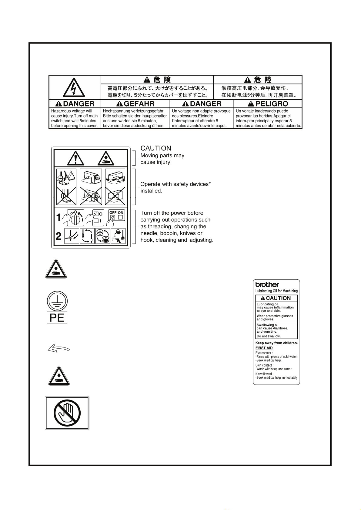
[3] Warning labels
The following warning labels appear on the sewing machine.
Please follow the instructions on the labels at all times when using the machine. If the labels have been removed or are
difficult to read, please contact your nearest Brother dealer.
1
2
3
4
Be careful not to get your hand caught when tilting back
the machine head and returning it to its original position.
Be sure to connect the ground.
If the ground connection is not secure, you run a high
risk of receiving a serious electric shock, and problems
with correct operation may also occur.
.
*Safety devices
Devices such as eye guard, finger guard,
thread take-up cover, side cover,
rear cover, solenoid cover, inner cover, outer
cover, fixed cover and gas spring support
cover
8
5
6
7
iv
Direction of operation
Be careful to avoid injury from moving parts.
Do not hold, otherwise problems with
operation or injury may occur.
BAS-326H-484, BAS-326H-484 SF
Page 7
Rear cover
Solenoid cover
Side cover
Thread take-up cover
Inner cover L
Outer cover
Fixed cover
Eye guard
Finger guard
Inner cover R
Outer cover
Fixed cover
Gas spring support cover
BAS-326H-484, BAS-326H-484 SF
3730B
v
Page 8

CONTENTS
1. NAMES OF MAJOR PARTS ................ 1
2. SPECIFICATIONS ................................ 2
3. INSTALLATION.................................... 3
3-1. Table processing diagram ................................ 3
3-2. Installing the control box................................... 4
3-3. Installing the oil pan.......................................... 4
3-4. Installing the machine head.............................. 5
3-5. Installing the LCD panel ................................... 8
3-6. Installing the two-pedal foot switch ................. 9
3-7. Connecting the cords........................................ 9
3-8. Connecting the ground wire.............................. 13
3-9. Connecting the power cord............................... 14
3-10. Installing the cotton stand...............................17
3-11. Installing the pneumatic unit ........................... 18
3-12. Adjusting the speed controller ........................ 19
3-13. Installing the eye guard .................................. 20
3-14. Installing the side cover and rear cover.......... 20
3-15. Lubrication ...................................................... 21
3-16. Installing the machine head fixing bolt ........... 22
3-17. Checking the machine head switch................ 22
4. PREPARATION BEFORE SEWING.....23
4-1. Installing the needle.......................................... 23
4-2. Threading the upper thread .............................. 24
4-3. Winding the lower thread..................................26
4-4. Installing the bobbin case................................. 27
4-5. Installing the anti-spin spring............................ 28
4-6. Thread tension.................................................. 28
4-6-1. Lower thread tension ............................... 28
4-6-2. Upper thread tension ............................... 29
4-7. Starting up ........................................................29
5. SEWING................................................30
5-1. Sewing .............................................................. 30
5-2. Using the STOP switch..................................... 31
6. CLEANING ...........................................32
6-1. Cleaning the rotary hook...................................32
6-2. Cleaning the control box air inlet ports .............32
6-3. Draining the oil ..................................................33
6-4. Checking the regulator......................................33
6-5. Cleaning the eye guard.....................................33
6-6. Checking the needle .........................................33
6-7. Lubrication.........................................................33
7. STANDARD ADJUSTMENTS ..............34
7-1. Checking the machine head switch ..................34
7-2. Adjusting the sensitivity of the thread
breakage sensor...............................................35
7-3. Thread take-up spring.......................................36
7-4. Arm thread guide R...........................................36
7-5. Adjusting the needle and rotary hook timing.....37
7-6. Adjusting the needle clearance.........................37
7-7. Adjusting the thread take-up amount................38
7-8. Adjusting the clearance between the
inner hook and the hook stopper......................38
7-9. Replacing the movable and fixed knives ..........39
7-10. Adjusting the position of the movable knife ....40
7-11. Adjusting the engagement of the movable
knife and fixed knife .......................................41
7-12. Installing the feed plate ...................................42
7-13. Adjusting the thread wiper ..............................44
7-14. Intermittent presser foot installation position
(-484 SF specifications only) ........................44
7-15. Adjusting the intermittent presser foot
(-484 SF specifications only) ........................45
7-16. Adjusting the work clamp lift amount ..............47
7-17. Adjusting the air pressure ...............................47
7-18. If processing the work clamps and the feed
plate to a shape that matches the sewing
pattern.............................................................48
8. LIST OF ERROR CODES.....................49
9. TROUBLESHOOTING.......................... 55
BAS-326H-484, BAS-326H-484 SF
Page 9
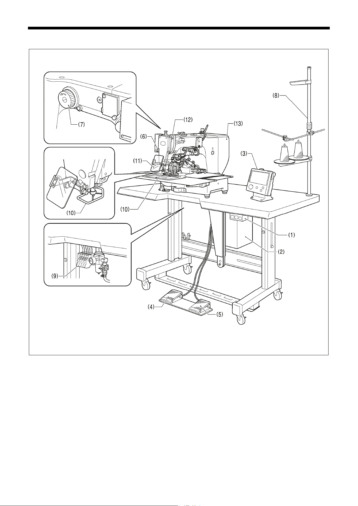
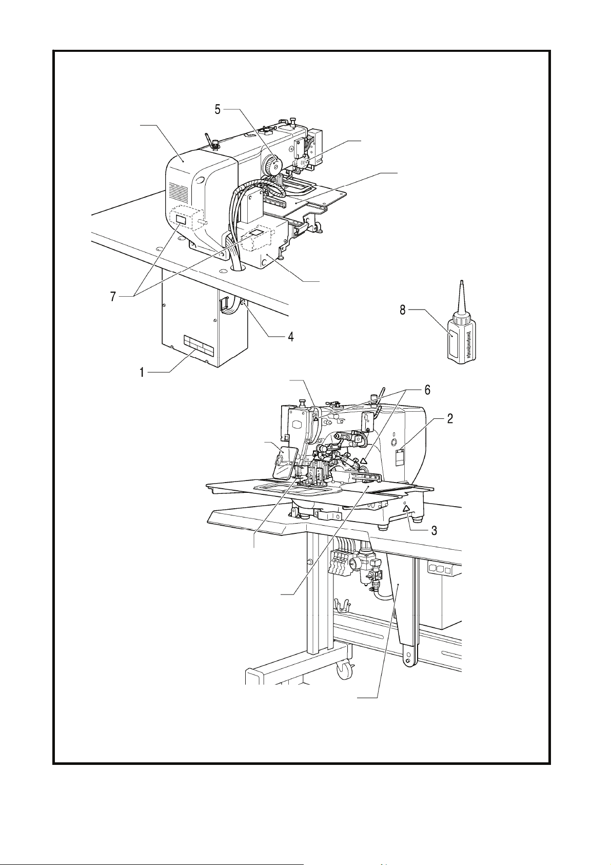
1. NAMES OF MAJOR PARTS
1. NAMES OF MAJOR PARTS
(1) Power switch
(2) Control box (10) Finger guard
(3) LCD panel (11) Eye guard
(4) Work clamp switch (12) Thread take-up cover
(5) Start switch (13) Rear cover
(6) STOP switch
(7) Pulley
(8) Cotton stand
(9) Solenoid valve
<BAS-326H-484>
<BAS-326H-484 SF>
3731B
Safety devices:
BAS-326H-484, BAS-326H-484 SF
1
Page 10
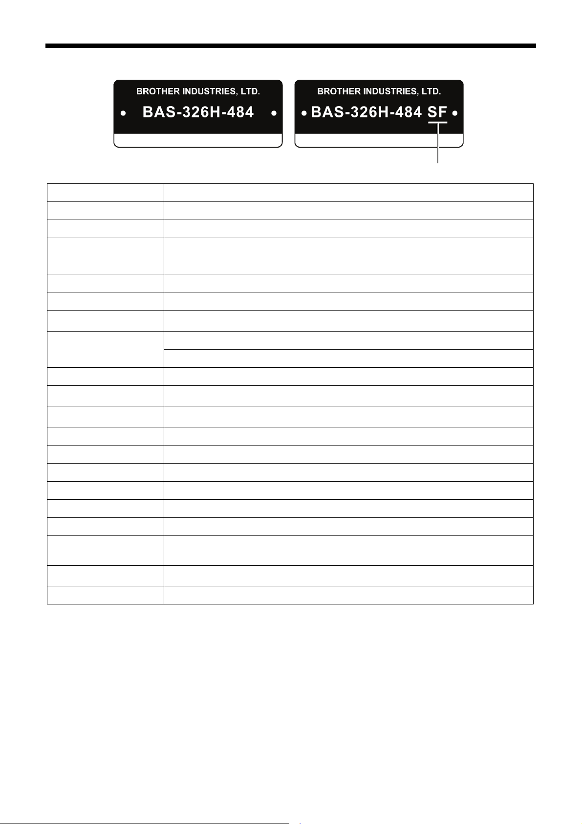
2. SPECIFICATIONS
2. SPECIFICATIONS
Sewing machine Lock stitch pattern tacking sewing machine
Stitch formation Single needle lock stitch
Max. sewing speed 2,200 sti/min
Max. sewing area (XxY) 220 x 100 mm
Feed mechanism Intermittent feed, pulse motor drive
Stitch length
Maximum No. of stitches 20,000 stitches (per program)
No. of sewing data items
that can be stored
Work clamp lift method
Work clamp height Max. 27.5 mm
Intermittent presser foot lift
amount
Intermittent presser foot
stroke
Hook Treble hook
999 (Internal memory, SD card, USB memory) (*1)
2 − 4.5 mm, 4.5 − 10 mm or 0 (Default setting 3 mm) (*2)
0.05 − 12.7 mm
Pneumatic cylinder method
Separate-type work clamp
19.5 mm (*2)
With intermittent presser foot
3714B
Wiper device Standard equipment
Thread trimmer Standard equipment
Thread take-up device Standard equipment
Cycle programs 30
Motor 550 W AC servo motor
Weights
Power source
Air pressure 0.5 MPa 1.8 l/min.
(*1) The number of data items and stitches that can be stored will vary depending on the number of stitches in each
program.
No guarantees of operation can be given for any media.
(*2) Only applicable to -484 SF specifications.
(For single-phase 110 V and three-phase 380 V/400 V, the trans box is required.)
Machine head Approx. 88 kg, LCD panel Approx. 0.8 kg
Control box 9 kg (Differs depending on destination)
Single-phase 110V / 220V / 230V, 3-phase 220V / 380V / 400V
BAS-326H-484, BAS-326H-484 SF
2
Page 11
3. INSTALLATION
3. INSTALLATION
CAUTION
Machine installation should only be carried out by a
qualified technician.
Contact your Brother dealer or a qualified electrician
for any electrical work that may need to be done.
The sewing machine head weighs approximately
88kg. The installation should be carried out by three or
more people.
Do not connect the power cord until installation is
complete.
If the foot switch is depressed by mistake, the sewing
machine might start operating and injury could result.
Hold the machine head with both hands when tilting it
back or returning it to its original position.
Furthermore, do not apply excessive force when tilting
back the machine head. The sewing machine may
become unbalanced and fall down, and serious injury
or damage to the sewing machine may result.
All cords should be secured at least 25 mm away from
any moving parts. Furthermore, do not excessively
bend the cords or secure them too firmly staples,
otherwise there is the danger that fire or electric
shocks could occur.
Be sure to connect the ground. If the ground
connection is not secure, you run a high risk of
receiving a serious electric shock, and problems with
correct operation may also occur.
Install the safety covers to the machine head and
motor.
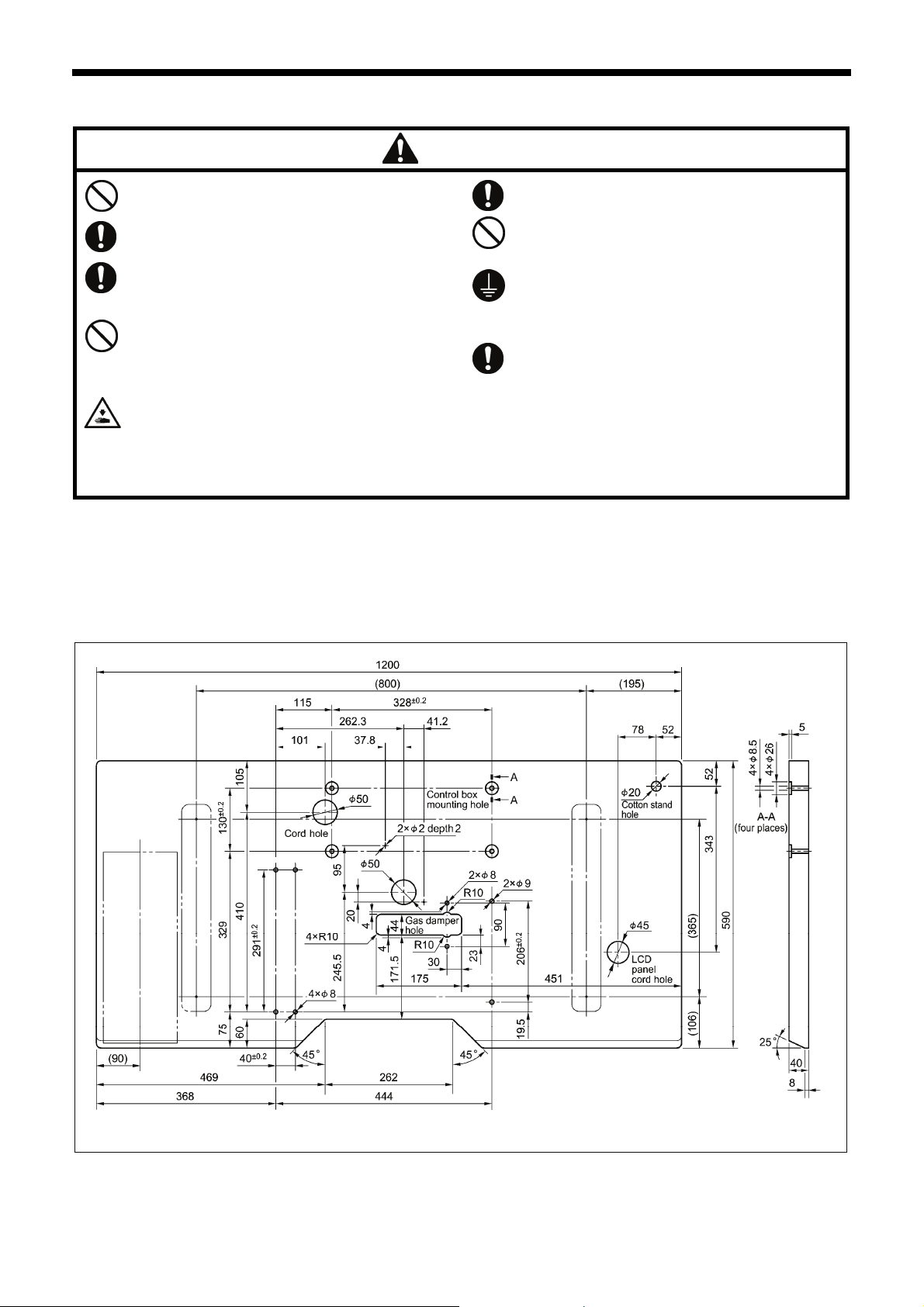
3-1. Table processing diagram
• The thickness of the table should be at least 40 mm, and it should be strong enough to bear the weight and vibration of the
sewing machine.
• Check that the control box is at least 10 mm away from the leg. If the control box and the leg are too close together, it may result
in incorrect sewing machine operation.
BAS-326H-484, BAS-326H-484 SF
3679B
3
Page 12
3. INSTALLATION
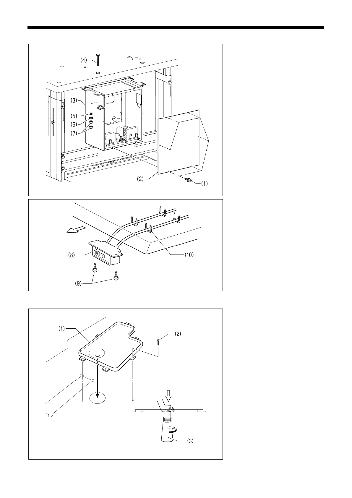
3-2. Installing the control box
Operator
3-3. Installing the oil pan
Remove the six screws (1), and then
remove the control box cover (2).
(3) Control box
(4) Bolts [4 pcs.]
(5) Plain washers [4 pcs.]
(6) Spring washers [4 pcs.]
(7) Nuts [8 pcs.]
3033B
(8) Power switch
(9) Wood screws [2 pcs.]
(10) Staples [4 pcs.]
1841B
(1) Oil pan
(2) Nails [6 pcs.]
(3) Waste oil tank
3034B
4
BAS-326H-484, BAS-326H-484 SF
Page 13
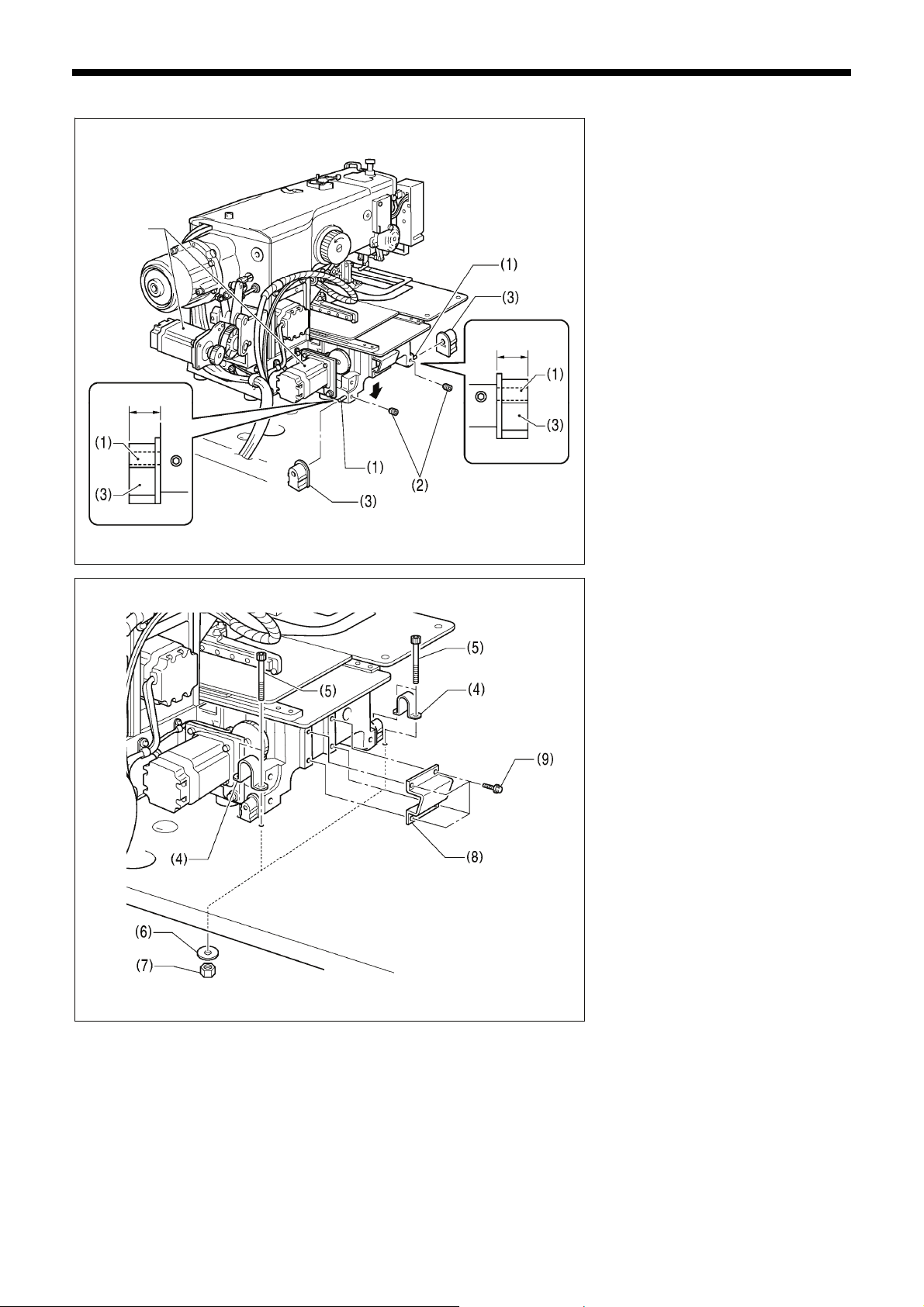
3-4. Installing the machine head
3. INSTALLATION
(1) Pins [2 pcs.]
(2) Set screws [2 pcs.]
(3) Hinge rubber assemblies [2 pcs.]
Place the machine head gently on top of
the oil pan.
Pulse motor
Approx. 20 mm
Approx. 20 mm
NOTE:
• Be careful not to get the cords
clamped between the machine head
and the oil pan.
• When holding the machine head, do
not hold it by the pulse motor. This
may cause problems with operation
of the pulse motor.
3690B
(4) Hinge holders [2 pcs.]
(5) Bolts [4 pcs.]
(6) Plain washers [4 pcs.]
(7) Nuts [4 pcs.]
(8) Head rest
(9) Bolts with washer [4 pcs.]
3691B
BAS-326H-484, BAS-326H-484 SF
5
Page 14
3. INSTALLATION
Needle plate
Work clamp arm
3431B
3432B
3521B
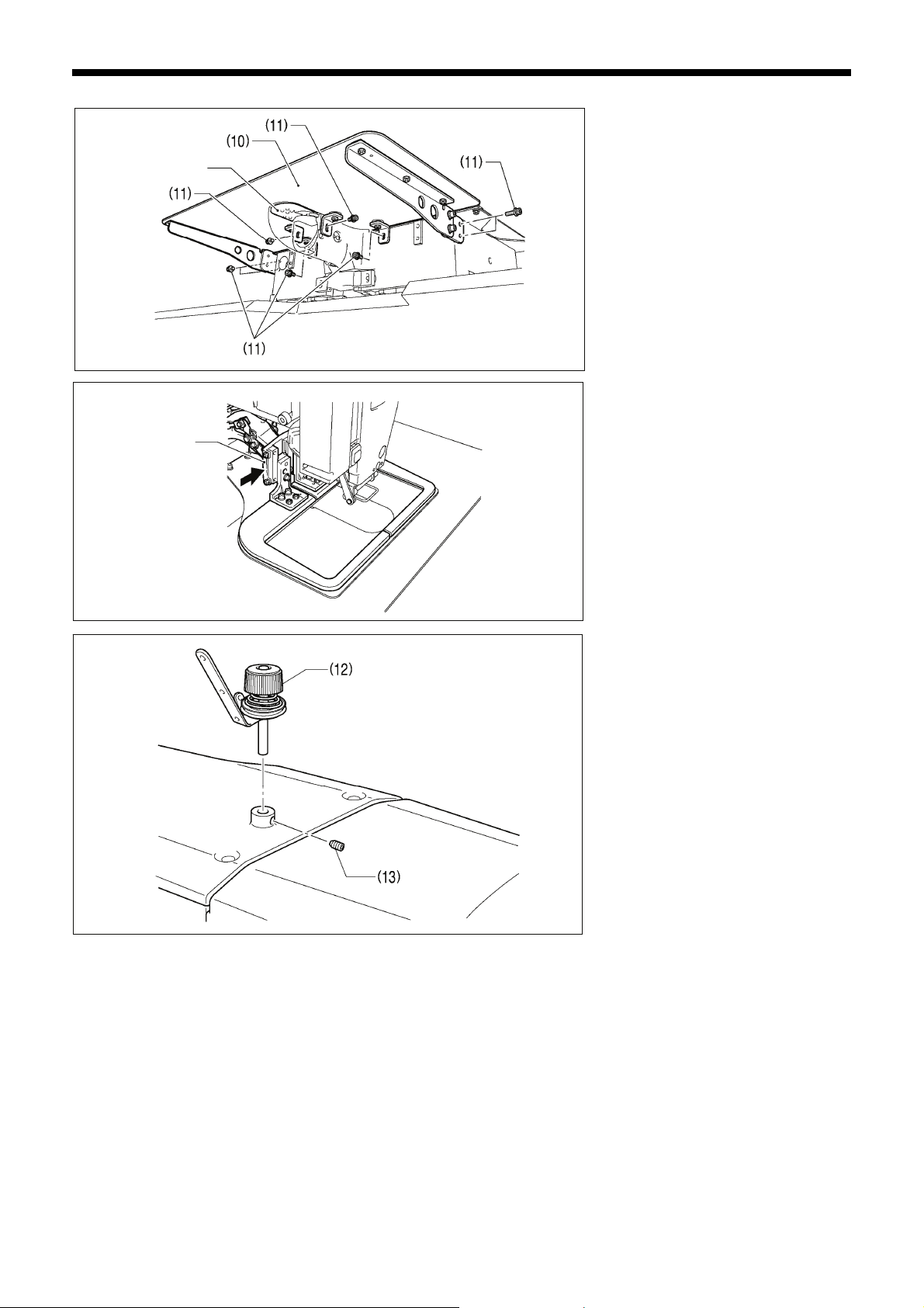
(10) Auxiliary plate
(11) Bolts with washer [8 pcs.]
Loosen the eight bolts with washer (11),
and adjust so that the auxiliary plate (10)
is 0 to 0.5 mm above the needle plate.
NOTE:
• Install the auxiliary plate (10) so that
it is horizontal.
If the auxiliary plate (10) is lower than
the needle plate, the feed plate may
get caught on the needle plate.
Move the work clamp arm all the way to
the right when looking from the front of
the sewing machine (the direction of the
arrow in the illustration), and then gently
tilt back the machine head.
NOTE:
• Three or more people should tilt
back the machine head, and it
should be tilted gently while being
held with both hands.
• Be careful not to clamp any items
such as screwdrivers under the
cushion when tilting back the
machine head.
(12) Bobbin winder tension assembly
(13) Set screw [1 pc.]
6
BAS-326H-484, BAS-326H-484 SF
Page 15
3534B
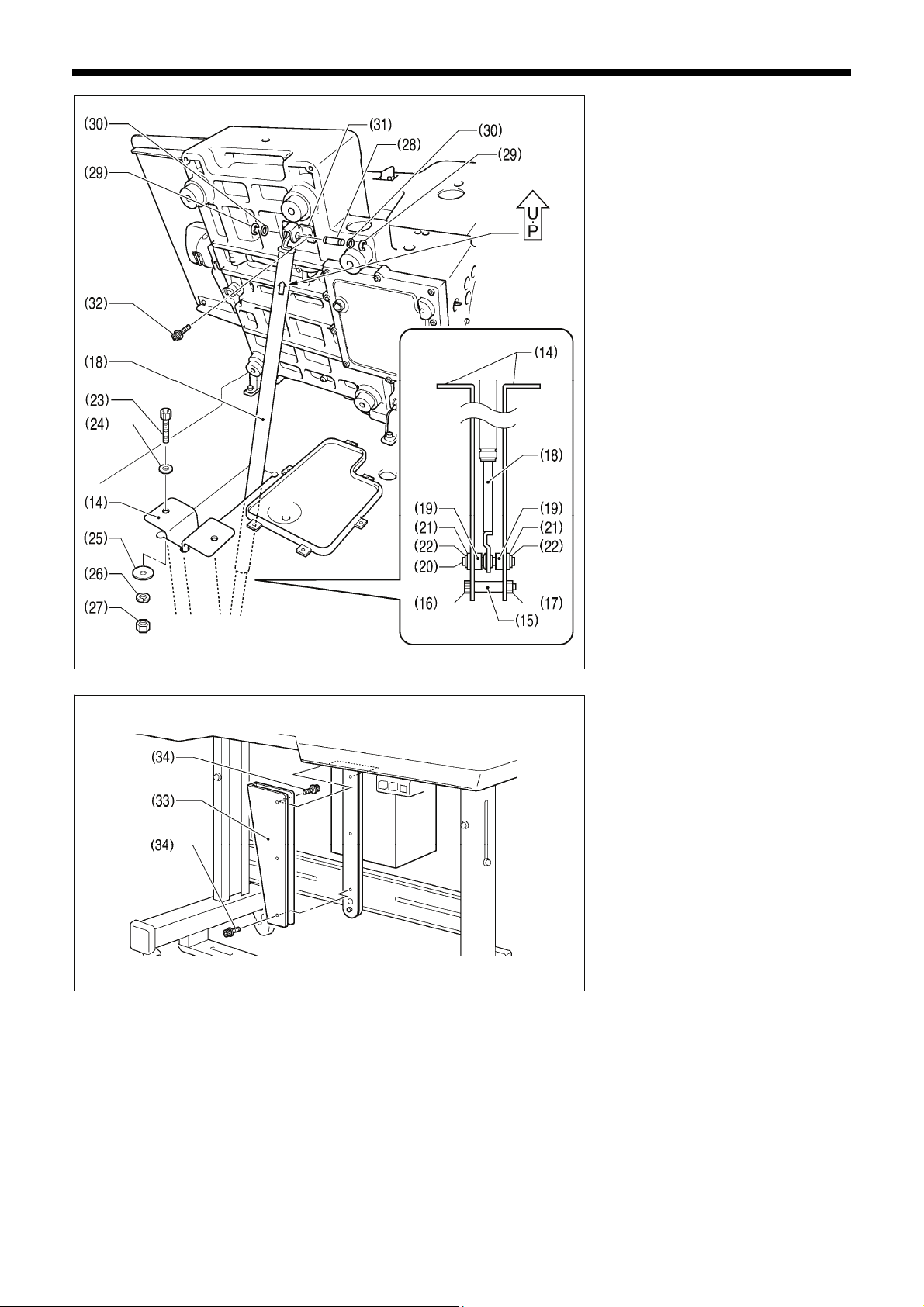
3. INSTALLATION
(14) Gas spring holders [2 pcs.]
(15) Spacer
(16) Bolt
(17) Nut
(18) Gas spring
(19) Shaft collars [2 pcs.]
(20) Gas spring shaft D
Be sure to
install so that
the side with
“UP” on it is
facing upward.
(21) Plain washers [2 pcs.]
(22) Retaining rings E [2 pcs.]
(23) Bolts [2 pcs.]
(24) Plain washers (medium) [2 pcs.]
(25) Plain washers (large) [2 pcs.]
(26) Spring washers [2 pcs.]
(27) Nuts [2 pcs.]
(28) Gas spring shaft U
(29) Retaining rings E [2 pcs.]
(30) Plain washers (small) [2 pcs.]
(31) Absorber setting plate
(32) Bolts with washer [2 pcs.]
(33) Gas spring support cover
(34) Bolts with washer [6 pcs.]
3692B
BAS-326H-484, BAS-326H-484 SF
7
Page 16
3. INSTALLATION
3-5. Installing the LCD panel
3536B
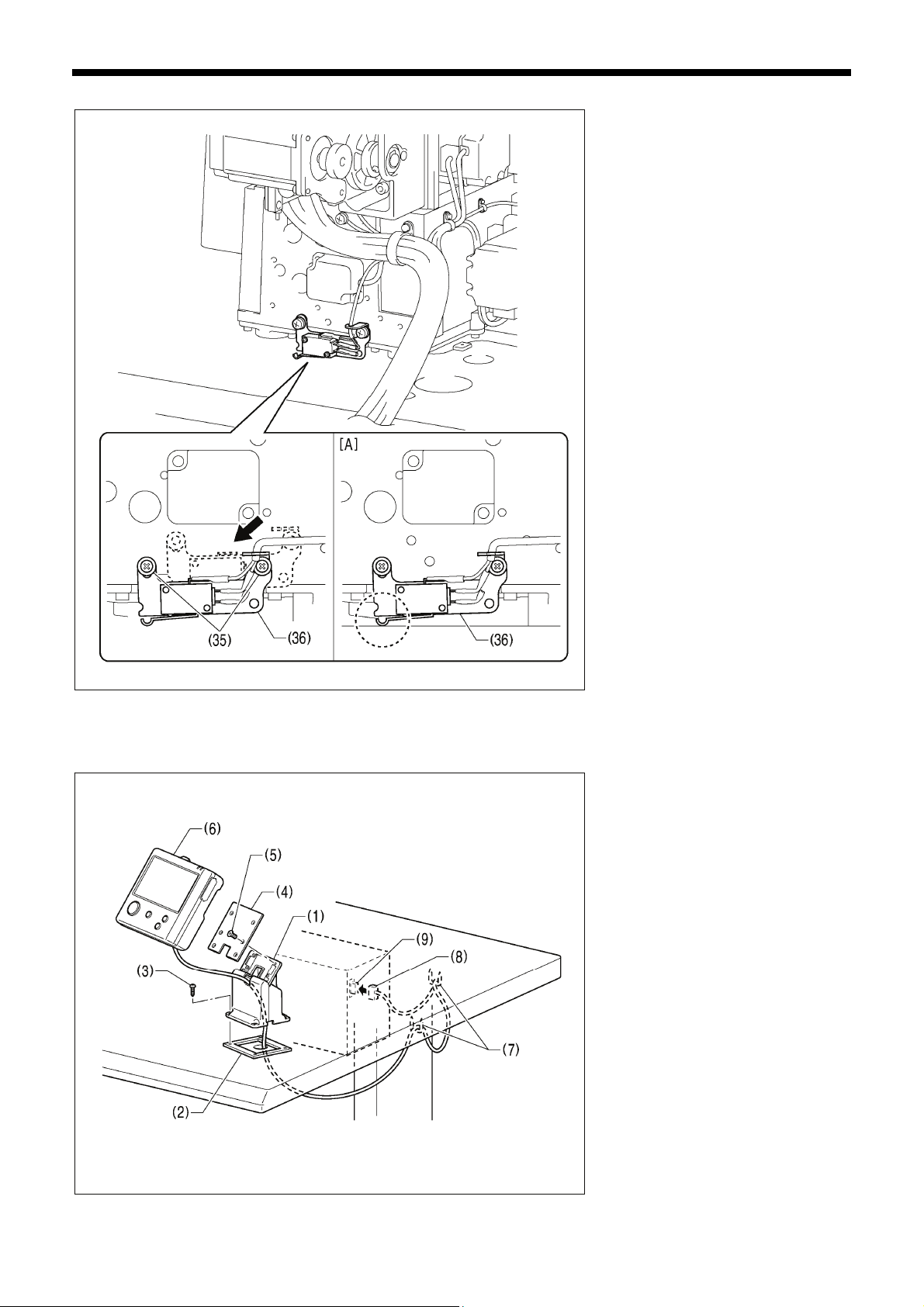
Gently return the machine head to its
original position.
1. Remove the two screws (35), and
then temporarily remove the machine
head switch assembly (36).
2. Use the two screws (35) which were
removed to install the machine head
switch assembly (36) in the position
shown in the illustration.
3. Check that the machine head switch
as turned on as shown in figure [A].
* If the machine head switch is not
turned on, adjust the installation
position while referring to “3-17.
Checking the machine head switch”.
(1) Cradle
(2) Rubber cushion
(3) Wood screws [4 pcs.]
(4) Setting plate
(5) Flat screws [4 pcs.]
(6) LCD panel
(7) Staples [2 pcs.]
8
• Pass the cord of the LCD panel (8)
through the table hole, and then insert
it into the (PANEL) connector (9) on
the side of the control box.
• Tighten the four wood screws (3) so
that the thickness of the rubber
cushion (2) is 5 mm.
3554B
BAS-326H-484, BAS-326H-484 SF
Page 17
3-6. Installing the two-pedal foot switch
3693B
3-7. Connecting the cords
.
3. INSTALLATION
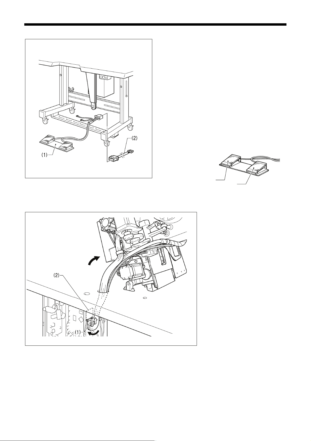
(1) Two-pedal foot switch
(2) Conversion harness
Connect the connector for the two-pedal foot switch (1) to the
conversion harness (2). Insert the conversion harness (2) into
the P15 (PEDAL) connector on the main board. (Refer to "3-7.
Connecting the cords".)
* Be sure to make the ground connection. (Refer to “3-8.
Connecting the ground wire”.)
<Two-pedal foot switch operating method>
When the work clamp switch (left) is depressed, both work
clamps are lowered, and when the start switch (right) is
depressed, the sewing machine starts sewing.
* The work clamp lowering method can be changed using
memory switch No. 002. (Refer to "2-2. List of memory
switch settings" in the "LCD Panel/Operation Panel"
Instruction Manual.)
Work clamp switch (2-step)
Start switch
4923Q
1. Gently tilt back the machine head.
2. Pass the cord bundle through the hole
in the work table.
3. Loosen the two screws (1), and then
open the cord presser plate (2) in the
direction of the white arrow and pass
the cord bundle through the opening.
4. Securely connect the connectors as
indicated in the table below.
(Refer to the next page.)
NOTE:
• Check that the connector is facing the
correct way, and then insert it firmly
until it locks into place.
• Secure the cables with cable ties and
cord clamps, while being careful not to
pull on the connector.
3694B
BAS-326H-484, BAS-326H-484 SF
9
Page 18
3. INSTALLATION
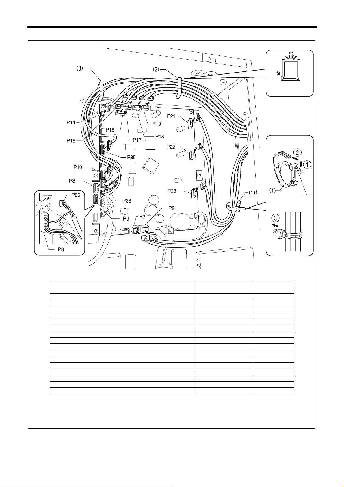
< Main board >
3695B
X pulse motor encoder [5-pin] White P17 (X-ENC) (2)
Y pulse motor encoder [5-pin] Blue P18 (Y-ENC) (2)
Intermittent presser foot pulse motor encoder [5-pin] Black *1 P19 (P-ENC) (2)
Machine head switch [3-pin] P14 (HEAD-SW) (2)
Conversion harness (two-pedal foot switch) [7-pin] White P15 (PEDAL) (2)
Machine head memory [6-pin] P16 (HEAD-M) (2)
Thread trimmer solenoid [6-pin] P2 (SOL1) (1)
Tension release solenoid [4-pin] P3 (SOL2) (1)
X pulse motor [4-pin] White P21 (XPM) (1)
Y pulse motor [4-pin] Blue P22 (YPM) (1)
Intermittent presser foot pulse motor [4-pin] Black *1 P23 (PPM) (1)
Home position sensor [12-pin] White P8 (SENSOR1) (2) (3)
STOP switch [6-pin] White P9 (HEAD) (2) (3)
Valve harness [12-pin] P35 (EX-OUT1) (2) (3)
Upper thread breakage detector [2-pin] White P36, P9(HEAD) (2) (3)
Thread trimming cylinder sensor harness [16-pin] P10 (EX-IN1) (2) (3)
Connectors
Lock the cord
clamp securely.
<Removal>
Press the tab.
<Securing>
Connection location on
main board
Cord clamps /
cable ties
NOTE: Route the X, Y and Iintermittent presser foot pulse motor harnesses so that they do not touch the power supply board
at the bottom of the control box.
*1: Only applicable to -484 SF specifications.
10
BAS-326H-484, BAS-326H-484 SF
Page 19
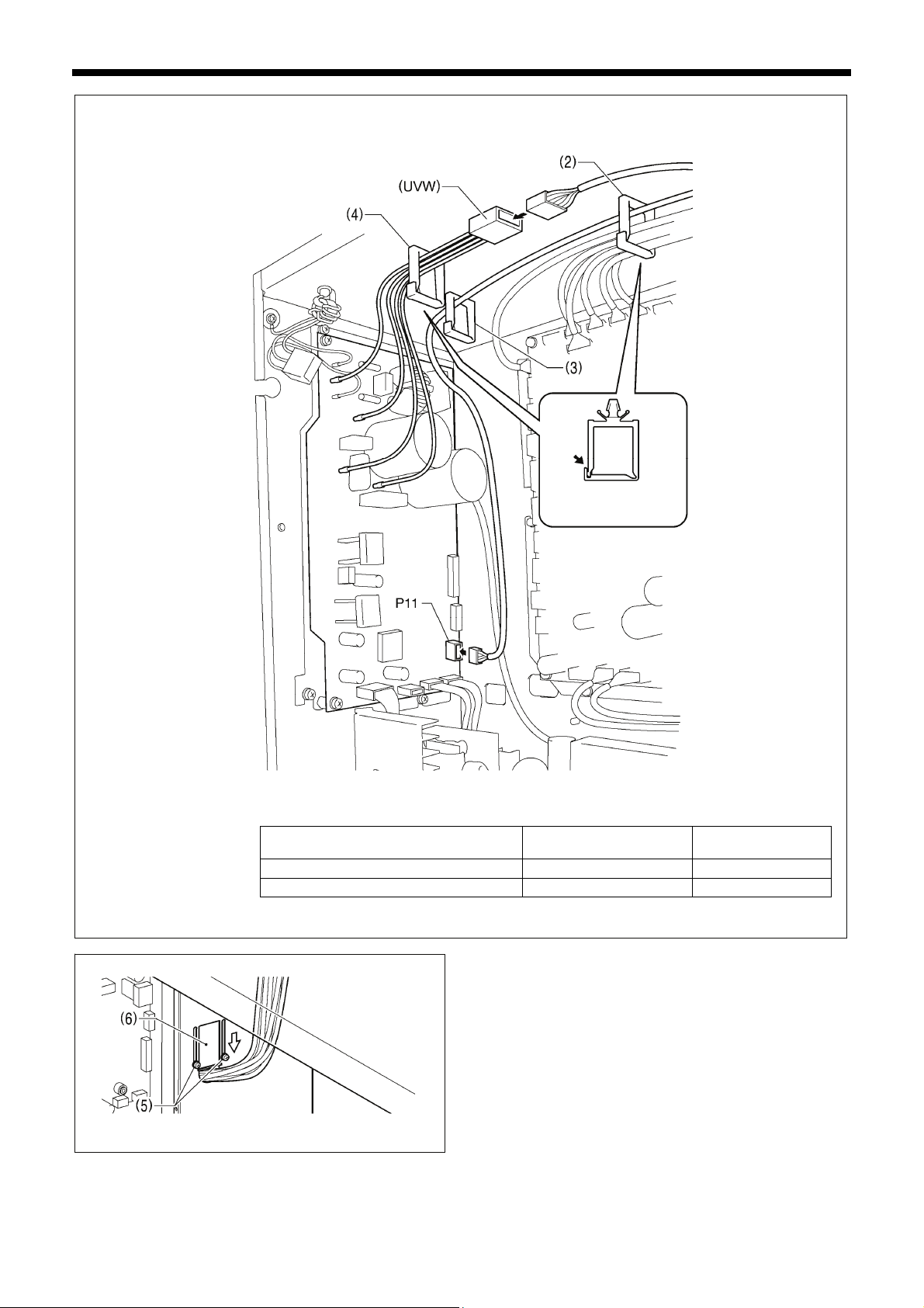
< Motor board >
3537B
Connectors
Upper shaft motor [4-pin]
Synchronizer [10-pin]
BAS-326H-484, BAS-326H-484 SF
3538B
3. INSTALLATION
Lock the cord clamps
securely.
Connection location on
motor board
(UVW)
P11(SYNC)
Cord clamps
(4)
(2) (3)
5. Close the cord presser plate (6) in the direction of the white
arrow, and secure it by tightening the two screws (5).
NOTE:
Close the cord presser plate (6) securely so that no
foreign objects, insects or small animals can get inside the
control box.
6. Check that the cords do not get pulled, and then gently return
the machine head to its original position.
11
Page 20
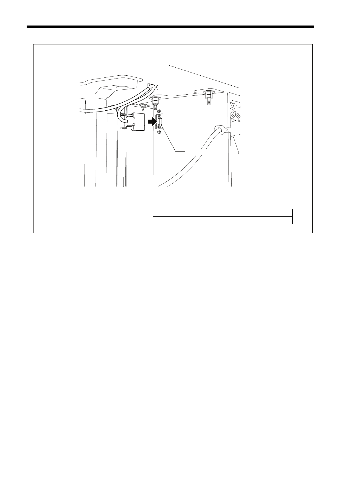
3. INSTALLATION
3557B
(PANEL)
Connector D-sub connector
LCD panel [9-pin] (PANEL)
12
BAS-326H-484, BAS-326H-484 SF
Page 21
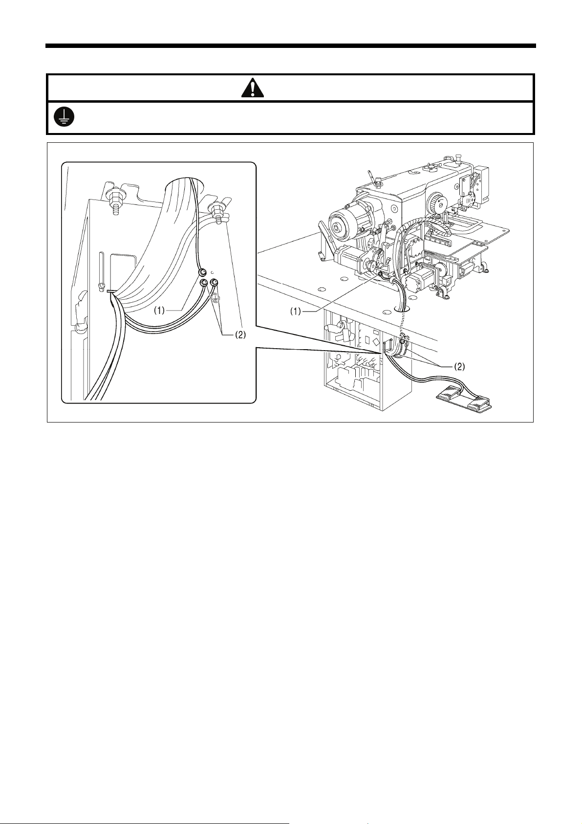
3. INSTALLATION
3-8. Connecting the ground wire
CAUTION
Be sure to connect the ground. If the ground connection is not secure, you run a high risk of receiving a serious electric
shock, and problems with correct operation may also occur.
(1) Ground wire from the machine head
(2) Ground wires from two-pedal foot switch harness (2 wires)
• Tighten the control box cover with the six screws. Check that the cords are not clamped by the cover at this time.
3696B
NOTE: Make sure that the ground connections are secure in order to ensure safety.
BAS-326H-484, BAS-326H-484 SF
13
Page 22

3. INSTALLATION
3-9. Connecting the power cord
CAUTION
Be sure to connect the ground. If the ground connection is not secure, you run a high risk of receiving a serious electric
shock, and problems with correct operation may also occur.
< Seen from underneath table >
Control box
Leg
Connect cords that match the voltage
specifications.
< EU specifications>
(1) Filter box
(2) Screws [4 pcs.]
(3) Staples [6 pcs.]
(4) Power cord
1. Attach an appropriate switch and cable
to the power cord (4). (The green and
yellow wire is the ground wire.)
2. Insert the power plug into a
properly-grounded electrical outlet.
NOTE:
• Take care when tapping in the staples
(3) to make sure that they do not pierce
the cords.
• Do not use extension cords, otherwise
machine operation problems may
result.
Green and yellow wire (ground wire)
3665B
14
BAS-326H-484, BAS-326H-484 SF
Page 23

Operator
Green and yellow wire
(ground wire)
3146B
3638B
3. INSTALLATION
<200 V system >
(1) Power switch
(2) Wood screws [2 pcs.]
(3) 3-pin power supply connector
(4) Power cord
(5) Staples [5 pcs.]
1. Attach an appropriate plug to the
power cord (4). (The green and yellow
wire is the ground wire.)
2. Insert the power plug into a
properly-grounded electrical outlet.
NOTE:
• Take care when tapping in the staples
(5) to make sure that they do not pierce
the cords.
• Do not use extension cords, otherwise
machine operation problems may
result.
3. Use the six screws to tighten the cover
of the control box. Check that none of
the cords are being clamped by the
cover at this time.
BAS-326H-484, BAS-326H-484 SF
15
Page 24

3. INSTALLATION
Operator
Green and yellow wire
(ground wire)
<100 V / 400 V system >
(1) Power switch
(2) Wood screws [2 pcs.]
3146B
2348B
(3) Transformer box
(4) Transformer box plates [2 pcs.]
(5) Screws [with washer] [4 pcs.]
(6) 3-pin power supply connector
(7) Staples [6 pcs.]
(8) Cord clamps [2 pcs.]
(9) Power cord
1. Attach an appropriate plug to the
power cord (9). (The green and yellow
wire is the ground wire.)
2. Insert the power plug into a
properly-grounded electrical outlet.
* The inside of the control box uses
single-phase power.
NOTE:
• If the ground connection is not secure,
electric shocks, operating errors or
damage to electronic components such
as PCBs may occur.
• Take care when tapping in the staples
(7) to make sure that they do not pierce
the cords.
• Do not use extension cords, otherwise
machine operation problems may
result.
3. Use the six screws to tighten the cover
of the control box. Check that none of
the cords are being clamped by the
cover at this time.
3658B
16
BAS-326H-484, BAS-326H-484 SF
Page 25

3-10. Installing the cotton stand
3640B
3. INSTALLATION
(1) Cotton stand
NOTE:
Securely tighten the nut (3) so that the
two washers (2) are securely clamped
so that the cotton stand (1) does not
move.
BAS-326H-484, BAS-326H-484 SF
17
Page 26

3. INSTALLATION
A
3-11. Installing the pneumatic unit
1. Install the pneumatic unit underneath
the work table.
(1) Solenoid valve assembly
(2) Washers [2 pcs.]
(3) Wood screws [2 pcs.]
(4) Rubber hose
NOTE:
Make sure that the pneumatic unit
does not touch the control box or the
work table leg.
Valve nos.
2. Connect each of the air tubes (5) to the valves so that all of the numbers match respectively.
The air tubes (5) marked with an A connect to the front valve connections (A), and those marked with B connect to the rear
connections (B).
3. Open the air cock (6).
3732B
fter installing the pneumatic unit,
adjust the air presser.
(Refer to “7-17. Adjusting the air pressure”.)
3733B
18
BAS-326H-484, BAS-326H-484 SF
Page 27

3-12. Adjusting the speed controller
<Adjusting the lifting and lowering speed for the work clamps>
Val ve 2
Val ve 1
3. INSTALLATION
You can adjust the lifting and lowering speed for the work
clamps using the knobs (1) and (2) on valves 1 and 2.
Valve 1 adjusts the right work clamp (3), and valve 2 adjusts
the left work clamp (4).
The knobs (1) and (2) should be adjusted so that the left and
right work clamps operate at the same speed.
• When the upper knob (1) is tightened, the lifting speed
becomes slower. When it is loosened, the lifting speed
becomes faster.
• When the lower knob (2) is tightened, the lowering speed
becomes slower. When it is loosened, the lowering speed
becomes faster.
You can operate the work clamps when the power is turned off
by pressing the manual buttons (5).
<Adjusting the thread wiper operating speed>
Val ve 3
3735B
<Adjusting the thread take-up lever operating speed>
4646M
Valve 3 is used for adjusting the operating speed of the thread
wiper (6).
To use, fully tighten both the upper and lower knobs (7) and (8),
and then loosen them both by 6 turns.
NOTE:
If the knobs (7) and (8) are tightened more than the settings
mentioned above, upper thread wiping may not be carried
out correctly.
Valve 4 is used for adjusting the operating speed of the thread
take-up lever (9).
To use, fully tighten both the upper and lower knobs (10) and
(11), and then loosen them both by 6 turns.
NOTE:
If the knobs (10) and (11) are tightened more than the
Val ve 4
settings mentioned above, the upper thread trailing length
may not be maintained correctly.
3734B
BAS-326H-484, BAS-326H-484 SF
19
Page 28

3. INSTALLATION
3-13. Installing the eye guard
CAUTION
Attach all safety devices before using the sewing machine.
If the machine is used without these devices attached, injury may result.
3-14. Installing the side cover and rear cover
3048B
3702B
3703B
(1) Bolt (loosen)
(2) Eye guard (tilt forward)
(3) Eye guard assembly
(4) Plain washers [2 pcs.]
(5) Bolts [2 pcs.]
After installing the eye guard assembly
(3), return the eye guard (2) to its original
angle, and then tighten the bolt (1) to
secure it in place.
(1) Side cover
(2) Screws [4 pcs.]
(3) Rear cover
(4) Screws [4 pcs.]
NOTE:
Be careful not to clamp the cords when
installing the side cover and the rear
cover.
20
BAS-326H-484, BAS-326H-484 SF
Page 29

3. INSTALLATION
3-15. Lubrication
CAUTION
Do not connect the power cord until lubrication is complete.
If the foot switch is depressed by mistake, the sewing machine might start operating and injury could result.
Be sure to wear protective goggles and gloves when handling the lubricating oil and grease, so that they do not get into
your eyes or onto your skin. If the oil and grease get into your eyes or onto your skin, inflammation can result.
Furthermore, do not drink or eat the lubricating oil or grease. They may cause diarrhea or vomiting.
Keep the oil out of the reach of children.
The sewing machine should always be lubricated and the oil supply replenished before it is used for the first time, and also after
long periods of non-use.
Use only the lubricating oil <JX Nippon Oil & Energy Corporation Sewing Lube N10; VG10> specified by Brother.
* If this type of lubricating oil is difficult to obtain, the recommended oil to use is <Exxon Mobil Essotex SM10; VG10>.
1. Fill the arm-side oil tank with oil.
2. Fill the bed-side oil tank with oil.
NOTE:
Be sure to fill the machine with oil
when the oil level is down to about
one-third full in the oil sight glass. If the
oil drops below the one-third level,
there is the danger that the machine
may seize during operation.
3709B 3710B
3. Remove the bobbin case and add 2-3 drops of oil to the sliding parts (1) of the outer rotary hook and inner hook.
4. If using the needle cooler (2), fill it with optional silicon oil (100 mm
2
/s). (Refer to “4-2. Threading the upper thread”.)
3682B
BAS-326H-484, BAS-326H-484 SF
21
Page 30

3. INSTALLATION
3-16. Installing the machine head fixing bolt
When transporting the sewing machine, secure the machine head to the table with the machine head fixing bolts.
(1) Plain washers [2 pcs.]
(2) Machine head fixing bolts [2 pcs.]
NOTE:
When operating the sewing machine,
remove the machine head fixing bolts.
3570B
3-17. Checking the machine head switch
1. Turn on the power.
2. Check that no error numbers appear.
<If error [E050], [E051] or [E055] is displayed>
If the machine head switch (1) is not turned on, error [E050],
[E051] or [E055] will occur.
Use the screw (2) to adjust the installation position of the
machine head switch as shown in the illustration.
22
3054B
BAS-326H-484, BAS-326H-484 SF
Page 31

4. PREPARATION BEFORE SEWING
4-1. Installing the needle
CAUTION
Turn off the power switch before installing the needle.
If the foot switch is depressed by mistake, the sewing machine might start operating and injury could result.
1. Loosen the set screw (1).
2. Insert the needle (2) in a straight line as far as it will go,
making sure that the long groove on the needle is at the
front, and then securely tighten the set screw (1).
3057B
4. PREPARATION BEFORE SEWING
BAS-326H-484, BAS-326H-484 SF
23
Page 32

4. PREPARATION BEFORE SEWING
4-2. Threading the upper thread
Thread the upper thread correctly as shown in the illustration below.
* When using threading mode for threading, the tension discs (1) will open so that the thread can be threaded more easily.
Refer to <Threading mode> (P.25)
3704B
3059B
• Turn the machine pulley (2) and raise the thread take-up (3) to its highest position before threading the upper thread.
(This will make threading easier and it will prevent the thread from coming out at the sewing start.)
• When threading the thread through the needle, allow a distance of approximately 45 mm between the needle hole and the end
of the thread.
If it is too long, the thread may become tangled, and if it is too short, the thread may pull out at the sewing start.
• If you would like to adjust the sensitivity of the thread breakage sensor, refer to "7-2. Adjusting the sensitivity of the thread
breakage sensor".
[If using a needle cooler unit]
Thread the
upper thread
Needle cooler
3558B
24
BAS-326H-484, BAS-326H-484 SF
Page 33

4. PREPARATION BEFORE SEWING
<Threading mode>
Threading mode is safe because the sewing machine will not start even when the start switch is depressed.
1
2
Turn on the power.
Touch the Thread key on the screen.
3055B
Threading the thread.
3
Ending threading mode
4
The display will return to the previous screen.
• The work clamps (and the intermittent presser foot *1) will
drop.
• The tension discs (1) will open.
Touch the OK key on the screen.
• The work clamps (and the intermittent presser foot *1) will
return to where it was before threading mode was started.
*1: The intermittent presser foot is only applicable to -484 SF specifications.
BAS-326H-484, BAS-326H-484 SF
25
Page 34

4. PREPARATION BEFORE SEWING
4-3. Winding the lower thread
Do not touch any of the moving parts or press any objects against the machine while winding the lower thread, as this may
result in personal injury or damage to the machine.
3443B
CAUTION
1. Place the bobbin onto the bobbin winder shaft (1).
2. Thread the thread as shown in the illustration, wind the
thread around the bobbin several times, and then press the
bobbin presser arm (2).
3. Turn on the power.
4. Lower the work clamps (and the intermittent presser foot)
before depressing the start switch.
Home position detection will be carried out.
5. Touch the Wind key (4) on the screen.
6. The display will switch to the thread winding mode screen.
7. Check that the needle does not touch the work clamps (and
the intermittent presser foot), and then lower the work
clamps (and the intermittent presser foot) before depressing
the start switch.
8. Keep depressing the start switch until the lower thread stops
being wound onto the bobbin.
9. Once winding of the set amount of lower thread (80 - 90% of
the bobbin capacity) is completed, the bobbin presser arm
(2) will return automatically.
10. Remove the bobbin, hook the thread onto the knife (3), and
then pull the bobbin in the direction of the arrow to cut the
thread.
11. Touch the OK key (5) to return to the previous screen.
3550B
(4)
26
(5)
BAS-326H-484, BAS-326H-484 SF
Page 35

3708B
Case A
Case B
4. PREPARATION BEFORE SEWING
Adjusting the bobbin winding amount
Loosen the screw (6) and move the bobbin presser (7).
If the thread winds onto the bobbin unevenly
Loosen the set screw (8) and move the bobbin winder
tension assembly (9) up and down to adjust.
* For case A, move the bobbin winder tension assembly
(9) down, and for case B, move it upward.
4-4. Installing the bobbin case
CAUTION
Turn off the power switch before installing the bobbin case.
If the foot switch is depressed by mistake, the sewing machine might start operating and injury could result.
3712B
1. Pull the hook cover (1) downward to open it.
2. While holding the bobbin so that the thread winds to the left, insert the bobbin into the bobbin case.
3. Pass the thread through the thread slot (2), pass it underneath the spring (3), and then pass it through the thread guide (4),
leaving a trailing-out length of about 30 mm.
4. Hold the latch on the bobbin case and insert the bobbin case into the rotary hook.
Pull
4665M
3230Q
BAS-326H-484, BAS-326H-484 SF
27
Page 36

4. PREPARATION BEFORE SEWING
4-5. Installing the anti-spin spring
If the following situations occur, operation can be improved by using an anti-spin spring.
• The lower thread becomes tangled inside the bobbin case
• Uneven thread tightening occurs at the sewing start
Installation
1. While inserting the projections on
the anti-spin spring (1) into the
grooves of the bobbin case, insert
the anti-spin spring (1).
Insert so that the higher middle
part is facing upward.
2. Push the anti-spin spring (1) to insert it
securely so that it does not lift up
above the inside edge (A) of the
bobbin case.
4715M
Removal
Use the tip of a screwdriver
or similar to remove as
shown in the illustration.
4716M
4-6. Thread tension
[Thread tension reference]
Upper thread #4 or similar
Lower thread #4 or similar
Upper thread tension (N)
Lower thread tension (N)
Pre-tension (N)
Needle DP x 17 #25
Normal sewing speed 1,300 sti/min
4-6-1. Lower thread tension
Weaker
28
2.5 − 3.0
1.0 − 1.5
0.3 − 0.6
Stronger
Adjust the lower thread tension by turning the adjusting
screw (1).
3185Q
BAS-326H-484, BAS-326H-484 SF
Page 37

4-6-2. Upper thread tension
Weaker
Weaker
4-7. Starting up
Stronger
Stronger
3706B
2979B
4. PREPARATION BEFORE SEWING
1. Turn the tension nut (1) (main tension) to adjust the
tension as appropriate for the material being sewn.
2. Use the tension nut (2) (sub tension) to adjust so that the
upper thread trailing length after thread trimming is about
45 mm.
Before turning on the power, check that the needle bar
is at the needle up stop position.
3711B
Aligned
Turn the pulley (1) in the direction of the arrow until the
ridge at the bottom of the thread take-up (2) is aligned with
the index mark.
Turn on the power.
If a program has been registered, the program number and
a preview of the sewing pattern will be displayed.
No programs are registered at the time of shipment from the
factory, and so "---" is displayed as the program number
(No.).
For details on the sewing data reading method, refer to "3.
USING STORAGE MEDIA" in the “LCD Panel/Operation
Panel” Instruction Manual.
BAS-326H-484, BAS-326H-484 SF
29
Page 38

5. SEWING
5. SEWING
Do not allow any liquids to get onto this sewing machine, otherwise fire, electric shocks or operating problems may
occur.
If any liquid gets inside the sewing machine (machine head or control box), immediately turn off the power and
disconnect the power plug from the electrical outlet, and then contact the place of purchase or a qualified
technician.
Turn off the power switch at the following times.
If the foot switch is depressed by mistake, the sewing machine might start operating and injury could result.
• When replacing the bobbin and needle
• When not using the machine and when leaving the machine unattended
Do not touch any of the moving parts or press any objects against the machine while sewing, as this may result in
personal injury or damage to the machine.
5-1. Sewing
WARNING
CAUTION
1. Turn on the power.
2. Touch the △ or ▽ key to select the number for the
program to be sewn.
* For details on reading sewing data from SD cards and
USB memory devices, refer to "3-4. Importing items of
sewing data separately" in the LCD Panel/Operation
Panel” Instruction Manual.
3. Lower the work clamps (2) and the depress the start
switch (1).
Home position detection will be carried out.
4. Place the materials under the work clamps (2).
5. Depress the work clamp switch (3).
The work clamps (2) will be lowered.
6. Depress the start switch (1).
The sewing machine will start sewing.
7. After sewing is completed, the thread trimmer will
operate. And then the work clamps (2) will be raised.
Use work clamps which will hold the material securely
3551B
so that it does not slip. If the material slips when using
the standard work clamps and feed plate, process
them so that the material does not slip.
30
3707B
BAS-326H-484, BAS-326H-484 SF
Page 39

5. SEWING
5-2. Using the STOP switch
If you press the emergency stop switch (1) to during actual sewing, an error dialog box will be displayed and the sewing
machine will immediately stop.
3111B
(2)
<Clearing>
1. Touch the Reset key (2).
• The thread will be trimmed, and then the error dialog
box on the screen will disappear and the buzzer will
stop.
2. A dialog box asking you to confirm if you want to
continue sewing will be displayed.
(3) (4)
<Continuing sewing from a stopping point>
If the thread breaks or the lower thread runs out during sewing, you can then continue sewing from the point where the
thread broke or ran out.
1
Touch "Yes" (3) to switch to the resewing standby screen.
2
3
(5) (6)
Touch the
to the position where sewing is to be resumed.
When you touch the
by 1 stitch, and when you touch the key (6), the feed will
move forward by 1 stitch.
Depress the start switch.
The sewing machine will start operating and sewing will start.
keys (5) and (6) on the screen to return
key (5), the feed will move backward
Start switch
<Returning to the sewing start position without continuing sewing>
If you do not wish to continue sewing, touch "No" (4).
・After home position detection is carried out, the mechanism will return to the sewing start position.
3655B
BAS-326H-484, BAS-326H-484 SF
31
Page 40

6. CLEANING
6. CLEANING
Turn off the power switch before carrying out cleaning.
If the foot switch is depressed by mistake, the sewing machine might start operating and injury could result.
Be sure to wear protective goggles and gloves when handling the lubricating oil and grease, so that they do not get
into your eyes or onto your skin. If the oil and grease get into your eyes or onto your skin, inflammation can result.
Furthermore, do not drink or eat the lubricating oil or grease. They may cause diarrhea or vomiting.
Keep the oil out of the reach of children.
6-1. Cleaning the rotary hook
CAUTION
4677M
Remove the bobbin case, and then remove the dust and lint
from around the shuttle.
Also wipe the bobbin to remove oil.
6-2. Cleaning the control box air inlet ports
Use a vacuum cleaner to clean the filters in the air inlet
ports (2) of the control box (1) at least once a month.
32
3715B
BAS-326H-484, BAS-326H-484 SF
Page 41

6-3. Draining the oil
6. CLEANING
6-4. Checking the regulator
Open
Close
3117B
4678M
1. Remove and empty the waste oil tank (1) whenever it is
full.
2. After emptying the waste oil tank (1), screw it back into
its original position.
1. If water collects in the bottle of the regulator (1), close
the air cock (2), and then turn the drain cock (3) in the
direction of the arrow to drain the water.
2. After draining the water, tighten the drain cock (3).
3. Open the air cock (2).
6-5. Cleaning the eye guard
6-6. Checking the needle
Wipe the eye guard clean with a soft cloth.
NOTE:
Do not use solvents such as kerosene or thinner to
clean the eye guard.
3118B
Always check that the tip of the needle is not broken and
also that the needle is not bent before starting sewing.
3119B
6-7. Lubrication
Lubricate the sewing machine while referring to "3-15. Lubrication".
BAS-326H-484, BAS-326H-484 SF
33
Page 42

7. STANDARD ADJUSTMENTS
7. STANDARD ADJUSTMENTS
CAUTION
Maintenance and inspection of the sewing machine
should only be carried out by a qualified technician.
Ask your Brother dealer or a qualified electrician to
carry out any maintenance and inspection of the
electrical system.
Turn off the power switch and disconnect the power
cord before carrying out the following operations.
If the foot switch is depressed by mistake, the sewing
machine might start operating and injury could result.
• Inspection, adjustment and maintenance
• Replacing consumable parts such as the rotary
hook
7-1. Checking the machine head switch
3547B
Hold the machine head with both hands when tilting it
back or returning it to its original position.
In addition, do not apply excessive force when tilting
back the machine head. The sewing machine may
become unbalanced and fall down, and serious injury
or damage to the sewing machine may result.
If the power switch needs to be left on when carrying
out some adjustment, be extremely careful to observe
all safety precautions.
If any safety devices have been removed, be
absolutely sure to re-install them to their original
positions and check that they operate correctly before
using the machine.
Check that the machine head switch is turned on as
shown in the illustration.
NOTE:
If the machine head switch is not turned on, errors
"E050", "E051" and "E055" will be generated.
34
BAS-326H-484, BAS-326H-484 SF
Page 43

7. STANDARD ADJUSTMENTS
7-2. Adjusting the sensitivity of the thread breakage sensor
1. Open the cover (1) and remove the upper thread from
the photo sensor (2).
2. Turn the control (3) to the right <a> until the LED (4)
illuminates.
3. Turn the control (3) to the left <b> until the LED (4)
switches off.
4. Place the upper thread into the photo sensor (2), and
close the cover (1).
NOTE:
• Thread breakages may be difficult to detect depending
on the thickness of the thread and the type of material
being sewn. In such cases, turn the control (3) to adjust
the sensitivity, or change the number of stitches for
judgment of an upper thread breakage.
* Contact the place of purchase for information on
changing the number of stitches for judgment of an
upper thread breakage.
• If foreign objects get into the photo sensor (2), it will not
be possible to detect thread breakages. Clean inside
the photo sensor (2) to keep it free from dust and other
foreign particles.
• If applying silicone to the thread, apply the silicone
between the thread breakage detector and the thread
take-up. If silicone is applied to the thread before it
passes through the photo sensor (2), the sensor
3577B
window inside the photo sensor (2) will become dirty,
and detection errors or other problems with operation
may occur.
BAS-326H-484, BAS-326H-484 SF
35
Page 44

7. STANDARD ADJUSTMENTS
7-3. Thread take-up spring
Thread take-up spring
height (mm)
Thread take-up spring
tension (N)
2 − 4
1.0 − 1.4
<Thread take-up spring height>
Loosen the set screw (1) and turn the adjuster to adjust.
Lower
Higher
4682M
<Thread take-up spring tension>
Turn the tension stud (2) with a screwdriver to adjust the
tension.
Weaker
Stronger
4683M
NOTE:
If the thread tension spring is not adjusted correctly, the upper thread trailing length will be uneven after thread trimming.
7-4. Arm thread guide R
36
The standard position of arm thread guide R (1) is when
the screw (2) is installed to the screw hole (3) on the left
side and the arm thread guide R (1) is pushed to the
right side as far as it will go.
More thread
Less thread
To adjust the position, loosen the screw (2) and then
move arm thread guide R (1).
* If upper thread breakages or poor thread tightening
occur when sewing heavy-weight materials, move arm
thread guide R (1) to the left.
(The thread take-up amount will become greater.)
* If upper thread breakages or poor thread tightening
occur when sewing light-weight materials, install the
screw (2) to the screw hole (4) on the right side, and
then move arm thread guide R (1) to the left or right to
adjust its position.
3717B
(The thread take-up amount will become smaller.)
BAS-326H-484, BAS-326H-484 SF
Page 45

7. STANDARD ADJUSTMENTS
7-5. Adjusting the needle and rotary hook timing
4667M
4685M
4686M
4687M
Turn the pulley (1) by hand in the direction of the arrow to raise the needle bar from the lowest position until the lowest
reference line on the needle bar (reference line B) is aligned with the lower edge of the needle bar bush (2), and then
loosen the two set screws (4) and move the rotary hook to adjust so that the rotary hook tip (3) is aligned with the center of
the needle.
7-6. Adjusting the needle clearance
Turn the pulley (1) in the direction of the arrow to align the rotary hook tip (2) with the center of the needle, and then loosen
the two set screws (3) and move the rotary hook forward or back to adjust so that the clearance between the needle and the
rotary hook tip (2) is 0.01 to 0.08 mm.
4688M4667M
BAS-326H-484, BAS-326H-484 SF
37
Page 46

7. STANDARD ADJUSTMENTS
7-7. Adjusting the thread take-up amount
Less thread
Thread take-up
amount (stroke)
More thread
3718B
4689M
At the time of shipment from the factory, the thread take-up amount (stroke) of the thread take-up lever (1) is adjusted to the
standard amount of 5 mm. Adjust this amount according to the sewing conditions to prevent the thread from pulling out at
the sewing start.
Adjustment method
Loosen the pre-tension nut (2), and then turn the stopper (socket bolt) (3) to adjust the extension position of the thread
take-up cylinder (4).
* If you would like to reduce the upper thread trailing amount, tighten the stopper (3).
* If you would like to increase the upper thread trailing amount, loosen the stopper (3).
NOTE:
If you make the stroke of the thread take-up lever (1) to be shorter than necessary, it will cause the upper thread trailing
length to become too short and the thread will pull out.
In addition, if the stroke is made to be longer than necessary, it will cause the upper thread trailing length to become too
long, and the thread will become tangled on the underside of the material being sewn, creating an untidy finish.
7-8. Adjusting the clearance between the inner hook and the hook
stopper
Approx.
0.8 mm
Loosen the two screws (3) and move the hook stopper setting base (4) to adjust so that the tip of the hook stopper (1) is
approximately 0.8 mm away from the needle drop surface of the inner hook (2).
Approx. 0.8 mm
4690M
38
BAS-326H-484, BAS-326H-484 SF
Page 47

7. STANDARD ADJUSTMENTS
7-9. Replacing the movable and fixed knives
1. Loosen the two bolts (1) and then remove the feed plate (2).
2. Open the hook cover, remove the two screws (3) and the four flat screws (4), and then remove the needle plate (5).
3720B 3721B
3. Remove the movable knife (6) and the fixed knife (7).
4. Install the new movable knife (6) and fixed knife (7) while referring “7-11. Adjusting the engagement of the movable knife
and fixed knife”.
* Apply grease to the outside of the movable knife collar (8) at this time.
* Install the fixed knife (7) 0.5 mm away from the needle hole plate (9).
5. Check that the movable knife (6) and fixed knife (7) cut the thread cleanly. Replace the movable knife spacer with
accessory spacers (10) (t=0.4, 0.5, 0.6, 0.7) so that the knives trim the thread accurately.
* If the knife pressure is too weak and the thread is not completely cut, use a thinner movable knife spacer (10).
* If the knife pressure is too strong and the movable knife turns stiffly, use a thicker movable knife spacer (10).
6. Apply grease to the pin (11), place it into the movable
knife connecting plate (12), and install it to the needle
plate (5).
7. Check that the needle is aligned with the center of the
needle hole.
3719B
3722B
BAS-326H-484, BAS-326H-484 SF
39
Page 48

7. STANDARD ADJUSTMENTS
7-10. Adjusting the position of the movable knife
3059B
<View from side of thread trimmer cam>
Reverse position (position where driving
lever is at its lowest point)
3351B
1. Open the top cover and tilt back the machine head.
2. Turn the pulley (1) by hand to move the needle bar to its lowest position.
3. Loosen the nut (2), tighten the set screw (5) until the collar (3) touches the inside of the groove in the thread trimmer cam
(4), and then loosen the set screw (5) by approximately 1/4 of a turn.
4. Tighten the nut (2), and then check that the collar (3) is not touching the inside of the groove in the thread trimmer cam (4).
In addition, push the driving lever (6) by hand toward the thread trimmer cam (4) until the collar (3) touches the groove of
the thread trimmer cam (4), and then check that the driving lever (6) returns smoothly to its original position when it is
released.
5. Turn the pulley (1) by hand in the direction of the arrow to move the needle bar to its lowest position, and push the thread
trimming solenoid (7) as far as it will go.
6. With the collar (3) inserted into the groove of the thread trimmer cam (4), turn the pulley (1) by hand to set the driving lever
(6) to the reverse position and so that the driving lever (6) is at its lowest point (when the thread take-up (8) is close to its
lowest position).
3355B 3350B
3352B
40
BAS-326H-484, BAS-326H-484 SF
Page 49

7. STANDARD ADJUSTMENTS
3353B
3723B
7. Loosen the two screws (9), and then remove the cover (10).
8. Loosen the bolt (11).
9. Push the movable knife (12) in the direction of the arrow to take up the play, and then move the movable knife connecting
plate (13) forward or back to adjust so that the V section (A) is aligned with the index mark (B) on the needle plate.
10. After tightening the bolt (11), check the above position once more.
11. Replace the cover (10).
7-11. Adjusting the engagement of the movable knife and fixed knife
<1>
Knife
Knife
3211Q
A. Once the movable knife (1) and fixed knife (2) are overlapping as shown in Fig. <1>, tighten the shoulder screw (3).
B. Turn the movable knife (1) while the shoulder screw (3) is still tightened. (Move in the direction of the arrow)
C. Loosen the shoulder screw (3).
D. Turn the movable knife (1) while the shoulder screw (3) is still loosened. (Move in the direction of the arrow)
Repeat above steps A Æ B Æ C Æ D Æ A four or five times to maintain the cutting performance of the knife.
4699M
Knife
Knife
4700M
BAS-326H-484, BAS-326H-484 SF
41
Page 50

7. STANDARD ADJUSTMENTS
7-12. Installing the feed plate
1
2
Touch the Settings key.
Select “Sewing Machine Adjustment”.
3
Select “Feed plate installation”.
42
BAS-326H-484, BAS-326H-484 SF
Page 51

7. STANDARD ADJUSTMENTS
4
Depress the work clamp switch (1) to lower the work clamps, and then depress the start switch (2).
・After the home position is detected and the work clamps drop, the feed mechanism will move to the feed plate
installation position and then the work clamps will rise.
5
Index
mark
4014M
3724B
Use a 2 mm diameter pin to align the holes in the X feed bracket (3) and the needle plate (4) with the two holes in the
feed plate (5), and then tighten the two bolts (6).
NOTE: Install the feed plate so that the surface with the index mark is facing upward.
End feed plate installation mode
6
When the installation is complete, touch the
OK key to exit the mode.
BAS-326H-484, BAS-326H-484 SF
43
Page 52

7. STANDARD ADJUSTMENTS
7-13. Adjusting the thread wiper
4702M
4703M
1. Close the air cock (1).
2. Loosen the two screws (4) and shift the entire solenoid setting plate (5) up or down to adjust so that the thread wiper (3) is
15 mm in front of the needle center when the thread wiper cylinder (2) is pushed up to its full stroke.
3. Loosen the screw (6) and adjust the position of the thread wiper (3) so that the distance from the thread wiper to the tip of
the needle is approximately 2 mm and the tip of the thread wiper (3) is approximately 3 mm from the center of the needle
when the thread wiper (3) passes below the needle during operation.
NOTE: Check that the thread wiper (3) does not touch the finger guard.
4. Open the air cock (1).
Open
Close
4704M
Approx. 2mm
Approx. 3mm
4705M
7-14. Intermittent presser foot installation position
(-484 SF specifications only)
Install the intermittent presser foot (1) with the screw (2)
so that the distance from the bottom of the intermittent
presser foot to the top of the needle plate is 19.5 mm
when the sewing machine is stopped and the
intermittent presser foot (1) is raised.
44
BAS-326H-484, BAS-326H-484 SF
4706M
Page 53

7. STANDARD ADJUSTMENTS
7-15. Adjusting the intermittent presser foot (-484 SF specifications only)
The intermittent presser foot stroke can be adjusted to within 2 − 10 mm by adjusting the position of the stepping clamp
connecting rod and changing the installation position of stepping clamp link.
<Changing the installation position of stepping clamp link>
1. Remove the face plate.
2. Remove the two screws (1) and the two shoulder screws (2), and then remove stepping clamp link (3).
3. Change the installation position for stepping clamp link (3) to either A, B or C above.
If the position of the stepping clamp connecting rod is adjusted as described in the following at any one of the installation
positions, the adjustment range for the intermittent presser foot stroke will as given in the following table.
5011Q5010Q
Installation position Intermittent presser foot stroke range
A
B
C
0 mm (Intermittent presser foot does not move up and
2 − 4.5mm
4.5 − 10mm
down)
4707M
BAS-326H-484, BAS-326H-484 SF
45
Page 54

7. STANDARD ADJUSTMENTS
<Stepping clamp connecting rod position adjustment>
5014Q
Index mark
3138B
5015Q
1. Loosen the screw (1), and then open the cover (2).
2. Loosen the nut (3), and then adjust the position of the stepping clamp connecting rod (4).
• When the stepping clamp connecting rod (4) is raised, the intermittent presser foot stroke will increase.
• When the stepping clamp connecting rod (4) is lowered, the intermittent presser foot stroke will decrease.
Next, adjust the needle bar and intermittent presser foot timing.
3. Turn the pulley in the direction of the arrow to raise the needle bar from the lowest position until the lowest reference line
on the needle bar (reference line B) is aligned with the lower edge of the needle bar bush (5).
(If using a DP x 5 needle, align with the second reference line from the top (reference line b).)
4. Open the top cover and loosen the two set screws (6).
5. Align the index marks of the stepping clamp cam (7) and the stepping clamp connecting rod (4), and then tighten the two
set screws (6).
Check the following after changing the intermittent presser foot stroke.
3139B 3511B
Needle plate
1. With the intermittent presser foot (1) lowered, turn the pulley in the direction of the arrow to move the intermittent
presser foot (1) to its lowest position.
2. Check that the presser foot (1) does not touch the needle plate and that the presser bar clamp (2) does not touch the
presser bar bush (3).
<If they are touching>
Remove the motor cover (4).
Loosen the nut (5), and turn the bolt (6) until it is pressing against the intermittent drive lever (7), and then adjust until
the two points mentioned above are not touching.
46
BAS-326H-484, BAS-326H-484 SF
Page 55

7. STANDARD ADJUSTMENTS
7-16. Adjusting the work clamp lift amount
The maximum lift amount for the work clamp is 27.5 mm above the surface of the needle plate.
1. Turn on the air, and then depress the work clamp switch (1) to raise the work clamps (2).
2. Loosen the two bolts (4) of the work clamp arm lever (3), and move the work clamp arm lever (3) up or down to adjust.
Max. 27.5 mm
7-17. Adjusting the air pressure
3143B5018Q
Lift up the handle (2) of the regulator (1) and then turn it to
adjust the air pressure to 0.5 MPa.
After adjustment is complete, push the handle (2)
downward to lock it.
If water has collected in the bottle of the regulator (1), turn
the drain cock (3) in the direction indicated by an arrow to
drain the water.
NOTE:
Open the air cock (4) slowly.
3726B
BAS-326H-484, BAS-326H-484 SF
47
Page 56

7. STANDARD ADJUSTMENTS
7-18. If processing the work clamps and the feed plate to a shape that
matches the sewing pattern
Process the work clamps and feed plate which match the sewing pattern, while referring to the processing diagram below.
* Values in ( ) are the recommended sizes when sewing using the maximum area (220x100 mm).
<Work clamp processing diagram>
The left and right work clamps are symmetrical.
<Feed plate processing diagram>
Recommended thickness 1.5 mm
Center of sewing area
3513B
48
[mm]
Center of sewing area
3727B
BAS-326H-484, BAS-326H-484 SF
Page 57

8. LIST OF ERROR CODES
8. LIST OF ERROR CODES
DANGER
Wait at least 5 minutes after turning off the power switch and disconnecting the power cord from the wall outlet
before opening the control box cover. Touching areas where high voltages are present can result in severe injury.
If a malfunction occurs with the sewing machine, a buzzer will sound and an error code will appear on the screen.
Follow the remedy procedure to eliminate the cause of the problem.
Switch-related errors
Code Cause of error and remedy
E010
E011
E012
E015
E016
E020
E025
E035
E050
E051
E055
E064
E065
The STOP switch was pressed.
Press the RESET key to clear the error.
The STOP switch was pressed.
Press the RESET key to clear the error.
You can press the
The STOP switch was pressed.
Press the RESET key to clear the error, and then depress the start switch to move the feed mechanism to the
home position.
The STOP switch was still being pressed when the power was turned on, or there is a problem with the STOP
switch connection.
Turn off the power, and then check that connector P9 on the main board is properly inserted.
Problem with the STOP switch connection.
Turn off the power, and then check that connector P9 on the main board is properly inserted.
The start switch was pressed without the work clamp being lowered.
First lower the work clamp.
The start switch was pressed when the power was turned on.
Release foot from the start switch.
Work clamp switch was being depressed when power was turned on.
Release foot from the switch.
Machine head tilting was detected after the power was turned on.
Turn off the power, and then return the machine head to its original position.
Check that the connector P14 on the main board is properly inserted.
Machine head tilting was detected while the sewing machine was operating.
Turn off the power, and then check that the connector P14 on the main board is properly inserted.
Machine head tilting was detected when the power was turned on.
Turn off the power, and then return the machine head to its original position.
Check that the connector P14 on the main board is properly inserted.
Touch panel was being touched when power was turned on.
Turn off the power and then turn it back on again without touching panel.
A key on the LCD panel was still being pressed when the power was turned on, or key is faulty.
Turn off the power and then turn it back on again without touching panel.
keys on the LCD panel to move the feed in order to continue sewing.
BAS-326H-484, BAS-326H-484 SF
49
Page 58

8. LIST OF ERROR CODES
Motor-related errors
Code Cause of error and remedy
E110
The needle bar is not stopped in the needle up stop position.
Turn the pulley until the point where the error display disappears.
Upper shaft did not stop at the needle up stop position when the sewing machine stopped.
E111
Turn off the power, and then check that connectors P11 and P1 on the motor board and the connector P6 on the
main board are properly inserted.
E121
Thread trimming was not completed.
Turn off the power, and then check if the cutting edges of the fixed knife and movable knife are damaged or worn.
Main motor stopped due to a problem, or resolver is faulty.
E130
Turn off the power, and then turn the pulley and check if the sewing machine has locked up. Check connectors
P11 and P1 on the motor board, P6 on the main board and P4 of the main motor are properly inserted.
E131
Resolver is not connected correctly.
Turn off the power, and then check that the connector P11 on the motor board is properly inserted.
Problem detected with main motor operation.
E132
Turn off the power, and then check that connectors P11 and P1 on the motor board, the connector P6 on the
main board and the connector P4 of main motor are properly inserted.
Main motor stopping position is incorrect.
E133
Turn off the power, and then check P11 and P1 on the motor board, P6 on the main board and P4 of main motor
are properly inserted.
Main motor is overheating, or temperature sensor is faulty. Turn off the power, and then check the main motor.
Main motor is overheating, or temperature sensor is faulty.
E150
Turn off the power, and then check the main motor.
(When sewing data with a small number of stitches (15 stitches or less) is sewn repeatedly, the main motor may
overheat and this error code may be generated.)
50
BAS-326H-484, BAS-326H-484 SF
Page 59

Feed mechanism-related errors
Code Cause of error and remedy
X-feed motor home position cannot be detected. Problem with X-feed motor or poor X home position sensor
E200
connection.
Turn off the power, and then check that connectors P17, P21 and P8 on the main board are properly inserted.
X-feed motor stopped due to a problem.
E201
Turn off the power, and then check if there are any problems in the X-feed direction.
Turn off the power, and then check that connectors P17 and P21 on the main board are properly inserted.
X-feed motor stopped due to a problem during sewing.
E204
Turn off the power, and then check if there are any problems in the X-feed direction.
Turn off the power, and then check that connectors P17 and P21 on the main board are properly inserted.
X-feed motor stopped due to a problem while moving to the sewing start position.
E205
Turn off the power, and then check if there are any problems in the X-feed direction.
Turn off the power, and then check that connectors P17 and P21 on the main board are properly inserted.
X-feed motor stopped due to a problem during test feeding.
E206
Turn off the power, and then check if there are any problems in the X-feed direction.
Turn off the power, and then check that connectors P17 and P21 on the main board are properly inserted.
Y-feed motor home position cannot be detected. Problem with Y-feed motor or poor Y home position sensor
E210
connection.
Turn off the power, and then check that connectors P18, P22 and P8 on the main board are properly inserted.
Y-feed motor stopped due to a problem.
E211
Turn off the power, and then check if there are any problems in the Y-feed direction.
Turn off the power, and then check that connectors P18 and P22 on the main board are properly inserted.
Y-feed motor stopped due to a problem during sewing.
E214
Turn off the power, and then check if there are any problems in the Y-feed direction.
Turn off the power, and then check that connectors P18 and P22 on the main board are properly inserted.
Y-feed motor stopped due to a problem while moving to the sewing start position.
E215
Turn off the power, and then check if there are any problems in the Y-feed direction.
Turn off the power, and then check that connectors P18 and P22 on the main board are properly inserted.
Y-feed motor stopped due to a problem during test feeding.
E216
Turn off the power, and then check if there are any problems in the Y-feed direction.
Turn off the power, and then check that connectors P18 and P22 on the main board are properly inserted.
Feed motor stopped due to a problem.
E230
Reduce the sewing speed or change the operation settings to the settings for heavy-weight materials.
Ask the place of purchase for details on the setting method.
8. LIST OF ERROR CODES
Work clamp-related errors
Code Cause of error and remedy
Work clamp home position cannot be detected. Problem with work clamp motor or poor work clamp home
E300
E301
position sensor connection.
Turn off the power, and then check that connectors P19, P23 and P8 on the main board are properly inserted.
Work clamp raised or lowered position cannot be detected.
Turn off the power, and then check if there are any problems in the work clamp vertical direction. Turn off the
power, and then check that connectors P19 and P23 on the main board are properly inserted.
BAS-326H-484, BAS-326H-484 SF
51
Page 60

8. LIST OF ERROR CODES
Communication and memory-related errors
Code Cause of error and remedy
Communication error was detected between the main board and the motor board when the power was turned on.
E401
Turn off the power, and then check that connector P5 on the main board and the connector P2 on the motor
board are properly inserted.
Communication error was detected between the main and the panel.
E410
Turn off the power, and then check that the connector P10 on the programmer main board inside the LCD panel,
the connector on the right side of the control box, connectors P5 and P32 on the main board and the connector
P2 on the motor board are properly inserted.
Communication error was detected between the main and the motor board.
E411
Turn off the power, and then check that the connector P5 on the main board and the connector P2 on the motor
board are properly inserted.
No storage media is inserted.
E420
Press the RESET key to clear the error.
Insert the storage media and then try again.
The program number is invalid or it has no corresponding data.
E421
Press the RESET key to clear the error.
Check that data for this program number is present.
Error occurred while reading.
E422
Press the RESET key to clear the error.
Check the data.
Error occurred while writing to storage media.
Check the storage media. It may be write-protected.
E425
There is a possibility of a failure of the storage media or free space shortage of storage media.
Press the RESET key to clear the error.
Use the specified storage media.
E427
E430
E435
E440
E445
E450
The program containing the specified program has been cleared.
Press the RESET key to clear the error.
Cannot be accessed to the main board (flash memory).
Turn off the power, and then turn it back on again.
Cannot be accessed to the programmer main board (flash memory).
Turn off the power, and then turn it back on again.
Cannot be accessed to the main board (EEPROM).
Turn off the power, and then turn it back on again.
Cannot be accessed to the programmer main board (EEPROM).
Turn off the power, and then turn it back on again.
Model selection cannot be read from the machine head detector.
Turn off the power, and then check that the connector P16 on the main board is properly inserted.
Machine head detector is not connected.
E452
Turn off the power, and then check that the connector P16 on the main board is properly inserted.
If you press the RESET key to clear the error, you can restart the machine using the backup data in the machine
head detector.
E453
E454
E471
E474
Problem with data in machine head detector.
Turn off the power, and then turn it back on again.
Problem with data in machine head detector.
Press the RESET key to clear the error and then data is recovered.
The program number is invalid or it has no corresponding data. Press the RESET key to clear the error.
Check that data for this program number is present in the internal memory.
Internal memory is full and copying is not possible.
Press the RESET key to clear the error. Delete the sewing data.
52
BAS-326H-484, BAS-326H-484 SF
Page 61

Data editing-related errors
Code Cause of error and remedy
The enlargement ratio setting caused the sewing data to extend outside the sewing area.
E500
Set the enlargement ratio again.
Press the RESET key to clear the error.
E502
The enlargement ratio caused the stitch length to exceed the maximum length of 12.7 mm.
Press the RESET key to clear the error. Set the enlargement ratio again.
Error in data.
E510
Press the RESET key to clear the error. Please try again.
If an error occurs while reading the data, revise the data.
E511
E512
No end code has been input into pattern data.
Press the RESET key to clear the error.
Number of stitches exceeds allowed maximum.
Press the RESET key to clear the error.
Extended option output number already exists.
E520
Press the RESET key to clear the error.
Change the extended option output number.
If not using the extended option output, initialize the data to clear the extended option program.
E582
E583
Memory switch version does not match.
Press the RESET key to clear the error. Read data for the same version.
User parameter version does not match.
Press the RESET key to clear the error. Read data for the same version.
Device-related errors
Code Cause of error and remedy
E600
E670
Upper thread breakage occurred. Thread the upper thread. Press the RESET key to clear the error.
Re-sewing is possible.
Problem with the lower thread detector.
Turn off the power, and then check the lower thread detector.
8. LIST OF ERROR CODES
BAS-326H-484, BAS-326H-484 SF
53
Page 62

8. LIST OF ERROR CODES
Board-related errors
Code Cause of error and remedy
E700
E701
E705
Abnormal rise in power supply voltage.
Turn off the power, and then check the input voltage.
Abnormal rise in main motor drive voltage.
Turn off the power, and then check the voltage.
Abnormal drop in power supply voltage.
Turn off the power, and then check the input voltage.
Abnormal current was detected in main motor.
E710
Turn off the power, and then check if there are any problems with the sewing machine.
Turn off the power, and then check that connectors P11 and P1 on the motor board, P6 on the main board and
P4 of the main motor are properly inserted.
E711
E730
Abnormal current was detected in pulse motor.
Turn off the power, and then check if there are any problems with the work clamp operation.
External error input (AIRSW) was detected.
Turn off the power, and then check the air pressure.
Version updating-related errors
Code Cause of error and remedy
E860
E865
E880
E881
E883
E884
E887
E888
E889
E890
No main software is present.
Install the main control software.
No motor software is present.
Install the motor control software.
Software update request is not accepted.
Turn off the power, and then turn it back on again.
Software updating did not complete normally.
Turn off the power, and then repeat the software update procedure.
No software data is present in the storage media.
Check that the software data has been saved into the correct folder.
There is a problem with the software data.
Write the correct data into the storage media.
Software updating could not be carried out. Turn off the power, and then turn it back on again.
It failed to send and receive software update file.
Please try again.
Written data to flash memory is incorrect.
Please try again.
Software updating could not be carried out.
Please try again.
Other errors
Code Cause of error and remedy
E920
Failed to read bar-code. Press the RESET key to clear the error.
If an error code that is not listed above appears or if carrying out the specified remedy does not solve the problem,
contact the place of purchase.
54
BAS-326H-484, BAS-326H-484 SF
Page 63

9. TROUBLESHOOTING
9. TROUBLESHOOTING
・ Please check the following points before calling for repairs or service.
・ If the following remedies do not fix the problem, turn off the power and consult a qualified technician or the place of
purchase.
CAUTION
Turn off the power switch and disconnect the power cord before carrying out these operations.
The machine may operate if the foot switch is depressed by mistake, which could result in injury.
Items with "*" in the "Reference" column should only be checked by a qualified technician.
Problem Cause Remedy
Sewing machine does
not start when the
power is turned on and
the start switch is
depressed.
The following parts do
not work.
・Work clamp
・Thread wiper
・Thread trimmer
cylinder
・Thread take-up lever
Work clamp does not
rise to the maximum
height.
Work clamp pressure is
too weak.
Work clamp pressure is
not uniform at front and
back of work clamp.
Reference
Check if the machine head switch cord
is disconnected.
Adjust the position of the machine head
Machine head switch does not work.
Air cock is closed. Open the air cock. P. 18
Air pressure is too weak.
Speed controller has been tightened
too far.
(applicable to thread trimmer cylinder
and thread take-up lever)
Work clamp arm lever position is
incorrect.
Air pressure is too weak.
Work clamp is tilted. Adjust the tilt of the work clamp. *
switch.
If the machine head switch is
malfunctioning, replace it with a new
one.
Adjust the regulator so that the air
pressure is about 0.5 MPa.
Work clamp:
Adjust the speed controller by
loosening it 4 turns from the
fully-tightened position.
Adjust the speed controller by
loosening it 6 turns from the
fully-tightened position.
Adjust the position of the work clamp
arm lever.
Adjust the regulator so that the air
pressure is about 0.5 MPa.
P. 10
P. 8
P. 34
P. 47
P. 19
P. 19
P. 47
P. 47
The thread wiper is obstructing the
Thread wiper does not
operate correctly.
needle.
Thread wiper position is incorrect.
(*1) Refer to the “LCD Panel/Operation Panel” Instruction Manual.
BAS-326H-484, BAS-326H-484 SF
Adjust the height of the thread wiper. P. 44
Adjust the operating stroke of the
thread wiper.
Adjust the operating stroke of the
thread wiper.
(Continued on next page)
P. 44
P. 44
55
Page 64

9. TROUBLESHOOTING
Problem Cause Remedy
Lower thread winds to
one side.
Lower thread winding
amount is incorrect.
Thread unraveling at
sewing start.
Reference
Height of bobbin winder tension
assembly is incorrect.
Bobbin presser position is incorrect.
Needle is too thick.
Upper thread trailing length is too short.
Amount of lower thread being fed out
from bobbin is too small.
Sewing start speed is too fast. Adjust the sewing start speed. (*1)
Adjust the height of the bobbin winder
tension assembly.
Adjust the position of the bobbin
presser.
Select a needle that is suitable for the
sewing conditions.
When threading the thread through the
needle, allow a distance of
approximately 45 mm between the
needle hole and the end of the thread.
Adjust the sub-tension so that the
upper thread trailing length after thread
trimming is approximately 45 mm.
Increase the stroke of the thread
take-up lever.
* Adjusting the stroke of the thread
take-up lever should be carried out
also if adjusting the sub-tension fails
to prevent the thread from pulling
out.
Set the feeding amount to
approximately 30 mm.
P. 27
P. 27
P. 28
P. 24
P. 29
P. 38
P. 27
Skipped stitches occur.
Rotary hook tip is missing. Replace the part. *
Needle is too thin.
Needle is too thick.
Needle is bent. Replace the needle. P. 23
Needle is not installed correctly.
Clearance between needle and rotary
hook tip is too large.
Needle and rotary hook timing is
incorrect.
Material is flapping.
Select a needle that is suitable for the
sewing conditions.
Install the needle so that it faces
correctly.
Adjust the needle clearance. P. 37
Adjust the timing. P. 37
Replace the needle hole plate with one
with a smaller needle diameter.
Use a thinner feed plate.
* Recommended thickness: 1.5 mm
Process the work clamps and the feed
plate into shapes that can hold the
material near the seam.
Adjust the intermittent height of the
intermittent presser foot.
(-484 SF specifications only)
P. 28
P. 23
P. 48
*
(*1)
56
(Continued on next page)
BAS-326H-484, BAS-326H-484 SF
Page 65

9. TROUBLESHOOTING
Problem Cause Remedy
Upper thread is
breaking.
Lower thread is
breaking.
Reference
Thread is too thick for the needle.
Needle is not installed correctly.
Thread is not threaded correctly. Thread the thread correctly.
Damage or burring in parts such as the
rotary hook, hook stopper, needle hole
plate, needle or thread path.
Needle and rotary hook timing is
incorrect.
Upper thread tension is too strong. Reduce the upper thread tension. P. 29
Thread take-up spring tension is too
strong.
Thread breaks due to heat.
Damage to the needle hole plate or
bobbin case.
Lower thread tension is too strong. Reduce the lower thread tension.
Select a thread which is suitable for the
needle.
Install the needle so that it faces
correctly.
Repair the respective part by buffing it.
Alternatively, replace the part.
Adjust the timing. P. 37
Reduce the tension of the thread
take-up spring.
Use a needle cooler unit.
Reduce the sewing speed.
Repair the respective part by buffing it.
Alternatively, replace the part.
P. 28
P. 23
P. 24
*
P. 36
P. 21, 24
(*1)
*
P. 28
Needle breaks.
Upper thread is not cut.
Lower thread is not cut.
Needle is bent. Replace the needle. P. 23
Needle is too thin.
Needle and rotary hook tip are
touching.
Needle and rotary hook timing is
incorrect.
Feed timing is too slow. Advance the feed timing. *
Movable knife is blunt.
Fixed knife is blunt.
Movable knife is not picking up the
upper thread.
Movable knife is not picking up the
needle thread because the last stitch is
being skipped.
Lower thread tension is too weak. Increase the lower thread tension.
Select a needle that is suitable for the
sewing conditions.
Adjust the needle clearance. P. 37
Adjust the timing. P. 37
Replace the movable knife with a new
one.
Sharpen the fixed knife or replace it
with a new one.
Adjust the timing. P. 37
Adjust the standby position of the
movable knife.
Refer to "Skipped stitches occur". P. 56
P. 28
P. 39
P. 39
P. 40
P. 28
(Continued on next page)
BAS-326H-484, BAS-326H-484 SF
57
Page 66

9. TROUBLESHOOTING
Problem Cause Remedy
Upper thread is not
tight.
Needle is too thin.
Hole diameter in needle hole plate is
too small.
Feed plate is too thin.
Hole diameter of intermittent presser
foot is too small.
(-484 SF specifications only)
Sliding parts of outer rotary hook and
inner hook have little or no sewing
machine oil.
Damage or burring in parts such as the
rotary hook, hook stopper, needle hole
plate, needle or thread path.
Select a needle that is suitable for the
sewing conditions.
Replace the needle hole plate with one
with a larger hole diameter.
Use a thicker feed plate.
*Recommended thickness: 1.5 mm
Replace the intermittent presser foot
with one with a larger hole diameter.
Lubricate the felts for the sliding parts
of the outer rotary hook and inner hook.
Repair the respective part by buffing it.
Alternatively, replace the part.
Lower thread tension is too strong. Reduce the lower thread tension.
Increase the upper thread tension.
Upper thread tension is too weak.
*Adjust the upper thread tension after
adjusting the lower thread tension.
Thread take-up spring tension is too
weak.
Increase the tension of the thread
take-up spring.
Adjust the forward-back clearance
Upper thread does not release
correctly from hook stopper.
between the tip of the hook stopper
and the surface of the inner hook
needle drop section to approximately
0.8 mm.
Reference
P. 28
P. 21
*
P. 28
P. 29
P. 36
P. 38
0573M
Lower thread is not
tight.
0574M
Uneven thread
tightening at the sewing
start.
Poor seam finish on
underside of material at
the sewing start.
Upper thread trailing
length is irregular.
Feed timing is too fast. Retard the feed timing. *
Intermittent height of intermittent
presser foot is too low.
(-484 SF specifications only)
Lower thread tension is too weak. Increase the lower thread tension.
Adjust the intermittent height of the
intermittent presser foot.
(*1)
P. 28
Reduce the upper thread tension.
Upper thread tension is too strong.
*Adjust the upper thread tension after
P. 29
adjusting the lower thread tension.
Bobbin spinning. Use an anti-spin spring.
P. 28
Adjust the sub-tension so that the
upper thread trailing length after thread
P. 29
trimming is approximately 45 mm.
Reduce the stroke of the thread
Upper thread trailing length is too long.
take-up lever.
* Adjusting the stroke of the thread
take-up lever should be carried out
P. 38
also if adjusting the sub-tension fails
to improve the seam finish.
Movable knife is blunt.
Fixed knife is blunt.
Replace the movable knife with a new
one.
Sharpen the fixed knife or replace it
with a new one.
P. 39
P. 39
Sub-tension is too weak. Adjust the sub-tension. P. 29
58
Thread take-up spring tension is too
weak.
BAS-326H-484, BAS-326H-484 SF
Increase the tension of the thread
take-up spring.
P. 36
Page 67

INSTRUCTION MANUAL
* Please note that the contents of this manual may differ slightly from the actual product purchased as a result of product improvements.
© 2016 Brother Industries, Ltd. All Rights Reserved.
This is the original instructions.
BAS-326H-484, BAS-326H-484 SF
I5111075B E
2016.03. B (1)
 Loading...