

Page 1
Electronically Programmable lockstitch Machine
with
Cylinder Arm Profile Sll
Service manual
Page 2
CONTENTS
1.
MECHANISM
4.
STANDARD
ADJUSTMENTS
Needle bar, thread take-up, lower shaft,
D
m
11
m
m
m
fJ
m
m
2. DISASSEMBLY PROCEDURES
shu~tle
and
Work clamp mechanism (1)
Work clamp mechanism (2)
Work clamp mechanism (3)
Feed
mecha.nism
Feed
mechanism
Intermittent-presser
Intermittent-presser
Thread trimming mechanism
Thread
Thread wiper mechanism
Thread winding mechanism
Lubrication
hook mechanism
(X
(Y
release
mechanism
.......................
axis)
..............
axis)
..............
foot
mechanism (1)
foot
mechanism (2)
..............
..........
............
............
............
....
....
............
.............
............
D Covers . . . . . . . . . . . . . . . . . . . . . . . . . . 8
PJ-1
Work clamps (solenoid type) . . . . . . . . . . . 10
PJ-2
Work clamps (pneumatic type) . . . . . . . . .
11
Lower shaft . . . . . . . . . . . . . . . . . . . . . . .
EJ
Longitudinal feed
D)
Traverse
GJ
Thread wiper . . . . . . . . . . . . . . . . . . . . . . 15
fJ
I nterm
[;]
Needle bar
D)
Work clamp
ml
Thread trimming . . . . . . . . . . . . . . . . . . . 19
feed
itti
nt-presser
m Intermittent-presser
1m
Upper shaft . . . . . . . . . . . . . . . . . . . . . . .
3. ASSEMBLY
PROCEDURES
(Y
axis) . . . . . . . . . . . . . 13
(X axis) . . . . . . . . . . . . . . . . 14
foot
. . . . . . . . . . . . . . 16
........................
lifter
and
thread
release
. . . . . . . 18
foot
lifter.
. . . . . . . . . . 20
AND
ADJUSTMENT
11
12
17
21
D Upper shaft . . . . . . . . . . . . . . . . . . . . . . . 22
PJ
Intermittent-presser
11
Needle bar . . . . . . . . . . . . . . . . . . . . . . . . 24
E)
Intermittent-presser
1!1
Work clamp
G)
Thread
fJ
Traverse feed (X axis) . . . . . . . . . . . . . . . .
[;]
Longitudinal feed (Y axis) . . . . . . . . . . . . . 32
DJ
Lower shaft
1m
Work clamp arm
lifter
trimming
and
m Thread wiper
1m
Intermittent-presser
foot
lifter.
. . . . . . . . . . 23
foot
. . . . . . . . . . . . . . 25
and
thread
release
. . . . . . .
. . . . . . . . . . . . . . . . . . . 29
relevant . . . . . . . . . . . . . . 33
and
relevant . . . . . . . . . . . 34
......................
foot
. . . . . . . . . . . . . . 38
27
30
36
Ill Covers and relevant . . . . . . . . . . . . . . . . . . 39
D Adjustment
of
needle-bar height . . . . . . . . . 42
D
6 Matching the needle
with
the
tip
of
1
11
2
2
3
3
4
4
5
5
6
6
7
Adjustment
needle and the
EJ
Adjustment
the driver . . . . . . . . . . . . . . . . . . . . . . 43
DJ
Adjustment
thread guide
G)
Adjustment
fJ
Adjustment
[;]
Adjustment
D) Adjustment
foot
lift
ml
Adjustment
m Adjustment
and
feed timing . . . . . . . . . . . . . . . . . . 49
16
Adjustment
Ill Adjustment
release
timing . . . . . . . . . . . . . . . . . . . .
Ill Adjustment
mJ
Adjustment
1m
Adjustment
position . . . . . . . . . . . . . . . . . . . . . . . 53
5.
HOW TO
D How
fJ
How
to
make up the clamping type
to
make up the
the shuttle hook . . . . . . . . 42
of
clearance between the
tip
of
the shuttle hook . . . 43
of
the needle receiver
of
the shuttle hook
.....................
of
the
work
clamp
of
the moving blade . . . . . . . . . 45
of
the
presser
of
the intermittent-presser
.......................
of
the thread
of
the needle-stop position
of
the original
of
the upper thread
of
the backlash . . . . . . . . . . . . 52
of
the thread trimming
of
the
work
MAKE
foot
wiper.
clamp
UP
cassette
of
lift
. . . . . . . . 45
. . . . . . . . . . 47
. . . . . . . . . 48
point
. . . . . . . . . 50
cam
lifter
base
THE PRESSER
presser
type
presser
. . . . 53
. . . 56
44
47
51
. . 54
fl
II
II
I
I
I
II
6.
ADJUSTMENT
APPLIANCES
Description on fuse
D
Voltage measurement
PJ
LEOs
on
PCB
11
How
m
m
m
to
Description
Description
7.
TROUBLESHOOTING LIST
......................
use
the DIP switch . . . . . . . . . . . . .
of
each
on
OF ELECTRIC
........•.........
................
connector
control box
..........•
.............
.....
58
59
60
61
63
65
66
I
I
I
8. SPARE PARTS LIST
9.
CONTROL
DIAGRAM
10. TROUBLESHOOTING
FLOW
11. COUNTERMEASURES
CIRCUIT
..................
CHART
...........
BLOCK
..............
..........
69
70
71
78
Page 3
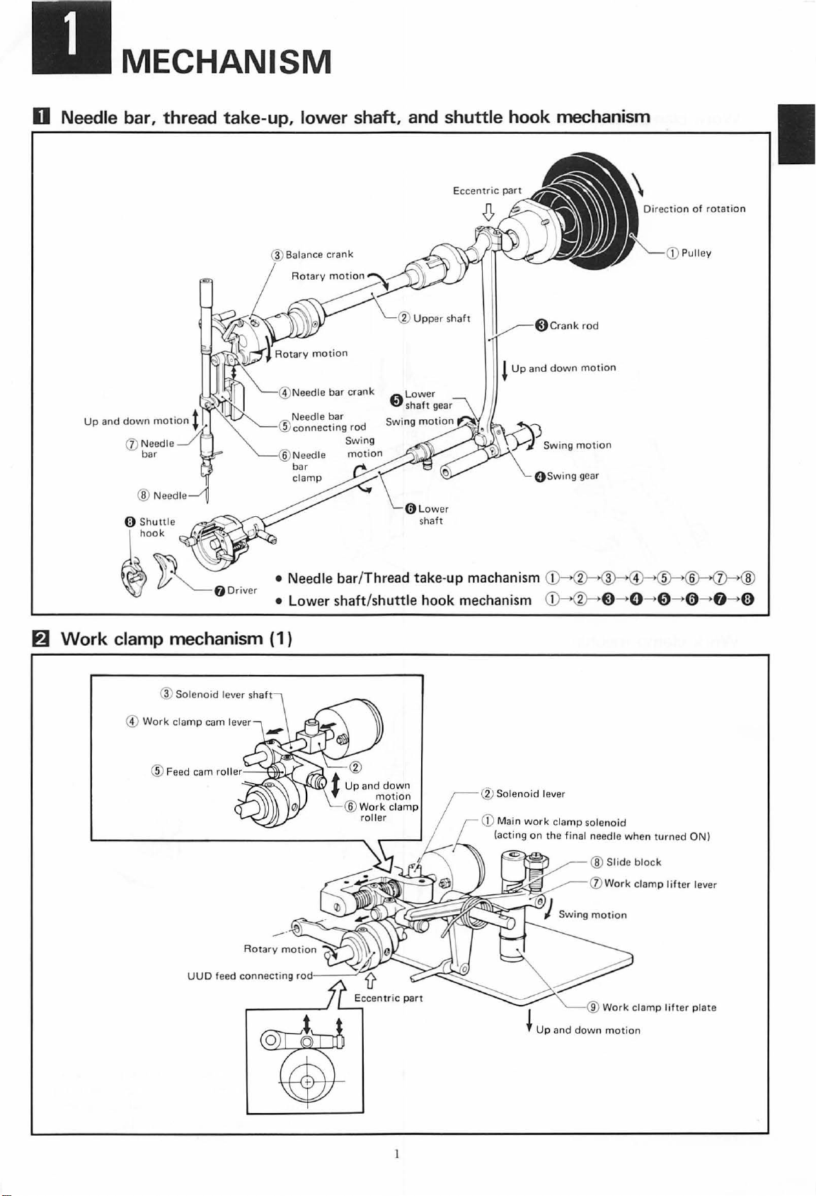
MECHANISM
D Needle bar, thread take-up, lower shaft,
a
W
(j) Needle
bar
and
shuttle hook mechanism
!
Up
and
down
lo
wer
sha
ft
gear
Swing
O Swing gear
motion
motion
Direction
of
Pulley
rotation
fl
Work
•
•
clamp mechanism ( 1 )
®Sol
enoid
lever shaft
@
Work
clamp
cam lever
Needle
Lower
bar/Thread
shaft/shuttle
take-up
hook
machanism
mechanism
@ Sol
enoid
CD
Main
(acting
1 2 3 4 5 6 7 ®
(j)-->®--->
lever
work
clamp solenoid
on
the final needle
~-0-0-0
when
turned
ON)
--+8--+
(l)
I ®
t
Up
and
down motion
Work
clamp
lifter
plate
Page 4
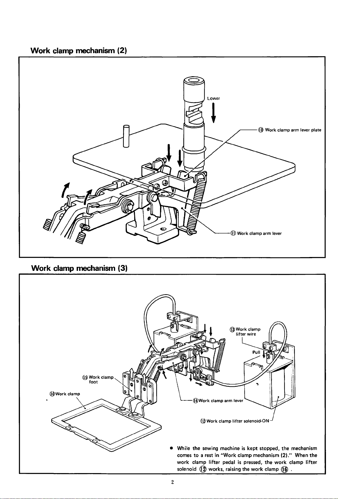
Work
clamp mechanism (2)
Work
clamp mechanism (3)
~--@
Work clamp arm lever plate
@Work
foot
clamp
@Work
• While
the
sewing machine
to
comes
work clamp lifter pedal
solenoid
a rest in "Work clamp mechanism (2)
@works,
2
clamp
lifter
solenoid-ON
is
kept
stopped,
is
pressed,
raising the work clamp @ .
the
work clamp lifter
the
mechanism
."
When
the
Page 5
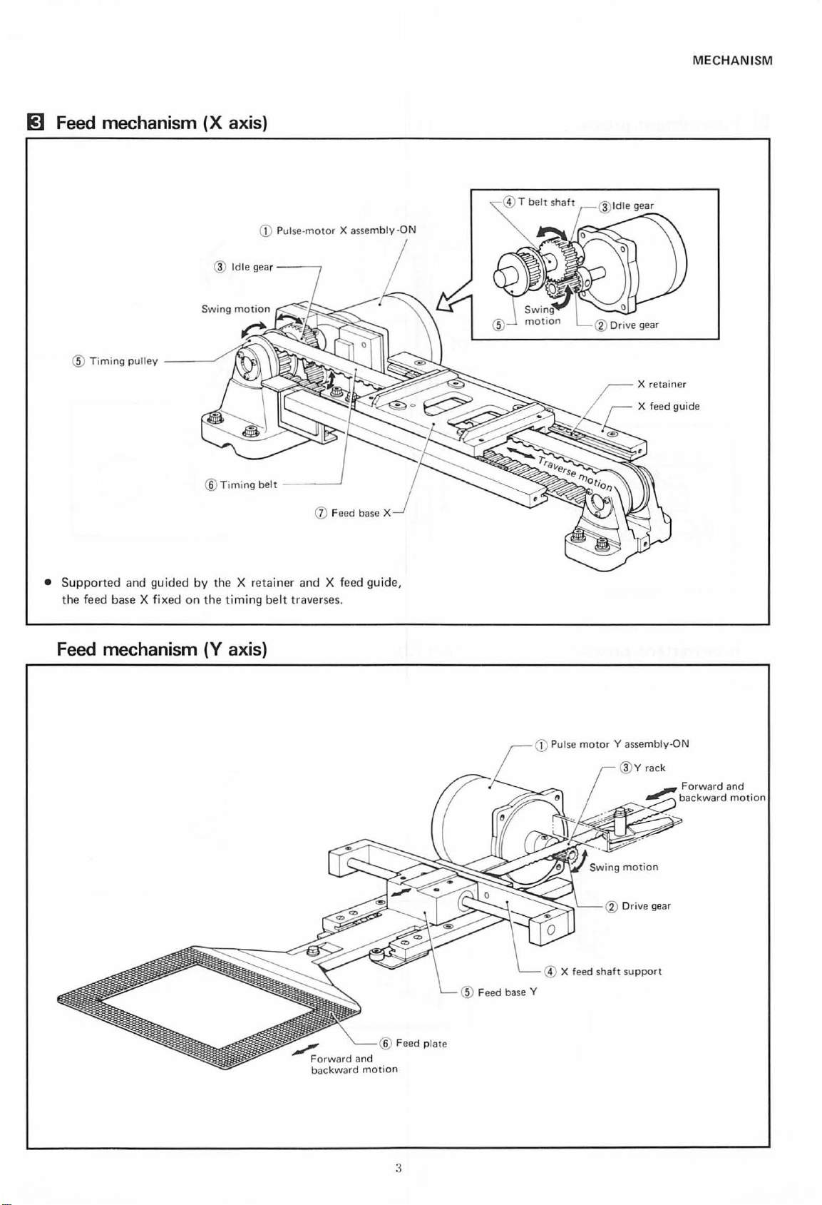
RJ
Feed mechanism
@ T imi
ng
pulley
__
_
(X
®
__.,
axis)
Idle
gear--
--,
MECHANISM
T
belt
shaft
X retai
ner
•
Support
the
ed and guid
feed
base
X fixed
Feed mechanism
ed
®
Timing
by
the X reta
on
the
timing belt traverses.
(Y
axis)
belt
--
iner
----'
(j)
and
X feed guid
Feed base X
e,
CD
Pulse
motor
Y assembly·ON
@v
rack
~
F
orwa
backward
rd and
motion
® Feed
pla
te
3
Page 6
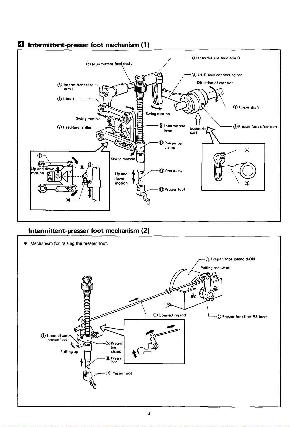
El
Intermittent-presser foot mechanism {1)
®Intermittent
arm L
(j) Link L
@ Feed-lever roller
feed
-----@Intermittent
Direction of rotation
::)~
~-"'----@Intermittent
lever
feed arm R
~CD
Upper shaft
®Presser
foot lifter cam
Intermittent-presser foot mechanism {2)
•
Mechanism
for raising the presser foot.
@ Intermittent
presser lever
\.
4
Page 7
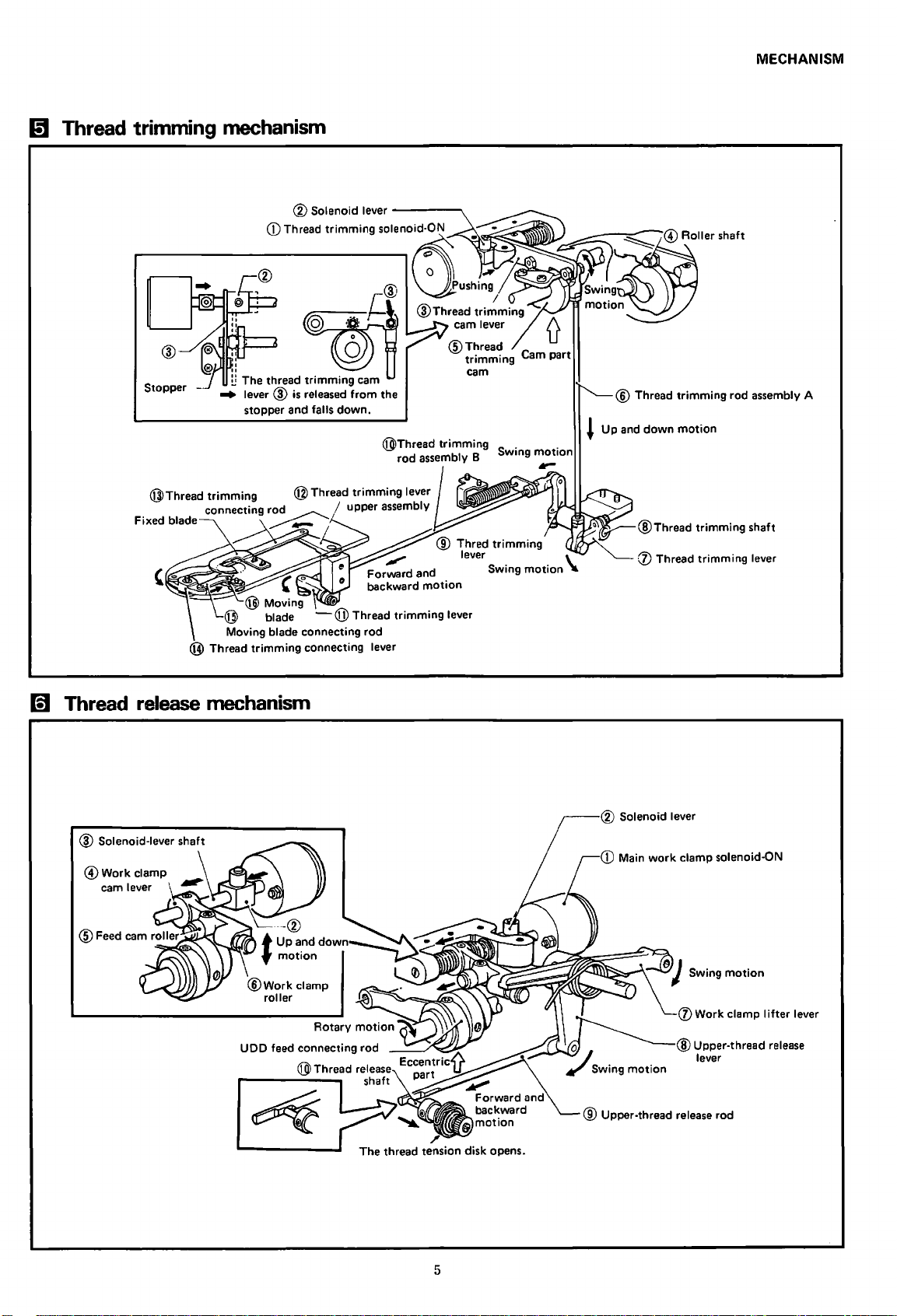
Gt
Thread trimming mechanism
MECHANISM
n
"
Stopper -
Gl
Thread release mechanism
~
~
Moving blade connecting
@ Thread
•
The thread
lever ®
stopper and
is
trimming
~@
0
trimming
released
connecting lever
falls
cam
from
down.
rod
the
@Thread
.tJIIII"""
Forward and
backward
trimming
rod
assembly B Swing
® Thred
lever \
motion
trimming
Swing
motion
motion
~
Up
® Thread
and
down
@Thread
(f) Thread
trimming
motion
trimming
trimming
rod assembly A
shaft
lever
5
CD
Main
work
clamp solenoid-ON
(j)
Work
Upper-thread release
@
lever
clamp I
ifter
lever
Page 8
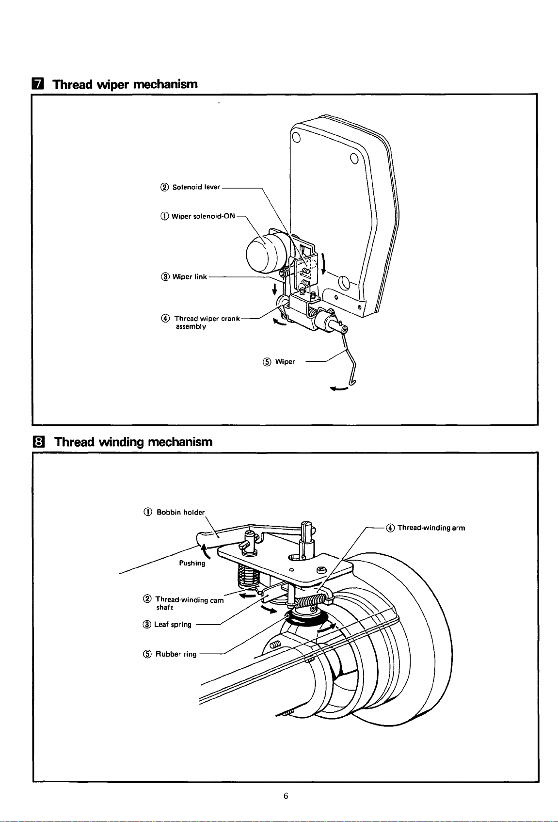
6 Thread wiper mechanism
® Solenoid
CD
@ Thread wiper crank
CJ
Thread winding mechanism
lever----..
Wiper solenoid-ON
assembly
@Wiper
CD
Bobbin holder
® Thread-winding cam
shaft
@ Leaf spring
6
Page 9
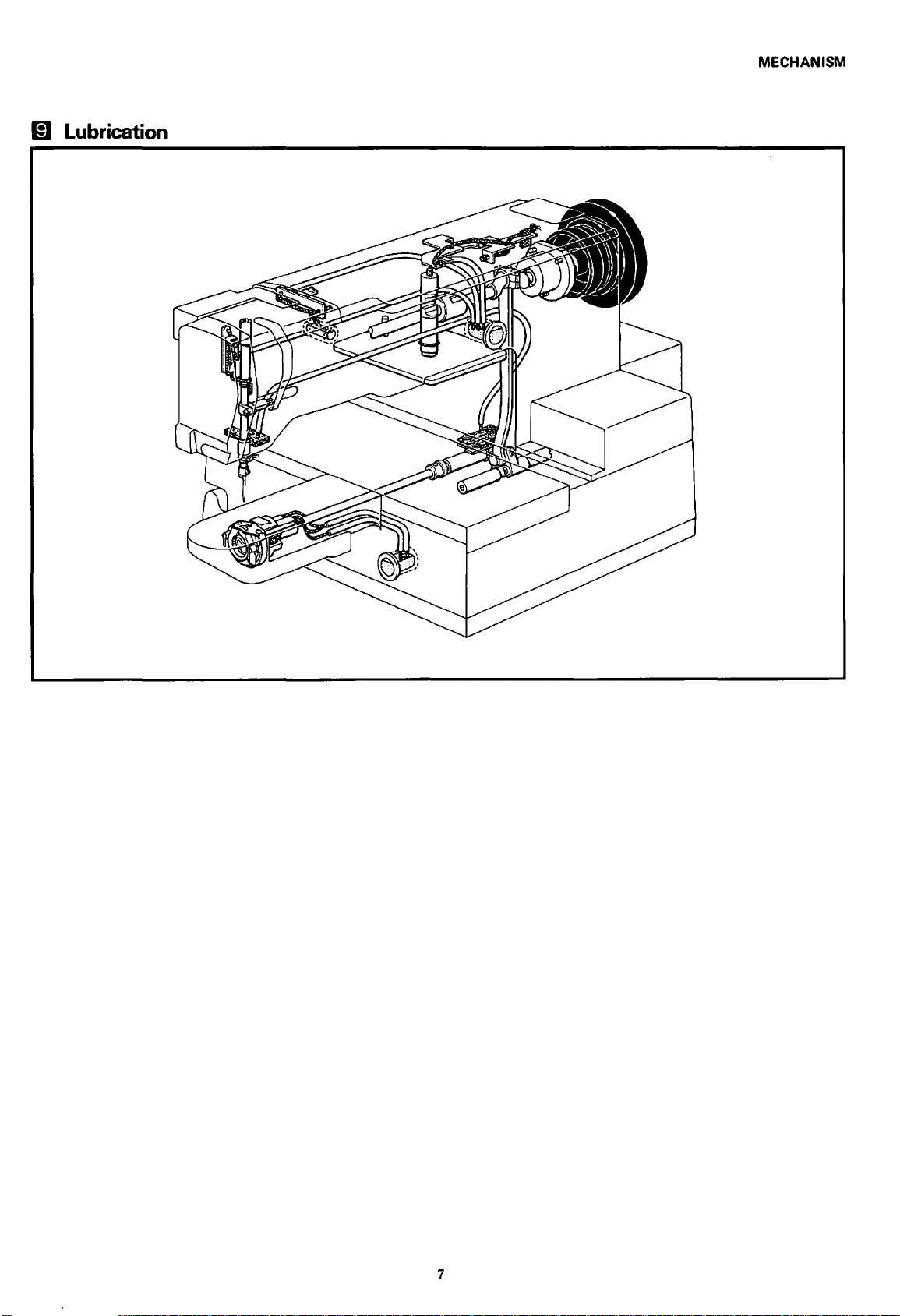
(!] Lubrication
MECHANISM
7
Page 10
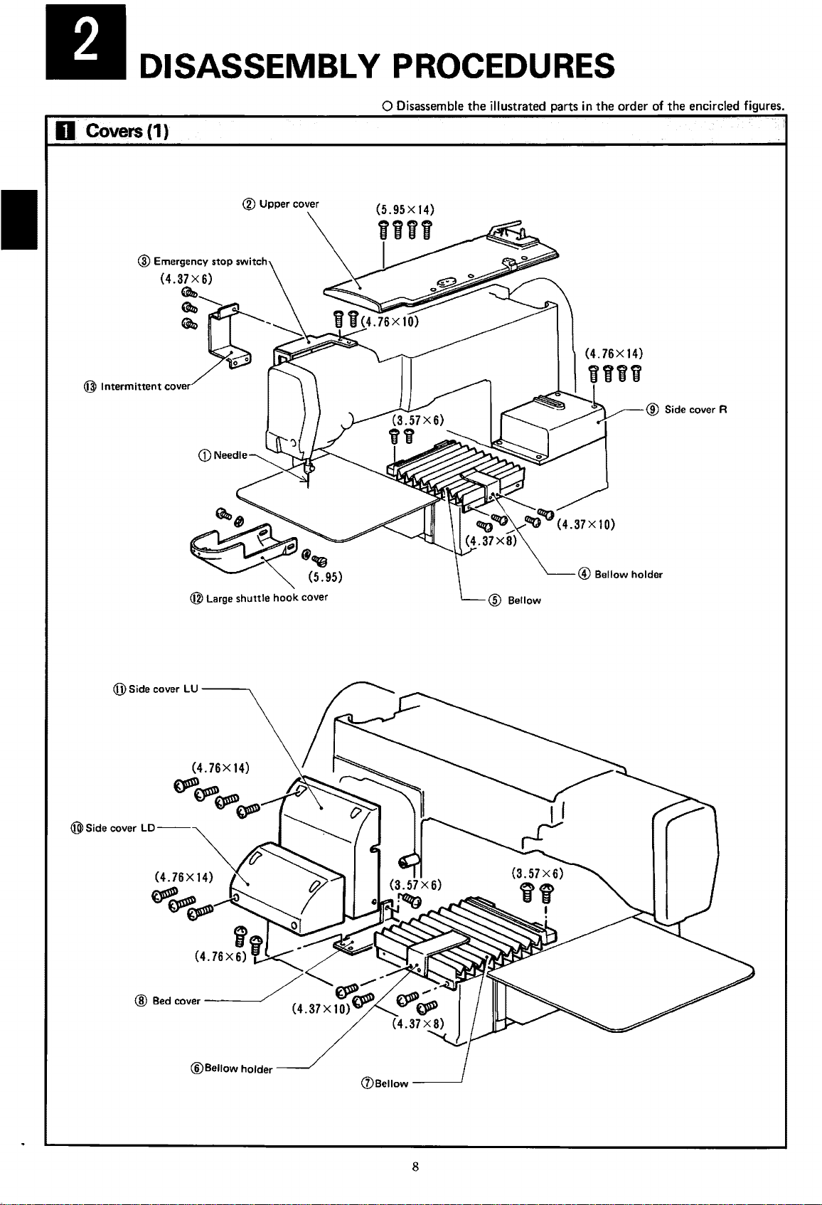
DISASSEMBLY PROCEDURES
D Covers(1)
® Upper cover
0 Disassemble
the
illustrated parts in
the
order of
the
encircled figures.
(jJ)
Side cover LU
® Side cover LD
@ Large shuttle
---...
(4.
76X
~~
~~
14)
hook
cover
@Bellow
holder
Cl)Bellow
-----'
8
Page 11
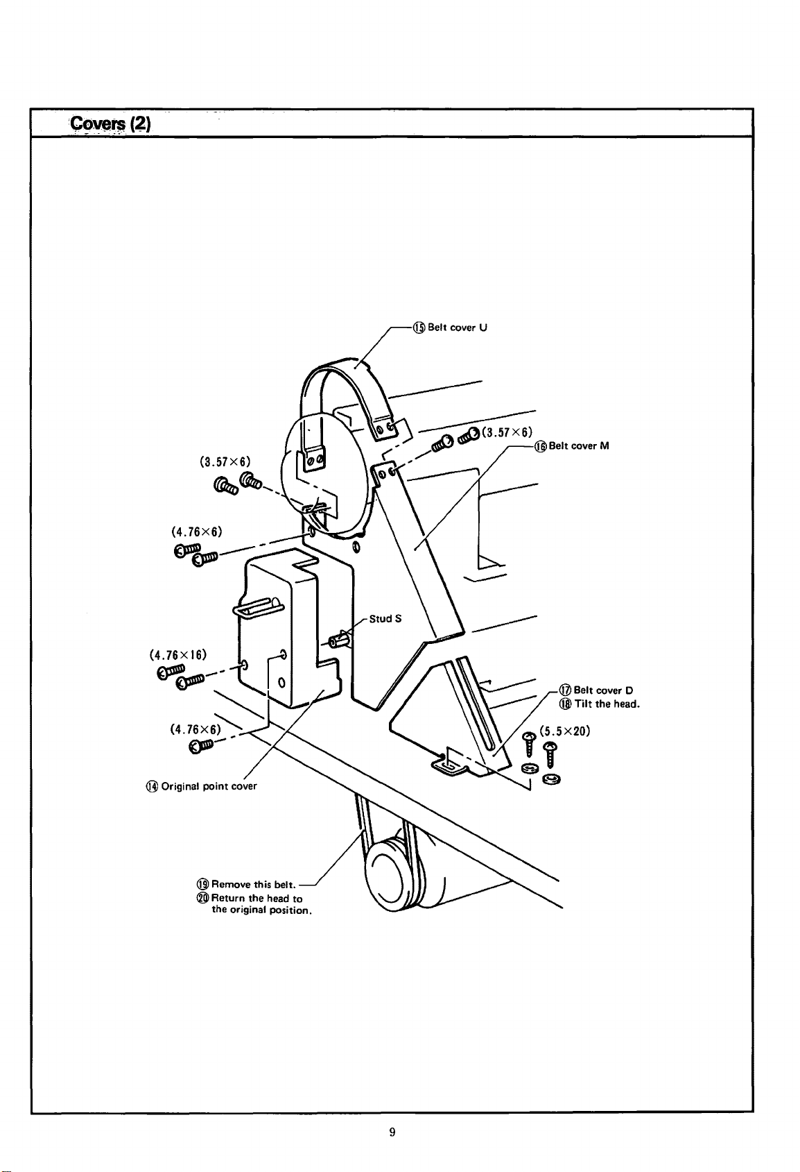
:Cave~(~)
:-·
- -- -
...
-
(3.57X6)
@ Belt cover U
~~'--
(4.76X6)
~~----
@Original
point
cover
@ Remove this belt.
®
Return
the
the original pos1t1on.
hea~
!o
9
Page 12
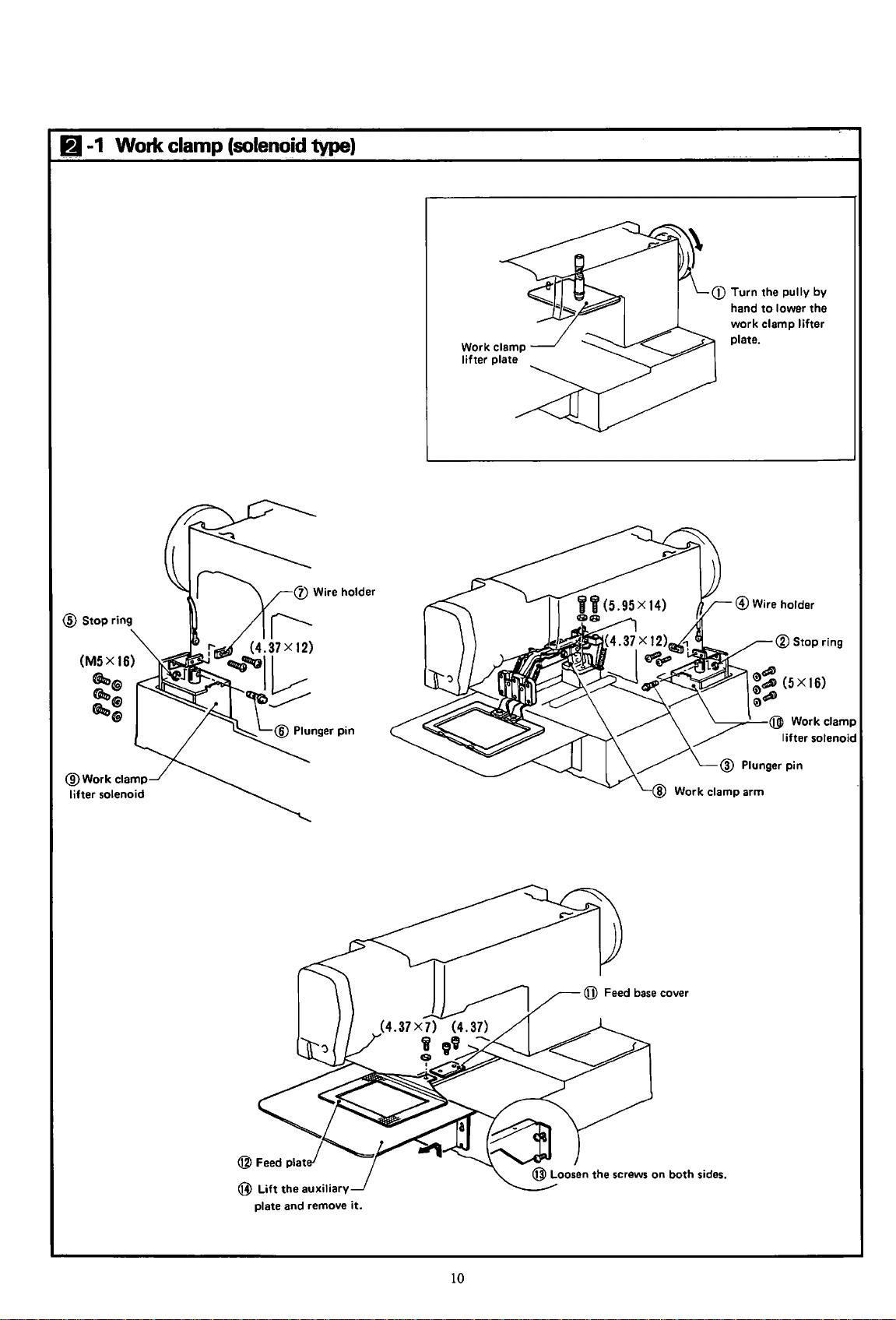
11-1
Work
clamp
(solenoid
type)
Work clamp
lifter
plate
CD
Turn
hand
work
plate.
the
pully
to
lower
clamp
by
the
lifter
@Stop
(M5X
ring
16)
~®
(Az,®
~@
Work
clamp arm
®Stop
'---__,.....-®
lifter
ring
Work clamp
solenoid
@
Lift
the
auxiliary
plate and remove
it.
10
Page 13
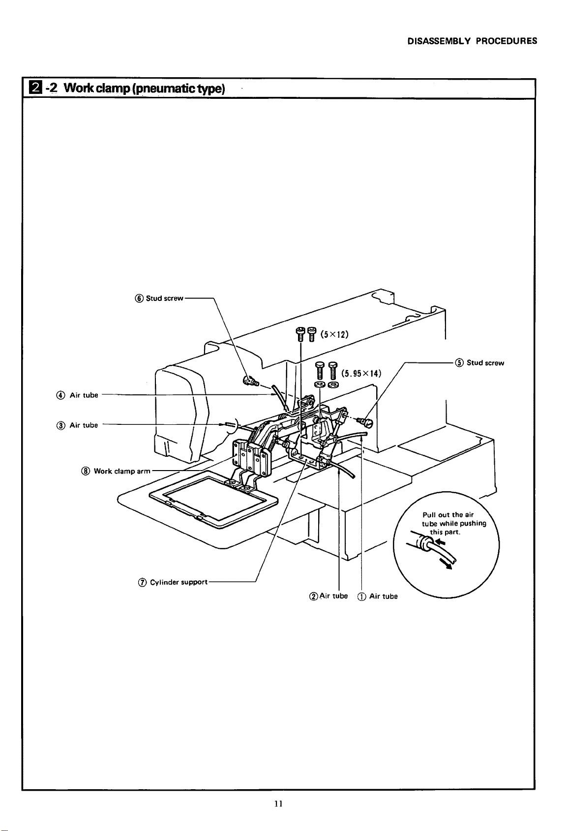
6-2 Workclamp(pneumatictype)
®Stud
screw--""'"'
DISASSEMBL V PROCEDURES
(f) Cylinder
support------J
®Air
tube
CD
Air
,.-----@
Pull
tube
~·
tube
Stud screw
out
the air
while pushing
11
Page 14
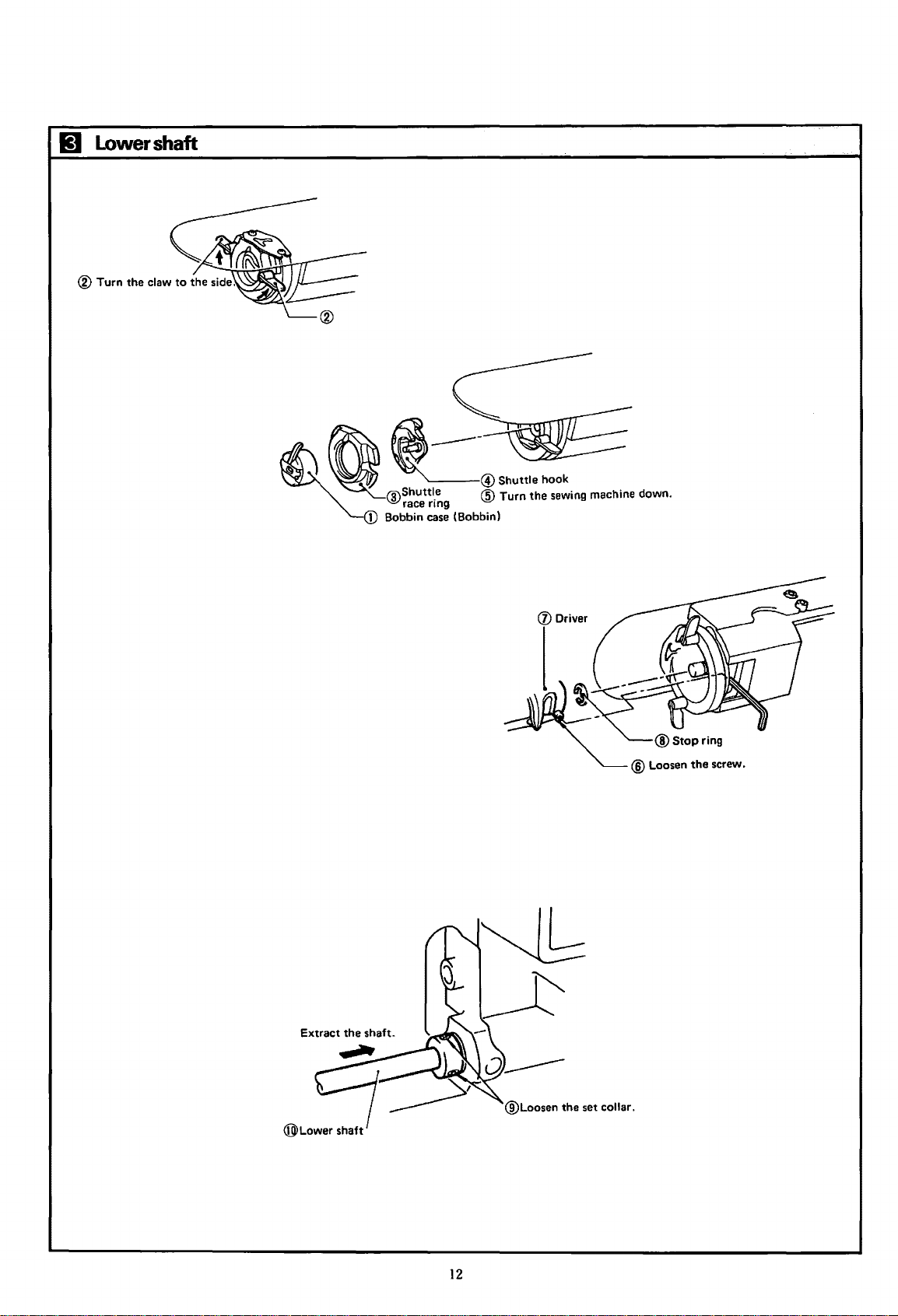
11
Lower
shaft
Extract
the
(j) Driver
shaft.
®Lower
®Loosen
shaft
12
the
set collar.
Page 15
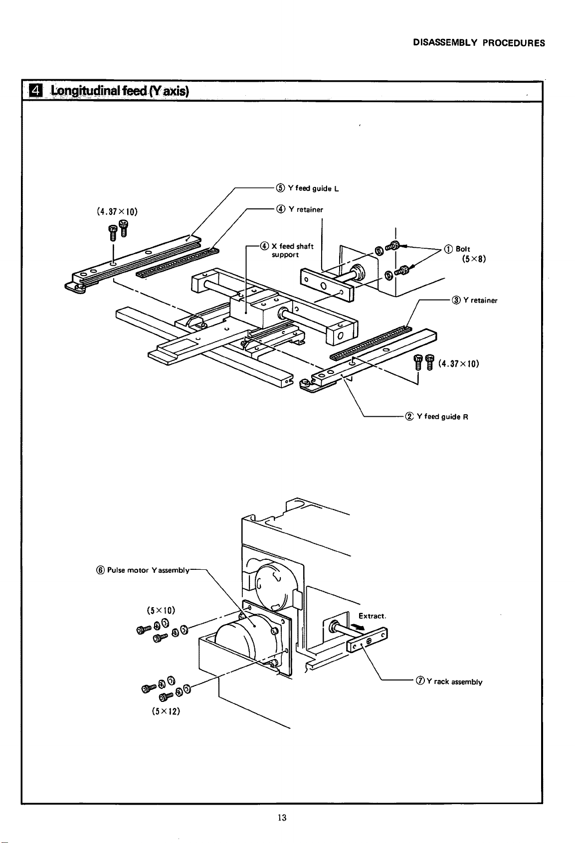
DISASSEMBLY PROCEDURES
,---@
Y feed guide L
®Pulse
motor
Yassembly
13
'---
(J)
Y rack assembly
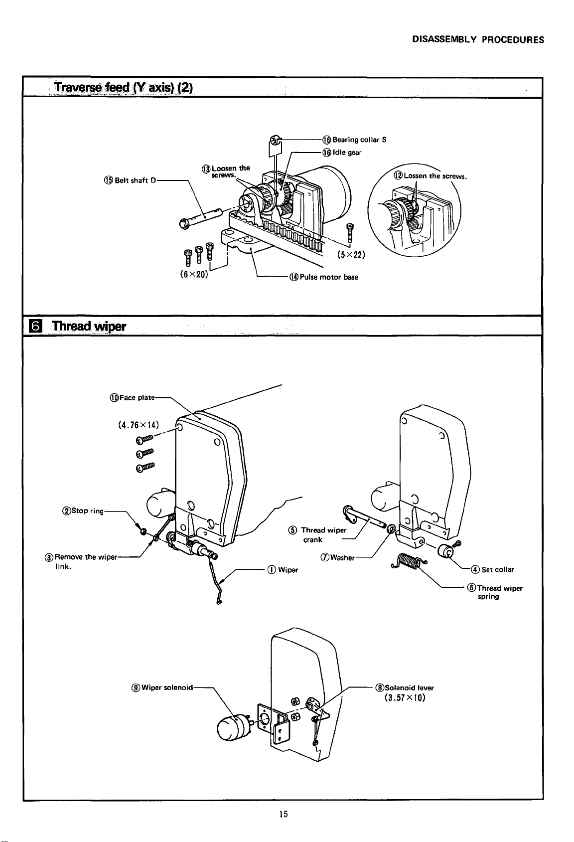
Page 16
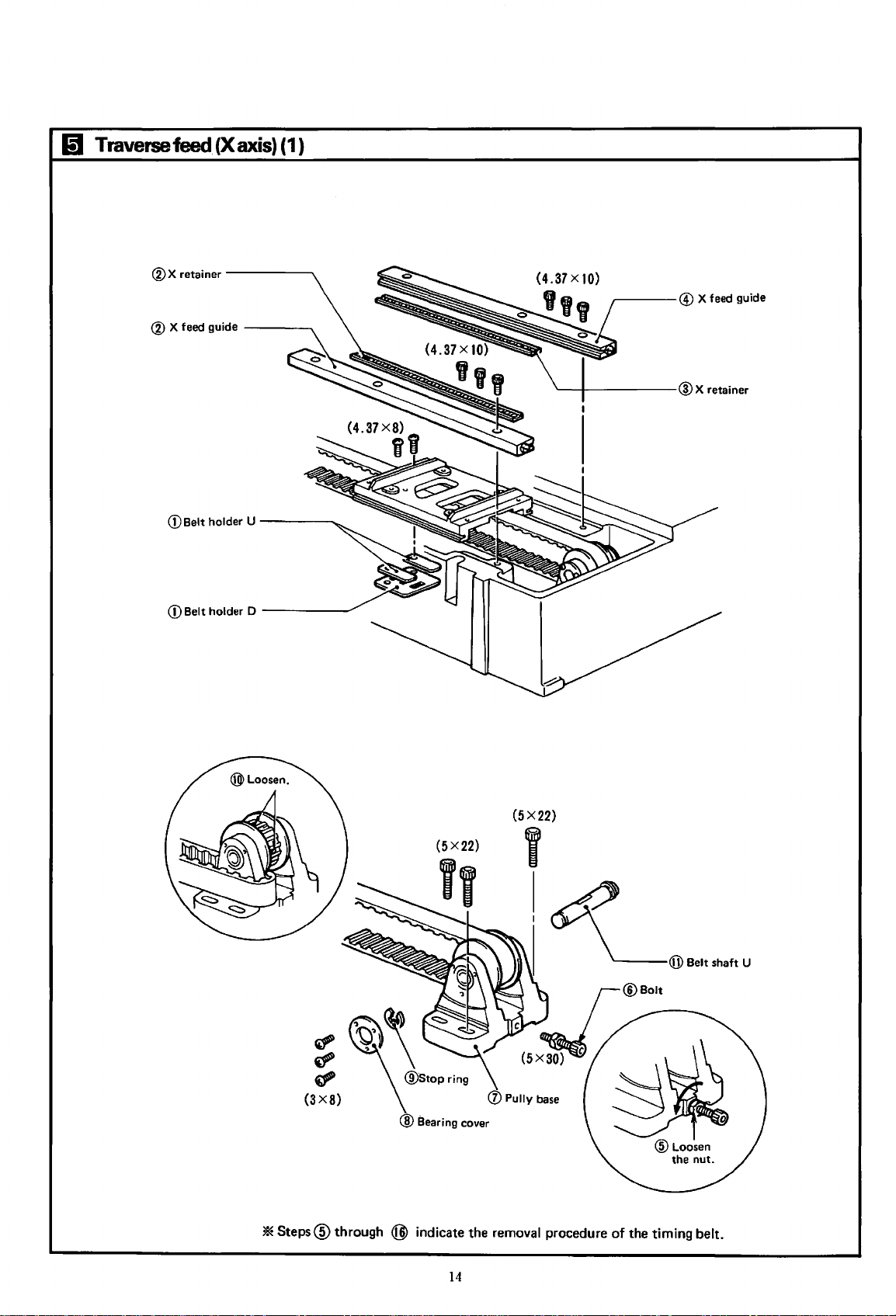
Iii
Traverse
feed (X
®X
retainer----
axis)
(1)
.......
® X feed guide
(DBelt
holder U
CD
Belt holder D
----..
----
------"
(3X8)
'*Steps@
~
d'
d"
through
(5X22)
I
I
(l)
Pully
base
@ Bearing cover
@)
indicate the removal procedure of the timing belt.
14
Page 17
DISASSEMBL V PROCEDURES
@Stop
ring
(4.
76 X 14)
~
~
~
___
,,,
(6X20)l)
..
'
1.......---@Pulse
motor
(5X22)
base
@Remove
link.
the
wiper
@Wiper
~--(])Wiper
solenoid~
15
@Solenoid
(3.57X10)
lever
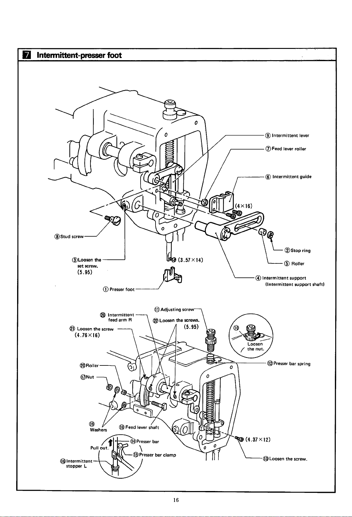
Page 18
6
lntennittent-presser
foot
@Loosen the
set screw.
(5.95)
CD
Presser foot
@Intermittent
~~
L@Roller
fii\
'--
Intermittent support f )
1.!!.1
(Intermittent sup
lever
®stopring
• port sha t
® Loosen the screw
(4.76X16)
@Intermittent
stopper L
@ Intermittent
feed arm R
"(4.37 X 12)
\___@Loosen
the screw.
16
Page 19
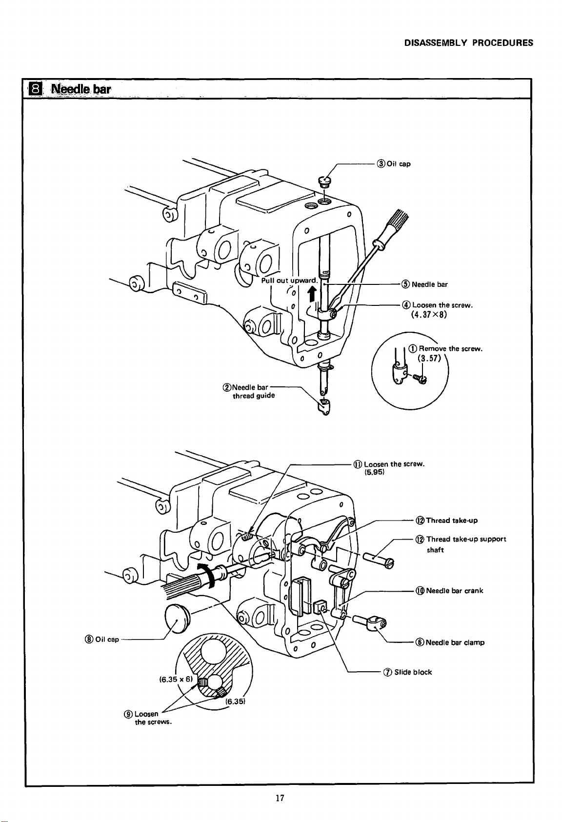
DISASSEMBLy
@Loosen the
(4.37
X8)
screw.
PROCEDURES
@Loosen
the screws.
@Loosen
(5.
) e screw.
95
th
~
®Needle
bar clamp
17
Page 20
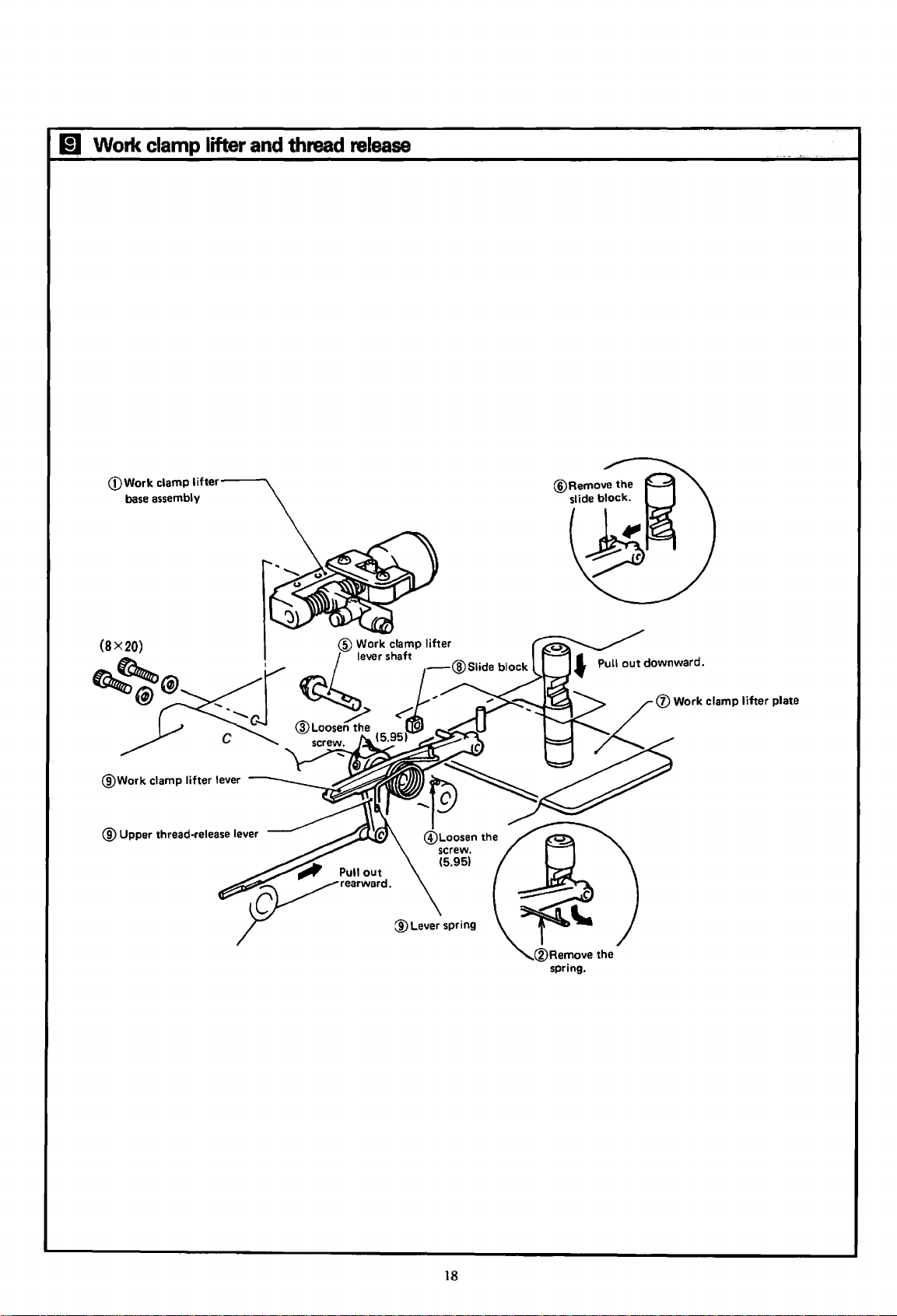
(g
Work
clamp
lifter
and
thread
release
(DWork
@Work
base
clamp
assembly
clamp
lifter
lifter
lever
® Upper thread-release lever
®Remove
spring.
18
the
Page 21
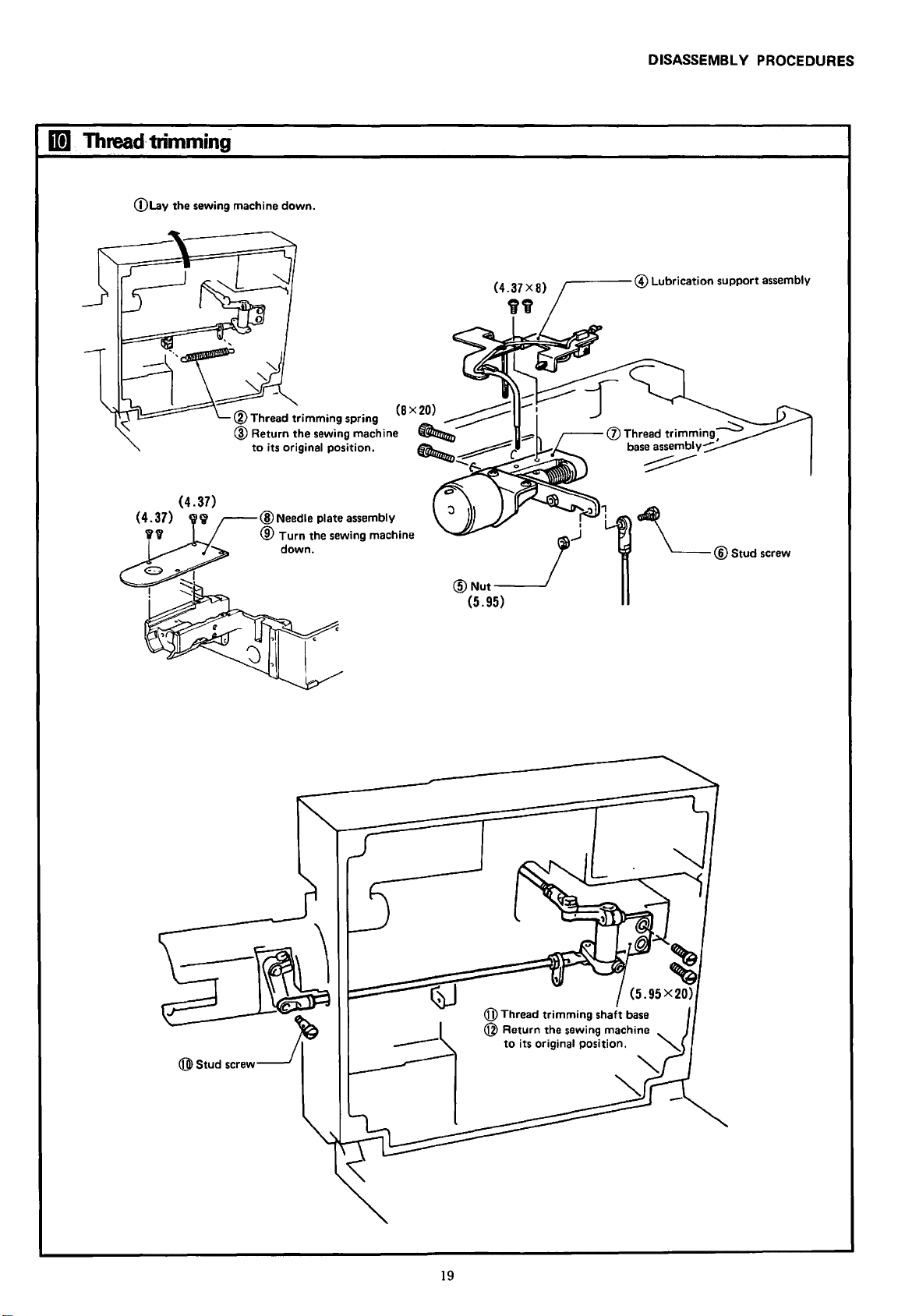
1Dl
Thread·
trimming
(DLay
the sewing machine
DISASSEMBL V PROCEDURES
down.
®Needle
®
Turn
down.
plate assembly
the sewing machine
@Nut__}
(5.95)
r-----@
'f/
Lubrication support assembly
1
1
\__®Stud
screw
@Thread
@ Return the sewing machine
19
trimming
to
its original position.
shaft
"'
base
'-
"-
"
Page 22
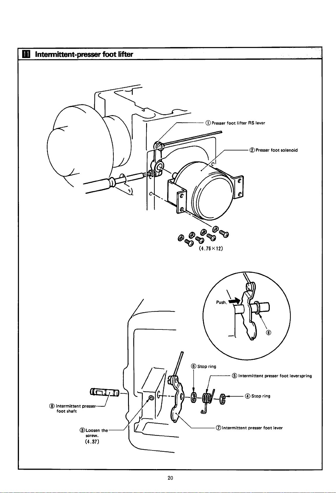
m
lntennittent-presser
foot lifter
~---
®Presser
foot solenoid
-~~
~.:.:~~
(4.
76 X 12)
,..---@Intermittent
®Intermittent
foot shaft
pre~
@Loosen the
screw.
(4.37)
"------(])Intermittent
20
-{1~·---
@Stop
presser foot lever
presser foot leverspring
ring
Page 23
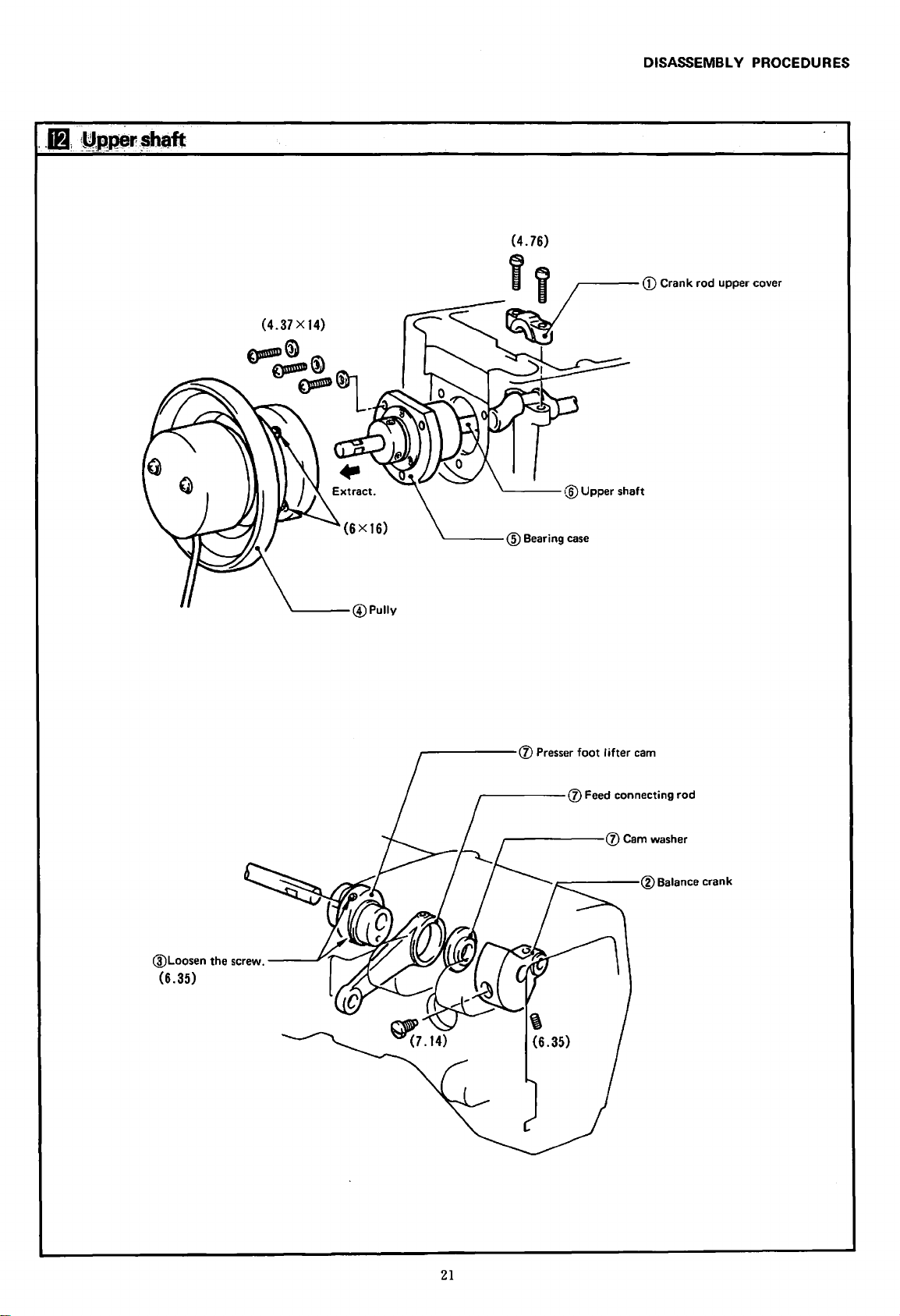
DISASSEMBLY PROCEDURES
@Loosen the
(6.35)
screw.----'
(6X16)
'----@Pully
'------@Bearing
.-----(j)
-----
Presser foot I ifter
------(j)
case
cam
(j) Feed connecting rod
Cam
washer
21
Page 24
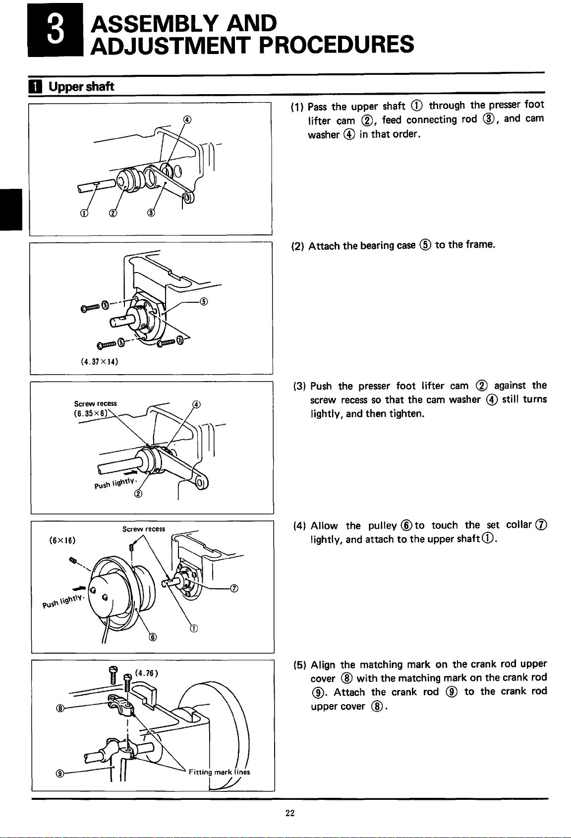
ASSEMBLY
AND
D
Upper
ADJUSTMENT
shaft
PROCEDURES
( 1)
Pass
the upper shaft
lifter
cam
@,
washer@
(2} Attach the bearing
in
that
CD
feed connecting rod
order.
case@
through the
to
the frame.
presser
@,
and
foot
cam
Push
the
(3)
screw
lightly,
(4)
Allow
lightly,
(5) Align the matching mark on the crank rod upper
cover
presser
recess
and
then tighten.
the pulley
and
attach
@with
@. Attach the crank rod @
upper cover
foot
lifter
cam
(g)
against the
so
that
the
cam
washer @ sti
®to
to
the matching mark on the crank rod
@ .
touch the
the upper shaft
to
CD.
the crank rod
set
II
collar
turns
(J)
22
Page 25
@
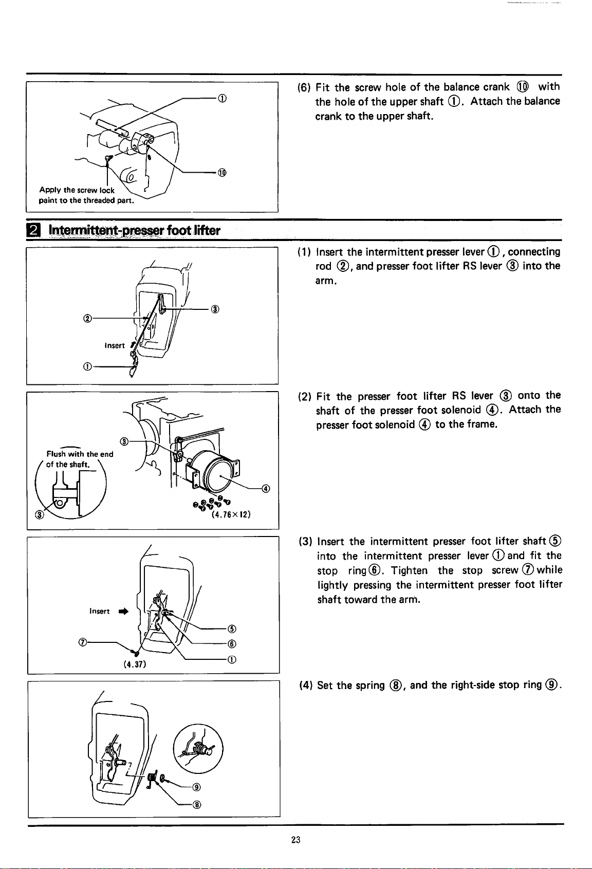
(6)
(1)
Fit
the
the
hole
crank
Insert
rod
arm.
screw hole
of
the
to
the
upper shaft.
the
intermittent presser lever
®,and
presser foot lifter
of
upper shaft
the
balance crank @ with
CD.
Attach
RS
the
CD,
connecting
lever@
balance
into
the
(j)l--
Insert
........
'------®
'-----CD
@
(2) Fit
shaft
presser
(3)
Insert
into
stop
lightly
shaft toward
(4) Set
the
presser
of
the presser
foot
the
the
intermittent presser lever
ring®.
pressing
the
spring@,
foot
lifter
foot
solenoid @
intermittent presser foot lifter
Tighten
the
intermittent presser foot lifter
the
arm.
and
RS
lever @
solenoid
to
the
frame.
the
stop screw (j) while
the
right-side stop
@.
CD
onto
Attach
shaft®
and fit
ring@.
the
the
the
23
Page 26
Bl
Needle
bar
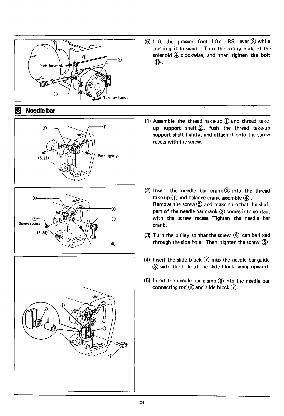
(5)
Lift
pushing
solenoid@
®.
(1)
Assemble
up support
support shaft
recess with
the
presser
it
forward. Turn
clockwise, and then tighten
the
the
foot
lifter
thread take-up
shaft®.
lightly, and attach it
screw.
Push
RS
lever@
the
rotary plate
CD
and thread take-
the
thread take-up
onto
the
the
while
of
the
bolt
screw
Insert
(2)
take-up
Remove
of
part
with
the
crank.
(3) Turn
(4)
the
through
Insert
® with
(5)
Insert
connecting rod
the
needle bar
CD
and balance crank
the
screw@
the
needle bar
screw recess. Tighten
pulley so
the
side hole. Then, tighten
the
slide block (j) into
the
hole
the
needle bar
®and
and make sure
crank@
that
of
the
clamp®
slide block (j).
crank@
the
screw ® can be fixed
slide block facing upward.
into
the
assembly@.
that
comes into
the
needle bar
the
screw ®.
the
needle bar guide
into
the
needfe bar
thread
the
shaft
contact
24
Page 27

ASSEMBL V AND ADJUSTMENT PROCEDURE
DPX5
OPX17
--®
Cutting
part
(6) Insert
(with
toward
(7) Turn
the
the
17). Tighten
(In case of the needle
ence line.)
(8) Fit
bar@.
the
needle
the
oblique
the
operator).
the
pulley so
lowest position. Match
needle bar with
the
needle-bar thread guide @
Attach
@.
(9) Mount
the
oil caps
the
bar@
cut
that
screw
the
@and
from
the
part
of
the
the
needle bar comes
the
reference line
the
second lowest line
of
the
needle bar clamp.
DP
x 5, use
screw@
@on
to
the
top
of
needle
the
on
the
needle bar
frame.
the
top
the
arm
bar@
(DP
refer-
needle
to
of
x
lEI
Intermittent-presser
foot
@
(1) Fit
(2) Insert
(3) Lightly hold
(4) Fit
the
intermittent feed shaft
the
insert
the
@.
Tighten
tent
feed arm R
feed shaft
tighten
the
from
®
(Position
bar@
the
the
guide
groove
the
at
the
toward you.)
intermittent feed arm
CD
screw®.
of
top
same time.
the
(Dto
the
R®.
roller@
the
the
and intermittent feed arm R
part
the
of
screw hole plane part
into
the
feed lever
®at
frame between
of
frame. Insert
the
shaft@
the
center
the
presser bar clamp (j) with
arm, and insert
feed connecting rod
to
of
the
the
the
presser bar @
the
of
frame and
the
intermit-
oval hole.
intermittent
®and
stopper L
the
presser
®
Threaded plane
the presser bar @.
of
25
Page 28

,..----®
(5)
Fit
the
intermittent lever ®
presser bar clamp (j), and tighten
@.
in
the
the
shaft
of
roller shaft
the
r----
Roller
shaft
(6) Attach
(7) Fit
lever
guide
(8) Attach
(9) Try
find a
Tighten
(10)
Fit
(11) Fit
the
the
feed lever
@.
<[4)
the
to
move
point
the
the
roller®
the
intermittent
link@.
roller@
Temporarily secure
to
the
frame.
adjusting
the
where
intermittent
presser
in
the
screw@
there
guide®
roller shaft.
support
.
bar®
is
in
the
intermittent
the
intermittent
up and down and
the
least resistance.
at
this point.
shaft@
in
@ , and fit with the screw recess. Lightly push
the
intermittent
support
shaft
@ and tighten.
the
roller
"'--T-i--@
frJ.JJ~~ef---....;.-i---
(J)
®
(12) Fit
( 13) Remove
the
stop
ring@
the
adjusting screw
presser bar spring
in
@.
again and fix it with
(14) Turn
the
pulley until
lowest position. Loosen
L@.
(15)
Try
to
move
the
link
and find a
tween
clamp (j) and
®
at
ing it
place where
the
bottom
the
stopper L
this point. (Move
at
the
point
indicated by
link L becomes easily movable.)
the
roller shaft. ·
Tighten
the
nut
@.
the
presser bar comes
the
intermittent feed arm
L@
leftward and rightward,
there
surface
of
®.
the
link
@and
the
is
no clearance be-
Tighten
L@
the
insert
adjusting screw
the
presser bar
the
while push-
arrow, and
to
the
the
link
the
26
Page 29

lit
·WGrk
clamp
lifter
aod
thread
ASSEMBLY AND ADJUSTMENT PROCEDURE
release
(1) Assemble the
thread
rod@.
Insert the
(2)
until
shaft@.
(3)
Fit
release
Put the assembly in the arm.
end
it
comes
the lever spring
work
lever®,
clamp
and
of
the upper thread
contact
with
@with
lifter
lever
upper thread
release
the thread
the
boss
of
CD,
upper
release
rod®
release
the frame.
Push lightly.
(4)
Insert the work clamp
lower surface
(5)
Fit
the slide block (j) in the shaft
clamp
(6) Insert the work clamp
with
pushing the
27
lifter
the
plate®.
screw
work
of
the frame.
recess.
clamp
lifter
plate®
lifter
lever shaft @
Tighten the
lifter
lever shaft lightly.
from the
of
the
screw®
work
and
while
fit
Page 30

®
<D
{7)
Raise
the work clamp
lever spring@
(8)
Place
the roller
clamp lifter levereD,
lifter
base@.
0.5 mm between the
and
the
end
of
lifter
plate ®
with
the work clamp lever
of
the
cam
lever®
and
mount the work clamp
Ensure that there
end
of
feed
the work clamp lifter
and
fit
CD.
under the
is
a clearance
roller shaft @
cam
work
@ .
the
of
0.5mm
(9) Turn the pulley until the thread take-up
the lowest position, while pushing the main
clamp solenoid
on the work clamp I ifter
( 1
0)
Push
the thread
upper thread
upper thread
tension disk
@so
release
release
release
loosens.
that the feed roller @
cam
@ .
shaft
rod@,
lever®
®with
and adjust
part ®
until the thread
comes
work
rests
of
using
to
the
the
28
Page 31

ASSEMBLY AND ADJUSTMENT PROCEDURE
(8X20)
~
~®:
®;;:::::::---~-~----CD
0.5mm
®~/])
@~
@
®
(1) Attach
Ensure
the
thread trimming cam @ .
(2) Attach
to
(3)
Lay
(4) Attach
frame.
the
thread trimming base
that
there
end
of
the
roller
the
upper shaft lubrication
the
thread trimming base
the
sewing machine down.
the
thread trimming shaft
is
a clearance
shaft®
of
and
CD.
CD
to
the
0.5
mm between
the
end
support
base@
frame.
of
the
plate@
to
the
(5) Attach
trimming
(6) Attach
trimming cam
@).
the
thread trimming rod B
lever(]).
the
thread trimming rod
lever®,
and tighten with
®to
A®
to
the
the
thread
thread
the
nut
29
Page 32

Return
to
the original
position.
(7) Hook up
(8) Return
the
the
thread trimming
sewing machine
spring@
to
the
.
original position.
16
Traverse
feed
(X
axis)
(9) Attach
thread trimming
trimming connecting
the
(1)
Attach
pulse
the
needle
flat head screw.
the
timing.belt®and
motor
o@.
base
plate@
lever@
CD
by fitting
into hole
rod@ . Start
and
then
the
in
tightening with
timing
attach
pully@to
the
pin
the
belt
on
the
th.read
the
shaft
(2)
Set
the
bearing
at
the
top
of
recess by
them, and then fix with
(3)
Ensure
timing pulley @ are equal. Secure
pulley
recess.
30
that
@with
collarS@
the
belt shaft
lightly holding
the
clearances on both sides
the
screws while adjusting
and idle
D@.
the
the
screws.
gear®
Adjust
belt shaft against
in place
the
the
the
screw
of
the
timing
screw
Page 33

ASSEMBL V AND ADJUSTMENT PROCEDURE
(6X20)
II
~~
I
l.
(6X20)
I
'(5X22)
G9
!
'----CD
(4) Securely attach the pulse-motor
base.
(5)
Attach the timing belt
the pulley
the
reverse
(6) Mount the stop
attach the bearing cover @ .
base
(j). Attach the belt shaft U
side.
ring®
CV
and
on the belt shaft U
base
timing
CD
to
the
pulley®
bed
to
®on
®and
(7)
Ensure
timing
screws pulley ®
recess.
(8) Temporarily tighten the pulley
base.
bolt
tion
CV
applied at the center
base
(9) Fix the adjusting
that the
pulley ®
Adjust the timing belt
@
of
4 mm under a
with
with
the
so
that
3 bolts.
clearances
are
screws
the timing belt produces a deflec-
bolt@
on both
equal. Tighten the timing
while adjusting the screw
CV
load
of
approximately 400 g
of
the belt. Fix the
with
the
base
using
nut@
(j) on the
sides
of
the
bed
the adjusting
pu
I ley
.
Apply
a load
(of
approx.
400
g).
31
Page 34

(1
0) Push
the
X feed
bed base, and tighten.
guide@
against
the
end
of
the
C)
Longitudinal
feed
(V
axis)
,.----@
Attach
(11)
the
( 12) Temporarily tighten
guide
Try
ward while pushing
point
tering and moves smoothly. Fix
this
(13)
Fit
the
and tighten while moving
the X retainer@
X feed guide @ .
the
@
to
the
feed table X ® using
to
move
the
feed table X rightward and left-
the
where
point
the
belt holder D @ . Load 2 belt holders U ®
using
teeth
the
feed table X @ causes no chat-
the
bolts.
of
the
timing belt into
and feed table
X retainer
X feed
the
feed table
@and
guide@.
the
the
X@
X feed
the
bolts.
Find a
feed table
groove
X@.
to
at
of
CD
32
(
1)
(2)
Put
the
original
Attach
raising it
Y rack
point
the
CD
into
dog ® with it parallel
pulse-motor Y @
lightly so
that
the
frame. Insert
to
the
its backlash becomes 0.
the
to
the
axis.
frame while
Y
Page 35

ASSEMBL V AND ADJUSTMENT PROCEDURE
Push lightly for
adjustment.
®
(3) Push
(4) Attach
(5) Attach
(6) Tighten
the
Y feed guide L @ against
feed table X ®, and tighten.
theY
retainer®
the
Y retainer @ and Y feed guide R @
and move
push
where
and moves smoothly, using
the
feed table X ®
theY
feed
guideR®,
the
feed table Y (f) causes no chattering
the
Y rack
@.
and feed table
the
Q)to
the
the
end
of
the
v(f).
to
the
left. Lightly
and tighten
bolts.
X feed shaft support
at
a point
BJ,
Lower
@------..
shaft
and
relevant
(1) Lay
(2) Put
(3) Engage
(4) Mount
(5) Fit
(6) Return
the
sewing machine down.
the
lower shaft
rear side, and fit it
collar®
and tighten
does
rarily tighten it through
not
the
the
facing
the
lower shaft
the
chatter.
stop
driver@
the
sewing machine
CD
to
the
the
bushing side.
set
collar®
ring@
with
in
the
machine from
ground surface
gear®
on
the
the
with
so
that
the
lower shaft
lower shaft
stop
ring@.
to
its original position.
of
the
swing gear,
the
lower shaft
CD.
the
CD
Tempo-
the
set
33
Page 36

1Dl
Work clamp arm and
~levant
Tightening screws
• For electromagnetic types (For pneumatic types,
(1) Attach
tighten while matching
auxiliary plate with
plate®.
(2) Tighten
(3) Attach
@.
start
from item (10).)
(4) Attach
®
to
the
auxiliary plate
the
the
feed plate @
the
feed table
the
work clamp lifter solenoids R
the
frame.
CD
the
upper surface
to
the
cover@
to
the
frame, and
upper surface
of
the
feed table
to
the
feed table Y
CD
of
needle
Y@.
and L
the
,---@
r---(1)
@--
(J)
(5) Remove the presser
® (6) Fit
(7)
@
(8) Put
--
the
work clamp
feed table
Attach the presser
clamp lifter
Y@
the
plunger pin (j)
wire®,
®.
springs@
arm@
and secure.
springs@
and hold it with
at
.
into
again.
the
the
top
groove
of
the
the
stop ring
in
the
work
34
Page 37

ASSEMBLY AND ADJUSTMENT PROCEDURE
• For pneumatic types
(9) Hold the
®
with
(10)
Fit
the work clamp
feed
table
tip
of
the wire
Y@,
the work clamp
presser
and
V ® ,
arm@
secure.
into the groove in the
and
lifter
tighten.
wire fitting
(11) Attach the cylinder
®.
(12) Attach the cylinder
arm lever C
( 13) Connect the air tube
the left.
@ .
support@
joint
as
illustrated in the Figure to
to the
@to
the work clamp
feed
table Y
Viewed
from
the lower rear side
of
the
machine table
35
Page 38

m
Thread
wiper
Face
plate-----r-1..._11_
r-----<D
<D
(1) Attach the wiper solenoid
CD
to
®.
(2) Temporarily tighten the solenoid
wiper
solenoid
(3)
Attach the thread wiper
spring@,
and
CD.
set
collar
CD
as
crank@,
illustrated.
the solenoid
lever®
to
washer@,
base
the
(4) Lightly
screw
the thread wiper crank.
(5) Hook the
(6)
Fit
wiper
(7) Temporarily tighten the thread wiper
thread wiper
(8) Attach the
push
is
aligned
spring®
the wiper
crank@,
face
the thread wiper
with
the
screw
on
the
screw.
link®
and
crank@.
plate
with
mount the stop
(jJ)
.
crank@
recess,
the pin
on
ring®.
until the
and
tighten
the thread
®to
the
~-®
36
Page 39

ASSEMBLY AND ADJUSTMENT PROCEDURE
(9) Attach the
(10) Adjust
thread wiper
where
(
11)
Turn the pulley
19
mm away from the upper surface
plate.
(
12)
Adjust by putting the thread wiper @ in
until there
needle
needle@.
using
it
stops.
and
threed
the solenoid
@
becomes
so
that
is
clearance
wiper®.
lever
horizontal at the point
needle
of 2 mm
®
so
tip
is
positioned
of
the
between the
that the
needle
and
out
Tip
of
the
shuttle
~@
~
hook
DPX17
(13) Turn the pulley by
lowest position. Align the reference line
needle
(In the
highest reference line.)
Insert the shuttle
(14)
the
at the center
bar
case
driver®
with
of
until the
of
hand
until the
the lowest reference line
the
the
needle
hook@
needle.
tip
DP x 5,
into
of
the shuttle hook
needle
use
the arm. Adjust
(DP
the
is
at the
of
x 17).
second
rests
the
(15) Attach the shuttle
set
the claw. Put the bobbin case@ in the shuttle
hook@.
37
race
ring@
to
the arm,
and
Page 40

1m
Intermittent-presser
foot
(1)
Remove
the
oil cap
CD
on
the
face plate.
(2) Turn
(3) Loosen
(4)
(5) Fit
the
position.
Turn
the
position.
the
align with
porarily tighten
pulley until
the
screw on
pulley until
presser
the
top
the
foot@
end
the
presser foot.
the
needle
presser bar
the
needle
in
the presser
of
the
screw
is
at
the lowest
clamp®.
is
at
the
bar@
head@.
highest
and
Tem-
(6)
Turn
the
pulley until
lowest position
the center of
(7) Press lightly
the needle hole plate, and tighten
presser bar
(8) Attach the oil cap (D.
(9) Attach
foot®.
at
while ensuring the needle rests
the
the
clamp®.
the center of the groove of
hole
top
in
of
the
the
the
needle bar rests
presser foot.
presser
foot@
the
screw on the
the
at
the
at
against
presser
38
Page 41

ASSEMBLY AND ADJUSTMENT PROCEDURE
CD-----...
~·
4.37X8
( 1 ) Attach the upper cover
(2)
Attach the bellows R ®
table rightward
to
the
feed
(3)
Attach the bellow holder R
and
table@.
leftward while tightening them
CD.
and
®and
L@.
Move
L@.
the
feed
(4) Attach the
(5)
Attach the
side
cover R (j).
side
cover
LU@.
39
Page 42

(6) Attach the
side
cover
LD@.
(7) Attach the
(8) Mount the emergency stop
(9) Attach the intermittent
(10) Attach the
using the
bed
large
wave
cover®.
shuttle hook
washer @
switch@.
cover@
cover@
and
stud screw ® .
.
to
the
arm
(11) Lay the
return the sewing machine
(12) Attach the belt cover M
40
sewing
machine down.
to
its original position.
®.
Fit
the V-belt
and
Page 43

ASSEMBLY AND ADJUSTMENT PROCEDURE
{3.57X6)
fi,(j,
®,-----,.
(13) Attach the belt cover
( 14) Attach
.the
belt cover D @ with two
U@.
washers.
(15) Attach the original point
cover@.
screws
and
41
Page 44

STANDARD ADJUSTMENTS
g,
Adjustmen~
of
n•le~bar
heigflt
(1)
Remove
the oil
cap
CD.
DPX5
Lowest position
11
Matching the needle with the tip
~---
~--
Needle bar
Needle bar bushing
Needle bar bushing
of
(2) Turn the pully until the
lowest position.
(3)
Loosen
(4)
Align the
lower
DP
x 17). (For a
reference line).
the shuttle hook
(1)
Turn the pulley
lowest position
with the lower
a
DP x 17
second
the
screw®.
second
end
of
needle). (For a
highest reference I i
lowest reference line with the
the
needle
DP
to
raise
and
align the lowest reference line
end
of
needle
bar bushing (the
x 5
needle,
the
the
needle
DP
ne.)
bar
use
needle
bar bushing (for
x 5
needle,
rests
at the
needle
the highest
bar from the
use
of
the
Tip
of
the
shuttle
hook
DPX17
Center
of
needle
(2)
Loosen
®so
the center
the
set
that the
of
the
screw
tip
of
needle.
CD
and
adjust
the shuttle hook
using
the driver
aligns
with
42
Page 45

Tip
of
the shuttle
hook
Center
of
needle
(1) Turn the pulley
hook
to
align
with
to
allow the
the center
tip
of
the needle.
of
the shuttle
E1
Adjustment
Tip
of
the shuttle
of
Center
the
of
needle
I
i
hook
needle
Tip
of
receiver
the shuttle
hook
of
the
(2) Adjust by loosening the
eccentric shaft
the needle
0.01 mm
to
®so
and
the
0.08 mm.
driver
(1) Align the
the
needle
tip
of
the shuttle hook
by
turning the pulley.
screw
CD
and
turning the
that the clearance between
tip
of
the shuttle hook
with
is
the center
from
of
(2) Lay the
(3)
Loosen the
tric
needle
43
sewing
shaft @
receiver
machine down.
screw®.
so
that the
of
the driver
Adjust by turning the
needle
lightly contacts the
CD
.
eccen-
Page 46

(1)
(2)
(3)
Remove
Loosen
Raise
it
the
the
the auxiliary
toward the operator.
feed
plate
screws®
<D.
.
plate@
and
remove
by
sliding
(4)
Remove
(5) Drive the
guide@
Allow
tighten.
the
the
needle
needle
into both
needle
plate®.
groove
to
of
the shuttle hook thread
sides
of
the
needle
lightly touch the bottom
center.
and
44
Page 47

DJ
A,~jJJ$tm,ent
of
tb!3
_wort<
c.laRJp
STANDARD ADJUSTMENTS
lift
(1) Loosen the
@until
work clamp
the arm, when the work clamp lifter plate
<To
set the work clamp
( 1 ) Loosen the
that there
clamp lifter plate
left) when the holder
nut®
there
lifter
screws
is
a clearance
and
adjust the adjusting screw
is
a clearance
plate
CD
and
lift
to
a maximum
@ (right and left)
of
1 mm between the
CD
and
lever
is
lowered.
of
2 mm between the
the lower surface
plate®
is
of
20
and
adjust
(right and
of
raised.
mm:>
so
work
fJ
Adj~stment
of the moving blade
5-6mm
@
(2)
If
the clearance
(3) Loosen the
solenoid
part
(1) Set the
(2) Loosen the screw
trimming connecting lever
groove
CD
side
becomes 5 to
sewing_machine
edge
is
even
is
screws@
until the wire
®
with
the
greater, the
and
6 mm.
in the stop position.
®
and
of
the shuttle hook thread guide
tip
of
lift
is
reduced.
pull the wire tube on the
of
the
presser
adjust using the thread
@
so
the moving
that
the needle
blade®.
arm
lever
45
Page 48

• Replacement
of
the
moving and fixed blades
( 1 ) Remove
the
feed plate
CD
.
(2) Loosen
(3) Raise
(4) Remove
(5) Remove
the
it toward
the
new one.
the
screws®.
auxiliary
the
the
needle
the
plate®
operator.
plate@.
moving
and remove by sliding
blade@
and replace it with
~@
®
~
Do
notpro!QJ@
leftward
from
here.
(6) Remove
new one. Ensure
between
fixed blade
the
leftward from
(7)
Reassemble
ing
46
the
the
tip
of
the
disassembly steps.
fixed
blade®
that
needle hole plate (j) and
®after
the
fixed blade ® does
the
end
the
moving and fixed blades
and replace it with the·
there
is
a clearance
replacement. Make sure
of
the
needle-hole plate (j).
not
of
1
mm
the
new
that
protrude
by
revers-
Page 49

STANDARD ADJUSTMENTS
(1)
Turn the pulley until the presser foot
lowest position.
(2)
Loosen the screw
the
where
lightly contacts the material
(3)
Turn the pulley and make sure
enters
(4)
If
the
presser foot, remove
screw@,
lower surface
the
center of the presser foot.
needle does not enter the center of
and turn
<D.
Retighten it
the
the
presser
of
the presser
to
be sewn:
oil
cap@,
bar@
at
that
to
is
at the
a position
foot®
the
needle
the
loosen
adjust.
the
I]
Adjustment
of
the intermittent-presser foQt
Standard lilt 3.5mm
L~~:ta
®
CD
lift
o The standard I ift
~
t
<To
change the standard lift:>
1)
Loosen the nut
(
the
feed connecting
\lncrea~
S Decrease
lowering the set position decreases
(2)
Remove the face
of
the presser foot
<D.
Raising the set position
rod®
plate@.
is
increases the lift;
the
3.5 mm.
of
lift.
47
Page 50

(3) Turn
the
position. Loosen
pulley until
the
the
presser bar
intermittent feed arm L
is
at
its lowest
@.
1m
Adjustment
--,~~------.'-#---@
'------®
of
the
tbread
wiper
(j)
(4) Ensure that there
bar clamp
bar
kept touching
Tighten
(
1)
Adjust
® so
stop position.
(j) I intermittent
bushing@,
the
the
intermittent feed arm L
the
thread wiper
that
the
is
no clearance among
stopper®
with
the
intermittent
intermittent stopper
CD
with
the
wiper becomes horizontal
the
I and presser
support@
support@.
@.
solenoid lever
presser
at
the
e.:-_;:::-·
\
.\
·~
@____)'-
<D
<D
2mm
®
(2) Actuate
wiper with
of
CD
thread wiper does
At
the
approximately 2 mm from
48
the
the
approximately 2
and the tip
the
same time, ensure
front the tip
thread wiper
screw@
mm
of
the needle. Make sure
not
of
the
CD.
so
that
between
strike
the
that
thread wiper
the
center
Adjust
there
presser
when viewed from
the
is
a clearance
the
thread wiper
foot@.
CD
protrudes
of
the
thread
that
the
needle.
Page 51

m
Adjustment
of the
needle-$top
position
an_~:-~
tifTiing:
STANDARD ADJUSTMENTS
. i
Needle
19mm
top
position
Material
Needle stop
position
raises.
Direction
of
rotation
(1) Remove
(2) Adjust
®so
mm
plate.
stop position; counterclockwise,
the
cover
the
needle-stop position with
that
the
away from
Turning
CD
of
needle tip comes
the
upper surface
the
element®
the
synchronizer.
lowers it.
the
element
to
a stop 19
of
clockwise raises
the
......
20
needle
Needle
_[I
top
position
LBF
Direction
of
rotation
..
...
stop position
lowers.
eeong
d.
No
feed
(3)
Adjust
element @ so
needle has come
and stops before
Note: For thicker material, increasing
timing speed reduces
sewing performance.
the
timing
that
of
the needle and feed with
feed starts working after
out
of
the
material being sewn
the
needle touches
needle flow and improves
the
the
the
material.
the
feed
~atch
The element ® coincides
with
the
magnet@
take-up
thread
tion.
top
at
posi·
the
49
Page 52

J$
Adjustment
of
the original point
(1) Remove the feed plate
(2)
Attach
original
the original -
point
is
in
the center on the operator side.
point
CD
.
reference plate
®.
The
Q)-------
Orig
inal point
(X-O·Y.Q
)
<
Adjustment
(1) Remove
(2) Remove the bellow L ® .
(3) Switch
(4)
Press
(5) Move the
reference plate
(6) Loosen
aligned
by
moving the X original
and
<
Adjustment
(1) Remove the
(2) Switch the sewing machine ON.
(3)
Press
(4) Move
reference plate
(5) Loosen
point
needle
of
X axis>
the bellow
the
sewing machine
the
[E] key on the programmer.
needle
th
e screws ®
with
the original point.
leftward.
of
Y axis>
original-
the [E) key on the programmer.
the
needle
the hexagonal
dog ® forward and backward
tip
aligns
holder LG).
tip
by
turning
point
tip
by
turning
with
the
ON.
toward
the
so
that
point
cover
toward
the
bolt
® . Move
original
the
pulley.
the needle
Adjust
dog @ rightward
eD.
the
pulley.
point
original-point
tip
is
the X axis
original-
the
.
point
original-
until
the
50
Page 53

Tension gauge
Approx.
~mm
e:-
420g
±11
r----®
(3)
Loosen
with
(4)
Ensure
imately 4 mm
imately
STANDARD ADJUSTMENTS
the
nut @ and
the adjusting screw @ .
that the timing belt
at
420
g.
screw@.
the center under a load
Make adjustment
is
deflected
by
of
approxapprox-
Ill
.
Adjustment
<D---
of
the
upper
thread
release
timing
(
1)
Remove
(2) Turn the pulley while pushing the main
clamp solenoid
the
take-up@
with
upper thread
the upper cover
®.
work
clamp
the upper thread
lifter
at the lowest position. Then, adjust
loosens.
Place
cam@
~
CD.
the
feed
release
cam
and
keep the thread
lever®
roller
until the
work
@on
51
Page 54

lEI
Adjustment
of
.the
,backlash
<Lower
(1)
(2) Loosen
shaft>
Lay
the
®
to
0.07 mm
sewing machine down.
the
screw
CD
and turn
adjust
at
the
backlash. Provide a play of
the
top
of
the
the
driver®.
swing gear shaft
0.04-
l.
(5X10) fiP
<Longitudinal
(1)
Loosen the bolts
motor
between the drive gear and theY-rack shaft.
..
~.~:""'llii.,_
Lift
it
up
slightly.
---®
<Traverse feed>
(
1)
Loosen the bolts
motor
between
52
feed>
CD
and slightly raise
® . Adjust so
X®.
Adjust so
the
drive gear ® and the idle gear
that
no backlash remains
CD
and slightly raise the pulse-
that
there
the
is
no backlash
@.
pulse-
Page 55

STANDARD ADJUSTMENTS
lm.~
Adjqstmeqt
Qf
0.5mm
1he
(])~
®---¥
ml
~djt~.~ent
of
the.
thread
work
c_lamp·
..
trirnming,t:aro
CD
lifter
ba~
(
1)
Adjust with the thread trimming
there
shaft
CD
is a clearance
and
the thread trimming
of
0.5
P9'ition
(1) Attach the work clamp lifter
ing
that there
work clamp lifter
@.
is a clearance
cam
®and
cam
mm
between the roller
cam®.
base
CD
while
of
0.5
mm
between the
feed
cam
roller shaft
11
®until
ensur-
53
Page 56

HOW
TO MAKE UP THE PRESSER
e The presser
The
maximum
• Clamping
Type
~
How
to
is
available in
sewing
Work
clamp
two
range
types; clamping
is
100 ( L) x 120
Work
(Single
clamp
type)
type
and cassette type.
(W)
mm.
v~l
Feed plate
make up the clamping type presser
• Cassette
Cl
amp
1.
How
Type
spring~
~
~
to
make up
the
:7
~""
work
-
Cassette clamp
·
~
Cassette cl
clamp blank
<OpPOrt
amp
assembly
Presser
Feed
foot
plate
-----
D/2 +
1-1
.5
D/2
mm
~-
+ 1-1.5
Work
,--
Feed plate
Work
Sewing
clamp
(One-piece
(The
threads along.)
clamp
position
needle
mm
type)
2.
Cut
out the
si
ze
is
presser
D:
How
wor
wider
than a sewing
foot
diameter + 1-1.5 mm
Diameter
to
make up
k clamp blank
of
the
top
end
the
feed plate blank
posit
of
so
that
the
ion
by
(half
).
the presser
cutout
of
the
foot
Cut
out
the feed plate blank 1-1.5
ng
the
case
I
I
I
I
I
I
I
I
L
l...
_-_-_-_-_-_-_-l
~
1-1.5
1-1.5
Sewing
position
mm
mm
the sewi
In
required on
54
position.
of
the
both sid
mm
left
figure, 1-1.5 mm margin
es
of
the
sewing position.
apart
from
is
Page 57

Work
clamp
(Standard) \
OT
clamp
asse mbly
3. How
(
1)
(2) Bond a
to
make
Cut
out
contour
around
material
up
the
the
of
a material
paper
the
cut-out
to
be
plastic presser
plastic pla
to
cushion
part
sewn.
te
according
be
sewn.
material
to
secure ly press a
or
to
the
the
like
fl
How
Feed plate blan k
to
make up the cassette type presser
~
Hin
g e
s
Cassette pl
ate
U
(3) Make
*
Th
e cassette
plate
in
the left
(1)
item
U,
Cut
up
"2.
cassette
figure.
out
the
ting dimensions, refer
make
up
the
* Making up
nately
w
the
feed
plate
How
to
make
type
presser
plate
D,
cassette plates U
clamping
two
cassettes
blank
upthefeedplateblank."
is
composed
and
to
type
by
hinges as illustrated
and
section
presser."
to
use them al
ill increase work efficiency.
referring
of
a cassette
D.
For
"1.
How
to
cut-
to
ter
-
Cassette
\_
clamp
assembly
Cassette
Casse
Lower cassette plate (Plastic plat
tte
plat
plate
e D-A
D-B
(I
ron)
(2) Bond a
aro
material
*
The
cassette
und
paper
the
to
be
plate
cushion
cut-out
part
sewn.
D is available
material
to
or
secure ly press a
in
two
the
like
types; D-A
and D-B.
* Use
the
cassette
the
D-A,
except
must
be
bonded
mounting
a
counters
eter
hinges
countersunk
plastic plate.
unk
plate
that
on
on
screw
hole
D-B
a plastic
the
back
the
cassette
M3 into
prior
with
of
the
plate
the D-B.
plate
the
4.6
to
Co
unt
same
way as
or
the
D-B, insert
mm
bonding
ersunk
screw M3
like
When
diam
the
-
I
~
e)
Lower cassette plate
Bond
55
Page 58

I
Work
clamp
Work clamp blank B·1R
Work chimp blank 8·1 L
Work clamp blank B·3R
Work clamp blank
blank
BolL
I
t3.2
t4
153448-000
153449-000
153470-000
153471-000
DDI·
50+--1
Work clamp blank 1·3R
Work clump blank 1-3L
Work clamp blank 1-4R
Work clamp blank 1-4L
Work clamp blank 1-5R
Work damp blank 1·5L 502826-000
t3.2
t4
t5
502821-000
502822-000
502823-000
502824-000
502825-000
Work clamp blank 2·3R
Work chimp blank
Work clamp blank 2-4R
Work clamp blank
~ork
clamp blank 2·5R
Work clamp blank
2·3L
2-4L
2·5L
t3.2
t4
t5
502827-000
502828-000
502829-000
502830-000
502831-000
502832-000
Work clamp blank 3·3
Work clamp blank 3-4
Work clamp blank 3·5
Back
T
11
....__
___
1--150~
I
Feed
plate
___,
1
blank
Feed
plate blank 1
Work clamp blank 5·3
W~rk
Work clamp blank 5-5
clamp blank 5-4
Work clomp blank 4·3
Work clamp blank 4-4
Work
clamp blank 4·5
r~
l 1
1--170--j
Feed
plate blank 2
Feed
plate blank 3
T
156
I
Feed
plate blank 4
56
I
Feed
plate blank 5
Page 59

Cassette clamp j
Cassette clamp 1 A
Cassette clamp 1 L
[ni
106
Cassette clamp
Cassette
I Clamp spring I
clamp
2R
2L
70-11
82--1
crr·~
10
10-t
1
82~
Cassette clamp
Cassette
clamp
3R
3 L
Cassette clamp
Cassette clamp
Cassette support
assembly(t3.2)
502963-001
Lower cassette plate
A(t1)
502969-000
B (
t2)
502970-000
4R
4L
236~
~\&,
~
t0.4
I Clamp spring 1 I 502853-00 I I I Clamp spring
OTclamp
assembly A
(t0.5)
t2)
503902-001
503904-001
8 ( t 1 ) 503903-001
c (
~~
Cassette plate U-A ( t
-152632-001
1)
B(t2)
Hinge, right
502968-000
502971-000
t 0.6
21
502854-00 I I I Clamp spring 3 I 502855-00 I l
~~~~~~amp
Cossette plate U·A
Hinge, left
Hinge, right
Cassette plate D·A
t 0.8
A
502959-001
502968-000
152633-001
152632-001
502966-001
Cassette plate D-A(t1)
502966-001
I Presser
foot
I
Presser foot L
502469-001
Presser foot R
502441-001
57
~::'~~,,!=lamp
Cassette plate U·B
Hinge, left
Hinge, rigtlt
cassette
B
plate D·A
Presser foot
505667-001
502960-001
502971-000
152633-001
152632-001
502966-001
MM
Page 60

D
Description
ADJUSTMENT
OF
ELECTRIC APPLIANCES
on
fuse
1. Position
Open
the front.
the control box cover.
of
fuse
Control
box
At
the upper left
---f---
is
the
fuse
holder
having
three
fuses,
when viewed from
2. Fuse capacity
No.
1
2
3
I
i
. ®
I®~®
~®~&
&A
~
(4X10)
Type and capacity
Cylindrical fuse:
Glass
tube fuse:
Glass
tube fuse:
of
fuses
5A-500V
15A-125V
15A-125V
For AC
For pulse
For
and brake
input
pulse
Remarks
motor
motor, solenoid,
of
sewing machine
and
motor
clutch
58
Page 61

3. Countermeasures when a fuse blows
For
your
reference, the following table shows phenomena when a fuse blows.
the
same
capacity
as
that
of
the blown
one.
Be
sure
to
use
a fuse
with
Fuse No.
0
No power lamp lights
o The low
o
The
o No presser opens
o
The
of
presser
low
motor.
torque
torque
measurement
6
1
2
3
Voltage
The following figures show where
1. Check
Measure
for
control voltage +5V, + 12V and
voltage
with
a tester· between check pins on the PCB;
CH4
CH3
CH2
0 0 0 0
-12V
+12V ±OV
Trouble encountered when a fuse blows
or
works.
of
pulse
motor
causes the distorted
is
easily moved by hand even when
or
closes.
of
pulse
motor
causes feed malfunction only with noisy sound
to
measure
voltage on the
-12V
CH
1
+5V
the
PCB
or
dislocated patterns.
motor
is
energized.
and
connectors.
CH
1-CH2,
CH2-CH4
Reference page
and
CH2-CH3.
78 (#2)
80 (#7)
79 (#5)
Check list 1
SV
DC±
C H I
C
H4EB-
C H
ffi-
2EB-
C H
C H
C H
28
28
38
12V
59
0.25V, acceptable
DC±
O.SV,
acceptable
Page 62

2. Check
( 1 )
for
drive voltages
Remove
VL
and
the connector P 1 .
VH
I]·
On
(2)
Note:
lffi-38
2®-38
...
LEOs.
the
Measure
wire
side
Use
on
:PCB
PCB
are
drive voltages
of
the connector
a tester probe
Check list 2
Approximately
Approximately 1
eight LED lamps by which the operator
VL
on
and
P1
using a tester.
the
side
44 V DC,
OV
DC, acceptable
VH
on the
of
the lead.
acceptable
lead
can
D
monitor
(Viewed
control
7 6
8 9
from
signals.
3 2 1
5 4
13
In
11
12
10
-
the lead wire side)
1.
Monitoring solenoid
The
LE
Ds
noid
is
turned ON.
LED 1:
LED 2:
LED3:
LED4:
LED 5: Left
output
1 through 6 light when
Right
side
of
presser
Presser
Thread wiper
Main
foot
presser
side
of
presser
o
o o
oD
oD
each
iU
·oooo
sole-
0
CJ
2.
000000
Monitoring
LED 7
LED 8 for brake:
LED7
LEOS
output
for
clutch:
Lights while the
rotating.
Lights momentarily when the sewing
machine
panied by a braking sound.
of
brakes and clutches
sewing
comes
to
a stop, accom-
machine
is
LED6:
Thread trimming
60
Page 63

El
How
1.
Changing
movement
to
use
the
DIP sWitch
selectors 1 through 3
of
the
presser.
of
DIP switch
CD
located on the lower
Turn
the power
then open the
off
and
control
ADJUSTMENT
left
box.
OF
of
the control
ELECTRIC APPLIANCES
PCB
varies
the
The presser
OFF
ON
:~
is
automatically raised after sewing.
····································
OFF
:1
Raise
the presser by pressing the work clamp lifter pedal
after sewing.
Pressing the work
presser@,
ously.
To lower them, turn the switches
low. (The work clamp lifter
stage switch.)
1st stage switch
2nd stage switch 0
1st stage switch
2nd stage switch
clamp lifter pedal ® raises the right
left
presser@,
ON
-the
N-
the right presser @ and presser
foot
ON
-the
ON-
the left presser @ and presser
foot
ON
n
and presser
pedal®
left
presser@
@ lower.
right
@ lower.
foot@
is
presser@
ON
designed
lowers.
simultane-
as
shown
lowers.
be-
as a 2-
1st stage switch
2nd stage switch
61
ON
ON
-the
-the
right presser @ and left pres-
ser@
lower.
presser foot @lowers.
Page 64

2. Selector 4
of
DIP switch
CD
is
used for selecting
the
electromagnetic
type
or
pneumatic type.
3.
Selectors 5 through 8
The
sewing machine
(the thread trimming speed).
The sewing machine turns within a speed range
1500
spm.
OFF
~~
For electromagnetic
of
DIP
OFF
;
7
8
OFF
;
7
8
ON
~;i~i~i~i~i~i
=~=~=~=~=~=~
~=~=~=~=~=~=
turns
at
ON
~==~=~=~{:
·~=r=~=~=~=
=~=~=~=~=~==
:::::~:~::::
type
switch
CD
approximately
serve
as
230
of
the
spm
550-
test
switch for
The sewing machine turns within a speed range of
1200
volume
The
2000
For pneumatic type
the
sewing machine motor.
OFF
:
~;i~i~i~i~i~~
7
8
spm. The speed may be changed
on
the
panel.
OFF
5
6
7
·1
8
sewing machine turns within a speed range
spm.
ON
ON
~=~=~=~:::::
=~=~=~=~::::
with
the
ON
t=~=~=~=i
:f~=~=~=~
r~
:i:~:i:i:i:
of
400--
speed
850-
Selectors 5 through 8 are provided solely for testing
OFF when
the
sewing machine
is
in
normal use.
the
sewing machine controls.
Be
sure
to
set
all
of
them
62
Page 65

II
Deseriptian
Most
of
the sewing machine failures
faulty contact. Check
contact
with
of
,each
each
wire before troubleshooting. For
connector
to
make
resulting from connector failures.
*For
the connector No., refer
to
are
due
to
connector problems
sure
that
each
connector
your
is
properly inserted
reference, the following table
the control circuit block diagram
ADJUSTMENT
such
as
on
page
OF
ELECTRIC APPLIANCES
improperly inserted connectors
and
each
pin
comes
shows
in proper
the symptoms
70.
and
Connector No.
p 1
J 1
P2
J 2
I
J
27
P27
P3
J 3
I
J
28
P28
P4
J 4
I
J
29
P29
Connection
Power
supply
t
PCB
PCB
t
Each
solenoid
PCB
t
X pulse
motor
PCB
t
Y pulse
motor
signal
Main
+ 5
V, + 12V,
Drive
voltage
Solenoid drive power
supply
Pulse-motor
supply
Pulse-motor
supply
+44
+
-12V
V
y
10
drive power
drive power
Phenomenon resulting
Abnormal motion
o
o No motion
o
Malfunction
wiper parts, main
ming parts.
o Disorder in X direction.
Abnormal sound
o
o Disorder in Y direction.
o
Abnormal noise
from
of
presser,
presser,
from
from Y pulse
improper contact
presser
X pulse-motor.
and
foot,
thread
motor
thread
trim-
P5
J 5
I
J
30
P30
P6
J 6
I
J
21
P21
P7
J 7
P8
J 8
I
J
25
P25
PCB
t
Brakes and clutches
PCB
t
Synchronizer
PCB
t
Switch panel
PCB
t
Programmer
Sewing
and
machine starting
stopping currents
+5V
Needle
top
position,
synchronizing, and rotation
signals
+5V
Speed
volume signal
Key switch signal
Display signal
o Abnormal rotation
o Poor stop
o The sewing machine turns at high
stops. (The emergency stop lamp lights.)
o The mechanism does
needle
o The sewing machine turns
mechanism
o The power
o
Even
the sewing machine
stant
o Malfunction
of
top
position.
does
lamp
though the
speed
of
of
sewing machine
sewing machine
not
not
work.
does
not
light.
speed
volume
keeps
2000
spm.
of
programmer
speed
stop
above
but
turning at a con-
and
the
the feed
is
turned,
63
Page 66

Connector No.
Connection Main
signal
Phenomenon resulting from improper
contact
P9
J 9
I
J
26
P26
P10
J
10
I
J
24
P24
Pll
Jll
I
J
23
P23
p
12
J
12
I
J
22
P22
PCB
FMC device
PCB
Original
PCB
Emergency
PCB
Pedal switch
...
I
..
t
point
t
stop
t
PCB
switch
Read and write signals.
microdisk
X and Y original-point
signals
o Emergency
signal
o LED
o
Start
o Work
stop
switch
signal
signal
clamp lifter signal
of
o
The
microdisk will
o Switches for data, step-back, and tests will
not
function.
o
The
original
o An emergency
o
The
emergency
is
not
released.
o
The
work
clamp I ifter and
not
work
when their pedals are pressed.
point
stop
stop
not
is
is
read.
not
not
lamp
detected.
initiated.
is
turned
start
switches will
ON
but
64
Page 67

1.
Connection of connectors
ADJUSTMENT
OF
ELECTRIC APPLIANCES
The rear face
of
the control box:
2. Fan motor
The fan
tronic
clogged.
motor
parts may
J21
J22:
J23:
J24:
J25:
J26:
J27:
J28:
J29:
cools the inside
be
damaged. Regularly clean the fan equipment
of
Synchronizer connector
:
Foot-switch connector
Emergency stop connector
Original
Programmer connector
FMC device connector
Solenoid connector
X pulse
Y pulse
Clutch
J30:
point
signal connector
motor
connector
motor
connector
and
brake connector
the control box. Make
sure
that the fan
so
that
the air inlet
is
working:
if
does
not, the
not
become
elec-
65
Page 68

TROUBLESHOOTING LIST
Trouble
Inadequate work Improperly posi-
clamp lift
Malfunction
thread wiper
Improper quantity
of
wound lower
thread
of
1--r--
tioned lever plate
Improperly posi-
'--
tioned work clamp
lifter plate
Interference between
the thread wiper and
--
the
Improperly posi-
'--
tioned thread wiper
Improperly posi-
I--
tioned bobbin holder
Cause
needle
Check
Distance between the
upper surface
1-
needle plate and the
work
Clearance between Adjust clearance
1-
the
work clamp lifter
plate and arm
Clearance between
f--.--
the
thread wiper and
needle
Sewing machine
-
position
,-
Thread wiper position
Quantity
f---
thread
clamp
tip
of
of
the
stop
wound
Adjust
1-
clamp height.
1-
2 mm with
ing screw.
Adjust height
1-
thread wiper.
Adjust
(19-20
1-
needle and the upper face
of
the needle plate)
Adjust
r---
where
starts working.
Adjust
-
the
Remedy
the
work
to
the
adjust- 45
of
the
the stop position.
mm
above the
the
position
the
thread wiper
the
position
bobbin holder.
I
I I
L
of
v
.............
45
48
49
48
J
Thread escape
Upper thread break
in
the
hook,
cut
needle
is
too
needle.
of
the
needle
Variations
~
thread length
Excess upper thread
.--
tension
Improperly mounted
f--
needle
The
f--
'--
f--
-
-
thread
thick for
Improper strength
and height
thread take-up spring spring
Flaws and burrs on the
shuttle
hole plate, needle, etc.
Thermal
1---
Sub-tension
I-
Upper thread tension.
Direction
I--
needle
~
Thread and needle
Strength and height
~
of
the
thread take-up
~
Flaws and burrs
I--
Thread end
of
the
Adjust sub-tension.
r--
Adjust upper thread
~
tension.
Mount
1-
~
1-
I--
~
the
the
longitudinal
groove toward operator.
Select a thread
proper size so
match
the
Adjust
the
and height
thread take-up spring.
Polish faulty parts
or
replace.
Use
liquid (silicone)
cooling equipment.
needle with
of
the
it
will
needle.
strength
of
the
I/
v
v
v
v
v
v
66
Page 69

Trouble
Lower thread break
Excess lower-thread
,..--
tension
1-
Flaws
'--
the
needle hole plate
and bobbin case
Cause
on
the
edge
of
1---
Lower-thread tension
1--
Flaws
Check
Adjust
1---
tension.
Polish faulty parts
t---
replace.
Remedy
lower thread
v
or
IV
Lower thread cut.
skip
Stitch
Improper
t---
when
sioner
Excessive clearance
between the needle and
the
Improper
the
shuttle
Driver overloaded
~-L
by the
f--
Bent needle
Improperly
...._
needle
timing
the
main ten-
is
released released
shuttle
hook
contact
needle with
hook
needle
tip
of
the
mounted
Timing when
-
upper thread
Clearance between
the needle and
shuttle
Lift
of
Contact
Clearance
1---
the
driver and the
needle
1----
Bent needle
Direction
1--
needle
the
is
hook
tip
needle bar
between
of
the
Adjust timing when
t---
the
upper thread
released.
Adjust
between
and
shuttle
Adjust
height.
Adjust
(position
shuttle driver).
Adjust the
1---
contact
1---
Replace the needle.
Mount
,___
the
longitudinal groove
toward operator.
the
clearance
the
needle
hook
the
needle bar
contact
of
the
needle
on
the
the
needle with
is
tip.
driver.
51
43
42
42
43
v
v
Needle break
The needle interferes
.----
with
the
hook.
f--
The needle
-
The needle moves
-
sidewise.
The
-
needle strikes
the
moving blade.
shuttle
is
bent.
Clearance between
~
the
needle and
shuttle
1-
Lift
'---
f...--
f...--
-
of
bar
Bent needle
Timing between
needle and feed
Position
moving blade
hook
the
of
tip
needle
the
t---
1---
- Replace
the
1---
~
clearance
Adjust
tween
the
shuttle
Adjust needle bar
height.
Adjust
of
synchronizer feed
detecting part.
Adjust
of
the
needle and
hook
tip.
the
needle.
the
position
the
position
moving blade.
be-
43
42
IV
49
45
67
Page 70

Trouble
Cause
Check
Remedy
The
is
not
upper
cut.
thread
Dull fixed blade
-
Insufficient
blade
-
..._
motion
weak thread
spring pressure
The moving blade
will
not
thread.
-
The moving blade
not
catch upper thread
f--
because
skips.
Improperly posi-
f--
tioned moving blade
Improper timing
..._
when
the
tensioner
moving-
due
to
trimming
catch upper
will
the
final stitch
main
is
released
-
Fixed-blade edge
Thread trimming
-
spring pressure
Position
r-
shuttle
thread guide
of
hook
the
- blade
-
f---
-
Direction
'--
of
Skipping
f--- f---
final stitch
Position
f---
moving blade
Timing for releasing
-
the
of
the
upper thread
seams
final stitch
of
the
of
the
f---
f---
f---
Sharpen
a new one.
Replace
trimming spring with
a stranger one,
Adjust
the
thread guide.
Adjust so
stitch ends
proper seam direction.
Refer
"stitch
Adjust
the
Adjust
timing for
upper thread.
the
fixed
or
replace with
the
thread
B.
the
position
shuttle
hook
that
the
in
the
to
the
item,
skip."
the
position
moving blade.
the
release
the
of
of
/
/
44
/
67
45
51
·Poorly
thread
tightened
Excessively weak
r--
upper-thread tension
Excessively weak
-
-
lower-thread tension
Improper strength
'--
and height
thread take-up spring
of
the
Upper
-
-
f---
thread
Lower-thread tension
Strength and height .
of
the
thread
spring
tension
take-up
Adjust upper-thread
r---
tension.
Adjust lower-thread
f---
tension.
Adjust strength and
f---
height
take-up spring.
of
the
/
/
thread
/
68
Page 71

SPARE PARTS LIST
Item
Needle
Needle hole plate
Shuttle
Shuttle
hook
race
ring
Thin
ol!!
Ci)
Needle
Needle
Needle
Needle
Needle
Needle
Needle
Needle hole plate
(C/>1.6
for
Needle hole plate
((/}2.2
for
material)
Shuttle
~
Shuttle
and medium-thick material
16
19
107415-009
107415-011
107415-016
107415-018
107415-019
107415-021
S02371-001
S02373-001
152685-001
152682-001
DPX5
DPX5
DPX5
DPX5
DPX5
DPX5
DPX5
thin
medium-thick
hook
race
# 9
#11
#14 107415-014
#
#18
#
#21
A
material)
F
A
ring A
Thicker
Needle
Needle
Needle D P X17
Needle
Needle
Needle
Needle
Needle hole plate E
(C/>2.6
material)
D P X17 #
D P X17
D P X17
D P X17
D P X17
D P X17
for
extremely
~
Shuttle
Shuttle
hook
race
material
14
#
16
#18
#19
#21
#24
#25
thick
145646-014
145646-016
145646-018
145646-019
145646-021
145646-024
145646-025
S02372-001
v
B
ring B 152686-001
152687-001
0
Thread take-up spring
Thread take-up spring
Thread tension spring
Caution: Needle and needle-hole plate must
•
Thread tension spring
~
be
properly selected
145519-001
104525-001
to
match the thread and material
Thread take-up spring B
Thread tension spring
to
be
144588-001
107606-001
sewn.
69
Page 72

..
------------------------------------------------------------------------------------------------------------------------------------------------------------------------------------------------
1
, I I I
1
!Ground
Power
source
-
;~g~
>
<>-
"'
uo
....
..J>
><>
J21
P21
Synchronizer
•
•
••
•
•
--~--~.........
"(
p~~~~l
;:~=::~
'•
Control
PCB
::~
~
•
....
--
os~ooa
bUbbUU
CUWCUCIUI)
:S
oo:S:S:S
uuuuuu
~88008
------r
I
:::::!:~~:5::;;E~i~~~~
H3
I ,
lll=tw'!"•&::....:J:
0
:
ff!dj
.....
..,i
Clamp
0
f'-
.c:.--
''l
eader
Card
..
I
JJ
PHil
[o
"'I
Ln
~
•
..!l
...A.lJ
~
;;
'--~--
.
''IJ .
L
__
{FIVI
r
C)
est
tap
ata
ast
ata
ower
am~
bac
lamp:
lamp
j
1
I
P'2
1
P(O
Y
pulse
motor
•
I
I""""'
IIOXO)II
·~
··~
I
P&~
--
•
c=c:::::.
Brake
crl
~-
I
--~oil
main
motor
Sewing
·®0:::::.
~
machine
X
pulse
motor
0.
E
.,
u
""
i
Page 73

~~TROUBLESHOOTING
FLOW CHART
Description
Symbols
of
1 .
2.
3 .
4.
0
means "manual operation."
means "switch operation."
means "decision."
means
in
Chapter
"refer
the
first column
11
to
Abnormal Item No."
of
the
list,
COUNTERMEASURES.
5.
6 .
7.
0
means "set-up
means
means "switch-off
"continue
of
conditions
to
next page."
of
power supply."
or
situation."
71
Page 74

When
power
switch
turned
is
NO
ON
Micro-
disk
input
NO
YES
72
Page 75

Presser
operation
TROUBLESHOOTING FLOW CHART
NO
Movement
to
sewing
start point
L
NO
NO
YES
Input
sewing
data.
NO
73
Page 76

Input sewing data
and move presser
to
sewing-start point.
Test
NO
74
Page 77

NO
Input
sewing data
and move
sewing-start
to
point.
TROUBLESHOOTING FLOW CHART
Sewing
YES
NO
NO
NO
NO
NO
75
Page 78

Emergency
stoP,
during
sewmg
NO
NO
Input sewing
and
start
sewing.
data
NO
NO
76
Page 79

Programming
device
TROUBLESHOOTING FLOW CHART
77
Page 80

Ill
COUNTERMEASURES
Caution on Diagnosis:
1.
Be
sure
to
turn
the power switch OFF before plugging and unplugging the power cord.
·2. Turn the power switch OFF before opening the cover.
3.
4.
When
When
When
symbols
in a box
(a,
(0
b,
),
turn
replacing a fuse,
c,
etc.) appear in a circle
the power switch
be
sure
to
use
a new one
ON
(0
and
of
),
turn
measure
the
one.
• Before Adjustment:
1.
Check
2.
Check
3.
Refer
Type
trouble
Machine's
main
will
when power
switch
turned
#1
motor
not
is
ON
for
blown
to
see
to
the Flow Chart
of
1. Power
turn
2. Faulty power switch
fuses.
if
each
and cord
plug
Cause
is
not
is
properly inserted.
to
identify
ON.
the status (#1
a.
Check
b.
Check
connected.
because bad connection results
operation.
® With
out,
between
white, black and green) using a tester. The power
switch and
tinuity
"'
Check/Repair/
the
3-phase power supply.
the
3-phase plug
Check the grounding wire connections
the
power plug and reverse J41 plugs pulled
turn
power switch ON. Check for
the
power plug and
cord
are acceptable if
check.
the power switch OFF
and
measure
the voltage.
same
quality
and
with
the
same
25) from which a problem occurs.
Adjustment
to.
make sure it
the
is
properly
in
single-phase
continuity
J41 plugs (red,
they
pass
the
con-
the resistance.
capacity
Parts
to
be
replac~d
Power switch
and cord
as
the old
Page
70
#2
Power lamp
will
not
light when.
power switch
is
turned
ON
1.
Faulty power
;
2.
Blown fuse
3. Faulty power supply
unit
171615141312111
Is
I91Johllll12l131
~e-
4. Faulty control
5.
Faulty lamp (LED)
or
cord
cord
~~=:~~::::,
PCB
00
With
the
power
control box,
the
voltage. An acceptable voltage
® Remove
is
acceptable if
00
Remove
power ON and measure
box
is
Note:
liD
Use a tester
If
the
3,
plug
power ON and measure
(+) and CH2
the
voltage
® Remove
the
voltage.
pointer moves
tion.
turn
the
fuse No. 1 and check for continuity. It
there
connector
acceptable if
power supply unit was found normal
the
connector
(-).
is
+5
connector
The
to
connector
the
probe on
The
V.
panel assembly
the
P43 unplugged from
power switch
is
continuity.
J1 from
the
the
value
the
J1
into
the
control
J7
from
maximum range
ON
and measure
is
200 V AC.
the
PCB.
Turn
voltage. The control
is
+5
V.
side
of
the
lead wire.
in
Item
the
PCB.
Turn
voltage between
PCB
is
acceptable
the
PCB
and measure
is
acceptable if a
of
CH
magnifica-
the
the
the
1
if
Power cord
Tube fuse
Control
Control
Panel assem-
bly
box
PCB
SA
70
58
59
70
78
Page 81

Type
of
trouble
Cause
Check/Repair/
Adjustment
Parts
to
replaced
be
Page
#3
The
data lamp
will neither
light nor read
when
the
data
switch
is
depressed depressed.
1. Faulty
2.
connector
contact
Faulty power supply
unit
CH3
o
Ctf2o
-12V
±OV
CHI
+5V
I
C~4
+12V
f9~+12V
E~
I 1 Is I s I
ISI9110inl11l12]13]
-12V
(Viewed
wire
3. Faulty control
4. Faulty
41
s I 2
11
!5~
from
the
side.)
foot
lead
PCB
switch
Check connectors P9 ·
a.
connection, disconnection, and faulty pins.
Turn
riJ
[61
I
a.
b.
a.
b.
the
tween check pins
voltages are +5V (1-2). +12V (2-3) and
Remove
sure voltage. The acceptable voltages are
No. 9 ~ - No.
No. 7 ~ - No. 5 9
No. 8 9 - No. 5 ®
Turn
the
switch. The control
gency
stop
pressed and goes
Press
the
works
normally,
When
the
automatically
is
switch
Remove
the
press
normally,
trouble.
J9,
and P26 ·
power ON and measure
1,
2, 3 and 4.
connector
power ON and press
lamp lights
work clamp lifter pedal.
power
faulty.
connector
data switch. If
the
10
out
the
is
work,
foot
turned on,
J1.
Turn
9
12 V
12 V
PCB
is
acceptable if
the
first time
the
next
control
P22 from
PCB
which means
the
data switch functions
switch
is
power ON and mea-
5V
the
J26
for
the
voltages
The
acceptable
-12V
as
follows:
DC
DC
DC
the
emergency
the
the
switch
time
the
switch
If
the
is
good.
the
work clamp will
that
the
control box and
responsible for
poor
be-
(3-4).
stop
emer-
is
is
presser
foot
the
Control box
Control PCB
Start
switch
(adjustment
of
2-stage
switch)
59
70
#4
Emergency
stop
lamp
lights several
seconds
data
is
after
switch
depressed
#5
Work clamp
will
not
rise
when
the
work clamp
lifter pedal is
depressed
Faulty
FMC
FMC
device
device
PCB
jE><f>j
5.
Faulty micro-disk
1.
2. Faulty
Faulty control
3.
1 . Blown fuse
2. Faulty power supply
unit
Plsi5I4131211J
I a I 9
110
lnl11
1121131
(Viewed
3. Faulty switch
wire
cord
8
from
side.l
the lead
and
1
Replace
a.
If
other
is
responsible for
Replace
Replace
the
FMC.
micro-disks are read normally,
the
faulty FMC device. FMC device
the
faulty
® Remove fuse No. 3 and
acceptable subject
Turn
the
rm
into
voltage
® Remove
continuity.
Acceptable if resistance
ON:
power ON with
the
PCB.
is
approximately
connector J 12
ooQ
when pedal switch
~ill
the
trouble.
control
to
Measure
PCB.
~heck
for
continuity.
continuity.
the
connector
the
voltage. An acceptable
44V
DC.
from
the
PCB
is
on
when
is
OFF.
FMC device
the
micro-disk Micro-disk
Control
is
is
Fuse
(15A)
Control box
I ifter switch
or
It
plugged
J1
to
check for Work clamp
pedal switch
No.3
cord
PCB
58
70
70
79
Page 82

Type
trouble
of
Cause
Check/Repair I Adjustment
Parts
replaced
to
be
Page
#5
Work clamp
not
will
when
work clamp
lifter pedal
depressed
rise
the
4. Faulty
is
(J27 viewed
5. Faulty solenoid
•IQJ©©9
© ©
© ©
4
[Q)
PCB
from
the
pin
(QJI?,
CQ]~
© ©
a.
Refer
to
#3-3,
b.
The
control
when
the
@]
Turn
the power ON with
Press
the
the
voltage applied
No. 1
No. 2 9 - No. 8
o Solenoid type: Acceptable if approximately 15V
DC
is
measured.
o Pneumatic type: Acceptable if approximately
44V
DC
o No. 4 8
side)
mately
® Measure resistance with
Acceptable value
No.
1 - No. 7 : Approximately 15 n
No.
2 - No. 8 : Approximately
No.4-
12
a.
part
is
good if LED's 1, 2 and 5 light
pedal
is
depressed.
connector
pedal
to
turn
ON LED's 1, 5, 6. Measure
to
J27
using a tester.
9 - No. 7
Ef>
Ef>
is
measured.
-No.
15V
No. 10: Approximately
DC
for
10
<±)
is
measured.
connector
the
resistance is:
: Acceptable
P27 unplugged.
if
approxi-
J27
unplugged.
15
n
15
n
Control
Solenoid
PCB
70
65
70
65
#6
Work clamp
will
not
lower when
work
clamp
lifter pedal
pressed
#7
The presser
will
notre·
turn
to
the
original
when
start
depressed
point
the
pedal
(J27 viewed
1. Faulty pedal switch
(Faulty 2-stage
switch)
is
1.
Faulty start switch
and cord
8
111111111
2. Erroneous original
point
is
from
signal
the
pin
side)
a.
Make sure the work clamp lowers when
turned
work
a
work
raises again when
switch
b.
a.
tors
OFF. If
clamp rises
faulty pedal switch should be suspected.
clamp lowers when
is
responsible for
See #5-5.a.
If
the
presser will
J12-P12
and
@ Check for continuity with
1
acceptable resistance
An
The resistance should be
turned ON.
a.
If
the
presser moves
rasps
noisily, an erroneous signal may be responsible.
b.
Plug
in
connectors
and
J32-P32
c. Remove
from
the
Manually
The
LED
d. Check
original
once again.
the
pulse-motor connectors P28 and P29
control box and
move
on
the
to
see if light
point
PCB
the
power
without
J22-P22
being manually operated,
the
the
pedal
the
trouble.
not
move
once again.
connector
is
oon
on
in
the
J10-P10,
the
feed near
original point
is
striking
(the Y original
the
power
is
turned ON and
If
pedal
is
pressed,
is
released,
at
all, plug
between (j) and
when
reverse direction and
J24-P24,
turn
the
PCB
the
point
the
pedal
in
connec-
J 12 removed.
the
start
pedal
J31-P31
the
power ON.
original point.
should blink.
sensor
on
in
particular).
the
the
but
@.
the
is
is
Foot
switch
(adjustment
of
2-stage
switch)
Foot
switch
70
70
3. Blown fuse
® Check for continuity with fuses No. 2 and No. 3
removed.
80
Fuse
15
A
58
Page 83

Type
of
trouble
Cause
Check/Repair/ Adjustment
COUNTERMEASURES
Parts
to
be
replaced
Page
#7
The
work
clamp
will
not
return
to
the
origi-
nal
point
when
the
start
pedal
is
depressed
#8
Emergency
stop
lamp
after
lights
presser moves
to
the
original
point
4. Faulty power
supply unit
171615
I a I 9
(Viewed
side.)
5. Faulty pulse-motor
and
11
o
from
cord
-
I
IQJ©
4 3
lnl••
........
the lead
2l1J
121131
wire
4
©Qltg
3
[Q)
© 5
-
6. Faulty control
1.
Faulty micro-disk
PCB
to
#5-2,
the
1
OV
a.
voltage
DC
at
connector J 1.
between 2 ~ and
An acceptable
3
9.
a. Refer
lli] Measure
value
is
® Remove connectors P28 and P29 from
box
and measure
resistance value
- 2, 1 -
Replace
Insert a good micro-disk.
3,
4 - 5, and 4 - 6.
the
control
the
resistance. An acceptable
is
approximately
PCB.
o.sn
the
control
between 1
Control box
Pulse-motor
assembly
Control
PCB
70
70
#9
The
work
clamp
move
ing
start
#10
Test
lamp
not
I ight when
test
switch
pressed
#11
The
feed
not
effected
during
test
will
to
the
not
sew-
point
will
is
is
1. Faulty micro-disk
2. Faulty control
1. Faulty
AI
test
and faulty
PCB
switch
cord
II II I
II II I
81
2. Faulty
and
cord
:~:
~
3.
Faulty
I IIIII
-
test
lamp
control
..
PCB
A13
813
Use
other
micro-disks.
micro-disk
Replace
® Remove
for continuity. Acceptable if resistance between
A
ON.
® Remove
continuity.
of
Replace
Refer
is
responsible for
the
control
the
connector
10 - B8
maximum magnification.
B12®-
to
connector
the
control
#7-1,
is
oon
The
B98
3,
4, 5 and 6. (See pages
PCB.
or
Oil when
J9
pointer
PCB.
If
they
work
the
problem.
J9
from
test
from
the
should move
normally,
the
PCB
switch
PCB
and check for
to
80
and
is
the
and 81.)
the
check
turned
range
Micro-disk
Control
FMC device
FMC device
Control
PCB
PCB
70
70
Refer
to
#5-3.
#12
Rapid feed
not
can
used during
the
be
test
1. Faulty work clamp
lifter pedal switch
(See page 79.)
81
Page 84

Type
trouble
of
Cause
Check/Repair/ Adjustment
Parts
replaced
to
be
Page
#13
The feed does
not
move as
programmed
the
during
test
#14
Machine stops
turning
during
sewing
#15
During opera-
tion
the
chine starts
turning
high speed and
then makes an
emergency
stop.
ma-
at
1. Feed mechanism
improperly adjusted.
2.
1. Faulty cord
2. Faulty control
3. Faulty machine
motor
main
is
PCB
1~
1. Faulty synchronizer
and cord
Adjust so
Refer
Check connectors
tinuity.
a.
[]iJ
that
the
feed moves smoothly by hand.
to
#7-1,
3"'
6.
J5 -J30,
Turn power
switch
Remove P30 from
as
a. (above), measure
ceptable voltage
on
the
ON
PCB.
(See pages
and
turn
LED
the
control box and
the
is
approximately 44V
18-20.
a.
Check
to
see if
the
main
motor
@ Remove connector
tinuity. An acceptable resistance
7il
between 1 - 2.
a.
Check connectors
b. Replace
the
synchronizer.
J40
P6-J6
80
and 81.)
and P30 -
ON
7 should light.
voltage
is
and check P40 for con-
and
J21-P21.
J40
for con-
selector 8 on DIP
do
the same
at
J30.
An ac-
DC
between
turning.
is
approximately
ECM
harness
Control
Synchronizer
assembly
PCB
61
60
62
70
70
#16
Machine
in reverse
direction
#
17
Machine
but
presser
will
not
18
#
Thread
not
be
trimmed
turns
turns
move
will
1.
Connector plugged
in reverse
1. Faulty synchronizer Refer
and cord *When this failure occurs, tests are normally performed
1. Faulty synchronizer Refer
and cord
2. Faulty
.....--+===.---{~
~
l
3. Faulty thread
PCB
91©
~
~
[Q)
© ©
-©
©
@-
12
© ©
trimming solenoid,
work clamp
solenoid and cord
L~J~~
4
[Q
r-----
Q
Ql
(Q]
lifter
12
Correctly plug in power connector J41, which leads
the
machine motor.
to
#15.
to
#15.
[!J Perform the thread trimming with
P27 plugged into
-
nector cover and measure the voltage by using a
1
4
(J27 viewed from
probe on the lead wire side.
9
(±)
The voltage should momentarily register
mately
- 3 e and
30V
the
lead wire side)
the
control box. Remove the con-
11
(±)
DC
during thread trimming.
- 5 e
the
® Remove connector P27 from the box and measure
the
resistance.
mately
7il
An
acceptable resistance
between 3 - 9;
14il
between 5 - 11.
connector
approxi-
is
approxi-
to
Control
Thread trim-
ming solenoid
assembly
Work clamp
lifter solenoid
assembly
PCB
70
70
70
82
Page 85

Type
of
trouble
Cause
Check/Repair/ Adjustment
COUNTERMEASURES
Parts
to
be
replaced
Page
#19
Mechanism
will
not
stop
above the
needle after
thread
trim-
ming
#20
Pattern
formed as
programmed
Machine will
not
emergency
stop
pressed
Thread
trimmed
when emergency stop
switch
lease
is
not
#21
stop when
switch
#22
is
not
is
re-
1. Improperly adjusted
synchronizer
2. Faulty
1. Faulty emergency
stop
switch and cord
5
is
PCB
I I
If
the
machine stops
random, adjust the position from which
raised.
The
LED
8
on
the
motor
stops.
Refer
brake should click after thread trimming
to
#13.
(See page 82.)
® Remove connector J
continuity.
Between 3-5:
Between 4-5:
Between 1
to
Refer
An acceptable resistance
8-2 0:
#18
and
the
on,
oon,
#19.
but
the needle
PCB
should light momentarily and
11
from
oon
if
switch
on
if
switch
The probe moves
range
magnification.
(See pages
is
the
PCB
ON
ON
of
the maximum
82
and 83.)
positioned
the
signal
and check for
is:
to
at
is
the
Control
Emergency
stop
assembly
PCB
switch
49
70
#23
Step-back
will
switch
not
function
#24
The machine
stops during
sewing
#25
Program can
not
be ex-
ecuted
1. F au tty step back
and
switch
A1
II II
II
81
1. Faulty
and
2. Faulty programmer
3. Faulty control
_
ll
connector
cord
cord
J
IIIII
J
ltlll
PCB
A13
813
J
@Remove
continuity. An acceptable resistance is:
Refer
Plug
Replace
Replace
connector J11 from
Between
Between 4-5 :
Between 18 - 2
to
in
connectors
3-5:
#13
and
the
programmer.
the
control
#14.
J8
PCB.
the
on,
oon
if switch
oon,
on
if switch
(±):
The probe moves
range
magnification.
(See page 82.)
and P25 correctly.
PCB
and check for
ON
ON
of
the
to
the
maxi mum
FMC
device
Progammer
Control
PCB
70
70
83
Page 86

BROTHER
HEAD
OFFICE:
HORITA-DORI,
CABLE:
BROTHER
TELEX:
BROTHER
INDUSTRIES,
No.
35,
9-CHOME.
MIZUHO-KU,
NAGOYA,
4473696J & J59743
NAGOYA,
LTD.
JAPAN
Printed
I
5100214
in
467
Japan
F@
 Loading...