

Page 1
ELECTRONICALLY
PROGRAMMABLE
LOCK
STITCH
MACHINE
___________
INSTRUCTION
WITH
CYLINDER
MANUAL
ARM
PROFILE
____]
BAS-3201
Sll
.___
_
Page 2
(SU,MMARY OF MODEL ·BAS-320)
* Model
as
Brother has incorporated into
technologies. One of
operated programmer enables quick accurate input
* Electronics have replaced
energy consumption.
*Stitch
this
the
controlled sewing of any pattern.
* Changes in sewing pattern can be simply made by reading
The
automatic
facilitating quick adaptation
1.
2.
3.
4. The feed mechanism is a pulse motor-driven,
5.
6.
7. This high performance, general application machine is
BAS-320
has long been desired by
patterns can be stored indefinitely by simply recording them onto a micro disc. Furthermore,
same disc can
material to be sewn under
BAS-320
All
machine functions are electronically controlled for
patterns.
Pattern changes take only
Micro
indicated on a full-scale
the disc as
conventional embroidery machines.
stitching
Maximum
complicated patterns can be sewn
Treadle operation can be used
useful for positioning and sewing name tags, labels, and other items onto
variety
disc programs are completed by simply tracing
of
is an automatic
the
be
used again and again for storage
is designed to provide
sewing
Special operator skills and labor are no longer needed.
the
in
thin
pattern size is
applications.
machines,
drawing
needle moves. Programming is much simpler and quicker
and
thick
sewing
the
sewing industry. For maximum applicability
the
most important features
the
feed cam used by conventional embroidery machines for reduced
the
while
in
the production line to garment design changes.
as
long as changing the micro disc.
of
materials alike.
120
mm
to
move
machine
BAS-320
presser foot, and depresses
the
improved productivity and garment
rationalizing production
the
desired pattern. Needle positions are recorded directly onto
wide
with
consistent
the
with a wide
carefully selected, in-house developed electronics
of
of
new
of
the
intermittent
(X
asxis) and
quality
presser foot between
variety
this
machine is
pattern data right on
new
patte~n
the
the
data on
with
fully
automated sewing and finish
needle positions
feed mechanism
100
mm
throughout.
two
fully
equipped
of
practical applications such
ina
wide
range
that
its
compact, easily
the
data. The operator simply sets
pedal
for
automatic machine-
the
micro disc into
quality
untrained personnel and
with
the
programmer as
when
deep
(Y
separate positions. Especially
the
with
compared
for
precise pattern
axis). Even intricate,
main
garment
functions
of
uses,
factory floor.
the
FMC.
sought
with
of
stitch
with
body.
for a wide
Page 3
CONTENTS
(MAIN
PART
NAMES]
....................
(SPECIFICATIONS}. .....................
(INSTALLATION)....
ITl
Pos1t1on1ng
[I]
Installation
[}]Co
rd
connections
01ns
tallation
[I]
Machine
[]]Ins
tallati
(LUBRICATION
[I]
Lubrication
[I]
Oil
draining
{
CORRECT
[I]
Needle
[I]
Upper
[}]Bobbin
0 Bobbin case
[}]Th
read
. . . . . . . . . . . . . . . . . . . . . . . . . . . . . . . . . . . . . . . . . . . . . . . . . . . . . . . . . . . . . . . . . . 2
of
spool stand . . . . . . . . . . . . . . . . . . . . . . . . . . . . . . . . . . . . . . . . . . . . . . . . . . . . 2
of
eye
head . . . . . . . . . . . . . . . . . . . . . . . . . . . . . . . . . . . . . . . . . . . . . . . . . . . . . . . . . . . . . . . 2
on
of
V-be!t
AND
. . . . . . . . . . . . . . . . . . . . . . . . . . . . . . . . . . . . . . . . . . . . . . . . . . . . . . . . . . . . . . . . . . 3
. . . . . . . . . . . . . . . . . . . . . . . . . . . . . . . . . . . . . . . . . . . . . . . . . . . . . . . . . . . . . . . . . . 3
OPERATION}.
installation
thread thr
thread
tension
ead ing . . . . . . . . . . . . . . . . . . . . . . . . . . . . . . . . . . . . . . . . . . . . . . . . . . . . . . . 4
winding
installation
. . . . . . . . . . . . . . . . . . . . . . . . . . . . . . . . . . . . . . . . . . . . . . . . . . . . . . . . . . . . . . . 6
.
................................................
. . . . . . . . . . . . . . . . . . . . . . . . . . . . . . . . . . . . . . . . . . . . . . . . . . . . . . . . . . . . 2
guard
. . . . . . . . . . . . . . . . . . . . . . . . . . . . . . . . . . . . . . . . . . . . . . . . . . . . . . 2
. . . . . . . . . . . . . . . . . . . . . . . . . . . . . . . . . . . . . . . . . . . . . . . . . . . . . . . . . . 2
OIL
DRAINING}........
..
..............................
. . . . . . . . . . . . . . . . . . . . . . . . . . . . . . . . . . . . . . . . . . . . . . . . . . . . . . . . . . . 3
. . . . . . . . . . . . . . . . . . . . . . . . . . . . . . . . . . . . . . . . . . . . . . . . . . . . . . . 4
and
threading
.
.............................
.......................
.
.................
. . . . . . . . . . . . . . . . . . . . . . . . . . . . . . . . . . . . . . . . . 5
... ....
.
..............
..
..
....
.
.....
......
.
.
2
3
. 3
(HOW
[I] Data
[I]
[}]Test swi
0 Emer
(
SEWING)
[I]
[I]
[}]Sewing
0 Rotary hook clea
TO
USE
switch
Step back swit
tch
gency stop switch use . . . . . . . . . . . . . . . . . . . . . . . . . . . . . . . . . . . . . . . . . . . . . . . . . . . 9
.........................
Mic
ro disc
Sewing
insertion
speed adjustme
.....................
(STANDARD
[I] Needle
[I]
Needle
[}]Need
0Shuttle
[I]
Shuttle
[]]Presser
II]
Movable
[!]
Presser
[I]
Thread
[!Q]
Needle and feed
[TI]
Origin
[ill2-Step
@]
Timing
bar
bar lift
le t o
shuttle hoo.k poi
driver
hook
plate
knife adju
foot adju
wiper adjustm
adjustment
presser
belt
THE
FMC]........................
use
.......
ch
use . . . . . . . . . . . . . . . . . . . . . . . . . . . . . . . . . . . . . . . . . . . . . . . . . . . . . . . . . 8
use . . . . . . . . . . . . . . . . . . . . . . . . . . . . . . . . . . . . . . . . . . . . . . . . . . . . . . . . . . . . . . 9
ning
·. . . . . . . . . . . . . . . . . . . . . . . . . . . . . . . . . . . . . . . . . . . . . . . . . . . . . . 8
.
............................
. . . . . . . . . . . . . . . . . . . . . . . . . . . . . . . . . . . . . . . . . . . . . . . . . . . . . . . . . .
nt
. . . . . . . . . . . . . . . . . . . . . . . . . . . . . . . . . . . . . . . . . . . . . . . . . . . .
.
.............
. . . . . . . . . . . . . . . . . . . . . . . . . . . . . . . . . . . . . . . . . . . . . . . . . . . . . . . . .
.
.........
ADJUSTMENTS}_...................
height
tension adju
adju
stme
nt
. . . . . . . . . . . . . . . . . . . . . . . . . . . . . . . . . . . . . . . . . . . . . . . . .
stroke
needle
thread
lift
adju
stment.......
nt
gap
adjustment.......
contact
guide
stroke
stme
stmen
t . . . . . . . . . . . . . . . . . . . . . . . . . . . . . . . . . . . . . . . . . . . . . . . . . . . . . . .
ent
timing
. . . . . . . . . . . . . . . . . . . . . . . . . . . . . . . . . . . . . . . . . . . . . . . . . . . . . . . . . . . .
foot
operation
adjustment......
adjustment
adju
stment
nt
. . . . . . . . . . . . . . . . . . . . . . . . . . . . . . . . . . . . . . . . . . . . . . . . . . . . .
.......
adjustment
stment
....
adjustment
. . . . . . . . . . . . . . . . . . . . . . . . . . . . . . . . . . . . . . . . . . . . . . . .
.....
............
..
. . . . . . . . . . . . . . . . . . . . . . . . . . . . . . . . . . . . . . . . . .
. . . . . . . . . . . . . . . . . . . . . . . . . . . . . . . . . . . . . . . . . . . .
..........
. . . . . . . . . . . . . . . . . . . . . . . . . . . . . . . . . . . . . . . . . . . .
..
......
: . . . . . . . . . . . . . . . . . . . . . . . . . . . . . . . . 17
..
.......................
.
.. ..
....
.....................
.......
..
...........................
....
. . .
.................
...............................
.........
....
.................
.........
........
. .
....... 1.3
7
10
10
10
11
11
12
12
12
12
13
13
14
15
15
16
16
18
(
OPERATION
FLOW
CHART).
. . . . . . . . . . . . . . . . . . . . . . . . . . . . . . . . . . . . . . . . . . . .
19
Page 4
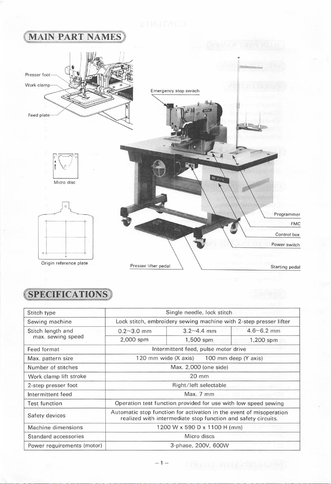
( MAIN PART NAMES)
Presser foot
Work
cia
Feed pia
Micro disc
Emergency stop
switch
r--
_l
[
_j_
Origin
reference plate
(SPECIFICATIONS)
Stitch
type
Sewing mac
Stitch
max. sew
format
Feed
Max.
pattern
Numb
Work
2-step presser
ntermittent
I
Test
function
Safety
Machine dimen
Standard
Power
hin
e
length
er of
clamp
and
ing speed
size
sti
tches
lift
stroke
foot
feed
devices
sion s
accessories
requirements
Automat
(motor)
sti
Lock
0.2-3.0
Operation
tch,
2,000
120
ic stop
realized
embroidery
mm
spm
Int
mm
test
function
with
Sing le
sew
ermittent
wide
(X
Max. 2,000
Right /
function
intermediate
1200
prov
for activation
W x
3-
phase
need
le, lock
ing
machine with 2-s
3.2-
4.4
mm
1,
500
spm
feed,
pulse
axis)
Max
590
Micro
100
(one side)
20
mm
left
selectable
. 7
mm
ided for
stop
function
D x 1100 H (mm)
discs
, 200V,
stitch
motor
mm
use
in
the
600W
deep
with
and
drive
low
event
safety
tep
4
.6-6.2
1,200
(Y
axis)
speed
of
misoperati
Programmer
Power
Starting
presser l
mm
spm
sewing
circuits.
FMC
Control box
switch
pedal
ifter
on
-1-
Page 5
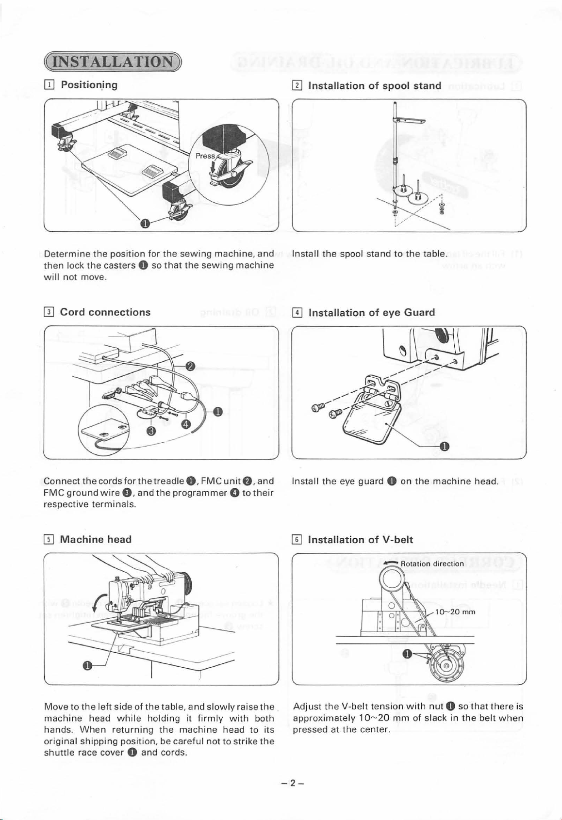
(INSTALLATION)
[I]
Position.ing
llJ
Installation
of
spool
stand
Determine
then
lock
will
not
move.
[1]
Cord
Connect
FMC
ground
respective
the
position
the
casters 0
connections
the
cords
for
wire
8,
terminals
the
and
.
for
the
sewing
so
that
the
treadle
the
0,
programmer 0 to
machine, and
sewing
FMC
machine
unit
f),
and
their
Install
[I]
Install
the
Installation
the
spool
stand
eye
guard 0 on
of
to
eye
the
table.
Guard
the
machine
head
.
IT]
Machine
Move
to
machine
hands. When
original
shuttle
race cover 0
head
the
left
head
shipping
side
of
the
while
returning
position,
and
tab
holding
the
be
careful
cords.
le,
and slowly
it
firm
machine
not
ly
head
to
raise
with
strike
both
to
the
its
the
[I]
Installation
Adjust
.
approximately 1
pressed
the
V-belt
at
the
-2-
of
V-belt
tension with
0"-'20
mm
cente
r.
of
1D--20
nut
slack
mm
0 so
in
the belt
that
there
whe
is
n
Page 6
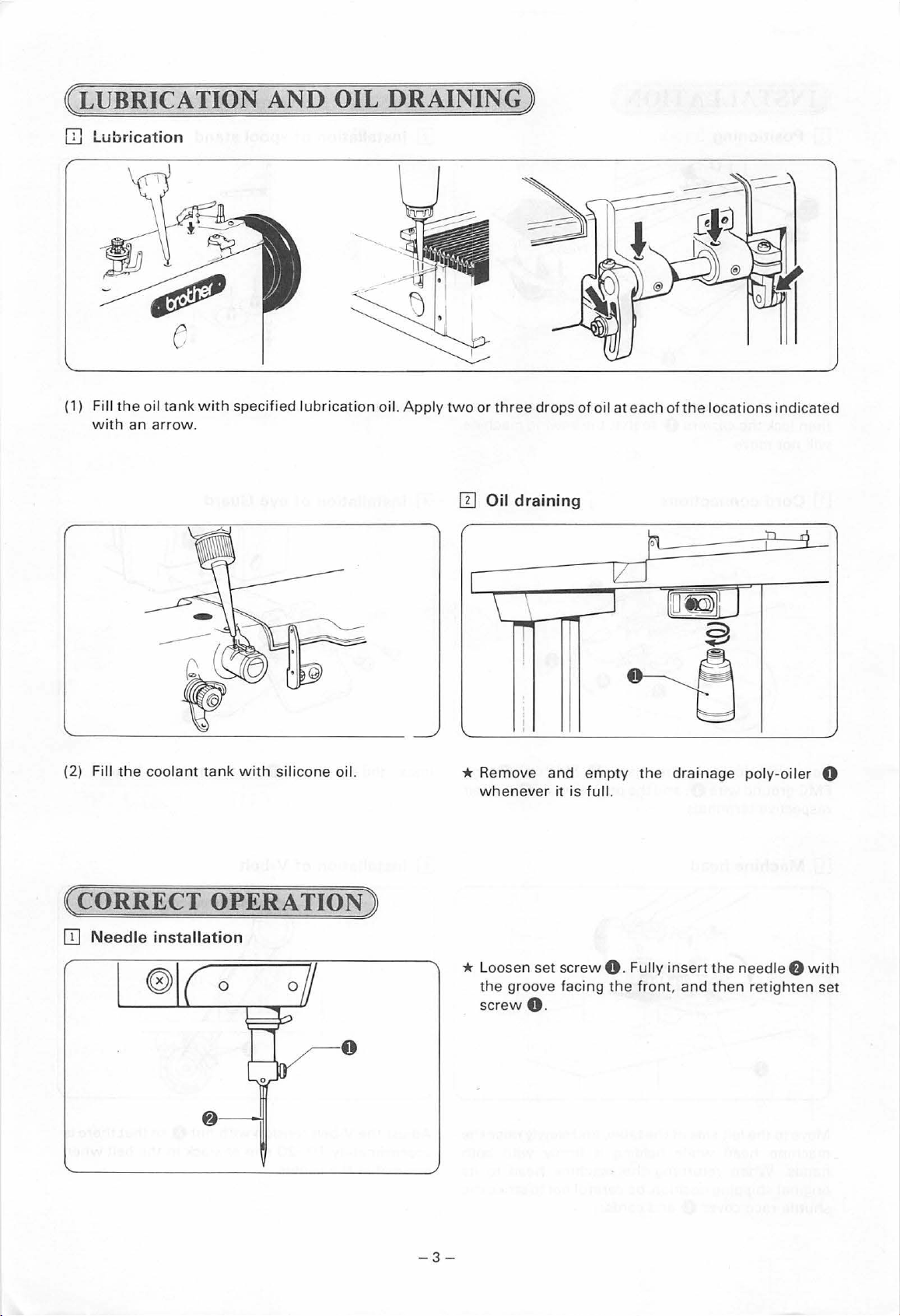
( LUBRICATION
IIl Lubrication
AND
OIL
DRAINING)
(1) Fill
with
Fi
(2)
ll
the
an
the
oil
tank
arrow
coolant
with
specified
.
tank
with silicone oil.
lubrication
oil.
Apply
two or
three
[I]
Oil draining
r
\ \
*
Remov
whenever
drops
rr
I
I
I
e and
it
of
empty
is
full.
oil
_j
at
each o
fthe
~
lL_j
l[L@J
0
~
the
drainage poly-oile
locations
t J
~
indicated
'rl
M
r 0
( CORRECT OPERATION)
OJ
Needle
installation
* Loo
sen
set sc
the
groov
e facing the
s
cr
ew O.
-
3-
rew
0 . Fully i
front
ns
ert the need
, and then retighten set
le
f)
wit
h
Page 7
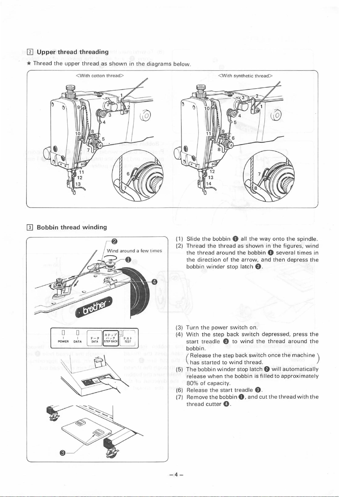
ITl
*
Thread
Upper
thread threading
the
upper
thread
<
With
cotton
as
thread>
shown
in
the
diagrams
below
.
<With
syn th
etic
thread
>
[}]
Bobbin thread
0
I
POWER
winding
(1)
Sl
ide
the
(2)
Thread
the
thread
the
direction
bobbin winder
(3)
Turn the
(4)
With
the
s
tart
tr
bobbin.
Release
(
has
started
(5)
The
bobbin
release
80%
of
(6) Release
(7)
Remove
thread
bobbin
the
thread
around
of
pow
er swit
step
ea dle e
the
step
to
winder
when
the
capacity.
the
start
the
bobbin
cutte
r 0 .
0 all
the
as
shown
the
bobbin
the
arrow
stop l
atch
f).
ch
on.
back switch
to
wind
back
switch
wind
thread.
stop l
atch
bobbin
treadle
0 .
is filled
8.
and
way
onto
the
in
the
figure
0 several
, and
then
depress
depressed, press
the
f)
cut
thread
once
the
around
the
machine
will
automatica
to
approximately
thread
spindle.
s,
wind
times
in
the
the
the
lly
with
the
)
-4
-
Page 8

(8) To
wind
screw
winder
<
Bobbin
Press
the bobbin
position,
towa
rd
more
0.
stop latch
winder
and
the
mach
thr
ead
and
adjust
mounting
winder
press the
ine pulley.
onto
the
f)
.
stop
thread
the
position
>
latch
winder
bobbin
f)
to
0-ring
0,
of
the
loosen
the
bobbin
winding
G 1
set
mm
[I]
Bobbin
(1) Pull
forward and
cover.
(2)
Lift
the
remove
case
installation
the shuttle
bobbin case latch
the
race cover 0
then
bobbin
open
case.
and
the
and
threading
In
sert
(3)
bobbin
through
pull
hol
e 0 .
turns in
arrow
pulled
the
case, pass
the
it
out
through
Make sure
the
when the
.
bobbin
cut line
direct
into the
the
thr
f)
,
the
thread
the
bobbin
ion
of
thread
ead
and
the
is
(4) Pass
through the
the
tely
the
horn,
30
mm
end
thread
and
of
of the
pull
approxima-
thr
ead
thread
hole 0 in
out.
- 5 -
Page 9

IT]
Thread
1.
Bobbin
tension
thread
tension
* The bobbin thread
that
the
bobbin
when
the
adjustment
will
suspended by
screw
tension
not descend
should be adjusted so
the
bobbin thread. Turn
0 to adjust.
of
its
own
weight
2.
Upper
Turn
upper
Adjust
th~ead
thread
the
thread
thread
thread tension control
remainder is between
tension
tension
tension to
control
the
nut
f)
to
material being sewn.
nut
0 so
30
to
40
mm.
adjust
that
the
the
3. Thread
To
adjust
loosen set
unit.
Also, slide
stitch.
5.
Upper
take-up
the
height
screw
the
thread
spring
of
the
8 and
adjustment
tension
turn
release
height
thread take-up spring,
the
entire
adjustment
unit
in
or
out
so
that
timing
4.
Thread
Adjust
the
the
tension disc opens approximately
Loosen set
upper thread
tension on the upper thread is released
thread take-up lever 0 is completely
end
take-up
the
thread take-up spring tension by
tension stud 0
screw
tension
of
a stitch.
spring
with
0 and adjust the position
tension
a screwdriver.
1.5
mm
after
release lever 8 so
lowered
turning
the
ot'the
that
when
at
final
the
the
the
-6-
Page 10

DATA LAMP
Press the data switch and
the data lamp
nate, and data
in. When the operation is
completed, the lamp
go out.
The lamp
twice
when
on to the micro disc.
POWER
Illuminates
wer
switch is turned on.
DATA
SWITCH
Initiates storage
a micro disc or reading out
of data from a micro disc.
will
will
will
illuminate
data is stored
LAMP
when
of
illumi-
be
read
will
the po-
data on
EJECT
LEVER
Press
this
lever
to
micro disc in or
TEST
LAMP
Illuminates when the test switch is turned
on.
TEST
SWITCH
Press this switch to confirm program
contents. The machine
stitch increments when the treadle is
depressed after this switch is turned on.
• Speed
STEP
The machine
is depressed when the step back switch is
pressed.
(This function is used to confirm the direction
of machine pulley rotation,
bobbin, or
position.)
foot
will
lifter
BACK
to
open the lid. Slide the
out
gently. ·
will
increase when
pedal' is pressed.
SWITCH
will
run
while
return
to
the machine stop
move in single
the
presser
the start treadle
to
wind
the
*A
previously programmed pattern can be moved vertically
r-----------,
I I
CD
I : ®
+-nl
I I
I I
._
___________
I I
ln....:
""'"?""'
J
Note:
Be
sure to stop the machine quickly
checking the direction of pulley
switch
depressed, and
Make
sure
illuminated,
(1) Hold
the
lamps have
when
rotation.
or
horizontally.
the
test
data
switch.
switches.
CD
Press.the data
one pulse (0.2
@ Press
one
pulse (0.2
® Press
the
data
(0.2 mm)
@)
Press
step back
(0.2 mm)
Press
the
mode once
the
the
the
test
the
switch
mm)
step
switch
mm)
step back
switch
to
the
data
switch
switch
to
the
switch
twice
to
twice
to
switch
to
move
back.
to
move
forward.
to
cancel
pattern has been moved to
location as described above.
both
and
then
to
move
the
left.
to
move
the
right.
once, and
the
pattern
once, and
the
pattern one pulse
the
then
the
test
release
the
the
then
then
pattern
the
press
and
pattern
pattern
press
one
pulse
press
transfer
desired
data
the
the
Page 11

OJ
[I]
Data
Step
switch
0
I
POWER
back
use
Data lamp
svVitch use
*This
(1)
(2) Press
switch
on a micro disc
programmed pattern data
Insert a micro disc on
been recorded
illuminate
being read out. The data
when
is being stored onto a disc. The emergency stop
lamp
will
data cannot be read
is used
the
data switch. The data lamp
to
data is being read out, and
illuminate
to
into
into
the FMC.
indicate
if
read pattern data recorded
the
machine, or
onto a micro
which
stitch pattern data has
that
stitch pattern data is
lamp
will
the
disc has bad sectors and
or
stored.
disc.
illuminate
twice
when
to
store
will
once
data
0 0
I I
POWER
DATA
* This switch is used
at a time
resewing in
bobbin thread runs
switch
broke
large patterns.
(1) Press
machine is running.
the emergency
(2) Press
The emergency stop
(3) Press
reverse one stitch at a
switch
(4)
When
position,
presser foot is stopped too soon, simply press
step back
foot movement.
(5) The machine
treadle 0 is pressed.
* Turn
0
forward. The presser foot
stitch
time.
in
to
or
ran out. This is especially useful
the
the
the
is depressed.
the
release the step back switch. If
switch
the
test
to
move
units
the
return
emergency stop
emergency stop
step back switch. The presser foot
presser foot has returned
the
ifthe
to
move
reverse
the
stop·lamp
will
switch
presser foot one
sewing
event
the
out
to
the point
All
lamp
time
again
to
start
on and press
step back
in
operations
sewing
the
machine one stitch
direction
thread breaks or
mid-pattern. Use
where
switch 0 while
will
will
illuminate.
switch
will
as long as
resume reverse presser
switch
0 once again.
go out.
when
the
stitch
will
advance in
is pressed at
the
to
to
enable
the
this
the
thread
with
the
stop and
will
step back
the
desired
the
the
the
start
start treadle
at a
time
·1
00
this
-8-
Page 12

[I]
Test
switch
use
D D
I I
POWDI
DATA
*This
(1)
(2) Press
(3) Press
(4) Press the test switch. The test lamp
(5) Press
(6)
(7) Press
* The presser foot
switch is used to recommence sewing from
the
any position in
breaks or
pattern.
Press
machine is running. All operations
the
emergency stop lamp
The emergency stop lamp
automatically
move
stitch at a
lifter
When
position, press
foot
will
presser foot was stopped too soon, simply press
the
test
advancing again.
the step back
switch
the
test
will
foot
step back
increas
the
the
emergency stop switch 0
the
emergency stop switch 0 once again.
the
start treadle
the
start treadle
but
the presser foot
time
pedal 8
the
presser foot has reached
stop, and
switch
the
start treadle 8
is on. If
switch
reverse one stitch at a
switch
if
the presser foot
pattern in
bobbin thread runs
return
to
f).
at
low
speed. Press
to
increase
the
test
the
test lamp
again;
switch
the
the
will
advance in
step back switch is pressed after
has been
is depressed. The speed
the
event
out
will
will
illuminate.
will
go out.
f).
The presser foot
the
sewing start position.
will
illuminate.
The
work
clamp
will
begin advancing one
the
presser foot
the
speed.
the
switch
is pressed
again. The presser
will
go out. If
presseer foot
to
begin sewing again.
100
stitch
while
turned
lifter
off,
time
as long
pedal8
the
is pressed.
th·e
while
thread
in
mid-
the
stop and
will
will
not
desired
the
will
start
units
the
test
presser
as
the
will
if
[I)
Emergency
(Also serves
(2)
If
the
emergency stop
All machine functions
again
to
(3) Abnormal machine operation
The emergency stop
emergency lamp
oper~tion.
stop
switch
__
____,
as
lamp)
cancel
the
emergency stop mode.
will
The emergency stop mode
use
switch
will
stop and
function
illuminate
* The machine
pressed
(1
) If
the
during
All machine functions
gency stop
problem has been solved, press
switch
stop
operate,
cancelled, and
* Neither treadle
stop lamp is on.
0 is turned
will
if
an abnormal load is applied or a malfucntion is detected during machine
ON
during test switct) operation
the
emergency lamp
automatically engage, all machine operations
will
be cancelled
will
go on. Press
when
the emergency stop
will
stop immediately
while
sewing or test
emergency stop
sewing.
switch
lamp
0 again;
the
emergency stop
the
lamp
will
work
the
if
this
switch
switch
will
stop, and
will
the
thread cutter
will
go out.
while
emergency stop
will
switch
operation.
0 is
go on. Once
the
function
the
stop, and
is pressed.
turned
the
emergency
emergency
switch
switch
emer-
will
will
the
is
ON
the
be
0
-9-
Page 13

( SEWING)
ITl
Micro
disc
insertion
Press the lever
¢
Turn
the p
ower on
(1) Two patterns. one per side, can be recorded
Ea
Note: Micr
IT]
Sewing
ch patte
rn
can
o discs
producing
Also
be
speed
(
t
;J~
POWER
be
up
shou
a magne
carefu
l of
adjustment
~~
SPEED
<®
to
a max
imum
ld be stored
tic
field. Magnetic
dust
, oil,
4 I 6
' .
,.
2 0 8
,.
....
0
10
L...--
2000
away
from
and
other foreign
0
Slide the micro disc in ge
w ith t
he
on
each
mic
stitches
fields may
.
magnets,
radios, televis
erase or
matter
(1)
Turn
se
(2)
Sewing
for
Stitch length
(mm)
Sewi
(spm)
indents facing f
ro
disc
.
damage di
.
the
stepless speed
wing
speed .
speeds
different stit
ng speed
ntl
y
orwa
rd
ion
s, and
sc conte
vary
as
show
ch len
gths
0.2- 3.0 3.
850- 2,000
Close
the
other
electronic products
nts
.
cont
rol 0
to
n in the
.
2-4.4
550-
1,500 400- 1,200
lid.
any
des
below
4.6- 6.2
ired
table
*
Before
Sewing
0 0
I I
POWER DATA
(1)
(2)
With
the
step back
f)
a
nd start
Th
e mac
released,
desc
end
presser
swi
bar
lifter
tch depressed, press
sewing.
hine wi
and
ll s
the
top
when
presser
.
plate
the
foot
0 raised,
the
start trea
start
treadle
lift
er plate 0
hold
f)
the
dle
is
will
- 10 -
Page 14

[}]
Sewing
Data lamp
(1) Turn
(2)
(3) Press the data switch. The data
(4) Press
(5) Press
(6) Press
the
power on.
Insert a micro disc.
illuminate, data
will
go
out
the
work
clamp, insert material under
and
then
press
lower
the
the
will
return
start position.
the
machine
will
will
be read in, and
when
completed.
presser foot
the
presser foot
work
clamp.
start treadle
to
the
origin, and move
start treadle 0 once again, and
begin sewing.
the
lifter
treadle 8
the
lifter
0.
The feed mechanism
to
lamp
data lamp
to
raise
work
clamp,
treadle 8
the
sewing
will
the
to
the
[I]
Rotary
Open
remove
the
the
shuttle
hook
cleaning
race cover, and
bobbin case.
Slide
the
shuttle
0
in
the
direction
to
open the
and then remove the
race body 8 and
race body latch
of
shuttle
race body,
shuttle
••
the
shuttle
arrow
body
Use a screwdriver 8
ly pointed object
thread or other foreign matter
from
the
rotary hook thread
guide and
drop
cleaning is completed.
of
shuttle
oil
to
or
to
remove any
race.
the
race
similar-
Apply
when
a
-11-
Page 15

(
STANDARD
*
Turn
the
machine
[I]
Needle
Turn
the
needle bar so
needle
*
Align
II]
Needle
bar
height
pulley
to
that
bar
bushing
the
second reference
bar
lift
ADJUSTMENTS)
pulley
comp
reference line@.
0.
stroke
by
hand when
adjustment
lete
ly lower
line,@,
adjustment
the
needle
the top
with
making
reference line
the
any
bar. Remove cap
bottom
adjustments
f),
loose n
on
the
needle bar, is a
of
the
needle
bar
set
busing
screwO. and
lign
ed
with
when
using
vertically adju
the
bottom
needle
DP x 17
st
of
the
the
.
Turn
top,
the
* A
(I]
the
pulley
with
the
shuttle
lign
the
Needle
to
bottom
hook
bottom
to
shuttle
raise
of
point
reference
----;t---0
the
need le bar
the
needle
is ali
hook
-----
bar
gned
with the needle
line,@, with
point
.01-0.08
from
the
bushing
the
gap
adjustment
mm
'0
0.
needle
Now
center
bottom
lowest
, loosen A llen sc
of
.
the
position
need le bar
and
rew
bushing
align
reference line®.
f)
and
turn
when
the
using
shuttle
needle
second fr
driver
so
DP x 17
om
that
.
Turn
the pulley
connecting
link
and
stud
align
f)
the
to
shuttle
adjust
the
hook
needle
point
to
with
needle
shuttle
-12
hook ·
-
center
point
. Loosen set
gap
screw
to
0.01-D.OB
0 and
mm
.
turn
the
ecce
ntric
Page 16

0
Shuttle
Turn
the
pulley
connecting
will
result
point
will
II]
Shuttle
driver needle
and
align
link
stud
f)
in
skipped
interrupt
hook
stitches.
the
thread
contact
the
rotary
so
that
needle,
guide
hook
the
needle
Also,
if
resulting
adjustment
adjustment
point
with
meets
the
needle
in
abnormal abrasion
the
needle center. Loosen set
the
shuttle
does
not
driver.
sufficient
.
Note
ly
that
contact
screw 0 and
excessive
the
shuttle
needle
driver,
turn
the
to
driver cont
the
eccen
rotary
tric
act
hook
[I]
Presser plate
lift
stroke
adjustment
Adjust
thread guide
width, slide
retighten
so
that
the
the needle
0 is
at
the
thread
screws.
groove
the
middle of
guide light
of
the shutt
the
nee dle zigzag
ly
in, and
le
hook
then
The
presser
machine
presser
presser
plate l
ift
stroke
is stopped. To adjsut, l
arm
stoppe
plate lift
r
f)
stroke,
so
increase
is a
maximum
ower the
that the
presser
the
presser
20
work
plate 0 to
mm
from the needle plate
cia mp,
loosen
pre
plate 0 to
set
sser arm
presser
screw
arm
8,
stoppe
stopper
-13-
top
and
to
presser plate
vert
ically
r
f)
gap is 1
f)
gap.
bottom
adjust the
mm.
To decrea se
when
position
of
the
the
the
Page 17

[I]
Movable
0
knife
adjustment
Loosen set
groove
<Movable
(1) Open the
(2) Remove
(3) Remove set screws 8 and
remove the needle plate.
of
screw
the
shuttle
and
shuttle
the
8 and adjust
hook thread guide 8
fixed
knife
replacement>
race cover.
thread
cutter
the
thread cutter lever 0 so
when
connecting
flat
rod.O.
screws
8.
and
that
the
movable knife 8
the
machine is stopped.
(4) Remove the movable knife
new
movable knife.
tip
aligns
with
0 and replace
the
needle
with
a
Set
the
(5) Remove the fixed knife
new
fixed knife.
fixed knife 8 gap is
of
the
fixed knife 8 does not extend beyond
left
side
of
Adjust
the
needle plate.
0.5
8,
and replace
so
the
mm.
Be
with
needle plate 8
sure
the
left
a
to
side
the
(6)
the
connecting rod O.
* Make sure
after
-14-
thread
movable
installing
cutter
knife
the
connecting rod 8 pin
link
8 and thread
movable knife is properly aligned
the
needle plate.
into
cutter
Page 18

[!]
Presser
foot
adjustment
~
3.5
mm---r----
1
*Turn
(1) Loosen set screw
(2)
(3) Standard vertical presser foot stroke is 3.5 mm. If
(4)
the
pulley and
down
position before making
ment.
the
presser foot
material.
* The material
foot is too low, and stitches may skip
presser foot is too high.
Turn
the pulley by hand and make sure
the
screw
link
center
8.
Lower the feed
screw
feed shaft
enters
If it does not come
loosen
adjust.
the
stroke is excessive, loosen
feed
stroke.
If vertical presser foot movement is not necessary,
loosen step
intermittent
lower
0,
and
f)
bottom lightly touches
will
be improperly fed
of
the
hole
to
the center, remove cap
e.
and move
8,
and secure
8.
the
presser
the
then
retighten it so
in
the
the
nut
link
foot
to
below
presser foot
presser foot
if
the
the
adjsut-
presser
if
needle
0 and raise
to
decrease
link
L 0 to
the
that
the
the
8.
0.
to
the
the
the
·
[!]
(1)
(2)
Thread
Adjust
Work
that
footO.
wiper
the solenoid lever 8 so
the
the
wiper 0 to
thread
adjustment
wiper
0 so
needle
that
point
that
the
thread
it is aligned
gap is
approximately2
with
-15-
wiper
the
0 is level
center
mm.
oft
Be
when
he needle bar. Slide
sure
the
the
machine is stopped.
the
wiper
0 does
not
wiper
strike
0 in
the
or
out so
presser
Page 19

liQ]
Needle
Need le
(1)
Adjust element
pos
ition
(2)
Adjust
needle
the
mater
* The feed
movement
[ill Origin
and feed
up
position
0 so
.
the
needle and feed
has
been
removed
ial.
timing
and
adjustment
timing
o~"'"
The
should be ali
the
the
that
from
shou
ld be increased
improve
adjustment
element
needle
up
the
timing
sewing
and
gned
crank
position.
needle
with
the
mater
effic
magnet
when
is
in
tip
is
19
element
ial,
and
when
iency.
mm
f)
so
sewin
Rotation
k -
above
so
that the
that
the
g heavy
direction
the
needle
feed
feed
materials. This
plate
mechanism
mec
hanism
when
stops
will
23
The
should
the needle
above
position.
the
begins
before
decr
ease need le
,~~V";'"
-
t~
element
and
aligned
tip
is
needle
needle
magnet
2 mm
down
after
sidewise
be
the
needle is in
to
operate
the
when
the
enters
up
the
*The
Pl
~
/
X
'"\_
Y
""-
orig
in (X-
0,
Y-0)
< X
(1) Remove
(2) Loosen set
origin
plate w
the origin
axis
f)
0
ith
>
.
latera
is
at
the
the
orig
.
swatooth
screw
lly
to
adjust.
middle
in
reference
presser
0 .
and
fro
nt. Replace
plate 0
fo
ot L 0
move
X-axis
and
the
feed
to
adjust
sawtooth
origin
dog
L
-1
6-
Page 20

1m
2-Step
presser
foot
operation
adjustment
<Y
axis>
( 1 ) Remove
(2) Loosen Allen bolt
8 forward or back
Turn
the
(1) Presser foot motion can
the
bottom left
the
power
settings
rear cover
f),
and
to
adjust.
off
and then open
of
dip switches 1, 2, and 3 0 on
of
the
control circuit board.
0.
.move
Y-axis origin dog
the
control box.
be
adjusted by adjusting
the
•
OFF
1~:
2
3
OFF
,..-·-
'
~
__
-c,.""
ON
ON
:Ill
The presser foot
The presser foot
sewing is completed.
First
switch
Second
switch
will
will
ON: Presser left 8 descends.
ON:---Presser
rise automatically
rise
when
the
presser bar
When the presser foot lifter treadle 8 is pressed, presser
right
8.
simultaneously. The work clamp (pressers right and left)
and the presser foot
descend. (The presser foot
switch.)
presser left
right
when
sewing is completed.
lifter
treadle is pressed
8.
and the presser foot 8
will
appear
lifter treadle is a
as
below
will
when
two
all rise
position
8 and presser foot 8 descend.
when
they
First
switch
Second
switch
First
Second
ON:----Presser
switch
switch
ON: Presser
ON: Presser right 8 and presser
ON:---Presser
right 8 descends.
left
8 and presser foot 8 descend.
foot 8 descends.
-17-
left
8 descend.
Page 21

liT!
Timing
belt tension
adjustment
(1)
(2) L
Remove
presser
oosen
adj
ustment
The
timing
no
give
sawtooth
L
f).
nut
8
screw 9 to
belt 0 shoul
when
pressed
presser
and scr
d be
firm
R 0
ew
adjust.
adjusted
ly by
0.
hand.
and
sawtooth
and
turn
so
that there is
the
- 18 -
Page 22

(()lfERATION
;FLOW
CHART)
Power
switch
Data switch on - - Micro disc reading
Depress presser foot
treadle
Depress presser foot
treadle
Test
switch
Depress start treadle -
on -
lifter-
lifter-
on -
START
-Work
-Work
-Test
-Presser
clamp rises; set
material.
clamp descends.
lamp illuminates.
foot stops at sewing
start position.
Power switch on -
Data switch on - - Micro disc reading
Depress presser foot
threadle.
Depress presser foot
treadle.
To
change pattern
lifter-
lifter-
- Work clamp rises.
*
Replace presser foot, feed
plate; confirm needle
descent.
*Set
material
in
place.
Depress start
Test
switch
Depress start
treadle-
off-
treadle-
-Feed
-Feed
- Test lamp goes out.
- Machine, feed operate.
-Stop--thread
drive (pulse motor)
(confirm
presser foot and work
operation.)
} Max. 2,000
needle descent,
stop
spm.
cutting
I
Work clamp rises
clamp
When thread breaks
bobbin
Press emergency stop swtich.
Press emergency stop switch.
Press step back switch. -
thread
-Lamp
-IE
-Lamp
- Presser foot moves one
or
runs
out
illuminates.
Remove problem
goes out.
at
stitch
direction.
a time in reverse
Press step back switch. -
One machine cycle
pleted
com-
I
-19-
-Presser
foot stops.
 Loading...