

Page 1
SERVICE MANUAL
BAS-311H
Please read this manual before making any adjustments.
DIRECT DRIVE
PROGRAMMABLE ELECTRONIC PATTERN SEWER
Page 2

This service manual is intended for BAS-311H; be sure to read the BAS-311H instruction manual
before this manual.
Carefully read the “SAFETY INSTRUCTIONS” below and the whole of this manual to understand this
product before you start maintenance.
As a result of research and improvements regarding this product, some details of this manual may not
be the same as those for the product you purchased.
If you have any questions regarding this product, please contact a Brother dealer.
BAS-311H
Page 3
SAFETY INSTRUCTIONS
[1] Safety indications and their meanings
This service manual and the indications and symbols that are used on the machine itself are provided in order to ensure safe
operation of this machine and to prevent accidents and injury to yourself or other people.
The meanings of these indications and symbols are given below.
Indications
DANGER
The instructions which follow this term indicate situations where failure to follow the
instructions will result in death or serious injury.
WARNING
CAUTION
Symbols
…………………
…………………
…………………
The instructions which follow this term indicate situations where failure to follow the
instructions could result in death or serious injury.
This instructions which follow this term indicate situations where failure to follow the
instructions may result in minor or moderate injury.
This symbol (△) indicates something that you should be careful of. The picture inside the
triangle indicates the nature of the caution that must be taken.
The symbol ( ) indicates something that you must not do.
The symbol (●) indicates something that you must do. The picture inside the circle indicates
the nature of the thing that must be done.
(For example, the symbol at left means “you must make the ground connection”.)
BAS-311H
i
Page 4
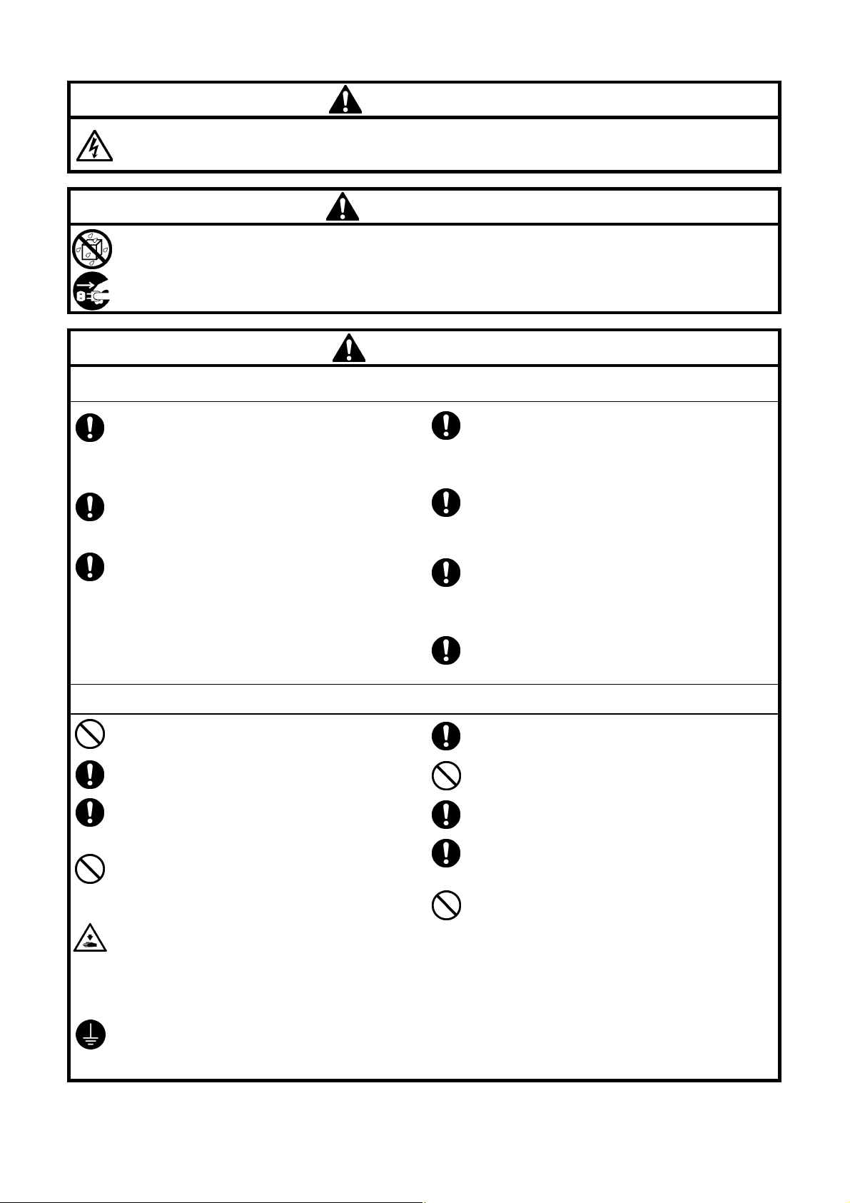
[2] Notes on safety
Wait least 5 minutes after turning off the power switch and disconnecting the power cord from the wall outlet
before opening the control box cover. Touching areas where high voltages are present can result in severe injury.
Do not allow any liquids to get onto this sewing machine, otherwise fire, electric shocks or operating problems
may occur.
If any liquid gets inside the sewing machine (machine head or control box), immediately turn off the power and
disconnect the power plug from the electrical outlet, and then contact the place of purchase or a qualified
technician.
DANGER
WARNING
CAUTION
Environmental requirements
Use the sewing machine in an area which is free from
sources of strong electrical noise such as electrical
line noise or static electric noise.
Sources of strong electrical noise may cause
problems with correct operation.
Any fluctuations in the power supply voltage should
be within ±10% of the rated voltage for the machine.
Voltage fluctuations which are greater than this may
cause problems with correct operation.
The power supply capacity should be greater than the
requirements for the sewing machine’s power
consumption.
Insufficient power supply capacity may cause
problems with correct operation.
Installation
Machine installation should only be carried out by a
qualified technician.
Contact your Brother dealer or a qualified electrician
for any electrical work that may need to be done.
The sewing machine weights approximately 88 kg.
The installation should be carried out by two or more
people.
Do not connect the power cord until installation is
complete. If the foot switch is depressed by mistake,
the sewing machine might start operating and injury
could result.
Hold the machine head with both hands when tilting it
back or returning it to its original position.
Furthermore, do not apply excessive force when
tilting back the machine head. The sewing machine
may become unbalanced and fall down, and serious
injury or damage to the sewing machine may result.
Be sure to connect the ground. If the ground
connection is not secure, you run a high risk of
receiving a serious electric shock, and problems with
correct operation may also occur.
The pneumatic delivery capability should be greater
than the requirements for the sewing machine’s total
air consumption.
Insufficient pneumatic delivery capability may cause
problems with correct operation.
The ambient temperature should be within the range
of 5℃ to 35℃ during use.
Temperatures which are lower or higher than this
may cause problems with correct operation.
The relative humidity should be within the range of
45% to 85% during use, and no dew formation should
occur in any devices.
Excessively dry or humid environments and dew
formation may cause problems with correct operation.
In the event of an electrical storm, turn off the power
and disconnect the power cord from the wall outlet.
Lightning may cause problems with correct operation.
All cords should be secured at least 25 mm away
from any moving parts. Furthermore, do not
excessively bend the cords or secure them too firmly
with staples, otherwise there is the danger that fire or
electric shocks could occur.
Install the safety covers to the machine head and
motor.
If using a work table which has casters, the casters
should be secured in such a way so that they cannot
move.
Be sure to wear protective goggles and gloves when
handling the lubricating oil and grease, so that they
do not get into your eyes or onto your skin. If the oil
and grease get into your eyes or onto your skin,
inflammation can result.
Furthermore, do not drink or eat the lubricating oil or
grease. They may cause diarrhea or vomiting.
Keep the oil out of the reach of children.
ii
BAS-311H
Page 5
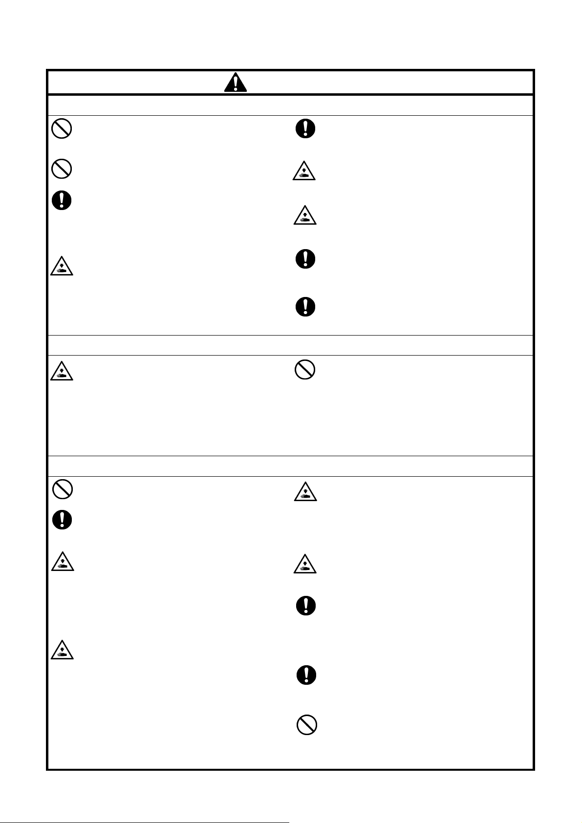
This sewing machine should only be used by
operators who have received the necessary training
in safe use beforehand.
CAUTION
Sewing
If using a work table which has casters, the casters
should be secured in such a way so that they cannot
move.
The sewing machine should not be used for any
applications other than sewing.
Be sure to wear protective goggles when using the
machine.
If goggles are not worn, there is the danger that if a
needle breaks, parts of the broken needle may enter
your eyes and injury may result.
Turn off the power switch at the following times. If the
foot switch is depressed by mistake, the sewing
machine might start operating and injury could result.
・ When threading the needle
・
When replacing the bobbin and needle
・
When not using the machine and when leaving
the machine unattended
Cleaning
Turn off the power switch before carrying out
cleaning. If the foot switch is depressed by mistake,
the sewing machine might start operating and injury
could result.
Attach all safety devices before using the sewing
machine. If the machine is used without these
devices attached, injury may result.
Do not touch any of the moving parts or press any
objects against the machine while sewing, as this
may result in personal injury or damage to the
machine.
If an error occurs in machine operation, or if abnormal
noises or smells are noticed, immediately turn off the
power switch. Then contact your nearest Brother
dealer or a qualified technician.
If the machine develops a problem, contact your
nearest Brother dealer or a qualified technician.
Be sure to wear protective goggles and gloves when
handling the lubricating oil and grease, so that they
do not get into your eyes or onto your skin. If the oil
and grease get into your eyes or onto your skin,
inflammation can result.
Furthermore, do not drink or eat the lubricating oil or
grease. They may cause diarrhea or vomiting.
Keep the oil out of the reach of children.
Maintenance and inspection
Maintenance and inspection of the sewing machine
should only be carried out by a qualified technician.
Ask your Brother dealer or a qualified electrician to
carry out any maintenance and inspection of the
electrical system.
Turn off the power switch and disconnect the power
cord before carrying out the following operations. If
the foot switch is depressed by mistake, the sewing
machine might start operating and injury could result.
・ Inspection, adjustment and maintenance
・
Replacing consumable parts such as the rotary
hook
Disconnect the air hoses from the air supply and wait
for the needle on the pressure gauge to drop to “0”
before carrying out inspection, adjustment and repair
of any parts which use the pneumatic equipment.
Hold the machine head with both hands when tilting it
back or returning it to its original position.
Furthermore, do not apply excessive force when
tilting back the machine head. The sewing machine
may become unbalanced and fall down, and serious
injury or damage to the sewing machine may result.
If the power switch needs to be left on when carrying
out some adjustment, be extremely careful to observe
all safety precautions.
When replacing parts and installing optional
accessories, be sure to use only genuine Brother
parts.
Brother will not be held responsible for any accidents
or problems resulting from the use of non-genuine
parts.
If any safety devices have been removed, be
absolutely sure to re-install them to their original
positions and check that they operate correctly before
using the machine.
To prevent accidents and problems, do not modify
the machine yourself.
Brother will not be held responsible for any accidents
or problems resulting from modifications made to the
machine.
BAS-311H
iii
Page 6
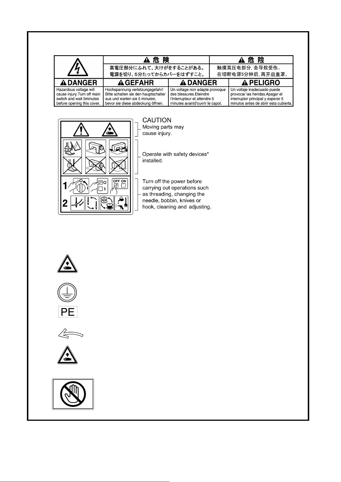
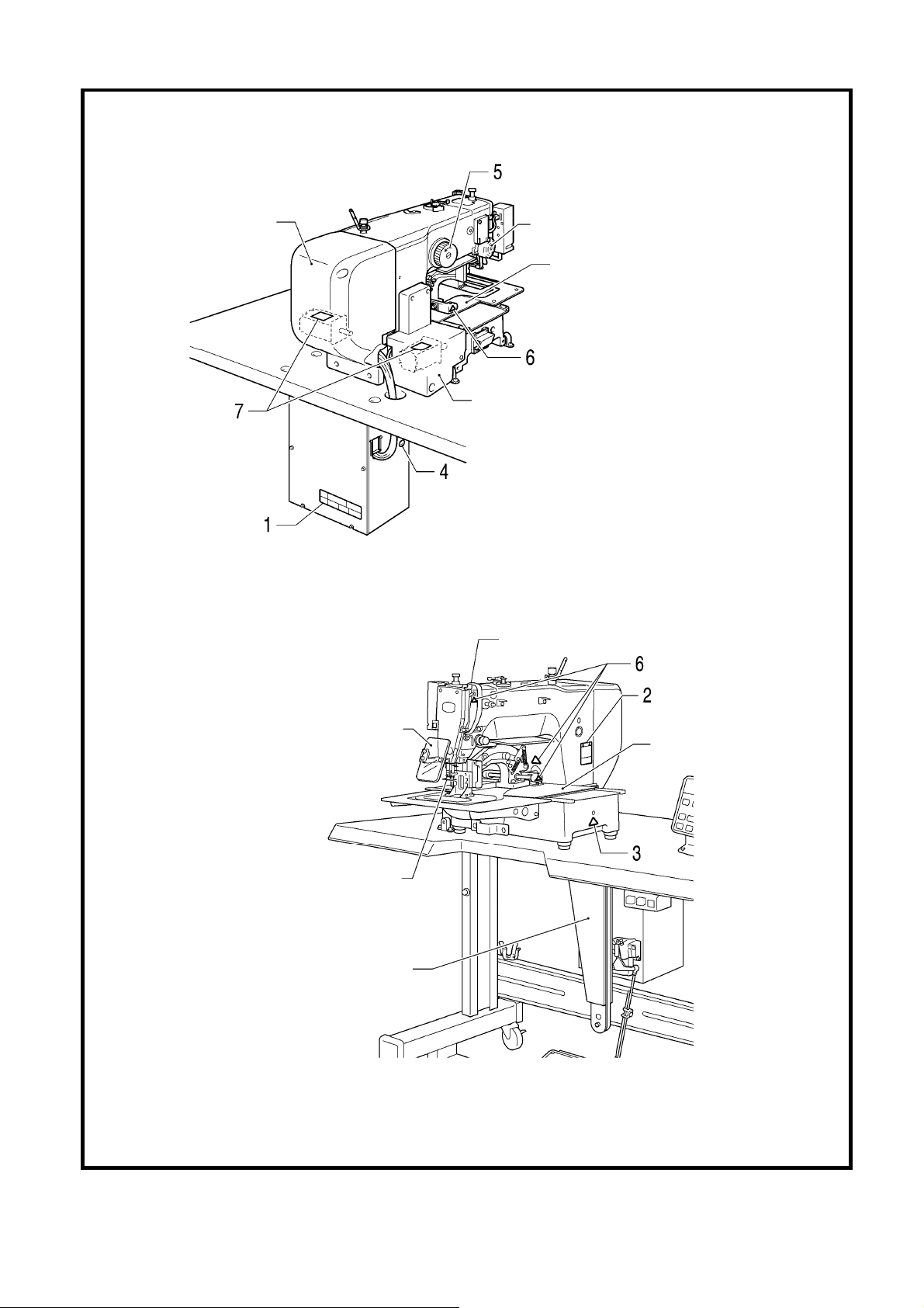
[3] Warning labels
r
The following warning labels appear on the sewing machine.
Please follow the instructions on the labels at all times when using the machine. If the labels have been removed or are
difficult to read, please contact your nearest Brother dealer.
1
2
3
4
5
6
7
*安全保護装置:
*Safety devices
Devices such as eye guard, finger guard, thread take-up cover,
side cover, rear cover, tension release solenoid cover, inne
cover, outer cover, fixed cover and gas spring support cover
Be careful not to get your hand caught when tilting back the machine head and
returning it to its original position.
Be sure to connect the ground. If the ground connection is not secure, you run a high
risk of receiving a serious electric shock, and problems with correct operation may also
occur.
Direction of operation
Be careful to avoid injury from moving parts.
Do not hold, otherwise problems with operation or injury may occur.
iv
BAS-311H
Page 7
Rear cover
Side cover
Tension release solenoid cover
Inner cover L
Outer cover
Fixed cover
Thread take-up cover
Eye guard
Finger guard
Gas spring support cover
3228B 3029B
Inner cover R
Outer cover
Fixed cover
BAS-311H
v
Page 8

CONTENTS
1. SPECIFICATIONS·································· 1
2. NOTES ON HANDLING························ 2
3. FUNCTION SETTINGS ························· 3
3-1. List of special functions when power is
turned on ····················································· 3
3-2. List of advanced functions··························· 5
3-3. Setting memory switches (Advanced)········· 6
3-4. List of memory switches ······························ 7
3-5. Setting the work clamp mode ···················· 23
3-6. Error history checking method··················· 25
3-7. Input checking method ······························ 26
3-8. Output checking method ··························· 29
3-9. Confirming software version······················ 31
3-10. Protection settings··································· 32
4. X AND Y PARALLEL MOVEMENT OF
SEWING PATTERNS ·························· 35
5. USING SD CARD································· 37
5-1. Notes on handling SD cards (commercially
available) ··················································· 37
5-2. Structure of an SD card folder··················· 37
5-3. Preparation for reading and writing data ··· 38
5-4. [ r 1] Reading additional sewing data······ 39
5-5. [ w 2] Writing additional sewing data to
an SD card················································· 40
5-6. [ r 3] Reading memory switch data ········· 41
6. MECHANICAL DESCRIPTIONS········ 49
6-1. Needle bar and thread take-up
mechanisms ·············································· 49
6-2. Lower shaft and shuttle race
mechanisms ·············································· 49
6-3. Work clamp lifter mechanism (Motor-driven
work clamp specifications) ························ 50
6-4. Work clamp lifter mechanism (Pneumatic
work clamp specifications) ························ 51
6-5. Intermittent presser foot lifter
mechanism ················································ 51
6-6. Intermittent presser foot stroke
mechanism ················································ 52
6-7. Feed mechanism······································· 53
6-8. Thread trimmer mechanism ······················ 54
6-9. Tension release mechanism······················ 55
6-10. Thread wiper mechanism························ 55
7. ASSEMBLY ··········································· 56
7-1. Upper shaft mechanism ···························· 56
7-2. Needle bar mechanism ····························· 58
7-3. Intermittent presser foot lifter
mechanism ················································ 60
7-4. Work clamp lifter mechanism (Motor-driven
work clamp specifications) ························ 62
7-5. Work clamp lifter mechanism (pneumatic
work clamp specifications) ························ 65
7-6. Feed mechanism······································· 67
5-7. [ w 4] Writing memory switch data to the
SD card······················································ 42
5-8. [ r 5] Reading program data ···················· 43
5-9. [ w 6] Writing program data to an SD
card ··························································· 44
5-10. [ r 7] Reading sewing machine data····· 45
5-11. [ w 8] Writing sewing machine data to
an SD card ·············································· 46
5-12. [ w 9] Writing error log data and memory
switch log data to an SD card ·················47
5-13. Updating the control program version····· 48
7-7. Work clamp arm mechanism····················· 72
7-8. Feed covers··············································· 73
7-9. Lower shaft mechanism ···························· 74
7-10. Shuttle hook mechanism························· 76
7-11. Thread trimmer mechanism ···················· 77
7-12. Tension release mechanism ··················· 81
7-13. Thread wiper mechanism························ 82
7-14. Auxiliary plate·········································· 83
7-15. Covers····················································· 84
BAS-311H
Page 9

8. ADJUSTMENT······································ 85
8-1. Checking the machine head switch ···········85
8-2. Standard thread tension·····························86
8-2-1. Upper and lower thread tension·········86
8-3. Thread take-up spring································87
8-4. Arm thread guide R····································87
8-5. Adjusting the needle bar height ·················88
8-6. Adjusting the timing and the driver needle
guard··························································88
8-7. Adjusting the needle clearance··················89
8-8. Adjusting the shuttle race thread guide ·····89
8-9. Rotary hook lubrication amount ·················89
8-10. Adjusting the thread trimmer cam
position ····················································90
8-11. Adjusting the position of the movable
knife ·························································90
8-12. Replacing the movable and fixed
knives·······················································92
8-13. Installing the feed plate····························93
8-14. Adjusting the thread wiper ·······················94
8-15. Presser foot installation position··············94
10. ELECTRIC MECHANISM ··············· 113
10-1. Precautions at the time of adjustment··· 113
10-2. Components inside and outside the
control box and in the operation
panel······················································ 114
10-3. Fuse explanation··································· 115
10-4. Description of connectors ····················· 116
10-4-1. Connector positions······················· 116
10-4-2. Symptoms when there are poor
connections···································· 118
10-5. Troubleshooting ···································· 122
10-5-1. Troubleshooting flowchart·············· 122
10-5-2. Problem solution and measures ···· 126
11. LIST OF ERROR CODES ···············141
12. TROUBLESHOOTING ····················148
13. 7-SEGMENT DISPLAY LIST ··········152
8-16. Adjusting the intermittent work clamp······95
8-17. Adjusting the work clamp lift amount·······98
8-18. Adjusting the air pressure (pneumatic
work clamp specifications)·······················98
8-19. Belt tension adjustment ···························99
8-20. Adjusting the tension release amount ···100
8-21. Adjusting the backlash of the lower
shaft gear···············································101
8-22. Adjusting the home position ··················102
8-22-1. Work clamp lift home position ········102
8-22-2. X-Y feed home position ··················105
8-23. Adjusting the motor standard position···108
8-24. Adjusting the needle up stop position····109
8-25. Setting method for standard depression
strokes (Foot switch) ·····························110
9. APPLYING GREASE
(FEED MECHANISM) ························ 111
BAS-311H
Page 10
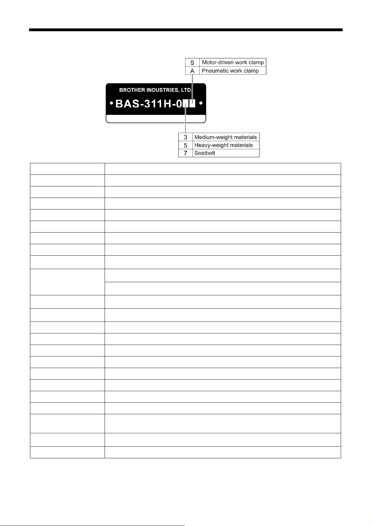
1. SPECFICATIONS
1. SPECFICATIONS
Sewing machine Lock stitch pattern tacking sewing machine (with large shuttle hook)
Stitch formation Single needle lock stitch
Max. sewing speed 2,800 sti./min
Max. sewing area (XxY) 150 x 100 mm
Feed mechanism Intermittent feed, pulse motor drive
Stitch length
No. of stitches 500,000-stitch internal memory (*1)
Maximum No. of stitches 20,000 stitches (per program)
No. of sewing data items
that can be stored
Work clamp lift method
Work clamp height
Intermittent presser foot lift
amount
Intermittent stroke
Motor-driven work clamp specifications: Pulse motor drive method
Pneumatic work clamp specifications: Pneumatic method
Motor-driven work clamp specifications: Integrated-type work clamp
Pneumatic work clamp specifications: Separate-type work clamp
Internal memory: 512 (*1), SD card: 900
Motor-driven work clamp specifications: Max. 25 mm
Pneumatic work clamp specifications: Max. 30 mm
2 − 4.5 mm, 4.5 − 10 mm or 0 (Default setting 3 mm)
0.05 − 12.7 mm
22 mm
3190B
Hook Double-capacity shuttle hook (standard shuttle hook sold separately)
Wiper device Standard equipment
Thread trimmer Standard equipment
Data storage method Internal memory (Flash memory), SD card (*2)
User programs 900
Cycle programs 30
Motor 550 W AC servo motor
Weights
Power source
Air pressure 0.5 MPa 1.8 l/min.
(*1) The number of data items and stitches that can be stored will vary depending on the number of stitches in each
program.
(*2) No guarantees of operation can be given for any media.
(For single-phase 110V and three-phase 380V / 400V, the trans box is required.)
Machine head approx. 88 kg, operation panel approx. 0.4 kg
Control box 9 kg (Differs depending on destination)
Single-phase 110V / 220V / 230V, 3-phase 220V / 380V / 400V
1
BAS-311H
Page 11
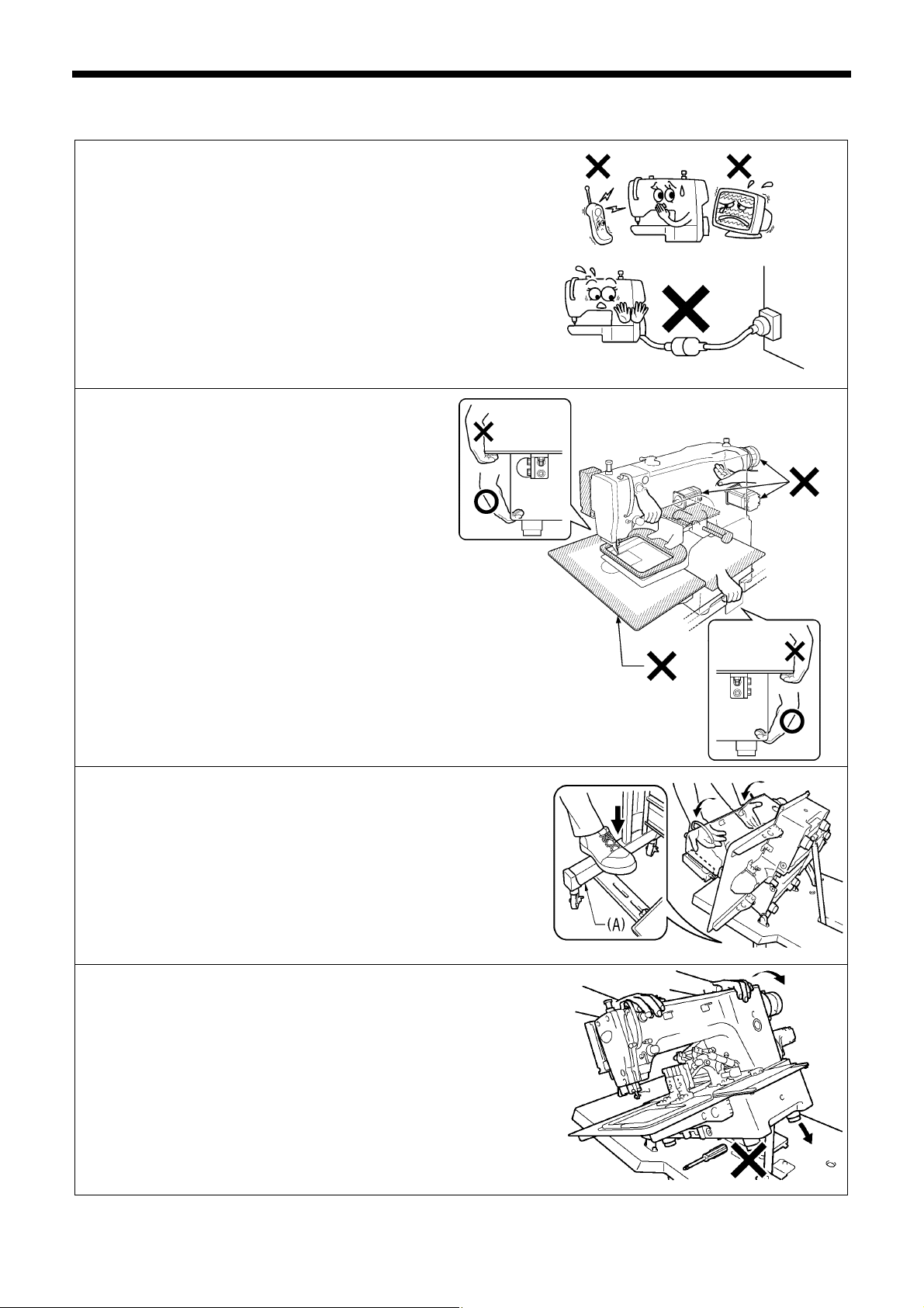
2. NOTES ON HANDLING
About the machine set-up location
・ Do not set up this sewing machine near other equipment
such as televisions, radios or cordless telephones,
otherwise such equipment may be affected by electronic
interference from the sewing machine.
・ The sewing machine should be plugged directly into an
AC wall outlet. Operation problems may result if
extension cords are used.
Carrying the machine
・ The machine should be carried by the arm by
two people as shown in the illustration.
・ When holding the machine head, do not hold it
by the motor, otherwise it may damage the
motor.
・ Do not hold the shaded parts, as they can bend
easily.
2. NOTES ON HANDLING
2516B
3243B
Tilting back the machine head
1. Pack away any tools which are near the table.
2. Secure the foot (A) so that the table will not move, and
then pull the arm with both hands to tilt back the machine
head.
* While supporting the arm with both hands, gently lower it.
Returning the machine head to the upright position
1. Pack away any tools which are near the table.
2. While supporting the arm with both hands, gently return
the machine head to its original position.
3244B
3245B
BAS-311H
2
Page 12
3. FUNCTION SETTINGS
3. FUNCTION SETTINGS
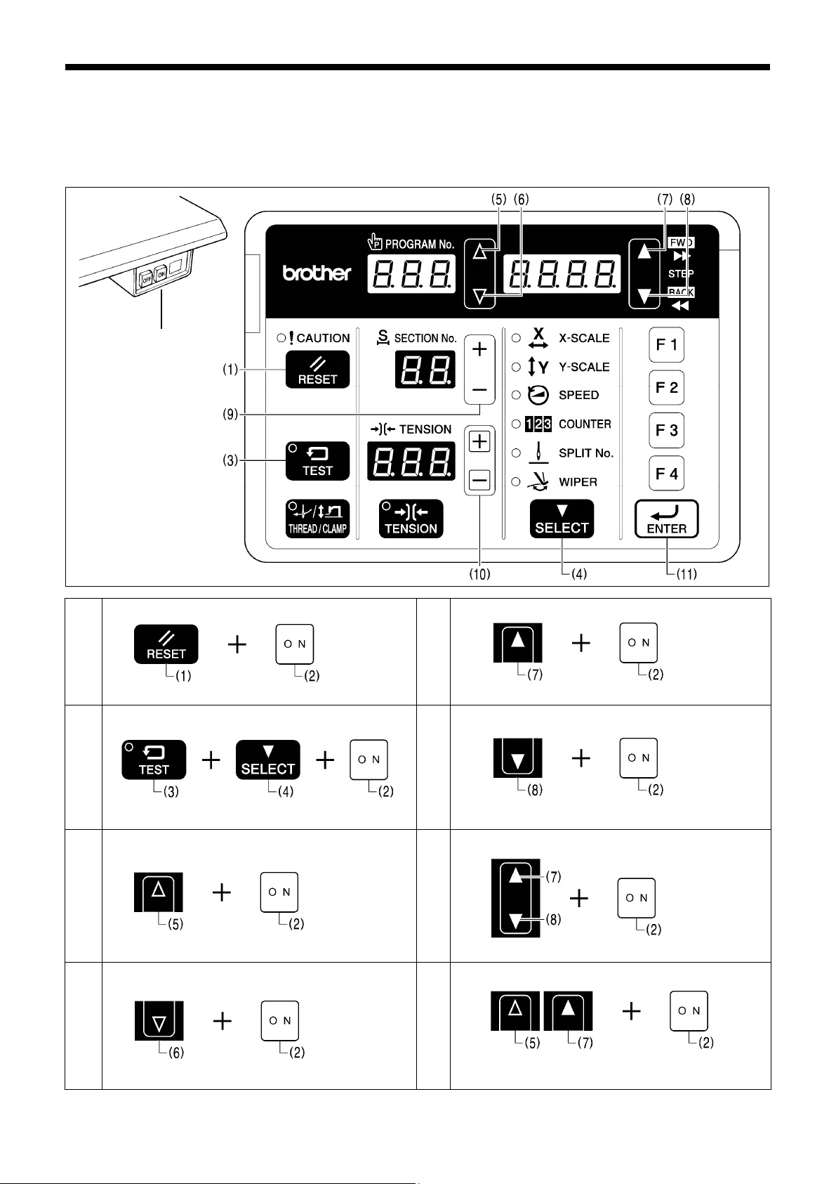
3-1. List of special functions when power is turned on
This list shows the key operations for using special functions.
3055B
(2)
3193B
Data initialization function
1
Refer to the CD Instruction Manual.
Memory switch setting mode (Advanced)
2
Refer to “3-3. Setting memory switches (Advanced)”.
Input check function
3
Refer to “3-7. Input checking method”.
Output check function
4
Refer to “3-8. Output checking method”.
3
2595B
2596B
2597B
2598B
BAS-311H
Software version display function
5
Refer to “3-9. Confirming software version”.
Error log display function 2600B
6
Refer to “3-6. Error history checking method”.
Home position adjusting mode
7
Refer to “8-22. Adjusting the home position”.
Treadle position adjustment mode 2602B
8
Refer to “ 8 -25. Setting method for standard
depression strokes (Foot switch)”.
2599B
2601B
Page 13
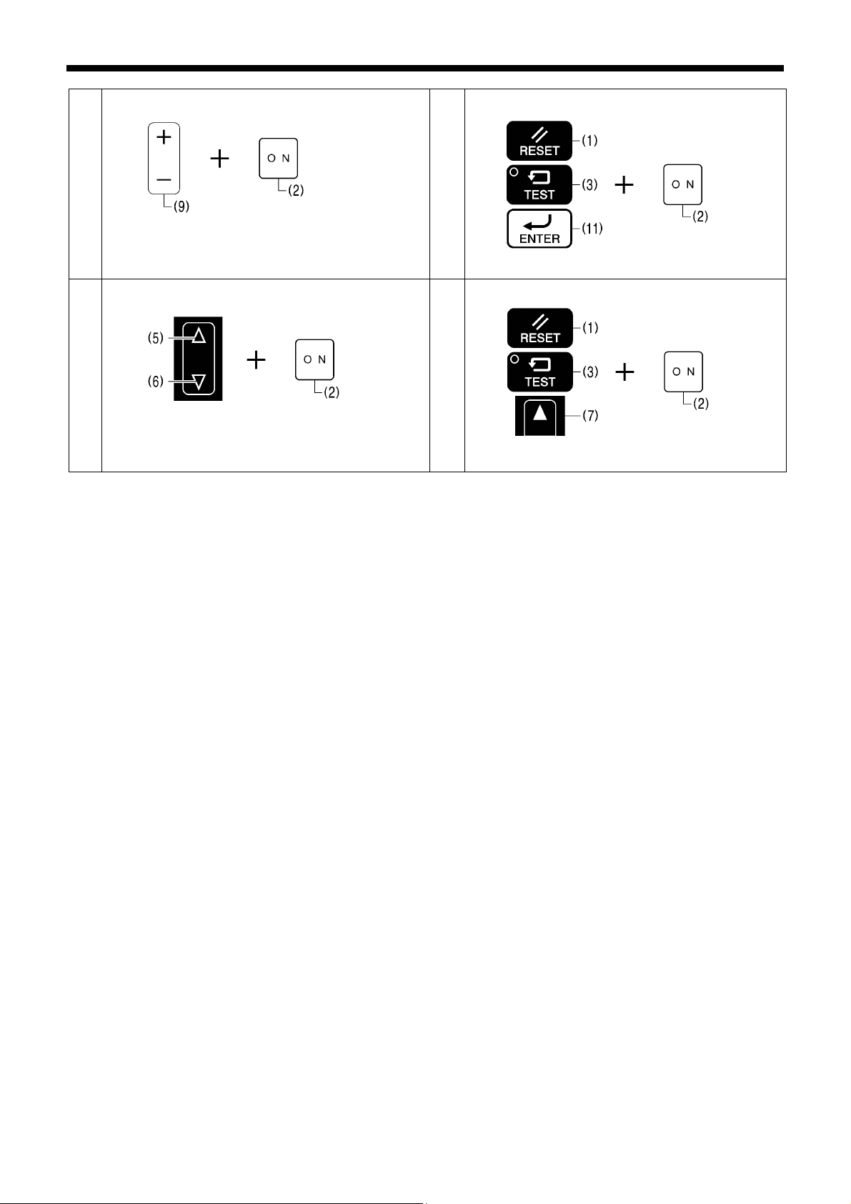
Motor standard position adjustment mode
9
Refer to “8-23. Adjusting the motor standard position”.
Needle up stop position adjustment mode 3194B
10
Refer to “8-24. Adjusting the needle up stop position”.
2603B
3. FUNCTION SETTINGS
Protect setting mode 2605B
11
Refer to “3-10. Protection settings”.
Version update 2606B
12
Refer to “5-13. Updating the control program version”.
BAS-311H
4
Page 14
3. FUNCTION SETTINGS
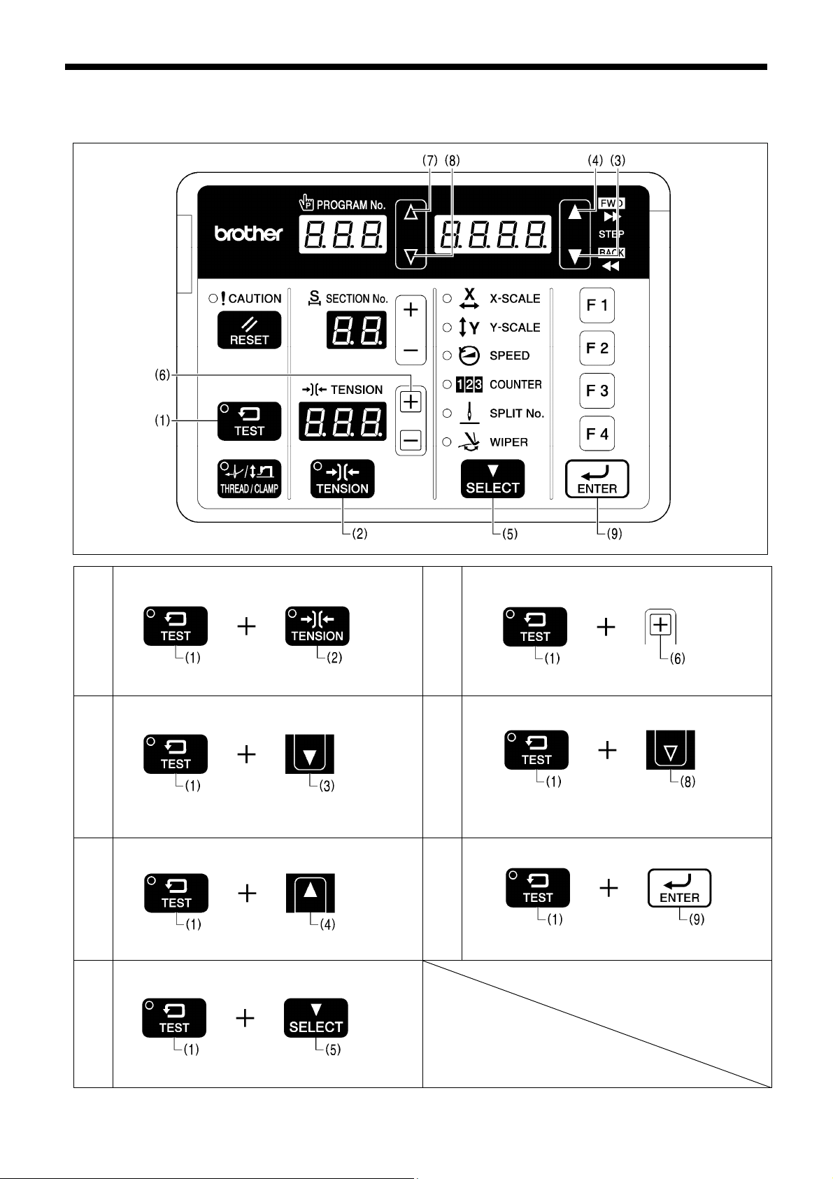
3-2. List of advanced functions
This list shows the key operations for using advanced functions.
Memory switch setting mode (Standard)
1
Refer to the CD Instruction Manual.
Lower thread counter setting mode
2
Refer to the CD Instruction Manual.
Production counter setting mode
3
Refer to the CD Instruction Manual.
Program mode
4
Refer to the CD Instruction Manual.
2608B
2609B
2610B
2611B
Cycle program setting mode 2612B
5
Refer to the CD Instruction Manual.
Parallel movement mode
6
Refer to “4. X and Y parallel movement of sewing
SD data read/write mode
7
Refer to “5-3. Preparation for reading and writing data”.
3195B
2614B
patterns”.
2615B
5
BAS-311H
Page 15
A
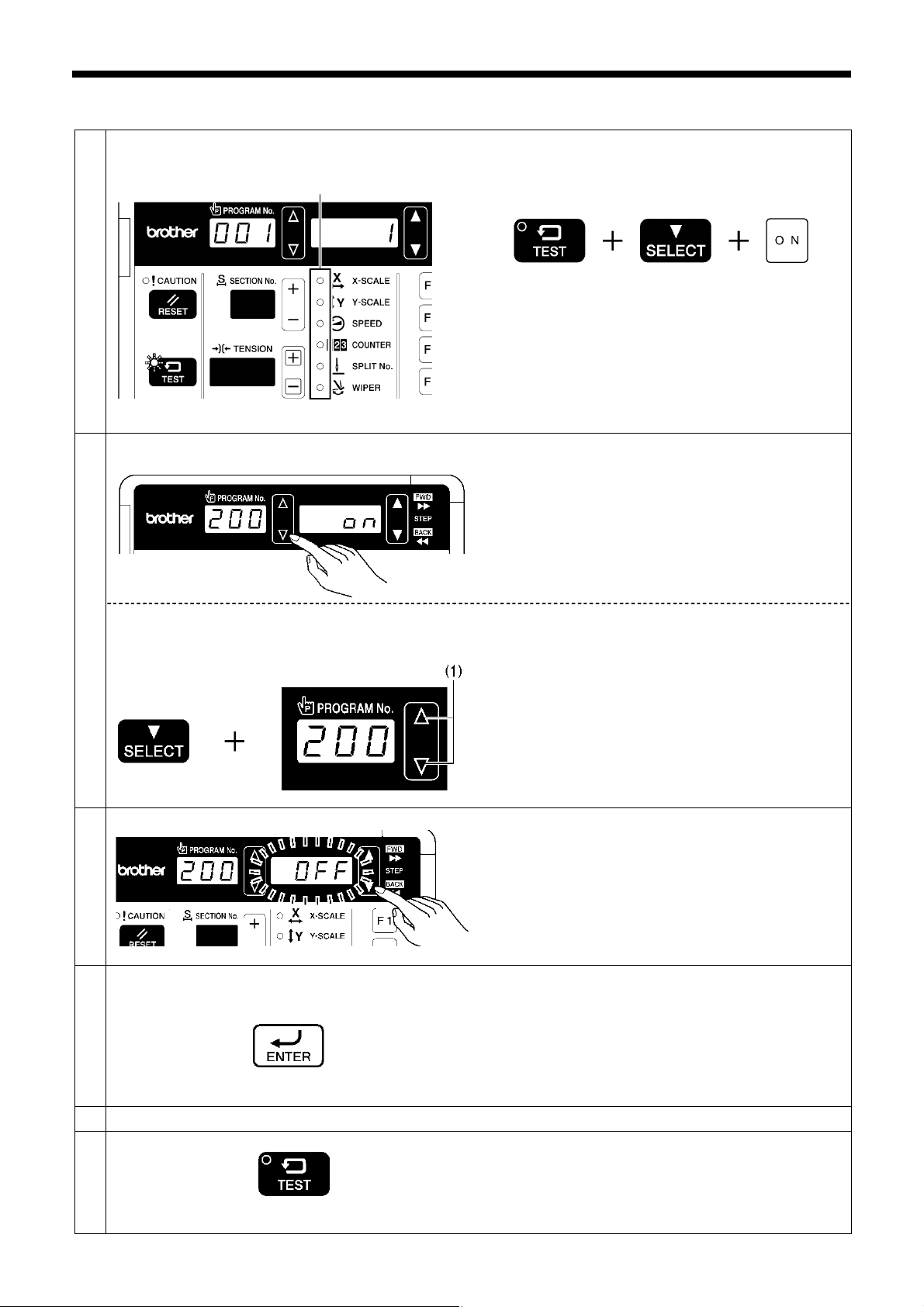
3-3. Setting memory switches (Advanced)
Change the mode to memory switch setting mode.
1
ll indicators switch off
While pressing the TEST key and the SELECT key,
turn on the power switch.
・ The memory switch number will be displayed in the
Select the memory switch that you would like
2
to change the setting for.
Press the △ or ▽ key to select the memory switch
number.
3. FUNCTION SETTINGS
PROGRAM No. display and the setting value for that
number will be displayed in the menu display.
3196B 2616B
If you would like to display only the numbers of
memory switches that have been changed from
default settings
Change the memory switch setting.
3
Apply the changed setting.
4
Repeat steps 2 to 4 above to set each memory switch.
5
Exit setting mode
6
TEST indicator switches off
2414B
While pressing the SELECT key, press the △ or ▽ key
(1).
・ The numbers of memory switches that have been
changed from default settings will appear in order.
Press the ▲ or ▼ key to change the setting value.
・ The flashing display means that the setting has not yet
been applied.
・
You can make the initial setting appear in the display
by pressing the RESET key.
Press the ENTER key.
The menu display will change from flashing to
・
illuminated,
has been applied.
・
If you press the △ or ▽ key (1) or the TEST key
without pressing the ENTER key, you can cancel the
parameter changes.
Press the TEST key.
and this means that the parameter setting
・ The changes will be memorized and the sewing
machine will switch to home position detection
standby.
3210B
2423B
3197B
2404B
BAS-311H
6
Page 16
3. FUNCTION SETTINGS
3-4. List of memory switches
Initial
value
OFF
Lo4
OFF None
OFF None
OFF None
OFF None
ON None
Specification
limits
2 None
0
Pneumatic
2
0 None
Solenoid
None
*1
Setting
range
ON/OFF
No.
001 0-2
002 0-2
003 0-2
100 ON/OFF
200 ON/OFF
300 ON/OFF
400 ON/OFF
402 ON/OFF
403 0-1
405
7
Settings Setting details
Work clamp lift timing after sewing is completed
0
Work clamp is not raised automatically.
Work clamp is raised at the final stitch position.
* Disabled when memory switch No. 71 is set to “2”, or when
1
2
Work clamp lowering sequence for separate work clamp
(Pneumatic work clamp specifications only)
0
1
2
Work clamp lowering operation (Motor-driven work clamp specifications only)
0
1
2
Slow start method
OFF
ON
Single-stitch test feed
OFF
ON
Production counter display
OFF Lower thread counter display
ON Production counter display
Sewing condition detail settings
OFF Parameters which are common to all programs are used.
ON Parameters can be set separately for each program.
Unit display for pattern zoom ratio
OFF Displayed as %
ON Displayed as mm
Split mode selection
0 Continuous split mode
1 Single split mode
Cycle program No. (C01 to C30) display
OFF Disabled (Skipped)
ON Enabled
memory switch No. 72 is set to “2”.
Work clamp is raised after moving to the home position.
* Disabled when memory switch No. 71 is set to "2", or when
memory switch No. 72 is set to "2".
Left and right work clamps are lowered at the same time.
Work clamp is lowered in the order left → right.
Work clamp is lowered in the order right → left.
Analog lowering: Work clamp is lowered in direct proportion to the
pedal depression amount, and sewing starts when the pedal is fully
depressed.
* This operation is only possible for foot switch specifications; for
two-pedal foot switch specifications, operation is the same as for a
2-step work clamp.
1-step work clamp: Work clamp is lowered when pedal is depressed
to the 1st step, and sewing starts when pedal is depressed to the
2nd step.
2-step work clamp: Work clamp is lowered to intermediate height
when pedal is depressed to the 1st step, and work clamp is fully
lowered and sewing starts when the pedal is depressed to the 2nd
step.
The sewing speed for the first 5 stitches will be in accordance with
the setting for memory switch Nos. 151 to 155.
The sewing speed for the first 5 stitches can be selected from the
nine slow start patterns “Lo1” to “Lo9”. (Refer to the CD Instruction
Manual.)
Test feed starts when the foot switch (start switch) is depressed, and
it continues automatically until the final stitch.
Test feed starts when the foot switch (start switch) is depressed, and
it moves forward by one stitch each time the switch is depressed.
In addition, when the TEST indicator is flashing, test feed will move
forward one stitch at a time when the machine pulley is turned by
hand.
BAS-311H
Page 17

3. FUNCTION SETTINGS
No.
406
*2
407
408
409
410
Setting
range
0-2
Settings Settings details
F key specifications
0
1
F keys become direct selection keys for sewing program numbers
(101 to 104).
F keys become direct selection keys for cycle program numbers
(C01 to C04).
* Selection is possible when memory switch No. 400 is set to “ON”.
F keys become shortcut keys for program numbers which have been
assigned to the keys.
2
Assignment number to F1 key
100-999, C01-C30
Assignment number to F2 key
100-999, C01-C30
Assignment number to F3 key
100-999, C01-C30
Assignment number to F4 key
100-999, C01-C30
F1 … Setting number for memory switch No. 407
F2 … Setting number for memory switch No. 408
F3 … Setting number for memory switch No. 409
F4 … Setting number for memory switch No. 410
Initial
value
101 None
102 None
103 None
104 None
Specification
limits
0 None
*1: If there are no valid sewing programs when memory switch No. 405 is set to "OFF", only the standard program numbers
are displayed. If it is set to "ON" when no programs have been registered, nothing is displayed (the display is skipped).
*2: If an F key which does not have a program registered to it is pressed, the key will be invalid. (The buzzer will sound
twice.)
BAS-311H
8
Page 18

3. FUNCTION SETTINGS
Work clamp settings
No.
051 ON/OFF
052 ON/OFF
053 0-999
054 0-2
055 0-2
056 ON/OFF
057 ON/OFF
059 0-1
060 0-3000
Setting
range
Settings Settings details
Work clamp operation before home position detection
OFF
ON
Work clamp operation during split programs
OFF
ON
Time from intermittent presser foot lifting until feed mechanism starts moving
Intermittent presser foot drop timing
0
1
2
Work clamp signal valve special output for pneumatic-type work clamp
0
1
2
Thread winding operation before home position is detected
OFF
ON
Work clamp operation when feed moves to sewing start position after home
position is detected
OFF
ON
Operation settings for heavy-weight materials
0
1
Time after the work clamp drops until the shaft starts rotating.
Work clamp cannot be raised or lowered before home position is
detected.
Work clamp can be raised and lowered before home position is
detected.
Work clamp lifts automatically when sewing pauses due to a split
program.
Work clamp does not lift automatically when sewing pauses due to a
split program.
Units (ms), Increments of 1
Presser foot drops when the work clamp switch is depressed, but it
does not drop at the retract position.
Presser foot drops when the work clamp switch is depressed.
Presser foot drops at the sewing start, regardless of the work clamp
switch operation.
Disabled
Valve output is reversed for pneumatic-type work clamp
specifications.
(Connect the air tubes in reverse so that the work clamp can lift
when the power is turned off.)
Reverse valve output for pneumatic specifications is output
simultaneously for 2-position valve specifications.
(Right work clamp reverse = Option output No. 4: Left work clamp
reverse = Option output No. 5)
Thread winding cannot be carried out before home position is
detected.
Thread winding can be carried out before home position is detected.
Work clamp stays dropped after home position is detected.
Work clamp lifts when work clamp switch is depressed (when
depressed backward for foot switch).
Work clamp lifts automatically after home position is detected.
Standard
When using a heavy work clamp and feed plate
(Maximum sewing speed is limited to 2,200 sti./min.)
Units (ms), Increments of 10
*1
Initial
value
ON None
OFF None
100 None
OFF None
ON
Specification
limits
0 None
0
Pneumatic
None
0
Pneumatic
0 None
*1: If memory switch No. 051 is set to "OFF", thread winding is not possible before home position detection is carried out.
Thread winding is not possible during intermittent lifting and before work clamp home position detection is carried out
(such as when the work clamp switch has not been depressed at all after the power was turned on), even when memory
switch No. 056 is set to "ON".
9
BAS-311H
Page 19
Pedal type and work clamp operation settings
3. FUNCTION SETTINGS
No.
070 1-3
071 1-3
072 1-7
Setting
range
Settings Settings details
Pedal specifications (Not reset during initialization)
Foot switch
1
2
3
Work clamp operation when foot switch is set
(Can be set when memory switch No. 70 is set to "1". Not displayed at other
times.)
(Not reset during initialization)
1 [Standard]
2
3
(Memory switch No. 71 can be set, and memory switch Nos. 72 and
73 are not displayed.)
Two-pedal foot switch
(Memory switch No. 72 can be set, and memory switch Nos. 71 and
73 are not displayed.)
Three-pedal foot switch
(Memory switch No. 73 can be set, and memory switch Nos. 71 and
72 are not displayed.)
[No automatic work clamp lifting]
Work clamp lifts when pedal is depressed backward.
[2-step work clamp using two presses]
When work clamp switch is depressed: (1st step) Drop → (2nd step)
Drop (skipped for single step work clamp) → Start
When depressed backward = Both work clamps lift
* Operates as a 2-step work clamp when memory switch No. 003 is
set to "0".
Work clamp operation when two-pedal foot switch is set
(Can be set when memory switch No. 70 is set to "2". Not displayed at other
times.)
(Not reset during initialization)
[Standard]
Work clamp lifts automatically and drops when the work clamp
1
2
3
4
5
switch is depressed.
The left and right order can be changed using memory switch No.
002.
[No automatic work clamp lifting]
Work clamp lifts while work clamp switch is being depressed.
[Left/right work clamp → intermittent presser foot 2-step work clamp]
When work clamp switch is depressed to the 1st step, both the left
and right work clamps are lowered, and when it is depressed to the
2nd step, the intermittent presser foot is lowered.
Lifting is in the same order.
[Left and right alternating 2-step work clamp]
2-step operation, with left and right order switching for each item
sewn.
Starts from right.
[Forward/reverse pedal]
When the start switch is depressed, the work clamp drops and the
sewing machine starts in that order with forward control, and when
the work clamp switch is depressed, the sewing machine reverses
and the work clamp lifts.
* The left and right order can be changed using memory switch No.
002.
[2-step work clamp using two presses]
When the work clamp switch is depressed, the left work clamp drops
6
→ Right work clamp drops → Both work clamps lift in that order
* The left and right order can be changed using memory switch No.
002.
[Work clamp drops and sewing starts only when work clamp switch is
depressed]
7
Work clamp drops and sewing starts only by depressing the work
clamp switch.
* Starting sewing is also possible by using the start switch.
Initial
value
1
(Solenoid)
2
(Pneumatic)
1
1
Specification
limits
None
None
None
Solenoid
None
None
Pneumatic
Pneumatic
Pneumatic
Pneumatic
None
BAS-311H
10
Page 20

3. FUNCTION SETTINGS
No.
Setting
073 1-3
range
Settings Settings details
Work clamp operation when three-pedal foot switch is set
(Can be set when memory switch No. 70 is set to "3". Not displayed at other
times.)
(Not reset during initialization)
1
2
3
[Standard]
Pneumatic method: The left pedal raises and lowers the left work
clamp, and the right pedal (center) raises and lowers the right work
clamp.
The start switch (right) starts the sewing machine.
Motor-driven method (Solenoid) : 1st step when left pedal is
depressed: 2nd step when right (center) pedal is depressed (invalid
for single step work clamp)
The start switch (right) starts the sewing machine.
[Independent home detection]
The right pedal (center) is used exclusively for detecting the home
position.
The left pedal raises and lowers the left and right work clamps, and
the start pedal (right) starts the sewing machine.
The start switch (right) starts the sewing machine.
[Independent home detection]
The right pedal (center) is used exclusively for detecting the home
position.
The left work clamp only is raised and lowered when the left pedal is
depressed.
The start switch (right) lowers the right work clamp and starts the
sewing machine.
Initial
value
1
Specification
limits
None
Pneumatic
Pneumatic
11
BAS-311H
Page 21

Upper shaft motor settings
3. FUNCTION SETTINGS
*1
*1
*1
*1
*1
Setting
range
200-2800
200-2800
200-2800
200-2800
200-2800
1200-
2800
No.
150 ON/OFF
151
152
153
154
155
156 200-2800
157 200-2800
158 200-2800
159 200-2000
161 ON/OFF
162 ON/OFF
163
164 ON/OFF
Settings Settings details
Highest needle position stop (When set to "ON", memory switch Nos. 165 and
166 can be set.)
OFF
When the upper shaft motor stops, the motor operation reverse to
return the needle bar close to its highest position.
* When the motor operates in reverse to raise the needle, the thread
ON
1st stitch sewing speed at the sewing start
2nd stitch sewing speed at the sewing start
3rd stitch sewing speed at the sewing start
4th stitch sewing speed at the sewing start
5th stitch sewing speed at the sewing start
Sewing speed for 5th stitch before the sewing end
Sewing speed for 4th stitch before the sewing end
Sewing speed for 3rd stitch before the sewing end
Sewing speed for 2nd stitch before the sewing end
Piercing force boosting operation
OFF
ON
Regulation of sewing speed changes due to sewing pitch changes
OFF
ON
The maximum value is limited when the sewing speed is set using the menu.
It is applied to the panel speed display.
The maximum values are limited for all speed setting values which have been
programmed.
Thread trimming disabled
OFF
ON
take-up will stop at a position which is lower than its normal
stopping position. As a result, the thread take-up will rise slightly at
the sewing start, and this may result in the thread pulling out under
certain conditions.
Units ( sti./min ), Increments of 100
Units ( sti./min ), Increments of 100
Units ( sti./min ), Increments of 100
Units ( sti./min ), Increments of 100
Units ( sti./min ), Increments of 100
Units ( sti./min ), Increments of 100
Units ( sti./min ), Increments of 100
Units ( sti./min ), Increments of 100
Units ( sti./min ), Increments of 100
Disabled
Enabled (Piercing force boosting operations are carried out when the
sewing machine motor is locked.)
Sewing speed varies depending on sewing pitch of the sewing data.
Speed is fixed at the minimum sewing speed for the maximum pitch
of the sewing data.
(Set to “ON” if there may be a problem with sewing speed changes
as a result of pitch changes.)
Units (sti./min), Increments of 100
Thread trimming is carried out in accordance with the sewing data.
Thread trimming is not carried out.
Initial
value
OFF
400
800
1200
2800
2800
2800
2800
2800
1200
OFF
OFF
2800
OFF
Specification
limits
None
None
None
None
None
None
None
None
None
None
None
None
None
None
BAS-311H
12
Page 22

3. FUNCTION SETTINGS
No.
165 -20-20
166 10-500
167 ON/OFF
168 0-120
169 30-89
170 0-2800
171 ON/OFF
Setting
range
Settings Settings details
Stop position settings at highest needle position stop
(Can only be set when memory switch No. 150 is set to "ON", not displayed at
other times.)
Delay time until reverse operation starts during highest needle position stop
operation
(Can only be set when memory switch No. 150 is set to "ON", not displayed at
other times.)
Servo lock enabled or disabled setting
(When set to "ON", memory switch Nos. 168 and 169 can be set.)
OFF
ON
Servo lock timer setting
(Can only be set when memory switch No. 167 is set to "ON", not displayed at
other times. If it is set to “0”, no timer operation.)
Servo lock release rotation angle
(Can only be set when memory switch No. 167 is set to "ON", not displayed at
other times.)
Lowers the allowable speed for the sewing pitch by the amount set.
Automatic needle lifter operation
OFF
ON
Needle bar height increases for values in the negative direction.
Units (degree), Increments of 1
Units (ms), Increments of 10
Disable
Enable
Units (s), Increments of 1
Units (degree), Increments of 1
Overall speed reduction (sti./min) Increments of 100
However, the minimum allowable speed value is 400 sti./min.
Does not operate automatically, and a needle up stop position error
is generated.
(When memory switch No. 655 is set to "ON", the sensor can also
be ignored.)
If the needle bar is not at the needle up stop position during feeding
or work clamp home position detection, it moves automatically to the
needle up stop position.
Initial
value
150 None
OFF None
45 None
ON None
Specification
limits
0 None
0 None
0 None
*1: Only enabled when memory switch No. 100 is set to "OFF".
13
BAS-311H
Page 23
Feed settings
3. FUNCTION SETTINGS
No.
250 ON/OFF
251 1-5
252
*1
253 0-2
254 0-3
255 ON/OFF
260 -80-80
Setting
range
ON/OFF
Settings Settings details
Mechanism home position return when sewing is finished
OFF When sewing is finished, the feed returns to the start position.
ON
The speed of the feeding operation
High-speed test feed method
OFF
ON High-speed feeding starts at the same time test feeding starts.
Moving method to the start point (Not reset during initialization)
*2
Movement path from mechanism home position to start position (Not reset
during initialization)
Y-feed full stroke movement operation
OFF
ON
Changes the overall feed timing (-80 Early ←→80: Late)
When sewing is finished, the feed moves via the machine home
position to the start position.
1 Slow 100 mm/s
2 200 mm/s
3 300 mm/s
4 400 mm/s
5 Fast 500 mm/s
Normally slow, but becomes faster when the foot switch is
depressed to the 1st step.
(For a two-pedal foot switch, when the work clamp switch is
depressed.)
Depress the foot switch to the 2nd step while the program number is
0
flashing.
(For a two-pedal foot switch, depress the start switch.)
When the RESET key is pressed while the program number is
flashing:
When work clamp is lowered before moving to sewing start
position → Moves to sewing start position
When work clamp is lowered after moving to sewing start position
→ Ignored
When work clamp is raised before moving to sewing start position
→ Work clamp is lowered + Moves to sewing start position
When work clamp is raised after moving to sewing start position →
Ignored
When the expansion input switch (EXIN3) is pressed while the
program number is flashing:
When work clamp is lowered before moving to sewing start
position → Moves to sewing start position
When work clamp is lowered after moving to sewing start position
→ Ignored
When work clamp is raised before moving to sewing start position
→ Ignored
When work clamp is raised after moving to sewing start position →
Ignored
No route specified
Moves in the order X→Y when moving to the home position, and in
the order Y→X when moving to the sewing start position.
Moves in the order Y→X when moving to the home position, and in
the order X→Y when moving to the sewing start position.
Operates while avoiding the center of the clamped area.
Y-feed full stroke movement operation does not occur when home
position detection is carried out immediately after the power is
turned on.
Y-feed full stroke movement operation occurs when home position
detection is carried out immediately after the power is turned on.
Units (degree), Increments of 1
1
2
0
1
2
3
Initial
value
OFF None
OFF None
ON None
Specification
limits
3 None
0 None
0 None
0 None
*1: Only enabled when memory switch No. 200 is set to "OFF".
*2: The start switch is disabled. Cannot be set when memory switch No.650 is set to "2".
BAS-311H
14
Page 24

3. FUNCTION SETTINGS
No.
Setting
range
261 -80-80
262 -80-80
263 -80-80
264 -80-80
265 -80-80
266 -80-80
267 0-99
268 0-3
269 0-2
270 0-3
Settings Setting details
Changes the feed timing for the 1st stitch at the sewing start
(-80 Early ←→80: Late)
Changes the feed timing for the 2nd stitch at the sewing start
(-80 Early←→80: Late)
Changes the feed timing for the 3rd stitch at the sewing start
(-80 Early ←→80: Late)
Changes the feed timing for the 3rd stitch before the sewing end
(-80 Early←→80: Late)
Changes the feed timing for the 2nd stitch before the sewing end
(-80 Early ←→80: Late)
Changes the feed timing for the 1st stitch before the sewing end
(-80 Early ←→80: Late)
When the overall feed timing has been changed using memory switch No. 260,
this specifies the effective number of stitches.
0
1-99
Changes the overall feed timing reference
0
1
2
3
Changes the feed timing reference for the first three stitches at the sewing start
0
1
2
Home position detection operation when the program is changed
0
1
2
3
Units (degree), Increments of 1
Units (degree), Increments of 1
Units (degree), Increments of 1
Units (degree), Increments of 1
Units (degree), Increments of 1
Units (degree), Increments of 1
No limit
When the specified number of stitches is exceeded, the feed timing
returns to the standard timing.
[Feed start reference] Makes the timing uniform at the start of feed.
[Needle up reference] Changes the timing at the start of feed so that
the needle zigzagging is even.
[Feed end reference] Makes the timing uniform at the end of feed.
[Linked to speed] Feed timing is uniform even if the sewing speed
changes.
[Feed start reference] Makes the timing uniform at the start of feed.
[Needle up reference] Changes the timing at the start of feed so that
the needle zigzagging is even.
[Feed end reference] Makes the timing uniform at the end of feed.
Home position detection is not carried out.
Moves to sewing start position when start switch is depressed, and
then stops.
Home position detection is not carried out.
Moves via the center of the sewing area to the sewing start position
when start switch is depressed, and then stops.
Home position detection is carried out.
Moves to sewing start position after home position detection when
start switch is depressed, and then stops.
Home position detection is not carried out.
If the program has changed, moves to the next sewing start position
and then stops.
Initial
value
Specification
limits
0 None
0 None
0 None
0 None
0 None
0 None
0 None
1 None
1 None
0 None
15
BAS-311H
Page 25

Panel operation settings
3. FUNCTION SETTINGS
No.
352 0-2
353 ON/OFF
354 0-9
355 ON/OFF
Setting
range
Settings Setting details
Counting method for production counter and lower thread counter
0
Counted for each item of sewing data.
1
Counted for each thread trimming operation.
2
Counted when sewing data ends or when split stops.
Counter timing for lower thread counter
OFF
ON
Switching program numbers using an external switch
1-9
Switches split numbers using an external switch
OFF
ON
Counted at the end of sewing.
Counted at the start of sewing.
0
Disable
Program number is switched by means of the 5 bits of option input
(EXIN6 − EXIN10).
* Applicable numbers are: Setting number = 3rd digit, last two digits
can be 1 − 31.
Disable
Split number is switched by means of the 5 bits of option input
(EXIN6 − EXIN10).
* Applicable numbers are 1 − 31 (only enabled for independent split
mode).
Initial
value
OFF None
OFF None
Specification
limits
0 None
0 None
BAS-311H
16
Page 26

3. FUNCTION SETTINGS
Program settings
No.
460 0-150
461 0-100
462 0-8
465 1-3
468 ON/OFF
Setting
range
Settings Setting details
X-sewing area setting (Not reset during initialization)
Units (mm), Increments of 1
Y-sewing area setting (Not reset during initialization)
Units (mm), Increments of 1
Enlargement/reduction reference point
0
Zoom reference point is the center of the sewing frame.
1
Zoom reference point is the sewing start position.
2
Zoom reference point is the center of the sewing pattern.
3
Front of pattern center
4
Back of pattern center
5
Back-left corner of sewing area
6
Front-left corner of sewing area
7
Back-right corner of sewing area
8
Front-right corner of sewing area
Movement amount is Initialized when program number or
1
enlargement/reduction ratio is changed and when power is turned
off.
Movement amount is Initialized when program number or
2
enlargement/reduction ratio is changed but not when power is
turned off.
Set separately for each program.
* Disabled when memory switch No. 400 is set to "OFF".
3
(Parallel movement mode cannot be used.)
The parallel movement amount is stored even when the power is turned off.
* Select "1" or "2" when memory switch No. 400 is set to "OFF".
Retract point switching at parallel movement point
OFF
ON
Disable
The position moved to by parallel movement is recorded as the
retract point.
Initial
value
150 None
100 None
OFF None
Specification
limits
0 None
1 None
17
BAS-311H
Page 27
Device settings
3. FUNCTION SETTINGS
No.
550 0-2000
551 0-3
552 -80-8
554 ON/OFF
555 ON/OFF
556 0-3
557 0-2
558 ON/OFF
559 ON/OFF
560 0-3
Setting
range
Settings Setting details
Needle cooler device
0
Disable
Needle cooler device is used.
Continuous output time after sewing machine stops (ms)
Increments of 100
0
0
0
1
2
3
0
1
2
Not released
Released during the specified number of stitches
-3: Medium-weight material specifications
-5:
Heavy-weight material specifications
-7: Seatbelt specifications
Disable
Fiber-type thread breakage sensor is used.
5 stitches at sewing start, 3 stitches while sewing
10 stitches at sewing start, 3 stitches while sewing
Disable
Inner clamping device is used.
(Retract operation is carried out at the sewing end to prevent
interference with the needle.)
Inner clamping device is used.
(No retract operation at the sewing end)
Inner clamping device operates for 1/4 of the sewing pattern and
returns for the other 3/4.
(No retract operation)
Disable
Standard wiper device is used.
Pneumatic-type wiper device is used. (Option output No. 2)
Disable
Enabled (Option input No. 13 [AIRSW])
Disable
Option output No. 9 : Output ON while operating
Option output No. 10: ON during lower thread conversion and during
test mode
Option output No. 11: ON when error is generated
100-
2000
Upper thread tension release at the sewing start
1-3
Tension release timing during thread trimming
-24
Thread breakage sensor
OFF
ON
Thread breakage sensor detection sensitivity
OFF
ON
Inner clamping device (Option output No.13) (Not reset during initialization)
Wiper device
External error monitoring input
OFF
ON
Operating indicator output
OFF
ON
Automatic ejector
(Option output No. 3 output: Option input No. 1 = right sensor: Input No. 2 = left
sensor)
* When this device is used, memory switch No. 002 should be set to "0".
0
Disable
1
Standard automatic ejector operation occurs.
2
Sewing starts when cassette sensor is ON.
3
Start switch is enabled even if cassette sensor is OFF.
0
0
0
0
1
0
Specification
limits
None
None
None
None
None
None
None
None
Pneumatic
Initial
value
(-3,-5)
-24
(-7)
OFF None
OFF
OFF
OFF
BAS-311H
18
Page 28

3. FUNCTION SETTINGS
No.
561 0-999
564 ON/OFF
565 0-2
567 ON/OFF
569 0-3
570 1-99
571 1-99
572 1-99
Setting
range
Settings Setting details
Time from sensor turning on to sewing start when memory switch No. 560 is set
to "2"
2-step tension
OFF
ON
Tension release force setting
0
1
2
Upper thread tension during test feed
OFF
ON
Detection timing for lower thread sensor (Not reset during initialization)
Wait time after lower thread detection is complete
Wait time for lower thread detection response
Output time for lower thread detection operation command signal
Units (ms), Increments of 1
Disable
2-step tension is used.
Standard
(Tension release is open at the sewing end.)
Increases the force.
(Tension release is closed at the sewing end. When using threading
mode, it will be closed in approximately 5 minutes.)
Tension release force is set to the maximum.
(Tension release is closed at the sewing end. When using threading
mode, it will be closed in approximately 1 minute.)
Upper thread tension not applied.
Upper thread tension applied.
0: Sensor not used = 1: Before = 2: After = 3: Before and after
Units (×10 ms), Increments of 1
Units (×10 ms), Increments of 1
Units (×10 ms), Increments of 1
Initial
value
100
OFF None
(-3,-5)
(-7)
OFF None
30 None
30 None
50 None
Specification
limits
Pneumatic
0
1
0 None
None
19
BAS-311H
Page 29

Error processing settings
3. FUNCTION SETTINGS
No.
650 0-2
651 0-2
652 ON/OFF
653 ON/OFF
655 ON/OFF
656 ON/OFF
657 0-30
Setting
range
Settings Setting details
Error release method when operation has stopped (Not reset during
initialization)
0 Press the RESET key on the operation panel to release errors.
1 Press the RESET key or the STOP key to release errors.
Press the RESET key or input a signal from the expansion input
2
Needle up stop when operation is paused
0
1
2
Thread trimming operation prevention when sewing is paused
OFF Thread trimming is carried out when the pause is canceled.
ON Thread trimming is not carried out when the pause is canceled.
Resuming sewing after sewing is paused
OFF STOP switch → RESET key →▼ key → Sewing starts
ON STOP switch → RESET key → Sewing starts
Disables needle up stop position monitoring sensor
OFF Sensor enabled (“UP” will be displayed)
ON Sensor disabled
Home position return when sewing is paused
OFF
ON
Time from error occurring to buzzer stopping
0 Buzzer does not stop.
2-30 Units (s), Increments of 2
switch (EXIN3) to release errors.
Cannot be set when memory switch No. 253 is set to "2".
Stops at the needle down position when sewing is interrupted by the
STOP key.
Stops at the needle up position when sewing is interrupted by the
STOP key.
Stops at the needle up position after thread trimming when sewing is
interrupted by the STOP key.
(Thread trimming cannot be set when memory switch No. 652 is set
to "0".)
Mechanism moves to home position and then moves to sewing start
position.
Mechanism steps back to the sewing start position along the sewing
path without moving to the home position.
Initial
value
OFF None
OFF None
OFF
(-3,-5)
ON
(-7)
OFF None
Specification
limits
0 None
0 None
None
0 None
BAS-311H
20
Page 30

3. FUNCTION SETTINGS
Maintenance settings
No.
750 0-3
751 0-3000
752 0-99
Setting
range
Settings Setting details
Run-in operation mode
0
1
2
3
Run-in operation stop time
Sewing machine ID code (Sewing data specified on SD card)
Disable
Continuous operation (one work clamp up/down operation per cycle)
occurs while the start switch remains on.
Not raised and lowered when memory switch No. 001 is set to
"OFF".
Continuous operation (two work clamp up/down operations per
cycle) occurs while the start switch remains on.
Not raised and lowered when memory switch No. 001 is set to
"OFF".
Continuous operation (three work clamp up/down operations per
cycle) occurs while the start switch remains on.
Not raised and lowered when memory switch No. 001 is set to
"OFF".
Units (ms), Increments of 10
Folder specified
Initial
value
200 None
Specification
limits
0 None
0 None
21
BAS-311H
Page 31

Specification and destination settings
3. FUNCTION SETTINGS
No.
850 3,5,7
Setting
range
Settings Setting details
Specification code setting (Not reset during initialization)
3 -3: Medium-weight material specifications
5 -5: Heavy-weight material specifications
7 -7: Seatbelt specifications
Unique settings for each model
No.
951 ON/OFF
Setting
range
Settings Setting details
Program number output
OFF
ON
Disable
When the last two digits of the program number are 1 to 15, the
program number is output in 4 bits to option output 4 − 7.
Initial
value
Initial
value
OFF None
Specification
limits
- None
Specification
limits
BAS-311H
22
Page 32

3. FUNCTION SETTINGS
3-5. Setting the work clamp mode
Combinations of memory switch settings can be used to switch the work clamp operating mode to any one of the following
modes.
<Motor-driven work clamp specifications, Foot switch standard operations>
Foot switch operation is set when memory switch No. 070 is set to "1".
Operating mode Memory switch setting
Lowering
operation
Analog lowering
Work clamp
dropping in 1 step
Work clamp
dropping in 2
steps
Automatic work
clamp lifting
Enabled
Disabled Lowered
Enabled
Disabled Lowered
Enabled
Disabled Lowered
After home
position detection
Automatic lift
Lowered
Automatic lift
Lowered
Automatic lift
Lowered
After sewing start 003 071 057 001
Automatic lift
Lowered
Automatic lift
Lowered
Lowered
Automatic lift
Lowered
Automatic lift
Lowered
Lowered
Automatic lift
Lowered
Automatic lift
Lowered
Lowered
0 1 ON 2
0 1 ON 0
0 1 OFF 2
0 1 OFF 0
0 2 - -
1 1 ON 2
1 1 ON 0
1 1 OFF 2
1 1 OFF 0
1 2 - -
2 1 ON 2
2 1 ON 0
2 1 OFF 2
2 1 OFF 0
2 2 - -
<Motor-driven work clamp specifications, Foot switch sequence operations>
Operating mode Memory switch setting
Lowering
operation
Work clamp
dropping in 1 step
Work clamp
dropping in 2
steps
Automatic work
clamp lifting
Enabled
Enabled
After home
position detection
Automatic lift
Lowered
Automatic lift
Lowered
After sewing start
Automatic lift
Lowered
Automatic lift
Lowered
Automatic lift
Lowered
Automatic lift
Lowered
003 071 057 001
1 3 ON 2
1 3 ON 0
1 3 OFF 2
1 3 OFF 0
2 3 ON 2
2 3 ON 0
2 3 OFF 2
2 3 OFF 0
23
BAS-311H
Page 33

<Pneumatic work clamp specifications, two-pedal foot switch standard operations>
Two-pedal foot switch operation is set when memory switch No. 070 is set to "2".
Operating mode Memory switch setting
Work clamp operation
Work clamp lifts
automatically and drops
when the work clamp switch
is depressed.
After home
position
detection
Automatic
lift
Lowered
After
sewing start
Automatic
lift
Lowered
Automatic
lift
Lowered
002 072 057 001
Work clamp
lowering sequence
selection
0 : Left and right
simultaneously
1 : Left → Right
2 : Right → Left
3. FUNCTION SETTINGS
1 ON 2
1 ON 0
1 OFF 2
1 OFF 0
Work clamp rises while work
clamp switch is depressed.
Work clamp switch
1st step : Both left and right
work clamp drop
2nd step : Intermittent
presser foot drops
Lifting is simultaneous
Work clamp drop sequence
at work clamp switch 1st
and 2nd step alternates
each time an article is sewn.
Initially right → left
<Pneumatic work clamp specifications, two-pedal foot switch sequence operations>
Operating mode Memory switch setting
Work clamp operation
When start switch is
depressed, work clamp
drops → sewing starts
Lifts in reverse order using
work clamp switch
Lowered
Automatic
lift
Lowered
Automatic
lift
Lowered
After home
position
detection
Automatic
lift
Lowered
Lowered
Automatic
lift
Lowered
Automatic
lift
Lowered
Automatic
lift
Lowered
Automatic
lift
Lowered
After
sewing start
Automatic
lift
Lowered
Automatic
lift
Lowered
- 2 - -
-
-
002 072 057 001
Work clamp drop
sequence selection
0 : Left and right
simultaneously
1 : Left → Right
2 : Right → Left
3 ON 2
3 ON 0
3 OFF 2
3 OFF 0
4 ON 2
4 ON 0
4 OFF 2
4 OFF 0
5 ON 2
5 ON 0
5 OFF 2
5 OFF 0
Work clamp switch
Left (right) work clamp →
Right (left) work clamp →
Both work clamps lift
Automatic
lift
Lowered
Automatic
lift
Lowered
Automatic
lift
Lowered
Work clamp drop
sequence selection
0 : Left and right
simultaneously
1 : Left → Right
2 : Right → Left
6 ON 2
6 ON 0
6 OFF 2
6 OFF 0
BAS-311H
24
Page 34

3. FUNCTION SETTINGS
3-6. Error history checking method
The past error history can be checked by the following procedure.
3198B
1. While pressing the ▼ key (1), turn on the power switch.
The error history sequence number will be displayed in the PROGRAM No. display (2) and the error code will be
displayed in the menu display (3).
NOTE:
E025, E035, E065, E705 and error codes which can be reset do not remain in the error history, and so they will not be
displayed.
2. Press the △ or ▽ key (4) to change the order of the error history number.
The history stores 99 entries (01 to 99) in order starting from the most recent. No. 01 is the most recent entry. (If there
are no error codes, “E---” will be displayed.)
The production counter when the error occurred will appear in the PROGRAM No. display (2) and the menu display (3)
in units of 100 stitches while the ▲ key (6) is being pressed.
3. Press the TEST key (5) to return to the normal display. The sewing machine will switch to home position
detection standby.
25
BAS-311H
Page 35

3-7. Input checking method
This is used at the following times.
・ When you would like to check for problems with the operation panel
・ When you would like to check for broken cords
・ When you would like to adjust a sensor position
This lets you check if the CPU is reading signals from the keys and the sensors correctly.
3. FUNCTION SETTINGS
3199B
1. While pressing the △ key (1), turn on the power switch.
The item number will appear in the PROGRAM No. display (2), the item name will appear in the tension display (3), and
the input status will appear in the menu display (4).
2. Press the △ key (1) or the ▽ key (5) to select the desired item number.
3. Refer to the input check list to check the key and sensor responses.
4. When returning to normal operation, turn power off and then on again.
<Input check list>
Item No. Item name Input status Check items and checking methods
X-feed motor home position sensor position
[ 1] [orX] [ on]/[ oFF]
[ 2] [EnX] [-999]-[ 999]
[ 3] [orY] [ on]/[ oFF]
[ 4] [EnY] [-999]-[ 999]
Move the work clamp manually in the X direction.
Right = ON, Left = OFF
X-feed motor encoder counter value
Move the work clamp manually in the X direction.
Right = down, Left = up
When the power is turned on, the position will be “0”.
Y-feed motor home position sensor position
Move the work clamp manually in the Y direction.
Back = ON, Forward = OFF
Y-feed motor encoder counter value
Move the work clamp manually in the Y direction.
Back = down, Forward = up
When the power is turned on, the position will be “0”.
BAS-311H
26
Page 36

3. FUNCTION SETTINGS
Item No. Item name Input status Check items and checking methods
Work clamp motor home position sensor position
[ 5] [orP] [ on]/[ oFF]
[ 6] [EnP] [-999]~[ 999]
[ 7] [dEG] [ 000]~[ 359]
[ 8] [ UP] [ on]/[ oFF]
[ 9] [voL] [***]
[ 10] [PnL] [*]/[ oFF]
*On display Key name
[rESt] RESET key
[tESt] TEST key
[tHrE] THREAD/CLAMP key
[ tEn] TENSION key
[SELE] SELECT key
[UP-M]
[dn-M]
[ 11] [FtA] [ 0]~[ 255]
[ 12] [FtS]
[ 13] [CL1] [ on]/[ oFF]
[ 14] [CL2] [ on]/[ oFF]
[ 15] [Stt] [ on]/[ oFF]
[UP-S] SECTION + key
[dn-S] SECTION - key
[UP-t] TENSION + key
[dn-t] TENSION - key
[ F1] Function key F1
[ F2] Function key F2
[ F3] Function key F3
[ F4] Function key F4
[ Ent] ENTER key
[bAck]/[oFF]/
[CLnp]/[Strt]
Remove the rear cover and raise the work clamp manually.
ON when raised, OFF when lowered
Work clamp motor encoder counter value
Remove the rear cover and raise the work clamp manually.
Back = down, Forward = up
When the power is turned on, the position will be “0”.
Upper shaft 360 rotation segment signal
Turn the pulley by hand.
Increases in the forward direction (the direction of the arrow).
Needle up signal
Turn the pulley by hand.
ON in the needle up region, OFF in any other region
Shows the input voltage.
Operation panel key input check
The key name will be displayed while a key is pressed.
key
key
Foot switch analog value
Depress the foot switch.
When depressed forward, the value increases.
Should normally display somewhere around 102 when at the
neutral position.
Foot switch signal
bAck:Depressed backward
oFF:Neutral
CLnP:1st step (Work clamp signal)
Strt:2nd step (Start signal)
Work clamp switch 1st step for two-pedal foot switch
Depress the work clamp switch to the 1st step.
Work clamp switch 2nd step for two-pedal foot switch
Depress the work clamp switch to the 2nd step.
Start switch for two-pedal foot switch
Depress the start switch.
27
BAS-311H
Page 37

3. FUNCTION SETTINGS
Item No. Item name Input status Check items and checking methods
[ 16] [EMC]
[ 17] [HEd] [ on]/[ oFF]
[ 18] [EXE] [ on]/[ oFF]
[ 19]
[ 20]
[ 21] [Fib] [ on]/[ oFF]
[ 22] [in1] [ on]/[ oFF]
[ 23] [in2] [ on]/[ oFF]
[ 24] [in3] [ on]/[ oFF]
[ 25] [in4] [ on]/[ oFF]
[ 26] [in5] [ on]/[ oFF]
[ 27] [in6] [ on]/[ oFF]
[ 28] [in7] [ on]/[ oFF]
[ 29] [in8] [ on]/[ oFF]
[ 30] [in9] [ on]/[ oFF]
[ 31] [i10] [ on]/[ oFF]
[ 32] [i12] [ on]/[ oFF]
[ no]/
[ oFF]/[ on]
Stop switch
[ no] is displayed when not connected.
Machine head switch
[ oFF] is displayed when the machine head is tilted back.
External input error detection
Option input (IN13)
Not used
Not used
Fiber-type thread breakage detection
Option input (IN14)
Option input (IN1)
Option input (IN2)
Option input (IN3)
Option input (IN4)
Option input (IN5)
Option input (IN6)
Option input (IN7)
Option input (IN8)
Option input (IN9)
Option input (IN10)
Option input (IN12)
BAS-311H
28
Page 38

3. FUNCTION SETTINGS
3-8. Output checking method
This is used at the following times.
・ When you would like to check for problems with the operation panel
・ When you would like to check for a problem with the drive mechanism
・ When you would like to check for broken cords
You can check whether the signals being output by the CPU are driving the mechanisms correctly.
3200B
1. While pressing the ▽ key (1), turn on the power switch.
The item number will appear in the PROGRAM No. display (2), and the item name will appear in the menu display (3).
2. Press the △ key (4) or the ▽ key (1) to select the desired item number.
3. For item numbers 51 to 54, press the ▲ or ▼ key (5) to check the operation.
* The operation for that check item will be carried out while the key is being pressed.
4. For item numbers 55 onward, depress the foot switch to the 2nd step. (For a two-pedal foot switch, depress the start
switch.)
* The operation for that check item will be carried out while the foot switch is being depressed.
5. When returning to normal operation, turn power off and then on again.
Item No. Item name Operation
[ 51] [PM-X]
[ 52] [PM-y]
[ 53] [PM-F]
[ 54] Not used
When the ▲ key is pressed, the work clamp moves to the left.
When the ▼ key is pressed, the work clamp moves to the right.
When the ▲ key is pressed, the work clamp moves to the forward.
When the ▼ key is pressed, the work clamp moves to the back.
When the ▲ key is pressed, the work clamp and intermittent presser foot are raised
(for motor-driven type).
When the ▼ key is pressed, the work clamp and intermittent presser foot are
lowered (for motor-driven type).
When the ▲ key is pressed, only the intermittent presser foot is raised (pneumatic
type).
When the ▼ key is pressed, only the intermittent presser foot is lowered (pneumatic
type).
29
BAS-311H
Page 39

Item No. Item name Operation
[ 55] [CL-r]
[ 56] [CL-L]
[ 57] [Foot]
[ 58] [FLiP]
[ 59] [CooL]
[ 60]
[ 61] [ CUt]
[ 62]
[ 63] [ WiP]
[ 64] [oP 1]
[ 65] [oP 2]
[ 66] [oP 3]
[ 67] [oP 4]
[ 68] [oP 5]
[ 69] [oP 6]
[ 70] [oP 7]
[ 71] [oP 8]
[ 72] [oP 9]
[ 73] [oP10]
[ 74] [oP11]
[ 75] [oP17]
[ 76] [oP18]
[ 77] [oP19]
[ 78] [oP20]
[ rEL]/
[dtEn]
Right clamp valve turns on. (OUT16)
Left clamp valve turns on. (OUT15)
Option output 14 turns on.
Inner clamping valve is turned ON. (OUT13)
Needle cooler valve is turned ON. (OUT12)
The panel LEDs illuminate in order, and then the seven segments of the
PROGRAM No. display and the menu display illuminate one by one.
Thread trimmer solenoid is turned ON.
Turns on the tension release solenoid/digital tension solenoid. *2
However, in the case of digital tension, the solenoid turns on at the tension that has
been set.
The wiper solenoid is turned ON.
Option output 1 turns ON.
Option output 2 turns ON.
Option output 3 turns ON.
Option output 4 turns ON.
Option output 5 turns ON.
Option output 6 turns ON.
Option output 7 turns ON.
Option output 8 turns ON.
Option output 9 turns ON.
Option output 10 turns ON.
Option output 11 turns ON.
Option output 17 turns ON.
Option output 18 turns ON.
Option output 19 turns ON.
Option output 20 turns ON.
*1
3. FUNCTION SETTINGS
*1
*1
*1
*1: Applies for pneumatic work clamp specifications when corresponding devices are installed.
*2: Can be determined automatically using a connector shorting pin.
BAS-311H
30
Page 40

3. FUNCTION SETTINGS
3-9. Confirming software version
3201B
1. If you turn on the power while pressing the ▲ key (1), the software version will be displayed in the menu display (2).
2. The PROGRAM No. display (4) will change as follows each time the △ or ▽ key (3) is pressed.
PROGRAM No. display (4) Software Menu display (2) example
[1.Mn] Main control program [1.0.00]
[2.Mt] Motor control program [1.00 ]
[3.PL] Panel control program [1.00 ]
[4.in] Main IPL [1.00 ]
[5.it] Motor IPL [1.00 ]
[6.iL] Panel IPL [1.00 ]
3. Press the TEST key (5) to return to the normal display. The sewing machine will switch to home position detection
standby.
31
BAS-311H
Page 41

3. FUNCTION SETTINGS
3-10. Protection settings
There are two ways which can be used to switch to protect setting mode: Method A (which does not require an SD card) and
Method B (which requires an SD card).
If you want to set up the sewing machine so that these modes cannot be distinguished, it is recommended that you set the
method to Method B.
* If using an SD card, read the section titled “5-1.Notes on handling SD cards (commercially available)”.
● Method A
1. While pressing the RESET key (1) and the TEST key (2) and the ENTER key (3), turn on the power switch.
* The previous protection level (OFF, 1 to 7) will appear in the menu display (4).
* The protection level is set to “OFF” at the time of shipment from the factory.
*
If a beeping sound is heard and “ Pr” “diFF” is displayed, it means that the method has been set to Method B.
In this case, start by means of Method B. (Refer to the next page)
2. Press the ▲ or ▼ key (5) to select the protection level.
3202B
Protection level Details
OFF
1-6
7
Nothing is disallowed.
Certain operations are disallowed depending on the protection level.
* Protected items have been preset for each level. Refer to “Table of protection levels
and corresponding protected items” on page 33.
You can change the protection setting for each of the 22 items individually.
* Set to “ON” (disallowed) or “OFF” (allowed) for each item.
* All items are set to “OFF” at the time of shipment from the factory.
3. Press the ENTER key (3) to store the protection level.
* If setting to a protection level other than level 7, proceed to step 4. If setting to level 7, proceed to step 5.
4. Press the TEST key (2).
The display will return to the normal display and the sewing machine will change to home position standby.
5. The item number will appear in the PROGRAM No. display (6), and the setting (ON/OFF) will appear in the menu display
(4).
6. Press the △ or ▽ key (7) to select the item number (1-21).
7. Press the ▲ or ▼ key (5) to change the setting (ON/OFF).
8. Press the ENTER key (3) to store the setting (ON/OFF).
9. Repeat steps 6 to 8 above for each item, and then press the TEST key (2).
* The protect setting mode will be exited and the sewing machine will change to home position standby.
* If you would like to return to protection level setting (2 above), press the F1 key (8).
BAS-311H
32
Page 42

3. FUNCTION SETTINGS
●Method B
Have an SD card ready.
* The SD card is only used at the step of selecting protect setting mode, so any type of SD card can be used as long as it
can be accessed. In addition, if making the setting two or more times, a different SD card from the one used before can be
used.
1. Insert the SD card, and then while pressing the RESET key (1) and the TEST key (2) and the ENTER key (3), turn on the
power switch.
* The previous starting method (A or b) will be displayed in the menu display.
* The method is set to “A” at the time of shipment from the factory.
3203B
2. Press the ▲ or ▼ key (5) to select the next starting method.
Starting method Details
A Protect setting mode can be started using either Method A or Method B.
B Protect setting mode can only be started using Method B.
3. Press the ENTER key (3) to store the starting method.
4. For the method of operation from this point onward, refer to steps 2 to 9 in “Method A” (previous page).
33
BAS-311H
Page 43

3. FUNCTION SETTINGS
Table of protection levels and corresponding protected items
×:Operation disallowed
Selected number
Setting items
Data
initialization
Memory switch:
For operators
Memory switch:
For technicians
<Home position, main shaft
reference>
position adjustment
Program No.
XY enlarge
change during
wait (Possible if
100% or less)
XY
enlarge/reduce
change during
wait
Sewing speed
during wait
Slow start
during wait
Work clamp height during wait
Tension during wait *1
Lower thread counter change
during wait
Production counter clear during
wait
Lower thread counter setting
mode
Production counter setting mode ×
Program setting mode
Cycle program setting mode
Pattern data editing mode *1
Data read/write mode ×
Sewing start after pause ×
Parallel movement mode
Program copy mode
OFF 1 2 3 4 5 6 7
1 2 3 4 5 6 7 8 9 1 0 11 12 13 14 15 16 17 18 19 20 21
× × × × × × ×
× × × × × ×
×
× × × × ×
× ×
× × × ×
× × ×
× × ×
× ×
× ×
×
×
×
×
×
×
×
×
×
×
× × × × ×
× × × × ×
×
× × × × ×
×
×
×
×
×
×
*1: The standard setting is that the tension settings during pattern editing and wait are not displayed because of to the digital
tension option.
BAS-311H
34
Page 44

4. X AND Y PARALLEL MOVEMENT OF SEWING PATTERNS
4. X AND Y PARALLEL MOVEMENT OF SEWING
PATTERNS
The work clamp can be moved to any desire position so that sewing patterns can be moved in parallel directions forward,
back, or to the left or right.
Use this when you would like to correct the sewing position with respect to the intermittent work clamp.
1
2
3
2nd step
For example, program
No.1
Press the △ or ▽ key to select the program number.
* If a cycle program has been selected, the following
operation cannot be carried out. Select a program from
1 to 999.
2776B
While holding down the TEST key, press the ▽ key to
switch to parallel movement mode.
・ The amount of parallel movement in the horizontal
direction which has currently been set will be displayed
in the menu display in mm units.
Depress the foot switch to the 2nd step.
3204B 2648B
・ Home position detection will be carried out.
・ The pattern number will change to illuminated.
4
For example, set to 0.05.
Confirm the movement amount
5
4441Q
Each time the ▲ or ▼ key is pressed, the work clamp will
move by 0.05 mm.
・ In X-scale parallel movement mode, the work clamp
will move to the left when the ▲ key is pressed, and to
the right when the ▼ key is pressed.
・ The movement units change in accordance with the
movement distance.
0 - 9.95 mm : Increments of 0.05 mm
10.0 - 99.9 mm : Increments of 0.1 mm
100 - : Increments of 1 mm
3205B
Press the ENTER key.
・ The amount of parallel movement in the horizontal
direction will be confirmed, and the menu display will
2414B
change to illuminated.
(Continued on next page)
BAS-311H
35
Page 45

6
X-scale
Parallel movement mode
7
For example, set to
- 0.05.
Confirm the movement amount
8
Exit parallel movement mode
9
4. X AND Y PARALLEL MOVEMENT OF SEWING PATTERNS
Y-scale
Parallel movement mode
2649B
3206B
2414B
TEST indicator switches off
Press the SELECT key so that the Y-SCALE indicator
flashes.
2401B
* When the SELECT key is pressed, the X-SCALE
indicator and the Y-SCALE indicator will flash
alternately.
Each time the ▲ or ▼ key is pressed, the work clamp will
move by 0.05 mm.
・ In Y-scale parallel movement mode, the work clamp
will move forward when the ▲ key is pressed, and
backward when the ▼ key is pressed.
・ The movement units change in accordance with the
movement distance.
0 - 9.95 mm : Increments of 0.05 mm
10.0 - 100 mm : Increments of 0.1 mm
Press the ENTER key.
・ The amount of parallel movement in the vertical
direction will be confirmed, and the menu display will
change to illuminated.
Press the TEST key.
・ The display will return to the normal display and the
sewing machine will change to home position standby.
* If you would like to return to step 4, press the SELECT
key instead of the TEST key.
2404B
NOTE:
・ If you change the program number, the X-scale or the Y-scale, the movement amount which has been stored will be reset.
However, if memory switch No. 465 is set to “3”, the movement amount will remain stored and not be reset.
・ When the power switch is turned off, the movement amount which has been stored will be reset. However, if memory
switch No. 465 is set to “2” or “3”, the movement amount will remain stored and will not be reset.
・ If memory switch No. 465 is set to “3”, the movement amount can be set for each program using parameters.
The “Movement amount setting” parameter selection comes in between “Sewing speed” and “Counter”.
BAS-311H
36
Page 46

5. USING SD CARD
5. USING SD CARD
5-1. Notes on handling SD cards (commercially available)
・ Use an SD card or a multimedia card with a capacity of 2GB or less.
・ Do not disassemble or alter SD cards.
・ Do not bend, drop, scratch or place heavy objects on top of the SD cards.
・ Do not allow the SD cards to become wet, such as with water, oil, solvents, drinks or any other liquids.
・ Do not use or store the SD cards in a locations exposed to strong static electricity or electrical interference.
・ Do not use or store the SD cards in a locations exposed to vibrations or impacts, direct sunlight, extreme dust (or lint),
high temperatures, high humidity, severe temperature fluctuations, or strong magnetic forces (such as from speakers).
・ Do not subject the SD cards to vibration or shocks or remove them from the sewing machine while data reading or
writing is in progress.
・ Data on the SD cards may be lost or damaged due to some malfunction or accident. We recommend backing up
important data.
・ The SD cards that you purchased is already formatted. We recommend that the SD cards not be reformatted.
・ The recommended SD cards are those sold by SanDisk and Panasonic. Cards from other manufacturers may use
different formatting methods and may not work correctly as a result.
For additional information, refer to the instruction manual included with the SD cards that you have purchased.
* This product is compatible with SD cards that have been formatted using the FAT16/32 method. Cards that have
been formatted using other formatting methods cannot be used.
* All other company and product names mentioned in this instruction manual are trademarks or registered
trademarks of their respective companies. However, the explanations for markings such as TM are not clearly
described within the text.
5-2. Structure of an SD card folder
Data type Folder name File name
ISM19MN.BVP (Main control program)
Control program ¥BROTHER¥ISM¥ISMSYS¥
¥BROTHER¥ISM¥ISMDB**¥
* ‘**’ represents the sewing machine ID cord.
Sewing data
Memory switch Same as above ISMMSW.SEW
Parameter Same as above ISMUPG.SEW
Cycle program Same as above ISMCYC.SEW
Error log ¥BROTHER¥ISM¥ISMLDT¥ Stores the files which relate to error logs.
(memory switch No.752)
If you would like to keep additional sewing data
for different sewing machines on a single SD
card, change the folder name.
ISM19MT.BVP (Motor control program)
ISM19PL.BVP (Panel control program)
ISMS0***.sew
* ‘***’ represents the sewing data number.
BAS-311H
37
Page 47

5-3. Preparation for reading and writing data
5. USING SD CARD
1
Turn on the power switch.
2
Switching to SD data read/write mode
3
TEST indicator flashes
4
2650B
3207B
Insert the SD card into the SD slot.
NOTE:
・ Make sure the SD card is facing the correct way.
・ The cover should be closed at all times except when
the SD card is inserted and removed, otherwise dust
may cause trouble.
While pressing the TEST key, press the ENTER key.
2652B
・ “ sd” will appear in the PROGRAM No. display and
“read” will appear in the menu display while the SD
card is being read.
・ Once reading of the SD card is complete, the mode
number will appear in the PROGRAM No. display and
the setting for that mode number will appear in the
menu display.
・ The initial mode is additional sewing data reading
mode. (Refer to “Read/write mode list” below.)
Press the △ or ▽ key to select the mode.
For example, mode No. w2
2653B
[Read/write mode list]
PROGRAM No.
display
r 1 [-Sew]
w 2 [Sew-] Additional sewing data is written to the SD card.
r 3 [-MEM] Memory switch settings are read from the SD card.
w 4 [MEM-] Memory switch settings are written to the SD card.
r 5 [-PrG] Reads sewing program data and cycle program data from the SD card.
w 6 [PrG-] Writes sewing program data and cycle program data to the SD card.
r 7 [-ALL]
w 8 [ALL-]
w 9 [LoG-] Error log data is written to the SD card.
*1: The additional sewing data that can be used with this sewing machine is data which has been created for the BAS-311H.
Menu display Setting items
Additional sewing data is read from the SD card. *1
Reads all sewing machine data (sewing program data, cycle program data, memory
switch settings and additional sewing data) from the SD card.
Writes all sewing machine data (sewing program data, cycle program data, memory
switch settings and additional sewing data) to the SD card.
BAS-311H
38
Page 48

5. USING SD CARD
5-4. [ r 1] Reading additional sewing data
1
2
3
Select the “ r 1” SD data read/write mode.
・ The number of the additional sewing data in the SD
memory card folder will appear in the tension display.
(The initial value displayed is “ALL”.)
3098B
Press the or key to select the number for the
additional sewing data that you would like to be read
(ALL, 100 to 999).
・ When “ALL” is displayed, all of the additional sewing
data will be read at once.
・ Only the data in the SD card folder corresponding to
For example, if the additional sewing data
to be read is for program No.100.
3099B
the additional sewing data number will be displayed.
(If there is not a single item of data in the folder, “---”
will be displayed.)
Press the ENTER key.
2414B
・ The buzzer will sound and the selected additional
4
While reading
The number for the additional sewing
data number which is currently being
read will appear in the tension value
display.
2657B 3100B
sewing data will be read from the SD card and copied
into the sewing machine's internal memory.
・ If no additional sewing data exists, an error buzzer will
sound.
When the display returns to the status in step 1, reading
of the additional sewing data is complete.
・ If you would like to use any other read/write modes,
press the △ or ▽ key to select the mode and then
run it.
3101B
Exit read/write mode
5
TEST indicator switches off
2404B
Press the TEST key.
* Contact the place of purchase for information on other reading and writing modes.
BAS-311H
39
Page 49

5-5. [ w 2] Writing additional sewing data to an SD card
5. USING SD CARD
Select the “ w 2” SD data read/write mode.
1
2
For example, if the additional sewing data
to be written is for program No.200.
3
While writing
Additional sewing data number
being written appears in the tension
display.
4
3208B
2656B
2660B 2658B
・ The numbers for the additional sewing data in the
sewing machine memory will appear in the tension
display.
(The initial value displayed is “ALL”.)
Press the or key to select the number for the
additional sewing data that you would like to write (ALL,
001 to 999).
・ When “ALL” is displayed, all of the additional sewing
data will be read at once.
・ The additional sewing data numbers displayed will
only be those that are in the sewing machine
memory. (If there is no data in the memory, “ALL” will
be the only thing displayed.)
Press the ENTER key.
・ The buzzer will sound and the selected sewing data
will be written to the SD card.
・ If no additional sewing data exists, an error buzzer
will sound.
When the display returns to the status in step 1, writing
of the additional sewing data is complete.
・ If you would like to use any other read/write modes,
press the △ or ▽ key to select the mode and then
run it.
2414B
2659B
Exit read/write mode
5
TEST indicator switches off
2404B
BAS-311H
Press the TEST key.
40
Page 50

5. USING SD CARD
5-6. [ r 3] Reading memory switch data
1
2
3
Exit read/write mode
4
While reading
“MEM” appears in the tension
display.
2662B 2663B
TEST indicator switches off
Select the “ r3” SD data read/write mode.
2661B
Press the ENTER key.
2414B
・ The buzzer will sound and the memory switch data
will be read from the SD card and stored in the sewing
machine memory, and the memory switch settings will
then be applied.
・ If no memory switch data exists, an error buzzer will
sound.
When the display returns to the status in step 1, reading
of the memory switch data is complete.
・ If you would like to use any other read/write modes,
press the △ or ▽ key to select the mode and then
run it.
2661B
Press the TEST key.
2404B
BAS-311H
41
Page 51

5-7. [ w 4] Writing memory switch data to the SD card
5. USING SD CARD
1
2
3
Exit read/write mode
4
While writing
“MEM” appears in the tension
display.
2902B 2663B
TEST indicator switches off
2664B
2664B
2404B
Select the “ w4” SD data read/write mode.
Press the ENTER key.
2414B
・ The buzzer will sound and the memory switch data
will be copied to the SD card.
When the display returns to the status in step 1, writing of
the memory switch data is complete.
・ If you would like to use any other read/write modes,
press the △ or ▽ key to select the mode and then
run it.
Press the TEST key.
BAS-311H
42
Page 52

5. USING SD CARD
5-8. [ r 5] Reading program data
1
2
3
Exit read/write mode
4
2665B
While reading
“PrG” appears in the tension
display.
2903B 2668B
2665B
TEST indicator switches off
2404B
Select the “ r5” SD data read/write mode.
Press the ENTER key.
2414B
・ The buzzer will sound and the sewing program data
and cycle program data will be read from the SD card
and stored in the sewing machine’s memory, and the
sewing programs and cycle programs will then be set.
・ If no sewing program data or cycle program data
exists, an error buzzer will sound.
When the display returns to the status in step 1, reading
of the program data is complete.
・ If you would like to use any other read/write modes,
press the △ or ▽ key to select the mode and then
run it.
Press the TEST key.
BAS-311H
43
Page 53

5-9. [ w 6] Writing program data to an SD card
5. USING SD CARD
1
2
3
Exit read/write mode
4
While writing
“PrG” appears in the tension
display.
TEST indicator switches off
Select the “ w6” SD data read/write mode.
2666B
Press the ENTER key.
2414B
・ The buzzer will sound and the memory switch data will
be copied to the SD card.
2667B 2668B
When the display returns to the status in step 1, writing of
the program data is complete.
・ If you would like to use any other read/write modes,
press the △ or ▽ key to select the mode and then
run it.
2666B
Press the TEST key.
2404B
BAS-311H
44
Page 54

5. USING SD CARD
5-10. [ r 7] Reading sewing machine data
1
2
3
Exit read/write mode
4
2669B
While reading
“MEM” appears in the tension
display while memory switch settings
are being read, the sewing data
number appears while additional
sewing data is being read, and “PrG”
appears while program data is being
read.
2670B 2663B
2669B
TEST indicator switches off
Select the “ r7” SD data read/write mode.
Press the ENTER key.
2414B
・ The buzzer will sound and the sewing program data,
cycle program data, memory switch settings and
additional sewing data will be read from the SD
memory card and stored in the sewing machine's
memory, and the sewing programs, cycle programs
and memory switch settings will be applied.
・ If no sewing program data or cycle program data
exists, an error buzzer will sound.
When the display returns to the status in step 1, reading
of the program data is complete.
・ If you would like to use any other read/write modes,
press the △ or ▽ key to select the mode and then
run it.
Press the TEST key.
2404B
BAS-311H
45
Page 55

5-11. [ w 8] Writing sewing machine data to an SD card
5. USING SD CARD
1
2
3
Exit read/write mode
4
2671B
While writing
“MEM” appears in the tension
display while memory switch
settings are being written, the
sewing number appears while
additional sewing data is being
written, and “PrG” appears while
program data is being written.
2672B 2663B
2671B
TEST indicator switches off
Select the “ w8” SD data read/write mode.
Press the ENTER key.
2414B
・ The buzzer will sound and the sewing program data,
cycle program data, memory switch settings and
additional sewing data will be copied to the SD card.
When the display returns to the status in step 1, writing of
the sewing machine data is complete.
・ If you would like to use any other read/write modes,
press the △ or ▽ key to select the mode and then
run it.
Press the TEST key
2404B
BAS-311H
46
Page 56

5. USING SD CARD
5-12. [ w 9] Writing error log data and memory switch log data to an SD card
1
2
3
Exit read/write mode
4
2673B
While writing
“LoG” appears in the tension
display while log data is being
written.
2674B 2675B
2673B
TEST indicator switches off
Select the “w9” SD data read/write mode.
Press the ENTER key.
2414B
・ The buzzer will sound and the error log data and
memory switch log data will be copied to the SD card.
When the display returns to the status in step 1, writing of
the log data is complete.
・ If you would like to use any other read/write modes,
press the △ or ▽ key to select the mode and then
run it.
Press the TEST key
2404B
BAS-311H
47
Page 57

5-13. Updating the control program version
Place the control program that you would like to update into the folder of the SD card as specified in “5-2”.
1
With the power switch turned off, insert the SD card into the SD card slot.
2
3
While holding down the RESET, TEST and ▲ keys, turn
on the power switch.
5. USING SD CARD
4
5
6
The same “bro”, “ther”, “-3” (may vary depending on
specifications) and “311” as appear in the PROGRAM
No. display, menu display, section No. display and
3226B
2678B
3227B
tension display will appear. Keep holding down the keys
until you hear a beep.
“1.Mn” will appear in the PROGRAM No. display and
“*.*.**” (control program version stored on the SD card)
will appear in the menu display.
Press the △ or ▽ key to select the program to be
updated.
Control program
Mian [1.Mn] [*.*.**]
Motor [2.Mt] [*.**]
Panel [3.PL] [*.**]
PROGRAM No.
display
Menu display
・ If there is no program to be updated which is stored
on the SD card, “----” (“---”) will appear in the menu
display.
Press the ENTER key.
3209B
2414B
“WAIT” will appear in the menu
display and the value in the
tension display will increment
while the program version is being
updated.
Turn off the power switch.
7
BAS-311H
2680B 2681B
・ The buzzer will sound and updating of the program
version will start.
・ When “End” appears in the menu display, updating is
complete.
・ To continue updating another program, return to step
5 and select the next program to be updated.
48
Page 58

6. MECHANICAL DESCRIPTIONS
6. MECHANICAL DESCRIPTIONS
The mechanisms operate in the order of the given in the illustrations.
* <number> indicates the flow of each operations given.
6-1. Needle bar and thread take-up mechanisms
3246B
1. Motor assembly
2. Upper shaft
3. Thread take-up crank
4. Needle bar crank
5. Needle bar <5>Thread take-up lever
connecting rod assembly
6. Needle bar clamp <6>Thread take-up
7. Needle bar support
6-2. Lower shaft and shuttle race mechanisms
3247B
BAS-311H
49
1. Motor assembly
2. Upper shaft
3. Crank rod assembly
4. Rock gear
5. Lower gear
6. Lower shaft
7. Driver
8. Shuttle hook
Page 59

6. MECHANICAL DESCRIPTIONS
6-3. Work clamp lifter mechanism (Motor-driven work clamp specifications)
1. Work clamp pulse motor
2. Work clamp driving gear
3. Work clamp cam gear
4. Work clamp cam
5. Work clamp driving lever
6. Work clamp lifter link
7. Work clamp lifter lever
8. Work clamp lifter plate assembly
3249B
3248B
9. Slider
10. Work clamp lifter lever
11. Connecting rod
12. Connecting link
13. Work clamp lifter lever
14. Work clamp
BAS-311H
50
Page 60

6. MECHANICAL DESCRIPTIONS
6-4. Work clamp lifter mechanism (Pneumatic work clamp specifications)
3250B
1. Air cylinder
2. Work clamp lifter lever
3. Work clamp arm lever
4. Work clamp plate
6-5. Intermittent presser foot lifter mechanism
3251B
1. Work clamp pulse motor
2. Work clamp driving gear
3. Work clamp cam gear
4. Stepping foot driving lever
5. Stepping clamp lifter rod
6. Stepping clamp lifter
7. Stepping clamp lifter link
8. Stepping clamp link
9. Stepping clamp connecting rod B
10. Presser bar clamp
11. Presser bar
12. Presser foot
BAS-311H
51
Page 61

6-6. Intermittent presser foot stroke mechanism
6. MECHANICAL DESCRIPTIONS
3252B
1. Motor assembly
2. Upper shaft
3. Stepping clamp cam
4. Stepping clamp connecting rod
5. Stepping clamp arm R
6. Stepping clamp arm F
7. Stepping clamp connecting rod A
8. Stepping clamp link
9. Stepping clamp connecting rod B
10. Presser bar clamp
11. Presser bar
12. Presser foot
BAS-311H
52
Page 62

6. MECHANICAL DESCRIPTIONS
6-7. Feed mechanism
Sewing patterns are created through combinations of X and Y movements.
X direction
Y direction
3253B
1. X-feed motor assembly
2. Gear
3. X-feed gear
4. X-pulley driving shaft
5. Timing pulley
6. Timing belt
7. X-feed bracket assembly
1. Y-feed motor assembly
2. Gear
3. Y-feed rack shaft assembly
4. X-feed shaft support
5. X-feed shaft
6. Work clamp arm assembly
7. Y-feed bracket
BAS-311H
53
3254B
Page 63

6-8. Thread trimmer mechanism
6. MECHANICAL DESCRIPTIONS
3255B
1. Thread trimmer solenoid
2. Solenoid lever
3. Pushing lever
4. Driving lever
5. Thread trimmer collar
6. Thread trimmer cam
7. Thread trimmer rod V
8. Thread trimmer lever
9. Thread trimmer rod H
10. Movable knife lever
11. Set screw collar
12. Movable knife lever shaft
13. Movable knife connecting plate
14. Movable knife
15. Fixed knife
BAS-311H
54
Page 64

6. MECHANICAL DESCRIPTIONS
6-9. Tension release mechanism
3320B
6-10. Thread wiper mechanism
2. Bolt
3. Tension release bar
4. Tension release pin
1. Tension release solenoid
BAS-311H
55
3345B
1. Thread wiper solenoid assembly
2. Thread wiper rod
3. Thread wiper crank assembly
4. Wiper
Page 65

7. ASSEMBLY
Assemble each part order of the numbers.
* (number) indicates part names only. (They do not indicate the order of assembly.)
Apply greases to the required places when reassembling the parts and once every two years.
7-1. Upper shaft mechanism
Apply adhesive (Threebond 1324N or similar) to the
outer circumference of joint assembly (12) bearing.
7. ASSEMBLY
3369B
Install the bobbin winder driving wheel
(3) so that it is in phase with the thread
take-up crank (5) and aligned with the
reference line on the upper shaft.
1) Securely tighten the screw (6) of the thread take-up crank
(5) so that it is aligned with the upper shaft hole.
2) While pressing the thread take-up crank (5) so that there is
no play in it, tighten the set screw (7).
Apply adhesive (Threebond 1401N or similar) to the thread
section of the screw (6).
Securely tighten the set screws
(8), (11) and (13) so that they are
aligned with the screw stops on
the upper shaft (1) starting from
the set screws at the front in the
turning direction.
Reference
line
5204Q
1. Upper shaft
2. Pulley gear R
3. Bobbin winder driving wheel
4. Stepping clamp cam assembly
5. Thread take-up crank
6. Screw
7. Set screw
8. Set screws [2 pcs.]
9. Set screws [2 pcs.]
10. Rubber cap
11. Set screws [2 pcs.]
12. Joint assembly
13. Set screws [2 pcs.]
BAS-311H
56
Page 66

7. ASSEMBLY
Q
Tighten the set screw so that the screw stop A on the motor
shaft is in the same phase as the screw stop B on the
thread trimmer cam.
Tighten the set screw so that the screw stop C on the upper
shaft is at a phase of approximately 180 degrees from the
screw stop A on the motor shaft.
4644
Adjust while referring to “7-3. Intermittent
presser foot lifter mechanism”.
14. Motor assembly
15. Bolts [4 pcs.]
16. Set screws [2 pcs.]
17. Thread trimmer cam
18. Set screw
19. Set screw
20. Set screws [2 pcs.]
21. Set screws [2 pcs.] (Temporarily tighten)
22. Pulley assembly
Install the motor assembly (14) so that the
harness is facing downward.
3283B
1) Align the index mark D on the thread trimmer cam (17)
and the index mark E on the joint assembly (12), and then
provisionally tighten the set screw (18) at the index mark
side.
2) After tightening the set screw (19) at the screw stop side,
fully tighten the set screw (18) at the index mark side.
3) Carry out the adjustments in “8-10. Adjusting the thread
trimmer cam position”.
Apply the specified grease unit (SB1275-101) to the grooves.
BAS-311H
57
3284B
Page 67

7-2. Needle bar mechanism
Apply grease <Grease unit (SB1275-101)> specified by Brother to the portions indicated by the white arrows.
Set so that this hole faces upward, and
then push in gently while tightening the
set screws (14) to install.
Inside hole
3339B
7. ASSEMBLY
Left-hand thread
Fit the chamfering side of the slide
block (17) into the groove on the slide
block guide (1). Do not remove the
slide block guide (1) if possible to
prevent the machine from overheating
due to needle bar rubbing.
Set so that the lubrication hole is at the
top.
After securing the needle bar,
position the slide block guide (1)
so that the machine pulley turns
smoothly, and then tighten the
bolts (2).
1. Slide block guide
2. Bolts [2 pcs.] (Temporarily
tighten)
3. Washer
4. Thread take-up lever assembly
5. Needle bearing
6. Needle bar crank
7. Set screws [2 pcs.]
8. Set screw
9. Needle bearing
While gently pushing the needle bar
crank (6) in the shaft direction, align the
set screw with the screw stop and then
tighten the set screw indicated by the
arrow.
10. Needle bar connecting rod
11. Screw
12. Thread take-up support
13. Thread take-up support shaft assembly
14. Set screws [2 pcs.]
15. Rubber caps [2 pcs.]
16. Rubber cap
17. Slide block
BAS-311H
58
Page 68

7. ASSEMBLY
18. Needle bar clamp
19. Needle bar (Insert from above)
20. Screw
21. Rubber cap
Inside hole
Cut section
3340B
Align the needle bar (19) so that reference line A (the second lowest
reference line on the needle bar (19)) or reference line a (top
reference line) is aligned with the lower edge of the needle bar bush
when the machine pulley is turned to raise the needle bar (19) from
its lowest position, and then set the cut section so that it is facing
forward and tighten the screw.
4647Q
Needle bar bush
BAS-311H
59
Page 69

w
7-3. Intermittent presser foot lifter mechanism
Apply grease <Grease unit (SB1275-101)> specified by Brother to the portions indicated by the white arrows.
7. ASSEMBLY
<Stepping clamp lifter rod adjustment>
Screw the stepping clamp lifter rod (2) in as far as
it will go, then turn it back 3 times.
479.1 mm
2.5 mm
3325B
Inside hole
Tighten the set screw (5) on the screw stop
while lightly pressing the stepping clamp lifter
shaft (4).
1. Stepping clamp lifter
2. Stepping clamp lifter rod (insert from the front)
3. Screw
4. Stepping clamp lifter shaft
5. Set screw
6. Flat scre
3324B
Place the oil tube into
the groove.
BAS-311H
60
Page 70

7. ASSEMBLY
Install the presser bar spring collar (22) as shown in
the illustration, and then adjust the height of the
presser adjusting screw (26) to 32 mm.
3370B
1) With the needle bar lowered approximately 6.5 mm from its
highest position, set the stepping clamp arm F (8) to the
position of the straight line in the illustration.
2) Place a bushing in between stepping clamp arm F (8) and
stepping clamp arm R (9) so that there is no play, and then
tighten the bolt (10).
3371B
Notes on the installation position
(Refer to “8-16. Adjusting the intermittent
work clamp”.)
Inside
hole
Inside
hole
Tighten the set screw (17) on the screw stop
while lightly pressing the link shaft (16).
At the needle bar timing position, align
the index marks of the stepping clamp
cam and the stepping clamp connecting
rod, and then tighten the set screws (7).
3372B
7. Set screws [2 pcs.]
8. Stepping clamp arm F
9. Stepping clamp arm R
10. Bolt
11. Presser bar clamp
12. Presser bar
13. Bolt (Temporarily tighten)
14. Stepping clamp lifter link
15. Washer
16. Link shaft (with retaining ring)
17. Set screw
18. Shoulder screw
19. Screw
20. Shoulder screw
21. Screw
22. Presser bar spring collar
23. Presser bar spring
24. Presser bar spring guide
25. Adjusting screw nut
26. Presser adjusting screw
27. Presser foot
28. Plain washers [2 pcs.]
29. Finger guard
30. Screw (Temporarily tighten)
3373B
BAS-311H
61
Page 71

7. ASSEMBLY
g (1)
7-4. Work clamp lifter mechanism (Motor-driven work clamp specifications)
Apply grease <Grease unit (SB1275-101)> specified by Brother to the portions indicated by the white arrows.
1. Ball bearings [2 pcs.]
2. Work clamp cam
3. Work clamp cam gear
4. Work clamp fulcrum shaft
5. Retaining ring C
6. Plain washer
7. Screw
8. Set screws [2 pcs.]
9. Set screws [2 pcs.]
10. Work clamp driving lever
11. Plain washer
12. Stepping foot driving lever
13. Work clamp lever shaft
14. Set screw
15. Set screw
16. Work clamp lifter link
(Insert from the back)
17. Link shoulder screw
18. Bolt
Apply adhesive (Threebond
1324N or similar) to the outer
bearing surface of the ball
bearing (1).
3327B
Inside hole
Align the screw stop, and then tighten the
screw (14) so that there is no play in the
work clamp driving lever (10) and the
stepping foot driving lever (12).
Check that the work clamp driving lever
(10) and stepping foot driving lever (12)
turn smoothly.
1) Set the work clamp cam gear (3) so that there is no
clearance between it and the ball bearing (1) in the
shaft direction, and then align the V groove in the
work clamp fulcrum shaft (4) with the thread on the
hole side of the work clamp cam gear (3). Then
tighten the set screw (8).
Apply adhesive
(Threebond 1324N or
similar) to the outer
bearing surface of the
ball bearin
.
2) Set the work clamp cam (2) so that there is no clearance
between it and the work clamp cam gear (3) in the shaft
direction, and then align the V groove in the work clamp
fulcrum shaft (4) with the thread on the index mark side on
the work clamp cam (2). Then tighten the set screw (8).
3) Lastly, tighten the two set screws (9).
Index mark
3366B
BAS-311H
3367B
62
Page 72

7. ASSEMBLY
Apply adhesive (Threebond
19. Ball bushing
20. Bolts [2 pcs.]
21. Work clamp lifter plate assembly
22. Slide block
23. Work clamp lifter lever
24. Work clamp lever shaft B
25. Plain washer
26. Retaining ring E
27. Set screws [2 pcs.]
28. Link shoulder screw
29. Rubber cap
1324N or similar) to the outer
bearing surface of the ball
bushing (19).
Inside hole
3269B
Place the slide block (22) onto the pin of the work clamp
lifter lever (23).
While aligning the slide block (22) with the groove in the
work clamp lifter plate assembly (21), pass the work clamp
lever shaft B (24) through the work clamp lifter lever (23).
NOTE:
When the work clamp lifter plate assembly (21) is
lowered, the slide block (22) moves away, so hold the
work clamp lifter plate assembly (21) in place until the
link shoulder screw (28) is tightened.
Align the set screws (27) with the screw stops and then
tighten them so that there is no play in the work clamp lifter
lever (23). Check that the work clamp lifter lever (23)
moves smoothly.
3328B
BAS-311H
63
Page 73

3330B
Index mark
1) Set so that the clearance between the work clamp pulse motor P
assembly (30) and the work clamp driving gear (31) is 6.2 mm when
the screw stop on the pulse motor P assembly (30) is facing
downward and the index mark on the work clamp driving gear (31) is
on the right, and then tighten the two set screws (32) against the
screw stops one after the other.
7. ASSEMBLY
Hook the spring (36) into arm hole as shown
in the illustration.
3331B
3329B
30. Work clamp pulse motor P assembly
31. Work clamp driving gear
32. Set screws [2 pcs.]
33. Work clamp motor plate
34. Bolts [4 pcs.]
Index mark
35. Bolts [2 pcs.]
36. Work clamp spring
2) Install the work clamp pulse motor P assembly (30)
to the work clamp motor plate (33) with the four bolts
(34) so that the motor connector is facing downward.
3) Align the index marks on the work clamp cam gear
(3) and the work clamp driving gear (31), and then
install the work clamp motor plate (33) with the two
bolts (35) so that the backlash is 0.01 – 0.05 mm.
BAS-311H
64
Page 74

7. ASSEMBLY
7-5. Work clamp lifter mechanism (pneumatic work clamp specifications)
Apply grease <Grease unit (SB1275-101)> specified by Brother to the portions indicated by the white arrows.
Set the work clamp cam gear (2) so that there is no
clearance between it and the two ball bearings (1) in the
shaft direction, and then align the V groove in the work
clamp fulcrum shaft (3) with the thread on the hole side of
the work clamp cam gear (2). Then tighten the set screw (7).
Apply adhesive (Threebond 1324N
or similar) to the outer bearing
surface of the ball bearing (1).
1. Ball bearings [2 pcs.]
2. Work clamp cam gear
3. Work clamp fulcrum shaft
4. Retaining ring C
5. Plain washer
6. Screw
7. Set screw
8. Set screw
9. Stepping foot driving lever
10. Set screw collar
11. Work clamp lever shaft
12. Set screw
13. Set screw
14. Shoulder screws [2 pcs.]
15. Bolt
Align the screw stop, and then tighten
the set screw (12) so that there is no
play in the stepping foot driving lever
(9) and the set screw collar (10).
Check that the stepping foot driving
lever (9) turns smoothly.
5168Q
Inside hole
3333B
Apply adhesive (Threebond 1324N or
similar) to the outer bearing surface of
the ball bearing (1).
BAS-311H
65
Page 75

7. ASSEMBLY
333
3335B
Index mark
1) Set so that the clearance between the work clamp pulse motor
P assembly (16) and the work clamp driving gear (17) is 6.2
mm when the screw stop on the work clamp pulse motor P
assembly (16) is facing downward and the index mark on the
work clamp driving gear (17) is on the right, and then tighten
the two set screws (18) against the screw stops one after the
other.
Index mark
2) Install the work clamp pulse motor P assembly (16) to the
work clamp motor plate (19) with the four bolts (20) so
that the motor connector is facing downward.
3) Align the index marks on the work clamp cam gear (2)
and the work clamp driving gear (17), and then install the
work clamp motor plate (19) with the two bolts (21) so that
the backlash is 0.01 – 0.05 mm.
3336B
4B
16. Work clamp pulse motor P assembly
17. Work clamp driving gear
18. Set screws [2 pcs.]
19. Work clamp motor plate
20. Bolts [4 pcs.]
21. Bolts [2 pcs.]
BAS-311H
66
Page 76

7. ASSEMBLY
7-6. Feed mechanism
Apply grease <Grease unit (SB1275-101)> specified by Brother to the portions indicated by the white arrows.
While pushing in the direction of the
arrow, tighten the set screws (8).
3270B
Apply adhesive (Threebond 1324N or
similar) to the outer bearing surface of
the ball bearing (1).
Apply adhesive (Threebond
1324N or similar) to the outer
bearing surface of the ball
bearing (2).
While pushing in the
direction of the arrow,
tighten the set screws (8).
Apply adhesive (Threebond 1324N or
similar) to the outer bearing surface of
the ball bearing (1).
1. Ball bearings [2 pcs.]
2. Ball bearing
3. Timing belt
4. Timing pulley
5. X-pulley driving shaft
6. Retaining ring C
7. X-feed gear
8. Set screws [6 pcs.]
BAS-311H
67
Page 77

Apply adhesive (Threebond 1324N or
similar) to the outer bearing surface of
the ball bearing (10).
7. ASSEMBLY
Apply adhesive (Threebond 1324N
or similar) to the outer bearing
surface of the ball bearing (10).
9. X-pulley bracket
10. Ball bearings [2 pcs.]
11. Timing pulley
12. X-pulley fulcrum shaft
13. Set screws [4 pcs.]
14. Bolts with washer [4 pcs.]
3271B
After installing, carry out the adjustments in "8-19. Belt tension adjustment".
BAS-311H
68
Page 78

7. ASSEMBLY
1. Gently press the left Y-feed guide (16) against the fitting face (A) of the X-feed base plate assembly (15) and then install it
by securely tightening the five bolts (17).
2. Install the Y-feed bracket (18) and the two cross rollers (19) and the right-side Y-feed guide (20).
When installing the right-side Y-feed guide (20), push it gently to the left, and then use the three set screws (3) to adjust so
that the Y-feed bracket (18) moves smoothly with no play; then, securely tighten the five bolts (22) to install the Y-feed
guide (20) to the X-feed base plate assembly (15); lastly insert the three set screws (23) which have had adhesive
(Threebond 1401N or similar) applied to them so that the Y-feed guide (20) is gently touching against the three set screws
(21) on the inside.
3. Install the two Y-feed guide covers (24) to the two Y-feed guides (16) and (20) using the eight flat screws (25) which have
had adhesive (Threebond 1401N or similar) applied to them.
Fitting face (A)
Position the ball bushings so
that the balls in the ball
bushings are at an angle of
45° to the surface of the Xfeed base.
45°
3419B
Apply adhesive (Threebond
1324N or similar) to the outer
bearing surface of the four ball
bushings (26). After attaching
to the X-feed base plate
assembly (15), fit the eight
retaining rings C (27), and then
push each of the ball bushings
(26) in the directions of the
arrows to secure them.
3418B
15. X-feed base plate assembly
16. Y-feed guide
17. Bolts [5 pcs.]
18. Y-feed bracket
19. Cross rollers [2 pcs.]
20. Y-feed guide
21. Set screws [3 pcs.]
22. Bolts [5 pcs.]
23. Set screws [3 pcs.]
24. Y-feed guide covers [2 pcs.]
25. Flat screws [8 pcs.]
26. Ball bushings [4 pcs.]
27. Retaining rings C [8 pcs.]
BAS-311H
69
Page 79

7. ASSEMBLY
28. Feed bracket assembly
29. X-feed shafts [2 pcs.]
30. Set screws [4 pcs.]
31. Belt work clamp plate
32. Screws [4 pcs.]
Engage.
3374B
3272B
33. X-feed motor L assembly
34. Bolts with washer [3 pcs.]
Install so that the backlash is 0.01 – 0.05 mm.
3273B
BAS-311H
70
Page 80

7. ASSEMBLY
35. Y-rack shaft assembly
3274B
36. Bolts with washer [2 pcs.] (Temporarily tighten)
37. X-feed shaft support
Install so that the backlash is 0.01 – 0.05 mm.
3275B
BAS-311H
71
38. Y-feed motor L assembly
39. Bolts with washer [3 pcs.]
Page 81

7-7. Work clamp arm mechanism
7. ASSEMBLY
Pneumatic work clamp specifications
3276B
Needle hole
3277B
1. Feed plate
2. Bolts with washer [2 pcs.]
3. Work clamp arm assembly
4. Plain washers [4 pcs.]
6. Bolts [4 pcs.]
7. X-feed shaft
8. Set screws [2 pcs.]
9. Bolts with washer [2 pcs.] (Fully tighten)
5. Spring washers [4 pcs.]
After installing, carry out test feeding and check that the needle hole is inside the work clamp arm assembly (3) and the
feed plate (1) frame. If the needle hole is not inside the frame, adjust the position of the work clamp arm assembly (3) and
feed plate (1).
BAS-311H
72
Page 82

7. ASSEMBLY
7-8. Feed covers
1. Fixed covers [2 pcs.]
2. Cover rails R [2 pcs.]
3. Cover rails L [2 pcs.]
4. Screws 4X8 [16 pcs.]
5. Plain washers [4 pcs.]
6. Spring washers [4 pcs.]
7. Nuts [4 pcs.]
8. Outside covers [2 pcs.] (Place into cover rail)
9. Inside cover R assembly
10. Inside cover L assembly
11. Screws 4X8 [4 pcs.]
12. Bellow assembly
13. Plain washers [4 pcs.]
14. Screws [4 pcs.]
BAS-311H
73
3278B
Page 83

7-9. Lower shaft mechanism
Apply grease <Grease unit (SB1275-101)> specified by Brother to the portions indicated by the white arrows.
7. ASSEMBLY
Tighten the set screw (2) until the head of the
screw is flush with the edge of the bed. (Refer
to “8-9. Rotary hook lubrication amount”.)
1. Shuttle race base assembly
2. Set screw
3. Set screw
4. Adjusting stud
3280B
Adjust while referring to “8-21. Adjusting
the backlash of the lower shaft gear”.
3338B
5. Rock gear shaft
(Insert from the rear of the machine head)
6. Rock gear
7. Set screw collar B
8. Set screws [2 pcs.]
9. Set screw collar R
10. Set screw (Temporarily tighten)
BAS-311H
11. Set screws [3 pcs.] (Temporarily tighten)
74
Page 84

7. ASSEMBLY
3281B
3368B
Bush reference line
3375B
Mating mark
Insert the crank rod (lower part) (16) and the needle
bearing (17) into the crank of the upper shaft, then insert
the needle bearing (17) from above, and then place the
crank rod (upper part) (18) on top of that so that the mating
marks are aligned; then gently tighten the bolts (19).
* Check that the machine pulley turns smoothly.
After tightening the bolts (19), apply grease through the
hole in the top of the crank rod (upper part) (18) while
turning the upper shaft.
Edge of bed
Align the bush reference line of the
lower shaft assembly (12) with the
edge of the bed, and then tighten
the set screw (13).
12. Lower shaft assembly
(Insert from the rear of the machine head)
13. Set screw
14. Driver
15. Bolt (Temporarily tighten)
16. Crank rod [Lower part] (Insert into upper shaft crank)
17. Needle bearing
18. Crank rod [Upper part] (Align the mating mark)
19. Bolts [2 pcs.]
20. Crank cover
21. Screws [3 pcs.]
BAS-311H
75
3282B
Page 85

7-10. Shuttle hook mechanism
5149Q
After installing the shuttle hook (4), carry out the adjustments in “8-6. Adjusting
the timing and the driver needle guard” and “8-7. Adjusting the needle
clearance”.
7. ASSEMBLY
3285B
1. Needle bar thread guide
2. Needle
3. Set screw
4. Shuttle hook
5. Shuttle race base
6. Shuttle race base setting claw
(Close)
7. Bobbin
8. Bobbin case
BAS-311H
76
Page 86

7. ASSEMBLY
y
7-11. Thread trimmer mechanism
Apply grease <Grease unit (SB1275-101)> specified by Brother to the portions indicated by the white arrows.
When the ball joint assembly of thread trimmer rod
assembly H (2) has been disassembled, assemble it so
that the distance between the centers of the holes is
315.5 ± 0.5 mm.
Ball joint
assembl
315.5 ± 0.5mm
3265B
While gently pushing the movable knife
lever shaft (5) and the set screw collar
(7) together from above and below,
tighten the set screws (8) against the
screw stops.
Tighten the set screws (14) against the
screw stops while lightly pressing the thread
trimmer lever shaft (13).
1. Movable knife lever
2. Thread trimmer rod assembly H
3. Shoulder screw B
4. Nut
5. Movable knife lever shaft
6. Thrust washers [2 pcs.]
7. Set screw collar
8. Set screws [2 pcs.]
9. Bolt
3264B
10. Thread trimmer lever V
11. Shoulder screw B
12. Nut
13. Thread trimmer lever
shaft
14. Set screws [2 pcs.]
15. Spacers [2 pcs.]
16. Spring
17. Spring hook
BAS-311H
77
Page 87

A
Tighten the set screw (22) on the
screw stop while lightly pressing the
collar shaft (20) in the direction shown
in the illustration.
Check that the thread trimmer collar
(19) turns smoothly.
7. ASSEMBLY
Assemble so that the wick is
hanging down.
3267B
pply grease.
18. Driving lever
19. Thread trimmer collar
20. Collar shaft
21. Retaining ring E
22. Set screw
23. Thread trimmer rod assembly V
24. Shoulder screw B
25. Nut
26. Guide shaft
27. Spring
28. Cushion
29. Set screw
30. Thread trimmer solenoid
31. Solenoid setting plate
32. Plain washers [2 pcs.]
Apply adhesive (Threebond 1401N or
similar) to the thread section of the set
screw (22).
33. Spring washers [2 pcs.]
34. Bolts [2 pcs.]
35. Solenoid cushion
36. Washer
37. Solenoid lever
38. Set screw
39. Bolts with washer [2 pcs.]
40. Driving lever pushing lever
41. Shoulder screw
42. Set screw
43. Nut
44. Movable knife connecting plate
45. Shoulder screw
46. Shoulder screw B
47. Nut
3266B
When the ball joint assembly of the
thread trimmer rod assembly V (23)
has been disassembled, assemble it
so that the distance between the
centers of the holes is 287.5 ± 0.5
mm.
Ball joint
assembly
258.5±0.5mm
3268B
BAS-311H
78
Page 88

7. ASSEMBLY
3286B
48. Fixed knife
49. Plain washers [2 pcs.]
50. Screws [2 pcs.]
51. Movable knife spacer
52. Movable knife assembly
53. Movable knife collar
54. Thrust washer
55. Movable knife shoulder screw
56. Needle plate
57. Screws [2 pcs.]
58. Flat screws [2 pcs.]
59. Movable knife connecting plate
3287B
Insert the pin of the movable knife assembly (52) into the hole in the
movable knife connecting plate (59), and then install the needle
plate (56) with the screws (57) and the flat screws (58) so that the
needle drops into the center of the needle hole.
BAS-311H
79
Page 89

7. ASSEMBLY
After installing the needle plate while referring to “7-11. Thread trimmer mechanism”, carry out the following adjustment.
3362B 3363B
1. When the cam gear (60) is turned, the position of the top of the stepping foot driving lever (61) changes back and forth, so
turn the cam gear (60) to move the stepping foot driving lever (61) to the back position (the position in the illustration).
2. Loosen the two nuts (63) and turn the joint (64) to adjust the height of the roller (62) so that it is 155.5 mm above the top of
the needle plate.
3. Set the height of the presser bar (65) to 41 mm above the needle plate, align the center of the presser foot (66) hole and
the needle hole, and then tighten the bolt (67).
4. Set the height of the presser foot (66) to 22 mm above the needle plate, and then tighten the screw (68).
5. Turn the cam gear (60) in the direction of the arrow to move the stepping foot driving lever (61) forward (to the dotted line
position shown in the illustration).
6. Set the needle bar to the timing position.
7. Loosen the nut (69) and turn the bolt (70) to set the height of the presser foot (66) to 0.5 mm above the needle plate.
BAS-311H
80
Page 90

7. ASSEMBLY
7-12. Tension release mechanism
Adjust while referring to “8-20. Adjusting
the tension release amount”.
Adjust the thread take-up spring height
while referring to “8-2. Standard thread
tension”.
1. Tension release bar
2. Retaining ring E
3. Plain washer
4. Spring
5. Tension release solenoid
6. Solenoid setting plate
7. Solenoid cushion
8. Plain washer
9. Nut
10. Bolt
11. Plain washers [2 pcs.]
12. Spring washers [2 pcs.]
13. Bolts [2 pcs.]
14. Screws [2 pcs.]
15. Solenoid cover
16. Screws [2 pcs.]
17. Tension release pin
18. Tension bracket assembly
19. Set screw
3326B
BAS-311H
81
Page 91

7-13. Thread wiper mechanism
7. ASSEMBLY
Align the thread wiper shaft bracket and the
bottom of the arm and then tighten the two
bolts with washer (2).
3341B
1. Thread wiper unit
2. Bolts with washer [2 pcs.]
3. Plain washer
4. Bolt
5. STOP switch harness
6. Thread wiper solenoid harness
BAS-311H
82
Page 92

7. ASSEMBLY
7-14. Auxiliary plate
Needle plate
After installing, carry out the adjustments in "8-22-2. X-Y feed home position ".
3337B
3279B
1. Auxiliary plate brackets [4 pcs.]
2. Bolts with washer [4 pcs.]
3. Auxiliary plate brackets M [2 pcs.]
4. Bolts with washer [4 pcs.]
5. Auxiliary plate brackets L
6. Auxiliary plate brackets R
7. Bolts with washer [4 pcs.]
8. Auxiliary plate
9. Auxiliary plate cushions [8 pcs.]
10. Screws [8 pcs.]
11. Nuts [8 pcs.]
BAS-311H
83
Page 93

7-15. Covers
7. ASSEMBLY
1. Shuttle race cover assembly
2. Screws [2 pcs.]
3. Face plate assembly
4. Screws [3 pcs.]
5. Eye guard assembly
6. Plain washers [2 pcs.]
7. Screws [2 pcs.]
3288B
8. Side cover
9. Screws [4 pcs.]
10. Rear cover
11. Screws [4 pcs.]
12. Top cover
13. Screws [6 pcs.]
BAS-311H
84
Page 94

8. ADJUSTMENT
8. ADJUSTMENT
CAUTION
Maintenance and inspection of the sewing machine
should only be carried out by a qualified technician.
Ask your Brother dealer or a qualified electrician to
carry out any maintenance and inspection of the
electrical system.
Turn off the power switch and disconnect the power
cord from the wall outlet at the following times,
otherwise the machine may operate if the foot switch
is depressed by mistake, which may result in injury.
・ When carrying out inspection, adjustment and
maintenance.
・ When replacing consumable parts such as the
rotary hook.
8-1. Checking the machine head switch
Hold the machine head with both hands when tilting
it back or returning it to its original position.
Furthermore, after tilting back the machine head, do
not push the face plate side or the pulley side from
above, as this may cause the machine head to
topple over, which may result in personal injury or
damage to the machine.
If the power switch needs to be left on when carrying
out some adjustment, be extremely careful to
observe all safety precautions.
If any safety devices have been removed, be
absolutely sure to re-install them to their original
positions and check that they operate correctly
before using the machine.
Check that the machine head switch is turned on as
shown in the illustration.
NOTE:
If the machine head switch is not turned on, errors
"E050", "E051" and "E055" will be generated.
3238B
BAS-311H
85
Page 95

8-2. Standard thread tension
8. ADJUSTMENT
Specifications
Medium-weight materials (-03
[]) Heavy-weight materials (-05[]) Seatbelt (-07[])
Upper thread #50 or similar #20 or similar #4 or similar
Lower thread #50 or similar #20 or similar #4 or similar
Upper thread tension (N) 0.8 − 1.2 1.4 − 1.8 1.2 − 2.0
Lower thread tension (N) 0.2 − 0.3 1.0 − 1.5
Pre-tension (N) 0.1 − 0.3 0.1 − 0.6 0.3 − 0.6
Needle DP x 5 #16 DP x 17 #19 DP x 17 #25
Normal sewing speed 2,000 sti./min 2,000 sti./min 1,300 sti./min
8-2-1. Upper and lower thread tension
3317B 3318B
BAS-311H
86
Page 96

8. ADJUSTMENT
8-3. Thread take-up spring
Specifications
Thread take-up spring height
(mm)
Thread take-up spring tension
(N)
Lower
Medium-weight materials (-03
0.2 − 0.5 0.6 − 1.2 1.0 − 1.4
Higher
3365B
[]) Heavy-weight materials (-05[]) Seatbelt (-07[])
7 − 10 2 − 4
<Thread take-up spring height>
Loosen the set screw (1) and turn the adjuster to adjust.
<Thread take-up spring tension>
Turn the tension stud (2) with a screwdriver to adjust the
tension.
NOTE:
If the thread tension spring is not adjusted correctly, the upper thread trailing length will be uneven after thread trimming.
Weaker
Stronger
3122B
8-4. Arm thread guide R
The standard position of arm thread guide R (1) is when the
screw (2) is aligned with the index mark.
More thread
Less thread
Index mark
Loosen the screw (2) and move arm thread guide R (1) to
adjust.
* When sewing heavy material, move arm thread guide R
(1) to the left. (The thread take-up amount will become
greater.)
* When sewing light material, move arm thread guide R
(1) to the right. (The thread take-up amount will become
less.)
3123B
BAS-311H
87
Page 97

8-5. Adjusting the needle bar height
8. ADJUSTMENT
3059B 3376B
3377B
Turn the pulley (1) in the direction of the arrow to move the needle bar to the lowest position. Then remove the rubber plug (3),
loosen the screw (4) and then move the needle bar up or down to adjust so that the second reference line from the bottom of
the needle bar (reference line A) is aligned with the lower edge of the needle bar bush (2).
* If using a DP x 5 needle, use the highest reference line (reference line a).
8-6. Adjusting the timing and the driver needle guard
3359B 3360B
Center of the needle
Rotary hook
3059B
0135Q 3361B
1. Turn the pulley (1) in the direction of the arrow to raise the needle bar from the lowest position until the lowest reference
line on the needle bar (reference line B) is aligned with the lower edge of the needle bar bush (2).
* If using a DP x 5 needle, align with reference line b which is the second reference line from the top.
2. Loosen the bolt (3).
3. Move the driver (4) sideways so that the rotary hook tip is aligned with the middle of the needle, and then move the driver
(4) back and forth so that it is touching the needle. Then tighten the bolt (3).
NOTE:
If the driver (4) crosses the needle more than necessary, it will cause problems with the thread tension.
Furthermore, if it does not cross the needle, skipped stitches or needle breakages may occur.
BAS-311H
88
Page 98

8. ADJUSTMENT
8-7. Adjusting the needle clearance
3059B 0138Q
0.01 to 0.08 mm
(for medium-weight and
heavy-weight material
specifications)
0.1 to 0.2 mm
(for seatbelt specifications)
3378B
Turn the pulley (1) in the direction of the arrow to align the tip of the rotary hook with the center of the needle, and then loosen
the set screw (2) and turn the eccentric shaft (3) to adjust so that the clearance between the needle and the rotary hook is 0.01
to 0.08 mm.
8-8. Adjusting the shuttle race thread guide
3574Q
Install the shuttle race thread guide (1) by pushing it in the direction of the arrow so that the needle groove is aligned with the
center of the needle plate hole.
NOTE:
If the shuttle race thread guide is in the wrong position, thread breakages, soiled thread or tangling of the thread may
occur.
The position of the shuttle race thread guide is adjusted at the time of shipment from the factory. It should not be changed if
possible.
8-9. Rotary hook lubrication amount
The optimum position is when the head of the set screw (1)
is aligned with the edge of the bed. The rotary hook
lubrication amount can be adjusted within three turns to the
right from that position.
・ If the set screw (1) is turned clockwise, the lubrication
More oil
Less oil
amount becomes smaller.
・ If the set screw (1) is turned counterclockwise, the
lubrication amount becomes greater.
Aligned
3127B
BAS-311H
89
Page 99

8-10. Adjusting the thread trimmer cam position
8. ADJUSTMENT
1. Remove the top cover.
2. Loosen the two set screws (1), and then adjust the
position of the thread trimmer cam (3) so that the
distance between the edge of the collar shaft (2) and the
edge of the thread trimmer cam (3) is 0.2 to 0.5 mm.
After adjusting, tighten the two set screws (1) one after
the other. (Refer to “7-1. Upper shaft mechanism”.)
3. Install the top cover.
4685Q
8-11. Adjusting the position of the movable knife
3059B
3355Q 3350B
<View from side of thread trimmer cam>
Reverse position (position where driving
lever is at its lowest point)
3351Q
3352B
1. Open the top cover and tilt back the machine head.
2. Turn the pulley (1) in the direction of the arrow to move the needle bar to its lowest position.
3. Loosen the nut (2), tighten the set screw (5) until the collar (3) touches the inside of the groove in the thread trimmer cam
(4), and then loosen the set screw (5) by approximately 1/4 of a turn.
4. Tighten the nut (2), and then check that the collar (3) is not touching the inside of the groove in the thread trimmer cam (4).
In addition, push the driving lever (6) by hand toward the thread trimmer cam (4) until the collar (3) touches the groove of
the thread trimmer cam (4), and then check that the driving lever (6) returns smoothly to its original position when it is
released.
5. Turn the pulley (1) in the direction of the arrow to move the needle bar to its lowest position, and push the thread trimming
solenoid (7) as far as it will go.
6. With the collar (3) inserted into the groove of the thread trimmer cam (4), turn the pulley (1) by hand to set the driving lever
(6) to the reverse position and so that the driving lever (6) is at its lowest point (when the thread take-up (8) is close to its
lowest position).
BAS-311H
90
Page 100

8. ADJUSTMENT
3353B
7. Loosen the two screws (9), and then remove the cover (10).
8. Loosen the bolt (11).
9. Move the movable knife connecting plate (13) back and forth to adjust so that the distance from the ridge on the right side
of the needle plate to the ridge on the movable knife (12) is 9.5 to 9.9 mm.
10. After tightening the bolt (11), check the above position once more.
3354B
3356B
* Ignore the index mark on the needle plate.
11. Replace the cover (10).
12. Check that there is a gap of about 0 - 1 mm between the outside of the hole in the movable knife (12) and the ridge line on
the shuttle race thread guide (14) when there is still play between the parts.
BAS-311H
91
 Loading...