

Page 1

INSTRUCTION MANUAL
BAS-311F-0, 311F-L
BAS-326F-0
Please read this manual before usi ng the machin e.
Please keep this manual within easy reach for quick reference.
PROGRAMMABLE ELECTRONIC PATTERN SEWER
Page 2
Thank you very much for buying a BROTHER sewing machine. Before using your new machine, please read the safety
instructions below and the explanations given in the instruction manual.
With industrial sewing m achines, it is nor mal to carr y out work whil e position ed directl y in front of m oving parts such as
the needle and thread take- up lever, and consequently there is a lways a danger of injury that can be caused by these
parts. Follow the instructions from training personnel and instructors regarding safe and correct operation before
operating the machine so that you will know how to use it correctly.
SAFETY INSTRUCTIONS
1 Safety indica tions and their meanings
This instruction m anual and the indications and s ymbols that are used on the m achine itself are provided in order to
ensure safe operation of this machine and to prevent ac cidents an d injur y to yourself or other p eop le. The m eanings of
these indications and symbols are given below.
Indications
DANGER
CAUTION
Symbols
The instructions which follo w this term indic ate situations where f ailure to f ollow the
instructions will almost certainly result in death or severe injury.
The instructions which follo w this term indic ate situations where f ailure to f ollow the
instructions could cause injury when using the machine or physical damage to
equipment and surroundings.
........................................ This symbol ( ) indicates something that you should be careful of. The
picture inside the triangl e indic ates t he na ture of the caution that m ust be
taken.
(For example, the symbol at left means “beware of injury”.)
........................................ This symbol (
........................................ This symbol ( ) indicates something that you must do. The picture
inside the circle indicates the nature of the thing that must be done.
(For example, the symbol at left means “you must make the ground
connection”.)
) indicates something that you must not do.
BAS-311F-0, 311F-L, 326F-0
i
Page 3
2 Notes on safety
g
p
p
p
g
g
p
y
p
y
y
p
p
g
y
(
p
p
y
peop
g
p
y
g
A
y
y
g
y
y
p
y
g
y
Wait at least 5 minutes after turning off the power switch and dis c onnecting the power cord fr om the wall ou tlet
before opening the face plate of the contro l box. Touching areas where high voltages are present can result in
severe injury.
Environmental requirements
D ANGER
CAUTION
Use the sewing machine in an area which is free
from sources of strong electrical noise such as
high-frequency welders.
Sources of stron
problems with correct operation.
Any fluctuations in the power supply voltage
should be within
the machine.
Voltage fluctuations which are greater than this
may cause problems with correct operation.
The
ower supply capacity should be greater than
the requirements for the sewing machine’s
electrical consumption.
Insufficient
problems with correct operation.
neumatic delivery capability should be
The
reater than the requirements for the sewin
machine's total air consumption.
Insufficient
cause problems with correct operation.
electrical noise may cause
10% of the rated voltage for
ower supply capacity may cause
neumatic delivery capability ma
Installation
Machine installation shoul d only be carried out b
a qualified technician.
Contact your Brother dealer or a qualified electrician
for any electrical work that may need to be d one.
The sewing machine weighs more than 65 kg.
31 1F-0), 70 kg (311F-L, 326 F-0) The installation
should be carried out by two or more people.
Do not connect the
complete, otherwise the m achine may operate if
the foot switch is de
could result in injury.
Hold the machine head with both ha nds b
more
original position.
Furthermore, after tiltin
do not
from above, as this could cause the machine head
to topple over, which may result in personal injur
or damage to the machine.
Be sure to connect the
connection is not secure, you run a high risk of
receiving a serious electric shock, and problem s
with correct operation may also occur.
le when tilting it back or returning it to its
ush the face plate side or the pulley side
ower cord until ins tallation is
ressed by mistake, which
two or
back the machine he ad,
round. If the ground
The ambient temperature should be within the
range of 5 to 35
eratures which are lower or h igher than this
Tem
may cause problems with correct operation.
The relative humidit
45% to 85% during use, and no dew formation
should occur in any devices.
Excessivel
formation may cause problems with correct
operation.
Avoid exposure to direct sunlight during use.
Ex
osure to direct sunlight may cause problems
with correct operation.
In the event of an electrical storm, turn off the
ower and disconnect the power cord from the
wall outlet.
htning may cause problems with correct
Li
operation.
ll cords should be sec ured at least 25 mm awa
from any moving parts. Furthermore, do not
excessively bend the cords or secure them too
firml
that fire or electric shocks could occur.
Install the belt cover and the f rame side cover to
the machine head and motor.
If usin
should be secured in such a wa
cannot move.
Be sure to wear
when handling the lubricating oil and grease, so
that the
skin, otherwise inflammation can result.
Furthermore, do not drink the oi l or eat the
under an
vomiting and diarrhoea.
Keep the oil out of the reach of children.
dry or humid environm ents and dew
with staples, otherwise there is the danger
a work table which has casters, the casters
do not get into your eyes or onto your
circumstances, as they can cause
during use.
should be within the range of
so that the
rotective goggles and gloves
rease
ii
BAS-311F-0, 311F-L, 326F-0
Page 4
CAUTION
g
y
gogg
p
y
p
p
y op
p
g
y
y
A
g
y
y
p
p
p
y
g
Sewing
This sewing machine should only be used by
operators who have received the necessary
training in safe use beforehand.
The sewin
applications other than sewing.
Be sure to wear protective goggles when using the
machine.
If
needle breaks,
enter your eyes and injury may result.
Set the needle to the needle u
before turning off the power.
If this is not done, the wi
which might cause the needle to break.
Turn off the power switch at the following times,
otherwise the machine ma
switch is de
in injury.
When replacing bobbin
When not using the machine and when leavin
the machine unattended
machine should not be used for an
les are not worn, there is the danger that if a
arts of the broken needle ma
stop position
er may strike the needle,
erate if the foot
ressed by mistake, which could result
Cleaning
Turn off the power switch before carrying out
cleaning, otherwise the machine may operate if
the foot switch is depressed by mistake, which
could result in injury.
Wait until the motor has cooled down before
cleaning the air holes.
The motor ma
been used, and it may cause burns if touched.
be hot immediately after it has
If using a work table which has casters, the casters
should be secured in such a wa
cannot move.
ttach all safety devices before using the sewin
machine. If the machine is used without these
devices attached, injury may result.
Do not touch an
objects against the machine while se wing, as this
may result in personal injury or damage to the
machine.
If an error occurs in machine o
noises or sm ells ar e notic ed, im medi ately turn off the
ower switch. Then contact your nearest Brother
dealer or a qualified technician.
If the machine develo
nearest Brother dealer or a qualified technician.
Be sure to wear protective goggles and gloves
when handling the lubricating oil and grease, so
that they do not get into your eyes or onto your
skin, otherwise inflammation can result.
Furthermore, do not drink the oi l or eat the
under any circumstances, as they can cause
vomiting and diarrhoea.
Keep the oil out of the reach of children.
of the moving parts or press an
s a problem, contact your
so that the
eration, or if abnormal
rease
Maintenace and inspection
Maintenance and inspection of the sewing
machine should only be carr ied out by a qualified
technician.
Ask your Brother dealer or a qualified electrician to
carry out any maintenanc e and inspection of the
electrical system.
Turn off the power switch and disconnect the
power cord from the wall outlet at the following
times, otherwise the m achine may operate if the
foot switch is depressed b y mistake, which could
result in injury.
When carrying out inspection, adjustm ent and
maintenance
When replacing consum able parts s uch as the
rotary hook
Disconnect the air hoses from the air supply and
wait for the needle on the pressure gauge to drop
to “0” before carrying out inspection, adjustment
and repair of any parts which use the pneum atic
equipment.
If the power switch and air need to be left on when
carrying out some adjustment, be extremely
careful to observe all safety precautions.
Hold the machine head with both ha nds by two or
more people when tilting it back or returning it to its
original position.
Furthermore, after tilting back the machine head,
do not push the face plate side or the pulle y side
from above, as this could cause the machine head
to topple over, which may result in personal inj ury
or damage to the machine.
Use only the pro per re plac em ent par ts as
specified by Brother.
If any safety devices have been removed, be
absolutely sure to re-install them to their original
positions and check that they operate correctly
before using the machine.
Any problems in machine operation which result
from unauthorized modifications to the machine
will not be covered by the warranty.
BAS-311F-0, 311F-L, 326F-0
iii
Page 5
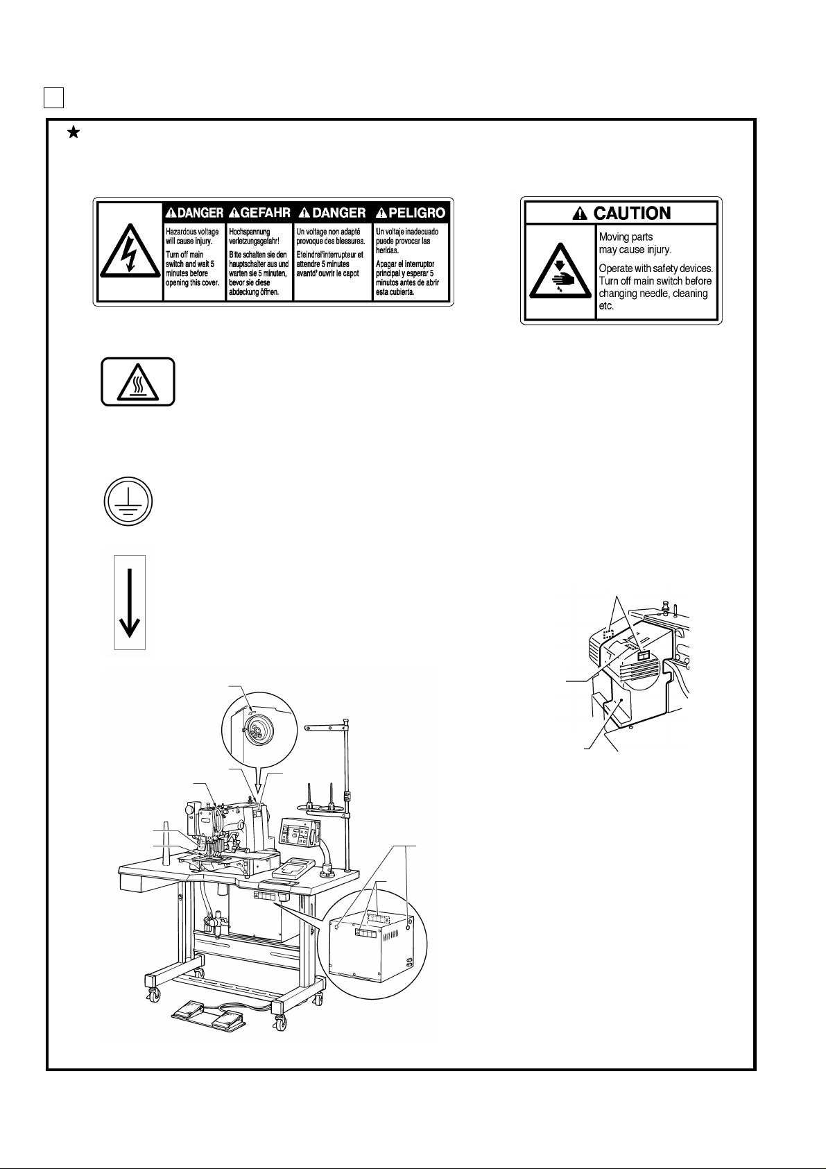
3 Warning labels
4
f
The following warning labels appear on the sewing machine.
Please follow the ins tr uc tions on the labe ls at a ll t imes when using the machine. If the labels hav e bee n r emoved
or are difficult to read, please contact your nearest Brother dealer.
1
3
High temperature warning display
Be sure to connect the ground. If the ground connection is not secure, you run a high risk o
receiving a serious electric shock, and problems with correct operation may also occur .
2
Safety device s
Eye guard
Finger guard
Thread take-up cover
Belt cover
Frame side cover, etc.
5
Direction of operation
Belt cover
Thread take-up cover
Eye guard
Finger guard
1293S
5
Frame side cover
3
1156S
iv
BAS-311F-0, 311F-L, 326F-0
Page 6

CONTENTS
1. NAME OF MAJOR PARTS ..........................................................................................................1
2. SPECIFICATIONS ...................................................................................................................................2
3. INSTALLATION ...........................................................................................................................................3
3-1. Table processing diagram ...............................................................................................................................................4
3-2. Positioning ..........................................................................................................................................................................4
3-3. Installing the control box ..................................................................................................................................................5
3-4. Installing the rubber cushions ........................................................................................................................................6
3-5. Installing the oil pan ..........................................................................................................................................................6
3-6. Installing the cushions ......................................................................................................................................................7
3-7. Installing the switching plate ...........................................................................................................................................7
3-8. Installing the machine head ............................................................................................................................................8
3-9. Tilting the sewing machine head ...................................................................................................................................9
3-10. Connecting the ground wire .......................................................................................................................................11
3-1 1. Connecting the cords (Installing the operation panel) ..........................................................................................11
3-12. Installing the belt cover ................................................................................................................................................14
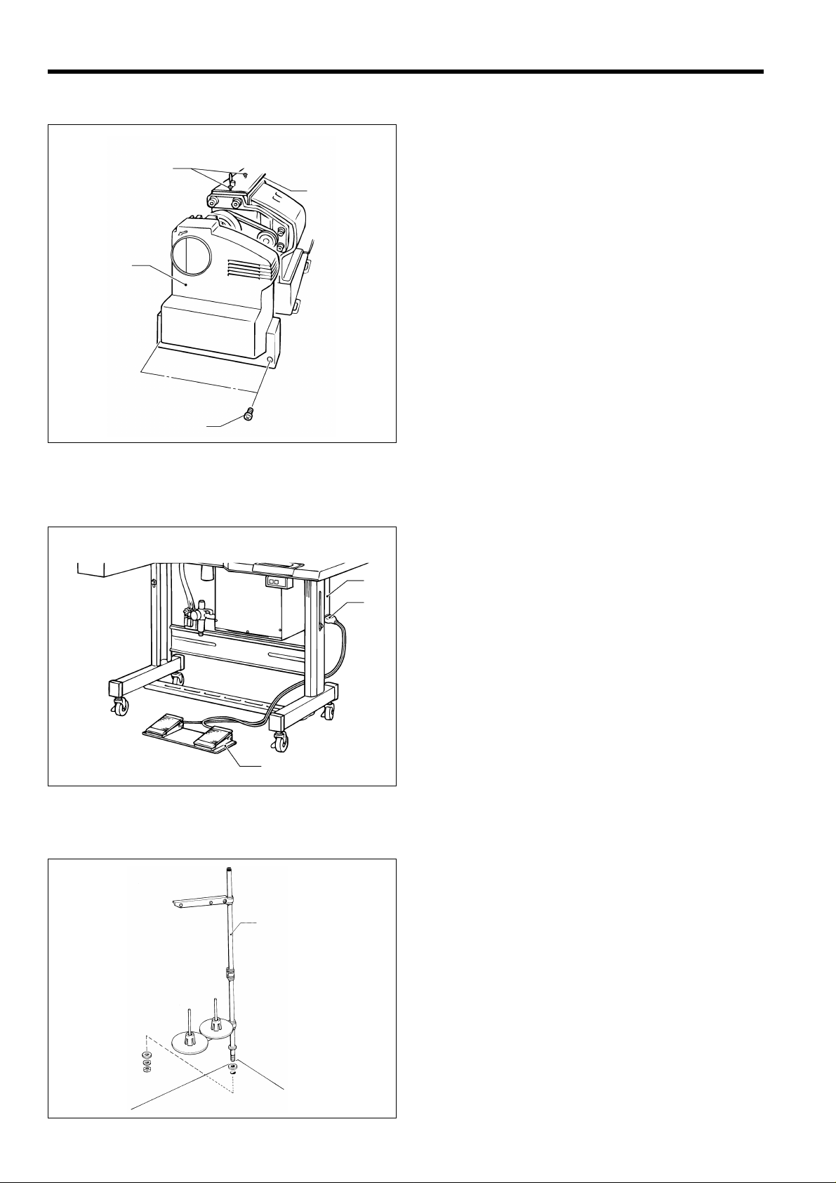
3-13. Installing the foot switch ...........................................................................................................................................14
3-14. Installing the spool stand .............................................................................................................................................14
3-15. Installing the eye guard ...............................................................................................................................................15
3-16. Installing the programmer (option) ............................................................................................................................16
3-17. Installing the w or k clamp li fter conne ctin g rod (BAS-311F-0 solenoid type only) .................................. 16
3-18. Installing the feed base cover supports (BAS-311F -L, 326F-0) .........................................................................17
3-19. Installing the X feed base cover (BAS-311F-L, 326F-0) ...................................................................................17
3-20. Connecting the tubes (pneumatic type only) ..........................................................................................................18
3-20-1. Installing the air unit...................................................................................................................................................19
3-20-2. Adjusting the speed controller ................................................................................................................................19
4. LUBRICATION..............................................................................................................................................20
5. CORRECT OPERA TION.................................................................................................................21
5-1. Selecting the needle and thread ..................................................................................................................................21
5-2. Installing the needle ........................................................................................................................................................21
5-3. Threading the upper thread ..........................................................................................................................................22
5-4. Winding the lower thread ..............................................................................................................................................23
5-5. Replacing the bobbin case and threading the thread .............................................................................................24
5-6. Sewing conditions and thread tension .......................................................................................................................24
5-6-1. Sewing conditions .....................................................................................................................................................24
5-6-2. Lower thread tension ................................................................................................................................................25
5-6-3. Upper thread tension ................................................................................................................................................25
5-6-4. Thread take-up spring height ...................................................................................................................................25
5-6-5. Thread take-up spring tension ..................................................................................................................................25
5-6-6. Adjusting arm thread guide R....................................................................................................................................25
6. USING THE OPERA TION PANEL....................................................................................26
6-1. Explanation of panel .......................................................................................................................................................26
6-2. Using the floppy disk ......................................................................................................................................................28
6-3. Using the program R/W (Read/Write) switch ...........................................................................................................30
6-4. Using the TEST switch (Checking the sewing pattern) ..........................................................................................31
6-5. Using the emergency stop switch ...............................................................................................................................32
6-6. Adjusting the sewing SPEED control .......................................................................................................................33
6-7. Changing the X-SCALE and Y-SCALE settings ......................................................................................................33
BAS-311F-0, 311F-L, 326F-0
Page 7

6-8. Using the bobbin thread counter .................................................................................................................................34
6-9. Using production counter ..............................................................................................................................................35
6-10. Using single split mode ...............................................................................................................................................36
6-11. Shifting a stitch pattern ................................................................................................................................................37
7. SEWING ...............................................................................................................................................................38
7-1. Before starting sewing....................................................................................................................................................38
7-2. Sewing operation ............................................................................................................................................................38
8. CLEANING AND INSPECTION .........................................................................................40
8-1. Cleaning the rotary hook ...............................................................................................................................................40
8-2. Lubrication ........................................................................................................................................................................40
8-3. Draining the oil ................................................................................................................................................................40
8-4. Cleaning the control box air inlet port .........................................................................................................................41
8-5. Cleaning the air holes of belt cover and frame side cover ....................................................................................41
8-6. Cleaning the eye guard .................................................................................................................................................41
8-7. Checking the needle ......................................................................................................................................................41
9. STANDARD ADJUSTMENTS ...............................................................................................42
9-1. Adjusting the needle bar height....................................................................................................................................42
9-2. Adjusting the needle bar lift amount ...........................................................................................................................42
9-3. Adjusting the needle clearance ...................................................................................................................................43
9-4. Adjusting the driver needle guard ...............................................................................................................................43
9-5. Adjusting the shuttle race thread guide .....................................................................................................................43
9-6. Adjusting the movable knife .........................................................................................................................................44
9-7. Adjusting the presser foot..............................................................................................................................................46
9-8. Changing the presser foot lift .......................................................................................................................................47
9-9. Adjusting the wiper .........................................................................................................................................................48
9-10. Adjusting the two-step work clamp lift amount .......................................................................................................49
9-10-1. BAS-311F-0 Solenoid type ....................................................................................................................................49
9-10-2. BAS-311F-0, 311F-L Pneumatic type ....................................................................................................................49
9-10-3. BAS-326F-0 ............................................................................................................................................................50
9-10-4. Adjusting the air pressure ......................................................................................................................................50
9-1 1. Adjusting the nee dle up s top position ......................................................................................................................51
9-12. Checking the input sensor and DIP sw itch input ...................................................................................................52
9-13. Checking the input voltage .........................................................................................................................................53
9-14. Clearing all memory settings .....................................................................................................................................53
10. DIP SWITCH ..............................................................................................................................................54
10-1. Panel DIP switch functions .........................................................................................................................................54
10-2. DIP swtiches inside the control box ..........................................................................................................................56
11. CHANGING SPECIAL FUNCTIONS AND
USING THE MEMORY SWITCHES
........................................................................58
12. ERROR CODES .....................................................................................................................................63
13. GAUGE PARTS LIST ACCORDING TO SUBCLASSES .............66
14. TROUBLESHOOTING .................................................................................................................68
15. OPTIONS ........................................................................................................................................................72
BAS-311F-0, 311F-L, 326F-0
Page 8
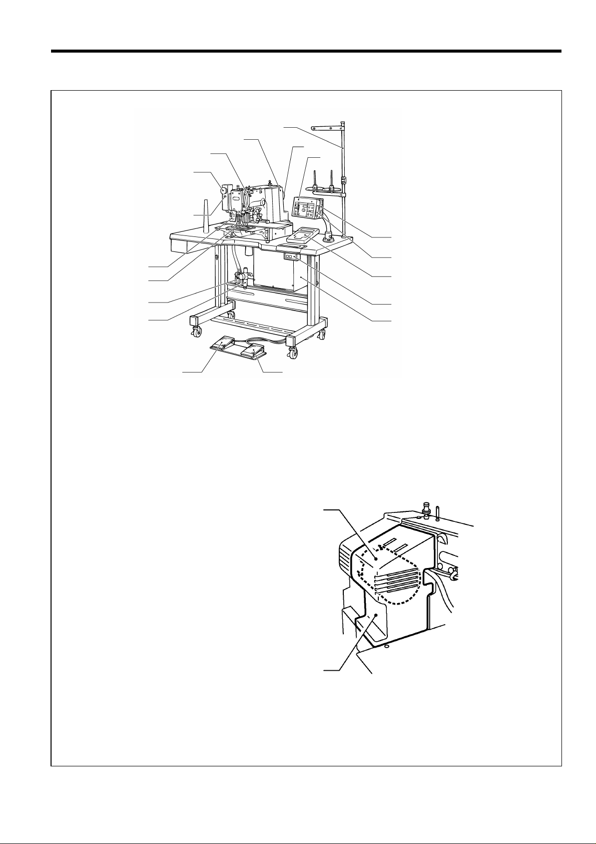
1. NAME OF MAJOR PARTS
(8)
(12)
(1 1)
(16)
(17)
(10)
(9)
(7)
(3)
1. NAME OF MAJOR PARTS
(15)
(18)
(14)
(20)
(19)
1157S
(1) Power switch
(2) Control box
(3) Operation panel
(4) Presser lifter pedal
(5) Starting pedal
(6) Motor cover
(7) Pulley
(8) Spool stand
(14) Programmer
(15) Floppy disk drive
(16) Emergency stop swich
(17) Thread wiper switch
(18) Dip switch
(19) Integrater
(20) Solenoid valve
(4)
(1)
(2)
(5)
(6)
Safety devi ce s
(9) Finger guard
(10) Eye guard
(11) Thread take-up cover
(12) Belt cover
(13) Frame side cover
(13)
1159S
BAS-311F-0, 311F-L, 326F-0
1
Page 9

2. SPECIFICATIONS
A
A
A
2. SPECIFICATIONS
*1
BAS-311F-0 [*1] [*2]
BAS-311F-L [*3]
BAS-326F-0 [*4]
1. For Heavy-weight Materials
2. For Medium-weight Materials
3. For Extra heavy-weight Materials
4. For special use
*3
1. For Heavy-weight materials, Work Clamp Lifter (Pneumatic Type)
4. For special use, Work clamp Lifter (Pneumatic Type)
*4
1. For Heavy-weight Materials, Work Clamp Lifter (Pneumatic Type)
2. For Medium-weight Materials, Work Clamp Lifter (Pneumatic Type)
4. For special use, Work Clamp Lifter (Pneumatic Type)
Stitch formation Single needle lock stitch
Sewing machine Lock stitch, pattern tacking sewing machine (with large shuttle hook)
Maximum pattern size BAS-311F-0: 130 X 60 mm, BAS-311F-L: 220 X 60 mm, BAS-326F-0: 220 X 100 mm
*2
S. Work Clamp Lifter (Solenoid Type)
. Work Clamp Lifter (Pneumatic Type)
Maximum stitch number 20,000 (one pattern)
Stitch length 0.05 - 12.7 mm
Maximum sewing speed 2,500 rpm (When stitch length is 3 mm or less)
Feed mechanism Intermittent feed, pulse motor drive
Rotary hook Shuttle hook (Standard rotary hook is sold separately)
Needle DP X 5, DP X 17, MR
Data storage method 3.5 floppy disk 2HD/1.44MB, 2DD
T e st function Operation test function provided for use with low speed drive
Safety devi ce s
Work clamp height
2-step work clamp
Automatic stop function for activation in the event of misoperation realized with intermediate
stop function and safety circuits
BAS-311F-0:For solenoid - Max. 25 mm, for pneumatic - Max. 30 mm
BAS-311F-L, BAS-326F-0:Max. 30 mm
BAS-311F-0:For solenoid - unit work clamp, for pneumatic - separate work clamp
BAS-311F-L, BAS-326F-0:Separate work clamp
Work clamp lift stroke 18 mm
Intermittent stroke 0 or 3 (Factory default) - 8 mm
Weights
Machine head BAS-311F-0: 65kg, BAS-311F-L, BAS-326F-0: 70kg
Control box: 10 - 20 kg (depending on destination)
Power supply Single-phase 110V, 220V, 240V, 3-phase 220V, 380V, 400V, 600V A
Motor Three-phase 400 W induction motor
Air pressure 0.50 MPa 1.8 l/ min
Power table T-shaped for use sitting or standing
Machine dimensions
1,200W X 590 D X 1,120 H mm (Sitting)
1,350 H mm (Standing) …..Excluding spool stand
BAS-311F-0, 311F-L, 326F-0
2
Page 10
3. INSTALLA TION
3. INSTALLATION
CAUTION
Machine installation should onl y be carried out by
a qualified technician.
Contact your Brother dealer or a qualified
electrician for any electrical work that may need to
be done.
The sewing machine head weighs more than 65 kg
(311F-0), 70 kg (311F-L, 326F-0). The installation
should be car ried out by two or more peopl e.
Do not connect the power cor d until installatio n is
complete, otherwise the machine may operate if
the foot switch is depressed by mistake, which
could result in injury.
Be sure to connect the ground. If the ground
connection is not secure, you run the risk of
receiving a serious electric shock.
Hold the machine head with both ha nds by two or
more peple when tilting it b ack or r eturning it to its
original position. Furth er more, after tilting back the
machine head, do not push the face plate side or
the pulley side from above, as this could cause the
machine head to topple over, which may result in
personal injury or damage to the machine.
All cords should be sec ured at least 25 mm awa y
from any moving parts. Furthermore, do not
excessively bend the ca ble or secure it too firm ly
staples, otherwise there is the danger that fire or
electric shocks could occur.
Install the belt cover and the f rame side cover to
the machine head and motor.
If using a work table which has casters, the casters
should be secured in such a way so that they
cannot move.
Be sure to wear protective goggles and gloves
when handling the lubricating oil and grease, so
that they do not get into your eyes or onto your
skin, otherwise inflammation can result.
Furthermore, do not drink the oi l or eat the gr ease
under any circumstances, as they can cause
vomiting and diarrhoea.
keep the oil out of the reach of children.
BAS-311F-0, 311F-L, 326F-0
3
Page 11
3. INSTALLATION
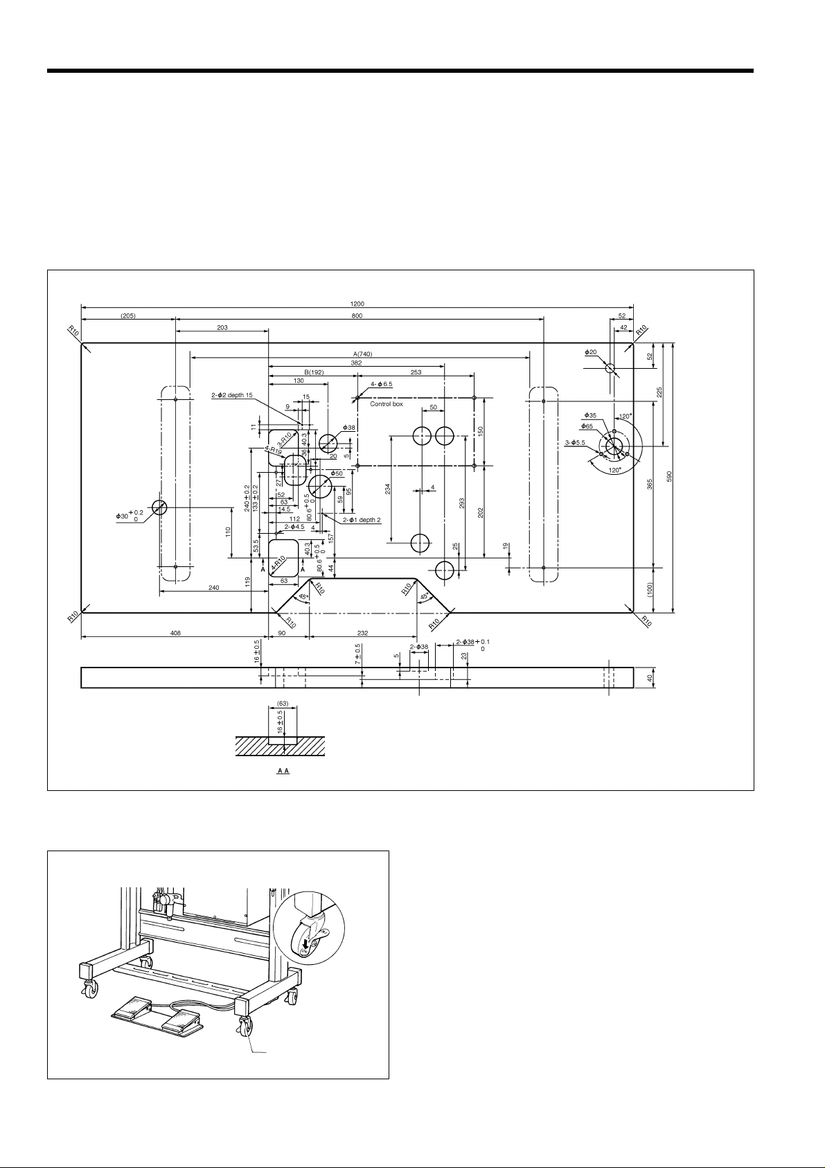
3-1. Table processing diagram
* If using a commercially-available table, process it as shown in the illustration below.
Note
The thickness of the table should b e at least 4 0 mm , and it should be strong enough t o bear the weight
and vibration of the sewing machine.
If the distance A between the insides of the legs is less than 740 m m, move the control box installation
position to the left (B=192 mm).
Check that the control box is at leas t 1 0 m m awa y fr om the leg. If the c ontrol b ox and leg ar e touc h ing, it
could cause the sewing machine to operate incorrectly .
[Standard]
3-2. Positioning
4
1290S
Determine the position for the sewing machine, and then
lock the casters (1) so that the sewing machine will not
move.
(1)
1161S
BAS-311F-0, 311F-L, 326F-0
Page 12
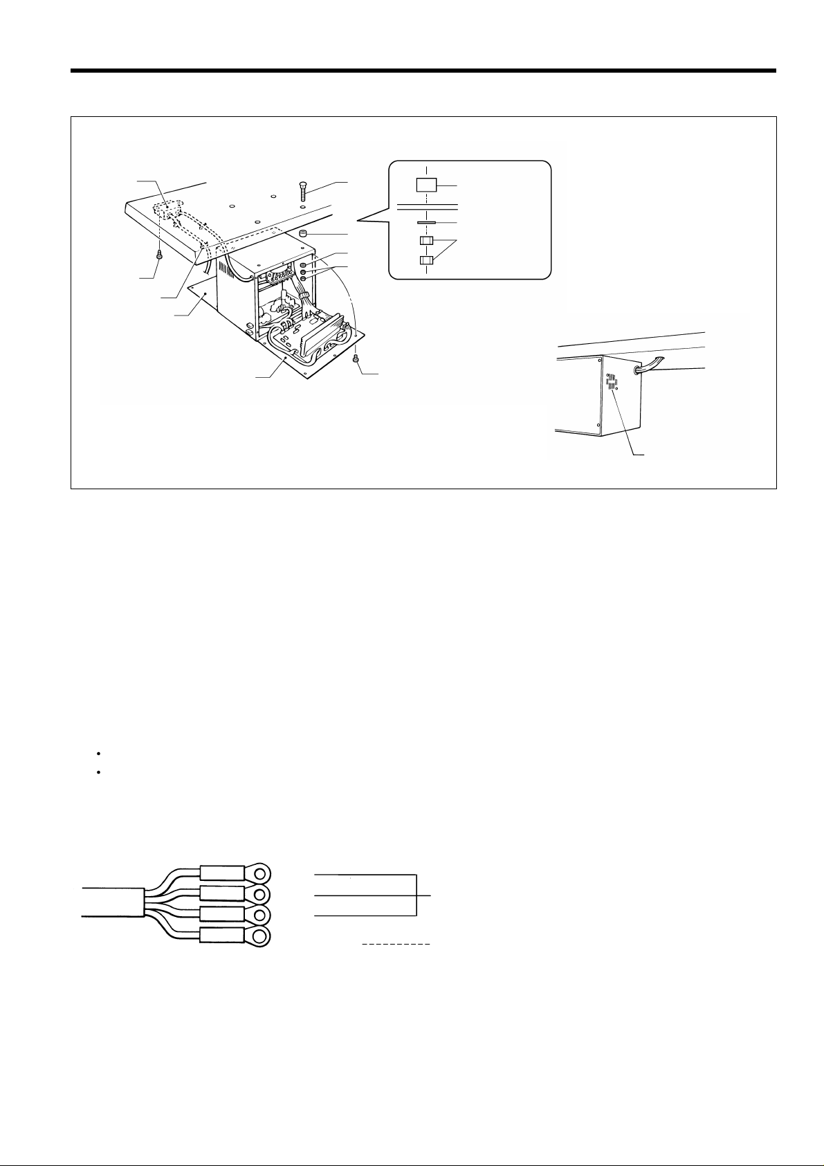
3-3. Installing the control box
/
3. INSTALLATION
(8)
(4)
(5) Sp ace r
(6) Flat washer
(5)
(7) Nut
(6)
(9)
(7)
(10)
(2)
(3)
(1)
(1 1)
1292S1291S
1. Remove the screws (1), and then open the covers (panel mounting assembly (2) and main P.C. board mounting plate
(3)).
Caution: When opening the cover, hold it securely so that it does not fall down.
2. Install the c ontrol box with the four acc essory bolts (4), spacers (5), flat washers (6) and nuts (7) as shown in the
illustration above.
* At this time, leave a gap of approximately 1 mm between the work table and the top of the box.
3. Close the cover s (panel mounting assem bly (2) and main P.C. board mounting plate (3)), and tighten them with the
screws (1).
* The main P.C. board mounting plate (3) will be opened again during "3-11. Connecting the cords", so provisionally
tighten it with the screw (1).
4. Install the power switch (8) with the two screws (9).
5. Secure the power switch cord with the five staples (10).
Note
Secure the motor cord with staples in such a way that it does not cross over the outlet port of the cooling fan (11)
Some specifications are not s upplied with an access ory power switch (10). For these specif ications, connect a
power switch which satisfies the necessary regulations in the country of use.
Red
White
Black
Y ellow
0064Q
BAS-311F-0, 311F-L, 326F-0
Connect to the power switch. However,
the black wire is insulated to the inside of the
box and is not used.
Connect to ground
5
Page 13
3. INSTALLATION
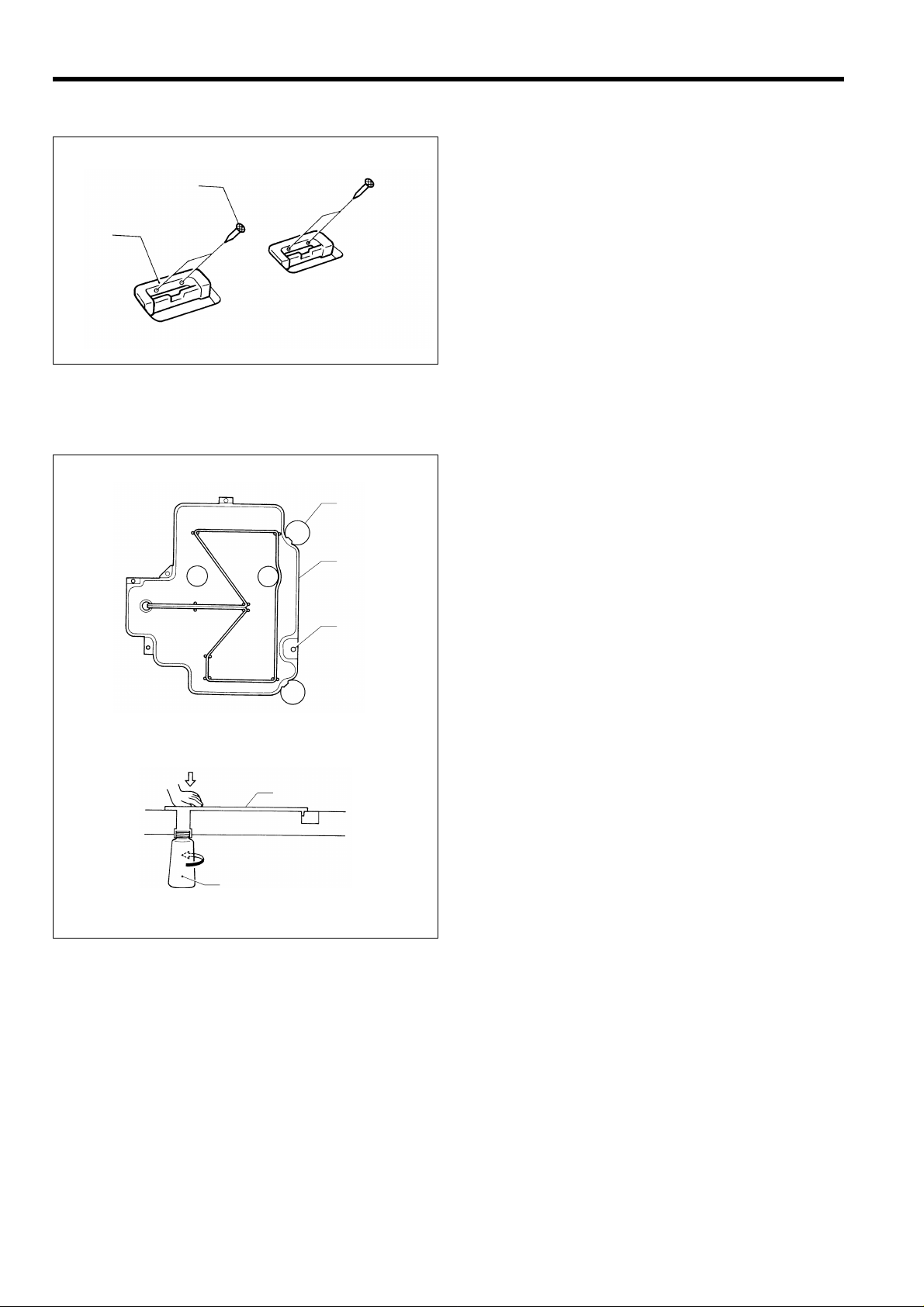
3-4. Installing the rubber cushions
Install the rubber cushions (1) with the nails (2).
* Install so that the head of the nail do es not protrude
(2)
(1)
1296S
from the rubber surface.
3-5. Installing the oil pan
(4)
(2)
(1)
(2)
(3)
0054Q
1. Insert the tabs of the oil pan (2) into the holes f or the
table (1), and then secure it in plac e with t he f iv e na ils
(3) so that the oil pan (2) is not at an angle.
2. While pushing the oil pan (2) down from above, screw
in the oil container (4).
0055Q
6
BAS-311F-0, 311F-L, 326F-0
Page 14
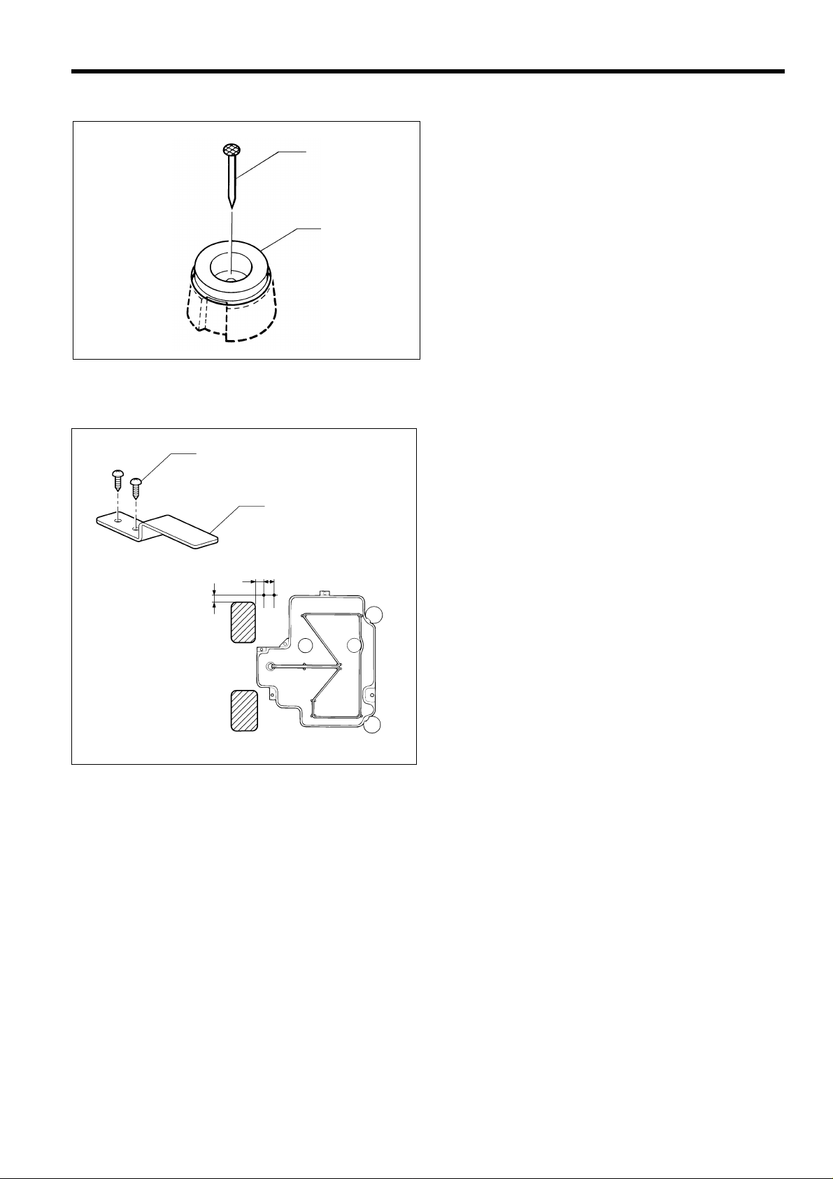
3-6. Installing the cushions
Place the two cushions (1) into the holes in the work table,
(2)
(1)
0056Q
and secure them in place with the nails (2).
* Install so that the head of the nail do es not protrude
3-7. Installing the s witching plate
Install the switching plate (1) to the work table with the two
(2)
(1)
15
9
11
wood screws (2) in the position shown in the illustration.
* The switching plate and the switch brack et which is
3. INSTALLATION
from the rubber surface.
attached to the machine head prevent the sewing
machine from starting when the machine head is tilted
back. Therefore, this means that the sewing m achine
will not start if the switching plate is not installed.
1162S
BAS-311F-0, 311F-L, 326F-0
7
Page 15
3. INSTALLATION
3-8. Installing the machine head
1163S
(2)
(5)
(8)
(9)
(1)
(4)
(3)
(5)
(6)
14.5m
133m
13.2m
Fig. 1
1164S 1165S
1. Insert the head h inges (1) into the machine head so tha t they are parallel, and then secure them with the t wo set
screws (2).
2. Place the machine head gently on top of the rubber cushions (3) and cushions (4).
Note
Poll the cords (5) out as shown in the illustration above in order to prevent them from being clamped by the machine
head.
3. Install the hinge presser (6) with the two bolts.
4. Check that the head position switch is turned on as shown in Figure 1.
5. Connect the motor cord connector (8) to the accessory cord connector (9).
8
BAS-311F-0, 311F-L, 326F-0
Page 16
3. INSTALLATION
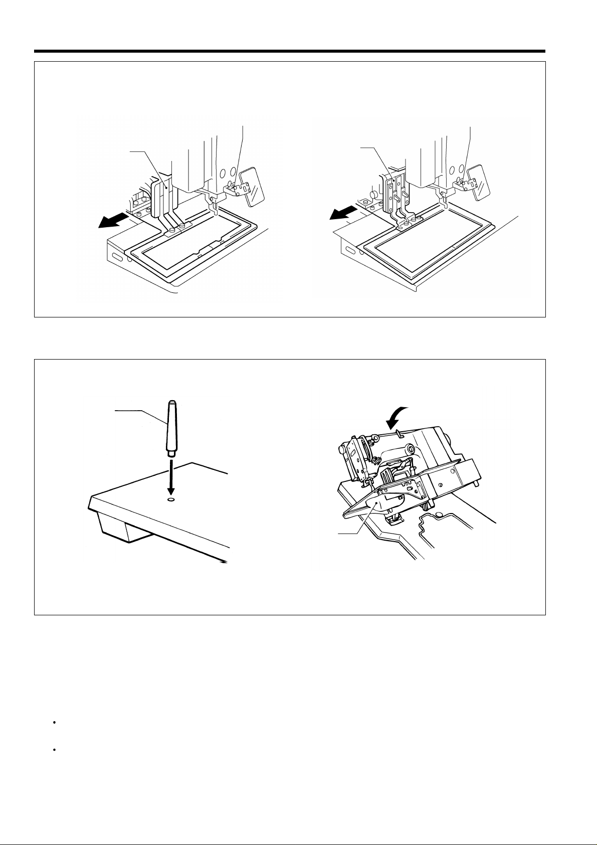
3-9. Tilting the sewing machine head
BAS-311F-L, 326F-0 : Remove the X feed base cover (1) and the feed base cover support (3) (below) from the machine
head before tapping the head rest (5) (next page) into the work table.
BAS-311F-L BAS-326F-0
(2)
(1)
1166S 1167S
(1)
(2)
1. Loosen the sc rews (2) which are ho lding the X feed base cover L assembly (1) by about 2-3 tur ns, and then r em ove
the X feed base cover L assembly (1) in the direction of the arrow in the illustration.
Note
The sewing machine is packed without the X feed base cover L assembly (1) installed.
BAS-311F-L
(3)
1168S 1169S
(4)
(3)
BAS-326F-0
(4)
2. Loosen the sc rews (4) which are holding the feed base cover supp ort (3) on the left of the sewing machine (when
looking from the front of the sewing machine) by about 2-3 turns, lift the feed base cover support (3) up slightly (BAS31 1F-L) or down slightly (BAS-326F-0), and then remove it in the direction of the arrow in the illustration.
Note
The sewing machine is packed without the feed base cover support (3) installed.
BAS-311F-0, 311F-L, 326F-0
9
Page 17
3. INSTALLATION
1170S
(4)
BAS-311F-L
(4)
BAS-326F-0
1171S
3. Move the pres ser arm assembl y (4) as far as it will go in the direc tion of the arro w in the illustration ( to the left when
looking from the front of the sewing machine).
(5)
(5)
(6)
0060Q
1172S
4. Tap the head rest (5) into the table hole.
Note
T ap the head rest (5) securely into the work table as far as it will go.
5. Stand at the left side of the table, and gentl y tilt the m ac hine towards you. When returning the m achine to the or ig ina l
position, be careful of the shuttle hook cover (6) and the cord.
Note
Be sure to have two or m ore people there when tilting back the machine head and returning it to its original
position.
After tilting back the machine head, do not push the face plate or the pulley from above.
10
BAS-311F-0, 311F-L, 326F-0
Page 18
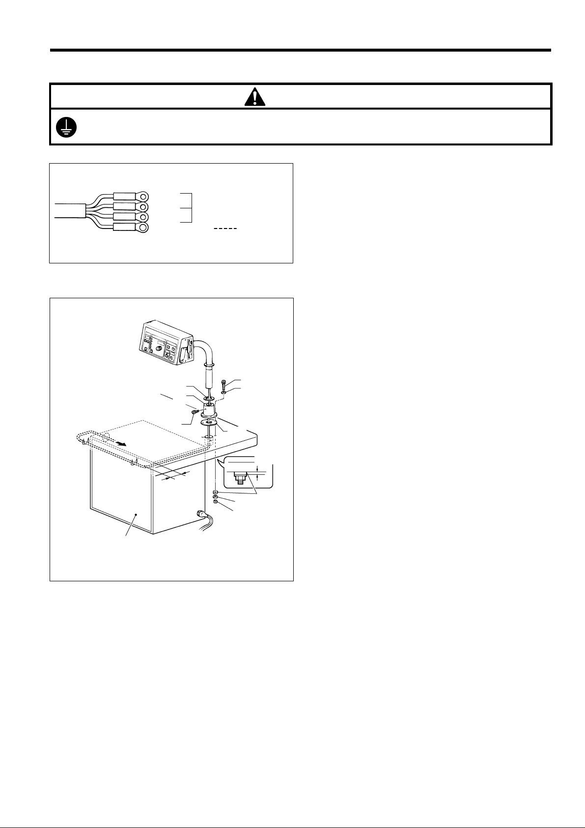
3-10. C onnecting the ground wire
/
(4)
CAUTION
Be sure to connect the ground. If the gr ound connection is not sec ure, you run the risk of receiving a serious
electric shock.
Connection method for 3-phase power supply
3. INSTALLATION
Red
White
Black
Yellow
3-phase
power supply
Yellow/Green
Green
Connect to
ground
0064Q
3-11. C onnecting the cords (Installing the operation panel)
1. Assemble the operation panel stand (1) and cushion A
(2). Then insert the bolts (4) together with the washers
(3) into the three hol es from above, and the n tighten
the nuts (5), washers (6) and cushion B (7) from below
to secure the a ssembly.
Note
Tighten until the thickness of cushion B (7)
becomes about 1 mm.
2. Pass the cords of the control pane l assem bly through
the hole in the operation panel stand (1).
3. Attach the rubber sheet (8) to the hole in the operation
panel stand (1) and then secure it with the bolt (9).
4. Insert the cord into th e c ontrol box throu gh the hole at
the side of the box. Refer to page 13.
5. Secure the cord with the staples ( in two places).
Note
When opening the front cover, check that the code
does not touch it.
Front cover
(8)
(1)
(9)
40 mm
(2)
(6)
(5)
(3)
1 mm
(7)
1587Q
BAS-311F-0, 311F-L, 326F-0
11
Page 19
3. INSTALLATION
(14)
(17)
(10)
(1 1)
(15)
(19)
(18)
(16)
(13)
A
1173S 1073Q
(12)
1175S
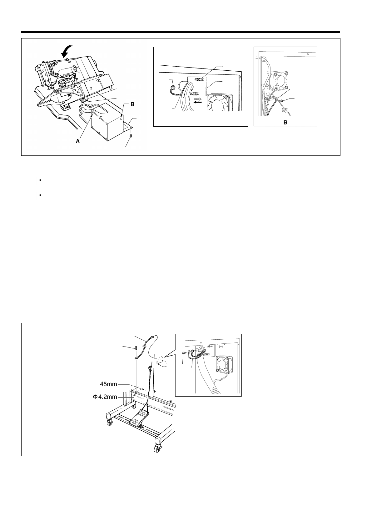
6. Gently tilt back the machine head. Refer to “3-9. Tilting the sewing machine head”.
Note
Be sure to have two or m ore people there when tilting bac k the machine head and retur ning it to its original
position.
After tilting back the machine head, do not push the face side or the pulley side from above.
7. Pass the cords (10) through the hole (11) near the hinge of the work table.
Note
If the cords are passed through the wrong hole, they may become damaged.
8. Gently return the machine head to its original position.
9. Remove the screws (12), and then open the control box cover (main P .C. board mounting plate (13)).
Note
When opening the cover, hold it securely so that it dose not fall down.
10.loosen the two screws (14), and then open the cord presser plate (15) in the direction of the white arrow and pass the
cords (10) through the opening.
1 1.Loosen the screw (17), and then connect the ground wire (16) that is coming from the machine head as shown in the
illustration.
12.Remove the screw (18), and then pass it through the term inal hole i n the ground cor d (19) from upper shaft motor.
Then re-tighten the screw (18) so that the ground cord (19) is secured as shown in the illustration.
Note
Make sure that the ground connections are secure in order to ensure safety.
<BAS-311F-0 Solenoid type only>
(1)
(2)
(3)
(1)
S1. Make hole in the beam as shown in the illustration above. (Button hole diameter is 4.2mm)
S2. Install the ground wire (1) (accessory) to the beam with a tapping screw (2) (accessory).
S3. Loosen the screw (3) , and then conne ct the ground w ire (1) that is coming from the b eam as shown in the ill ustration.
12
BAS-311F-0, 311F-L, 326F-0
1424S
Page 20
Lock the cord
clamp at the top.
3. INSTALLATION
(10)
(21)
(20)
(13)
(12)
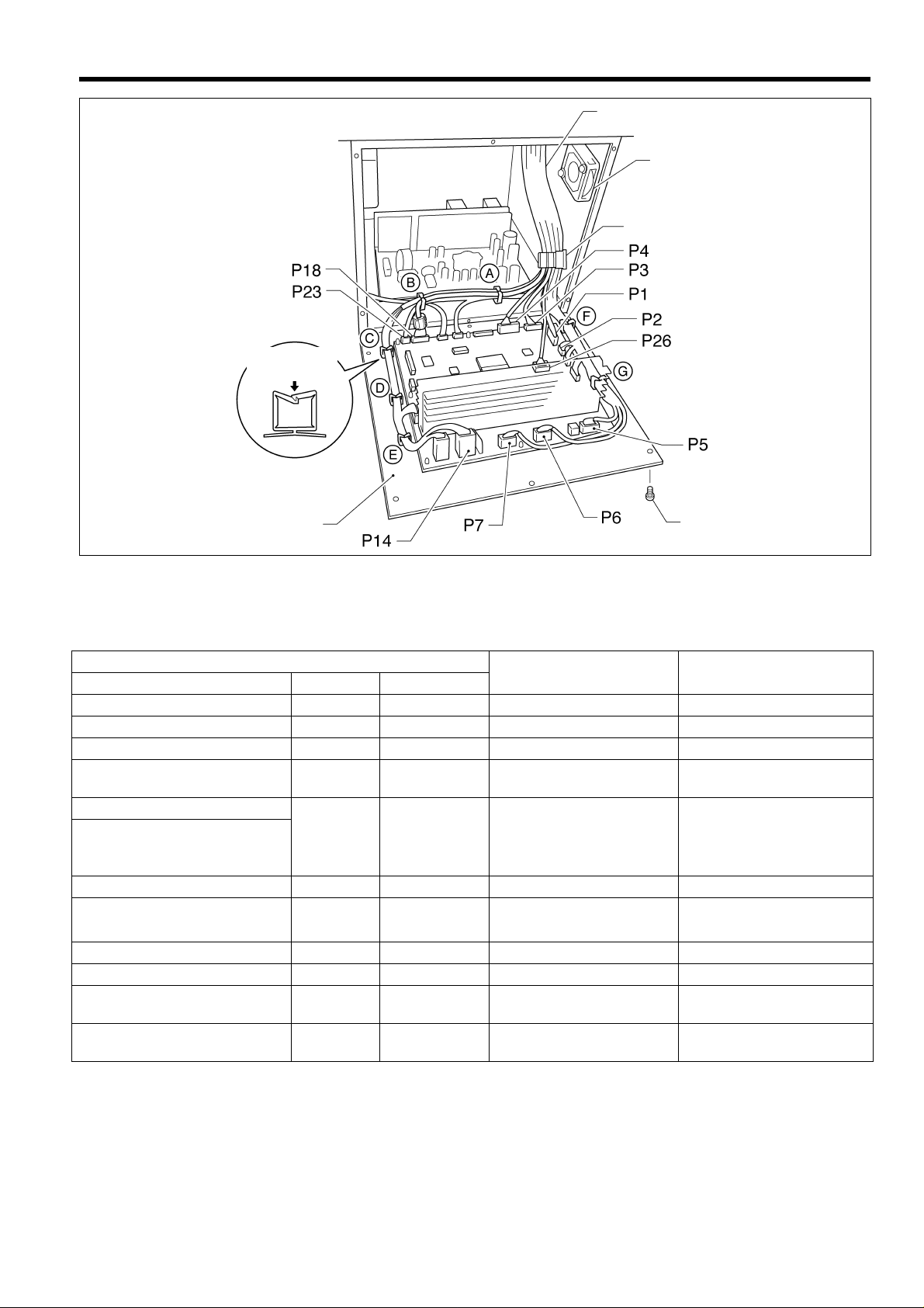
13. Securely connect connectors P1 to P7, P14, P18, P23 and P26 as indicated in table below.
Note
Check that the connector is facing the correct way, and then insert it firmly until it locks into place.
Furthermore, lock the cord clamp at the top.
Machine head connectors
Connection location
No. of pins Cord mark
Connection location on
circuit board
Cord clamps used
X, Y, Sewing sensor 12-pin [1] P1 (ORG) None
Synchronizer 5-pin [2] P2 (SYNCHRO) F
EMERGENCY STOP switch
Solenoid valve
(for pneumatic)
9-pin [3] P3 (HEAD) None
12-pin [4] P4 (VALVE) None
Solenoid
Presser foot
Thread trimmer
8-pin [5] P5 (SOL)
F, G
Wiper
Pulse motor, Y 5-pin [6] P6 (YPM) F,G
Pulse motor, X
5-pin
(blue)
[7] P7 (XPM) F, G
Upper shaft motor 3-pin None P14 (UVM) A, B, C, D, E
Operation panel 10-pin [M] P18 (PANEL) A, B
1176S
Head position switch 3-pin [23] P23 (IMSW) A, B
Machine specification select
connector
10-pin [26] P26 (SELECT) None
14. Secure the cord bundle (10) with the cord clamp (20).
Note
Check that the cords do not get pulled when the machine head is tilted back gently.
15. Close the cord presser plate (15) in the direction of the black arrow, and secure it by tightening the screws (14).
16. Install the control box cover (main P.C. board mounting plate (13)) with the six screws (12).
Note
Check that the cords do not come into contact with the fan (21) and that they are not clamped by the cover at this
time.
BAS-311F-0, 311F-L, 326F-0
13
Page 21
3. INSTALLATION
3-12. Installing the belt co ver
(2)
(1)
(3)
1. Loosen the two screws (2) of the upper cover (1).
2. Insert the belt cover (3) in the direction of the arrow,
and then secure it with the two screws (2) and the two
screws (4).
* it is not necessary to remove the belt cover (3)
when tilting back the machine head.
(4)
1177S
3-13. Installing the f oot s witc h
(1)
(3)
(2)
1178S
Insert the connector of the foot switch (2) into the
connector (3) of the control box (1).
3-14. Installing the spool stand
(1)
0073Q
BAS-311F-0, 311F-L, 326F-0
14
Install the spool stand (1) to the table.
Page 22
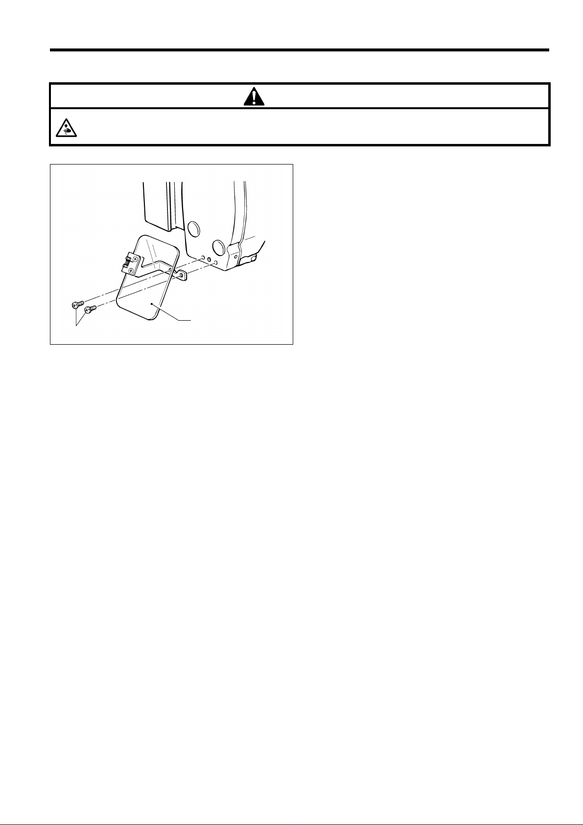
3-15. Installing the ey e guard
CAUTION
Attach all safety devices before using the sewing machine.
If the machine is used without these devices attached, injury may result.
(1)
(2)
1180S
3. INSTALLATION
Install the eye guard ass y (1) to the f ac e pl ate with th e t wo
screws (2).
BAS-311F-0, 311F-L, 326F-0
15
Page 23
3. INSTALLATION
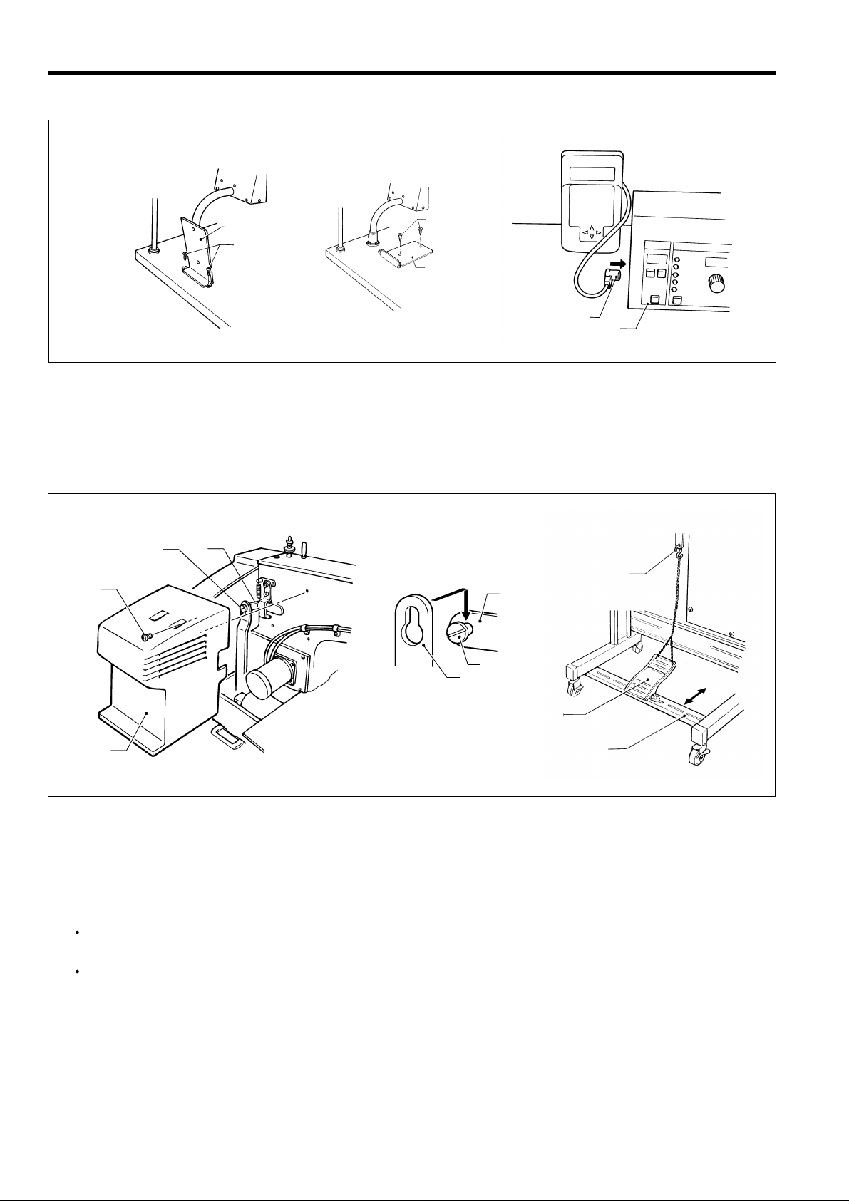
3-16. Installing the programmer (option)
[Vertical]
(2)
(1)
1181S
1. Install the programmer support (2) to the work table with the two screws (1).
2. Insert the programmer connector (4) securely into the left side of the operation panel (3).
[Flat]
(1)
(2)
(4)
(3)
1182S 1183S
3-17. Installing the w ork clamp lifter connecting rod
(BAS-311F-0 solenoid type only)
(3)
(1)
(5)
(7)
(5)
(3)
(4)
(6)
(2)
1184S
1. Remove the four screws (1), and then remove the side cover (2).
2. Install the work clamp lifter connecting rod (4) to the screw (3) on the work clamp lifter lever (5).
3. After installing, re-install the side cover (2) with the four screws (1).
Note
Remove chain hooking back (7) which is attached to the work clamp lifter pedal (6) before tilting back the machine
head.
Move the treadle support base (8) back and for th to adjust so that the c ha in whic h is attached t o the pr es ser lifter
connecting rod (4) and the presser lifter treadle (6) does not touch the cables.
(8)
1185S
16
BAS-311F-0, 311F-L, 326F-0
Page 24
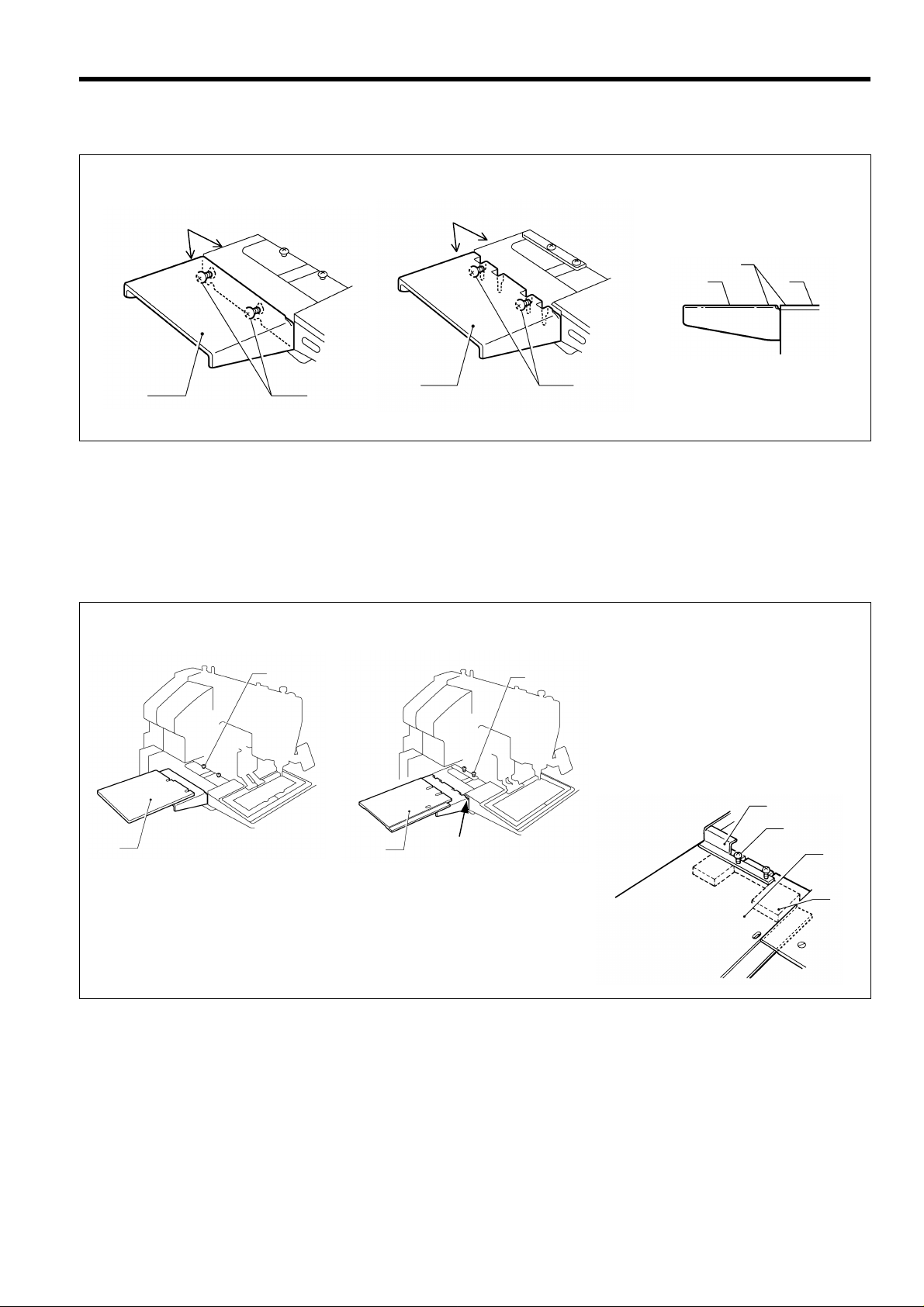
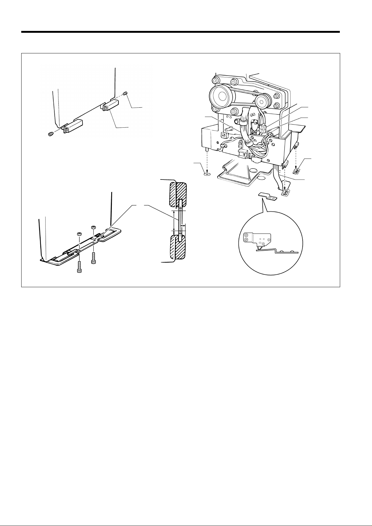
3-18. Installing the f eed base cov er supports
A
(BAS-311F-L, 326F-0)
BAS-311F-L
Coinside
Coinside
BAS-311F-L
Coinside
Coinside
BAS-326F-0
BAS-326F-0
3. INSTALLATION
Coinside
(2)
(3)
(2)
(2)
1168S
1168S
Loosen the four screws (1) on the side of the bed by about 2-3 turns, and then install the feed base cover supports (2) to
the side of the bed so that the top surfaces of the feed base cover supports (2) (one each at left and right) are at the same
height as the top surfaces of the X and Y feed base covers (3) (at left and right).
(1)
(1)
(2)
1169S 1186S
(1)
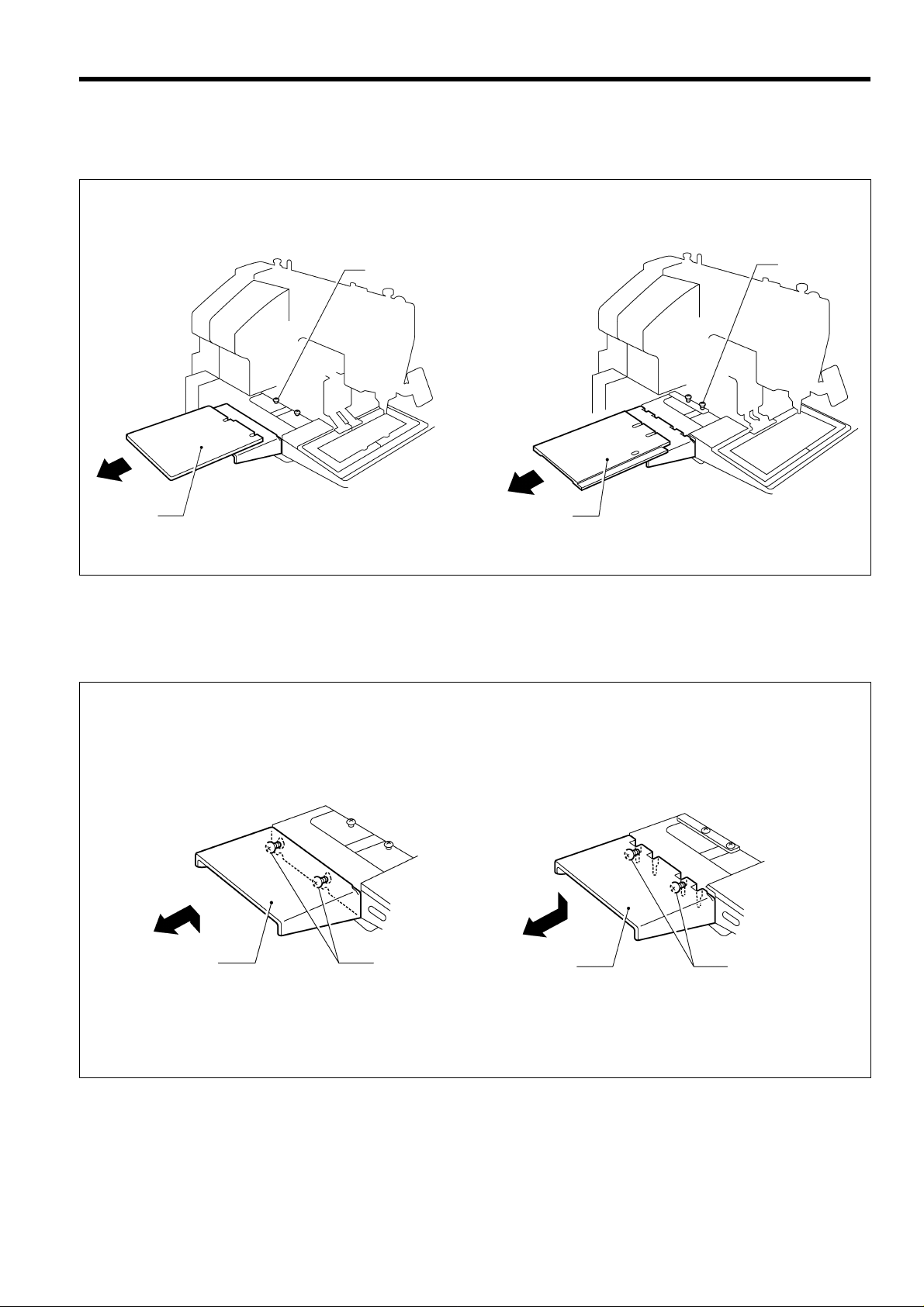
3-19. Installing the X f eed base cov er
(BAS-311F-L, 326F-0)
1167S1 166S
(2)
(3)
(2)
BAS-311F-L
(1)
BAS-326F-0
(2)
(1)
(3)
(4)
1187S
BAS-311F-L
Loosen the four screws (1) by about 2-3 turns, slide the X feed base cover (2) (one each at left and right) in the direction
of the arrow in the illustration, and then tighten the screws (1).
BAS-326F-0
1. Loosen the four screws (2) which are holding the bellows (1) by about 2-3 turns, and then slide the X feed base cover
assemblies (3) (one each at left and right) in the direction of the arrow in the illustration into the gaps (sec tion A)
between the needle plate support plate and the X and Y feed base cover (at left and right).
2. Lift the bellows (1 ) up slightl y, clamp the tops and bottoms of the X feed base cover ass emblies (3) (one each at left
and right) between the bellows (1) and the X feed base (4) and the then tighten the screws (2).
BAS-311F-0, 311F-L, 326F-0
17
Page 25
3. INSTALLATION
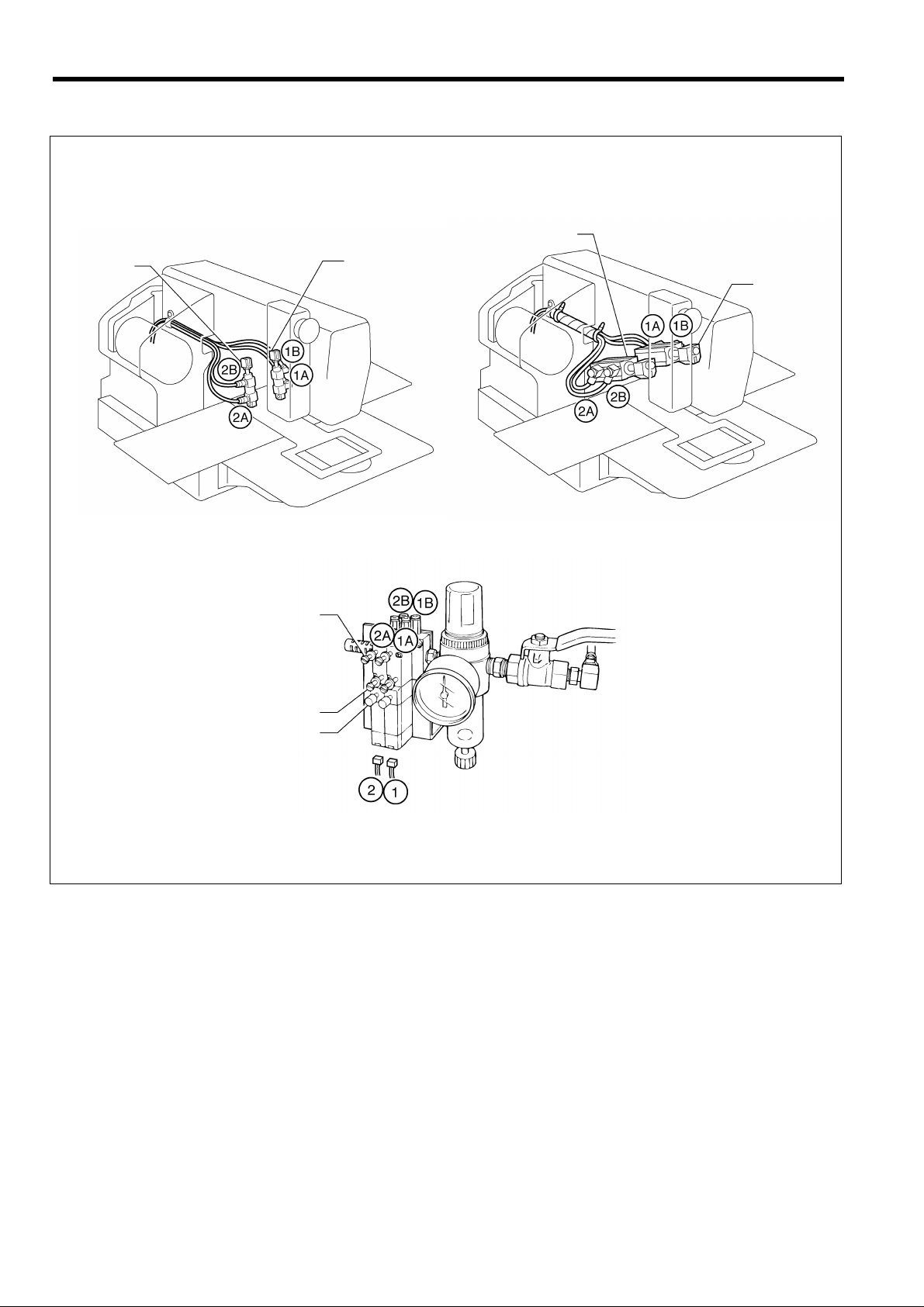
3-20. C onnecting the tubes (pneumat ic type only)
1188S
Cylinder L
BAS-311F-0, 311F-L
BAS-326F-0
1189S
Cylinder L
Cylinder R
Cylinder R
Upper knob
Lower knob
Manual button
0319Q
Connect each air tube to the position with the corresponding number.
18
BAS-311F-0, 311F-L, 326F-0
Page 26

3-20-1. Installing the air unit
Make sure that the air unit does not touch the control box or the work table leg.
(2)
(7)
3. INSTALLATION
(8)
(2)
(4)
(10)
(3)
(1)
(9)
(5)
50 mm
(1)
(6)
120 mm
0320Q 0321Q
<When installing to the underside of the work table>
1. Remove the two screws (1) and the valve setting plate (2).
2. Turn the valve setting plate (2) upside down, and install it to the underside of the work table using the two wood screws
(3) and washers (4) which are provided as accessories.
3. Install the air unit (5) to the valve setting plate (2) with two screws (1).
4. Connect the air hose (6).
5. Adjust the air pressure. (Refer to “9-10-4. Adjusting the air pressure”.)
<When installing to a beam>
1. Make holes in the beam as shown in the illustration above. (Button hole diameter is 5.4 mm.)
Pneumatic work clamp ......Pitch 50 mm Reverse work clamp ......Pitch 120 mm
2. Install the air unit (7) to the beam with two accessory screws (8) and two bolts (9).
3. Connect the air hose (10).
4. Adjust the air pressure. (Refer to “9-10-4. Adjusting the air pressure”.)
3-20-2. Adjusting the s peed controll er
The raising and lowering sp eeds for the work clamp can be adjusted b y screwing the knobs on the valve in an d out.
Adjust the knob position to set the appropriate speed.
If the upper knob is screwed inwar d, the work clamp raising speed becom es slower; if it is screwed outward, the
raising speed becomes faster.
If the lower knob is screwed inward, the work clamp lowering speed become s slower, if it is screwed outward, the
lowering speed becomes faster.
The work clamp can be operated when the power is turned off by pressing the switch.
If the manual button is pushed in and turned to the right, the work clamp can then be held in the raised condition.
Note
The valve knobs should be adjusted so that the left and right sides of the work clamp operate at the same speed.
BAS-311F-0, 311F-L, 326F-0
19
Page 27

4. LUBRICATION
4. LUBRICATION
CAUTION
Turn off the power switch before starting lubricating, otherwis e the machine m ay operate if the foot switch is
depressed by mistake, which could result in injury .
Be sure to wear protective goggles and gloves when handling the lubricating oil and grease, so that they do not
get into your eyes or onto your skin, otherwise inflammation can result.
Furthermore, do not drink the oil or eat the grease under an y circumstances, as they can cause vom iting and
diarrhoea.
Keep the oil out of the reach of children.
Note 1: Fill the machine with oil when the oil level is down to about one-third full in the oil sight glass.
If oil is not added an d the oil drops be low this leve l, there is th e danger that the m achine ma y seize during
operation.
Note 2: Be sure to let the machine operate for a while after adding the oil.
Note 3: If there is no more oil on the felt of the shuttle race base, problems with sewing may result, so add oil to the felt
until it is slightly soaked.
Note 4: Use only specified Brother oil (Nisseki Mitsubishi Sewing Lube 10N; VG10) for the machine oil.
Lubrication points
BAS-311F-0, 311F-L
1. Fill the arm-side oil tank with oil.
1190S
BAS-326F-0
(2)
(1)
1191S
2. Fill the bed-side oil tank with oil.
BAS-326F-0
When filling the bed oil tank with oil, move the presser arm (1) to the X direction sewing home position so that
the oil hole in the X feed base cover L assembly (2) is aligned with the oil hole in the bed, and then fill the bed
oil tank with oil.
BAS-311F-0, 311F-L, 326F-0
20
X direction sewing
home position
1192S
Page 28

4. LUBRICATION/ 5. CORRECT OPERATION
t
(1)
1193S
3. Add oil to the felt (1) of the shuttle race base.
* When setting up the sewing machine and when i
hasn't been used for an exten ded period of time, be
sure to add 2-3 drops oil to the felt.
4. If using the liquid cooling tank (1), fill it with silicon oil (100
2
mm
/s).
5. CORRECT OPERATION
5-1. Selecting the needle and thread
Needle Thread Main application
DP X 5 # 9 #100 - #60 Knitted wear
DP X 5 # 16 #80 - #50 General clothing
DP X 17 # 19 #50 - #20 Denim
DP X 17 # 21 #50 - #20
DP X 17 # 25 #20 - #4 Leather, seat belts
Leather, denim
5-2. Installing the needle
Different needles and threads are us ed f or diff erent s ewing
applications.
Refer to the table at left for details on which needle and
thread to select.
(1)
0080Q
(2)
Loosen the set screw (1) , insert the needle (2) as far as it
will go so that the groove is facing toward you and then
tighten the set screw (1).
(1)
1194S
BAS-311F-0, 311F-L, 326F-0
21
Page 29

5. INSTALLATION
5-3. Threading the upper thread
CAUTION
If the power switch needs to be left on when carrying out thr eading, be extrem ely cafeful to observe all safet y
precautions.
The machine may operate if the foot switch is depressed by mistake, which could result in injury.
(ex. Continuing sewing from a stopping point)
[When using cotton thread] [When using the liquid cooling tank]
(1)
40 mm
1196S
Thread the upper thread correctly as shown in the illustration above.
Note
Turn the machine pulley and raise the thread take-up lever (1) before threading the upper thread.
(This will make threading easier and it will prevent the thread from coming out at the sewing start.)
When threading the thread through the needle, allow a distance of approximately 40 mm between the needle hole
and the end of the thread. If the trailing length of the thread is too long, it may cause the thread to.
1197S
22
BAS-311F-0, 311F-L, 326F-0
Page 30

5-4. Winding the lower thread
CAUTION
Do not touch or place anything against any of the moving parts while winding the lower thread, otherwise
personal injury or damage to the machine may result.
(1)
1198S
5. CORRECT OPERATION
1. Place the bobbin all the way onto the shaft.
2. Thread the thread as s hown in the illustration at left,
wind the thread around the bobbin several times in the
direction of the arrow, and then press the bobbin
presser (1).
3. Turn on the power switch.
(The POWER indicator on the operation panel will
illuminate.)
For solenoid specifications, lower the work clamp
(depress the work clamp lifter pedal (6)).
1199S
0106Q
(2)
(1)
(4)
(2)
(6)
(3)
(1)
1429S
4. Check that the needle is not touching the presser foot,
and then while pressing th e STEP BACK switch (2),
depress the foot switch (3) to start the m achine. Kee p
depressing the foot switch (3) until the lower thread
stops being wound onto the bobbin.
Release the STEP BACK switch (2) after the machine
starts operating.
If you release the foot s witch before winding is com pleted, depress it once m ore while press ing and holding the STEP BACK switch (2).
5. The bobbin press er (1) will automaticall y return to its
(5)
original position after a set amount of thread (80 - 90%
of the bobbin capacity) has been wound on.
6. Release the foot switch (3).
7. Remove the bobbin, hook the thread onto the knife (4),
and then pull the bobbin in the direction of the arrow to
cut the thread.
8. To wind more thread onto the bob bin, loosen the set
0107Q
screw (5) and pull the bobbin presser (1) outward.
<< If the thread winds onto the bobbin unevenly >>
If the thread winds onto th e bobbin unevenly, loosen
the nut (1) and turn the bobb in winder thread tensio n
stud (2) to adjust.
A
Note
If the thread winds on as s hown in A, turn the bobbin
winder thread tension stud (2) clockwise; if it winds on
as shown in B, turn the bobbin winder thread tension
stud (2) counterclockwise.
B
0108Q
BAS-311F-0, 311F-L, 326F-0
23
Page 31

5. INSTALLATION
5-5. Replacing the bobbin case and threading the thread
CAUTION
If the power switch needs to be l eft on when carrying out replacing the bob bin, be ex tremely careful to observe
all safety precautions.
The machine may operate if the foot switch is depressed by mistake, which could result in injury.
(ex. Continuing sewing from a stopping point)
(2)
(1)
(3)
(4)
30 mm
1201S
1. Pull the shuttle race cover (1) forward and then open the cover.
2. Lift the bobbin case latch and remove the bobbin case.
3. Insert a new bobbin into the bobbin case, and then pass the thread through the slot (2) and pull it out from the thread
hole (3). Check that the bobbin turns in the direction of the arrow when the thread is pulled at this time.
4. Pass the thread through the lever thread hole (4), and then pull out approximately 30 mm of thread.
0110Q 1202S
5-6. Sewing conditions and thread tension
5-6-1. Sewing conditions
BAS-311F-0, 326F-0 BAS-311F-0 BAS-311F-L
Specifications For heavy materials
Upper thread # 20 or equivalent # 50 or equivalent # 4 or equivalent
Lower thread # 20 or equivalent # 60 or equivalent # 4 or equivalent
Upper thread
T ension (N)
Lower thread
T ension (N)
Thread take-up
spring height (mm)
Thread take-up
spring tension (N)
1.4 - 1.8 1.0 - 1.3 4.5 - 5.0 1.4 - 1.8
0.2 - 0.3 1.0 - 1.2 0.3 - 0.4
6 - 8 0 6 - 8 mm
0.4 - 0.6 0.15 - 0.35 - 0.4 - 0.6
For medium
materials
For extra heavy
materials
For heavy materials
(denim)
# 20 or equivalent
(cotton)
# 20 or equivalent
(cotton)
Pre-tension (N) 0.3 - 0.5 0.1 - 0.3 0.3 - 0.5 0.2 - 0.4
Needle DP X 17 # 21 DP X 5 # 16 DP 17 # 25 DP X 17 # 19
Normal sewing
speed
The sewing conditions given in the above table may need to be changed depending on the article being sewn.
24
2000 rpm 2000 rpm 1300 rpm 2000 rpm
BAS-311F-0, 311F-L, 326F-0
Page 32

5. CORRECT OPERATION
t
(5)
5-6-2. Lower thread tension 5-6-3. Upper thread tension
Stronger
Weaker
(3)
(2)
Stronger
(1)
Weaker
Stronger
Weak e r
Weak e r
0112S
Set the lower thread tension to as weak a tension as
possible and so that the bobbin case drops by its own
weight when the end of the thread is held. Turn the
adjusting screw (1) to adjust the tension.
Note
Turn the tension nut (2) (main tension) to adjust the tension
as appropriate for the material being sewn.
Furthermore, turn the thread n ut (3) (s ub-tension) to adjus
the remaining length of upper thread to approxim ately 40
mm.
If the lower thread tens ion is too weak, it m ay not be
possible to cut the lower thread properly during thread
trimming .
5-6-4. Thr ea d t ake- up s pr i n g h e i gh t 5-6-5.
Lower
Higher
A mm
(4)
1203S
Thread take-up spring tension
(5)
Stronger
1204S
Loosen screw (4) and turn the entire thread take-up unit to
adjust so that the height of the thread take –up spring is A
mm. (Refer to “5-6-1. Sewing conditions”)
5-6-6. Adjusting arm thread guide R
Become greater
Become less
(2)
(1)
1206S
BAS-311F-0, 311F-L, 326F-0
Weak e r
1205S
Adjust the thread take-up spring tension by turning the
tension stud
with a screwdriver.
The standard position of arm thread guide R (1) is the
position where the screw (2) is in the center of the
adjustable range for arm thread guide R (1).
To adjust the position, loosen the screw (2) and then
move arm thread guide R (1).
When sewing thick material, move arm thr ead guide R ( 1)
to the left. (The thread take-up amount w ill become greater .)
When sewing thin material, move arm thread guide R (1) to
the right. (The thread take-up amount will become less.)
25
Page 33

6. USING THE OPERATION PANEL
(7)
(8)
(9)
(10)
(11)
6. USING THE OPERATION PAN EL
6-1. Explanation of panel
(5)
(2)
(3)
(4)
(6)
(1) POWER indicator .......................When the power is turned on, the indicator lights to show that the power is on.
(2) PROGRAM No. display..............Displays the program number 00 - 99.
(3) Program select switch................ Used to select the program number when reading a program from or writing a
program to disk.
(4) Program Read/Write switch ...... Used to read a program from floppy disk, or to write a newly programmed stitch
pattern to floppy disk.
Up to ten patterns (00 - 99) can be stored on each disk.
(5) Display screen ............................Used to display data such as menus, errors and memory switch settings.
(6) Menu switch ................................ Used to selec t the desired menu (scale, speed, bobbin thread counter, split No.).
One of the indicators (7) - (11) illuminates to in dicate the menu selected, and the
setting for that menu them appears on the display screen (5).
The illuminated indicator changes in the following order each time the switch is
pressed.
(1)
1207S
X-SCALE indicator (7) Y-SCALE indicator (8) SPEED indicator (9)
B.T. COUNTER indicator (10) SPLIT NO. indicator (1 1)
(7) X-SCALE indicator ....................Illuminates when X-scale mode has been selected using the menu switch (6).
(8) Y -SCALE indicator...................... Illuminates when Y -scale mode has been selected using the menu switch (6).
(9) SPEED indicator......................... Illuminates when speed mode has been selected using the menu switch (6).
BAS-311F-0, 311F-L, 326F-0
26
Page 34

(5)
(10)
(11)
(5)
6. USING THE OPERATION PANEL
(13)
(14)
(12)
(16)(6)
(15)
(17)
1208S
(10) Bobbin Thread COUNTER........... Illuminates when bobbin thread counter mode has been selected using the menu
indicator switch (6).
(11) SPLIT NO. indicator........................Illuminates when split No. mode has been selected using the menu switch (6).
(12) Dial ..................................................The setting shown on the displa y screen ( 5) can be cha nged by turni ng this dia l
while pressing the STEP BACK switch (17).
(13) Bobbin Thread SET switch.................Used to s tore the num ber of work pieces dis pla yed in the bobbin thr ead count er
to floppy disk.
(14) Bobbin Thread CHANGE ..............Used to continue sewing after replacing the bobbin thread.
switch (An alarm will sound when the counter reads <000>. Sewing is not possible when
the counter reads <000>.) (Refer to "6-8. Using the bobbin thread counter".)
(15) TEST switch....................................Used to move the feed mechanism only in order to conf ir m a programmed st itch
pattern.
(16) TEST indicator ................................Lights when the TEST switch is pressed.
(17) STEP BACK switch ........................Used when winding a fresh bobbin, or when correcting a stitch pattern due to a
(RESET switch) broken needle thread.
Also used to reset error displays.
BAS-311F-0, 311F-L, 326F-0
27
Page 35

6. USING THE OPERATION PANEL
6-2. Using the floppy disk
<Compatible types of floppy disk>
Data type
300E type
(300F type)
T a jima embroidery data 50, 0 00 s t i tch e s p er p a t ter n 0.1 mm/pulse
Old 300A type
Old 300 data
The above four types of data can all be read, but when writing to disk , all data is automaticall y converted to 300F,
300E data when writing to 2HD disks and 300A dat a w hen writing to 2DD disks.
When using a 2HD disk, use a disk which has been pre-formatted as a 1.44 MB disk. (The programmer can be used
to format these disks. Refer to the programmer instruction manual for details.)
TFD embroidery data can be em broidered after it has been converted by the program mer to BAS-300F and BAS-
300E data.
Restriction on using 2DD floppy disks.
In order to maintain compatibility with the old 300A series, the following restrictions have been placed on the use of
the new functions which have been added to the E series.
No. of stitches
programmed
20,000 stitches per
pattern 100 pattern
Up to a maxi-mum
of 360,000 stitches
4,000 stitches per
pattern 10 patterns
Up to a maximum of
40,000 stitches
2,000 stitches per
pattern 10 patterns
Up to a maximum of
20,000 stitches
Data resolution Disk Format
0.05 mm/pulse Yes
2HD 1.44 MB
0.1 mm/pulse Yes
2DD
0.2 mm/pulse
Automatically
formatted
Write
enabled
No
No
Restricted function A series (2DD) F, E series (2HD)
Resolution 0.1 mm/pulse 0.05 mm/pulse
Low-speed conversion
Split function
during embroidering
Needl e do wn s top f or spli t Not available Available
Expansion option output Not available Available
2 types
(400 and 1,200 revolutions)
Not available Available
4 types (400, 600, 800and
1,200 revolutions)
Applicable
command
[668] L
[669] L
[220] L
[230] L
[221] L
[231] L
28
BAS-311F-0, 311F-L, 326F-0
Page 36

Setting the floppy disk
(2)
(5)
(4)
6. USING THE OPERATION PANEL
Unlocked writing possible
Window open(3)
(1)
(6)
locked writing possible
1209S
1210S
1211S
1. Turn on the power switch (1). The POWER indicator (2) will illuminate and the machine model number will appear o n
the display screen.
2. Hold the d isk (3) with the labe l up and th e shutter to the f ront, and insert the d isk into the dri ve (4). It will click into
place.
3. To eject the disk, press the eject button (5).
Note
Slide the write protector (6) on the back of the disk up (the window opens) to lock the disk and prevent accidental
erasure of the disk contents.
Inserting the disk into the dri ve upside down or backwards may dam age the drive and will prevent reading or
writing of data.
Be sure to store your disks away from any magnets or magnetic sources, including radios, televisions, tele-
phones, and other devices. Magnetism can erase or damage disk contents. Also, be careful to prevent
exposure of the disk to oil or dust.
Be sure to make a copy of the floppy disk containing sewing data and keep the master floppy disk.
When the R / W operation is not in operation, eject the floppy disk from the floppy disk drive and keep it in a case
for floppy disk only to prevent exposure of the disk to dust.
When the “E.4F” error (Reading error of sewing data) occurs very often;
1. Clean the floppy disk drive using the cleaning disk.
2. Read the sewing data. If the “E.4F” error occurs again, the floppy disk may be dam aged. In this case, clean the
floppy disk drive with the cleaning disk again.
3. Read the sewing data from the master floppy disk and write it in a new floppy disk. Do not use any damaged floppy
disks again.
How to use the cleaning disk
1. Insert the cleaning disk into the floppy disk drive.
2. Select a program number (0-9), and press the “R/W” switch. If you select the same program number for cleaning every
time, the same location of the clea ning dis k is used and the lifetim e of the cleaning dis k will becom e shor t. Next tim e
you clean it, select a different number.
3. After the cleaning is com pleted, the “E.4F” error appear s. The error appears because the cle aning disk has no data.
This is normal.
4. Cancel the error and eject the cleaning disk.
BAS-311F-0, 311F-L, 326F-0
29
Page 37

6. USING THE OPERATION PANEL
6-3. Using the program R/W (Read/Write) switc h
Programmed stitch patterns stored on f loppy disk can be read into memory, and newly programmed patterns can be
written to disk for permanent storage and later recall.
1212S
(7)
(1)
(5)
Insert the floppy dis k (1) c ontaining or whic h is to co ntain
the programmed stitch pattern.
T o READ a pa ttern to memory
Press the program select switch (3) on the operation
panel. The program number will then appear in the
PROGRAM NO. display (2). After selecting the desired
program number, press the R/W switch (4). The disk drive
indicator (5) will illuminate and a "P" will appear on the
PROGRAM NO. display (2) to indicate that the data is
being read. When the alarm sounds and the disk drive
indicator (5) turns off, the program number will then flas h
in the PROGRAM NO. display ( 2) instead of the "P" to
indicate that the reading of the data is complete.
(2)
(3)
(4)
(6)
(7)
(8)
1213S
1215S1214S
1216S
T o WRITE a pattern to disk
Press the program select switch (3) on the operation
panel to select the desired program number. After
programming the pattern using the stitch programmer,
press the R/W switch (4) The disk drive ind icator (5) will
illuminate and a "P. " will appear on the PROGRAM NO.
display (2) to indicate that the data is being written. When
the alarm sounds and the disk drive indicator (5) turns off,
the program number will then flash in the PROGRAM NO.
display (2) instead of the "P " to ind ic ate t hat th e writ ing of
the data is complete.
If an error message is displayed
If an error message code is displayed in the displa y (7),
and alarm will sound.
Press the emergenc y stop switch (6) on the front of the
machine to stop sewing machine operation, and then
refer to and follow the error code list on page 63.
Clearing the error
1. Turn the EMERGENCY STOP switch (6) clockwise
and then pull it forward to release it.
2. Press the STEP BACK (RESET) switch (8) on the
operation panel
(when memory switch No. 0d is ON).
If memory switch No. 0d is OFF, press the
EMERGENCY STOP switch (7) once more to release
it.
30
BAS-311F-0, 311F-L, 326F-0
Page 38

6. USING THE OPERATION PANEL
(15)
6-4. Using the TEST switch (Chec king the sewing pa ttern)
Use the TEST switch to begin sewing again from any desired point when the thread breaks or the bobbin thread runs out.
1217S
(16)
(2)
1215S
(17)
(1)
1. Press the TEST switch (15). The indicator (16) will
light.
2. If the work clam p is raised, depress the work clamp
lifter pedal (2) to lower the work clamp.
3. Press the starting pedal (1).
Note
After the feed mechanism has returned to the
home position, it will then m ove the sewing start
position and the program number will stop
flashing.
This only occurs the first time that a program is
selected.
4. Press the starting pedal (1). (The needle will rem ain
stationary as the work clamp advances through the
pattern at low speed one stitc h at a time. Pres s the
presser lifter pedal (2) to fast forward.
If the STEP BACK switch (17) is pressed while moving
at low speed when memor y switch No. 20 is ON, the
work clamp will move in the forward direction in steps
of 100 stitches.
5. When the work clamp reaches the desired position,
press the TEST switch (15). The work c lam p will stop,
and the test indicator (16) will go out. If the work clamp
was stopped too early, press theTEST switch (15)
again to proceed.
If the work clamp was stopped too late, press the
STEP BACK switch (17) to advance t he work clamp
one stitch at a time.
1218S
Resuming operation from a stopping poing
6. Sewing will start when the starting pedal (1) is
pressed.
BAS-311F-0, 311F-L, 326F-0
31
Page 39

6. USING THE OPERATION PANEL
6-5. Using the emergency stop switch
Press the emergenc y stop switch to imm ediately stop the sewing machine during actual sewing or when in the test
mode.
1216S
(1)
Clearing the error
1. Turn the EMERGENCY STOP switch (1) clockwise
and then pull it forward to release it .
2. Press the STEP BACK (RESET) switch (17) on the
operation panel. (The buzzer will stop sounding.)
3. If you do not wish to resume sewing, press the
EMERGENCY STOP switch (1) once more to release
it, and then press the ST EP BACK (RESET) switch
(17) so that the operation panel d ispla y flashes . The
sewing machine will then be ready for the next sewing
operation.
* If memory sewing No. 0d is OFF, press the EMER-
GENCY STOP switch (7) once more to release it.
1215S
1219S
1200S
(15)
(18)
(17)
(17)
1215S
Continuing sewing from a stopping point
If you press the EMERGENCY STOP switch after the
thread breaks or the bobbin thread runs out during sewing,
you can then resume swing from the point where the
thread broke or ran out.
1. Press the EMERGENCY STOP switch to release it.
2. Press the STEP BACK (RESET) switch (17) to trim
the thread.
3. Press the STEP BACK (RESET) switch (17) once
more.
(The sewing machine will move stitch by stitch in the
reverse direction while this switch is pressed.)
If the sewing machine m oves back too far, press the
TEST switch (15) to move it forward again. Press the
TEST switch (15) again to stop the machine.
4. After you have reached the desir ed position, depress
the starting pedal to start sewing.
32
BAS-311F-0, 311F-L, 326F-0
Page 40

6. USING THE OPERATION PANEL
(17)
6-6. Adjusting the sewing SPEED control
The sewing speed can be changed in steps of 100 rpm to the appropriate speeds for each stitch length setting.
1. Press the MENU sw itch (6) until the SPEED indicator
(9) illuminates.
2. While pressing the ST EP BACK switch (17), turn the
dial (12) until the desired speed is displayed.
The display will change in steps of 10 rpm.
(9)
(17)
(6)
(12)
1220S
1215S
6-7. Changing the X-SCALE and Y-SCALE settings
1. Press the MENU switch (6) until the X-SCALE
indicator (7) or the Y-SCALE indicator (8) illuminates.
2. While pressing the ST EP BACK switch (17), turn the
dial (12) until the desired ratio flashes on the display.
The scale setting is displayed as a percentage.
1221S
(7)
(8)
(6)
(12)
1215S
3. The program number will flash, and after the home
position is detected the flashing will stop.
BAS-311F-0, 311F-L, 326F-0
33
Page 41

6. USING THE OPERATION PANEL
(10)
6-8. Using the bobbin thread counter
Set the bobbin thread counter to display the number of pieces of the selected pattern which can be sewn with the amount
of thread on the bobbin to avoid running out of bobbin thread in the middle of a patern.
(5)
(13)
(14)
(6)
1. Press the MENU switch (6) until the B.T . COUNTER indicator (10) illuminates.
The bobbin thread counter can be s et to a ny num ber fr om <001> t o <999 >. If the c ounter is set to <00 0>, s ewing
continues irrespective of the amount of bobbin thread remaining.
2. While pressing the STEP BACK switch (17), turn the dial (12) to set the number of articles to be embroidered.
3. Insert the floppy dis k and press the bobbin thread SET switch (13). An alarm will beep twice. This will record the
number of work pieces shown in the counter (5) to the disk.
4. The number shown in the counter (5) will decrease one each time the stitch pattern is completed. When the number of
patterns shown in the counter is s ewn, th e c ounter (5) will red <000>, an d a n alar m will sound. (The sewing machine
will not start even if the start switch is pressed.)
5. Press the bobbin thread chan ge switch (14) and replace the bobbi n. The alarm will stop, and the number of work
pieces set in step 3 will be displayed again in the counter (5).
(12)
(17)
1222S
34
BAS-311F-0, 311F-L, 326F-0
Page 42

6. USING THE OPERATION PANEL
(6)
(10)
(11)
6-9. Using production counter
Both PRO. NO. and B.T. COUNTER displays are available for the five-digit PRODUCTION counter.
(5)
(2)
(13)
(14)
(12)
1. While pressing the TEST switch (15), press the B.T. SET switch (13) The B.T. COUNTER indicator (10) and the SPLIT
NO. indicator (11) will both illuminate, and the production counter value will appear on the program number display (2)
and on the display screen (5).
Press the B.T . CHANGE switch (14). The PRODUCTION counter will display <00000>.
The production counter can be set to a value between <00000> and <99999> by turning the dial (12) while pressing
the STEP BACK switch (17).
2. Depress the start switch to start embroidering.
3. Press the TEST s witch (15) or the MENU switch (6). The TEST indicator (16) will switch off and the contents of each
display screen will return to the normal display .
(16)
(15)
(17)
1223S
BAS-311F-0, 311F-L, 326F-0
35
Page 43

6. USING THE OPERATION PANEL
6-10. Using single split mode
By using single split mode, it is possible to change up to 100 patterns immediately .
(5)
(17)
(6)
1224S
1225S
(12)
1215S
1. Move DIP swi tch B No. 1 to the ON position. This will activate single split mode.
(Refer to "10.DIP SWITCH".)
2. Turn on the power read in the patterns which have been programmed for split sewing.
3. Press the ME NU s witc h ( 6) until the SPLIT NO. indicator (11) is illuminated. "1" will t hen a ppe ar in t he d is play screen
(5). Then, while pressing the STEP BACK switch (17) , turn the dial (12) to change the contents appearing on the
display screen (5) in order.
(Example) If three patterns have been programmed for split sewing, the num ber on the displa y screen changes in
the following order: "1" “2" "3" "1" "2" ...
4. When the starting switch is pressed, only the pattern displayed on the display screen (5) will be sewn.
Note
As to split sewing, refer to the instruction manual of the “electronic programmable pattern tacker programmer”.
36
BAS-311F-0, 311F-L, 326F-0
Page 44

6. USING THE OPERATION PANEL
6-11. Shifting a stitch pattern
Programs which have already been programmed can be moved up, down and to the left and right.
(However, such patterns will be reset if the power supply is turned off or the program number is changed.)
The feed position can be set to the any position desired.
(5)
(2)
(7)
(8)
(10)
(4)
(16)
1226S
(6)
(12)
(15)
1227S
1. After the progr am data has been read, depress the start switch to m ove the feed mechanism to the sewing s tart
position. If you carry out the followin g procedure while the progr am number display (2) is f lashing (if the start switch
has not been depressed) ( The feed position c an be set to any pos ition, but it will not be possible to move the
stitch patt ern.
2. Press the MENU switch (6) until the B.T . COUNTER indicator (10) illuminates.
3. Press and hold the TEST switch (15) and press the R/W switch (4). The test indicator (16) will light, and < > will
appear in the counter (5).
4. Press the MENU switch (6) so that either the X-SCALE indicator (7) or Y-SCALE indicator (8) illuminates.
5. Turn the setting dial (12) to move the feed mechanism one pulse at a time.
If the setting dial is tur ned countercloc kwise while the X -SCALE indicator is illum inated, the feed mechanis m will
move to the right.
If the setting dial is turned clockwise while the X-SCALE indicator is illuminated, the feed mechanism will move to
the left.
If the setting dial is turned count erclockwise while the Y-SCALE indicator is illuminated, the f eed mechanism will
move up.
If the setting dial is turn ed clockwise while the Y-SCALE indicator is illuminated , the feed mechanism will move
down.
6. When the TEST switch (15) is pressed after the above fine adjustments have been made, the TEST indicator (16) and
display window (5) will both switch off and movement of the stitch pattern will be completed.
Note
When moving the stitch pattern, the sewing start position can be moved to any desired point within the sewing area,
but if the pattern goes outside the sewing area, an error will occur during sewing and you will not be able to sew the
pattern. Give consideration to the pattern as a whole when moving it.
BAS-311F-0, 311F-L, 326F-0
37
Page 45

7. SEWING
7. SEWING
CAUTION
Turn off the power switch at the following times, otherwise the machine may operate if the foot switch is
depressed by mistake, which could result in injury .
When replacing the bobbin and needle
When not using the machine and when leaving the machine unattended
Do not touch any of the moving parts or press any objects against the machine while sewing, as this may result
in personal injury or damage to be machine.
7-1. Before starting sewing....
For standard
Y ellow
(1)
Check that the needle bar is at its highest position.
Turn the machine pulley so that the index mark (1) on the
pulley is between the marks (2) on the belt cover.
* If the machine is started while the index mark (1) is not
between these two marks (2), error message "E-22"
will be displayed.
(only when memory switch No.14 is on)
(2)
White
For special use
7-2. Sewing operation
(5)
(1)
(3)
1228S
1. Turn the power switch (1) on.
(The power indicator on the operation panel will light.)
2. Insert the floppy disk (2).
3. Press the PRO. No. selection switch (3) to select the
desired program number.
4. Press R/W switch (4).
The floppy disk drive indicator will light and the
PROGRAM NO. display (5) will show a “P” while
the data is being read. When reading is completed,
an alarm will sound and th e indicator will go out,
then the PROGRAM NO. dis play (5) will blink the
program number.
1229S
38
(4)
1213S
BAS-311F-0, 311F-L, 326F-0
Page 46

(7)
(6)
(8)
1230S
7. SEWING
5. Step on the presser lifter switch (6) to raise the presser
foot.
6. Insert the work piece under the work clamp, and press
the presser lifter switch (6) to lower the clamp.
This is convenient when sewing while sitting.
When working with small pieces which are hard to
position, or when precise sewing is required, press the
manual work clamp lifter pedal (7) for precise
positioning of the work piece, an d then press presser
lifter switch (6).
7. Press the starting pedal (8).
Note
The work clamp will return t o the origin, and will
then advance to the sewing start position and
blinking will stop. This is only required the first time
a program is sewing.
8. Press the starting pedal (8) again to start sewing.
9. After sewing is completed, the thread cutter will
automatically operate, then the work clamp will rise.
Note
When the power is turned o n after once being turned off, the same pattern of sewing can be
continued since the machine will stores the sewing data from the last time.
BAS-311F-0, 311F-L, 326F-0
39
Page 47

8. CLEANING AND INSPECTION
8. CLEANING AND IN SPEC TION
CAUTION
Turn off the power switch before carrying out cleaning , other wise the m ac hine ma y operate if the foot s witch is
pressed by mistake, which could result in injury.
Be sure to wear protective goggles and gloves when handling the lubricating oil and grease, so that they do not
get into your eyes or onto your skin, otherwise inflammation can result.
Furthermore, do not drink the oil or eat the grease under an y circumstances, as they can cause vom iting and
diarrhoea. Keep the oil out of the reach of children.
Wait until the motor has cooled down before cleaning the air holes.
The motor may be hot immediately after it has been used, and it may cause burns if touched.
8-1. Cleaning the rotary hook
(3)
(2)
(1)
1231S
1. Pull the shuttle hook cover forward to open, and then remove the bobbin case.
2. Open the large shuttle hook set claw (1) in the direction indicated by the arrow, and then remove the large shuttle hook
(2) and the inner rotary hook (3).
3. Clean all the dust and threa d ends from around the driver ( 4), the top of the rotar y hook thread guide and th e shutt le
race.
1232S
(4)
1233S
8-2. Lubrication
Note 1: Fill the machine with oil when the oil level is down to about one-third full in the oil sight glass.
If oil is not added and the oil drops belo w this level, there is the da nger that the machine may sei ze during
operation.
Note 2: Be sure to let the machine operate for a while after adding the oil.
Note 3: If there is no more oil on the felt of the shuttle race base, problems with sewing may result, so add oil to the felt
until it is slightly soaked.
Note 4: Use only specified Brother oil (Nisseki Mitsubishi Sewing Lube 10N; VG10) for the machine oil.
Lubrication points refer to “4. LUBRICATION”.
8-3. Draining the oil
(1)
40
1. Remove and empty the waste oil container (1)
whenever it is full.
2. After emptying the waste oil container (1), screw it
back into its original position.
0125S
BAS-311F-0, 311F-L, 326F-0
Page 48

8. CLEANING AND INSPECTION
8-4. Cleaning the control box air inlet port
Use vacuum cleaner to c lean the f ilter in the air inlet port
(2) of the control box (1) at least once a month.
(2)
(1)
0126Q
* If the machine is used while the air inlet port is blocked,
the inside of the control box will overheat.
When this happens, the overheating error code (“Ed0”) will be displayed and you will not be able to
operate the sewing machine.
8-5. Cleaning the air holes of belt co ver and frame side co ver
Remove the belt cover ( 1) and the frame side cover (2),
(1)
(2)
and then clean the air holes (3).
After cleaning, install the belt cover (1) and the frame side
cover (2).
* If dust collects in the air holes, it may cause the motor
to overheat. The air holes should be cleaned at regular
intervals.
In addition, be careful not t o let any foreign matter get
into the air holes.
(3)
1234S
8-6. Cleaning the eye guard
1235S
8-7. Checking the needle
Wipe the eye guard clean with a soft cloth.
Note
Do not use solvents such as kerosene thinner to clean
the eye guard.
Always check that the tip of the needle is not broken
before starting sewing.
1236S
BAS-311F-0, 311F-L, 326F-0
41
Page 49

9. STANDARD ADJUSTMENTS
9. STANDARD ADJUSTMENTS
CAUTION
Maintenance and inspection of the sewing
machine should only be carr ied out by a qualified
technician.
Ask your Brother dealer or a qualified electrician to
carry out any maintenanc e and inspection of the
electrical system.
Turn off the power switch and disconnect the
power cord from the wall outlet at the following
times, otherwise the m achine may operate if the
foot switch is depressed b y mistake, which could
result in injury.
When carrying out inspection, adjustm ent and
maintenance
When replacing consum able parts s uch as the
rotary hook and knife
Hold the machine head with both hands when
tilting it back or r eturning it to its original pos ition.
Furthermore, after tilting back the machine head,
do not push the face plate side or the pulle y side
from above, as this could cause the machine head
to topple over, which may result in personal inj ury
or damage to the machine.
If the power switch needs to be left on when
carrying out some adjustment, be extremely
careful to observe all safety precautions.
If any safety devices have been removed, be
absolutely sure to re-install them to their original
positions and check that they operate correctly
before using the machine.
9-1. Adjusting the needle bar height
(1)
(2)
a
1237S
Turn the machine pulley to move the needl e bar to the lowest pos ition. T hen remove the rubber plug (2), loosen the
screw (3) and then move the needle bar up or down to adjus t so th at the second ref erence li ne from the bottom of the
needle (reference line A) is aligned with the lower edge of the needle bar bush (1).
* If using a DP X 5 needle, use the highest reference line (reference line a).
A
(3)
1238S
9-2. Adjusting the needle bar lift amount
(1)
b
1239S 1240S
B
(2)
Turn the machine pulley to raise the needle bar from the lowest position until t he lowest reference line on the needle
(reference line B) is aligne d with the lower edge of the needl e bar bush (1). T hen loosen the screw (2) and move the
driver to adjust so that the tip of the rotary hook is aligned with the needle center line.
* If using a DP X 5 needle, use the second reference line from the top of the needle (reference line b).
42
BAS-311F-0, 311F-L, 326F-0
Page 50

9-3. Adjusting the needle clearance
0.01 - 0.08 mm
9. STANDARD ADJUSTMENTS
(1)
(2)
0138Q
1241S
Turn the machine pulley to align the tip of the rotary hook with the needle center line. Then loosen the set screw (1) and
turn the eccentric shaft (2) to adjust so that the clearance between the needle and the rotary hook is 0.01 - 0.08 mm.
9-4. Adjusting the driver needle guard
Needle center line
Tip
(1)
(2)
(3)
0135Q
1242S
Turn the machine pulley to align the tip of the rotary hook with the needle center line. Then loosen the set screw (2) and
turn the eccentric shaft (3) to adjust so that the driver needle guard (1) contacts the needle. If the needle contact
pressure is too great, sk ipped stitches ma y occur. On the other hand, if the dr iver need le guard (1) is not touch ing the
needle, the tip of the inner rotary hook will obstruct the needle, resulting in an excessively high amount of friction.
1243S
9-5. Adjusting the shuttle race thread guide
(1)
0140Q
Install the shuttle race thread guide (1) by pushing it in the direction of the arrow so that the needle groove is aligned with
the center of the needle plate hole.
Note
If the shuttle race thread guide is in the wrong position, th read breakages, soiled thread or catchi ng of the thread may occur .
BAS-311F-0, 311F-L, 326F-0
43
Page 51

9. STANDARD ADJUSTMENTS
9-6. Adjusting the movable knife
(1)
(2)
Mark
(3)
(7)
(5)
(4)
1294S
(3)
1295S
1. Remove the top cover (1) while making this adjustment.
2. Press down on the plunger (2) of the thread trimming solenoid as shown in the illustration, and fit the roller (3) into the
groove of the thread trimmer cam (4).
3. In this condition, turn the machine pulley to align the position of the roller (3) with the mark on the thread trimmer cam
(4).
(1)
B
A
(2)
(3)
0142Q
1244S
4. Loosen the nut (2) and move the connecting rod lever (3) to the left or right to adjust so that the V section A is aligned
with the index mark B on the needle plate when in this condition (the procedure 3.) and the movable knif e (1) is
pushed to the machine pulley side so that there is no play .
44
BAS-311F-0, 311F-L, 326F-0
Page 52

<Replacing the movable and fixed knives>
9. STANDARD ADJUSTMENTS
(1)
(3)
(4)
(5)
(2)
(7)
(6)
1245S
1246S
1. Remove screws (1), and remove feed plat e (2). Remove screws (3) and (4), and remove needle plate (5). Now
disconnect the thread cutter connecting rod (6) from stud (7).
(8)
(10)
Movable
knife waster
1247S
(9)
(9)
0.5 mm
1248S
2. Rem ove the movable knife, and replace it with a new
movable knife. Now check the cutting edge of the
3. Install the fix ed knif e (9) 0.5 mm away from needle hole
plate (10).
movable knife ( 8) and the fixed knif e (9). If necessar y,
use the provided movable knife washer to adjust the
knives so that they cut properly .
Adjusting the engagement of the movable knife and fixed knife
Fig. 1
A
BC
D
Cutting
edge
Cutting edge
0148Q
A. After the movable knife and fixed knife are properly engaged, tighten the screw as shown in Fig.1.
B. Turn the movable knife (in the direction of the arrow) while the screw is still tightened.
C.Loosen the screw.
D.Turn the movable knife (in the direction of the arrow) while the screw is still loosened.
Repeat above steps A, B, C and D four or five times to maintain the cutting performance of the knife.
Movable knife
Fix knife
Cutti
ng edge
Cutting edge
0149S
0150Q
BAS-311F-0, 311F-L, 326F-0
45
Page 53

9. STANDARD ADJUSTMENTS
(3)
(5)
(8)
(6)
(2)
(7)
(4)
(1)
4. Fit the thread cutter connecting rod (6) on connecting
lever pin (7), and install needle plate (5).
When fitting the connecting rod (6) on the
connecting lever pin (7) and before tightening
screws (3) and (4), move the needle plate back
and forth a little bit to confirm that the movable
knife (8) is pulled by the connecting rod (6).
1249S
5. When installing the feed plate (2), use a 2 mmdiameter pin (such as a needle) to align the hole in the
needle plate (5) with the hole in the feed plate (2)
BAS-311F-0, -L “when the machine is at the
home position”, BAS-326F-0 “when the sewing
machine has moved 20 mm (400 pulses) backward (in
the Y direction) from the home position” and then
tighten the screws (1).
Pin
(5)
1250S
9-7. Adjusting the presser foot
Turn the pulley by hand to lower the presser foot to the down position, and then proceed with the steps below.
1. Loosen screw (1), set the bottom of the pr esser foot
(2) lightly against the work piece, and then tighten
screw (1).
Note
If the presser foot is lowered to o far, the work piece
will shift when sewing. Also, if the press er f oot is too
(4)
(3)
(1)
(2)
1251S
high, skipped stitches may occur.
2. Turn the pulley by hand, and m ake sure the needle
enters the center of the needle hole in the presser foot
(2). If the needle is not aligned with the center of the
needle hole, remove cap (3), loosen screw (4), and
turn the presser foot (presser bar) to adjust.
If the needle projects past the pr es ser f oot when
the presser foot is raised, injury may result.
46
BAS-311F-0, 311F-L, 326F-0
Page 54

9-8. Changing the presser foot lift
<Standard presser foot lift is 3 mm (max. 8 mm). >
(3) (9)
9. STANDARD ADJUSTMENTS
3 - 5 mm
(8)
(6)
0.5 - 1 mm
1254S
1252S
(4)
(5)
1253S
(2)
(7)
Adjusting presser foot lift to 3 - 5mm
1. Loosen the screw (2) and open the intermittent cover (3).
2. Loosen the nut (4) and adjust the intermittent presser connecting rod (5) position.
(When the intermittent presser connecting rod is raised, the lift will increase. When lowered, the lift will decrese.)
Adjusting presser foot lift to 5 - 8 mm
1. Turn the upper shaft to set the presser foot to its lowest point. Loosen the screw (9) of intermittent presser arm (R) (8).
Adjust the clearance between the presser lifter (6) and the presser bar bush (7) to 0.5 - 1 mm.
2. Loosen the nut (4) and adjust the intermittent presser connecting rod (5) position.
(When the intermittent presser connecting rod is raised, the lift will increase. When lowered, the lift will decrese.)
(14)
(13)
(1 1)
(12)
(10)
1255S
1256S
If vertical movement of the presser foot is not required
1. Remove the face plate (10).
2. Rem ove the stud screw (11) and re-attach the intermitte connecting rod ( 12) to the upper screw hole (14) of the
intermittent presser arm F (13).
BAS-311F-0, 311F-L, 326F-0
47
Page 55

9. STANDARD ADJUSTMENTS
9-9. Adjusting the wiper
<For vertical wiper (standard)>
(4)
(1)
(3)
(2)
(2)
(6)
(5)
approx. 2 mm
approx.
1 12 mm
15 mm
1258S1257S
1259S
1. When the thread wiper solenoid plunger (1) is driven to the full strok e, the wiper (2) should be 15 mm in front of the
needle center. Loosen screws (3) and shift the entire solenoid bracket (4)up or down to adjust.
The standard height from the solenoid bracket (4) bottom to the needle plate top is approximately 112 mm.
2. When the wiper (2) is operated and aligned with the center of the needle bar, the distance from the wiper (2) to needle
tip should be approxim ately 2 m m. Loosen s crew (5) and move the wiper (2) in or out to adj ust. As shown in Fig. A,
make sure the wiper (2) does not strike the presser foot (6) or needle.
Note
Check that the wiper (2) is not touching the finger guard.
<For vertical wiper (standard)>
1261S
(3)
(6)
(4)
(5)
15mm - 16mm
1260S
(1)
(2)
25 mm
25 mm
1262S
35 mm
35 mm
1263S
1. Loosen the set screw (2) and move the wiper arm support (3) up or down to adjust so that there is a clearance of 15 16 mm between the bottom of the thread wiper and the tip (1) of the needle when the thread wiper is aligned with the
center of the needle bar.
2. After the thread wiper has wiped the thread, loos en the bolt (5) and m ove the whole solenoid f ixing plate (6) up or
down to adjust so that the distance is approximately 25 mm.
48
BAS-311F-0, 311F-L, 326F-0
Page 56

9. STANDARD ADJUSTMENTS
9-10. Adjusting the two-step work clamp lift amount
The maximum work c lamp lift amount is 25 1 mm (for s olenoid t ype) or 30 1 mm (for pneumatic t ype) from the
top of the needle plate.
The lift amount for each model is adjusted as shown in the table at the time of shipment.
type
Solenoid type
(BAS-31 1F-0 only)
Pneumatic type
Lift amount 20 mm
9-10-1. BAS-311F-0 Solenoid type
(3)
20 mm
1. Turn the power switch OFF.
2. Loosen the bolts (2) of work clamp arm lever F (1) .
3. Plase a scale against the work clamp (3), and then move work clamp arm lever F (1) up or down to adjust so that the
amount of lift above the top of the needle plate is 20 mm.
4. After adjusting the lift amount (20 mm), tighten the bolts of work clamp arm lever F (1) .
(2)
(1)
1264S
9-10-2. BAS-311F-0, 311F-L Pneumatic type
(3)
(2)
(2)
(4)
(1)
1265S
1266S
1. Turn on the air , and then press the work clamp lifter switch (1) to raise the work clamp (2) .
2. Loosen the bolts (4) of work clamp arm lever F (3) .
3. Place a scale against the work clamp (2), and then move work clamp arm lever F (3) up and down to adjust so that the
lift amount is 20 mm.
4. After adjusting the lift amount (20 mm), tighten the bolts (4) of work clamp arm lever F (3).
(3)
20 mm
(4)
scale
1267S
BAS-311F-0, 311F-L, 326F-0
49
Page 57

9. STANDARD ADJUSTMENTS
9-10-3. BAS-326F-0
1268S
(3)
(4)
(2)
(4)
(3)
(2)
(5)
(5)
20 mm
Scale
(1)
1304S
1269S
1270S
1. Turn on the air, and then press the presser lifter switch (1) to raise the presser foot (2) .
2. Loosen the bolts (5) of presser lifter lever UR (3) and presser lifter lever UL (4).
3. Place a sc ale ag ains t t he pr ess er f oot ( 2), and th en move presser lifter lever UR (3) an d pres s er lifter lev er UL (4) up
and down to adjust so that the amount of presser lift is 20 mm from the top of the needle plate.
4. After adjusting the lift amount (20 mm), tighten the bolts (5) of presser lifter lever UR (3) and presser lifter lever UL (4).
9-10-4. Adjusting the air pressure
1. Air pressure should be 0.5 MPa.
The air pressure can be adjusted by pulling up and
turning the control knob (2) on the integrator (1).
After adjustment is complete, push the control knob (2)
downward to lock it.
2. If water stands in the bottle of the inte grator (1), turn
the drain cock (3) in the direction indicated by an arrow
to drain the water.
Note
Open the air cock (4) slowly .
(2)
(4)
50
(1)
(3)
1271S
BAS-311F-0, 311F-L, 326F-0
Page 58

9. STANDARD ADJUSTMENTS
9-11. Adjusting the needle up stop position
The needle up stop posit ion is adj usted so that the index
mark (2) on the machine pu lley (1) is inside the mark ( 4)
on the belt cover (3).
If adjustment is necessary, loosen the screw (5) at the "U"
mark of the machine pull ey (1) and adjust th e position of
the machine pulley (1). The machine pulley (1) stops later
(3)
(4)
(2)
(6)
(1)
(5)
(7)
1272S
if it is turned clockwise, and it stops earlier if it is turned
counterclockwise.
Note
The screw (6) is used by the needle down
detection function and should not be loosened.
The screw (7) is a screw for detecting the machine
stop position, and should not be loosened.
If the index mark (2) is not inside the mark (4) when
be displayed (when mem ory switch No.14 is on).
Turn the machine pulley to move th e index mark
(2) to the correct position and then start the sewing
machine.
BAS-311F-0, 311F-L, 326F-0
51
Page 59

9. STANDARD ADJUSTMENTS
9-12. Checking the input sensor and DIP switc h input
(5)
(7)
(4)
(1)
(3)
1273S
(6)
(2)
1274S
1. When the SPLIT NO. indicator (1) is ill uminated and the R/W switch (3) is pres sed while the T EST switch (2) is b ein g
pressed, the X-SCALE indicator (4) will illuminate and the state of the X home position signal will appear on the display
screen (5).
When sensor is ON When sensor is OFF
1282S
1283S
2. Each time the MENU s witch (6) is pressed, a differ ent indicator will illuminate and the oper ating condition for the
corresponding item will appear on the display screen.
When X-SCALE indicator is illuminated : X home position sensor
When Y-SCALE indicator is illuminated : Y home position sensor
When SPEED indicator is illuminated : Needle up signal (synchronizer)
When B.T . COUNTER indicator is illuminated : 24-section signal (synchronizer)
When SPLIT ON. indicator is illuminated : Needle down signal (synchronizer)
3. If the settings for DIP switch A at the side of the operation panel are changed at this time, the number of the changed
switch will appear in the top row of the program number display (7).
1284S
4. If the settings for DIP switch B are changed at this time, the num ber of the changed s witch will appear in the bottom
row of the program number display (7).
1285S
5. Press the TEST switch (2). The display will return to normal.
Note
You need to move the DIP switch while the power is still turned on in order to check the DIP switch operat ion.
However, the power must always be turned off before DIP switch settings can be changed.
52
BAS-311F-0, 311F-L, 326F-0
Page 60

9-13. Checking the input voltage
1. Turn on the power switch.
2. Press the menu switch (1) until the X-SCALE indicator (2) illuminates.
9. STANDARD ADJUSTMENTS
1275S
(1)
(2)
1276S
3. While pressing the TEST switch (3), press the R/W switch (4)
(3)
(4)
1277S
1278S
4. If the input voltage is normal, the input voltage conditions will be shown in the display as indicated at right.
200-V specifications 090 - 110
"100" is displayed when the input voltage is 200 V.
200-V specifications 100 - 120
200-V specifications 105 - 125
100-V, 380-V , 400-V 100 - 120
"110" is displayed when the input voltage is 100 V (f or
100-V specs.), 380 V (for 380-V specs.).
5. Press the TEST switch (3) once more to return the display to the normal condition.
9-14. Clearing all memory settings
If the sewing machine stops operating norm ally, the cause may be that an incorrect memory setting ma y have been
made by means of the memory switch, for instance. In such cases, carry out the following procedure to clear the memory,
and also check the DIP switch settings.
While pressing the R/W switch (1), turn on the power. This will clear all of the memory setting.
Note
This operation causes memory switch settings to be returned to their initial settings, and also clears all contents of the
memory such as sewing datas.
(1)
1279S
1278S
BAS-311F-0, 311F-L, 326F-0
53
Page 61

10. DIP SWITCH
10. DIP SWITCH
Note
All DIP switches are set to OFF at the time of shipment.
When changing DIP switch, the power must be off.
10-1. P anel DIP s witc h functions
DIP switch A
SW No. When ON
A-1
V arious setting combinations for DIP switch No. 2, No. 3 and No. 4 can be used to change the way the work clamp is
raised and lowered.
For Air-type work clamps, the operation mode can be changed using the two-stage work clamp switch.
SW
A-2
---
ON - -
- ON - Air For split-type presser foot, the left/right order changes alternately.
ON ON - Air
SW
A-3
After sewing is complete, the work clamp is raised by the operator and does not rise automatically.
SW
A-4
Type Function of work clamp pedal
Solenoid/
Pneumatic
Solenoid/
Pneumatic
Work clamp and presser foot rise and lower simultaneously.
Only work clamp rises and lowers; presser foot lowers when starting
switch is p re ssed .
Only work clamp rises and lowers; presser foot lowers when starting
switch is p re ssed .
1224S
- - ON Air Work clamp and presser foot rise and lower simultaneously.
ON - ON Air
-ONON Air
ON ON ON Air
54
Lowers in the order right work clamp, left work clamp, presser foot;
reverse order when rising.
Lowers in the order left work clamp, right work clamp, presser foot;
reverse order when rising.
Lowers in the order left and right work clamp, presser foot; reverse order
when rising.
BAS-311F-0, 311F-L, 326F-0
Page 62

DIP switch A
SW No. When ON
10.DIPSWITCH
A-5
A-6
A-7
A-8
After sewing is completed, work clamp does not automatically rise (only in split mode)
Clamping force output is produced (Inner clamping device available as an option)
Single-pedal operation using the starting switch; when the starting switch is pressed, the work clamp
drops, and when it is released, sewing starts.
Thread breakage detector device is activated (available as an option)
DIP switch B
SW No. When ON
B-1
B-2
B-3
B-4
Single split mode activated
BAS-311F-L: The sewing area in the X direction is extended to 230 mm from 220 mm.*
Needle cooler output is produced.
Thread is not trimmed after an emergency stop.
B-5
When a rotating-type thread breakage detector device is used, detection precision is increased from 8 to 14.
When a fiber-type thread breakage detector device is used, detection precision is increased from 5 to 10.
B-6 Fiber-type thread breakage detector device is ON, and DIP switch A - 8 is ON (available as an option)
When using a 3-stage pedal
B-7
If DIP swit ch A -2 is ON at the same time, the presser foot will drop at the same time that both work clamps
drop.
B-8
Feeding speed is switched to high speed.
* <BAS-311F-L only>
If using the work clamp and sewing data for the older BAS-311EL model, set DIP switch B -2 ON.
The BAS-311 L-type has a defferent length for the sewing area in the X derection (X=220 mm).
Old BAS-311EL X -100 mm +120 mm
New BAS-311F-L X -1 10 mm +110 mm
Note
The break of the sewing pattern is apt to occur in the extended sewing area.
BAS-311F-0, 311F-L, 326F-0
55
Page 63

10. DIP SWITCH
10-2. D IP s witc hes inside the control box
D ANGER
Wait at least 5 minutes after turning off the po wer switch and disconnecting the po wer c ord f r om the wall ou tlet
before opening the face plate of the control box. Touching areas where high voltages are present can result in
severe injury.
Main circuit board
DIP Switch C
SW No. When ON
C-1
C-2
C-3
C-4
C-5
C-6
C-7
C-8
-
-
-
Controlled sewing area becomes 1200 mm X 400 mm
For pneumatic type, set to ON when the connection has been changed so that the work clamp
remains raised when the power is turned off.
When using an air-driven intermittent work clamp
-
-
1280S
56
BAS-311F-0, 311F-L, 326F-0
Page 64

DIP switch D
SW No. When ON
10.DIPSWITCH
D-1
D-2
D-3
D-4
D-5
D-6
D-7
D-8
The first two stitches at the sewing start will be sewn at low speed (approx. 260 rpm)
The last two stitches at the sewing end will be sewn at low speed (approx. 260 rpm)
-
The last two stitches at the sewing end will be sewn at low speed (approx. 700 rpm)
-
Slow-speed sewing at the sewing start will be canceled
When the upper shaft is stopped, the motor will change direction and the needle bar will return
to the vicinity of the needle up stop position*
During an emergency stop, the thread is trimmed and the needle bar stops in the raised position.
* When the motor operates in reverse to raise the needle, the thread take-up will stop at a position which is lower than its
normal stopping position. As a result, the thread take-up will ris e slightly at the sewing start, and this may result in the
thread pulling out under certain conditions.
BAS-311F-0, 311F-L, 326F-0
57
Page 65

11. CHANGING SPECIAL FUNCTION AND USING THE MEMORY SWITCHES
11. CHANGING SPECIAL FU NCTION S AND
USING THE MEMORY SWITCHES
The functions of the switches on the operation panel can be changed to carry out special functions.
* All of the memory switches are set to OFF at the time of shipment.
Note
The following are special uses. All of the memory switch is usually set to OFF.
(5)
(3)
(4)
(7)
(6)
(1)
1. Turn on the power switch.
2. While pressing the TEST switch (1), press the STEP BACK switch (2) to switch to setting mode.
3. Press the program select switch (4) so that the number displayed on the display screen (3) matches the switch number
(00 - 3F) for the function that you would like to select from the table.
4. Press the STEP BACK switch (2) to switch the setting appearing in the display screen (5) from OFF to ON.
1286S
If pressed once more:
1287S
If the B.T . CHANGE switch (6) is pressed at this time, all memory switch settings will be changed to OFF .
5. Press the TEST switch (1). The display will return to normal.
Note
The following steps set the memory switch settings separately for each program number.
6. Once the program data has been read from the floppy disk, change to memory switch setting mode and then press the
B.T SET switch (7). The buzzer will sound t wice, and the cur rent mem ory switch settings will be writ ten to the flo ppy
disk.
(2)
1281S
58
BAS-311F-0, 311F-L, 326F-0
Page 66

11. CHANGING SPECIAL FUNCTION AND USING THE MEMORY SWITCHES
y
Memory switches (00 - 0F)
Switch No. When ON
memo-00
memo-01
When moving to the home position, the feed plate moves in the order X Y and the start position
moves in the order Y X.
When moving to the home position, the feed plate moves in the order Y X and the start position
moves in the order X Y.
The forward position becomes the home position, and movement is in the order Y X and
memo-02
X Y.
Use when there is an obstacle at the center of the work clamp.
memo-03 Eject device operates. (Eject device is available by special order.)
memo-04 Needle stops in up position during emergency stop. (Needle normally stops in down position.)
memo-05 When sewing is finished, the feed plate moves via the machine home position to the start position.
memo-06 After the final stitch, the work clamp rises and then the feed plate returns to the start position.
memo-07 Intermittent work clamp is not used (does not rise).
memo-08
When using an inner clam ping device, the clamping presser is ON for 1/4 and OFF for 3/4 of the
pattern. (Inner clamping device is available as an option.)
memo-09 Changes the wiper to air drive. (Air wiper is availabe as an option.)
memo-0A Jog feeding becomes faster during programming.
memo-0b ON when a two-stage tensioner is used. (Two-stage tensioner is available as an option.)
memo-0c Single-pedal operation by means of two-stage work clamp switches. DIP switch A-2 is ON
Clearing the emergency stop switch action is carried out using the STEP BACK switch.
memo-0d
Note: The factor
default setting is ON, and it changes to ON when all memory settings are
cleared.
memo-0E Test feeding is carried out at the same speed as normal sewing. (For checking feed operation)
memo-0F
After sewing is finished, the work clamp automatically opens and closes once. (practice operation)
If memo-0E is ON, the work clamp opens and closes twice.
BAS-311F-0, 311F-L, 326F-0
59
Page 67

11. CHANGING SPECIAL FUNCTION AND USING THE MEMORY SWITCHES
Memory switches (10 - 1F)
Switch No. When ON
memo-10 Milling device can be used (available as an option)
memo-11 Bobbin thread counter and production counter are adjusted when thread is trimmed.
Work clamp is lowered by pressing work clamp first stage switch twice, witho ut using work clam p
memo-12
second stage switch. When DIP s witch A-2 is ON, work clamp lowers in the order right left;
when OFF , work clamp lowers in the order left right. Order is opposite when rising.
When work clamp is lowered, the starting switch causes lock ing; if the switch is released before
memo-13
locking, the work clamp rises
When DIP switch A - 2 is ON, work clamp lowers in the order right left; when OFF, work clamp
lowers in the order left right. Order is opposite when rising
memo-14 Needle up error detected.
memo-15
ON when machine is eq uipped with signal tower indicator. (This indicator is available by special
order.)
memo-16 ON when machine is equipped with thread nipper. (Thread nipper is available by special order.)
memo-17 ON when machine is equipped with reset switch. (Reset switch is available by special order.)
Starting switch causes work clamp to drop in order right left forward control is in the same
memo-18
order as starting, and for back ward control the work clamp ris es in the order left right us ing
work clamp first stage switch (when DIP switch A-2 is ON). When OFF, the left and right orders are
reversed.
memo-19
Produces two work clamp s ignal outputs (right and left work clamp) so that a two-position air valve
can be used. (Two-position air valve is available by special order.)
When using a triple p edal (DIP switch B-7 is also ON), the r ight is used exclus ively to detect the
memo-1A
home position. If DIP switch A-7 is OFF , the left pedal causes left and right work clamps to be raised
and lowered simultaneously. If ON, the left pedal causes the left work clamp to be raised and
lowered, and the right work clamp lowers when starting pedal to sew.
memo-1b KE430B single foot pedal can be used. DIP switch A-7 is ON.
memo-1c Bobbin thread counter is decremented at the start of sewing.
memo-1d
memo-1E
memo-1F
When using an air pr essure drop detection switch. ( This detection switch is ava ilable by special
order.)
Changes the split number automaticall y b y using an external s witch. (Use opt ion connector P3 on
the operation panel.)
Program number is changed au tom aticall y by using outside switc h. (Use option al con nector P3 on
the operation panel.)
60
BAS-311F-0, 311F-L, 326F-0
Page 68

11. CHANGING SPECIAL FUNCTION AND USING THE MEMORY SWITCHES
Memory switches (20 - 2F)
Switch No. When ON
memo-20
memo-21
During feed test operation, jump feeding 10 0 stitches at a time is possible using the STEP BACK
switch.
After the home position is detec ted and the machine moves to the se wing start position, the work
clamp rises automatically .
memo-22 When extended option output No. 1 is ON, the sewing machine starts automatically.
memo-23 Set to ON when the bobbin changer is being used. (This part is available by special order.)
memo-24
memo-25
Feed operation is enabled even if no cassette has been s et when the eject device is being used
(memo-03 is ON).
The enlargement and reduction r atio settings at the operat ion panel are fixed at the values when
memo-25 was set to ON.
memo-26 Thread trimming is not carried out.
memo-27 The sewing speed setting at the operation panel is fixed at the value when memo-27 was set to ON.
memo-28 Set to ON when using the thread take-up device.
memo-29 Work clamp lifting and lower thread winding before home position detection are disabled.
memo-2A For program numbers 1 to 15, the program number is output to the extension optional outputs 4 to 7.
memo-2b memo-2c memo-2d memo-2E -
memo-2F
When the input voltage is being checked, the display shows the temperature of the heat sink on the
main circuit board instead of the voltage.
Extended option output
Use the programmer (option).
Required controls for pr es sing motion and automatic s tack ing of s ewing c an b e implemented according to various
functions of the machine.
For detail of the extended option output, please consult with your local Brother Sales Office.
BAS-311F-0, 311F-L, 326F-0
61
Page 69

11. CHANGING SPECIAL FUNCTION AND USING THE MEMORY SWITCHES
g
Memory switches (30 - 3F)
Turn the dial while pressing the STEP BACK switch to c hange the values.
Switch No.
Possible
setting range
Units
Initial
Value
memo-30 1 - 999 X 10ms 10
memo-31 1 - 4 - 1
memo-32 1 - 7 - 3
memo-33 1 - 10 X 7.5 5
memo-34 1 - 5 stitch 1
memo-35 10 - 60 ms 40
memo-36 1 - 3 - 1
memo-37 0 - 3 - 0
memo-38 1 - 20 X 100 ms 1
memo-39 0 - 11 - 0
memo-3A 1 - 3 - 2
memo-3b - - 0
Explanation
Time until feed mechanism starts moving after work clamp has
lifted.
Changes the feed speed.
1 (Fast) 4 (Slow)
Changes the possible sewing speed for a given stitch length.
1 (Fast) 7 (Slow)
1 (2,700/3 mm), 2 (2,600/3 mm), 3 (2,500/3 mm),
4 (2,300/3 mm), 5 (2,000/3 mm), 6 (1,800/3 mm), 7 (1,200/3 mm)
Settings 1 and 2 are outside the warranty specification at the
time of shipment from the factory .)
Changes the feed timing.
1 (Fast) 5 (standard) 10 (Slow)
Number of low-speed stitches sewn at 400 rpm at sewing start.
Solenoid ON time changes (BAS-311F solenoid specifications
only).
10 (Quiet) 60 (High work clamp capacity)
The solenoid ON time when the presser foot is raised changes.
(Standard) 1 3 (Upper limit)
Automatically corrects the gear speed when reading 2DD disks.
0 : No automatic correction
1 : Read as BAS-311A data
2 : Read as BAS-326A data
3 : Read as BAS-341A, 342A data
ex. Read BAS-326A data by BAS-311F / Set memo-37=2
Chan
es the length of time from inserting the cassette until
automatic
starting when the eject device is being used and automatic starting has
been set (memo-03 and DIP switch A-7 are also both ON).
Changes the reference point for enlargement and reduction using
the operation panel.
0 : Sensor home position
1 : Center of work clamp
2 : Upper-left corner of work clamp
3 : Lower-left corner of work clamp
4 : Upper-right corner of work clamp
5 : Lower-right corner of work clamp
6 : Sewing start point, 7 : Sewing end point
8 : Upper-left corner of sewing pattern
9 : Lower-left corner of sewing pattern
10 : Upper-right corner of sewing pattern
1 1 : Lower-rig ht corner of sewin g pattern
Changes the speed limit for the given sewing pitch when the
maximum speed remains constant.
1 : Speed limit is increased for the given sewing pitch and the
sewing speed for that pitch is increased.
2 : Standard
3 : Speed limit is decreased for the given sewing pitch and the
sewing speed for that pitch is decreased.
Note
If sewing slippage occurs in places where a large sewing pitch is
used, reduce the setting to 3.
Furthermore, sew ing sli pp age may occur i n some cases i f setti ng
1 is used.
-
memo-3c - - 0
memo-3d - - 0
memo-3E - - 0
memo-3F - - 0
62
-
-
-
BAS-311F-0, 311F-L, 326F-0
Page 70

12. ERROR CODES
12. ERR OR CODES
D ANGER
Wait at least 5 minutes after turning off the po wer switch and disconnecting the po wer c ord f r om the wall ou tlet
before opening the face plate of the control box. Touching areas where high voltages are present can result in
severe injury.
If an operation problem occurs, a buzzer will sound and an error code will appear on the display screen;
if a programmer is connected, an error message will appear on the screen.
Code Cause Remedy
E.10 Emergency stop switch was pressed. Turn the EMERGENCY STOP switch clockwise and
then pull it forward to release it. Press the STEP BACK
(RESET) switch on the operation panel.
E.11 Emergency stop switch was pressed. Turn the EMERGENCY STOP switch clockwise and
then pull it forward to release it. Press the STEP BACK
(RESET) switch on the operation panel.
You can start sewing again, press the STEP BACK
switch once more.
E.12 Emergency stop switch is activated or its
connection is not correct.
E.13 Defective connection of model selection connector. Turn off power and check connector P26.
E.14 Foot switch was depressed, or connection of foot
switch is defective.
E.15 Start switch was depressed, or connection of s tart
switch is defective.
E.16 Machine head was tilted back. Turn off power and tilt machine head back.
E.17 Operation panel switch was depressed when power
was turned on.
E.20 Motor malfunctions or synchronizer is not
connected correctly.
E.21 Motor malfunctioned. Turn off power and check ground wire connection.
E.22 Needle up stop position error. Turn pulley to align timing mark with that on belt cover.
E.30 Data exceeds available sewing area due to res ize
ratio.
E.31 Stitch length exceeds 12.7mm due to resize ratio. Adjust resize ratio.
Turn off power and check it.
Turn off power and check it.
Turn off power and check it.
Turn off power and check it.
Turn off power and check machine, synchronizer
connection, and connectors P12 P15 P16.
Adjust resize ratio.
E.32 No end code in sewing data. Input end code, or change program No.
BAS-311F-0, 311F-L, 326F-0
63
Page 71

12. ERROR CODES
Code Cause Remedy
E.40 Floppy disk is not ins erted or oper ation panel cab le
is not securely connected.
Insert a floppy disk. If floppy disk is already inserted,
turn off the power and chec k the connec tions of cords
inside the operation panel.
E.41 Invalid program No., or no data. Change program No..
E.43 Different floppy disk! Use original floppy disk.
E.4F Error occurred during floppy disk data reading. Replace the floppy disk and repeat the operation.
E.50 Floppy disk is write-protected. Release write-protection.
E.51 Insufficient available memory on floppy disk. Use another floppy disk.
E.52 Can not format this floppy disk. Change floppy disk.
E.5F Error occurred during data writing on floppy disk. Replace the floppy disk and repeat the operation.
E.60 Can not backup data. (Panel PCB) Turn off power and then clear all of the memory setting.
E.61 Can not backup data. (Control PCB) Turn off power and then clear all of the memory setting.
E.62 Operation panel error. Turn off power and then on again.
E.63 Combination of control PROM and oper ation panel
Turn off power and check it
PROM is invalid.
E.70 Same optional output number already exists. Change optional output number.
If not use optional output, turn off power and then clear
all of the memory setting.
E.71
E.74
Bobbin changer error! See the manual for bobbin changer.
-
If not using the bobbin changer, set memor y switch 23
to OFF.
E.75 Milling motor has stopped due to overload. See the manual for Milling motor.
If not use milling motor, set OFF memory switch 10.
E.80 Upper thread has broken. (Rotary type sensor) Thread upper thread again. You can start sewing
again.
E.81 Upper thread has broken. (Optical fiber type sensor) Thread upper thread again. Y ou can start sewing
again.
E.90 Power supply voltage is extremely low. Turn off power and check voltage.
E.91 Power supply voltage is extremely high. Turn off power and check voltage.
64
BAS-311F-0, 311F-L, 326F-0
Page 72

Code Cause Remedy
12. ERROR CODES
E.A0 Start switch was pressed when there was no
Read sewing data again.
sewing available data.
E.A1 Can not detect home position. X-Y feed or
Turn off power and, check X-Y feed and connector P1.
connection of home position sensor is incorrect.
E.c0 Motor PROM is not correctly inserted. Turn off power and check it.
E.c1 Cooling fan (left one when viewed from front) in
Turn off power and check it. Check fan connector.
control box does not operate.
E.c2 Heat-sink on main PCB is overheating. Turn off power and clean air inlet port.
E.c3 Overcurrent was detected in X pulse motor. Turn off power and check it.
E.c4 Overcurrent was detected in Y pulse motor. Turn off power and check it.
E.c5 Cooling fan (right one when viewed from front) in
Turn off power and check it. Check fan connector.
control box does not operate.
E.d0 Air pressure has dropped. If not use detector, set OFF memory switch 1d.
E.E0 Control PROM is not correctly inserted. Turn off power and check it.
E.E1 Main PCB detected communication error. Turn off power and then on again.
E.E2 Panel PCB detected communication error. Turn off power and then on again.
E.E3 Incorrect connection of cable between operation
Turn off power and check it.
panel and control box.
E.F0 Solenoid is short-circuited (malfunction of main
Turn off power and check it.
circuit board) or power supply rela y is not operat ing
(malfunction of power supply circuit board).
E.F1 Incorrect connection of cable between power supply
Turn off power and check connector P20.
PCB and main PCB.
E.F2 Over current at power supply PCB. Turn off power and check it.
REFERENCE segment LED alphabet
Panel display
Text di spl ay
A
B
C
D
E
F
6
H
L
O
BAS-311F-0, 311F-L, 326F-0
65
Page 73

13. GAUGE PARTS LIST ACCORDING TO SUBCLASSES
13.
GAUGE PARTS LIST ACCORDING T O SUBCLASSES
The following parts are available for adding further flexibility to the range of applications.
BAS-311F-0 BAS-31 1F-0,-L
Subclass 1S, 4S 2A 3A 1A, 4A
Part name/
Specification
Needle hole plate
0182Q
Heavy materials
(Solenoid type)
(φ 2.6)
S10212-101 E
Medium materials
(Pneumatic type)
(φ 2.2)
S10213-001 F
Extra heavy materials
(Pneumatic type)
(φ 4.0)
S34348-001 M
Bobbin case assy
S59221-001 LC S15903-401 LB S59221-001 LC
0183Q
T ension spring
S48664-001 AN S16075-101 B S48664-001 AN
0184Q
Screw
S16492-101
0185Q
Spring, antispin
S15667-001
0186Q
Bobbin
S15665-001 LA S15666-001 LB S15665-001 LA
0187Q
Inner rotary hook assy
Heavy materials
(Pneumatic type)
(φ 2.6)
S10212-101 E
0188Q
large shuttle hook
0189Q
T ension spring
Main
0190Q
1640S
Spring
0191Q
Needle bar thread gui de
1639S
Needle assy
Needle
0193Q
Presser foot
1288S
Feed plate 311
1289S
Sub
S59162-991 LG S15662-992 LA S59162-991 LG
152686-101 B 152682-101 A 152686-101 B
1 15188-001 107606-001 115188-001
107606-001 104525-001 S06548-001 107606-001
144588-001 B 145519-001 144588-001 B
S02438-001 A S02439-001 B S02438-001 A
145646-421 107415-416 145646-425
DP X 17#21
145646-021
DP X 5#16
107415-016
DP X 17#25
145646-025
BAS-31 1 F-0 BAS-311 F-L
145646-421 145646-419
DP X 17#
21
145646-021
S42843-001 A S42844-001 B S42843-001 A
BAS-31 1 F-0 BAS-311 F-L
S55163-001 B S55162-001 A S55163-001 B
S55163-001BS55941-001
DP X 17#
19
145646-019
LB
66
BAS-311F-0, 311F-L, 326F-0
Page 74

Subclass 1A 2A 4A
Part name/
Specification
Needle hole plate
0182Q
Bobbin case assy
0183Q
T ension spring
0184Q
Screw
0185Q
Spring, antispin
0186Q
Bobbin
0187Q
Inner rotary hook assy
13. GAUGE PARTS LIST ACCORDING TO SUBCLASSES
BAS-326F-0
Heavy materials Medium materials Heavy materials
(φ 2.6)
S10212-101 E
(φ 2.2)
S10213-001 F
(φ 2.6)
S10212-101 E
S59221-001 LC
S48664-001 AN
S16492-101
S15667-001
S15665-001 LA
S59162-991 LG S15662-992 LA S59162-991 LG
0188S
large shuttle hook
152686-101 B 152682-101 A 152686-101 B
0189Q
T ension spring
0190Q
Sub
Main
1640S
1 15188-001
107606-001 104525-001 107606-001
Spring
144588-001 B 145519-001 144588-001 B
0191Q
Needle bar thread gui de
S02438-001 A
1639S
Needle assy 145646-421 107415-416 145646-421
Needle
0193Q
DP X 17#21
145646-021
DP X 5#16
107415-016
DP X 17#21
145646-021
Presser foot
S42843-001 A
1288S
Feed plate 311
1289S
S55953-001 B S55952-001 A S55953-001 B
BAS-311F-0, 311F-L, 326F-0
67
Page 75

14. TROUBLESHOOTING
t
f
f
p
A
t
A
t
A
t
14. TROUBLESHOOTING
Problem Cause Check Remedy Page
Presser does not rise.
Presser does not drop.
Presser lift amount is
incorrect.
Solenoid-type work clamp
lifts up without clamping
the material.
Work clamp operation
is sluggish.
Presser lifter air tube is
bent or damaged.*
Presser lifter link is no
moving back.
Work clamp operation
is sluggish.
Presser lifter air tube is
bent or damaged.*
Incorrect position of
presser arm lever F.
Work clamp pressur e is
too light.
Sliding part of the work
clamp lubrication
Pressure lifter air tube
Link return spring is
unhooked.
Sliding part of the work
clamp lubrication
Presser lifter air tube
Distance between work clam
and top of needle plate
Check the setting of the
memory switch (memo-35).
Grease the sliding part o
the work clamp.
Straighten the bend in the
tube or replace the tube.
Hook the link return
spring properly.
Grease the sliding part o
the work clamp.
Straighten the bend in the
tube or replace the tube.
djust the work clamp lif
amount.
Increase the setting value
of the memory switch
(memo-35).
18
18
49
62
Thread wiper does no
operate correctly.
Lower thread winds to
one side.
Lower thread winding
amount is incorrect.
Thread slips out of the
needle.
The thread wiper is
obstructing the needle.
Thread wiper position is
incorrect.
Bobbin winder thread
tension stud heights is
incorrect.
Bobbin presser pos ition
is incorrect.
Stitches being skipped
at the sewing start.
Uneven upper thread
length.
Position of shuttle race
thread guide is incorrec
Clearance between thread
wiper and needle tip
Thread wiper position
Bobbin winder thread
tension stud height
Thread winding amount
Refer to “Skipped
stitches occur”.
Upper thread length
Position of shuttle race
thread guide
Adjust the height of the
thread wiper.
djust the operating dist ance
of the thread wiper.
Adjust the height of the
thread tension stud.
Adjust the position of the
bobbin presser.
Refer to “Skipped
stitches occur”.
Adjust the sub-tension. 25
djust the position of the
shuttle race thread gu ide
48
48
23
23
43
*.........For Air type
68
BAS-311F-0, 311F-L, 326F-0
Page 76

14. TROUBLESHOOTING
r
e
A
g
A
t
A
A
t
r
Problem Cause Check Remedy Page
Upper thread breaks.
Lower thread breaks.
Upper thread tension is
too strong.
Needle is installed
incorrectly.
Thread is too thick fo
the needle.
Thread take-up spring
tension and height are
incorrect.
Upper thread tension
Needle direction
Thread and needle
Thread take-up spring
tension and height
Damaged or burred
rotary hook, needle hol
Damage or burring
plate or needle.
Thread melting
(synthetic thread)
Thread edge
Thread path is incorrect. Thread
Lower thread tension is
too strong.
Lower thread tension
Corners of needle hole
plate or bobbin case
are dama
ed.
Damage
Adjust the upper thread
tension.
Install the needle so tha t the
groove is facing forward.
Use the correct thread
for the needle.
djust the tension and
height of the thread takeup spring.
File smooth or replace
the affected part.
Use a thread cooling
device.
Pass the thread correct ly
along the thread path.
Adjust the lower thread
tension.
File smooth or replace
the affected part.
25
21
21
25
21
22
25
Clearance between needle
Skipped stitches occur.
and rotary hook tip is too
great.
Incorrect needle and
rotary hook timing.
Driver is contacting needle
more than is necessary.
Needle clearance
Needle bar lift amount
Clearance between
driver and needle
Needle is bent. Bent needle
Needle is installed
incorrectly.
Needle direction
Needle clearance
Needle is touching the
rotary hook.
Needle bar lift amount
Needle breaks. Needle is bent. Bent needle
Needle moves about. Needle and thread
djust the ne edle clea rance.
the affected part.
djust the needle bar lif
amount.
Adjust the driver needle
guard.
Replace the needle.
Install the nee dle s o th at th e
groove is facing forwar d.
Adjust the needle clearance.
the groove is facing forward.
djust the needle bar lif
amount.
Replace the needle.
Select the correct needle fo
the sewing conditions.
Reduce the sewing speed
43
42
43
21
43
42
21
Needle is too thin. Needle and thread
BAS-311F-0, 311F-L, 326F-0
Use the correct needle
for the material.
69
Page 77

14. TROUBLESHOOTING
k
A
t
A
t
t
A
A
t
A
Problem Cause Check Remedy Page
Upper thread is not
trimmed.
Thread jamming.
Fixed knife is blunt. Fixed knife blade
Shuttle race thread
Movable knife does no
guide position
pick up the thread.
Needle bar lift amount
The movable knife does n ot pi c
up the thread because of skipped
stitches at the sewing end.
Movable knife position
is incorrect.
Skipped stitches at
sewing end
Movable knife position
Sub-tension is too weak. Sub-tension
Thread take-up spring
tension and height are
incorrect.
Incorrect needle and
rotary hook timing.
Shuttle race thread guide
is not separating the
threads.
Thread take up spring
tension and height
Needle bar lift amount
Shuttle race thread
guide position
Sharpen or replace the
fixed knife.
djust the position of the
shuttle race thread gudie.
djust the needle bar lif
amount.
Refer to “Skipped
stitches occur”.
Adjust the position of the
movable knife.
Turn the sub-tension nu
to adjust the tension.
djust the tension and
height of the thread takeup spring.
djust the needle bar lif
amount.
Adjust the position of the
shuttle race thread guide.
43
42
44
25
25
42
43
Poor seam finish on
reverse side of material.
Incorrect thread
tightness.
Shuttle race thread
guide is not separating
the threads.
Upper thread is not
properly tight.
Uneven upper thread
length.
Upper thread tension is
too weak.
Lower thread tension is
too weak.
Thread take-up spring
tension and height are
incorrect.
Shuttle race thread
guide position
Upper thread tension
Upper thread length
Upper thread tension
Lower thread tension
Thread take up spring
tension and height
Adjust the position of the
shuttle race thread guide.
Adjust the upper thread
tension.
Adjust the sub-tension.
Adjust the upper thread
tension.
Adjust the lower thread
tension.
djust the tension and
height of the thread takeup spring.
43
25
25
25
25
25
70
BAS-311F-0, 311F-L, 326F-0
Page 78

14. TROUBLESHOOTING
r
t
f
A
Problem Cause Check Remedy Page
Unstable upper thread
length
Unstable needle up
stop position
Machine does not operated
when power is turned on
and foot switch is depressed.
Improper tension and heigh
of thread take-u p spr ing
Improper adjustment o
sub tension
Needle up stop position
fluctuates.
Thread take-up spring
tension and height
sub tension
See “Unstable needle
up stop position”.
Fixed knife is blunt. Fixed knife blade
Refer to the details fo
Electrical trouble
[E.22] in the error code
table.
Head position switch
cord connection.
Head position switch
does not work.
Switching plate position.
Head position switch is
broken.
djust the tension and
height of the thread takeup spring.
Adjust the sub tension.
Sharpen or replace the
fixed knife.
Check if the cord is
disconnected.
Adjust the position of the
switching plate.
Replace the head
position switch.
25
63
11 13
7
BAS-311F-0, 311F-L, 326F-0
71
Page 79

15. OPTION
15. OPTIONS
Programmer
Inner clamp device
One-touch clamping device
Milling device
WP stitch device
Used to create sewing patterns for the BAS-300F series. It
can also be used to display error messages.
Used for efficient sewing around labels, emblems and
tape; operates by air together with the outer presser, so
material slip pages will not occur.
Allows the clamp to be replaced quickly and easily, without
the need for extra tools. The positioning adjus tment that
has been previously required for other clamps is no longer
necessary.
This device can be used to cut a variety of objects such as
grooves, holes, and o utline s hapes in plastic or alum inum
sheets.
This device is available by special order. Please contact
your nearest Brother dealer.
Increases the stitch creation range for perfect stitches.
Automatic bobbin changer
Snap fastener and hook
attachment device
Needle thread presser device
3-Pedal foot switch
2-step presser foot device
When the amount of bobbin thread remaining becomes
low, this device automatically replaces the bobbin. This
reduces the need for tasks such as checking the amount
of bobbin thread rem ainin g an d replac ing bobbins, so th at
productivity can be increased.
This attachment is for holding snap fasteners and hooks.
This allows the upper thread to be securely placed under
the material for the first stitch at the sewing start.
In addition to a start pedal, the right and left pedals operate
independently which allo ws positioning with even greater
precision.
When there is difference in thickness of a work piece within
one pattern, for example, when the work piece includes
joints to be sewn, the 2-step presser foot dev ice changes
the height of the presser foot in your desired position. This
prevents stitches from skipping and ensures that high
sewing quality is always maintained.
Thread breakage detector
device
72
Available as rotary type or fiber type, stops sewing when a
thread breakage is detected and warns the operator.
BAS-311F-0, 311F-L, 326F-0
Page 80

15. OPTION
Needle cooler device
OT (One-touch) Presser
Soft presser
Cassette presser
This is a pneumatic-type needle cooler which prevents the
thread breaking due to heat. It is partic ularly useful when
sewing thicker materials at high sewing speeds.
Use according to particular sewing needs in order to
provide an even clamping force.
At the first stage, the work clamp applies only a spring
force so that the m aterial can be positioned. Then at the
second stage, air pressure provides a full clamping force.
This allows the operator to hold two clamps so that the
preparation for the next o per ati on c an be carried out whil e
sewing is in progress.
Overlapping operations are thus possible, which can
greatly boost productivity .
Play prevention work clamp
Thread wiper , side ty pe
Air wipper device
2-step thread tension device
Thread take-up device
This work clamp pr events any play from occurring in the
clamp.
Wipes the upper thread away to the side when an i nner
clamping device is being used.
The thread wiper is driven by a pneumatic cylinder .
Allows the upper thread tension to be switched between
two settings at any position desired by using the
programmer.
After the thread is trimmed, an upper thread trailing length,
which is handy when s ewing light m aterials where norm al
trailing thread lengths can often le ad to the thread pullin g
out. (311F series: Solenoid type, 326F: Pneumatic type)
Automatic ejector
When the reflective plate of the cassette is detected by the
sensor, the cassette is held automatic ally by a pneum atic
cylinder. In addition, the programs can be set so that the
cassette is ejected automatically.
* Refer to the separate Parts Book for details.
BAS-311F-0, 311F-L, 326F-0
73
Page 81

INSTRUCTION MANUAL
BROT H E R INDUSTRIES, LTD.
15-1, Naeshiro-cho, Mizuho-ku, Nagoya 467-8561, Japan. Phone: 81-52-824-2177
Pringed in Japan
151-B11, B12, B13, B26
S93B11-102
2001.12.H (1)
 Loading...