

Page 1
...
-;
...
,
~
...
----....-···
SERVICE MANUAL
{ELECTRICAL)
FOR
'
..
,·..
.
..
. ·
..
..._
..
·
BAS-300A
BAS-304A•311A•314A•315A
SERIES
.. /-·---
=
326A•326LA•341A•342A
,
Page 2
This service
can
be made into a book since electrical descriptions
for
the
BAS-300A series
manual
has
been compiled so
are
very similar.
that
it
Applicable models
are
BAS-304A, 311A, 314A,
315A, 326A, 326LA, 341A,
For some of them,
separated
for
the
air
the
electrical description
and
solenoid specifications.
and
342A.
is
Page 3
(ELECTRICAL
Warning
Never touch three large-sized capacitors on the power circuit
voltage residual charges stay
CHECK AND
for
a minimum
of
DIP
SWITCH)
1-2
minutes after the power is turned off.
Cautions
* During checking
* Check if the cooling
damaged due
with
dust, clean them
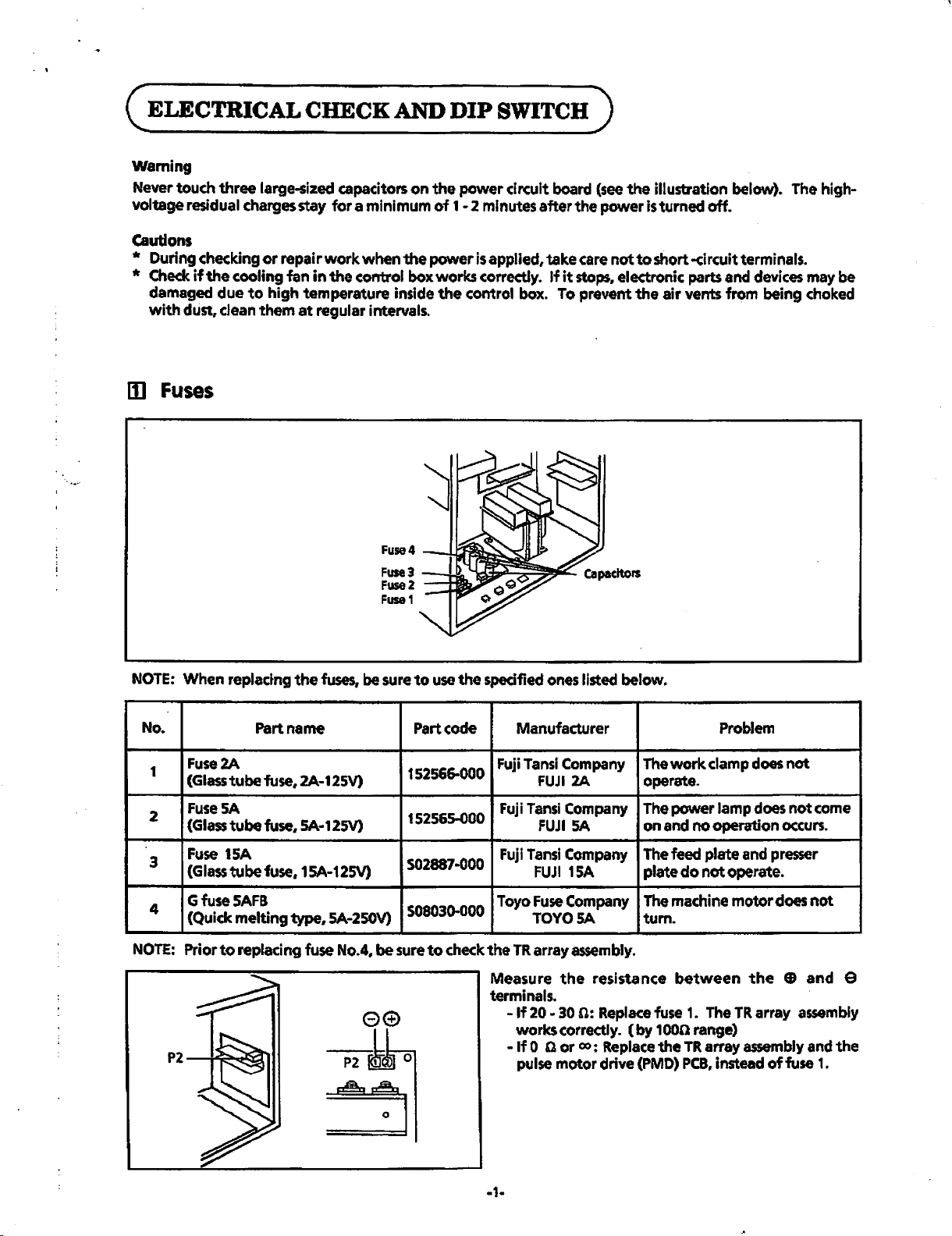
II1
Fuses
or
repair
work
when the power
fan
in
the
control box works correctly.
to
high temperature inside
at
regular intervals.
Fuse4
Fuse3
Fuse2
Fuse1
is
applied, take
the
control box. To prevent
-+-Bh
board
If
it
stops.
(see
the illustration below).
care
not
to
short -circuit terminals.
electronic parts and
the
air vents from being choked
The
devices
high-
may be
NOTE:
No.
1
2
3
4
NOTE:
When replactng
Part name
Fuse2A
(Glass tube
Fuse
(Glass tube
Fuse
(Glass
GfuseSAFB
(Quick melting
Prior
fuse,
SA
fuse,
15A
tube
fuse,
to
replacing fuse
the
fuses,
2A-125V)
SA·12SV)
15A-125V)
type,
SA-2SOV)
No.4.
be
sure
be
to
use
Part code
152566-000
152565-000
502887·000
508030-000
sure
to
check
the
specified
Fuji
Fuji
Fuji
Toyo
the
Measure
terminals.
ones
Manufacturer
Tansi
FUJI
Tansi
FUJI
Tansi
FUJI
Fuse
TOYOSA
TR
array
- If 20 -
works correctly.
-
If
0 Q or
pulse
listed below.
Company
2A
Company
SA
Company
15A
Company
assembly.
the
resistance
30
n:
Replace
co:
Replace
motor drive
Problem
The
work
clamp does
operate.
The power lamp does
on
and
no operation
The
feed plate
plate
The
machine
tum.
between
fuse
(by 1 oon
the
(PMD)
do
1.
range)
TR
PCB,
and
not operate.
motor
The
TR
array
assembly
instead
the
array
of
not
not
occurs.
presser
does
not
EB
and e
assembly
and the
fuse
come
1.
-1-
Page 4
rzl
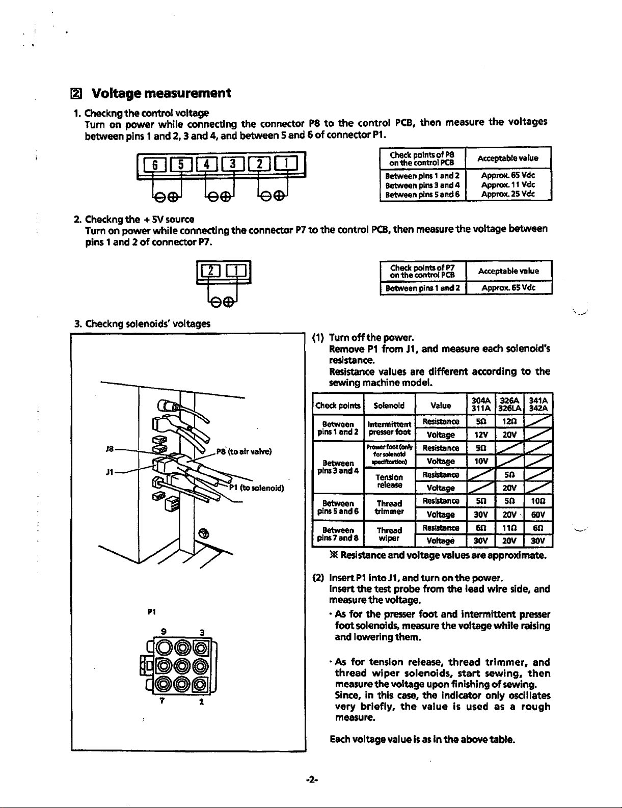
Voltage measurement
1. Checkng
ru·m
between
2. Checkng
Turn
pins 1 and 2
3.
Checkng solenoids' voltages
the
on
control
power
pins 1 and 2, 3
the
+
on
power
of
voltage
while
SV
source
while
connecting
connector P7.
connecting
and
4, and
the
the
connector
between
connector
5 and 6
P7
P8
to
the
of
connector P1.
to
the
control
(1) Turn
Remove
control
off
PCB,
the
P1
PCB,
Check
on
the
Between
Between
Between
then
Check
on
the
Between
power.
from
then
points of
control
pins 1 and
pins 3 and
pins
measure
points
control
pins
J1,
and
measure
P8
PCB
2
4
5 and 6
the
of
P7
PCB
1 and 2
measure each solenoid's
resistance.
Resistance values are different according
sewing machine model.
Check
points Solenoid Value
Between Intermittent
pins1
and2
presser foot
Proslerfoot(Oftly
forsolennl
Between
pins3and4
Between
pins5and6
Between
pins7and8
)&(
tpedfb11oct)
Tension
release
Thread
trimmer
Thread
wiper
Resistance and voltage values
Resistance
Voltage
Resistance
Voltage
Resistance
Voltage
Resistance
Voftege
Resistance
Voltage
:;?'
~
the
voltages
Acceptable value
Approx.
Approx.
Approx.
65
11
25
Vdc
Vdc
Vdc
voltage between
Acceptable value
Approx.
304A 326A 341A
311A
50
12V
50
10V
50
30V
60
30V
are
65
Vdc
to
the
342A
326LA
12n
~
_/"
20V
./'
~
./'
~
50
_/"
20V
~
100
sn
20V · 60V
110
20V
60
30V
approximate.
...
_.,.,.
P1
1
(2) lnsertP1
Insert
intoJ1,andturnonthe
the
measure the voltage.
•
As
for
the
foot
solenoids, measure
and
lowering
·As
for
tension
thread
measure
in
Since,
very
briefly,
measure.
Each
voltage value is
·2-
power.
test
probe
from
the
lead
wire
side,
presser foot and intermittent presser
the
voltage
while
them.
release,
wiper
solenoids,
the
voltage upon finishing
this
case,
the
the
value
as
in
thread
start
indicator
is
used as a
the
above
trimmer,
sewing,
of
sewing.
only
oscillates
table.
and
raising
and
then
rough
Page 5
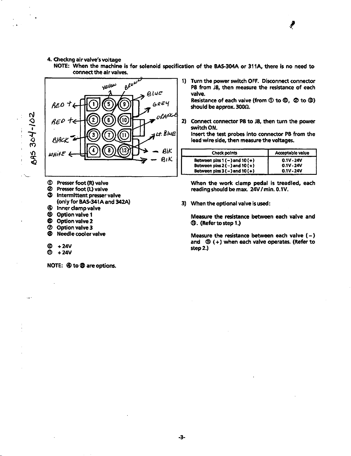
4. Checkng
NOTE:
(J)
Presser
e
Presser
air
valve's
When
the
connect the
foot
(R) valve
foot
(L) valve
voltage
machine
air
valves.
G Intermittent presser valve
(only
for
BAS-341A
and
342A)
® Inner clamp valve
$ Option valve 1
8 Option valve 2
(/) Option valve 3
8 Needle cooler valve
~
+24V
®
+24V
is
for
solenoid specification
of
the
BAS-304A
1)
Turn
the
power
P8
from
J8,
then measure
valve.
Resistance
of
each valve (from (t)
should be approx. 3000.
2)
Connect connector
switch
Insert
lead
When
reading
3)
When
Measure
®. (Refer
Measure
and ® (
ON.
the
test probes
wire
side, then measure
Check
points
Between pins 1
Between pins 2
Between pins 3
the
(-}and
(-)and
(-}and
the
work
should be max. 24V I min. 0.1V.
optional valve
the
resistance between each valve and
to
step 1.)
the
resistance between
+)
when
step2.)
or
switch
P8
10 C
10 C
10 (
clamp
311A, there
OFF.
Disconnect connector
the
to
J8,
into
connector
the
+)
+)
+)
pedal is
Is
used:
resistance
to$,
then
turn
voltages.
Acceptable
treadled,
is
no
P8
0.1V-24V
0.1V-24V
0.1V-24V
each
each valve operates. (Refer
need
of
each
e
to~)
the
power
from the
value
each
valve
to
(-)
to
NOTE:
@to
8 are options.
-3-
Page 6
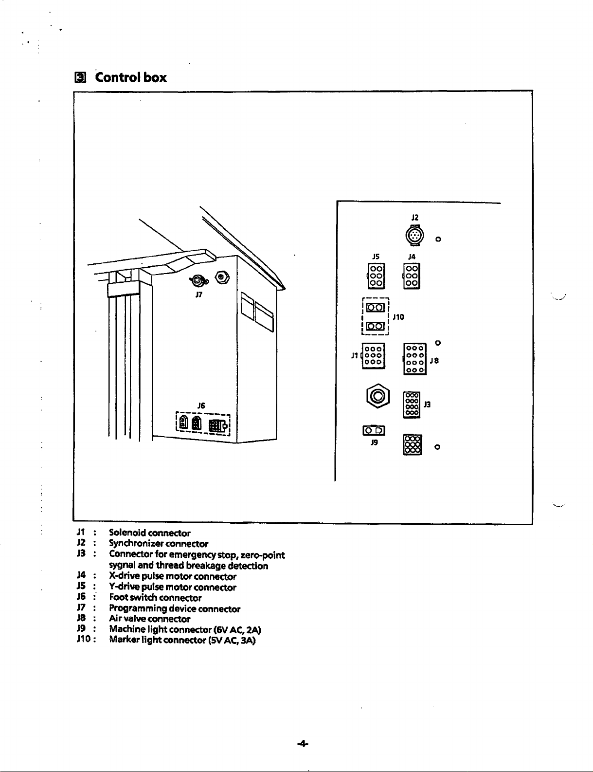
Ill Control box
~0
JS
J4
~~
r---.,
lra:QJI
: 1
~Kmlr
'"---.J
J1
s1o
J2
0
J8
J6
fi~---~
_____
"----
J1
J2
J3
J4 X-drive pulse
JS
J&
J7
J8
J9 Machine light connector (6V AC. 2A)
J 1 0 :
Solenoid connector
Synchronizer connector
Connector for emergency stop, zero-point
sygnal
and
thread
Y-drive pulse
Foot switch connector
Programming device connector
Air
valve connector
Marker
light
breakage
motor
connector
motor
connector
connector
,
•.
detection
(SV
AC,
3A)
lool
J9
Page 7
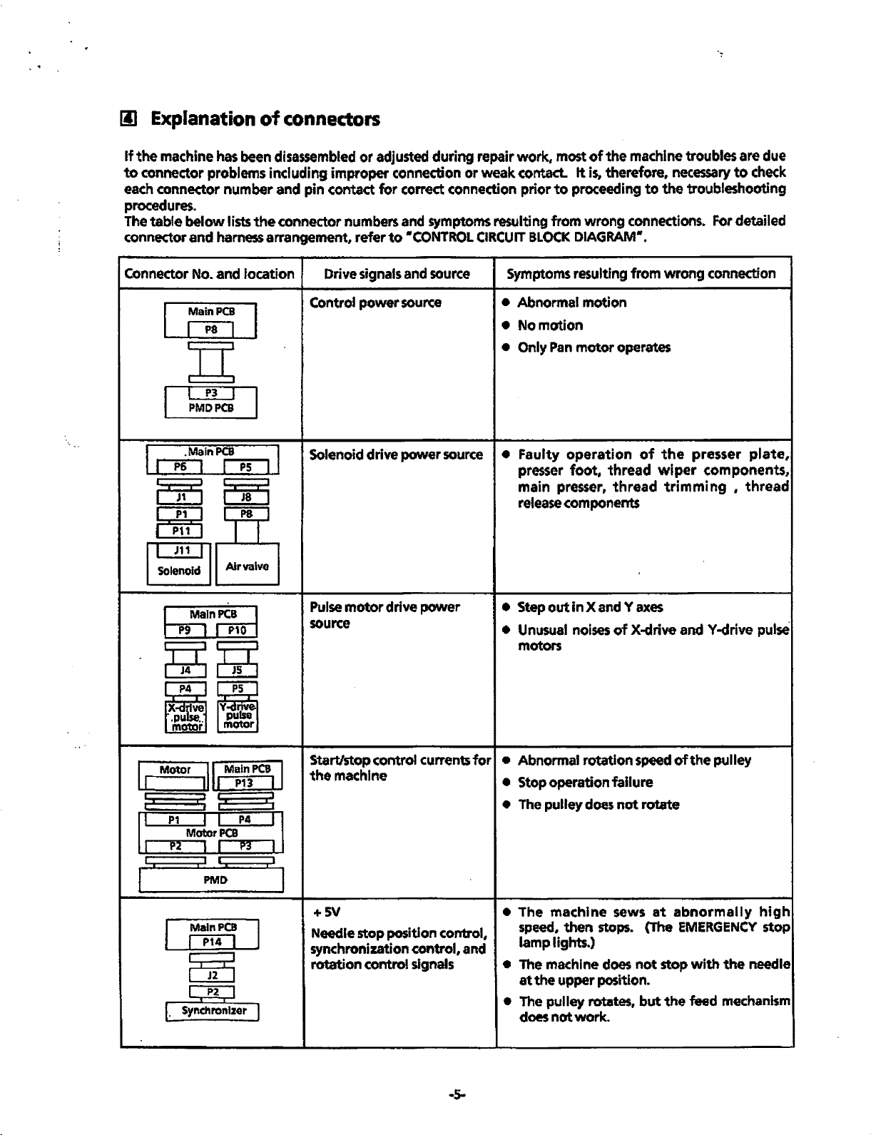
Ill
Explanation
If
the
machine
to
connector problems including improper connection
each connector number and pin contact
procedures.
The
table
connector and harness arrangement, refer
has
below
of
connectors
been disassembled
lists
the
connector numbers and symptoms resulting
or
adjusted during repair work, most
for
correct connection prior
to
•coNTROL
or
weak contact.
CIRCUIT
to
from
BLOCK
of
the
machine
It
is,
therefore,
proceeding
wrong
DIAGRAM•.
connections. For detailed
troubles
necessary
to
the troubleshooting
are
to
due
check
Connector No. and location
Main
PCB
I P8 I
I P3 I
PMDPCB
.MainPCB I
I
P6
I
I I
PS
Solenoid drive power
I
m [5[5
ElBg
I J11 I
Solenoid
~In~
~~
Air
PS
Y
nlsve.
pu
motor
valve
a
Drive signals and source
Control
Pulse
source
power
motor
source
drive
power
source
Symptoms resulting from wrong connection
• Abnormal motion
•
Nomotion
• Only Pan
•
Faulty
presser
main
release components
• Step out
• Unusual noises
motors
motor
operation
foot,
presser,
in
X and Y
operates
of
thread
thread
axes
of
X-drive
the
presser
wiper
components,
trimming ,
andY-drive
plate,
thread
pulse
Motor
-[ L
I
;.
1:
I I I
I
ll
Main
PCB
·I
P13
I:
:I
I:
:~M+r:
1
PMD
Main
PCB
I P14 I
I I
Start/stop
I
the
LJ
:1
I
I
+SV
Needle stop position control,
synchronization control, and
rotation control signals
control currents
machine
~
P2
I
Synchronizer
r.
I
l
..
s-
for
• Abnormal rotation speed
• Stop operation failure
• The pulley
• The
speed,
lamp
• The machine does
at
the
• The pulley rotates,
does
does
machine
then
stops. (The EMERGENCY
lights.)
upper position.
not
work
not
sews
.
rotate
at
not
stop with
but
the
of
the
pulley
abnormally
the
needle
feed mechanism
high
stop
Page 8
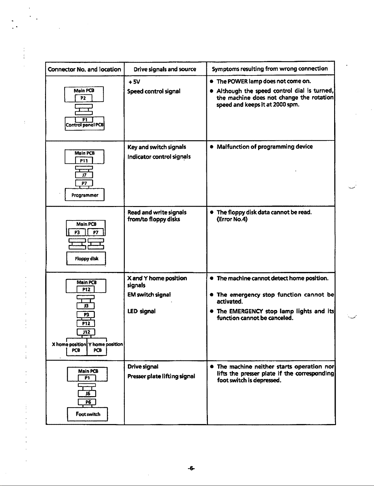
Connector No. and
Main
PCB
[PO
f I
P1
panel
Main
em]
l J
PCB
1control
location
PCBJ
Drive
signals and
+SV
Speed control signal
Key and switch signals
Indicator control
source
sig~ls
from
does
wrong
not
come on.
Symptoms resulting
• The
•
Although
POWER
lamp
the
speed <ontrol dial is
the machine does riot change the
speed and keeps
•
Malfunction
it
at
2000
of
programming
spm.
connection
turned,
rotation
device
· I Programmer
MainPCB
IIP31
I
86
I
Floppy
Main
Qifl
~
~
r
I . . h I
Xh
ome
position Y
I
PCB
Main
QCJ
,,2
T T
P7
disk
PCB
1
PCB
PCB
ome
~
.J
II
I
..
positiOn
i
Read
and
write
from/to
X
signals
EM
LED
Drive signal
Presser
floppy
andY
home
switch signal
signal
plate
signals
disks
position
lifting
signal
•
The
floppy
(Error No.4)
• The machine
• The emergency
activated.
• The
function
• The machine
lifts
foot
disk data
cannot
EMERGENCY
cannot
neither
the
presser
switch is depressed.
cannot
detect
home
stop
function
stop
lamp
be canceled.
starts
plate
If
the
be
read.
position.
cannot
lights
and
operation
corresponding
be
its
nor
Page 9
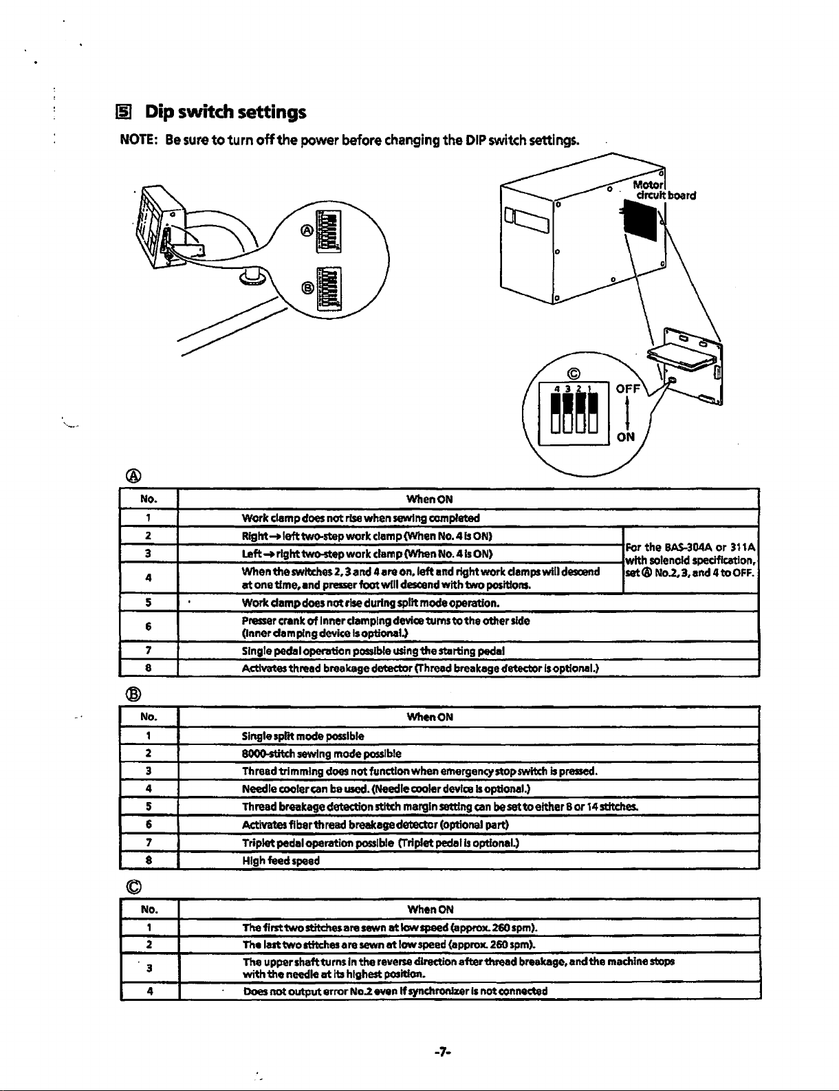
liJ
Dip switch settings
NOTE:
®
No.
1
2
3
4
5
6
7
8
Be
sure
to
turn
off
the
power
before
Work clamp
Rfght..,.lefttwo-stepwork clamp (When
Left~
When the
at
one timer and presser foot
Work clamp does
Presser
(Inner damping
Single pedal operation
Activates thread breakage detector
does
not
rise when sewing
right two-step work clamp (When No.
switches
crank
2, 3 and 4 are on. left
not
rise
during
of
Inner clamping
device
Is
optional.)
possible
changing
When
will
descend
split
mode
device
turns
using
the st.rting pedal
(Thread
the
DIP
ON
com
plated
No.4
fs
ON)
41s
ON)
and
right work
With
two
operation.
to
the other
breakage detector
switch
settings.
ct::::J.
clamps
side
will
Is
optional.)
positions.
0
descend
Fer
the
BAS-304A
or
311A
with solenoid spedfication,
set®
No.2~
3#
and 4
to
OFF.
No.
1
2
3 Thread trimming
4
5
6
7
8
Single split
8000-stitch sewing mode
Needle cooler
Thread breakage detection stitch margin setting
mode
Ad:ivates fiber thread breakage detector (optional part)
Triplet pedal operation
High
feed
speed
possible
possible
does
not function when
can
be
used. (Needle cooler
possible
When ON
{Triplet
©
No. When
,
2
3
4
The first two stitches are
Thelalttwo
The
with
Does
stitches are
upparshaftturns
the
needle
at
its highest position.
not
output
error
In
No.2 even
sewn
sewn
the
at
low
at
low
reverse
If
synchronizer
emergency
device
pedal
ON
speed
(approx.
speed
(approx.
direction afterttvead breakage, and the
stopswitd1
Is
optional.)
can
be
set
is
optional.}
260
260
Is
notconnocted
to
spm).
spm).
is
pressed.
either 8
or
14
-7-
stitches.
machine
stops
Page 10
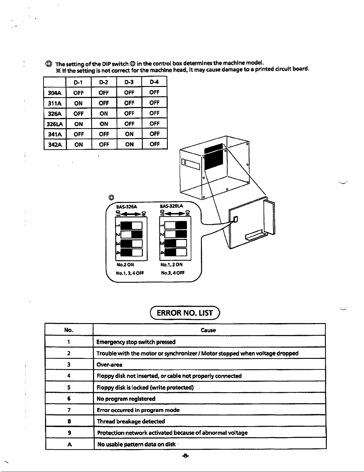
@
The
setting
*
If
the setting
of
the
is
DIP
switch@ in
not
correct
for
the
control box determines
the
machine head,
It
may
the
machine model.
cause
damage
to
a printed circuit board.
0-1
304A
311A
326A
326LA
341A
342A ON
OFF
ON
OFF
ON
OFF
D-2
OFF
OFF
ON
ON
OFF
D-3
OFF
OFF
OFF
OFF
ON
D-4
OFF
OFF
OFF
OFF
OFF
No.
1
2
3
4
5
6
7
8
9
No.2
0N
No.1,
3,4
OFF
Emergency
Trouble
Over-area
Floppy disk
Floppy disk
No program registered
Error occurred
Thread breakage detected
Protection network activated
stop switch
with
the motor
not
inserted,
is
locked (write protected)
in
program
No.1,20N
No.3,40FF
(
ERROR
pressed
or
synchronizer I
or
mode
cable
because
NO.
LIST)
Cause
Motor
not
properly connected
of
abnormal voltage
stopped when voltage dropped
A
No
usable pattem data on
di'k
·
Page 11

(TROUBLESHOOTING)
1
2
3
4
Indicates manual operation.
Indicates
\,_____,/
Selects
a
appears
determination and solution table".
the
yes-or-no
Indicates
swltch
in
operation.
course
of
dedsion-making
that
the
procedure
the
first column
action
to
follow, using
process.
to
follow
of
•problem
5
6
7
D
0
-9-
Indicates
Indicates
appears
Indicates turning-off
wtting-up
that
on
the next
the
operation.
procedure
page.
of
the
power switch.
to
follow
Page 12

Powering-up
sequence
L
Tum
Insert
on
POWER
switch.
the
floppy
disk.
No
.,
_
_...'
Floppy
disk
insertion
1+----------------\
Press
the
PRO
NO.
switch, then press
the
RNi switch.
No
Yes
TurnonPOWER
switch.
-10.
Page 13

Presser
and
presser
plate
operation
Set cassette or
material
to
~==-----------_1
TumonPOWER
No
be sewn.
No
switch.
Shifting
to
the
sewing
start
position
No
Yes
No
Input
sewing data.
Page 14

No
No
Input sewing data
and
shift
to
sewing start position.
the
·._...
Test
Yes
--·
No
No
-12-
Page 15

No
Yes
Input sewing data
and
shift
to
sewing start position.
the
Sewing
operation
No
No
No
No
-13-
Page 16

No
No
ln~t
sewing
and start
operation.
data
se'Ning
-~-·
Emergency
stop
and
restarting
operation
No
No
·14-
Page 17

.......
No
Programming
device
-15-
Page 18

c
PROBLEM
DETERMINATION AND SOLUTION )
Precautions
1.
Be
sure
to
tum
2.
the
power
When
replacing a fuse,
the power switch
cord.
be
sure
to
OFF
before opening
use a
new
Problem determination and solution table
• Prior
• l-etters marked
NO.
FLOWCHART
ERROR
#1
The
will
the
isturMd
to
proceeding
-no
fuse has
-each
those items should be checked
IN
CHAPTERS
STATUS
POWER
not
light
POWER
plug is correctly inserted.
AND
lamp
when
switch
ON.
to
the
following
blown
with
an asterisk (e.g. (a)*) in
PROBABLE
1.
Power cord
defective
d~2
__liiiRIII
[n:l®
~
table,
while
the
CAUSES
~
~
311
check
power
(a)* Measure voltage between taps 20 and
I I
2.
Fuse
3.
Power
defective
blown
PCB
.PI
Remove fuse No.2 and check
continuity.
the
(a)*Unplug connector
NOTE:
~
Main
4.
circuit board
defective
1
2
P7~
(a)*Unplug connector
the
one having
the
is
·CHECK/
21
Make sure
matches
fuse.
board,
the
that
ct·IECK
applied.·
ADJUSTMENT I REPAIR
on
transformer
that
the
If
there
turn
the' voltage.
the
contrOl
lnsertatesterprobe
connector
board, tum
the
voltage
the
control
control box cover
same
quality
I
ADJUSTMENT I REPAIR
in
control box.
the
measured voltage
specification.
is
no
continuity, replace
P8
~er
it
is not
is
defe
P7
power
the
PCB.
board
of
ON,
~rox.
the
lead
of
ON,
the
If
box
from
the
on
circuit
or
and capacity
it
for
the
main circuit Power
then
10
ve.
intothe
wire
the
main circuit
then
If
it
is
not + 5V,
Is
defective.
plugging
as
column indicate
measure
VDC,
side.
measure
in
I unplugging
the
old
one.
that
REPLACEMENT
PARTS
Power cord
Glass
tube
fuse
SA
PCB
Maindrcuit
board
··
...
~·
5.
Panel
drcuit
#2
If
the
RJW
pressed,
indicator
the
floppy
drive
(FDD)
not
light
FDD does
the
floppy
data.
switch is
the
lamp
disk
does
and the
not
read
disk
on
defective
1.
Connector contact
defective
2.
Main
circuit board
defective
board
Check
drcuit
circuit board.
Oleck
contacts between connector
circuit board and
between
circuit
(a)
Tum
switch
intermittent!~
~ain
bUzzer does
manner,
·defective.
(b)
St~
H e presser plate
normally,
defective.
the
connection between
board
and connector
the
connections, harnesses, and
the
connectors
board and
the
power
to
check
tochec
the
on
the
P3
the
ON, and press
If
Then press
if
the
not
operate
control
presser
the
control circuit board
P2
panel circuit board and
or
P7
FDD.
the
buzzer sounds
buzzerst~
drcuit
ce
not
-16-
the
panel Panel
of
the
main board
pin
P2
of
the
main
of
the
main
the
EM
the
button
If
in
sucn
a
board is
lifter switch.
work
Is
drcuit
Maindrcuit
board
the
Page 19

NO.
IN
CHAPTER
FLOWCHART
ERROR
STATUS
8
AND
PROBABLE
CAUSES
CHECK/
ADJUSTMENT I REPAIR
REPlACEMENT
PARTS
#2
If
the
RIW
switch is
pressed,
indicator lamp on
the
drive
not
FDD
the
data.
#3
After a few
seconds
R/W
pressed,
code appears
the
the
floppy disk
(FDD)
does
light
and
does
floppy disk
switch
ERROR
the
not
after
is
an error
display.
read
the
on
#4
The
presser
will
not
the
presser
lifter
stepped on.
rise when
plate
switch
plate
is
3.
Presser
switch defective
4. Floppy disk
(FDD)
1.
Floppy disk
defective
2.
Floppy disk drive
(FDD)
3.
Main
1.
Fuse
2.
Power
defective
plate
defective
defective
PCB
defective
blown
PCB
lifter
drive
(a)
If
the
presser
operates just
without
presser
Unplug connector
(b)
press
and
operates normally, the
lifter
switch
Replace
Chec:k
ERROR
disk.
normally read, t e old floppy
defective.
Check
ERROR
Replace
(a)
(a)*Turn the power
the
If
error code No.4 appears on
indicator.
If
the
if
error code No.4 appears on
indicator.
the main
Remove
continuity.
replace
of
the control
measure
65
VDC,
plate automatically
byturningthe
any other operator action, the
plate
lifter
switch
P6
of
the
RMI switch.
presser
is
defective.
FDD.
If
yes,
insert other floppy
newl~
inserted
If
PCB.
fuse
No.3
If
there
the
fuse.
PCB
the voltage.
the power supply
flo~y
yes,
replace the
and check
is
no continuity,
ON
while connector
is
plugged, then
If
power on
is
defective.
the
control box
If
the machine
plate
disk
tsk
is
it
for
it
is
not
Is
defective.
the
is
the
FDD.
P8
approx.
Presser
lifter switch
assembly (2-
stage switch)
FDD
Floppy disk
FDD
Main
Fuse
(1SA)
Power
plate
PCB
No.2
PCB
~
3.
Presser
switch and its cable
defective
7 1
r.::::;;::;;:;, : l Switch)
~
~/..:
For
342A)
4.
Main
I'T'\
~~
plate
lifter
.------,
(First
rt:=
1..:
,
~
I Presser
• : (Second
!l:J_;
P6
pneumatic specification
PCB
Switch)
"c.J
Start
defective
~-
@@l@
9
i©©>®
IQ)@@
©@lQI4
12
J8
{a)
UnplugconnectorP&ofthecontrol box,
then check
If
the
followl ng specified value,
plate
defective:
oa
lifter
released, respectively.
(BAS-304A,
(a) Refer
(b) Step on
while pressing
If
an error code appears on
indicator,
(c)* Unplug connector
tum
voltage
switch.
between pins 1 (-) and 1 0
between pins2 (·)and 10
is
defective.
it
for
measured
lifter
switch or its cable
or
oo 0 when the
switch
311A, 314A,
to
#2, 2(a).
the
presser
STEP
the
main
the
power
on
J8
while stepping on
If
it
is
not
continuity.
value
is
not
is
ON.
presser
stepped on
31
plate
BACK
PCB
is
P8
of
the
then measure
approx. 24
the
the
presser
is
or
SA,
326A,
lifter
switch
switch.
the
not
defective.
control box.
VDC
(+),and
(+),main
plate
326LA,
ERROR
the
the
start
PCB
Presser
lifter
assembly
cable
Main
plate
switch
341A, and
PCB
or
Its
-17-
Page 20

NO.
IN
FLOWCHART
ERROR
#4
The presser plate
will
the presser plate
lifter switch
stepped
CHAPTER
AND
STATUS
not rise when
is
on.
8
5.
PROBABLE
CAUSES
AJ
r valve defective
1(QJ@©
@©(QJ
(Q)@(Q]
9
[9
(a)
CHECK/
Unplug
then
If
it
is
ADJUSTMENT I REPAIR
connector
P1
of the control box,
measure the resistance.
not
approx.
400
0 between pins 1
and 10. and between pins 2 and 10,
air
valve
is
defective.
the
.
REPLACEMENt
PAR15
Air
valve
:1
··".
'·
·,
~
4[Q)©©
P1
For
solenoid specification
4.
Mafn
PCB
12
defectiv~
+
3 9
~00
00~
0
1
P1
S.
Air valve defective
9
7
-
3
000
[ooo
(BAS~304A
(a} Refer
(b) Step on the presser plate
while
If
. indicator,
(c)*
Unplug
tum
and 311A)
to
#2,
2(a).
pressing
an error code appears on
on
the
STEP
BACK
the
main
PCB
connector
P1
of
power, then measure
voltage of J 1 while stepping
switch.
between pins 3
circuit board
(a)
Unplug connector
If
It
is
not approx.
(+)and
Is
defective.
P1,
then measure
resistance.
If
it
is
not approx. s ohms between pins 3
and 4, the solenoid
is
defective.
lifter
switch
switch.
the
is
the
ERROR
not defective.
control box,
the
on
the
start
10
VDC
4 (·),the main
the
Main
Air
PCB
valve
000
7
1
-18-
Page 21

' .
;.
·~--
NO.
IN
CHAPTER
FLOWCHART
ERROR
STATUS
#5
The
presser
will
not lower
when the
plate lifter switch
is
stepped on. once lowered by stepping on the
#6
The
presser
will
not
return
its home position
when the start
foot switch
stepped on.
AND
plate
presser
plate
to
Is
8
PROBABLE
1.
Presser
plate lifter
switch defective
1.
Start
foot
and
its cab I e
defective
~1~
P6
CAUSES
switch
(First
: Presser
r
!(Second
J
Switch)
Start
CHECK/
If
the
presser
rises
when the power
respectively,
action
to
lifter
switch
plate
lifter
presser
(a)
plate lifter switch
If
nothing shifts
P1
of
connedorsJ&andP&oftheconttolbo~
(b) Unplug connector
then
measured
following specified
switch or its
when
ADJUSTMENT I REPAIR
plate automatically lowers
is
turned
without
the machine, the
is
switch
any
defective.
rises
by
other operator
presser
If
the
releasing
Is
at
all, reinsert connector
the main circuit board
P6
of
check
it
for
contl nuity.
value
Is
not both the
values,
cable
is
defective:
the
start foot switch
respectively.
OFF
or
ON,
plate
or
presser
plate
presser
it,
the
d~fective.
and
the control
If
box,
the
the start foot
co
0
or
00
is
off
or
on,
REPLACEMENT
PARTS
Presser
plate
lifter switch
assembly
(2-stage
switch)
Start
foot
switch
2.
Home position
signal error
3.
Fuse
blown
(a)
If
the
direction
home position
Reinsert
(b)
presser
plate
and
moves
its motion
signal
is
connector P12
incorrect.
of
circuit board, connectors
the control
P12
(c)
Press
of
box,
and
connectors J
the machine
head.
EMERGENCYSTOPswitchtwice,
then operate the feeding
hand.
If
the
LED
on the home position
PCB
does not flicker when the feeding
mechanism
approaches
the
position, the home position signal
incorrect.
Check
if
the
sensor
(d)
position
PCB
is
the
sensor
(e)
Oean
Remove
fuse
continuity.
the
fuse.
sensor)
subject
from the light.
X-axis
No.3,
If
there
(particularly,
on the home position
to
any light.
home position dog.
then
check
is
no continuity, replace
in the
is
reverse
erratic, the
the control
J3
and
P3
12
mechanism
home
Y-home
If
yes, protect
it
for
of
and
is
by
Home
PCB
Fuse
position
1SA
-19-
Page 22

••
olo•
• • • I
....
l ~ •
l\
• ·,
_.,-·~~~~-:~~-
.
. )
.J
/
~
.t.'+·
i
'\~·
\.
-~:
..
. •
Page 23

NO.
IN
CHAPTER
FLOWCHART
ERROR
:f/:6
The
presser
will
not
AND
STATUS
plate
return
to
its home position
when the start
foot
switch
stepped on.
is
8
PROBABLE
4.
PowerPCB
defective
5.
Pulse
cabl~ve
CAUSES
motor
or
1
fQJ@
4
©><QJl9
3
[Q)
(Q)
6
CHECK I ADJUSTMENT I REPAIR
Refer
to
#4, 2(a)*.
Unplug connector P4and
its
box,
then
measure
approx. 0.5 n between
between pins 1 and
and between pins 4 and 6, the pulse motor
or
its cable
is
defective.
PS
the
resistance.
pins
1 and
3,
between pins4and
from control
If
it
is
2,
not
5,
REPLACEMENT
PARTS
Power
PCB
Pulse
motor
assembly
#7
The
presser
shifts
to
its home
position,
error
appears on
ERROR
then
code
indicator.
#8
The
presser plate
will
not
shift
the
sewing start
position.
#9
The
TEST
lamp will
not
light
when
TEST
switch is
pressed.
plate
No.3
the
to
the
6.
Main
circuit board
defective
1.
Floppy disk
defective
1.
Floppy
defective
2.
Main circuit board
defective
1.
TEST
cable defective
A 1
I I
ld
II
II
Bl
disk
switch
r-,
It
1111111
lllll1llll
or
Replace
If
overloaded with sewing programs.
error
the
main circuit board.
code
No.3 appears,
Insert another floppy
functions normally
floppy
Replace
Its
Unplug connector
board, then
harness
measured
Al3
specified values,
defective;
Between pins
813
co 0
swings when
dis~
the old floppy disk
the
connector for continuity.
value
or
the moment the indicator needle
with
main circuit board. Main
P2
check
the
is
not
the
B1
(-)and
the
the
floppy disk
disk.
If
the machine
the
newly
inserted
Is
defective.
of
the
control
operation panel board
both
the following
drcult
If
the
panel circuit board
810
( + ): normally
TEST
switch
Is
on.
is
is
Main circuit
board
Floppy
disk
drcuit
board
Panel
circuit
2.
Test
#10
No
feeding
operation occurs
during
the
test.
lamp or its
cable defective
AI
le
~
IIIII
Bl
3.
Main circuit board
defective
1111111
Unplug connector
board, then
A7 ( + ) and A3
hamess connector.
indicate
magnified ohm range, the panel circuit
Al3
board
813
Replace
Refer
PROBABLE
check
(-)of
some
value
Is
defective.
the
main circuit board.
to
#6,
Nos.1,
CAUSES
-20.
P2
of
the control circuit
continuity between pins
the operation panel
If
the tester
with
3,
column •
the
maximum
4,
5,
does
and 6
not
in
the
Panel
circuit
board
Main circuit
board
Page 24

NO.
IN
CHAPTER
FLOWCHART
ERROR
STATUS
#11
Rapid feed can
be
used
during
test.
8
AND
not
the
PROBABLE
1.
Presser plate
switch and its cable
defective
CAUSES
lifter
Refer
CHECK/
to
#4,
ADJUSTMENT I REPAIR
3.
REPLACEMENT
PARTS
#12
The
machine does
not
operate
programmed
during
#13
The
machine will
not
sew.
#14
The machine
operates
speed and
stops
while
an error code.
as
the
test.
at
high
then
suddenly
displaying
Feeding mechanism
not
adjusted. smoothly by hand.
1.
Cable defective Check
2.
Main
circuit board
defective
3. Power module
short-drculted
1. Synchronizer
or
cable defective
Adjust
Refer
PROBABLE
the
circuit board.
If
ERROR
drcuit
If
indicator and
power
(a)
Its
(b) Replace
the
to
#6,
continuity
main circuit board and
error code No.2
indicator, check voltages on
board.
error
code No.2 appears
module is short-circuited.
Check
circuit board and connectors
the
control box are correctly connected.
If
not,
feeding mechanism
Nos.1, 3, 4, 5, and 6 in
CAUSES
if
connector P14
correct
the
column .
between connector
does
the
fuse No.4 is blown,
the
synchronizer.
P4
not
appear on
on
of
connections.
to
of
the
the
move
the
P13
the
PMD
the
the
ERROR
the
main
J2
and
of
main
P2
of
Main
circuit
board
PMDdrcuit
board
FuseSAFB
Synchronizer
assembly
#15
The
machine
operates
presser
but
the
plate does
not.
#16
The thread can
be
cut.
Synchronizer
cable defective
1. Synchronizer
not
cable defective
2.
Main
defective
5~0]
a
or
its
or
circuit
board
3
IOOO
lc
t.2_
o
I
Refer
to
NOTE:
Refer
Its
9
to
(a)*While inserting
let
the
trimming
voltages between pins 5 (
(for thread
between pins 3
release solenoid: BAS-326A and 326LA
only) from
tester does
board
1
-21-
#14.
If
the
machine
status,
the
normally performed.
#1
5.
machine perform thread
operation, and measure
trimmer
the
not
is
defective.
is
placed
test
operation
the
connector
solenoid), and
(+)and 4 (·)(for
lead
wire
oscillate,
In
+)and
side.
the
this
will
P1
tension
tfthe
main
error
be
Into
the
6 (·)
drcuit
Synchronizer
Synchronizer
Maindrcuit
J 1,
board
Page 25

NO.
IN
CHAPTER
FLOWCHART
ERROR
#16
The thread cannot
be
STATUS
cut.
8
AND
PROBABLE
3.
Threadtrimming
solenoid, main
presser solenoid
cable defective
9
5]
I 0 B
r
6 l C 0 Approx. 5 ohms
OGC
1 1
#17
The
machine does adjusted properly
not
stop
with
the
needle
at
the
upper position
after
thread
trimming. defective
#18
The machine
cannot sew
patterns as
programmed.
1.
Synchronizer
2.
Mal n circuit board
CAUSES
or
CHECK/
ADJUSTMENT I REPAIR
Unplug connector
resistance.
<Thread trimmer
P9,
then
measure
solenoid>
between pins
Sand&
Approx. Sohms 304A, 311A, 326A. 326LA
3 Approx. 10 ohms 341A, 342A
1
e....;...r.-
-----.3
<Tension release
solenoid>
only
between pins
3and4
BAS-326A. 326LA
4
not
needle stop position varies
each
time
complete, adjust
the ma<hine operation is
the
upper needle stop
at
random
If
the
signal issuing timing.
Refer
to
#12.
the
REPLACEMENT
PARTS
Thread
trimming
solenoid
assembly
Main
circuit
board
#19
The operation
not
stop if
switch is pressed.
#20
The thread cannot
be
cut
after
emergency stop
is
state
#21
The
cancelled.
STEP
the
the
BACK
will
EM
switch is
inoperative.
1.
EM
switch
cable defective
J12
1.
STEP
BACK
or
its cable
defective
Al
II
r-.
IIIIIIIIIJJ
hllllllllrlllll
~I
J Bl3
or
its
switch
Unplug connector
machine head, then
If
the
resistance is
specified values,
defective;
Between pins 1 and 3:
when
respectively.
Between pins 2 and 3: co Q
when
respectively.
Referto#16and
Unplug connector
board,
then
measured value is
specified resistances,
is
I
defective.
Between pins B 1
normally co 0
needle
switch is
Al3
the
EM
the
EM
check
swings
ON.
P12
check
not
the
EM
switch
switch
#17.
P2
it
for
not
the
(·) and
the
moment
when
from
J12
of
the
it
for
continuity. assembly
the
following
switch assembly
0
nor
co 0
is
OFF
or
ON,
oro
n
is
OFF
or
ON,
of
the
control
continuity.
the
following
panel circuit board
B9
(
+)
;
the
STEP
indicator
BACK
the
drcuit
If
the
is
EM
switch
Panel circuit
board
..._·
#22.
Sewing is
resumed.
not
Referto#12and
#13.
-22-
Page 26

NO.
IN
OIAPTER 8
FLOWCHART
ERROR
STATUS
#23
Programming
cannot be
made.
AND
PROBABLE
1.
Programmer
connector or its
cable
defective
2.
Programmer
defective
3.
Main
drcuit
CAUSES
board
CHECK/
Reattach
connector
Replace
Replace
the
the
ADJUSTMENT
I
REPAIR
REPLACEMENT
PARTS
connectors
P11
programmer. Programmer
main
P7
and
J7,
of
the control circuit
drcuit
board. Maindrcuit
and
board.
board
·23-
Page 27

(oPTIONs)
Using terminals
of
lamp and marker
(j)(Ac6V)
light
When
using
(AC4.5V).
Lamp
38E
The
lamp
(5·1
~01
*When
Marker
3!E
When
purchasing a
below.
Contact
Connector
light
purchasing a
desribed below.
Contact pin(s)
Connector(s)
the
lamp,
below is
ML651-01
pi
n(s)
use
the
connector
an
option.
lamp
P assembly)
lamp
on
the
MOLEX terminal pin (female) 1381ATL
(143548-000) 2
MOLEX3191·02R1
0 (AC&V).
market, replace
pes.
(518466-000) 1pc.
marker
light
on
the
MOLEXterminal
(143549-000)
MOLEX
4pcs.
154SP
market, replace
pin{male)
(505008-000) 2pcs.
When
the
connectors
the
1380n
using
the
of
connectors
marker
the
lamp
of
the
light,
with
marker
use
the
the
parts described
light
connector
with
the
@
parts
-24-
Page 28

The
PC
set
and
the
and switches can
PC
programmer assembly
PC
programmer
be
added
without
I······
assembly
replacing
525157-000
have
been introduced. By attaching the sequencer, the
the
control
P-ROM.
valves
.......
PCset
·I······
533257-009
Page 29

P12
J3
P3
Jt2
[it~
'
I
1------
PCB
)7
H
4P-S
P12
HEAD
-AA
t )
I)
tOP•
PU
PROGRAMMER
111
P10
121
'VPM
131
141
I
tl
P9
121
XPW
131
IGToiXB
HF-AII
foYA
-YA
PID
-YB
tXA
-XA
tW
'
-
.,
~
IUIP)
Hl5P-
Tl"T
~r
:r
,...
~UA":"::C~LO::r.1V...,-A,.......,I9l'"'l
I
:
J
... lJI.Y·B 5 P2
ca
g
AC
ll
i
lA[
....
P3
P4
lOV•A
?
iDY-ll
16
ov.;-c·
rt1
1
~==~
1:
tOY-N
1
ACtOV
~-
iHF-M.
rfr:l:rt
MAIN
MOTOR
529008
DCIN
Pt
~I""
~
~~
~,It
PCB
WYU
p:!j\j;
P5
AIR
P6
Soleaaid
POD
P?
power
r-
~
...
;:-
1
Page 30

Page 31

--r-
0
 Loading...