

Page 1
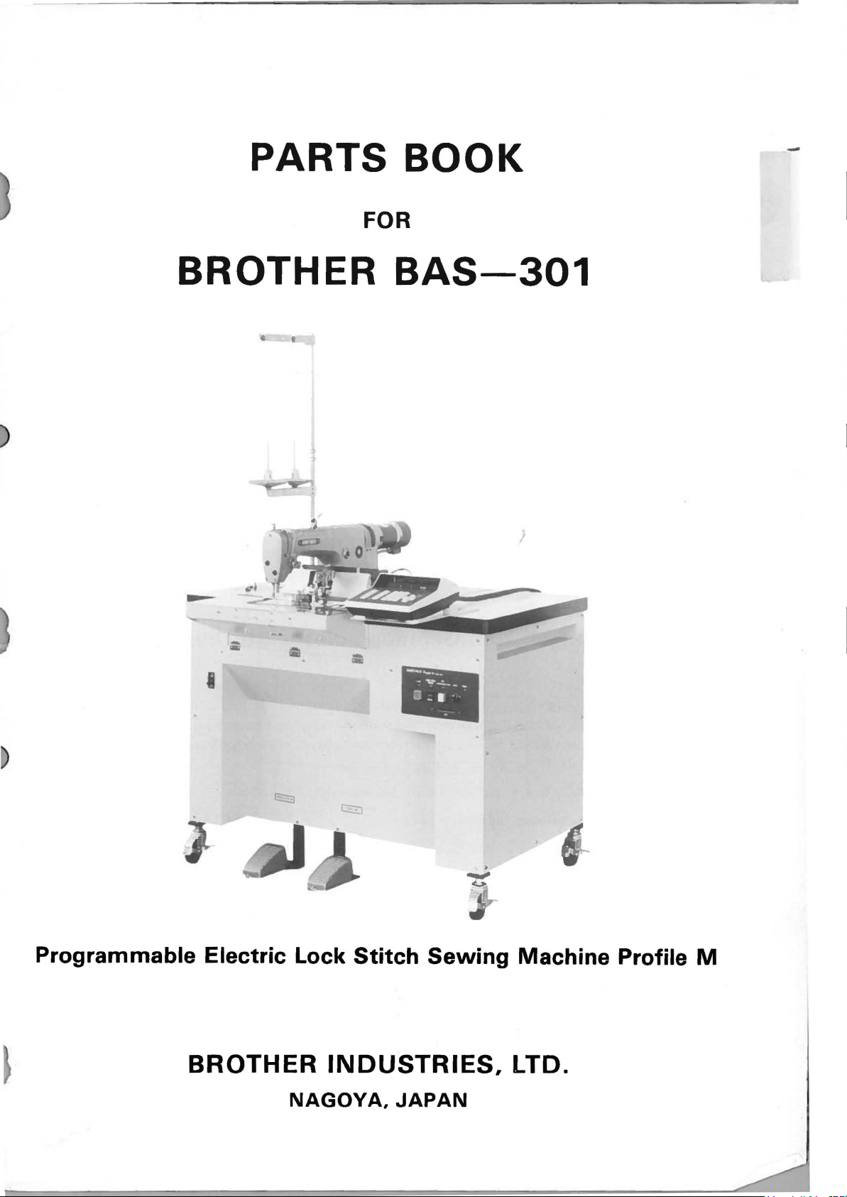
PARTS
FOR
BOOK
-
BROTHER
..,
-
I
BAS-301
Programmable
Electric
BROTHER
Lock
NAGOYA,
Stitch
INDUSTRIES,
JAPAN
Sewing
Machine
LTD.
Profile
M
Page 2
Notes
I.
If the symbol
available for supply. if, however, there
Parts can be ordered as an assembly. Please, therefore,
the
Assembly No.
2.
This book was prepared based on information available in April,
3.
Parts are subject to changes in design without prior notice.
4.
Use
this parts book together with the one for
the redundant portion.
1::;:?1
for
using this parts book
in the
"Parts
No." column indicates
is
a number in the "Assembly No." column,
082-8715.
Refer to this parts book for
that
order
the
part
is
by using the
1980.
not
The machine head used for 8AS-301
*
parts for 8715 head, which will be different depending upon the sub-classes using
8715 parts book, please see the column
is
082-8715,
of
sub-class -105.
therefore, when checking the
Anmerkungen zum Gebrauch dieses Stucklistebuches
I. Oieses Zeichen I
nicht lieferbar ist. Wenn jedoch in
steht, okann dieser Teil als ein Gerateteilsatz bestellt werden. 8estellen Sie
bitte mit dieser Geratesatznummer.
2.
Oieses
3.
ModelHinderungen sind vorbehalten.
4.
Schlagen Sie auch das Teilbuch fiir
iiberschneidet, schlag man
8uch
:;::-:-=1
basiert
in der Spalte "Teilnummer" bedeutet, daB dieser Teil
der
Spalte "GeriHesatznummer" eine Nummer
auf
den Informationen
dann
in diesem
V<?m
April, 1980.
082-8715
8~ch
nach.
nach. Wenn em Teil sich
daher
* Was der Nahmachienenkopf fiir 8AS-30 I betrifft, schlagen Sie die Spezifikation-
105
von dem Teilbuch fiir DB2-8715.
Page 3
Notes
I.
Le
etre fournie. Si, dans
Ia
toute commande, veuillez specifier
sur l'utilisation de ce manuel de pieces detachees
symbole I
piece peut etre commandee comme faisant partie d'un
:;;:-=-::J
dans
Ia
colonne "N" jeu de pees",
Ia
colo nne "N" de piece" signifie que
il
y a un numero de nomenclature,
jeu
le
n"
du
jeu
de pieces.
Ia
piece ne peut
de pieces. Done,
pour
D
2. Ce manuel a
3. Les pieces peuvent etre sujettes a des modifications sans preavis.
4. Voyez en confortant avec une livre des pieces
conferez ce livre de pieces
*
Quand
detachees de tete, cherchez 8AS-301 comme
I. El simbolo I
quiere decir que no
en
Ia columna
Por
lo
tanto, sera mejor hacer
2.
Este libro ha sido compilado basandose en los datos de que
1980.
ete fait d'apres
yous yoyez
Notas
::;;:----:1
del"Numero
le
liste des pieces
para usar este Libro de Piezas
, que
se
dispone de dicha pieza sola. Cuando, empero, hay un numero
les
renseignements valables
detachees de Modele
detachees
se
de Juego",
el
sur
un endroit repris.
par
specification dans une livre des pieces
105.
e~cuentra
pedido recurriendo al numero deljuego respectivo.
en
Ia
columna del "Numero de Pieza",
se
podra ordenar
au
mois de Avril
Ia
pieza con todo eljuego.
se
dispon'ia en Abril de
1980.
082-8715
Et
3. Las piezas quedan sujetas a cambios de diseiio sin aviso previo.
4.
Yea tam bien
duplican, refierase a este folleto de piezas.
*
Cuando
piezas del modelo
el
folleto de piezas del modelo
usted busca las piezas que difieren segun especificaciones en
082-8715,
vea las de
082-8715.
Ia
En cuanto a las partes que
el
folleto de
especificaci6n de -105 para 8AS-301.
se
Page 4
A.
B.
B.
Machine
Clamp
Clamp
Body · Presser
Mechanism
Mechanism
CONTENTS
Foot
· Knee Lifter
and
Motor
........ I
(I)............................................................
(2)
<Inner
Clamp>
.............................. 3
2
C. Feed Guide
D. Feed
D. Feed Mechanism (2) .............................................................. 6
E.
E.
F.
G.
G.
H.
Z. Accessories · Accessories Set ............................................. ....
a.
a.
INDEX
Mechanism
Table
Table
Actuator
Power
Power
Winder
Optional
Optional
..........................................................................................
Mechanism
(I)
Unite
(I).......................................................................
Unite (2)
Supply
Supply
Mechanism................................................................
.......................................................................
Mechanism
Equipment
Equipment
Parts
(1) ..................................................................
Parts
(2) ..................................................................
......................................................... 4
.............................................................. 5
............................................................. 9
Mechanism
Mechanism
(I)
.............................
(2)
.............................
10
11
12
13
14
15
16
7
8
Page 5
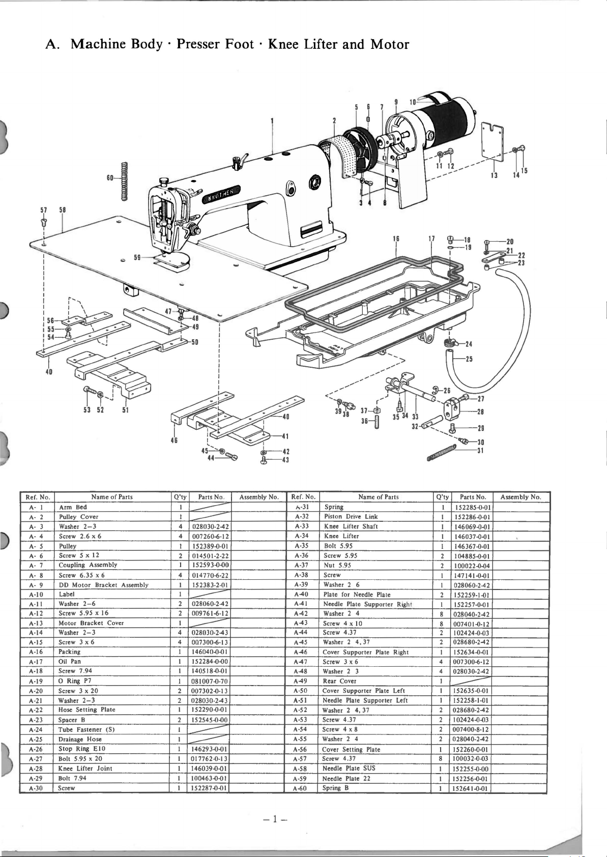
A. Machine Body · Presser Foot · Knee Lifter and Motor
-~~
11
12,-.----
----
.
1l
0
13
14
Ref
. No.
A-
I Arm Bed
A-
2
A-
3
A-
4 Screw 2.6 x 6
A-S
A-
6
A-
7
A-
8 Screw 6. 35 x 6
A-
9
A-10
A-ll
A-12
A-13
A-14 Washer
A-IS
A-16
A-17
A-18 Screw 7.
A-19
A-20 Screw
A-21
A-22
A-23 Spacer B
A-24
A-25 Drainage Hose
A-26
A-27 Bolt 5.95 X
A-28
A-29
A-30
Cover
Pulley
2-3
Washer
Pulley
Screw S x 12
Coupling Assembly
DD
Motor
Label
Washer
2-6
Screw
5.95 x 16
Motor Bracket
2-3
Screw 3 x 6
Packing
Oil Pan
94
0 Ring P7
3 x
Washer
2-3
Setting
Hose
Tube
Fastener
Stop
Ring
Knee Lifter
Bolt 7.94
Screw
51
Name
of
Parts
Bracket Assembly
Cover
20
Plate
(S)
EIO
20
Joint
Q'ty
I
I
4
4
I
2
I
4
I
I
2
2
I
4
4
I
I
I
I
2
2
I
2
I
I
I
I
I
I
I
I
I
I
45~
44~
Parts No
--
028030
-2-42
--
007260-6-12
152389.{)-01
014501-2-22
152593.{).{)0
014770-6-22
152383-2-
028060
-2-42
--
009761-6-12
028030-2-43
--
007300-6-13
146040.().()
152284.{).()0
140518-{l-01
081007.{)-70
007302.{)-13
028030
-2-43
152290.{).{)1
152545.{).{)0
--
146293.{)-01
--
017762.{)-13
146039.{)-01
100463.{).{)1
152287.{).{)1
01
I
I
~42
~43
Assembly No.
Ref. No.
h-31
A-32
A-33
A-34
A-35
A-36
A-37
A-38
A-39
A-40
A-41
A-42
A-43
A-44
A-45
A-46
A-47
A-48
A-49
A-50
A-51
A-52
A-53
A-54
A-SS
A-56
A-57
A-58
A-59
A-60
Name
ve
Link
Shaft
6
Supporter
Supporter
4, 37
Plate
of
Plate
Plate
Spring
Piston Dri
Knee Lifter
Knee Lifter
5.95
Bolt
Screw 5.95
Nut 5.95
Screw
Washer 2
Plate for Needle Plate
Needle Plate
Washer 2 4
Screw 4 x 10
4.37
Screw
Washer 2 4, 37
Cover
Supporter
Screw 3 x 6
Washer 2 3
Rear Cover
Cover
Supporter
Needle
Plate
Washer 2
Screw 4 .37
Screw 4 x 8
Washer 2 4
Cover Setting
Screw
4.37
Needle
Plate SUS
Needle Plate 22
Spring B
Parts
Rig
R1ght
Left
Left
Q'ty
Parts No.
I 152285-{l-01
152286-{l-01
I
146069.{).()1
I
146037.().{)(
I
146367-{l-01
I
2 104885.{)-01
100022.{).{)4
2
147141.{).{)(
I
I 028060-2-42
152259-1.{)1
ht
2
I 152257-0.{)1
8
028040-2-42
8 007401-{l-12
2 I 02424-0-03
028680-2-42
2
152634.{).{)(
I
4
007300-6-12
4
028030
I
~
152635-{l-01
I
I 152258-1-01
2 028680-2-42
102424.().{)3
2
2 007400-8-12
2
028040
I 152260-0-01
100032.{).()3
8
152255-{l-00
I
152256.{).()1
I
152641.{).{)(
I
Assembly No.
-2-42
-2-42
-1-
Page 6
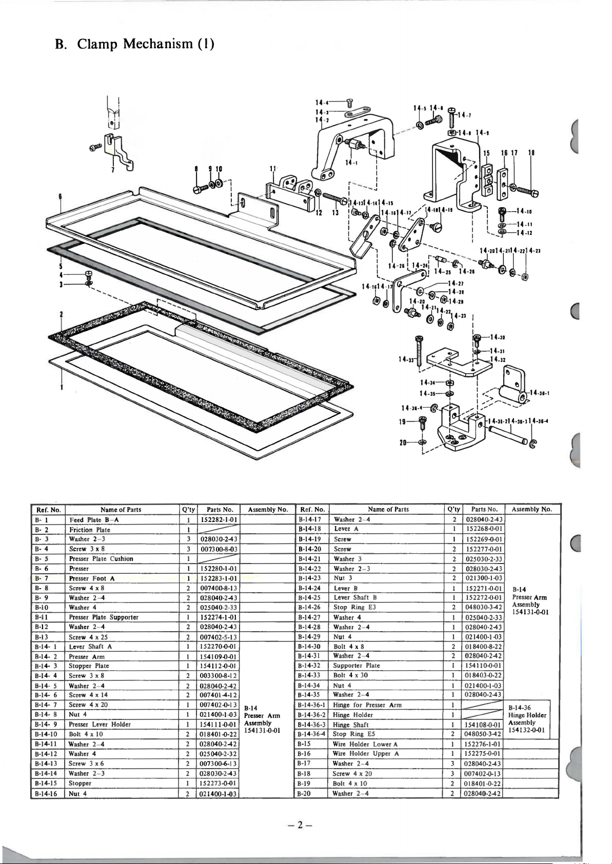
B.
Clamp Mechanism
(I)
'l~
-/~
lt'4
1!3-14
-7
-1 14-t
l
w--14-ta
i
~14-
~--.,._-14-
11
n
Q'ty
Par
of Par
Ref. No .
B· I
B·
2
B·
3
B· 4
B·
5
B- 6
B· 7
8 Screw 4 x 8
BB·
9
B-
10 Washer 4 2 025040
B·ll
B-
12 Washer 2- 4
B-13
B-1
B-1
B-1
BB-
B-14
B-14- 7 Screw 4 x 20
B-1
B-1
B-1
B-14-11
B-1
B-14-13
B-14·14
B-14-15
B-1
Screw 4 x
Le
4· I
4- 2
Presser Arm I
S
4- 3
14- 4 Screw 3 x 8 2 003300-8-12
Washer 2- 4
14· 5
- 6 Screw 4 x
4- 8 Nut 4
4- 9 Presser Lever Holder
4-10 Bolt
Washer 2- 4
Washer 4
4-12
Screw 3 x 6
Washer 2- 3 2 028030.2-43
Stopper
4-16 Nut 4
Name
e<d
Plate B- A
F
Friction Plate
2- 3 3
Washer
Screw 3 x 8
Pr
esser Plate Cushion I
Pr
esser I
Pr
esser Foot A I 152283-
Washer 2- 4
Presser Plate Supporter I
25
ver
Shaft A I 152270-0-01 B-14·30
top
per Plate
14
4x
10
ts
ts
152282-Hll
I
I
028030-2-4 3
--
3
007300-8-03
1522
80·
--
007400-8-13
2
2 028040-2-43
1522742 028040
2
007402-S-13
15
4109-0-01
I
15
411 2-0-01
2
028040.2-42
007401-4-
2
I 007
40
I 0
I
2 01840
2
2 025040-2-32
2
I 152273-0-01
2
2-0·13
21
400-1-0 3
15411
1-0-22
028040.2-42
007 3 00-6-1 3
021400-1-0 3
No. Assembly No. Ref. No.
1-0
1
1-01
-2-33
1-01
-2-4
3
12
B-14
Presser
Arm
Assembly
1-0-01
154131
-0-01
B-1
4-1
B-14·18
B-
14-1
B-14-20
B
-14-21
B-14-22
B-14·23
B-14-24
B-14-25
B-14-26
B
-14
B-14-28
B-14·29
B-1
4·31
B-14·32
B-14-33
B-14
B-1
4·35
B-14-36-1
B-1
4-36-2
B-14-36-3
B-1
4-36-4
B-
15
B-16
B-1
7
B-18
B-19
B-20
Name
7
Washer 2- 4
Lever A
9
Screw I
Screw
Washer 3
Washer 2- 3
Nut 3 2
Le
ver B
Le
ver Shaft B
Stop Ring
·27
Washer 4
Washer 2- 4
Nut 4 I
Bol
t 4 X 8
Washer
Supporter
X 30 I
Bolt 4
-34
Nut 4 I
Washer
Hinge for
Hinge Holder I
Hinge Shaft I
Stop Ring
W
ue
Holder Lower A
Wire Holder Upper A
Washer 2- 4
Screw 4
X 10 2
Bolt 4
Washer 2- 4
of Parts
E3
2- 4
Plate I
2- 4
Presser A
rm
E5
x 20
Q'ty
Parts No. Assembly No.
2
028040·2-43
I
152268-0-01
-0
-01
152269
152277-0-01
2
2
025030·2-33
2
028030-2-43
021300·1-03
I
152271-0-01
152272-0-01
I
2
048030-3-42
025040-2-33
I
I
028040-2-43
021400-1-03
2
018400-8-22
2
028040·2-42
154110-0-01
018403-0·22
021400-1-03
I
028040-2-43
I
--
154108-0-01
--
2
048050
·3-42
152276-1-01
I
152275-0-01
I
3
028040-2-43
3
007402-0-13
018401-0-22
2
028040·2-42
B-
14
Presser
Arm
Assembly
15
4131-0-01
B-1
4-36
Hinge Hol der
Assembly
15
4132-0-01
-
2-
Page 7
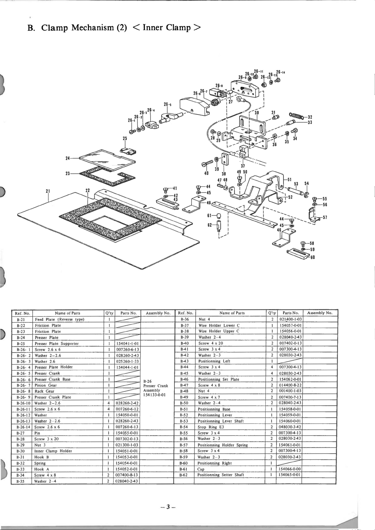
B.
Clamp Mechanism (2) < Inner Clamp >
of
Parts
Ref. No.
Feed
B-21
Friction
B-22
Friction
B-23
B-24 Presser Plate I
Presser Plate Supporter I 154041-1-01
B-25
B-26- I Screw 2.6 x 6 I 007260-6-1 3
B-26- 2 Washer
B-26- 3 Washer 2.6 I 025260 -1-
Presser Plate Holder
B-26- 4
B-26- s Presser
Presser
B-26- 6
B-26- 7 Pinion Gear I
B-26- 8
Rack Gear
B-26- 9 Presser
B-26
-10 Washer
B-26-11 Screw 2.6 x 6
B-26-12 Washer
B-26-13
Washer 2
8-26-14 Screw 2.6 x 6
8-
27
Pin
8-28 Screw 3 x
8-29 Nut 3 I
Inner Clamp
8-30
8-31 Hook B
Spring
8-32
Hook A
8-33
8-34 Screw 4 x 8 2
Washer 2--4 2 028040 -2-43
B-35
Name
Plate
Plate I
Pia te I
2-2
Crank
Crank
Crank
2-2
2.6
20
type)
(Reverse
.6 I 028260-2-43
Base
Plate I
.6 4 028260-2-42 B-50
Holder
Q'ty
Parts No. Assembly No.
I
--
--
--
--
154044-1-01
I
I
I
--
--
I
--
--
--
4
007260-6-12
I I 54050-0-0 I B-52
028260-2-43
I
I 007260-6-13 8-54
I I 54055-0-0 I 8-SS Screw 3 x 4 2
I 007302-0-13
021300-1-{)3
I
I 5405 1-0-0 I
I I 5405 3-0-0 I
I 154054-0-{)1
154052-0-{)1
I
00 7 400-8-13 8-62
33
B-26
Presser Crank
Assembly
I 54 I 33-0-0 I
of
Parts
Ref
. No.
B-36
Nut 4 2
B-37
Wire
Wire
B-38
B-39 Washer 2- 4 2 028040-2-43
Screw 4 x
B-40
B-41
Screw 3 x 4 2 007 300-4-13
B-42
Washer 2- 3 2 028030-2-43
B-43 Positionni
B-44
Screw 3 x 4 4 007 300-4-13
B-45
Washer 2 3 4
B-46
Positionning
B-47
Screw 4 x 8 2 014400-8-2 2
Nut 4
B-48
B-49
Screw 4 x 7 2
Washer 2- 4 2
B-51
Positionning Base I
Positionning
B-53 Positionning
Stop
Washer 2- 3 2
8-56
8-57 Positionnmg Holder Spring 2
Screw 3 x 4
8-58
8-59
Washer 2- 3 2
Positionning Right I
B-60
Cap I I 54066-0-00
8-61
Positionning
Name
Holder
lower
Holder Upper C
ng
Ring
C
20
left
Set Plate 2 154062-0-01
lever
lever
Shaft I I 54060-0-0 I
E3
Setter
Shaft
Q'ty
Parts No.
021400-J-{)3
154057-{)-01
I
I 154056-0-01
007402-0-13
2
I
--
028030-2-43
001400-1-{)3
2
007400-7-13
028040-2-43
154058-0-01
I 54059-0-01
I
048030-3-42
2
007300-4-13
028030-2-43
154061-0-01
007 300-4-1 3
2
028030-2-43
--
I I 54065-0-01
Assembly No.
- 3 -
Page 8

C. Feed Guide Mechanism
Ref. No. Name
Feed Guide Y - A
C-
I
C-
2 Feed Guide Y
C-
3 Washer
C-
4 Screw 4 x H
C-
5 Supporl Guide Holder
C-
6 Screw 4 x R
C- 7 Washer
C-
8
C-
9-
I Roller Shaft Holder 8
C- 9- 2
C- 9- 3
C- 9- 4
C-10
C-11
C-12 Roller Shaft
\-13
C-14
C-IS
\-16
C-17
C-18
C-19
C-20
C-21
C-22 Bolt 4 X
2-4
2-4
Feed Support Guide
Stop
Ring
Roller Shaft D
Bearing 2
Screw
Washer
Bolt 4 X
Washer
Washer 4
Screw 4 x 8
Washer
Feed Guide X
Wire
Wire
Washer 2 4
E2
4 x 10
2-4
Holder Supporter
10
2-4
2-4
Holder A
Holder B
16
-8
of
Parts
Q'ty
Parts No.
152338-0-01
I
2 I 5233941-0 I
4
028040-243
007400-8-13
4
2
152349-1411
007400
2
2
I I 52350-1-01
I
4
2
2 007401-0-12
2
I 152351-1-01 C-28-10 Slider
2
2
2
3
3
I I 52 340-1-0 I
I 152643-0-01
I
I
I 018401-6-22
-8-13
028040-243
048020-342
---
152353-0-01
I 52299-0-00
!128040-242 C-28- 9 Screw 3 x 6
018401-0-22 C-29
!128040-
025040-2-32
007400-8-12 C-32
028040-242
5 2644-0-0 I
I
028040·242
CRoller Shafl
Hold B Assembly
152671-0-01
242
Assembly
9
No
. Ref. No. Name
\-23
C-24
Slider
C-25
C-26 Screw
C-27
C-28- I Slider
C-28- 2
Slider Guid e B 6
3
C-28-
Screw 3 x 6 6 1103300-6-04
C-28- 4
C-28- 5 Stop Ring E2
C-28- 6 Bearing 22 I 52299-0-00
C-28- 7 Roller Shaft
C-28- 8
Screw 3 x 4 22
Screw
Washer
C-30
C-31
Plate I
Feed Gu1de Cover
C-33
Screw
C-34
C-35
Washer 2- 3
C-37 Plate for A I I 54023-0-00
C-38 Screw 3
Front Plate A I 152342 -
C40
of
Pam
Screw
Washer 2 6
Coupling Plate
4 x R
Washer 2 4 2
Eccentr
ic
Roller Shaft
Guide A
3.57 x
2- 3
.5
Base Plate for Feed Gu1de
3 x 6 6 007 300-6-13
B 20
B 2
12
A I
O'ty
2
2
I I 52348-0-0 I
2
I
22
10
5
2
2
I
6 028030-2-43
Paris No.
I 54113-0-0 I
028060-242
007400-8-13
028040-243
152345-0-01
--
I 52334-0-01
048020-342
152333-0-01
11073004-12
003300-6-14
152344-0-01
007671-2-12
028350-242
I 52346-1-01
152355-
1-01
--
I 54070-0-01
1-01
Assembly No.
C-28
Slider
Assembly
152670-0-01
- 4 -
Page 9

D. Feed Mechanism (I)
r-----
'
--
-...,
I I
L___
I
--J
~22
~--GlllliQ-23
~"
Cip-25
I
~)
~-
32
33~
__j
.-30
u
.r-
31
Ref. No.
D· I
D·
2
D-
3
D-
4
D· S
D· 6
D· 7
D-
8
D· 9
D·IO
D·ll
D-12
D-13
D-14D-14- 2
D-14- 3
D-14- 4
D-14D-14- 6
D-IS
D-16
D-17
D-18
D-19
D-20
D-21
D-22
D-23
D-24
D-25
D-26
Washer 2- S
Bolt S X 16
Bracket
Bracket Gui
Washer 2 - 5
Bolt5xl2
Coupling Plate X
Nut 4
Screw 4 x 8
Washer 2- 4
Screw 4 x
Spacer
Slide Plate
Stop
Ring E2
I
Beaiing
Shaft
RoUer
Bracket
Eccentric Roller
5
Screw 3 x 8
5 X 12
Bolt
Washer 2- 5
Geai
Rack
0-Position Dog
Washer 4
Washer 2- 4
Screw 4 x
Driving Gear
Bolt 5 X 16
Bolt
10x50
Washer 2 Motor Bracket
Name
Guider
der
14
A
X
14
10
of
Parts
Base
X
A
Shaft
Assembly
Q'ty
Q'ty
Parts No.
028050-2-42
8
018501-6-22
8
4
152296.().()1
I
---
2 028050-2-42
2 018501-2-22
152303-1.0 I
I
4 021400-1.()3
4 014400-8-22
4 028040-2-43
4 007401-4-13
152611.().()0
2
152305.().()0
4
048020-3-42
8
152299.().()0
8
152300.0.()1
4
2
15230).().()1
A
.
4
--
007300-8.()3
8
018501-2-22
2
028050-2-42
2
152307.().()0
I
2 152302.0.01
4 025040-2-32
4 028040-2-4 2
007401-4-
4
154094.().()1
2
4
018501-6-22
018105.0·22
8
028100
8
152291-1.()1
2
-2-42
12
Assembly No.
D-14
Bracket
Assembly
152652.().()1
Ref. No.
D-27
D-28
D-29
D-30
D-31
D-
32
-3
3
D
-3
4
D
D-
35
D-36
D-37
D-38
D-
39
D-40
D-41
D-42
D-43
D-44
D-45
D-46
D-47
D-48
D-49
D-50
D-51
D-52
D-53
D-54
D-
SS
D-56
Bolt 5 X 16
Washer 2- 5
0-Positioll
Bolt 4
Washer 2- 4
Screw 4 x 8
Bracket Stopper
Screw 4 x
Washer 2- 4
Guide Roller
Guide Roller
Nut 4
Washer
Guide
Guide Shaft
Spring
Washer 2- 6
Nut 6
Nut 4
Screw 4 x
Washer 2
Screw 4 x 10
Spring
Spring Guider
Spring
Spring Guider
Bracket Stopper A
Spra
Washer
Screw 4 x
Name
L1m
X
16
14
Plate
GUide Plate R
35
-4
Guide Plate
ng Guide
2-4
14
it
Shaft
A
B
Plate
of
Parts
Supporter
B
M
L
Pails No. Assembly No.
4
018501-6-22
4 028050-2-42
2
4
018401-6-22
--
4 028040-2-42
4
007400-8-12
2
2 007401-4-12
--
2
028040
4
4
4·
4
4 152310.().()1
4
I
2
2
6
2
4
4
2
4 152314.0-01
4
4
2
I
2 028040-2-42
2
·2-42
152313.0.01
152312.0.01
021400-1.()3
152311.0.01
152309.0.()1
028060
-2-42
--
021060-1.()2
021400-1.()3
007403-5-12
028040-2-42
007401.0-12
~
152316.0.()1
152315.0.01
~
__.:.--
007401-4-12
-5-
Page 10

D.
Feed
Mechanism (2)
63
~~~:h
~4~-)
. :t·.
~
·
II
I
70
.:::a,-'
0-~
.
~L
..
J I i
~~
.
.:.J
~.·
I
rc.~
1n::.J
,
..•
I
..
- ··
: .. , .
~
a.·~,
~·
~
1
\-...i.::L_;.:],
'I
' .
..
--
~'
.
-----·
~"(<:;{~@~-~--
~~
Ref. No.
Screw
0-57
Washer
0·58
0-59
Washer
Cover
0-60
0-61 Washer 2- 4.
Screw 4.
0-62
Roller Guide
0-63
Coupling Plate
0-64
Screw 4 x
0-65
0-66
Washer 2- 4 4 028040-2-43
0-67
Bolt 5 X
Washer
0-68
0-69 Bracket Guider Y
Rack Gear Y I 152308-1-00
0·70
Washer
0-71
0-72 Bolt 5 X
0-73
Screw 2
0-74
Washer
Guide
0·75
Roller
0·76
0-77
Washer
0-78
Screw 3 x 10
RoUer Guide Lower 2
0·79
Washer 2- 3
0-80
Screw 3 x
0-81
Screw 3 x
0-82
0-83
Washer
0-84 Roller Guide
Name
3x6
2- 3 8 028030-2-42
3
37
37 x 10
14
12
2-5
2- 5 2
12
2- 6 2 028060-2-4 2
Base
Holder (R)
Gu1de
2- 3 6 028030-2-42
10
10
2- 3
of
Base
y
Upper
Base
Ports
(l)
(R)
93
Q'ty - Parts No.
007300-6-12
8
8
025030-2-32
2
2 028680-2-42
---
2 009681-0·12
I
I 152304-1-01
--
4 007401-4-13 0-88-6
2 018501·2-22
2 028050-2-42 0 -
I 152297-0-01
028050-2-42
2 018501-2-22
154113-0-01
I
2
----
---
007301-0·12
6
6
028030-2-42
--
007301-0-12
6
6
007301-0·12
028030-2-42
6
I
Assembly No. Ref.
000-87
U-88-1
0-88·2
U-88·3
0-88-4
0·88·5
0-89
0-90
0-92
0-93
0-94-1
0·94-2
0 ·94·3
0-94-4
0-94·5
0-94-6
0-95
0-96
0-97
0-98
0-99
0-100
00-102
--
-6-
No
.
Roller
85
Screw 4.
86
Washer
Roller Shaft Holder A 2
Eccentric Roller Shaft C
Screw
Stop
Beanng
Roller Shaft C 4
Washer 2- 4 4
Bolt
91
Bolt 4 x
Washer
Feed Coupling Plate 2
Feed Guide
Screw 3 x 8 4
Roller Shaft B
Bearing 4
Stop
Eccentric Roller Shaft B 2 152334-0-01
Slide Plate
Bolt 4 X
Washer
Guide
Guide Plate for
Washe
Washer 2- 3
101
Screw 3 x
Name
of
Parts
ide Side 2
x I 0
1:.4
Base
E2
B
Holder (F)
hed
Gu1de
10
Rmg
4x
Ring
r 3
Gu
37
2-4.37
3 x 6
12
12
2- 4
10
2- 4
Base
Q'ty
Base
Parts No. Assembly No.
2 009681-0·12
---
2
028680·2-42
152326-0-01
8
--
007 300-6·12
8
16
048040-3-42
12
152327-0-00
152642-0-01
028040-2-42
4
018401-2-22
8 018401·2·22
028040·2-42
8
I
--
007300-8-03
---
2
152333-0-01
152299-0-00
4 048020-3-42
152335-0-00
2
4
018401-0-22
4 028040-2-42
I
2
152336-0-01
--
4
02503G-2-32
028030·2-42
4
4 007301-0-12
0-88
RoUer
Shaft
Hold A Assembly
154008-0-01
0-94
Feed Guide
Base
Assembly
152673-0-01
Page 11

E.
Table
Unite (1)
I
:;=t
'V
,Jr
I
I
I
I
~,
49 41
42
Ref. No.
E- I
E-
2
E- 3
E- 4
E- 5
E- 6
E·
7
E- 8
E· 9
E·IO
E-ll
E-12
E-13
E-14
E-15
E-16
E-17
E·18
E-19
E-20
E·21
E-22
E-23
E-24
E-25
E-26
E-27
E-28
E-29
E-30
E-
31
E-32
E-33·
E-34
E-35
E-36
E-37
E-38
E-
39
E-40
Name
of
Parts
Side
Cover
Cover
Setting
4 x 10
2- 4
4 x 8
Cover
4 x 10
Left
Sett
Assembly
Ri&ht
30
Sett
Board
ing Plate
/
ing Plate
Screw 4 x 8 8
Washer 2- 4
Washer 4
Table
Washer 2- 4
Screw 4 x 8
Switch
Washer 2- 4
Screw
Screw 4 x 6
Washer 2 - 4 4
Washer 4
Connector
Screw 4 x 10
Washer
Washer
Washer 4
Washer 2- 4
Screw
Screw
Rear
Hinge
Screw 4 x 8
Rear Cover Plate
Washer 4
Washer 2- 4
Screw 4 x 8 4
Side Cover
Washer 4
Washer 2- 4
Screw 4 x 8
Cover
Washer 2- 4
Screw
Screw 3 x
Washer 2- 3
Card Reader Plate
Spacer
Card Reader
Q'
ty
Parts No.
I
007400-8-13
--
028040-2-43
8
025040-2-33
8
I
028040
2
2
I
2
2
4
4 025040-2-33
I
2
2
2
6
6
6
2
I
3
18
I
4 025040-2-33
4
I
8
8
8
II
II
II
2 002303-0-06
2
I
2
I
·2-42
--
007 4 00-8-1 2
028040-2-42
--
007401-0-12
007400-6-13
028040-2-43
007401-0·12
--
028040-2-42
152584-0-01
025040-2-33
028040
-2-43
007400
·8·13
152418-0-01
152575-0-00
--
003400-8-04
--
028040-2-43
007400-8·13
025040
-2-33
--
028040-2-43
007400·8·13
028040-2-42
--
007401-0·12
028030-2-43
54034-0-00
I
--
54097-0-00
I
Assembly No.
Ref
E-41
E-42
E-43
E-44
E-45
E-46
E-47
E-48
1::-49
E-50
E-51
E-52
E-SJ
E-54
E-55
E-56
E-57
E-58
E-59
E-60
E-61
E-62
E-63
E-64
E-65
E-66
E-67
E-68
E-69
E-70
E-71
E·72
E-73
E-74
E-75
E-76
E-77
E-78
E-79
E-80
. No.
Nut 3
Card Reader
Screw 4 x 10
Washer 2- 4
Screw 3 x 20
Washer 2- 3
Washer 3
Spacer A
Screw 3 x 6
Stand
Nut 16
Caster
Front
Washer 4
Washer 2- 4
Screw 4 x 8
Label
Label
Hook Cover
Washer 3
Washer 2- 3
Screw 3 x 6
Screw 3 x 8
Washer 2- 3
Washer 4
Washer 2- 4
Screw 4 x 8
Nut 3
Washer
Washer 3
Plate Spring
Rotary Hook Cover
Screw 3 x 8
Screw 4 x 6
Washer
Rotary
Cover
Oil Receiver
Washer
Nut
Cover
2-3
2-4
Hook Cover
Stopper
3
3
Name
of
Setting Base
Htnge
Parts
Q'ty
Parts No. Asse
021300-1-03
2
I
002401-0-03
2
--
2 028040-2-43
4
007 302-0
4
028030·2-43
4 025030-2-33
4 I 52544-0-00
007 300-6-12
2
_::::::::;=
I
4 021160-3-03
4
I
52393-0-00
I
.::..---
10 025040-2-33
10 028040-2-43
10 007400-8-13
I
I
~
--
4 152423-0-00
16
025030·2-33
028030-2-43
16
16 007 300-6-13
2 007 300-8-03
028030-2-43
2
4 025040-2-33
4
028040-2-43
4
007400-8-13
2 021300-1-03
028030-2-43
2
2 025030-2-33
I
I
--
2 007300-8-03
--
4
007400-6-13
4
028040-2-43
I
I
--
I
--
2 025030·2-33
--
2 021300-1-03
mbly No.
-13
-7-
Page 12

E.
~
12
II
154--f
155____,
156
I
Ref. No.
E-
81
E· 82
E-
83
E-
84
E-
85
E· 86
E-
87
E· 88
E-
89
E-
90
91
E·
E· 92
E-
93
E-
94
E· 95
E· 96
E· 97
E·
98
E-
99
E-100
E-101
E-102
E-103
E-104
E-105
E-106
E-107
E-108
E-109
E-110
E-111
E-112
E-113
E-114
E-115
E-116
E-117
E-118
E-119
E-120
E-121
i
Ill
Name
of
Table Left
Label Left
Head Rest
Rubber Hinge
Nail
Head Hinge
Screw
3.1 x 13
Table Left Cover
Table (Cl Supporting
Screw
3.1 x 13
Cushion
Bolt 4
X 45
Washer 4
Table Center
Screw 3 x 8
Bellow B
Bellow A
Washer 3
2-3
Washer
Screw 3 x
Screw
Screw
Table Hinge
Keeping
Keeping Box
Keeping
Screw 3.1 x
Label Risht
Bolt 4 X 45
Washer 4
Table
Stopper Fixing Plate
Oil
Stopper Fixing
Screw
Bolt 10 X 20
Washer
Base
Base
Hinge Fixing
Screw
12
3.1 x 13
Box
Cover
CushiOn
Box
l3
Risht
Cap
3.1 x
l3
2-10
Coupling Plate
A
Plate
3.1 x 13
Plate
Parts
Plate
Q'ty
Parts No.
I
I
--
I 154004-0-0 I
--
I 143910-0-0 I
2
I 09714-0-00
I 143882-0-01
2 031311-3-02
I
2
---
6 031311-3-02
---
4
4
018404-5-22
---
4 025040-2-32
I
2 003300-8-12
--
2 152581-0-01
2 152580-0-01
4 025030-2-32
4
028030-2-42
4
007301-2-12
003300-8-12
2
I 152590-0-01
I 152589-0-01
I
1
----
1
--
12
031311-3-02
--
I
4
018404-5-22
--
4
025040-2-32
1
2
----
3 111865-0-01
--
1
=---
031311-3-02
2
018102-0-22
4
4
028100-2-42
I
I
---
I
--
2 031311-3-02
--
Assembly No.
Ref. No.
E-122
E-123
E-124
E-125
E-126
E-127
E-128
E-129
E-130
E-131
E-132
E-133
E-134
E-135
E-136
E-137
E-138
E-139
E-140
E-141
E-142
E-143
E-144
E-145
E-146
E-147
E-148
E-149
E-150
E-151
E-152
E-153
E-154
E-155
E-156
E-157
E-158
E-159
E-161
I
I
k------124
Name
of
Washer
2-10
Bolt
10
X 20
3.1 x
Screw
Bellow Plate
3.1 x 13
Screw
Table Supporting
Screw
3.1 x 13
Plate
Table Supporting Plate
Bolt 5 X 12
Washer
2-5
Washer 5
Bolt 10 X 30
Washer
2-10
Arm bed Supporter
Bolt
10
x 30
Washer
2-10
Arm bed Supporter
Base
B
2-10
Washer
Bolt
10
X 20
Table Holder
Screw 3 x 8
Bolt
5 X
16
Washer
2-5
Screw 4 .5 x
Screw 4 x 10
Washer
2-4
Hook Cover Supporting
Arm bed Supporter FR
Washer
2-10
Bolt
10
X 30
Bolt 10 X 30
Washer
2-10
Arm bed Supporter FL
Hook Cover Supporting
2-4
Washer
Screw
4xl0
Encoder Label
Parts
13
Bar
BR
BL
25
Plate B
Plate A
Q'ty
Parts No. Assembly No.
028100-242
6
6 018102-0-22
6 031311-3-02
2
033311-3-02
2
----
1
--------=
2 031311-3-02
I
I
---
I 018501-2-22
---
I 028050-242
I 025050-2-32
018103-0-22
2
2
028100·242
I
2 018103-0-22
---
2 028100-242
1
I
--
6 028100-242
---
018102-0-22
6
2
2 033311-3-02
--
4
018501-6-22
4
028050-242
5 031452-5-02
2 007401-0-12
2 028040-242
1
1
----
2 028100-242
----
2 018103-0-22
2 018103-0-22
2 028100-242
I
I
--
2 028040-242
--
2 007401-0-12
I
---
-8-
Page 13

F.
Actuator Mechanism
w-•s
u
49
I
I
Ref. No. Name
F- I
Actuator
Washer
F- 2
Washer
F·
3
F- 4
Bolt5xl2
Washer 4
F- 5
F- 6 Washer
F- 7 Bolt 4 X 8
F- 8
Block Guide Plate
F- 9 Washer
F-10
Bolt 4 X 8
F-11 Nut 4
F-12
Block Guide Base 3
F-13
Wire
F-14 Wire Holder
F-15 Washer
F-16
F-17
F-18 Nut 4
F·19
F-20
F-21 Washer
F-22
F-23 Screw
F-24
F-25 Washer
F-26
F-27 Dog Supporting Plate A
F-28 Bolt 3
F-29
Holder Lower
Screw 4 x
Wire
A
Wire Driving Plate A
Bolt
4x
Wire
Driving Block
Screw 4 x 5
Bolt 3
Washer
of
Parts
Base
5 4
2-5
2-4
2-4
Upper
2-4
25
16 2 018401-6-22
2-4
2-3
X 8 9
X 8
2-3
Q'ty
Parts No. Assembly No.
I
025050·2-32
--
4
028050-2-42
4 018501-2-22
025040-2-32
6
028040-2-42
6
6
018400-8-22
3
028040-2-42
6
--
6
018400-8-22
021400-1-03
10
B
B 5 152381-1-01
5 152382-1-01
--
028040-2-42
10
10 007402-5-12
152378-0-01
I
021400-1-03
3
152371-0-01
3
2 028040-2-42
3 I
52370-0-00
3 I 52369-0-0 I
6 014400-5-22
028030-2-42
9
018300-8-22
54124-0-0 I
I
2
12
018300-8-22
12 028030-2-42
57
Ref. No. Name
F-30 Washer 3
1·-
31
Washer 4
F-32 Washer 2 4
F-33 Bolt
r -34
1'
·35
F-36 Washer 2- 4
F-37 Wire C
F·38 Bolt 5 X 12
F-39 Washer 2- 5
F-40 Wue Holder Plate
F-41
F-42 Washer 2- 4
F-43
F-44
F-45
F-46
F-47
1"-48
~-49
F-50
F-51
F-52
F-53
F·54 Bolt 4 X 8
r -55 Washer 2- 4
F-56 Wire Holder Base
F-57 Wire B
4x
10
Dog
Bolt 4 X 8
Dog Supportmg
Bolt 4 X 10
Bolt 4 X
12
Washer 2- 4
W1re
D
Nut 4
Screw 3 x
PuUey
Wire Driving Plate
Bolt 4
Washer 2- 4
Motor
20
X 8
Supporter
of
Parts
Plate B
B
Q'ty
12
025030-2-32
025040-2-32
6
4
028040-2-42
4
018401-0-22
6
152375-0-01
4
018400-8·22
4
028040-2-42
152380-0-01
I
2
018501-2-22
028050-2-42
2
I
I
152374-0-01
--
2
028040-2-42
2
018401-0-22
4
018401-2-22
4
028040-2-42
154067-0-01
I
021400-1-03
I
007 302-0-13
2
I 54090-0-0 I
I
I
I
52372-0-0 I
4
018400-8-22
4
028040-2-42
I
2
018400-8-22
--
028040-2-42
2
I
....---
152379-0-01
I
Parts No.
Assembly No.
-9-
Page 14

G.
Power
Supply
Equipment
Mechanism
(I)
--~~-
5
Q'ty
of
Parts
Ref. No.
G· I Encorder Setting
G- 2 Washer
Screw
3
GG-
4
Set Shaft C
G-5
Set Shaft B
6 Encoder Sha
GG-7
Screw 3 x 5
G-8
Encoder Setting Plate
G-
9
Encoder
G-10 Screw 3 x 8 4 002300-8.()3 G
G-Il
Mask D I
G-12
Mask B
Mask
G-13
G-14
Mask C
Screw 2.6 x 3
G-IS
G-16 Encoder Assembly
G-17 Screw
Washer
G-18
G-19 Set Shaft A
G-20 Screw
Felt
G-21
Encoder Cover
G-22
G-23
Screw 4 x 10
G-24
Clock
Name
Base
2-4
4-20
fl
Slit I
A
3 x 8
2-3
3 x 8
Harness Assembly
Parts No. Assembly No. Ref. No.
152487-1.()1
I
028040
2
2
2
5
I
2 014300·5-22
I
I
I
I
10 007260-3-13 G-39 Washer 2- 4 6 028040-2-43
I
2
3 028030·2-43
3
7
I
I
3
I
·2-43
007402.().13
152498.().()1
152497.().()1
152488.().()1
152489.().()1
152490.(}.()1
152494.().()0
152492.().()0
152491.().()0
152493.().()0
152480.().()0
002300-8.()3
152496.().(}1
002300-8
.()
~
--
007401.().12
154036.().()0
3
-10-
Name
of
Screw 4 x 10 6
G-25
G-26
G·27
G-28
G-29 Screw 3 x 12 2
G-
30
G-31
G-32
G-33
-34
G
-35
G
-36
G
-37
G-38 Washer 4 6
G-40
G-4
1
G-4
2 Printed Circuit Board
G-4
3 Washer 4
G-44
G-4
5
G-46
G-47 CNT-PROM
G-48
-4
Washer 2
Washer 4
DO
Circuit Board
Was
her 2
-3
Washer 3 2
Circuit Board Supporter
Screw 3 x 12 8
Washer 2
-3
Washer 3 8 025030·2-33
Fixing Plate 2
Circuit Board Supporter 2
4 x 10
Screw
Circuit Board Supporter I 4
Washer 2- 4
4 x 10
Screw
PMD
Circuit Board
DO-PROM
Parts
I
Assembly I
Q'ty
Parts No.
002401-0·03
6 028040-2-43
025040-2-33
6
I 152463-1-01
002301-2.()3
028030·2-43
2
025030-2-33
152452.().(}1
2
002301-
2.()3
028030·2-43
8
152454.().(}0
152453.().(}1
2
025040-2-33
002401.(}-03
6
152452.().()1
I
152451+00
4
025040-2·33
4
028040·2-43
4 002401.().(}3
152461.().(}1
I
154139.().(}0
154144.().(}0
I
Assembly No.
Page 15

G.
Power
Supply Equipment Mechanism (2)
/l)j}J
T
riJJ:---92
96
95
Ref. No.
Fuse
G-49
G·SO
G·SI
G-S2 Washer 2- 4
G-S3 Screw 4 x 8
G-S4 Cable
G-SS
G-S6
G-S7
G-S8
G-S9
G-60
G-61
G-62
G-63
G-64
G-6S
G-66
G-67
G-68
G-69
G-70
G-71
G-72 Card
G-73 Nut 4
Breaker
Tube
Nut
4
Assembly
Bushing
Cable Assembly A
Pulse
Motor
Washer 2- 8
Bolt 8 X
Synchronizer
Micro
Switch
2 x
Screw
Washer 2- 2
Screw
4 x
Washer 2- 4
Washer 4
Clamp
Motor
Reader Harness Assembly
4 x 10
Screw
Washer 4 x 10
Washer 4
Reader
~I
94
93JP
Name
of
B
B
Assembly Y
20
Switch Assembly
Assembly
10
2S
Assembly
Parts
Q'ty
Parts No. Assembly No. Ref. No.
IS2661-0-00
I
I
I
021400-1-03
--
028040-2-4 3 G-77
I
007400-8-13
I
I
I
--
I
--
I
IS
2SI2-0-00
--
028080-2-42
6
018082-0-22
6
I
IS2437-2-00
IS2440-0-0l
I
001021..().16
8
8
028020-2-43
002402-S-12
4
4
028040-2-42
4
02S040-2-32
IS2444
I
I
4
4
4
I
4
-I-01
IS2446-0-0I
002401-0-03
028040-2-43
025040-2-33
152500-0-00
021400-1-03
Name
G-74 Pulse
G·?S
G-76 Spacer A
G-78 Washer
G-79 Screw 3 x
G-80 Spiral Tube B
G-81
G-82 Screw
G-83
G-84
G-BS
G-86 Screw 4 x 7
G-87
G-88
G-89
G-90 Screw
G-91 Screw 4 x 10
G-92 Washer 4
G-93 Cord Holder
G-94 Cord Holder
G-9S Cord Holder
G-96 Cord Holder # 14
G-97
Motor Assembly X
Ex tension Board
Washer 3
2-3
16
Power
Supply Equipment Assembly B
4 x 10
Washer
2-4
Washer 4
Switch Board Assembly B
Foot
Switch Assembly
Washer 4
Washer 2- 4
4 x
2S
#6
#9
#12
Programmer Harness Assembly A
of
Parts
Q'ty
Parts No. Assembly No.
IS2Sil-0-00
I
IS2499-0-0I
I
4
IS
2S44-0-00
4 02S030-2-33
4 028030-2-43
4 002 30 I-6-0S
I
I IS26S9-0-0I
--
00240 1-0-0 3
6
028040-2-43
6
02S040-2-33
6
I IS26S4-1-0I
004400-7-02
3
I IS2433-l-OI
2 02S040-2-32
028040-2-42
2
2 002402-S-12
32 002401-0-03
32 02S040-2-33
12 s
2S
664-0-00
S2S907-0-00
s
5 5S4482-0-00
55 2908-0-00
10
I IS2SS6·1-00
-11-
Page 16

H. Winder Mechanism
j_
t..----
1-lO~
Ref. No. Name
Thread Trimmer Assembly
H+
I
H+
2 Bobbin Winder Wheel Bracket
Screw 3 x 5 4
H+
3
H-1-
4 Bobbin Holder
Bobbin Presser Plate
H+
5
Washer 3
6
H-1·
Screw 3 x 6
H-1-
7
H-1-
8 Nut
Tension Spri
9
H-1·
Tension
H·l·lO
Bobbin Winder Guide Bracket
H·l·ll
Assembly
Washer
H·l-12
Nut 4
H-1·13
Washer
H-1-14
H·l-15 Screw
H-1·
16
Collar
Stopper
H-1-17
H-1·18
Motor Selling Plate
Spring
H-1·19
ng
D1sc
2- 4
4 x 10
Pin
of
Arm
Parts
Q'ty
Parts No.
146197-0-01
I
I
004300·5·13
--
154024-0-01
I
152645-0-01
I
I 025030-2-33
007300-6-13
1
100136-0-01
1
100401-0.()1
I
145446-0-01
2
1
145571-0-01
025040-2-33
2
021400-1 -03
I
028040-2-43
I
002401-0-03
1
152364-0-01
2
154093-1-01
I
I
2
-=---
---
Assembly No. Ref. No.
Il-l
Bobbin Winder
Assembly
152651·1-01
H-1-20
H-1-21
H-t-22
H-1·23
H-t-24
H-t-25
H-t-26
H-1-27
H·l-28
H-t-29
H·lH-1-31
H-1·32
H-1·32·1
H-1-32·2
H-1-32·3
H-1-32-4
H-1-32·5
H-2
~'
.,.......--'
I
---
LI-lt
UJ
Spr~n
Bobbin Winder Claw I 154092-0-01
Screw
Screw 3.
Washer
Spring 1
Screw
Lever
Spring A
Washer
30
Screw
Bobbin Winder 1
Screw
Motor 1 152506-0-00
Micro Switch
Actuator
Nylon Connector 1
Terminal
Screw
Name of Parts
g
B
4.
37
x 5
18
x 5
2-3
3 x 6 3 002300-6-13
3 x 3 2 014300-3-22
Pin
3.1 x 13
Q'ty
5 031311·3·06
a:o--l-32
Parts No.
152360-0-01
I
2 013680·5·
1 00 1660·5·12
111943-0-0 1
1
111942-0.()1
1
152362-0·01
1 152361-0-01
152363-0-01
1
3 028030·2-42
152358·0·01
I
I
--
--
2 552851-0·
01
--
Assembly No.
12
H-t-33
Motor Assembly
152505-0-01
1-ll·S
~
-
12-
Page 17

Z. Accessories · Accessories Set
of
Parts
Ref. No.
Z· I
z. 2
z. 3
Stand
Clean
Memo
z. 4 Presser F
*The details
* Les
details des accessoires inclus sont sujets a des changements.
Name
ard
Plate
ing
Card
ry
Card 152599.().()0
oot
A
of
included accessories are subject
Q'ty
Parts No. Assembly No.
152515-1-01
152598.()-00
152283-I.<JI
to
change.
Ref. No. Name
Z-
5
Presser
Z-
6 Wrench
z.
7
Plate Supoorter
2.5
Wrench 3
of
Parts
Q'ty
Parts No. Assembly No.
154041-1.()1
154125.().()1
142721.().()1
* Anderungen in der Aufstellung der mitgelieferten Zubehiire sind vorbehalten.
*Los
detalles de los accesorios incluidos pueden variar.
Name
of
Ref. No.
Programmer
Z-11
Z-12 Label I
Programmer Table I
Z-13
Cradle (BL)
Z-14
Screw
Z-15
Parts
Q'ty
Parts No.
I 152514-I.<JI
154077.().()1 Z-17 Cradle (BRJ I
152585-1.()1
152587.().()0 Z-19
I
152590.().()1
2
Assembly No. Ref. No.
-13-
Z-16
Z-18
Z-20
of
Parts
Table Hinge
Cradle (F)
Screw
Memory Card
Name
4 x 7 8 004400-7.()2
Q'ty
20
152589.().()1
I
152588.().()0
152586.().()0
2
152599.().()0
Parts No.
Assembly No.
Page 18

a. Optional Parts
(I)
of
Ref. No.
Presser Plate (Tacking type)
a· I
Presser Plate
2
a·
Presser Plate
3
a·
Presser Plate I
4
a·
Feed
5
a·
6 Presser Frame (Rear)
••
Screw 3 x S
7
a·
Washer 2
8
a·
9 Washer 3
a·
Nut 4
a-10
Presser Frame
a·
II
a-12
Washer
a-13
Washer 2- 4
a-14 Screw 4 x 8
Hinge Set Left
a·
IS
Hinge
a-16
a-17 Cassette Presser (Upper)
Cassette
a-18
Name
2SO
17S
OS
Plate A
3
(Front)
4
Set Right
Presser (Lower)
x I
x I
x I
Parts
OS
OS
OS
Q'ty
Parts No. Assembly No. Ref. No. Name
I
IS2630-0-01
IS4117-0-0 I
I
IS4118-0-0I
I
IS4119-0-01
I
IS2631-0-01
I
I S2623-0-0 I
I
II
001300-S-03
II
028030-2-43
II
02S030-2-33
4
021400-1-03 a-33 Presser Plate Spring
IS2622-l-Ol
I
02S040-2-33
4
4
028040-2-43
007400·8-13 a-37 Presser Plate Spring
4
I
IS2633-0-01 a-38 Presser Plate Spring 60 I IS261S-0-0I
IS2632-0-0I
I
S262S-0-00 a-40 Presser Plate Spring 70 I IS2621-0-0I
A
I I
IS2624-I-OI
I
Cassette
a-19
a-20 Cassette Presser (Lower) B
Cassette Presser (Lower) C
a-21
Screw 3 x 8
a-22
Washer
a-23
a-24 Feed Plate A I
a·2S
Feed Plate B I
Presser Plate Spring
a-31
Presser Plate Spring 30 I IS2617-0-0l
a-32
a-34 Presser Plate Spring
Presser Plate Spring 4S I IS2614-0-0l
a-3S
Presser Plate Spring
a-
36
a-39 Presser Plate Spring
a-41
Presser Plate Spring 7 S I I S2616-0-0I
2-3
of
Parts
2S
3S
40
SO
SS
6S
Q'ty
Parts No. Assembly No.
IS4071·1-0I
I
IS4091-I-OI
I
I
IS4120·1·01
007300-8-03
3
028030-2-43
3
IS2282-l-Ol
I S4129-0-0 I
I IS2612-0-0l
I IS26!3-0-0l
I IS2618-0·01
I
152619-0-01
I IS2626-0-0I
I IS2620-0-0I
-14-
Page 19

a.
Optional Parts (2)
75
------@j
7&
~
77
~
78
~~
79
-i
65
'f-
80
@--
76
I
~
81
82
83
77
.
~
~
Re
f.
No.
Presser
a-51
Presser
a-52
a-53 Presser
Presser
a-54
Presser Fo
•-55
Needle Plate 14
a-61
a-62 Needle Plate
Needle Plate
a-63
Needle Plate
a-64
Spring A (Weak)
a-65
Spring B (Strong)
a-66
Name
Foot A (H
Foot
B (Hole
Foot
C (Hole U )
Foot
D (Hole
ot
E (Hole
18
22
26
of
Parts
ole
2.5~
4</>)
~
)
1.~
)
)
Q'ty
Parts No. Assembly No.
152283-
I
I
I
I
I
I
I
I
I
I
I
1.()1
152636.().()1
152637.().()1
154069.0·0 1 a-76 Washer 2- 3
15
4089.().()1
154104.()
.()
4127.()
.()
.()
.()
.()1
1
1
1
1
154105.()
152256.()
15
152254.()
I5264I.().() I
Ref
. No . Name
a-71
a-72
a-75
a
-77
a-78 Hinge A I
a-79
a-80
a-
81
a-82 Hinge B I
a-83 Hinge Shaft I
of
Parts
Needle Plate
Needle Plate B
Nut 3 2
Stop Ring
Screw 3 x 6 2
Screw 3 x 5 2
Washer 3
SUS
E2
Q'ty
Put
s No. Assembly No .
I 152255.0.00
154075.().()0
I
021 300 -1
4
2 048020
2
.()
028030-24 3
-342
152627.()
.()
003300-6
.()4
001300-5.()
025030-1-33
152628
.().()
I52
629.0.()I
3
(
3
1
- 15 -
Page 20

INDEX
Parts No.
00102
J.(J-16
00
1300·5·03
001660·5·12
002300-6-13
002300-ll-03 G-10
002301-2-03
002 30 1-6-05
002303-0-06
002401-0-03 E-43 1:·56
002402
003300-6-04 C-28·
003300-8-12
003400·8-04
004300·5·13
004400-7-02
007260·3·13
007260-6-12 A·
007260-6-1 3
007300-4-12
007300-4-13
007
300-6-13 A-47 0 13680·5·12
007300-8-03
007 300·8-03
007301-0-12 D-78
007301-2·12 E·IOO
007302-0·13
007400-6-1
007400-7-13
007400-8-12
Ref. No. Remark l'arts Nn.
G-62
a·
7
a·RO
H· 1-23
II· 1·30
G-17
G-20
G-29
G-33
G-79
E-36 F-32 0111404-5-22
G-25
G-40
G-45
G-69
G-82
G-91
H· 1·15
·5·1 2 G-64
G-90
3
C-28· 9
a-79
11-14
- 4
F·95
E-101
1>-24
H·
I·
3
G-86 D-65
Z-19 007402-0-13
G·IS
4
11-26-11
11·26· I
11·26-14 007402-5-13
C-28·
II
B-41
B-44
B-55
B-58
D-57 014300-3-22
D-88- 3
E-49
A-15
B-14-13
C-34
E-62
H-1-7
B-
4 018082-0·22
D-14- 6
D-94- 2 E-123
E-63
E-73
a-22
D-81
D-82 018105-0-22
D-102
A-20 0 18400·8·22
B-28 F- 7 025040-2-32 B-14-12
E-45
F-48
E-ll
3
E-74
B-49
A-54
007400·11-12
007400·11-13
007401-0-12
007401-4-12
007401-4-13
007402·5·12
007403·5·12
007671-2-12 C-29
009681-0·1
009761-6-12
014300-5-22 G- 7
014400-5-22
014400-8-22
014501·2
014
770-6-22 A- 8
017762-0-13
018102-0-22 E-116
018103-0-22 E-134
018300·8·22
018401-0·22 B-14·10
Rei. No.
C-
1>
·32
1
:·
II
- 8 F-43
11
-34
C- 4
C- 6
C-26
I · 2
E-20
F-28
I·
-67
G-53 D-IS G-48
a-14
A-43
C-Hl E-131
D-48
E-10
E-15
E-35
E-148 D-27
E-159 E-145 025260-1-33
G-23
11-14·
D-21
D-34
D-56
D·ll
11-1411·18
11-40
G- 3
F-16
11-13
D-46
D-62
2
D-86 D-45
A-12 F
HH-
F-24
B-47
DA-
-20
A-27 D-100
G-59
E-142
E-137 E-70
E-153
E-154
D-24
F-26
F-28
B-14-30
F·IO
F-35
F-51
F-54
B-19
Remark·
16
1
6
7
1-22 F-18
1·32 F-47
9 a-10
6
Parts No.
018401·0·22
0111401
·2·22 D-90
018401-6·22
0 18403·0·22
0111501
·2·22 D· 6 G-43
018501·6·22 D· 2
021060-1-02 D-44
021160-3-03
021300-1-03
021400-1-03
025030-1-33
025030-2-32
025030-2-33
C-15
Ref. No. Remark Parts No. Ref. No.
C-13
D-96 G-88
F-33
D-91
F-44
C-22
D-30 E-30
F-20
11-14-33
E-92
E-109
D-67 G-71
D-72 G-84
F·
4 H· 1·12
F-311
D-23
E-51
11-14-23
11·29
E-41
1:-68
E-80
a-75
11-14-
8
11-14-16
11·14-29 F-29
11-14-34
11-36
B-48
D·
ll
D-38 B-14-14
-11
G-51
G-73
H-
1-13
a-81
D-59
E-98
F-30
B-14-21
E-47
E-60
E-79
G-31 028040-2-42
G-35
G-77
H-
1- 6
a·
9
D-19
E-93
E-110
F·
5
F-31
025040-2-32 G-66
025040-2-33
025050-2-32
0211020-2-43 G-63
028030-2-42
028030-2-43
8-10
11-14-27
E·
E-13
F-Ill
E-26
E-54
E-65
G-27
G-38
G-92
a-12
·ll2
E
E-133
r11·26-
A·
A-48
D-58
D-77
D-80
D-83
D-101
E-99
r-25
H· 1·29
A-14
A-21
B· 3
B-14-22
B-42
B-45
B-56
11-59
C-35
E-37
E
-4
E-61
E-64
E-69
G-18
G
-3
G-34
G-78
•·
a-23
a-76
A-4
A-
55
8·14B-14-11
B-14-31
B-20
C-11
C-14
C-17
C-21
D-20
D-31
4
2
3
6
0
8
2
Remark
3
5
-16-
Page 21

Parts No.
028040-2-42 D-35
Ref. No. Remark
D-47
D
D-89
D-92
D-97
E· 6 E-138
E·
E-34
E-1
E-158
F· 6
F-
F-15
F-21
F-32
1·-36
F-42
F-45
F-52
F-55
G-65
G-89
040
-2-43 8·
028
B-12
8 · 14-17
8 ·1
B-14-35
B-17
BB-39
-5
8
CC- 7
C-27
0 ·10 8-54
D-66
E·
1:.E-1
E-1
E-27
E-31 100401
E-44
F-55
1:.-6
1:.
·75 104885
G- 2
G-26
G-39
G
-4
G-52
G-70 142721·0.0 1 Z- 7
G-
83
H-
a-13
028
02
050-242
8060
00 - 5
0 ·16
0 -28 146040-0.() 1
0-6
0-7
E·
l32
F-1
~
-
F-39
-2-42 AA·
39
C-24
0-43
ll
Parts No.
028060·242
02808
-55
9
49
9
9
4-
28 031452-5
35
0
3
3
12
6
9 100032
6
4
1·14
I
8 1
1
46
3
028100-2-42 0-25
028260- 2-42 8-26-10 152274-1.()
028260-2-43 8 -26· 2 152275
0283 50-2-4 2 C-30 152277.().() 1
028680-2-42
031311-3.()2
03131 1
033311-3.()2
048020-3-42
0480
048
048050-342 8-14-3
81
0
100022.().()4
1001 36.().() 1
10046 3
I 02424.0.03 A-44 152314·0.01
109714-0-00
11
1865
11
1942.0·01 H- 1111
140518
143882.0-0 1
14
391
145
145571.0·0 1
146037-0.() 1 A-34
146039.().()1
4606
46
1
146293
146367-0.()1
147 14 1
152254.().() 1
152255 -0.()0
152256.()-01
Ref. No
-7
4
0
0-24
2
G·58 152258-1.01
E-117
E-122
-1
35
E
E-141
E·152
E-155 152273
8·
26-13
A-45 152280-1
A-52 152282-1
0-61
0-
87 Z- 4
E-87 aE-90
E-107 152285
E-115
21
E-1
E-1
24
E-128
-3
.()6
H-
2
.()2
E-147
E-126 152299.().()0
E-1
44
C-
9- 2
C-
28- 5
0-14- I
0-94
- 5
a-77
30-3-42 8-14-26
040-3-42 0-88- 4
007-0-70 A-19
A-
.().()
.().()
.().()
-0.()1 A-
.().()
94 3-0.() 1
.().()
0.().() 1
446.0
·01 H- 1·10
9-0.()1
197.0.()1
.().()
.().()
37
3
A-57
H- 1-
1
H-
1- 9
1
A·29
A-53
36
E-85
1
1:.
-113 1
H-
1-2
1
A-
18
1:.-8
6
E-84
H- 1-
A-28
A-
16
A-33
H-1-1
1
A-
26
A-35
1
A-38
a-65
A-
58 152353
a-71
A-59
a
-6
3
. Remark
15225
152259- 1.01
152260·0.0 1 A-56
152268
152269
152270.().() 1
152271.().() 1
152272.().()1
152276-1
152283-1.()1 8- 7 152389
152284.().()0
152286-0.()1 A-32 I 524 37-2.00
152287.().() 1
152290.().() 1 A-22
152291-1.()1
152296I 52297.0.01 0-69
152300.().()1
152301152302-0.()1 0-18
152303-1.01
152304-1
6·
4 152307.().()0
8
25
4
11
152305-0.()0 0 -
152308-1.()0
152309.().()1 0-41 152492.().()0
15231 0.().() 1
152311-0.0 1 0-39
152312.0.01
152313.0.()1 0 -36
152315
152316
152326.().()1
52327
152333.0.() 1
152334.().()1 C-28- 4 152514-1
152335
152336.().() 1
152338
152339.().()1
1523
1523 4
152344-0.()1
152345-0.() 1
152346- 1
152348-0-0 1
152349-1-01
152350-1.()
152351-1
152355-1
152358
1523
f.
No.
P
ar
ts No.
7-<J.O
.().()
40-1.()1 C-
2-1
-0.()1 C-
.().()1 H-1-31
60
-0-01 H-
Re
A-4
1
I
A
-51
A-40
.().()
1
8
-1
.().()
.().()
.().()1
.()
.()1
.()
.().()1 A-
0.()1
0.()1 0-14- 5
.()
.().()
.().()1
.().()0
.()
.()0
.()
.()1
.0
.()
4-18
1
-14-1
9
8
8-
14- I
8-14
-2
4
8-14-
25
1 8-14-15
1 8-
11
8-16
1
8-
15
8-14-2
0
8- 6
1 a-24 152383-2
51
A-
17 152423.().()0
31
A-
30
0
-2
6 152446
0 - 4
C-
9- 4
C-
28- 6
0-14- 2 152454.().()0 G-36
0-
94- 4 152461.().()1 G-46
0 -
14
- 3 152463
0-
7
1 0-64
13
0 -17
0-
70 152491.().()0
0 -40
0-
37 152496-0.()1 G-19
0-
50
1
0 -52 152499- 1
0-
51
0-
88- 2
0-
88- 5
7
C-28·
0 -94 - 3 152512-0.()0 G-57
0-94- 6
0 ·95
0 -99
1
C- I
C-
2
18
1
C-40
C
-28-1
0
2
C-28C-
31
C-25
C-
5 152588.().()0
1 C- 8
C-12
1
9- 3
1 C-33
1-2
0
Remark Parts No.
152361.0.01 H·
152362
.().()1
152363.0.01
152364.0.0 1
152369.0.0 1
152370.().()0
152371.0.() 1
152372.0.()1 F-50
152374.0.0 1
152375.0.01
152378.0.01
152379.0.0 1 F-57
152380.().() 1
15238 1-1.0 1
152382-1
.()-QI
152393.().()0
152418
.().()
1524
33-1
152440.().()1
152444-1
.().()
152451-1.()0
152452.().()1
15245 3
.().()1 G-3
-1.()1
152480.().()0
--
152487-1
152488
.().()1
152489-0.()1
152490.().()1
152493.().()0
152494.().()0 G-
I 52497.0.01
15249 8
.().()
152500·0.00 G-72
152505
.().()1
152506.().()0
152511.().()0 G- 74
15-1.()1 Z·
1525
152544.().()0
152545-0.()0
152575.().()0
152580.().()1
15
2581
.().()1
152584.().()1
152585-1
152586.().()0
152587-0.()0 Z-
I 52589.0.01
152590.().()1
152593.().()0
152598-0.()0
.()
1 F-13
.()
1
1
.()1
.()
1
1
---
.()1
1
.()
1 G-
.()
1 Z
.()
1 Z-13
Ref. No.
1-2
H-
1-2
H- 1-28
H-1·16
F·23
F-22
F-1
9
F
-4
1
F-34
F-17
F-37
F-14
A· 9
A· 5
E-52
E-
21
E-5
9
G-8
7
G-60
G-61
G-67
G-68
G-4
2
G-32
G-41
7
G-28
G-16
G- I
G- 6
G-
8
G- 9
G-1
3
G-1
2
G-14
Il
G- 5
G- 4
75
H-
1-33
H- 1-
-11
I
E-48
G-76
A-
23
E-23
E-97
E-96
E-1
7
Z-18
14
Z-1
7
E-103
Z-16
E-1
02
15
ZA- 7
z.
2
Remark
7
6
-
33- I
-17-
Page 22

Parts No.
152599.0.00
152611.0-00
152612.0.01
152613.0.01 a-33
152614-0.01
152615.0.01
152616-0.01
152617.0.01 a-32
152618.0.01 a-34 154097.0.00
152619.0.01
152620.0.01
152621.0.01
152622-1.01 a·
I 52623.0.01
152624-1.01
152625-0.00
152626.0-01
152627-0.01 a-78
152628.0.01
152629.0.01
1152630-Q.OI
152631-0-ol
152632-0-ol
I 52633.0.01 a-15 154124.0.01
152634.0.01 A-46 154125.0.01
152635.0.01 A·50
152636-0.01
152637.0.01 a-53 154131.0.01
152641.0-QI A-60 154132-0.01
152642-0.01 D-88· 6 154139-0.00 G-47
152643.0.01
152644.0.01 C-20 525664.0.00
152645.0.01
152651-1.01
152652.0.01
152654-1.01 G-85
152659.0.01
152661.0.00
152670.0.01 C-28 152556-1.00
152671-0.01 C· 9
152673.0.01
154004.0.01 E-83
I 54008-0-01
154023.0.00 C-37
154024.0-DI
154034.0.00 E-39
154036-0-oO
154041-1.01
154044-1.01 8-26- 4
154050.0.01
154051.0.01 8-30
154052.0-01
154053.0.01
154054.0.01 8-32
154055.0.01 8-27
I 54056-0-o I 8-38
154057.0.01 8-37
154058.0.01 8-
154059.0.01 8·52
I 54060.0.01
154061.0.01 8-57
I 54062.0-D I 8-46
154065.0.01 8-62
154066.0.00 8-61
154067-0.01 F
I
54069-D-D
154070-0-o1
Ref
. No. Remark
z.
3
Z-20
D-12
o-31
a-35
a-38
a-41
a-36
a-39 154104.0.01
a-40 154105.0.01 a-62
II
a·
6
a-18 154110.0.01
a-17 154111.0.01
a-37
a-82
a-83 154117-0.01
a· I 154118.0.01 a· 3
5
a·
a-16 154120-1.01
a-52 154129-0.01 a-25
a-66 154133-0.01
C-19
I·
5
H·
H· I
D-14
G-81
G-49
D-94
D-88
H-I·
4
G-24
B-25
Z· 5
8·26-12
8-33
8-31
51
8-53
-46
a-54
I
C-38
Ports No.
154071-1.01
154075.0.00 a-72
154077.0.01 Z-12
154089.0.01
I 54090·0·0 I
154091-1.01 a-20
154092.0-01
154093-1.01
154094-0.01 D-22
--
154108.0-01
154109.0.01
I 54112-0-0 I
154113.0.01 C-23
154119.0.01
154127.0.01 a-64
154144.0.00 G-48
525907.0.00 G-94
552851.0.01
552908.0.00 G-96
554482.0.00
152282-1.01
Ref
a-19
•-55
F-49
HH-
E-40
a-61
----
11-14-36ll-14- 2
11-14-32
B-14- 9
11-14-
D-73
a·
a·
a-21
F-27
z.
B-14
11-14-36
B-26
G-93
H-
G-95
8-1
G-97
. No.
1-21
1-17
3
2
4
6
1-33- 5
3
Remark
.
Parts No.
Ref
. No. Remark Parts No.
Ref
. No. Remark
-18-
 Loading...