

Brother BAS-300G-484, BAS-342E, BAS-300G-484SF Owner's Manual

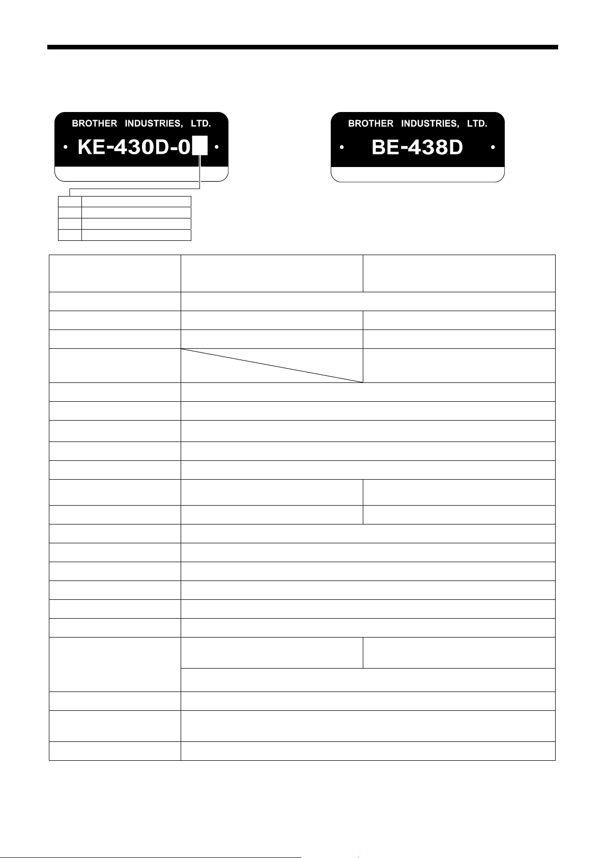
KE-430D
ELECTRONIC DIRECT DRIVE LOCKSTITCH
BAR TACKER
BE-438D
ELECTRONIC DIRECT DRIVE LOCKSTITCH
BUTTON SEWER

KE-430D, BE-438D
Thank you very much for buying a BROTHER sewing machine. Before using your new machine, please read the safety
instructions below and the explanations given in the instruction manual.
With industrial sewing machines, it is normal to carry out work while positioned directly in front of moving parts such as the
needle and thread take-up lever, and consequently there is always a danger of injury that can be caused by these parts.
Follow the instructions from training personnel and instructors regarding safe and correct operation before operating the
machine so that you will know how to use it correctly.
SAFETY INSTRUCTIONS
1. Safety indications and their meanings
This instruction manual and the indications and symbols that are used on the machine itself are provided in order to ensure
safe operation of this machine and to prevent accidents and injury to yourself or other people.
The meanings of these indications and symbols are given below.
Indications
DANGER
The instructions which follow this term indicate situations where failure to follow the
instructions will result in death or serious injury.
CAUTION
Symbols
・・・・・・
・・・・・・
・・・・・・
The instructions which follow this term indicate situations where failure to follow the
instructions could cause injury when using the machine or physical damage to equipment
and surroundings.
This symbol ( ) indicates something that you should be careful of. The picture inside the triangle
indicates the nature of the caution that must be taken.
(For example, the symbol at left means “beware of injury”.)
This symbol ( ) indicates something that you must not do.
This symbol ( ) indicates something that you must do. The picture inside the circle indicates the
nature of the thing that must be done.
(For example, the symbol at left means “you must make the ground connection”.)
KE-430D, BE-438D
i
2. Notes on safety
Wait at least 5 minutes after turning off the power switch and disconnecting the power cord from the wall outlet
before opening the face plate of the control box. Touching areas where high voltages are present can result in
severe injury.
DANGER
CAUTION
Environmental requirements
Use the sewing machine in an area which is free from
sources of strong electrical noise such as electrical
line noise or static electric noise.
Sources of strong electrical noise may cause
problems with correct operation.
Any fluctuations in the power supply voltage should
be within ±10% of the rated voltage for the machine.
Voltage fluctuations which are greater than this may
cause problems with correct operation.
The power supply capacity should be greater than the
requirements for the sewing machine’s power
consumption.
Insufficient power supply capacity may cause
problems with correct operation.
Installation
Machine installation should only be carried out by a
qualified technician.
Contact your Brother dealer or a qualified electrician
for any electrical work that may need to be done.
The sewing machine weighs approximately 56 kg.
The installation should be carried out by two or more
people.
Do not connect the power cord until installation is
complete, otherwise the machine may operate if the
foot switch is depressed by mistake, which could
result in injury.
Hold the machine head with both hands when tilting it
back or returning it to its original position.
Furthermore, after tilting back the machine head, do
not push the face plate side or the pulley side from
above, as this could cause the machine head to
topple over, which may result in personal injury or
damage to the machine.
Be sure to connect the ground. If the ground
connection is not secure, you run a high risk of
receiving a serious electric shock, and problems with
correct operation may also occur.
The ambient temperature should be within the range
of 5°C to 35°C during use.
Temperatures which are lower or higher than this
may cause problems with correct operation.
The relative humidity should be within the range of
45% to 85% during use, and no dew formation should
occur in any devices.
Excessively dry or humid environments and dew
formation may cause problems with correct operation.
In the event of an electrical storm, turn off the power
and disconnect the power cord from the wall outlet.
Lightning may cause problems with correct operation.
All cords should be secured at least 25 mm away
from any moving parts. Furthermore, do not
excessively bend the cords or secure them too firmly
with staples, otherwise there is the danger that fire or
electric shocks could occur.
Install the safety covers to the machine head and
motor.
If using a work table which has casters, the casters
should be secured in such a way so that they cannot
move.
Be sure to wear protective goggles and gloves when
handling the lubricating oil and grease, so that they
do not get into your eyes or onto your skin, otherwise
inflammation can result.
Furthermore, do not drink the oil or eat the grease
under any circumstances, as they can cause vomiting
and diarrhoea.
Keep the oil out of the reach of children.
ii
KE-430D, BE-438D
CAUTION
Sewing
This sewing machine should only be used by
operators who have received the necessary training
in safe use beforehand.
The sewing machine should not be used for any
applications other than sewing.
Be sure to wear protective goggles when using the
machine.
If goggles are not worn, there is the danger that if a
needle breaks, parts of the broken needle may enter
your eyes and injury may result.
Turn off the power switch at the following times,
otherwise the machine may operate if the foot switch
is depressed by mistake, which could result in injury.
• When threading the needle
• When replacing the needle and bobbin
• When not using the machine and when leaving the
machine unattended
Cleaning
Turn off the power switch before carrying out
cleaning, otherwise the machine may operate if the
foot switch is depressed by mistake, which could
result in injury.
If using a work table which has casters, the casters
should be secured in such a way so that they cannot
move.
Attach all safety devices before using the sewing
machine. If the machine is used without these
devices attached, injury may result.
Do not touch any of the moving parts or press any
objects against the machine while sewing, as this
may result in personal injury or damage to the
machine.
If an error occurs in machine operation, or if abnormal
noises or smells are noticed, immediately turn off the
power switch. Then contact your nearest Brother
dealer or a qualified technician.
If the machine develops a problem, contact your
nearest Brother dealer or a qualified technician.
Be sure to wear protective goggles and gloves when
handling the lubricating oil and grease, so that they
do not get into your eyes or onto your skin, otherwise
inflammation can result.
Furthermore, do not drink the oil or eat the grease
under any circumstances, as they can cause vomiting
and diarrhoea.
Keep the oil out of the reach of children.
Maintenance and inspection
Maintenance and inspection of the sewing machine
should only be carried out by a qualified technician.
Ask your Brother dealer or a qualified electrician to
carry out any maintenance and inspection of the
electrical system.
Turn off the power switch and disconnect the power
cord from the wall outlet at the following times,
otherwise the machine may operate if the foot switch
is depressed by mistake, which could result in injury.
• When carrying out inspection, adjustment and
maintenance
• When replacing consumable parts such as the
rotary hook
If the power switch needs to be left on when carrying
out some adjustment, be extremely careful to observe
all safety precautions.
KE-430D, BE-438D
Hold the machine head with both hands when tilting it
back or returning it to its original position.
Furthermore, after tilting back the machine head, do
not push the face plate side or the pulley side from
above, as this could cause the machine head to
topple over, which may result in personal injury or
damage to the machine.
Use only the proper replacement parts as specified
by Brother.
If any safety devices have been removed, be
absolutely sure to re-install them to their original
positions and check that they operate correctly before
using the machine.
Any problems in machine operation which result from
unauthorized modifications to the machine will not be
covered by the warranty.
iii
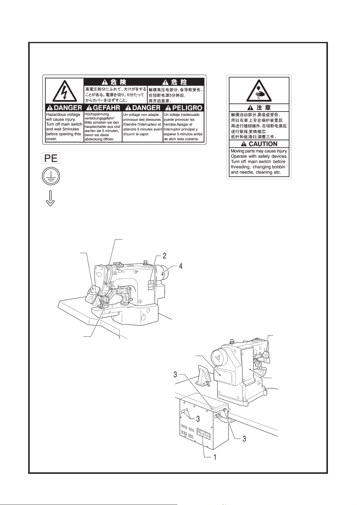
3. Warning labels
The following warning labels appear on the sewing machine.
Please follow the instructions on the labels at all times when using the machine. If the labels have been removed or are
difficult to read, please contact your nearest Brother dealer.
1 2
4
Be sure to connect the ground. If the ground
connection is not secure, you run a high risk of
receiving a serious electric shock, and problems
with correct operation may also occur.
Direction of operation
Thread take-up cover
Eye guard
3
Safety devices
Eye guard
Finger guard
Tension release solenoid cover
Thread take-up cover
Frame side cover
Back cover, etc.
Finger guard
Back cover
4399Q 4467Q
iv
KE-430D, BE-438D
Tension release
solenoid cover
Frame side cover

CONTENTS
1. NAMES OF MAJOR PARTS ................ 1
2. SPECIFICATIONS ................................ 2
2-1. Machine specifications ................................... 2
2-2. Program list (KE-430D) .................................. 3
2-3. Program list (BE-438D) .................................. 8
3. INSTALLATION....................................11
3-1. Table processing diagram.............................. 11
3-2. Installing the control box................................. 12
3-3. Installing the oil pan........................................ 12
3-4. Installing the machine head............................ 13
3-5. Installing the operation panel .........................14
3-6. Installing the treadle unit ................................ 14
3-7. Installing the cotton stand............................... 15
3-8. Installing the button tray (BE-438D) ............... 15
3-9. Installing the eye guard .................................. 15
3-10. Connecting the cords ................................... 16
3-11. Connecting the ground wire ......................... 18
3-12. Installing the back cover............................... 19
3-13. Lubrication .................................................... 20
3-14. Connecting the power cord .......................... 21
3-15. Starting up .................................................... 22
5. USING THE OPERATION PANEL
(BASIC OPERATIONS)........................31
5-1. Name and function of each
operation panel item .......................................31
5-2. Setting the program number ...........................33
5-3. Setting the X-scale and Y-scale......................33
5-4. Setting the sewing speed................................33
5-5. Checking the sewing pattern (KE-430D) ........34
5-6. Checking the sewing pattern (BE-438D) ........35
5-7. Adjusting the work clamp / button clamp
lift amount........................................................36
6. USING THE OPERATION PANEL
(ADVANCED OEPRATIONS)...............37
6-1. List of advanced functions ..............................37
6-2. Setting memory switches................................38
6-3. List of memory switches .................................39
6-4. Using the lower thread counter.......................40
6-5. Using the production counter..........................41
6-6. Using user programs ......................................42
6-7. Using cycle programs .....................................45
6-8. Direct selection ...............................................48
6-9. Loading additional sewing data ......................48
4. PREPARATION BEFORE SEWING .....23
4-1. Installing the needle........................................... 23
4-2. Threading the upper thread............................ 23
4-3. Winding the lower thread................................ 25
4-4. Installing the bobbin case............................... 26
4-5. Thread tension................................................ 26
4-5-1. Lower thread tension .......................... 26
4-5-2. Upper thread tension .......................... 27
4-6. Thread nipper device...................................... 28
4-7. Inserting the button (BE-438D)....................... 30
4-8. Adjusting the button clamp (BE-438D)........... 30
4-9. Installing the accessory spring (BE-438D) ..... 30
7. SEWING ...............................................49
8. MAINTENANCE....................................
8-1. Cleaning the rotary hook.................................50
8-2. Cleaning the control box air inlet ports ...........51
8-3. Draining the oil ................................................51
8-4. Cleaning the eye guard...................................51
8-5. Checking the needle .......................................51
8-6. Lubrication ......................................................51
8-7. Applying grease
(Work clamp: KE-430D) ..................................52
8-8. Applying grease
(When “GREASEUP” appears).......................52
50
9. TABLE OF ERROR CODES.................55
KE-430D, BE-438D

1. NAMES OF MAJOR PARTS
1. NAMES OF MAJOR PARTS
(1) Power switch
(2) Control box (10) Finger guard
(3) CF slot (11) Eye guard
(4) Operation panel (12) Thread take-up cover
(5) Foot switch (13) Back cover
(6) Work clamp (KE-430D) (14) Frame side cover
(7) Button clamp (BE-438D) (15) Tension release solenoid cover
(8) Pulley
(9) Cotton stand
TM
is a trademark of SanDisk Corporation.
CF
Safety devices
4400Q4401Q
1
KE-430D, BE-438D
2. SPECIFICATIONS
2-1. Machine specifications
1 Ordinary materials
2 Denim
7 Knitted materials
F Foundation garments
2. SPECIFICATIONS
Stitch formation Single needle lock stitch
Maximum sewing speed 3,200 rpm 2,700 rpm
Pattern size (X x Y) 40 x 30 mm max. 6.4 x 6.4 mm max.
Dimensions of buttons
that can be sewn
Feed mechanism
Stitch length 0.05 - 12.7 mm
Number of stitches
Maximum stitch number 210,000 stitches (including 200,000 stitches which can be added)
Work clamp lifter Pulse-motor driven mechanism
Work clamp height
Button clamp height
Rotary hook Shuttle hook (shuttle hook 2, optional) Shuttle hook
Wiper device Standard equipment
Thread trimmer device Standard equipment
Electronic direct drive lockstitch bar tacker
KE-430D
Electronic direct drive lockstitch button sewer
Outer diameter of button 8 - 30 mm (*1)
Y-θ intermittent feed mechanism (pulse-motor driven mechanism)
Variable (Refer to "Program List" for details on the number of stitches
for sewing patterns that are already preset.)
17 mm max. 13 mm max.
BE-438D
Thread nipper device Standard equipment
Data storage method Flash memory (Any sewing pattern can be added using CF card) (*2)
Number of user programs 50
Number of cycle programs 9
89 sewing patterns
Number of stored data
Motor AC servo motor 550 W
Weights
Power source
*1 Use the optional button clamp B (S03634-101) for diameters of 20 mm or greater.
*2 The recommended CF cards are commercially-available ones from SanDisk or HAGIWARA SYS-COM.
are set already
(Up to 200 patterns can be added. Total number of stitches of stored data
which can be added is within 200,000.)
Machine head: approx. 56 kg, Operation panel: approx. 0.6 kg
Control box: 14.2 – 16.2 kg (depending on destination)
Single-phase 100V / 220V, 3-phase 200V / 220V / 380V / 400V 400VA
KE-430D, BE-438D
53 sewing patterns
are set already
2

2. SPECIFICATIONS
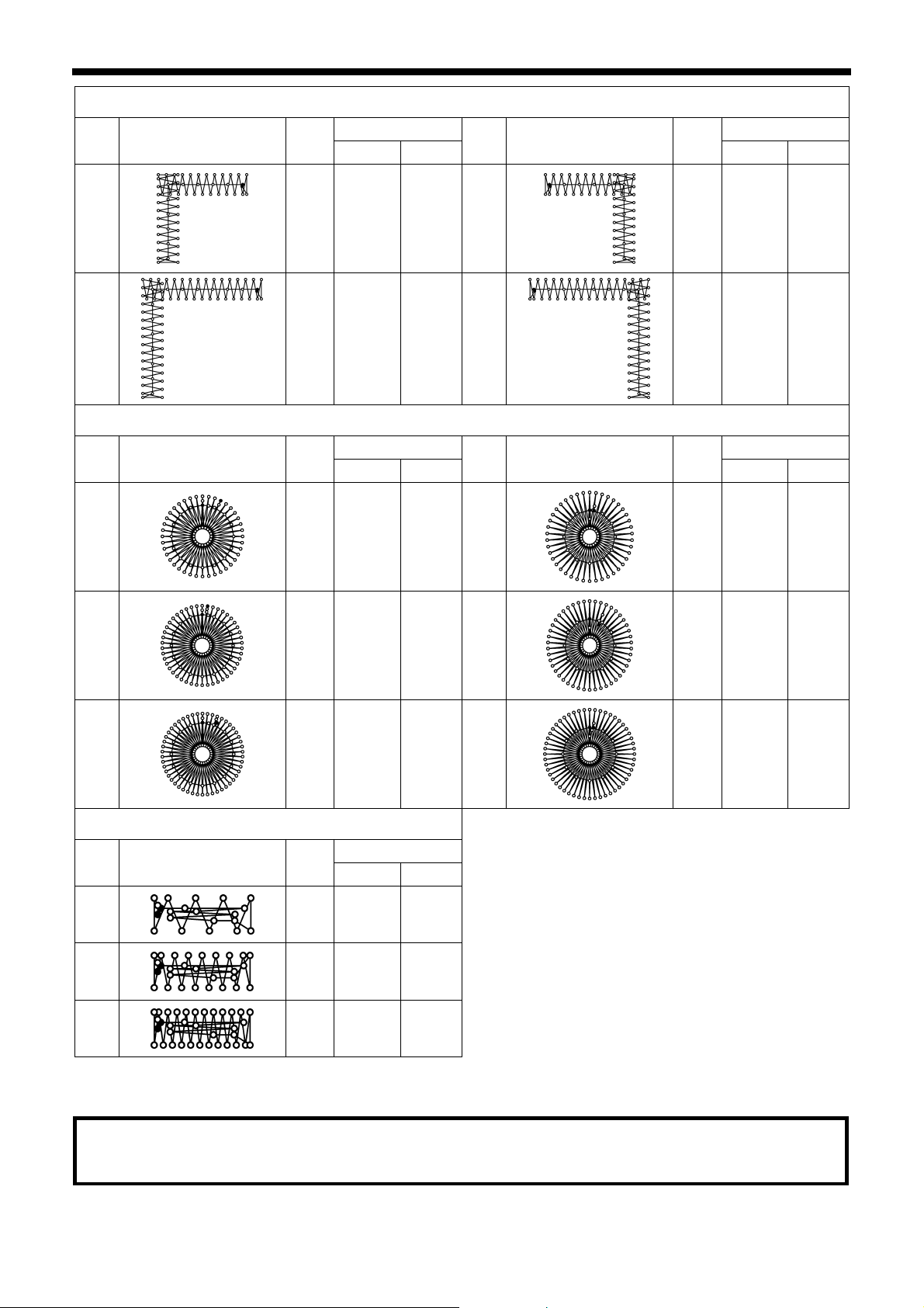
2-2. Program list (KE-430D)
The programs shown below have been preset into the sewing machine and can be selected according to specifications.
(Any program is available as long as the sewing pattern is within the work clamp and feed plate in size.)
Use the work clamp and feed plate that match the respective sewing pattern selected.
The sewing size is the length when the enlargement/reduction ratio is 100%.
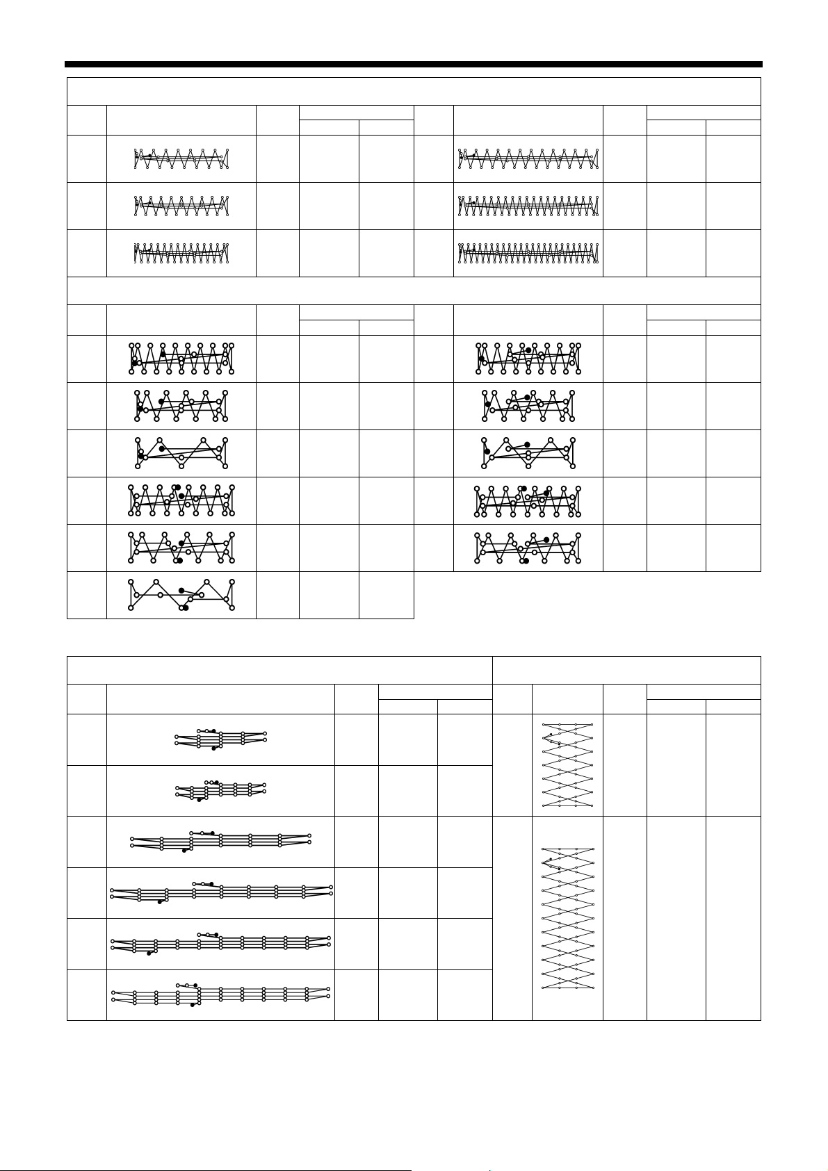
For ordinary materials (-01)
No. Sewing pattern
No. of
stitches
Tacking size (mm) Tacking size (mm)
Length
Width
No. Sewing pattern
1 42 16 2 65
4 31 16 2 66
5
8
13
15
20
21
29 10 2 67
21 7 2 68
35 10 2 69
42 10 2 70
28 7 2 71
35 7 2 72
No. of
stitches
Length
Width
43 16 2
32 16 2
30 10 2
22 7 2
36 10 2
43 10 2
29 7 2
36 7 2
64 30 16 2 89
For denim (-02)
No. Sewing pattern
2
3
6
14
16
No. of
stitches
Tacking size (mm) Tacking size (mm)
Length
Width
No. Sewing pattern
42 20 3 18
35 20 3 19
30 16 3 62
35 16 3 63
43 16 3 78
17 42 24 3 79
90 24 3
No. of
stitches
Length
56 24 3
64 24 3
42 20 3
35 20 3
43 20 3
36 20 3
Width
3
KE-430D, BE-438D
No. Sewing pattern
No. of
stitches
2. SPECIFICATIONS
For denim (-02)
Tacking size (mm) Tacking size (mm)
Length
Width
No. Sewing pattern
No. of
stitches
Length
Width
80
81
82
For Knitted materials (-07) and foundation garments (-0F)
No. Sewing pattern
7
9
22
31*
32*
31 16 3 83
36 16 3 84
44 16 3 85
No. of
stitches
Tacking size (mm) Tacking size (mm)
Length
Width
No. Sewing pattern
28 8 2 73
21 7 2 74
14 7 2 75
28 8 2 76*
22 8 2 77*
43 24 3
57 24 3
65 24 3
No. of
stitches
Length
Width
29 8 2
22 7 2
15 7 2
29 8 2
23 8 2
33*
15 8 2
* The sewing start and sewing end are in the middle of the pattern.
Straight bar tacking Vertical zigzag stitching
No. Sewing pattern
10
11
12
23
24
25
No. of
stitches
Tacking size (mm) Tacking size (mm)
Length
21 10 0.3
28 10 0.3
28 20 0.3
35 25 0.3
42 25 0.3
45 25 0.3
Width
No.
44
45
Sewing
pattern
No. of
stitches
Length
Width
46 9 15
70 9 25
KE-430D, BE-438D
4
2. SPECIFICATIONS
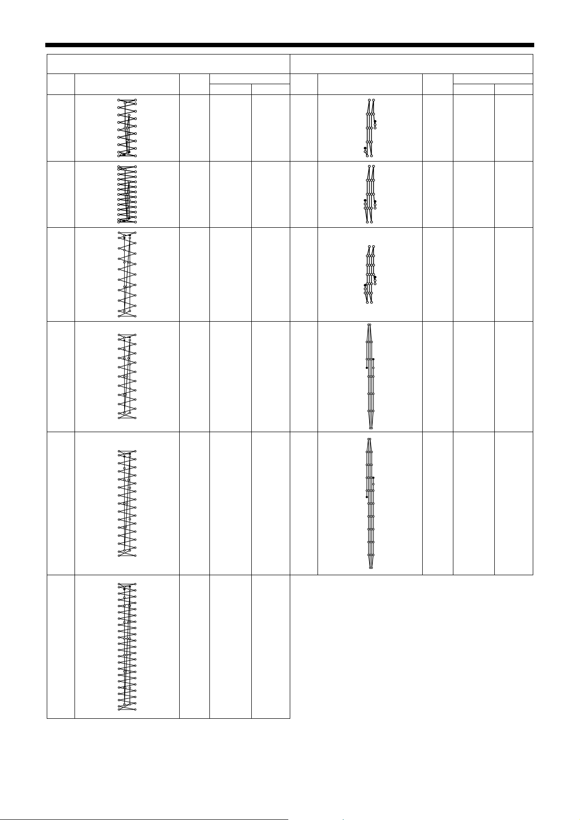
Vertical bar tacking Vertical straight bar tacking
No. Sewing pattern
No. of
stitches
Tacking size (mm) Tacking size (mm)
Length
Width
No. Sewing pattern
No. of
stitches
Length
Width
26
27
40
41
28 3 10 28
35 3 10 29
32 3 16 30
19 0.3 10
21 0.3 10
28 0.3 10
36 3 16 46
27 0.3 20
42
43
44 3 20 47
44 0.3 25
68 3 24
5
KE-430D, BE-438D
2. SPECIFICATIONS
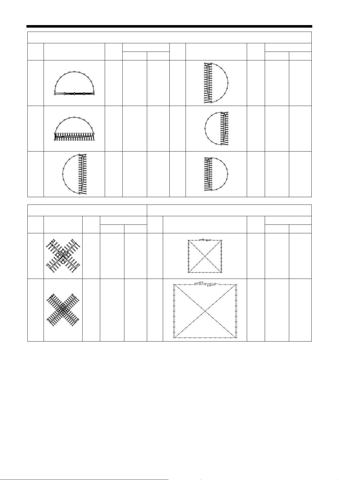
Crescent bar tacking
No. Sewing pattern
34
35
36
Crossed stitching
No. of
stitches
Tacking size (mm) Tacking size (mm)
Length
Width
No. Sewing pattern
35 12 7 37
58 12 7 38
57 7 12 39
Crossed tacking
No. of
stitches
Length
Width
57 7 12
53 7 10
53 7 10
No.
48
49
Sewing
pattern
No. of
stitches
Tacking size (mm) Tacking size (mm)
Length
Width
70 10 10 50
93 9.6 9.6 51
No. Sewing pattern
No. of
stitches
Length
Width
84 16 16
105 30 26
KE-430D, BE-438D
6
2. SPECIFICATIONS
L-pattern tacking
No. Sewing pattern
52
54
No. Sewing pattern
56
No. of
stitches
Tacking size (mm) Tacking size (mm)
Length
Width
No. Sewing pattern
60 11.3 11.2 53
78 15.3 15.2 55
Circular stitching
No. of
stitches
Tacking size (mm) Tacking size (mm)
Length
Width
No. Sewing pattern
106 9 9 59
No. of
stitches
Length
Width
60 11.3 11 .2
78 15.3 15.2
No. of
stitches
Length
Width
104 10 10
57
58
116 9 9 60
127 9 9 61
114 10 10
124 10 10
For eyelet buttonhole
No. Sewing pattern
86
No. of
stitches
Tacking size (mm)
Length
Width
21 6 2
87
28 6 2
88
35 6 2
If you want to sew a pattern other than standard patterns, you can create your original pattern using the PS-3000. Consult
with your local Brother sales Office for details.
Note when creating additional data (program nos. 200 - 999)
When sewing data with a small number of stitches (15 stitches or less) is sewn repeatedly (short cycle operation), the
upper shaft motor may overheat and the “E150” error code may be generated.
7
KE-430D, BE-438D
2. SPECIFICATIONS
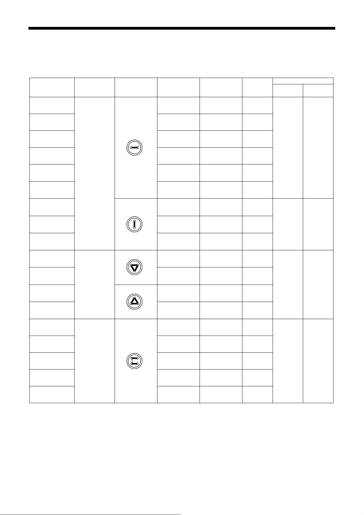
2-3. Program list (BE-438D)
The programs shown below have been preset into the sewing machine. Any program is available as long as the needle
drops down in the hole of the button.
When sewing programs that do not have crossover stitches, the thread is trimmed after sewing of one side is completed,
and then the other side is sewn.
Sewing size (mm)
X Y
No.
No. of
button holes
Sewing
pattern
No. of
threads
No. of
crossover
stitches
No. of
stitches
1 6
2 8
3 10
4 12
*1
5
*1
6
*2
7
*2
23
*2
8
*2
9
*2
24
*2
25
2
3
16 ― 22
20 ― 26
6 ― 12
10 ― 16
12 ― 18
5-5-5 ― 21
7-7-7 ― 27
5-5-5 ― 21
―
―
―
―
12
14
16
3.4 0
18
0 3.4
2.6 2.4
*2
26
10 6-6 1 19
11 8-8 1 23
12 8-8 3 25
13 10-10 1 27
27
*1 Check that the button hole diameter is 2 mm or greater before using the programs.
*2 Do not use the button lifter spring.
4
7-7-7 ― 27
3.4 3.4
12-12 1 31
KE-430D, BE-438D
8
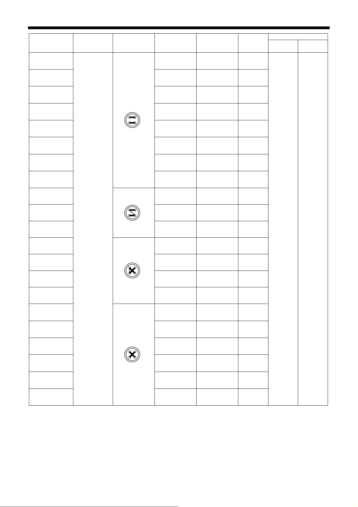
2. SPECIFICATIONS
No.
*3
14
No. of
button holes
Sewing
pattern
No. of
threads
No. of
crossover
stitches
No. of
stitches
Sewing size (mm)
6-6 0 24
X Y
36
28
37
15
38
29
39
*4
*3
*4
*3
*4
*3
*4
6-6 0 24
8-8 0 28
8-8 0 28
10-10 0 32
10-10 0 32
12-12 0 36
12-12 0 36
16 6-5 1 18
17 8-7 1 22
30
4
10-9 1 26
3.4 3.4
18 6-6 1 19
19 8-8 1 23
31 10-10 1 27
45
*3
20
*4
40
*3
32
*4
41
*3
33
*4
42
12-12 1 31
6-6 0 24
6-6 0 24
8-8 0 28
8-8 0 28
10-10 0 32
10-10 0 32
*3 When sewing of one side is completed, the button clamp rises and the thread is trimmed. To finish sewing, press the foot
switch until sewing of the other side starts, or press the foot switch again after sewing of the other side is completed.
*4 When sewing of one side is completed, the thread will be trimmed without the button clamp rising, and then the other
side will be sewn.
9
KE-430D, BE-438D
2. SPECIFICATIONS
Sewing size (mm)
X Y
No.
21
button holes
*2
No. of
Sewing
pattern
No. of
threads
No. of
crossover
stitches
No. of
stitches
6-6 1 19
*2
34
*2 *3
22
10-10 1 27
6-6 0 24
2.4 3.4
43
35
44
*2 *4
*2 *3
*2 *4
4
6-6 0 24
10-10 0 32
10-10 0 32
46 6-6 1 19
47 8-8 1 23
3.4 3.4
48 10-10 1 27
49
12-12 1 31
*2 Do not use the button lifter spring.
*3 When sewing of one side is completed, the button clamp rises and the thread is trimmed. To finish sewing, press the foot
switch until sewing of the other side starts, or press the foot switch again after sewing of the other side is completed.
*4 When sewing of one side is completed, the thread will be trimmed without the button clamp rising, and then the other
side will be sewn.
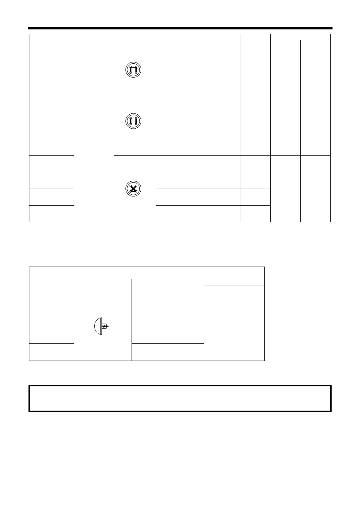
For shank button
No. Sewing pattern No. of threads
No. of
stitches
Sewing size (mm)
X Y
50 6 12
51 8 14
3.4 0
52 10 16
53
12 18
Note when creating additional data (program nos. 200 - 999)
When sewing data with a small number of stitches (15 stitches or less) is sewn repeatedly (short cycle operation), the
upper shaft motor may overheat and the “E150” error code may be generated.
KE-430D, BE-438D
10
3. INSTALLATION
3. INSTALLATION
CAUTION
Machine installation should only be carried out by a
qualified technician.
Contact your Brother dealer or a qualified electrician
for any electrical work that may need to be done.
The sewing machine head weighs approximately 56
kg. The installation should be carried out by two or
more people.
Do not connect the power cord until installation is
complete, otherwise the machine may operate if the
foot switch is depressed by mistake, which could
result in injury.
Hold the machine head with both hands when tilting it
back or returning it to its original position.
Furthermore, after tilting back the machine head, do
not push the face plate side or the pulley side from
above, as this could cause the machine head to
topple over, which may result in personal injury or
damage to the machine
.
All cords should be secured at least 25 mm away
from any moving parts. Furthermore, do not
excessively bend the cable or secure it too firmly
staples, otherwise there is the danger that fire or
electric shocks could occur.
Be sure to connect the ground. If the ground
connection is not secure, you run the risk of receiving
a serious electric shock, and problems with correct
operation may also occur.
Install the safety covers to the machine head and
motor.
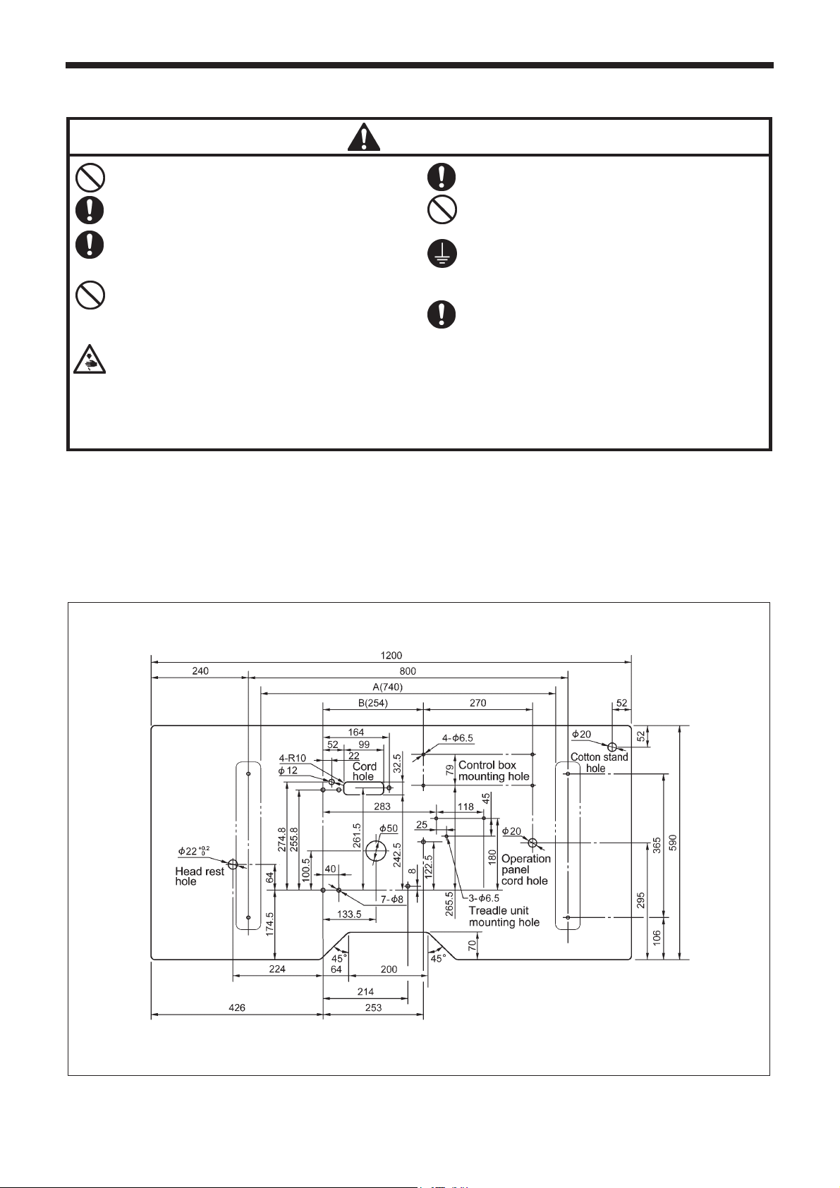
3-1. Table processing diagram
• The thickness of the table should be at least 40 mm, and it should be strong enough to bear the weight and vibration of the
sewing machine.
• If the distance A between the insides of the legs is less than 740 mm, move the control box installation position to the left (B
= 254 mm).
• Check that the control box is at least 10 mm away from the leg. If the control box and the leg are too close together, it may
result in incorrect sewing machine operation.
11 KE-430D, BE-438D
3625M
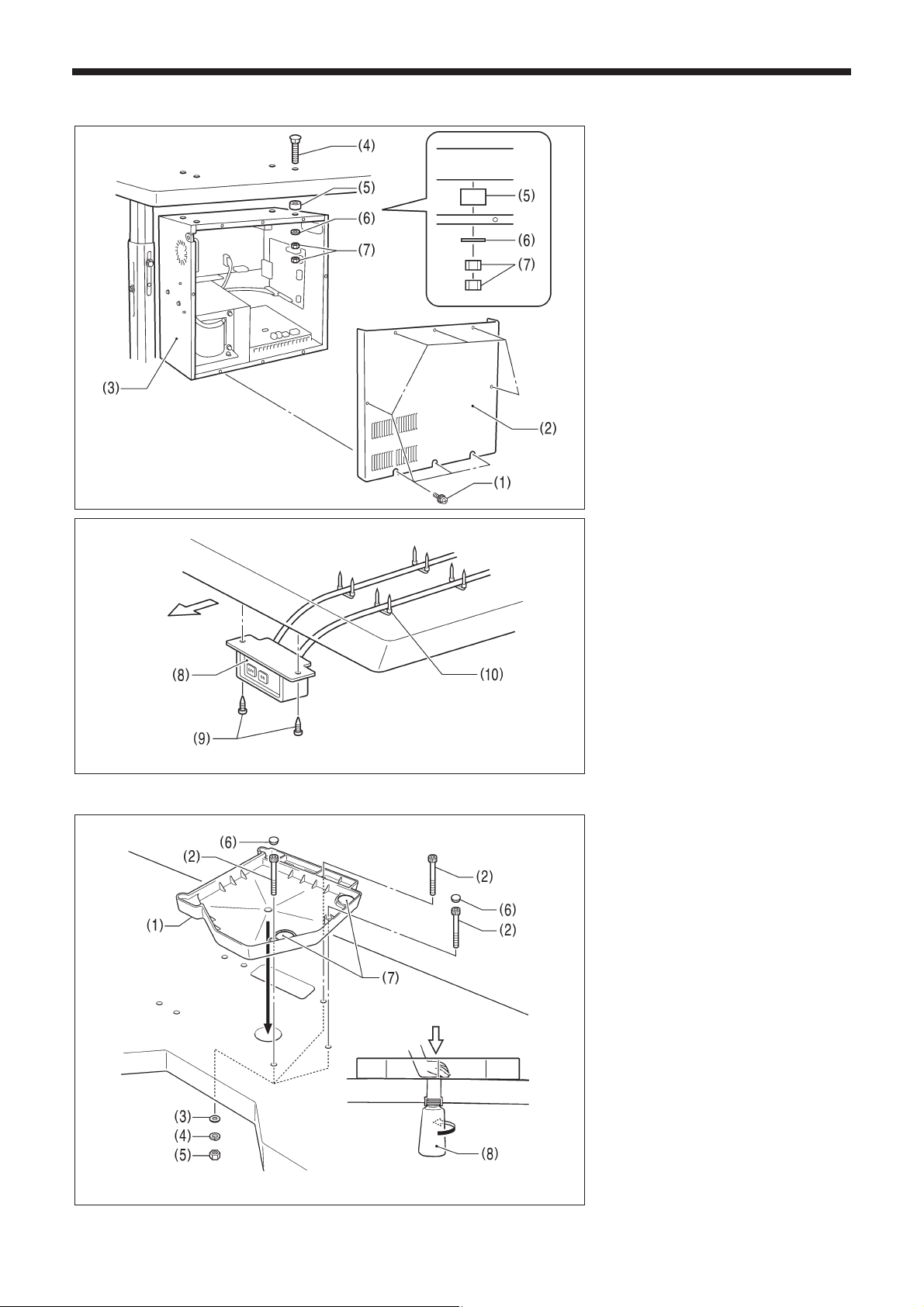
3-2. Installing the control box
Operator
4403Q
4404Q
3. INSTALLATION
Remove the eight screws (1), and then
remove the control box cover (2).
(3) Control box
(4) Bolts [4 pcs]
(5) Spacers [4 pcs]
(6) Plain washers [4 pcs]
(7) Nuts [8 pcs]
* The recommended tightening
torque for the nuts (7) is
4.0±0.1N・m.
(8) Power switch
(9) Wood screws [2 pcs]
(10) Staples [4 pcs]
3-3. Installing the oil pan
(1) Oil pan
(2) Bolts [3 pcs]
(3) Plain washers [3 pcs]
(4) Spring washers [3 pcs]
(5) Nuts [3 pcs]
(6) Rubber caps [2 pcs]
(7) Rubber cushion [2 pcs]
(8) Oiler
4405Q
12KE-430D, BE-438D
3. INSTALLATION
A
A
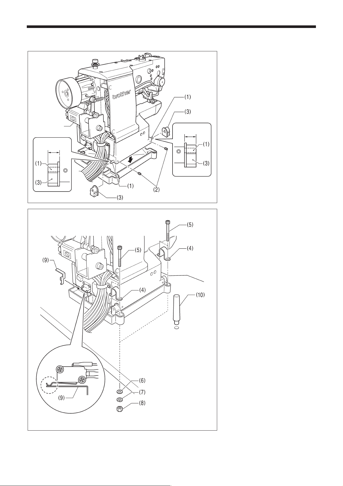
3-4. Installing the machine head
Pulse motor
pprox. 20mm
Figure1
pprox. 20mm
4406Q
(1) Pins [2 pcs]
(2) Set screws [2 pcs]
(3) Rubber cushion assembly [2 pcs]
Place the machine head gently on top of
the oil pan and the rubber cushions.
Note:
• Be careful not to clamp any cords
between the machine head and the
oil pan.
• When holding the machine head, do
not hold it by the pulse motor,
otherwise it may damage the pulse
motor.
(4) Hinge holders [2 pcs]
(5) Bolts [4 pcs]
(6) Plain washers [4 pcs]
(7) Spring washers [4 pcs]
(8) Nuts [4 pcs]
(9) Head spring
(10) Head rest
Note:
• Check that the machine head switch
is turned on as shown in Figure 1.
• Tap the head rest (10) securely into
the table hole.
4407Q
13
KE-430D, BE-438D
 Loading...