

Page 1
Installation and Operation Manual
X-VA 2500 Series-eng
Part Number: 541B165AAG
May, 2011
Brooks® 2500 Series Flowmeters
Brooks® Models 2510, 2520, 2530
Acrylic block flowmeters are available in various sizes
and ranges, with direct reading scales in both SAE and
SI units for air and water. For other gases or liquids,
special scales can be provided. If you use this meter
with fluids other than air or water, please consult
chemical compatibility data for possible effects on the
meter. These meters are manufactured of durable
acrylic and if properly installed and maintained, will
provide long-term trouble-free operation.
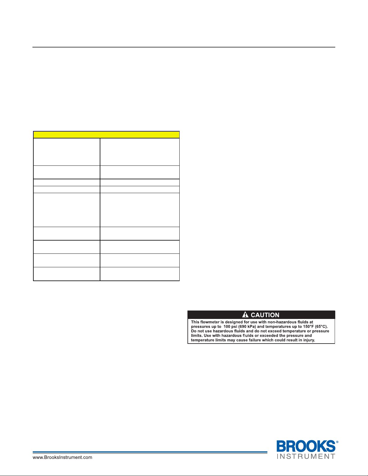
SPECIFICATIONS
2510 Series
ACCURACY:
FLOATS:
METER BODY:
FITTINGS:
ELASTOMERS:
VALVES:
MOUNTING
INSERTS:
MAXIMUM
TEMPERATURE:
MAXIMUM
PRESSURE:
± 5% Full Scale
2520 2530 Series
± 3% Full Scale
Black Glass, Stainless Steel,
Aluminum or Black Delri n
Clear Acrylic
Brass or Stainless Steel
Buna-N with Brass
Viton fluoroelastomers
Brass or Stainless Steel
Cartridge Type (Optional)
10-32 UNF
150°F (65 °C)
100 PSIG (690 kPa)
®
Fittings
O-rings with Stainless
Steel fittings
UNPACKING
Precautions have been taken to prevent any damage
from occurring during shipment. However, if the meter
is received damaged, report it to the carrier
immediately. Before installing, verify that you have the
model and flow range required.
INSTALLATION
These meters are supplied with 5/8" or 7/8" hex's on the
inlet and outlet fittings. When installing 1/8-27 MNPT or
¼-18 MNPT fittings into the meter, place the
appropriate size wrench on the hex to prevent the inlet/
outlet fitting from rotating. Torque only to 60 in-lbs.
Failure to do so will cause the fitting to rotate, and may
damage the meter body, causing leaks and/or meter
failure. Use pipe thread sealant or Teflon® tape to ease
installation and provide a better seal. This meter is
supplied with #10-32 threaded inserts for mounting.
When installing, use slotted screws and torque to a
maximum of 35 in-lbs. Mounting dimensions are shown
in Figure 1.
CLEANING AND DISASSEMBLY
Occasional cleaning may be required if dirt appears in
the flow tube or if float movement becomes restricted.
To clean, remove the top plug and remove the float.
Wash the tapered hole and top plug with a mild liquid
detergent and soft brush. Rinse all parts with clean
water and dry thoroughly with clean air or nitrogen. Do
not use solvents to clean this meter as they will attack
the acrylic and destroy the meter.
REASSEMBLY
Check to make sure that all parts are clean and dry. To
lubricate the O-rings, apply a small amount of
halocarbon grease prior to reassembly. If applicable,
reinstall the rod guide assembly into the flowmeter
body. Make sure the rod guide is seated firmly in the
body of the meter. Reinstall the top plug, making sure
that the rod guide is properly aligned. Tighten top plug
until it's flush with top of acrylic body. Exceeding this
may damage the meter body.
ACHIEVING ACCURATE FLOWRATES
To obtain an accurate flowrate, the float must be read at
the position indicated on the meter. If the meter uses a
ball float, the flowrate is determined by reading the
center of the ball. Additionally, the flowmeter should be
installed in a manner, which minimizes both external
vibrations and internal flow variations. Special care
should be taken so that the connections to the meter's
inlet and outlet fittings do not overly restrict the liquid or
gas flow being metered. This could result in a reduced
flow volume, preventing the meter from reaching its
maximum flowrate. Furthermore, internal pressures
could be affected, which can cause inaccurate flow
readings. On start-up, slowly purge any fluid trapped in
the meter.
Page 2
Brooks® 2500 Series Flowmeters
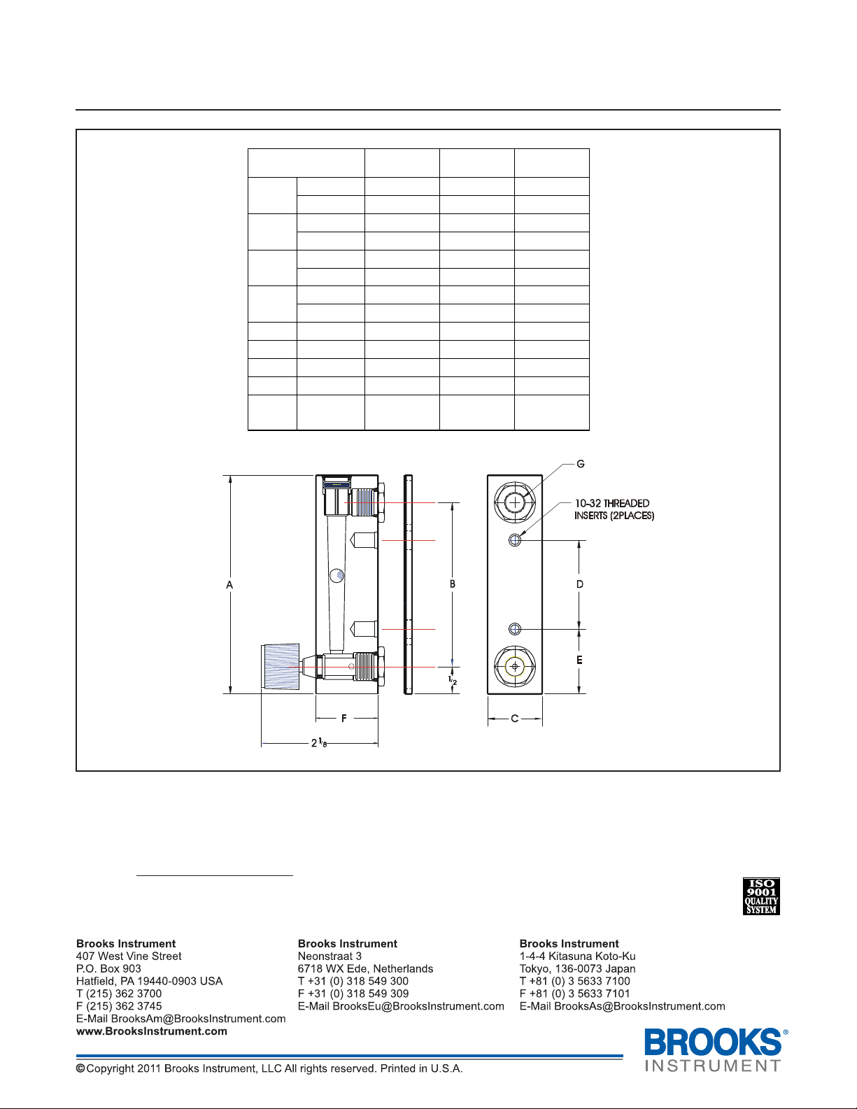
DIMENSIONS 2510 2520 2530
Installation and Operation Manual
X-VA-2500 Series-eng
Part Number: 541B165AAG
May, 2011
A
B
C
D
IN.
mm 102 165 168
IN. 3 5 ½ 5 1/2
mm 76.2 140 140
IN. 1 1 3/8 1 1/8
mm 25.4 34.9 28.6
IN.
mm
E IN.
mm
F IN.
mm
G IN.
4 6 ½ 6 5/8
1 5/8 3 ½ 3 ½
41.3 88.9 88.9
1 3/16 1 1/2 1 1/2
30.2 38.1 38.1
1 1/8 1 1/8 1 3/8
28.6 28.6 34.9
1/8-27
MNPT
1/8-27
MNPT
¼-18
MNPT
Figure 1 Dimensions for Brooks 2500 Series Flowmeters
Due to Brooks Instrument’s continuous improvement of our products, all specifications are subject to change without
notice.
If you have any questions regarding installation, maintenance, replacement or use of this flowmeter, please visit our
website at www.BrooksInstrument.com for Customer Service contact information.
 Loading...